

Page 1

Instructions
K4000
TransportCart
071-0833-01
www.tektronix.com
*P071083301*
071083301
Page 2

Copyright © Tektronix, Inc. All rights reserved.
Tektronix products are covered by U.S. and foreign patents, issued and pending. Information in this public ation supercedes
that in all previously published material. Specifications and price c hange privileges reserved.
Tektronix, Inc., P.O. Box 500, Beaverton, OR 97077
TEKTRONIX and TEK are registered trademarks of Tektronix, Inc.
Page 3

WARRANTY
Tektronix warrants that the products that it manufactures and sells will be free from defects in materials and workmanship
for a period of one (1) year from the date of shipment. If a product proves defective during this warranty period, Tektronix,
at its option, either will repair the defective product without charge for parts and labor, or will provide a replacement in
exchange for the defective product.
In order to obtain service under this warranty, Customer must notify Tektronix of the defect before the expiration of the
warranty period and make suitable arrangements for the performance of service. Customer shall be responsible for
packaging and shipping the defective product to the service center designated by Tektronix, with shipping charges prepaid.
Tektronix shall pay for the return of the product to Customer if the shipment is to a location within the country in which the
Tektronix service center is located. Customer shall be responsible for paying all shipping charges, duties, taxes, and any
other charges for products returned to any other locations.
This warranty shall not apply to any defect, failure or damage caused by improper use or improper or inadequate
maintenance and care. Tektronix shall not be obligated to furnish service under this warranty a) to repair damage resulting
from attempts by personnel other than Tektronix representatives to install, repair or service the product; b) to repair
damage resulting from improper use or connection to incom patible equipm ent; c) to repair any damage or malfunction
caused by the use of non--Tektronix supplies; or d) to service a product that has been modified or integrat ed with other
products when the effect of such modification or integration increases the time or difficulty of servicing the product.
THIS WARRANTY IS GIVEN BY TEKTRONIX IN LIEU OF ANY OTHER WARRANTIES, EXPRESS OR IMPLIED.
TEKTRONIX AND ITS VENDORS DISCLAIM ANY IMPLIED WARRANTIES OF MERCHANTABILITY OR
FITNESS FOR A PARTICULAR PURPOSE. TEKTRONIX
DEFECTIVE PRODUCTS IS THE SOLE AND EXCLUSIVE REMEDY PROVIDED TO THE CUSTOMER FOR
BREACH OF THIS W ARRANTY. TEKTRONIX AND ITS VENDORS WILL NOT BE LIABLE FOR ANY INDIRECT,
SPECIAL, INCIDENTAL, OR CONSEQUENTIAL DAMAGES IRRESPECTIVE OF WHETHER TEKTRONIX OR THE
VENDOR HAS ADVANCE NOTICE OF THE POSSIBILITY OF SUCH DAMAGES.
ٛ RESPONSIBILITY TO REPAIR OR REPLACE
Page 4

Page 5

Table of Contents
General Safety Summary iii...................................
Contacting Tektronix iv.............................................
Introduction 1..............................................
Tools 1..........................................................
Parts Identification 1...............................................
Base Assembly 5............................................
Bottom Shelf 9..............................................
Keyboard Shelf 11...........................................
Top Shelf 14.................................................
Drawer 16..................................................
Skyhook 18.................................................
Nylon Straps 20..............................................
Leg Caps 21.................................................
Stop Bar 22.................................................
Monitor Clamps 23...........................................
Instrument Mounts 24........................................
Customization 26............................................
Replaceable Parts 27..........................................
Specifications 28.............................................
29...................................
K4000 Transport Cart Instructions
i
Page 6

Table of Contents
List of Figures
Figure 1: Identification of Small Parts 2........................
Figure 2: The K4000 Transport Cart 4..........................
Figure 3: Preparing the Strut for Base Assembly 6................
Figure 4: Aligning the Leg Assemblies and the Strut 8.............
Figure 5: Installing the Casters 9..............................
Figure 6: Preparing the Bottom Shelf 10.........................
Figure 7: Aligning the Bottom Shelf 11..........................
Figure 8: Preparing the Keyboard Shelf 12.......................
Figure 9: Aligning the Keyboard Shelf 14........................
Figure 10: Preparing the Top Shelf 15...........................
Figure 11: Aligning the Top Shelf 16.............................
Figure 12: Installing the Drawer 17.............................
Figure 13: Installing the Press Stud Retainers 18..................
Figure 14: Installing the Skyhook 20............................
Figure 15: Installing the Nylon Straps with Buckles 21.............
Figure 16: Installing the Leg Caps 22............................
Figure 17: Installing the Stop Bar 23............................
Figure 18: Installing the Monitor Clamps 24......................
Figure 19: Installing the Instrument M ou nts 26..................
ii
K4000 Transport Cart Instructions
Page 7

General Safety Summary
Observe these safety precautions when using the K4000 Transport Cart.
Keep the K4000 Level
Keep the K4000 level at all times, especially when it is loaded with instruments.
The cart is designed to be very stable, but it can fall over if tilted to extremes.
Observe this precaution especially in these cases:
H When rolling the cart across uneven floors.
H When rolling the cart through doorways with uneven thresholds.
H When lifting the cart wheels over cables.
H When rolling the cart up or down ramps.
Do Not Overload Shelves
Do not put more weight on any cart shelf than is listed in the specifications.
Load the top of the cart evenly.
Observe Electrical Safety
All parts of the cart must be treated as electrical conductors, even if they appear
to be nonconducting. Do not rely on the casters to provide insulation between the
cart and the surface it stands on. Conversely, do not rely on the casters to provide
a conductive ground path for the cart.
T est the Stability of Custom Configurations
Changes in shelf location and loading can affect the balance of the cart. If you
arrange the shelves differently from the configuration described in this manual,
test the cart carefully for stability before using it.
K4000 Transport Cart Instructions
iii
Page 8

Preface
Contacting Tektronix
Phone 1-800-833-9200*
Address Tektronix, Inc.
Department or name (if known)
14200 SW Karl Braun Drive
P.O. Box 500
Beaverton, OR 97077
USA
Web site www.tektronix.com
Sales support 1-800-833-9200, select option 1*
Service support 1-800-833-9200, select option 2*
Technical support Email: techsupport@tektronix.com
1-800-833-9200, select option 3*
6:00 a.m. -- 5:00 p.m. Pacific time
* This phone number is toll free in North America. After office hours, please leave a
voice mail message.
Outside North America, contact a Tektronix sales office or distributor; see the
Tektronix web site for a list of offices.
iv
K4000 Transport Cart Instructions
Page 9

Introduction
Tools
The Tektronix K4000 Transport Cart requires some assembly. This manual tells
how to assemble and use the cart.
You can assemble the K4000 Transport Cart by yourself, but it is easier if you
have another person to help you.
You will need a large flat area to assemble the cart. The area should be level and
large enough to move the various parts into place. A carpeted floor space is ideal.
Assembly will require approximately 2 hours.
You will need a 3/4 inch (19 mm) open--end wrench, or an adjustable wrench that
can be adjusted to that size.
Other tools are included with the K4000 Transport Cart. These include a 3/16
inch Allen wrench and a circular bubble level.
Parts Identification
The large pieces of the K4000 Transport Cart are packed separately in the
shipping carton. A bag of small parts is packed in a box with thes casters and
other small parts. The included tools are also packed in this bag. Figure 1 on
page 2 shows the small parts you will be using.
Table 1 on page 3 lists all the parts needed to assemble the cart, including the
large pieces and assemblies. Take an inventory now to familiarize yourself with
the parts for the assembly process.
K4000 Transport Cart Instructions
1
Page 10

Introduction
Figure 1: Identification of Small Parts
2
Press On Probe Holder
K4000 Transport Cart Instructions
Page 11

Table 1: Parts List
Quantity Desscription
Large Parts
2 Locking Casters
2 Non--Locking Casters
1 Top Shelf
1 Keyboard Shelf
1 Bottom Shelf
1 Drawer
1 Strut
2 Leg assemblies
2 Upright Caps
4 Nylon Straps with buckles
1 Skyhook
Introduction
1 Skyhook Mount
1 Skyhook Adjustment Knob
1 Skyhook Sleeve
1 Stop Bar
4 Monitor Clamps
2 Instrument Mounts
4 End C aps
Small Parts in Bag
4 1/2 inch Split Lockwashers
22 1/4--20 x 1/2 inch Cap Head Screws
22 1/4 inch Tooth Lockwashers
22 Weld Nuts
2 Press--Stud Retainers
6 #8--32 Wing Nuts
4 1/4--20 x 1--1/4 inch Cap Head Screws
4 1 inch Fender Washers
1 Press On Probe Holder
K4000 Transport Cart Instructions
Small Tools in Bag
1 3/16 inch Allen Wrench
1 Circular Bubble Level
3
Page 12

Introduction
Figure 2: The K4000 Transport Cart
4
K4000 Transport Cart Instructions
Page 13

Base Assembly
Begin assembling the cart by joining the leg assemblies using the strut, and then
putting on the casters. You will use these parts:
H 2 Locking Casters
H 2Non--LockingCasters
H 2 Uprights
H 2Legs
H 4 End Caps
H 1Strut
H 4 1/2 inch Split Lockwashers
H 4 1/4 20 Cap Head Screws, 1/2 inch length
H 4 1/4 inch Tooth Lockwashers
H 4 1/4 20 Cap Head Screws, 1--1/4 inch length
H 4 1 inch Fender Washers
H 4WeldNuts
H 4 Bumpons
You will use a 3/4 inch (19 mm) wrench or adjustable wrench, and the 3/16 inch
Allen wrench included with your cart.
1. Prepare the strut as shown in Figure 3. P osition the weld nut with the raised
threaded flange toward the strut. Leave each screw assembly loose; do not
screw the weld nut onto the cap head screw more than one full turn.
K4000 Transport Cart Instructions
5
Page 14

Base Assembly
Front
Weld Nut
1/4 inch Tooth Lockwasher
1/4-20 Cap Head Screw
Figure 3: Preparing the Strut for Base Assembly
2. Attach legs to the upright using the 1/4--20 x 1--1/4 inch cap head screws and
the 1 inch fender washers provided. Place the endcaps in the ends of th elegs
and press in using firm pressure.
NOTE. Position each leg so that the two large holes face down when attaching
legs to uprights.
3. Place four bumpons in--line as indicated by Figure 4. Two of the bumpons
are placed on the inside top surface of each leg and in--line with the back
groove. The remaining two bumpons are placed on top of the strut in--line
with the back groove.
6
K4000 Transport Cart Instructions
Page 15

Base Assembly
Pencil Marks: first line should be 10 inches
from the bottom of the extrusion. For the first
leg assembly, turn extrusion so pencil marks
are on the inside. For second leg assembly,
pencil marks are also on the inside.
Bumpons are on the
inside of the extrusions.
Clear Plastic Buttons (1 on each leg assembly)
Note: Leg tube can be crushed if screw is over
tightened; maximum torque is 3-6 foot/pounds.
Figure 4: Aligning the Leg Assemblies and the Strut
4. Position the strut horizontally between the leg assemblies, as shown in
Figure 4, with the open side of the strut to the back. Line up the weld nuts
with the back grooves of each upright. Slide the strut down to the base of the
cart, adjusting the distance between the leg assemblies as needed. When
complete, make sure the strut is resting tight against the bumpons placed on
the legs.
5. Use the 3/16 inch Allen wrench to tighten the cap head screws. Tighten them
first snugly, then go back and tighten them firmly.
K4000 Transport Cart Instructions
7
Page 16

Base Assembly
NOTE. If you have a torque wrench available, tighten these and all shelf screws
to 60 in.... lb (6.8 N.... m) torque.
6. Tip the cart onto its back as shown in Figure 5, resting it on the work surface
by the tops and backs of the leg assemblies.
7. Identify which casters are locking and which are non--locking. The locking
casters, which go on the front of the cart, have an extra tab that you step on
to lock the wheels.
Non-
Locking
Casters
Locking
Casters
1/2 inch Split
Lockwashers
Front
Figure 5: Installing the Casters
8. On the locking casters, place a 1/2 inch split lockwasher on each threaded
shaft, then install the casters into the two front holes in the bottoms of the
leg assemblies. Tighten the casters only until they are snug using the 3/4
inch (19 mm) wrench.
9. On the non--locking casters, place a 1/2 inch split lockwasher on each
threaded shaft, then install the casters into the two back holes in the bottoms
of the leg assemblies. Tighten the casters only until they are snug.
10. Return the cart to the upright position.
8
K4000 Transport Cart Instructions
Page 17

Bottom Shelf
Installing the bottom shelf. You will use these parts:
H 1 Bottom Shelf
H 4 1/4 20 Cap Head Screws, 1/2 inch length
H 4 1/4 inch Tooth Lockwashers
H 4WeldNuts
You will use the 3/16 inch Allen wrench and the circular bubble level included
with your cart.
1. Prepare the bottom shelf as shown in Figure 6 by installing a cap head screw,
a tooth lockwasher, and a weld nut in each of the four side holes of the shelf.
Leave each screw assembly loose; do not screw the weld nut onto the cap
head screw more than one full turn.
Figure 6: Preparing the Bottom Shelf
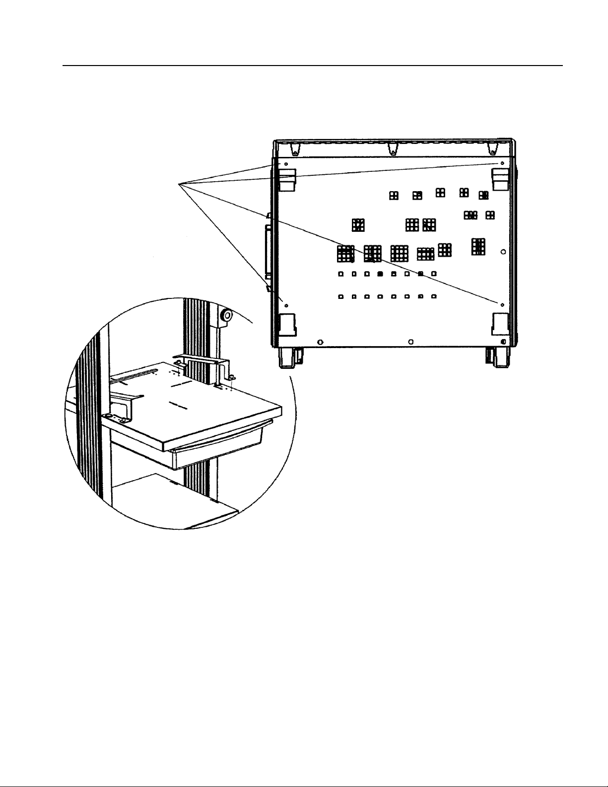
2. Position the bottom shelf horizontally between the leg assemblies, as shown
K4000 Transport Cart Instructions
in Figure 7. Ensure that the cable tie hole pattern is facing the rear of the
cart.
9
Page 18

Bottom Shelf
Figure 7: Aligning the Bott om Shelf
3. Slide the bottom shelf down to into position. A light pencil line has been
marked on the insides of the leg assemblies at this position. Slide the bottom
shelf slowly between the leg assemblies to avoid scratching the paint. Use
the circular bubble level to make sure the shelf is level.
If you have another person helping you, that person can hold the shelf at the
proper height as you tighten the screws. If you are assembling the cart by
yourself, tighten each screw in turn just enough to hold, and then adjust the
heights one by one until the shelf is positioned properly.
4. Use the 3/16 inch Allen wrench to tighten the cap head screws. Tighten them
first snugly, then go back and tighten them firmly.
10
K4000 Transport Cart Instructions
Page 19

Keyboard Shelf
Installing the keyboard shelf. You will use these parts:
H 1 Keyboard Shelf
H 8 1/4 20 Cap Head Screws, 1/2 inch length
H 8 1/4 inch Tooth Lockwashers
H 8WeldNuts
You will use the 3/16 inch Allen wrench and the circular bubble level included
with your cart.
1. Prepare the keyboard shelf as shown in Figure 8 by installing a cap head
screw, a tooth lockwasher, and a weld nut in each of the eight side holes of
the shelf. Leave each screw assembly loose; do not screw the weld nut onto
the cap head screw more than one full turn.
Figure 8: Preparing the Keyboard Shelf
K4000 Transport Cart Instructions
11
Page 20

Keyboard Shelf
2. Position the keyboard shelf horizontally between the leg assemblies, as
shown in Figure 9. Position the shelf so that the long end of the shelf is
positioned to the front of the cart.
3. Slide the keyboard shelf down to into position. (A light pencil line has been
marked on the insides of the leg assemblies at the keyboard shelf position.)
Slide the keyboard shelf slowly between the leg assemblies to avoid
scratching the paint. Use the circular bubble level to make sure the shelf is
level.
If you have another person helping you, that person can hold the shelf at the
proper height as you tighten the screws. If you are assembling the cart by
yourself, tighten each screw in turn just enough to hold, and then adjust the
heights one by one until the shelf is positioned properly.
4. Use the 3/16 inch Allen wrench to tighten the cap head screws. Tighten them
first snugly, then go back and tighten them firmly.
12
K4000 Transport Cart Instructions
Page 21

Keyboard Shelf
K4000 Transport Cart Instructions
Figure 9: Aligning the Keyboard Shelf
13
Page 22

Top Shelf
Installing the top shelf. You will use these parts:
H 1 Top Shelf
H 4 1/4 20 Cap Head Screws, 1/2 inch length
H 4 1/4 inch Tooth Lockwashers
H 4WeldNuts
You will use the 3/16 inch Allen wrench and the circular bubble level included
with your cart.
1. Prepare the top shelf as shown in Figure 10 by installing a cap head screw, a
tooth lockwasher, and a weld nut in each of the four side holes of the shelf.
Leave each screw assembly loose; do not screw the weld nut onto the cap
head screw more than one full turn.
Figure 10: Preparing the Top Shelf
14
2. Position the top shelf horizontally between the leg assemblies, as shown in
Figure 11. Position the shelf so that the Tektronix logo is facing the front of
the cart.
K4000 Transport Cart Instructions
Page 23

Top Shelf
Figure 11: Aligning the Top Shelf
3. Slide the top shelf down to into position. Align the top of the shelf so that it
is flush with the tops of the uprights.
If you have another person helping you, that person can hold the shelf at the
proper height as you tighten the screws. If you are assembling the cart by
yourself, tighten each screw in turn just enough to hold, and then adjust the
heights one by one until the shelf is positioned properly.
4. Use the 3/16 inch Allen wrench to tighten the cap head screws. Tighten them
first snugly, then go back and tighten them firmly.
K4000 Transport Cart Instructions
15
Page 24

Drawer
1. Slide the Drawer in underneath the keyboard shelf as shown in Figure 12.
Position the drawer so that the curved edge is to the front of the cart. Slide
the drawer into the shelf until it stops.
Figure 12: Installing the Drawer
16
K4000 Transport Cart Instructions
Page 25

Drawer
2. With the drawer pushed all the way back to the stops, use your thumb to
press into place the two press--stud retainers at the bottom of the drawer rails,
as shown in Figure 13.
Figure 13: Installing the Press Stud Retainers
K4000 Transport Cart Instructions
17
Page 26

Skyhook
Install the Skyhook. You will use these parts:
H 1 Sleeve
H 1 Adjustment Knob
H 1 Mount
H 2WeldNuts
H 2 1/4 20 Cap Head Screws, 1/2 inch length
H 2 1/4 inch Tooth Lockwashers
H 2 Bushings
H 2 Grommets
You will use the 3/16 inch Allen wrench included w ith your cart.
1. Press the two grommets into the large holes on either side of the keyboard
shelf.
2. Install the weld nuts, lockwashers and cap head scress on the mount as
illustrated. Leave each screw assembly loose; do not screw the weld nut onto
the cap head screw more than one full turn.
3. Prepare the skyhook by first pressing the bushings into the holes in the top
and bottom of the mount as shown in Figure 14. Next place the sleeve on the
inside of the mount and align the sleeve with the openings in the top and
bottom of the mount. Slide the skyhook through the top of the mount and
through the sleeve. Now install the adjustment knob and tighten lightly to
secure the skyhook.
4. Slide the skyhook assembly slowly onto the cart, capturing the weld nuts in
the track. Position where desired and then tighten with the 3/16 inch Allen
Wrench.
NOTE. The skyhook can be positioned on either side of the cart.
18
K4000 Transport Cart Instructions
Page 27

Skyhook
Figure 14: Installing the Skyhook
K4000 Transport Cart Instructions
19
Page 28

Nylon Straps
The last assembly step to finish your cart is to install the two Nylon straps with
buckles. You do not need any tools for this step.
Some of the shelves of your cart have slots for installing Nylon straps. You
should install your straps in the shelves you will be using to hold instruments.
Install the Nylon straps as shown in Figure 15. Note the routing of the strap
through the buckle. This routing allows you to tighten the strap around an
instrument by pulling on the free end of the strap. To loosen a strap, pull up on
the tab of the buckle.
20
Figure 15: Installing the Nylon Straps with Buckles
K4000 Transport Cart Instructions
Page 29

Leg Caps
Install the two leg caps in the tops of the leg assemblies. You do not need any
tools to install the leg caps.
Press a leg cap into the top of each leg assembly as shown in Figure 16. You may
need to press them into place with the heel of your hand.
K4000 Transport Cart Instructions
Figure 16: Installing the Leg Caps
21
Page 30

Stop Bar
Install the stop bar. You will use these parts:
H 1StopBar
H 2 8--32 W ing Nuts
Identify the hole pattern on the back of the keyboard shelf that matches the stop
bar studs. Place bar in desired location and install wing nuts on the underside to
secure the stop bar.
22
Figure 17: Installing the Stop Bar
K4000 Transport Cart Instructions
Page 31

Monitor Clamps
Install the monitor clamps. You will use these parts:
H 4 Monitor Clamps
H 4 8--32 Wing Nuts
The top shelf and the keyboard shelf have slots for installing the monitor clamps.
You should install the monitor clamps on the shelf you plan on using to hold a
monitor.
Identify the slot pattern on the keyboard or top shelf you wish to use. Place the
monitor clamp in the slot so that the raised portion of the clamp faces inward.
Attach using 8--32 wing nuts as shown in Figure 18.
K4000 Transport Cart Instructions
Figure 18: Installing the Monitor Clamps
23
Page 32

Instrument Mounts
Install the instrument mounts. You will use these parts:
H 2 Instrument Mounts
1. Attach the instrument mounts to the bottom of the instrument you wish to
2. The keyboard shelf has a hole pattern with threaded inserts that accept the
use. Remove the 4 screws on the bottom of the instrument as shown. Make
sure that the long leg of the instrument mount is facing towards the front of
the instrument and then attach the instrument mounts to the instrument using
the screws removed earlier.
instrument mounts as shown in Figure 19. Lower the instrument with the
instrument mounts attached into position and secure the mount by tightening
the captured fasteners.
24
K4000 Transport Cart Instructions
Page 33

Instrument Mounts
K4000 Transport Cart Instructions
Figure 19: Installing the Instrument M ounts
25
Page 34

Customization
You can customize your cart in several ways:
H You can adjust the heights of any of the shelves. F irst remove all equipment
from the cart. Loosen the four screws associated with the shelf (or for tilting
shelves, the shoulder bolts, oval knobs, and set screws), adjust the height,
level, and retighten.
H You can move the Nylon straps to any shelf where they are needed.
H You can apply the press-on probe holder anywhere on the cart that is
convenient. Once applied, it cannot be moved. Make sure the place you are
applying it is clean and dry. Peel the backing from the sticky tape and press
holder into place.
H You can rearrange the configuration of the shelves by disassembling the cart
and reassembling it in a different order. Remember to build the cart from the
bottom, shelf by shelf.
WARNING. Changes in shelf location and loading can affect the balance of the
cart. If you arrange the shelves differently from the configuration described in
this manual, test the cart carefully for stability before using it.
26
K4000 Transport Cart Instructions
Page 35

Replaceable Parts
Contact your Tektronix representative to order replacement parts. Within the
United States and Canada, you can call 1-800-TEK-WIDE (1-800-835-9433).
You can order the following parts to repair the K4000 Transport Cart:
H Locking Caster, Tektronix part number 401-0691-00.
H Non--Locking Caster, Tektronix part number 401-0690-00.
H Nylon Strap with Buckle, Tektronix part number 346-0261-00.
K4000 Transport Cart Instructions
27
Page 36

Specifications
The K4000 Transport Cart meets the specifications in Table 3. Table 4 shows
additional characteristics.
Table 2: Performance Specifications
Parameter Specification
Loading Limit,
Shelves 34 kg (75 lb)
Loading Limit,
Drawer 6.8kg(15lb)
Table 3: Physical Characteristics
Parameter Typical Characteristic
Overall Dimensions
height 1410 mm (56.0 in)
width 635 mm (25.0 in)
depth 876 mm (34.5 in)
Top Shelf Dimensions
width 508 mm (20.0 in)
depth 533 mm (21.0 in)
Bottom Shelf Dimensions
width 508 mm (20.0 in)
depth 533 mm (21.0 in)
Keyboard Shelf Dimensions
width 604 mm (23.8 in)
depth 730 mm (28.75 in)
Drawer Dimensions
width 496mm (19.5 in)
depth 559 mm (22.0 in)
28
K4000 Transport Cart Instructions
Page 37

目 次
安全に ご使用いただ く ために . . . . . . . . . . . . . . . . . . . . . . . . . . . . . . . . . . . 31
Tektronix 連絡先 . . . . . . . . . . . . . . . . . . . . . . . . . . . . . . . . . . . . . . . . . . . . . . 32
はじめに . . . . . . . . . . . . . . . . . . . . . . . . . . . . . . . . . . . . . . . . . . . . . . . . . . . 33
ツール. . . . . . . . . . . . . . . . . . . . . . . . . . . . . . . . . . . . . . . . . . . . . . . . . . . 33
パーツ の確認 . . . . . . . . . . . . . . . . . . . . . . . . . . . . . . . . . . . . . . . . . . . . . . 33
ベース部の組み立て . . . . . . . . . . . . . . . . . . . . . . . . . . . . . . . . . . . . . . . . . . 37
棚板 (ボ ト ム) . . . . . . . . . . . . . . . . . . . . . . . . . . . . . . . . . . . . . . . . . . . . . . 41
キーボー ド 用棚板 . . . . . . . . . . . . . . . . . . . . . . . . . . . . . . . . . . . . . . . . . . . . 43
天板 . . . . . . . . . . . . . . . . . . . . . . . . . . . . . . . . . . . . . . . . . . . . . . . . . . . . . . 46
引き出し . . . . . . . . . . . . . . . . . . . . . . . . . . . . . . . . . . . . . . . . . . . . . . . . . . . 48
スカイフッ ク . . . . . . . . . . . . . . . . . . . . . . . . . . . . . . . . . . . . . . . . . . . . . . . 50
ナイロン ・ ス ト ラ ップ . . . . . . . . . . . . . . . . . . . . . . . . . . . . . . . . . . . . . . . . 52
脚部用キ ャ ッ プ . . . . . . . . . . . . . . . . . . . . . . . . . . . . . . . . . . . . . . . . . . . . . . 53
ストップ・バー . . . . . . . . . . . . . . . . . . . . . . . . . . . . . . . . . . . . . . . . . . . . . . 54
モニタ ・ クランプ . . . . . . . . . . . . . . . . . . . . . . . . . . . . . . . . . . . . . . . . . . . . 55
機器取付用マウ ン ト . . . . . . . . . . . . . . . . . . . . . . . . . . . . . . . . . . . . . . . . . . 56
カストマイズ . . . . . . . . . . . . . . . . . . . . . . . . . . . . . . . . . . . . . . . . . . . . . . . 58
交換用パーツ ・ リ ス ト . . . . . . . . . . . . . . . . . . . . . . . . . . . . . . . . . . . . . . . . 59
仕 様 . . . . . . . . . . . . . . . . . . . . . . . . . . . . . . . . . . . . . . . . . . . . . . . . . . . . 60
K4000 型インス ト ラ クシ ョ ン 29
Page 38

図一覧
図 1: 小 さ いパーツの確認 . . . . . . . . . . . . . . . . . . . . . . . . . . . . . . . . . . . . . . 34
図 2: K4000 型台車 . . . . . . . . . . . . . . . . . . . . . . . . . . . . . . . . . . . . . . . . . . . . 36
図 3: ストラッ トの準備 . . . . . . . . . . . . . . . . . . . . . . . . . . . . . . . . . . . . . . . . 38
図 4: 脚部ア セン ブ リ と ス ト ラ ッ ト の調整 . . . . . . . . . . . . . . . . . . . . . . . . . . 39
図 5: キャスタの取り付け . . . . . . . . . . . . . . . . . . . . . . . . . . . . . . . . . . . . . . 40
図 6: 棚板 (ボ ト ム) の準備 . . . . . . . . . . . . . . . . . . . . . . . . . . . . . . . . . . . . . 41
図 7: 棚板 (ボ ト ム) の調整 . . . . . . . . . . . . . . . . . . . . . . . . . . . . . . . . . . . . . 42
図 8: キーボー ド 用棚板の準備 . . . . . . . . . . . . . . . . . . . . . . . . . . . . . . . . . . . 43
図 9: キーボー ド 用棚板の調整 . . . . . . . . . . . . . . . . . . . . . . . . . . . . . . . . . . . 45
図 10: 天板の準備 . . . . . . . . . . . . . . . . . . . . . . . . . . . . . . . . . . . . . . . . . . . . 46
図 11: 天板の位置調整 . . . . . . . . . . . . . . . . . . . . . . . . . . . . . . . . . . . . . . . . . 47
図 12: 引出 しの取 り 付け . . . . . . . . . . . . . . . . . . . . . . . . . . . . . . . . . . . . . . . 48
図 13: プ レス ス タ ッ ド ・ リ テ イ ナの取 り 付け . . . . . . . . . . . . . . . . . . . . . . . . 49
図 14: ス カ イ フ ッ ク の取 り 付け . . . . . . . . . . . . . . . . . . . . . . . . . . . . . . . . . . 51
図 15: ナイロン ・ ス ト ラ ッ プの取り付け . . . . . . . . . . . . . . . . . . . . . . . . . . . 52
図 16: キャ ップの取り付け . . . . . . . . . . . . . . . . . . . . . . . . . . . . . . . . . . . . . 53
図 17: ストップ・バーの取り付け . . . . . . . . . . . . . . . . . . . . . . . . . . . . . . . . 54
図 18: モニタ ・ クランプの取り付け . . . . . . . . . . . . . . . . . . . . . . . . . . . . . . . 55
図 19: 機器取付用マ ウ ン ト の取 り 付け . . . . . . . . . . . . . . . . . . . . . . . . . . . . . 57
30 K4000 型インス ト ラクシ ョ ン
Page 39

安全にご使用いただ く ために
安全に ご 使用いただ く ために、 K4000 型台車をご使用にな る前に、 次の
事項を必ずお読み く だ さ い。
水平を保つ
K4000 型台車は、 常に水平を保ち、 特に機器を搭載 し てい る状態では、
十分に注意 し て く だ さ い。 台車は安定 し た設計が図 ら れてい ますが、 極
端に傾け る と倒れ る可能性があ り ます。 以下の よ う な場合には注意が必
要です。
水平ではな い場所で台車を移動す る場合
出入 り 口等の水平ではない敷居を 通 る 場合
ケーブルの上を通過させる場合
傾斜面で台車を 移動 さ せ る場合
棚の搭載質量を守る
電気的安全性
台車のカ ス ト マ イ ズ
本マ ニ ュ アルの仕様欄で規定 さ れてい る質量 を 超え る も の を台車の棚に
載せな いで く だ さ い。
台車の構成部品は、 外見上非導電物に見え て も 、 すべて導電す る も の と
して取り扱ってください。 キャスタを台車と床の絶縁替りに使用しない
で く だ さ い。 ま た、 キ ャ ス タ を利用 し て接地 し ないで く だ さ い。
棚板や引き 出 し の位置を変え る と 台車のバ ラ ン ス に影響す る こ と があ り
ます。 本マニュアルで説明されている位置と異なる位置に棚板を取り付
け る場合は、 安定性を十分確認 し てか ら 使用 し て く だ さ い。
K4000 型インス ト ラ クシ ョ ン 31
Page 40

Tektronix 連絡先
電話番号
住 所
ウェブ・サイト
セールス ・ サポー ト
サービ ス ・ サポー ト
テクニカル・サポート
1-800-833-9200*
Tektronix, Inc.
部署名(担当部署がわかる場合)
14200 SW Karl Braun Drive
P.O.Box 500
Beaverton, OR97077
USA
www.tektronix.com
1-800-833-9200、オプション 1 を選択 *
1-800-833-9200、オプション 2 を選択 *
電子メール:techsupport@tektronix.com
1-800-833-9200、オプション 3 を選択 *
6:00 a.m. ~ 5:00 p.m. 太平洋標準時
* この番号は、北米におけるトールフリー・ダイヤルです。営業時間外
の場合は、ボイス・メールにメッセージを録音してください。
北米以外からの場合は、Tektronix の営業所または代理店にお問い合
わせください。営業所のリストについては、Tektronix のウェブ・サ
イトを参照してください。
32 K4000 型インス ト ラクシ ョ ン
Page 41

はじめに
ツール
このマニュアルでは、 K4000 型台車の組み立て方お よ びその使用方法を
説明し ます。
K4000 型台車は、 一人で組み立て ら れま すが、 組み立て を補助す る 人が
い る と よ り 簡単に作業が行え ます。
台車の組み立て には、 水平で十分な広 さ を も つ作業場所が必要です。
カーペ ッ ト 敷き で、 各種の組み立てパーツ を楽に動かせる スペース が理
想です。
台車の組み立て には、 約 2 時間を要 し ます。
台車の組み立て には、 19 mm (3/4 インチ) オープンエ ン ド ・ レンチ、 ま た
はサ イ ズ調整可能な レ ン チが必要です。
他に必要なツールは、 K4000 型台車に付属 し てい ます。 付属す る ツ ール
は、 3/16 イ ンチの六角 レ ンチお よび水準器です。
パーツの確認
K4000 型台車を構成す る主要部品は個別に梱包 さ れて ダ ン ボール箱に収
容 されて い ま す。 細かいパーツは袋に ま とめ てあ り ま す。 付属する ツー
ルも袋に入っています。 34 ページの図 1 は、 組み立てで使用す る細かい
パーツ を示し ます。
35 ページの表 1 は、 台車の組み立て に必要なすべてのパー ツ を リ ス ト し
ています。
K4000 型インス ト ラ クシ ョ ン 33
Page 42

はじめに
フェンダ・ワッシャ
1/4 – 20 x 1.5” キャ ッ プ・ヘッ ド型ネジ
バンプオン
プレススタッ ド・リテイナ
ブッシング
ナッ ト
1/4” ロックワッシャ
グロメ ッ ト
1/2” スプ リ ッ ト・ロッ クワッシャ
1/4 – 20 x 1/2” キャ ッ プ・ヘッ ド型ネジ
3/16” 六角レ ン チ
水準器
ウィング・ナッ ト
プレスオ ン・プローブ・ホルダ
図 1: 小さいパーツの確認
34 K4000 型インス ト ラクシ ョ ン
Page 43

表 1: パーツ ・ リ ス ト
数 量 説 明
大きいパーツ
2
2
1
1
1
1
1
2
2
4
1
1
1
1
1
4
2
4
小 さ いパーツ (袋入 り )
4
22
22
22
2
6
4
4
1
取付工具 (袋入 り )
1
1
キ ャ ス タ ( ロ ッ ク機能付)
キャスタ
天板
キーボード 用棚板
棚板 (ボ ト ム)
引出 し
ス ト ラ ッ ト (支柱)
脚部ア セン ブ リ
キャップ
ナイロン ・ ス ト ラ ップ
スカイフック
ス カ イ フ ッ ク ・ マ ウ ン ト (取付台)
スカイフック調整ノブ
スカイフック ・ ス リーブ
ストップ・バー
モニタ ・ ク ラ ンプ
機器取付用マ ウ ン ト
エンド ・ キャ ップ
1/2 インチ スプリ ッ ト ・ ロックワッシャ
1/4-20 キャップヘッド型ネジ、 1/2 インチ長
1/4 インチ ロ ッ クワッシャ
ナッ ト
プレス ・ スタ ッ ド ・ リ テイナ
#8-32 ウィング・ナッ ト
1/4-20 キャップヘッ ド型ネジ、 1 1/4 インチ長
1 インチ フェンダ・ ワッシャ
プレスオン ・ プローブ ・ ホルダ
3/16 インチ 六角レンチ
水準器
はじめに
K4000 型インス ト ラ クシ ョ ン 35
Page 44

はじめに
スカイフック
キャ ッ プ(大)
天板
機器取付用マ ウ ン ト
キーボー ド 用棚板
引出し
棚板(ボ ト ム)
脚用キ ャ ッ プ (小)
支柱(直立材)
ストップバー
キャスタ
ス ト ラ ッ ト (支柱)
キャスタ(ロッ ク付)
脚部
図 2: K4000 型台車
36 K4000 型インス ト ラクシ ョ ン
Page 45

ベース部の組み立て
組み立て の最初の手順は、 ス ト ラ ッ ト (横方向の支柱) を使っ て台車の
脚部を連結し ます。 次に、 キャ ス タを取 り 付けます。 次のパーツを使用
します。
ロック機能付キャスタ 2 個
キャスタ (ロック機能なし) 2 個
支柱 (直立材) 2 個
脚部 2 個
エンド ・ キャ ップ 4 個
ストラット 1 個
1/2 インチ スプリ ッ ト ・ ロックワッシャ 4 個
1/4-20 キャップヘッ ド型ネジ、 1/2 インチ長 4 個
1/4 インチ ロックワッシャ 4 個
1/4-20 キャップヘッ ド型ネジ、 1 1/4 インチ長 4 個
1 インチ フェンダ・ ワッシャ 4 個
ナッ ト 4 個
バンプオン 4 個
19 mm レ ン チ と 台車付属の 3/16 イ ン チの六角 レ ンチを使用 し ます。
1. 図 3 に示すようにストラットを準備します。ストラットに対してナッ
トを図に示す位置に固定します。ネジは固く締めずに緩めにしておき
ます。ナットを1回転以上締めないでください。
K4000 型インス ト ラ クシ ョ ン 37
Page 46

ベー ス部の組み立て
前方向
ナッ ト
1/4 インチ ロックワッシャ
1/4-20 キャ ッ プヘッ ド型ネジ
図 3: ス ト ラ ッ ト の準備
2. 1/4-20 キャップヘッド型ネジ(1 1/4 インチ長) と 1 インチ フェンダ・
ワ ッ シ ャ を使用 し て、 台車の脚部 を 支柱 (直立材) に取 り 付け ま す。
エン ド ・ キ ャ ップ を脚部の両端に取 り 付け ます。
注:脚部を支柱 (直立材) に取 り 付け る と き は、 2 つの大 きい穴の開いて
いる方を下向き にします。
3. 4 つのバンプオ ン (プ ラ スチ ッ クのボ タ ン) を図 4 のよ うに直線状に置
きます。 2 つのバンプオ ンは両方の脚の上部表面内側に置き、 支柱
(直立材) の後ろ 側の接合用溝に沿 う よ う に合わせ ます。 残 り の 2 つ
のバンプオンは ス ト ラ ッ ト の上部に置き 、 支柱の後ろ側の接合用溝に
沿 う よ う に位置合わせ し ます。
38 K4000 型インス ト ラクシ ョ ン
Page 47

バンプオ
ストラッ ト
ベー ス部の組み立て
ン
脚部の下から約 10 イ ンチの箇所
に鉛筆でマーキン グ し てあ り ます。
脚部の組立て時には鉛筆マー クが
内側に く る よ う に直立材を配置
します。
接合用溝
直立材
前方向
バンプオン
(内側)
キャップ
透明な プ ラ ス チ ッ ク のボ タ ン
脚
1” フェンダ・ワッシャ
1/4-20 x 1 1/4” キャプヘッ ド型ネジ
注:ネ ジ を き つ く 締めす ぎ な い よ う に し ます。
最大 ト ルク : 3 – 6 フート / ポン ド
図 4: 脚部ア セ ン ブ リ と ス ト ラ ッ ト の調整
4. 図 4 に示すよ う に、 脚部アセンブ リ の間にス ト ラ ッ ト を水平に取 り 付
けます。 ス ト ラ ッ ト の開いてい る 方が後部に向き ます。 ナッ ト を脚部
支柱の後ろ側の接合用の溝に合わせます。 脚部アセンブ リ 間の間隔を
調整し なが ら 、 ス ト ラ ッ ト を台車のベース (基底部) 方向にス ラ イ ド
さ せ ます。 最後 ま で ス ラ イ ド させ る と 、 ス ト ラ ッ ト が脚部アセ ンブ リ
のバンプオンの位置にき っ ち り と収ま り ます。
5. 3/16 イ ン チの六角レ ン チを使用して、キャップヘッド型ネジを締めま
す。最初は軽く締め、次に固く締めます。
K4000 型インス ト ラ クシ ョ ン 39
Page 48

ベー ス部の組み立て
注: ト ル ク ・ レ ン チをお持ちの場合、 棚板の取付ネジは 60 in ⋅ lb
(6.8 N ⋅ m) トルクで締めてください。
6. 図 5 に示す よ う に台車を倒 し ま す。 脚部の両端にキ ャ ス タ を取 り 付け
ら れる よ う に台車 を置き ま す。
7. ロック機能付と機能なしのキャスタを区別しておきます。 ロック機能
付のキ ャ ス タ は、 台車の前部方向に取 り 付け ら れ、 車輪を ロ ッ クす る
ためのタブが付いています。
キャスタ(ロッ ク付)
キャスタ
前方向
1/2 インチ
スプリ ッ ト
ロックワッシャ
図 5: キャスタの取り付け
8. ロック機能付キャスタに、 それぞれ1/2 インチのスプリ ッ ト ・ ロック
ワ ッシャを通し、 脚部アセンブ リ の前部にある穴に取り付けます。
3/4 インチ(19 mm) レンチで締めます。
9. ロック機能なしのキャスタに、1/2 インチのスプリ ッ ト ・ ロックワッ
シ ャ を 通し 、 脚部ア セン ブ リ の後部に あ る 穴に取 り 付け ま す。
10. 台車を元の状態に戻し ます。
40 K4000 型インス ト ラクシ ョ ン
Page 49

棚板 (ボ ト ム)
ここでは、台車に棚板 (ボトム) を取り付けます。次のパーツを使用し
ます。
棚板 1 個
1/4-20 キャップヘッ ド型ネジ、 1/2 インチ長 4 個
1/4 インチ ロックワッシャ 4 個
ナッ ト 4 個
台車付属の 3/16 イ ンチの六角レ ン チ と 水準器を使用 し ま す。
1. 図 6 に示す よ う に棚板を準備 し ま す。 棚板の両側面の 4 つの穴に、
キャップヘッド型ネジ、 ロッ クワッシャ、 ナッ トを図に示すように取
り 付け ます。 ネジ は固 く 締めずにゆ る めに し てお き ます。 ナ ッ ト を 1
回転以上締めないで く だ さ い。
ナッ ト
1/4 インチ ロックワッシャ
1/4-20 キャ ッ プヘッ ド型ネジ
図 6: 棚板 (ボ ト ム) の準備
2. 図 7 に示すように、脚部アセンブリ間で、棚板を水平に位置決めしま
す。 ケーブルを通す穴が開い て い る方が台車の後ろ方向に な り ます。
K4000 型インス ト ラ クシ ョ ン 41
Page 50

棚板 (ボ ト ム)
図 7: 棚板 (ボ ト ム) の調整
3. 図に示す位置ま で棚板を下にス ラ イ ド させます。 棚板を止め る位置
は、 脚部アセンブ リ の内側に薄く マーキング してあ り ます。 棚板をス
ラ イ ド させる と き に、 塗装を傷つけないよ う に、 ゆっ く り とおろ し て
い き ま す。 水準器を 使 って、 棚板が水平であ る こ と を確認 し ます。
他に補助作業員がい る場合は、 補助作業員が棚板 を 適切な高 さ に保 っ
てい る間に、 ネジ を締め ま す。 単独で台車を組み立てて いる 場合は、
両側のネ ジ を交互に締めてい き、 次に高 さ が適切にな る よ う に調整し
ます。
4. 3/16 イ ン チの六角レ ン チを使用 し て、 キ ャ ッ プヘ ッ ド 型ネ ジ を 締め ま
す。 最初は軽 く 締め、 次に固 く 締め ます。
42 K4000 型インス ト ラクシ ョ ン
Page 51

キーボー ド 用棚板
ここでは、台車にキーボード用の棚板を取り付けます。次のパーツを使
用します。
キーボー ド 用棚板 1 個
1/4-20 キャップヘッ ド型ネジ、 1/2 インチ長 8 個
1/4 インチ ロックワッシャ 8 個
ナッ ト 8 個
台車付属の 3/16 イ ンチの六角レ ン チ と 水準器を使用 し ま す。
1. 図 8 に示すようにキーボード用棚板を準備します。棚板の両側面の 4 つ
の穴に、キャップヘッド型ネジ、ロックワッシャ、ナットを図に示す
ように取り付けます。ネジは固く締めずにゆるめにしておきます。
ナットを1回転以上締めないでください。
ナッ ト
1/4 インチ ロックワッシャ
1/4-20 キャ ッ プヘッ ド型ネジ
図 8: キーボー ド 用棚板の準備
K4000 型インス ト ラ クシ ョ ン 43
Page 52

キーボー ド用棚板
2. 図 9 に示す よ う に、 脚部アセ ンブ リ 間で、 キーボー ド 用棚板を水平に
位置決め し ます。 棚板の奥行 き が長い方が台車の前方向に な り ます。
3. キーボード用棚板を下にスライドさせます(棚板を止める位置は、脚
部アセンブリの内側に薄くマーキングしてあります)。棚板をスライ
ドさせるときに、塗装を傷つけないように、ゆっくりとおろしていき
ます。水準器を使って、棚板が水平であることを確認します。
他に補助作業員がい る場合は、 補助作業員が棚板 を 適切な高 さ に保 っ
てい る間に、 キ ャ ップヘ ッ ド 型ネ ジ を 締め ま す。 単独で台車を組み立
ててい る 場合は、 両側のネジ を交互に締め てい き、 次に高 さ が適切に
なるよ うに調整します。
4. 3/16 イ ン チの六角レ ン チを使用して、キャップヘッ ド型ネジを締めま
す。最初は軽く締め、次に固く締めます。
44 K4000 型インス ト ラクシ ョ ン
Page 53

前方向
キーボー ド用棚板
図 9: キーボー ド 用棚板の調整
K4000 型インス ト ラ クシ ョ ン 45
Page 54

天板
天板を取 り 付け ます。 次のパーツ を使用 し ます。
天板 1 個
1/4-20 キャップヘッ ド型ネジ、 1/2 インチ長 4 個
1/4 インチ ロックワッシャ 4 個
ナッ ト 4 個
台車付属の 3/16 イ ンチの六角 レ ンチ、 およ び水準器を使用 し ます。
1. 図 10 に示すよ う に天板を準備 し 、 天板の両側面の 4 つの穴に、キャッ
プヘッ ド型ネジ、ロックワッシャ、ナットを図に示すように取り付け
ます。取り付けネジは固く締めずにゆるめにしておきます。ナットを
1回転以上締めないでください。
ナッ ト
1/4 インチ ロックワッシャ
1/4-20 キャ ッ プヘッ ド型ネジ
図 10: 天板の準備
2. 図 11 に示す よ う に、 脚部ア セン ブ リ 間で、 天板を水平に位置決め し ま
す。 天板の Tektronix の ロ ゴ がつい てい る 方が前方向にな り ます。
46 K4000 型インス ト ラクシ ョ ン
Page 55

天板
図 11 : 天板の位置調整
3. 天板を下方向にスライドさせます。天板のトップが支柱(直立材)の
上端に一致するように位置調整します。
他に補助作業員がい る場合は、 補助作業員が天板 を 適切な高 さ に保 っ
てい る間に、 ネジ を締め ま す。 単独で台車を組み立てて いる 場合は、
両側のネ ジ を交互に締めてい き、 次に高 さ が適切にな る よ う に調整し
ます。
4. 3/16 イ ン チの六角レ ン チを使用して、キャップヘッド型ネジを締めま
す。最初は軽く締め、次に固く締めます。
K4000 型インス ト ラ クシ ョ ン 47
Page 56

引き出し
1. 図12に示すよ う に、引出し を キーボー ド 用棚板の下にス ラ イ ド させ ま
す。 引出 し の端が丸みを帯びた方が台車の前方向にな り ま す。 引出 し
が止ま る まで棚板の下に ス ラ イ ド させ ます。
図 12: 引出 し の取 り 付け
48 K4000 型インス ト ラクシ ョ ン
Page 57

引き出し
2. 引出 し が止ま る まで押 し込んだ後、 親指 を使っ て、 プ レ ス ス タ ッ ド ・
リテイナを引き出しのレールの下に押し込みます。図13 参照。
プレススタッ ド・リテイナを
引出 し の下の穴に差 し込みます。
(両側に 1 個ずつ)
図 13: プ レ ス ス タ ッ ド ・ リ テ イ ナの取 り 付け
K4000 型インス ト ラ クシ ョ ン 49
Page 58

スカイフック
ス カ イ フ ッ ク を取 り 付け ます。 以下のパーツ を使用 し ます。
スリーブ (スカイフックをはめる管) 1 個
調整 ノ ブ 1 個
マ ウ ン ト (取付台) 1 個
ナッ ト 2 個
1/4-20 キャップヘッ ド型ネジ、 1/2 インチ長 2 個
1/4 インチ ロックワッシャ 2 個
ブ ッ シ ング (軸受筒) 2 個
グロ メ ッ ト (絶縁ゴム) 2 個
台車付属の 3/16 イ ンチの六角レ ン チを使用 し ます。
1. キーボー ド 用棚板の左右いずれかの大 き い穴に グ ロ メ ッ ト 2 個を取り
付けます。
2. 図 14 に示すよ う に、 ナ ッ ト 、 ロ ッ ク ワ ッ シ ャ、 および キャップヘッ
ド型ネジをマウン トに取り付けます。 ネジは固く締めずにゆるめにし
ておきます。ナットを1回転以上締めないでください。
3. 図 14 に示すよ う に、最初にブ ッ シ ング をマ ウ ン ト の ト ッ プ と ボ ト ムの
穴に押し込みます。 次に、 ス リ ーブ をマウ ン ト の中に入れ、 マ ウ ン ト
の上下の隙間で位置調整を し ます。 ス カ イ フ ッ ク を マウ ン ト の上か ら
スライドさせスリーブの中を通します。 ここで調整ノブを取り付け、
軽く締めてスカイフックが動かないようにします。
4. ス カ イ フ ッ ク ・ ア セン ブ リ をゆ っ く り と 台車に沿っ て位置合わせを
し、 3/16 イ ン チの六角 レ ンチを使っ て適当な位置でネ ジを締めま す。
注:ス カ イ フ ッ ク は、 台車の左右いずれの位置にも 取 り 付け ら れます。
50 K4000 型インス ト ラクシ ョ ン
Page 59

調整 ノ ブ
スカイフッ ク
スカイフック
ブッシング
ナッ ト
マウン ト
スリーブ
ワッシャ
1/4-20 ネジ
グロメ ッ ト
図 14: ス カ イ フ ッ クの取 り 付け
K4000 型インス ト ラ クシ ョ ン 51
Page 60

ナイロン ・ ス ト ラ ップ
ここでは、4 つのナ イ ロ ン ・ ス ト ラ ッ プを台車に取 り 付け ます。 付属の
取り付け用のツールは必要としません。
台車の天板およ び棚板には、 ナ イ ロ ン ・ ス ト ラ ッ プ を取 り 付け る ための
細長い穴が設け ら れてい ます。 ス ト ラ ップ を取 り 付け て、 機器 を固定す
るのに使用して ください。
図 15 に示すよ う にナ イ ロ ン ・ ス ト ラ ップを取 り 付けま す。
図 15: ナイロン ・ スト ラッ プの取り付け
52 K4000 型インス ト ラクシ ョ ン
Page 61

脚部用キ ャ ッ プ
脚部ア セン ブ リ の上端にキ ャ ッ プを 取 り 付け ます。 キ ャ ッ プの取 り 付け
には、 付属のツールは必要あ り ません。
図 16 に示すよ う にキ ャ ッ プ を押 し込みます。
図 16: キ ャ ッ プの取 り 付け
K4000 型インス ト ラ クシ ョ ン 53
Page 62

ストップ・バー
ストップ・バーを取り付けます。以下のパーツを使用します。
ストップ・バー 1 個
8-32 ウィング・ナット 2 個
ス ト ッ プ ・ バーのネ ジ付ボル ト をはめ込む穴の位置を キーボー ド 用棚板
上で確認し ます。 バーを取 り 付け る 位置が決ま っ た ら 棚板の下側か ら
ウィング・ナッ トを取り付けてストップ・バーを固定します。
図 17: スト ップ・バーの取り付け
54 K4000 型インス ト ラクシ ョ ン
Page 63

モニタ ・ クランプ
モニタ ・ ク ランプを取 り付けます。 以下のパーツを使用します。
モニタ ・ ク ラ ンプ 4 個
8-32 ウィング・ナット 4 個
天板 と キーボー ド 用棚板にはモニ タ ・ ク ラ ン プ を取 り 付け る た めの細長
い穴が設けられています。 ク ランプを取 り付けて、 モニ タを固定するの
に使用し て く だ さ い。
天板 も し く は棚板の取付用穴の位置を確認 し ます。 取 り 付け る位置が決
まったらクランプを図18 に示す向き に置き ま す。 棚板の下側か ら ウ ィ ン
グ・ナットを取り付けます。
図 18: モニタ ・ ク ランプの取り付け
K4000 型インス ト ラ クシ ョ ン 55
Page 64

機器取付用マウ ン ト
機器取付用マ ウ ン ト を取 り 付け ま す。 以下のパーツ を使用 し ます。
機器取付用マ ウ ン ト 2 個
1. 台車で使用する 機器の底部に機器取付用マ ウ ン ト を取 り 付け ま す。 図
19 に示すよ う に、 機器の底部から 4 つのネジ を取 り 除き ます。 機器
取付用マウ ン ト の長い方の支持部が器材の前方に面する よ う に し ま
す。 次に、 さ きほど取 り 外し たネジを使ってマウン ト を器材に取り付
けます。
2. 図 19 に示すよ う に、キーボー ド 用棚板には機器取付用マ ウ ン ト を取 り
付ける ための穴が設けら れています。 マウ ン ト が取 り 付け られた器材
を棚板に載せ、 留め具を締めて固定します。
56 K4000 型インス ト ラクシ ョ ン
Page 65
ネジを取り外す
機器取付用マ ウン ト
機器取付用マ ウ ン ト は、下記の
製品に適合 し ます。
TDS7000 シリーズ
TDS8000 シリーズ
OTS9000 シリーズ
TLA600 シリーズ
図 19: 機器取付用マ ウン ト の取 り 付け
K4000 型インス ト ラ クシ ョ ン 57
Page 66

カストマイズ
用途に合わせて、 台車 を さ まざ ま にカ ス ト マ イ ズで き ます。
棚板の高 さ 位置を調節で き ま す。 最初に、 すべての機器を台車か ら 外
します。 棚板についている4 つの ネジ を緩め ます (チル ト 式天板の場
合は、 シ ョ ルダ ・ ボル ト 、 楕円型 ノ ブ、 取 り 付け ネジ を緩め ます)。
高さを調節し、水平を保ち、再度ネジを締めます。
ナイ ロ ン ・ ス ト ラ ッ プは、 チル ト 式天板以外に、 他の棚板で も 使用で
きます。
プレ ス オ ン ・ プロ ーブ ・ ホルダを台車のどの位置にも 取 り 付け ら れま
す。 一度取 り 付け る と 、 取 り 外 しはで き ません。 取 り 付け る場所が汚
れて いな く て、 かつ乾燥 し てい る こ と を確認 し て く だ さ い。 ホルダ取
り付け部の裏当てをはがし、取り付け位置にホルダを押し付けます。
台車を いっ たん分解し て、 再度組み立て る こ と に よ り 、 天板お よ び棚
板の位置 を再調整する こ と も で き ます。
警告 : 棚板や引き出 し の位置を 変え る と 台車のバ ラ ン ス に影響す る こ と
があ り ます。 本マニ ュ アルで説明 さ れてい る位置 と 異な る 位置に棚板 を
取 り 付け る 場合は、 安定性を 十分確認し てか ら 使用 し て く だ さ い。
58 K4000 型インス ト ラクシ ョ ン
Page 67

交換用パーツ ・ リ ス ト
交換用部品の ご注文は、 当社 ま たは販売店ま でご 連絡 く だ さ い。
K4000 型台車の修理用パーツ と し て以下の も の を 購入で き ます。
ロ ッ ク 機能付キ ャ ス タ 当社部品番号 401-0691-00
キ ャ ス タ ( ロ ッ ク 機能な し ) 当社部品番号 401-0690-00
ナイ ロ ン ・ ス ト ラ ッ プ (バ ッ クル付) 当社部品番号 346-0261-00
K4000 型インス ト ラ クシ ョ ン 59
Page 68

仕 様
K4000 型台車は表 2 の仕様を 満足し ます。 表 3 は、 機械的仕様 を示し ま
す。
表 2: K4000 型仕様
項 目 仕 様
積載質量
天板およ び棚板
積載質量
引き出し
34 kg (75 lb)
6.8 kg (15 lb)
表 3: K4000 型機械的仕様
項 目 標準値
台車寸法
高さ
幅
奥行
天板
幅
奥行
棚板 (ボ ト ム)
幅
奥行
棚板 (キーボー ド 用)
幅
奥行
引き出し
幅
奥行
1410 mm (56.0 in)
635 mm (25.0 in)
876 mm (34.5 in)
508 mm (20.0 in)
533 mm (21.0 in)
508 mm (20.0 in)
533 mm (21.0 in)
604 mm (23.8 in)
730 mm (28.75 in)
496 mm (19.5 in)
559 mm (22.0 in)
60 K4000 型インス ト ラクシ ョ ン
 Loading...