

Page 1

Kit Instruction:
075-0667-00
Upgrade Pentium1 to Celeron
for K12xx Benchtop and Portable Units
Page 2

2
Copyright © Tektronix, Inc. 2001. All rights reserved. Licensed software products are owned by Tektronix or its
suppliers and are protected by United Sates copyright laws and international treaty provisions.
Tektronix products are covered by U.S. and foreign patents, issued and pending. Information in this publication
supercedes that in all previously published material. Specifications and price change privileges reserved.
Tektronix Berlin
Wernerwerkdamm 5
13629 Berlin
GERMANY
075-0667-00
Page 3

Contents
3
SAFETY SUMMARY
General Safety Summary 4
Service Safety Summary 7
GENERAL
Introduction: 8
Order Numbers: 8
Units: 8
Equipment and Procedures 8
List of Materials: 9
How to start: 10
Create a Windows NT-Boot Disk: 12
Shipping: 12
HARDWARE INSTALLATION
K12xx Benchtop: 13
K12xx Portable: 15
SOFTWARE INSTALLATION
PC-4 BIOS Setup: 17
PC-4 Drivers Installation: 19
Operating System Update: 23
Application System Update: 25
TROUBLESHOOTING 28
075-0667-00
Page 4

Safet y Summary
4
General Safety Summar y
Review the following safety precautions to avoid injury and prevent damage to this
product or any products connected to it. To avoid potential hazards, use this product
only as specified.
Only qualified personnel should perform service procedures.
While using this product, you may need to access other parts of the system. Read the
General Safety Summary in other system manuals for warnings and cautions related
to operating the system.
To Avoid Fire or Personal Injury
Use Proper Power Cord. Use only the power cord specified for this product and
certified for the country of use.
Connect and Disconnect Properly.
leads while they are connected to a voltage source.
Ground the Product.
the power cord. To avoid electric shock, the grounding conductor must be connected
to earth ground. Before making connections to the input or output terminals of the
product, ensure that the product is properly grounded.
Observe All Terminal Ratings.
and markings on the product. Consult the Appendix for further ratings information
before making connections to the product.
Do not apply a potential to any terminal, including the common terminal, that exceeds
the maximum rating of that terminal.
With some interfaces only voltages corresponding to the default of the relevant
connector are applied at the measuring sockets. However, high voltages from the line
may occur at some of the measuring sockets. These measuring sockets are protected
against accidental contact and are specially labeled.
Use Proper AC Adapter.
Do Not Operate Without Covers.
removed.
This product is grounded through the grounding conductor of
Use only the AC adapter specified for this product.
Do not connect or disconnect probes or test
To avoid fire or shock hazard, observe all ratings
Do not operate this product with covers or panels
Do Not Look into the End of a Fiberglass Cable.
fiberglass cable or a single fiber which could be connected to a laser source. Laser
radiation can damage your eyes because it is invisible and your pupils do not contract
instinctively as with normal bright light. If you think your eyes have been exposed to
laser radiation, you should have your eyes checked immediately by an eye doctor.
The optical output’s radiation power corresponds to the laser class in accordance with
IEC 825-1, 11.93.
Use Proper Fuse.
Use only the fuse type and rating specified for this product.
075-0667-00
Never look into the end of a
Page 5

Safet y Summary
5
Avoid Exposed Circuitry. Do not touch exposed connections and components when
power is present.
Do Not Operate With Suspected Failures.
product, have it inspected by qualified service personnel.
Do Not Operate in Wet/Damp Conditions.
Do Not Operate in an Explosive Atmosphere.
Keep Product Surfaces Clean and Dry.
Provide Proper Ventilation.
on installing the product so it has proper ventilation.
Use Tektronix 50-to-68-Pin SCSI Adapter. Use only the qualified Tektronix
accessories 50-to-68-pin SCSI adapter specified for this product when connecting a
wide 68-pin SCSI-2 device to this product. Usage of unqualified adapters can damage
the product and cause the failure of the SCSI interface.
Refer to the manual’s installation instructions for details
If you suspect there is damage to this
Certifications and Compliances
Consult the product specifications in the K12xx User Manual for certifications and
compliances.
075-0667-00
Page 6
Safet y Summary
6
Safety Terms and Symbols
Terms in This Manual. These terms may appear in this manual:
CAUTION.
Terms on the Product.
DANGER
WARNING
CAUTION
These terms may appear on the product:
indicates an injury hazard immediately accessible as you read the
marking.
indicates an injury hazard not immediately accessible as you read
the marking.
indicates a hazard to property including the product.
Symbols on the Product.
WARNING - High Voltage
WARNING - Laser Radiation
CAUTION - Refer to Manual
Caution statements identify conditions or practices that
could result in damage to this product or other property.
These symbols may appear on the product:
Protective Ground (Earth) Terminal
Electrostatically Hazardous
Disconnect Power before Opening the Instrument
Double Insulated
075-0667-00
Page 7
Safet y Summary
7
Service Safety Summa ry
Only qualified personnel should perform service procedures. Read this Service Safety
Summary and the General Safety Summary before performing any service
procedures.
Do Not Service Alone.
product unless another person capable of rendering first aid and resuscitation is
present.
Disconnect Power.
then disconnect the power cord from the mains power.
Use Care When Servicing With Power On.
currents may exist in this product. Disconnect power, remove battery (if applicable),
and disconnect test leads before removing protective panels, soldering, or replacing
components.
To avoid electric shock, do not touch exposed connections.
CAUTION
To avoid electrostatical damage switch off the device at least
15 seconds prior to dismounting the PC-4 board.
.
Do not perform internal service or adjustments of this
To avoid electric shock, switch off the instrument power,
Dangerous voltages or
075-0667-00
Page 8
Genera l
8
Introduction:
This kit is used to upgrade K12xx Protocol Tester with Pentium1 processor (PC-3
board or E128) to the next generation of processor, Celeron (PC-4 board or E138).
The upgrade procedure includes the exchange of PC hardware and the modification
of the operating system and the measurement applications. The functionality has to
be confirmed through a functional verification.
CAUTION
Only for MPT-Trained-Technicians
Order Numbers:
Protocol Tester K12xx: Product number: Upgrade kit number:
Benchtop units 7KK1200-6BC11 040-1677-00
Portable units 7KK1200-6PC11 040-1676-00
Units:
Benchtop: 7KK1200-1BM11 , 7KK1200-1BS11 , 7KK1200-DBS11 ,
7KK1269-8EC11 , 7KK1297-0PA01 , 7KK1297-1PA01 ,
7KK1297-1PA41
Portable: 7KK1200-1PM11 , 7KK1200-1PS11 , 7KK1205-1SA10 ,
7KK1205-1SA11 , 7KK1260-APM01 , 7KK1260-APM02 ,
7KK1260-APM03 , 7KK1297-0CA01 , 7KK1297-0TD01 ,
7KK1297-0TE01 , 7KK1297-0TF01 , 7KK1297-0TG01 ,
7KK1297-0TJ01 , 7KK1297-0TK01 , 7KK1297-0TL01 ,
7KK1297-1CA01 , 7KK1297-1CA41 , 7KK1298-0AT01 ,
7KK1298-0PA11
Additional Equipme nt and Procedures:
Equipment: External CD-ROM Drive with SCSI-Cable ( e.g. 7KK1297-5SC11)
K12xx Service CD V6.41
K1205, CD Version 2.1x
Procedures: Service Upgrade Plan: MPT0002
Functional Verification: from K12xx Service CD
075-0667-00
Page 9
Genera l
9
List of Materials:
►
7KK1200-6BC11
►
040-1677-00 Upgr ade
Part Number: Quantity Description:
039-0086-00 1 PC-4 board, E138
211-1130-00 2 Screw, hexagon bolt
214-4992-00 2 Replacement key
276-0350-00 2 EMI suppression ferrite
344-0522-00 1 Clip, retainer
C73249A45C41-3 1 Cover PCM
C73249A97B80-* 1 K1297-Classic CD
C73249A97C108-1 4 Screw, TORX 2,5x11
C73458A396C126-1 1 Label
C73249A98B38-1 1 Cable COM 2
C73249A98B80-* 1 K1297-G20 CD, V1.10
C73249A98B81-* 1 Tools, CD Version V1.10
C73249A98D1-5 1 PCMCIA panel, 7 Slot
D125A22S1 4 Washer, SHB 2,2 ST.
D137A30R60 8 Washer, SHBA 3 FST
D433A32S3 8 Washer, SHB 3,2 ST.
D7985G9040S3 4 Screw, Potsi SHR 2x4 ST.
P73609C4D101-1 1 SP5 disk kit
P73609C45D100-1 1 E138 driver patch, V2.0x, K1205
P73609C46D100-1 1 E138 driver patch, V1.20, K1205
P73609C50D100-1 1 E138 boot problems patch, V2.0x, K1205
W73580A1A174 8 Screw 4-40UNC2A4
W73690A1A14 2 Cap, SUB-D connector
W73690A1A15 1 Cap, SUB-D connector
W73690A1A17 1 Cap, SUB-D connector
K12xx HW Upgr. Kit; for Benchtop Unit
kit, Pentium 1 to Celeron, K12xx Benchtop
►
7KK1200-6PC11
►
040-1676-00 Upgr ade
Part Number: Quantity Description:
039-0086-00 1 PC-4 board, E138
214-4992-00 2 Replacement key
276-0350-00 2 EMI suppression ferrite
C73249A45C41-3 1 Cover PCM
C73249A45D3-5 1 PCMCIA panel, 4 Slot
C73249A97B80-* 1 K1297-Classic CD
C73249A97C108-1 4 Screw, TORX 2,5x11
C73458A396C126-1 1 Label
C73249A98B80-* 1 K1297-G20 CD, V1.10
C73249A98B81-* 1 Tools, CD Version V1.10
D125A22S1 4 Washer, SHB 2,2 ST.
D7985G9040S3 4 Screw, Potsi SHR 2x4 ST
P73609C4D101-1 1 SP5 disk kit
P73609C45D100-1 1 E138 driver patch, V2.0x, K1205
P73609C46D100-1 1 E138 driver patch, V1.20, K1205
P73609C50D100-1 1 E138 boot problems patch, V2.0x, K1205
W73690A1A5 1 Clip, GND
K12xx HW Upgr. Kit; for Portable Unit
kit, Pentium 1 to Celeron, K12xx Portable
075-0667-00
Page 10

Genera l
1
How to start:
Safety of Customer Data:
►
Save the Keyfile.txt and note the Windows NT OEM-License number and if
installed ReachOut-License numer for a possible reinstallati on.
►
Note the installed software components and applications with their version for a
possible reinstallation.
►
Caution at K1297-G20 Upgrades:
Note the date and the time of the last usage with the PC-3 Board !
After the installation of the PC-4 it is important to set date and time in the BIOS
not earlier then the last usage.
In the case that date and time is earlier, the G20 Software doesn’t start until this
time is passed.
Note Date and Time:
After the successful start
- Select > Start-Settings-Contr ol Panel
- In the Control Panel window select Date/Time
- Note the informations and shut down the unit
0
075-0667-00
Page 11

Genera l
1
Preface:
►
This procedure is written for standard MPT-Software installations.
►
For all mixed solutions as example K1297-ATM or K1297-G20 with K1297Classic please contact in Berlin, MPT-PR or MPT Hotline.
►
Solve problems indicated by error messages prior to the installation, as example
check the Event Viewer Log Files.
►
All standard software components and drivers will be upgraded to the latest
approved version.
►
Make sure that there is a minimum of 150Mbyte free space on the hard disk.
Necessary drivers for PC-4 board:
Windows NT: Symbios Driver for Windows NT V4.15
Chips and Technologies driver “Chips Video Accelerators
(65550/54/55 68554 69000/30)”
Network Driver DC21x4 “Intel 211143 based 10/100mpbs
Ethernet Controller”
Applications: Tqdriver.sys “V1.10.00”
Unidriver.sys “V1.10.00”
K1205 Software:
K1297 Classic Software: Drivers are available from V2.33.
K1297-G20 Software:
Tools-CD: Drivers are available from V1.11
Drivers are available from V2.10.
Drivers are available from V1.10.
075-0667-00
1
Page 12

Genera l
1
It is absolutely recommended to create a NT-Boot Disk, because following
changes might cause the system not to boot anymore.
( Steps: Symbios Driver, Copy symc8xx.sys, Edit Boot.ini )
Create a Windows NT-Boot Disk:
►
Format a floppy disk by using the Windows NT format utility
►
Copy the Ntldr file from the Windows NT Setup CD-ROM, Windows NT Setup
floppy disk, or from a computer that is running the same version of Windows NT
as the computer that you want to access with the boot floppy. You may need to
expand this file from Ntldr._ to Ntldr by using the following command line:
►
►
►
expand Ntldr._ Ntldr
Copy the Ntdetect.com file to the disk.
Create a Boot.ini file or copy one from a computer that is running Windows NT
and modify it to match the computer that you are trying to access. The following
example will work for a single partition with Windows NT installed under \WINNT.
[boot loader]
timeout=30
Default= multi(0)disk(0)rdisk(0)partition(1)\winnt
[operating systems]
multi(0)disk(0)rdisk(0)partition(1)\winnt="Windows NT"
Now you can start your computer by using the floppy disk.
Shipping:
Parts which have to be shipped to the customer.
Covers for SUB-D connectors have to be fastened at the Benchtop unit.
Accessories: Quantity With Configuration:
EMI Suppression Ferrite 2 For all units / devices
Replacement Key 2 For all units / devices
Cover, SUB-D connector 4 Benchtop Unit
Floppy disks and CD’s:
Tools, CD 1 For all units / devices
Symbios Driver V4.15 1 For all units / devices
Emergency Repair Disk 1 For all units / devices
Setup Disk 2 ( Service Pack 5 ) E, V1.30 1 For all units / devices
E138 Patch, K1205 V1.20 1 Software K1205 V1.20
E138 Patch, K1205 V2.0x 1 Software K1205 V2.0x
E138 Boot Problems Patch 1 Software K1205 V2.0x
K1297- Protocol Tester V2.3x 1 Software K1297-Classic
K1297-G20, CD Version V1.10 1 Software K1297-G20
2
075-0667-00
Page 13

Hardware Installation
1
D
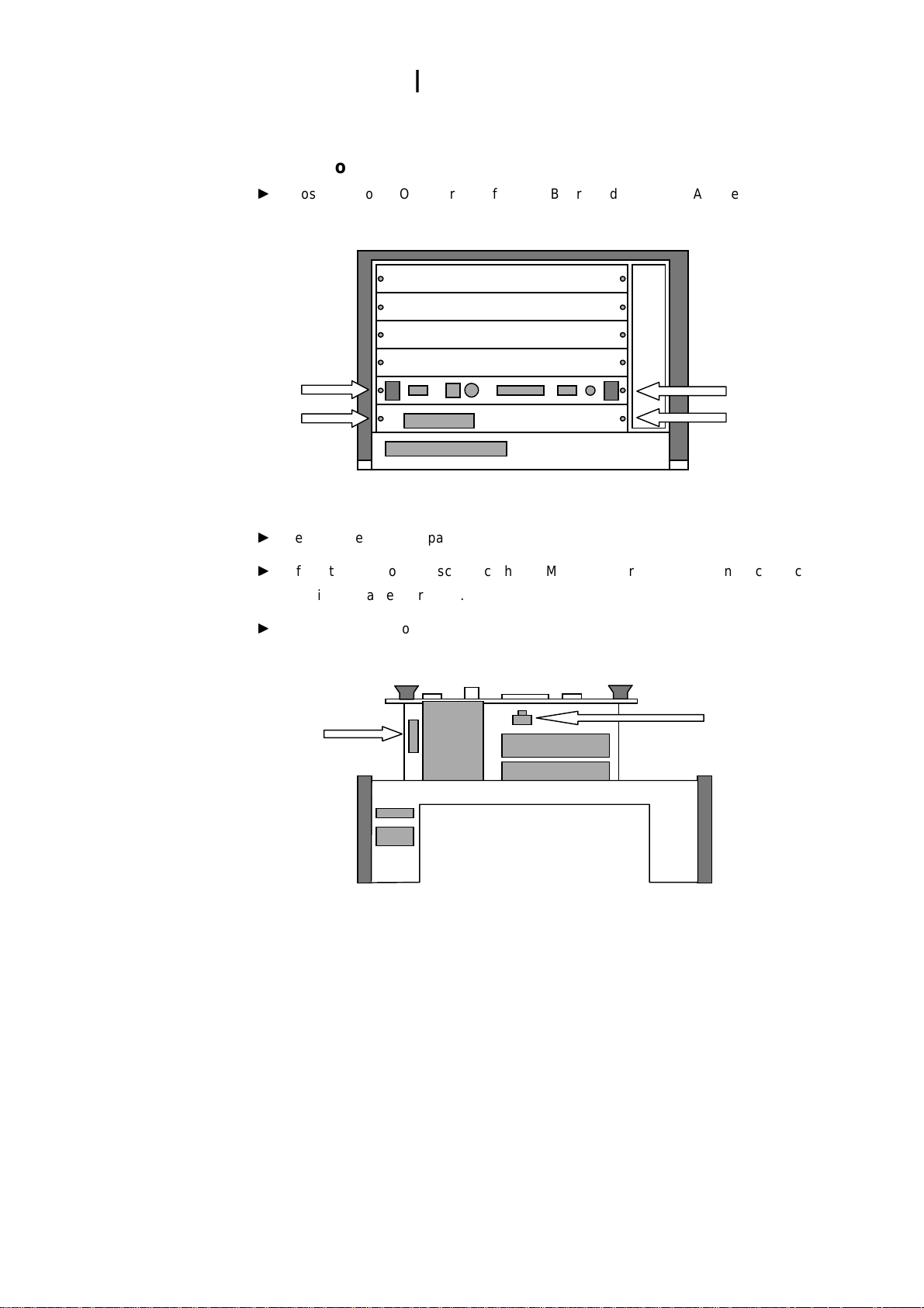
K12xx Bencht op :
►
To
remove the top cover lift up the four plastic caps to reach the screws.
►
On
the left side is the ISA-Bus-Board, there you have to disconnect the two
cables (Arrow) which are connected to the PC-Board.
isplay / Front
►
Loosen the four TORX screws of the PC-Board and the PCMCIA panel.
►
For more space remove the hard disk box loosening the four screws (Arrow A).
A
►
Remove the PCMCIA panel.
075-0667-00
3
Page 14

Hardware Installation
1
►
Disconnect the COM2 cable (Arrow A) from the PC-Board.
►
Lift up the PC-Board, disconnect the display cable (Arrow B),and remove the
board.
Note: ISA-Bus cables are still connected to the PC-Board and can be damaged.
A
B
►
Move the two ISA-Bus cable from the PC-3 to the PC-4 board.
►
Insert the PC-4 board and connect the display cable. Fix the cable using the
retainer.
►
Connect the COM2 cable (Arrow A) from the PCMCIA panel for PC-4 boards.
Note: The place and the direction of the connection has changed.
►
Fasten the screws of PC-4 board and PCMCIA panel.
A
►
If
you removed the hard disk box, insert it and fasten the screws.
►
Connect the both ISA-Bus cables.
►
Place the top cover and fasten the screws.
►
Add the label 7KK1200-6BC11 above the product label of the unit.
4
075-0667-00
Page 15
Hardware Installation
1
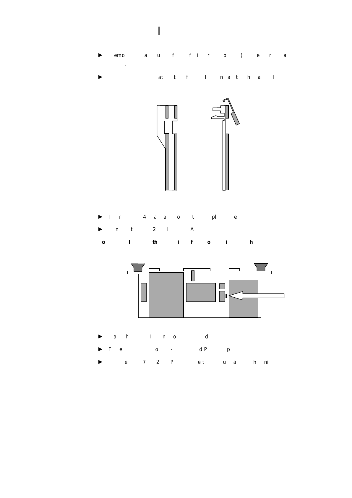
K12xx Portab le:
►
Loosen the four TORX screws of the PC-Board and the PCMCIA panel.
►
Remove the PCMCIA panel.
►
Lift up the PC-Board, disconnect the COM2 cable (Arrow A) and then disconnect
the display cable (Arrow B).
►
Remove the PC-Board.
A
B
075-0667-00
5
Page 16
Hardware Installation
1
►
Remove the card guide of the left side from Slot one (Temperature measuring
board).
►
Add the ground clip at the top of the rail and install it at the same place:
►
Insert the PC-4 board and connect the display cable.
►
Connect the COM2 cable (Arrow A).
Note: The place and the direction of the connection has changed.
►
Place the PCMCIA panel for PC-4 boards.
►
Fasten the screws of PC-4 board and PCMCIA panel.
►
Add the label 7KK1200-6PC11 above the product label of the unit.
A
6
075-0667-00
Page 17

PC-4 BIOS Setup
1
How to start:
The drive letter <E:\> for the CD-ROM is only a placeholder for CD-ROM drive,
please checkout the actual drive letter.
►
Switch off the K12xx
►
Connect CD-ROM drive to the external SCSI connector
►
Switch on the CD-ROM drive
►
Switch on the K12xx
BIOS Settings ( Date and Time ):
Setting of the hardware clock on the PC-4 board.
►
A
black screen titled Award Modular BIOS v4.51PG appears
►
Press DEL to enter BIOS setup
►
A
window appears titled as follows (first line might be slightly different):
ROM PCI ISA BIOS (2A69KEH0)
CMOS SETUP UTILITY
AWARD SOFTWARE, INC.
►
To
confirm STANDARD CMOS SETUP > press enter
►
Use the <Cursor Keys> to select the desired features
►
Use the < Page Up / Page Down Keys > to change the values
►
Set Date and Time
►
To
quit the BIOS Features Setup, press
<F10>
settings, press
►
Confirm the SAVE to CMOS and EXIT dialog with Y
►
The device will be restarted
for Save & Exit Setup
<ESC>.
To
take over the changed
075-0667-00
7
Page 18

PC-4 BIOS Setup
1
Symbios Configuration Settings ( narrow SCSI disk ):
Configuration of the hard disk controller for use of the internal installed hard disk.
►
A
black screen titled Award Modular BIOS v4.51PG appears
►
A
black screen titled LSI Logic Corp. SDMS (TM) V4.0 .... appears
►
Press Ctrl-C to start Symbios Configuration
►
Boot Adapter List appears > press enter
►
Adapter Properties appears > press enter
►
Device Properties appears
►
Move the highlighted cursor with the arrow keys to line of the hard disk and to
column MT/Sec
►
Change the value to 10 by using the function key Fn and using the white -/+ keys
►
Note the SCSI-ID for the Boot.ini modifications (should be ID:01)
►
Press ESC to exit
►
Adapter Properties appears > press ESC
►
Adapter and/or device properties.... appears
►
Select Save changes then exit this menu by using the arrow keys
►
Boot Adapter List appears > press ESC
►
Are you sure you want to exit ? appears
►
Select Exit the Configuration Utility by using the arrow keys
►
The device will be restarted
8
075-0667-00
Page 19

PC-4 Driver Installation
1
Display Driver:
Installation of the new display driver from the Tools CD.
►
Unit starts with the VGA –Graphics – Mode ( small window size )
Two additional error messages will appear on the screen:
a ) Service Control Manger window stating: wrong Network driver ( NE2000 )
b ) Invalid Display Setting window stating: wrong Graphics driver
The error messages will appear during boot until the following steps are
completed:
a) Network Driver, Service Pack 5 and update of the Application Software.
The network will not work properly during this phase.
b) Display Driver and Display Settings.
►
Insert the Tools CD into the CD-ROM drive.
►
Close all application and message windows apart from the Display Properties
window
►
Select Display Type
►
Display Type window > select Change
►
Change Display window > select Have Disk
►
Install From Disk window > enter E:\Driver\Display and confirm with OK
►
Change Display window > select Chips And Technologies and confirm with OK
►
Third-party Drivers window > confirm with Yes
►
Installing Driver window > confirm with OK
►
Display Type window > select Close
►
Display Properties window > select Close
►
System Settings Change window > confirm with No
075-0667-00
9
Page 20

PC-4 Driver Installation
2
Network Driver:
Installation of the new network driver from the Tools CD .
►
Select > Start – Settings – Control Panel
►
If
the window size is to large
►
Right click on the blue header of the Control Panel window
►
Select Maximize for a full screen
►
Select Network by double-clicking the left mouse button
►
In
the Network window change from Identification to Adapters
►
Select Remove and confirm the Warning window with Yes
►
Select Add....
►
Select Network Adapters window > select Have Disk
►
Insert Disk window enter E:\Driver\Net\D C21x4 and confirm with OK
►
Select OEM Option window appears
►
Select the driver ,Intel 21143based 10/100mpbs Ethernet Controller’ from the list
►
Confirm with OK
►
Intel 21143based ..... Controller Setup window > confirm with OK
►
Network window > select Close
►
Network Setting Change window > confirm with Yes
►
The device will be restarted
Display Settings:
Setting of the right driver properties for the installed display.
►
After the successful restart, close all application and message windows apart
from the Display Properties window
►
Select ‘1024 x 768 pixels at ‘Desktop area’
►
Select ’75 Hertz’ at ‘Refresh Frequency’
►
Control ‘256 colors‘ at ‘Color Palette‘
►
Control ‘Small Fonts’ at ‘Font Size’
►
Confirm with Apply
►
Display Settings window > confirm with OK
►
If
the window Display Properties is open close it with > OK
0
075-0667-00
Page 21

PC-4 Driver Installation
2
►
If
are the Icons not arranged, right click on the display and select Arrange Icons –
Auto Arrange
Note:
The following three steps are sensitive changes to the boot sequence of the unit. Any
missed step or fault will produce an error and cause the unit not to start.
By using the NT-Boot-Disk it is possible to repeat the single steps.
Symbios Driver:
Installation of the new driver for the hard disk controller, from floppy disk.
►
Insert floppy disk Symbios Driver for Windows NT V4.15
►
Select > Start – Settings – Control Panel
►
Control Panel window appears
►
Select SCSI Adapters by double-clicking the left mouse button
►
Change in the SCSI Adapter window from Devices to Drivers
►
Select Add...
►
Install Driver window > select Have Disk
►
Enter A:\winnt\miniport and confirm with OK
►
Confirm with OK
►
Windows NT Setup window > select New
►
Confirm with continue
►
System Settings Change window > select No
►
Close SCSI Adapters window with OK
►
Close Control Panel window
Copy the driver symc8xx.sys as follows:
This driver is necessary to provide access to SCSI-Mode which is used in the
Boot.ini.
►
Select > Start – Programs – Command Prompt
►
Command Prompt window appears
►
Type < copy a:\winnt\miniport\symc8xx.sys c:\ntbootdd.sys > and press enter
►
Close Command Prompt window
►
Remove the floppy disk
075-0667-00
1
Page 22

PC-4 Driver Installation
2
Edit C:\Boot.ini as foll o w s :
After these changes the hard disk controller will work in the SCSI-Mode.
►
Select My Computer icon by double-clicking the left mouse button
►
My
Computer window > Select Sys(C:) by double-clicking the left mouse button
►
Select Boot.ini with a right click and select Properties
►
boot.ini Properties window > unmark the box Read-Only and confirm with OK
►
Select Boot.ini by double-clicking the left mouse button and the boot.ini-Notepad
appears.
►
Change following Entries:
All multi to scsi
All values of disk from (0) to the SCSI-ID of the installed hard disk
the normal default is (1).
►
Example:
[boot loader]
timeout=5
default=scsi(0)disk(1)rdisk(0)partition(1)\WINNT
[operating systems]
scsi(0)disk(1)rd isk(0)partition(1)\WINNT="..........
scsi(0)disk(1)rd isk(0)partition(1)\WINNT="..........
►
Select File – Save
►
Select File – Exit
►
Select Boot.ini with a right click and select Properties
►
boot.ini Properties window > mark the box Read-Only and confirm with OK
►
Select > Start – Shut Down and select Shut down the Computer
►
Confirm with Yes
►
If
the window Shutdown Computer appears > select restart
►
The device will be restarted
2
075-0667-00
Page 23

Operati ng System Update
2
Based on Windows NT 4.0 with Service Pack 3:
Update Microsoft Data Access Components:
►
After the successful restart, close all application and message windows
►
Select My Computer icon by double-clicking the left mouse button
►
Open ‘Tools-CD’ with Tools (E:)
►
The TOOLS Setup Guide window appears
►
Select Readme and read the instructions
►
Install the Microsoft Data Access Components
►
If
the Microsoft Data Access 2.1 – Restart Window appears > select Exit
►
Warning message Setup not completed > confirm with OK
►
To
close the TOOLS Setup Guide > press ESC
Uninstal l Acrobat Reader V3.01:
►
Select > Start – Programs – Adobe Acrobat – Uninstall Acrobat Reader 3.01
►
Confirm File Deletion window > confirm with Yes
►
The Remove Programs From .... window appears
►
Wait for the message Uninstall successfully completed at bottom of the window
►
Confirm with OK
►
Select > Start – Shut Down and select Restart the Computer
►
Confirm with Yes
►
The device will be restarted
Install Acrobat Reader 4.0:
►
After the successful restart, close all application and message windows
►
Select My Computer icon by double-clicking the left mouse button
►
Open ‘Tools-CD’ with Tools (E:)
►
The TOOLS Setup Guide window appears again
►
Install the Acrobat Reader
►
If
the Information window appears > confirm with OK
►
Follow the instructions of the Service Pack 5, starting with point Install the
Screen Saver
075-0667-00
3
Page 24

Operati ng System Update
2
Based on Windows NT4.0 with Service Pack 5:
Install K12xx Screen Saver:
►
After the successful restart, close all application and message windows
►
Select My Computer icon by double-clicking the left mouse button
►
Open ‘Tools-CD’ with Tools (E:)
►
The TOOLS Setup Guide window appears
►
Install the Screen Saver
Update Microsoft Intern et Explorer V5.5:
►
Install the Microsoft Internet Explorer V5.5
►
If
the Restart Computer window appears > confirm with Finish
►
The device will be restarted
Screen Saver Settings:
►
After the successful restart, close all application and message windows
►
Right click on the display and select Display Properties
►
In
the Display Properties window change from Settings to Screen Saver
►
Select from the Screen Saver list box> K12xx Screen Saver and confirm with OK
Update Microsoft Window s NT 4.0 Service Pack 5:
►
Select My Computer icon by double-clicking the left mouse button
►
Open ‘Tools-CD’ with Tools (E:)
►
The TOOLS Setup Guide window appears
►
Install the Microsoft Windows NT 4.0 Service Pack 5
►
Confirm the Restart question if it appears
►
The device will be restarted
Now Update the drivers of the applicati on software
4
075-0667-00
Page 25

Applic ation System Update
2
K1205 Version 1.20 update:
►
After the successful restart, close all application and message windows
►
Remove the Tools-CD from the CD-ROM drive
►
Insert floppy disk: E138 Patch; Driver for E138 board for K1205 V1.20
►
Select > Start – Run and enter A:\setup.exe
►
E138 Driver Patch ... window > select Install
►
The Readme.txt window appears.
►
Close the Readme.txt window.
►
Setup window > confirm with OK
►
E138 Driver Patch ... window > select Finish
►
Follow the instructions of Clean up procedure
K1205 Version 2.0x update:
►
After the successful restart, close all application and message windows
►
Remove the Tools-CD from the CD-ROM drive
►
Insert floppy disk: E138 Patch; Driver for E138 board for K1205 V2.0x
►
Select > Start – Run and enter A:\install.cmd
►
Setup K1205 window > confirm with Next
►
Setup K1205 window > select Start
►
Setup K1205 window > confirm Finish
►
Close Readme.txt window
►
Remove floppy disk
►
K1205 Protocol Tester window > select Restart
►
The device will be restarted
►
After the successful restart, close all application and message windows
►
Insert floppy disk: E138 Boot Problems Patch; Patch for ‘reset.dll’ for K1205
V2.0x
►
Select > Start – Run and enter A:\Disk_Root\install.cmd
►
Setup K1205 window > confirm with Next
►
Setup K1205 window > select Start
►
Setup K1205 window > confirm Finish
075-0667-00
5
Page 26

Applic ation System Update
2
►
Close Readme.txt window
►
Remove floppy disk
►
K1205 Protocol Tester window > confirm with OK
►
Follow the instructions of Clean up procedure
K1297 Classic update:
►
After the successful restart, close all application and message windows
►
Select > Start – Run and enter Taskmgr.exe
►
Windows NT Task Manager window appears > select window Processes
►
Select in the list the file DIO.EXE and than press End Process
►
Task Manager Warning window > confirm with Yes
►
Close Task Manager window
►
Select My Computer icon by double-clicking the left mouse button
►
Open ‘Tools-CD’ with Tools (E:)
►
The TOOLS Setup Guide window appears
►
Install the TQ/DIO Driver for Microsoft Windows NT
►
To
close the TOOLS Setup Guide > press ESC
►
Remove the Tools-CD from the CD-ROM drive
►
Insert CD: K1297 Protocol Tester; System and Application Software V2.3x
►
Select > Start – Run and enter E:\Setup.exe
►
Welcome window > confirm with Next
►
Setup Types of K1297 window > select button for System Setup
►
Warning window > confirm with Next
►
Setup Complete window > confirm with Restart
►
Remove the K1297-CD from the CD-ROM drive
NOTE: After the first Reboot maybe the interfaces will not be configured,
please Reboot the unit a second time
►
Follow the instructions of Clean up procedure
6
075-0667-00
Page 27

Applic ation System Update
2
K1297-G20 update:
►
After the successful restart, close all application and message windows
►
Remove the Tools-CD from the CD-ROM drive and insert CD: K1297-G20,CD
Version V1.10
►
K1297-G20 Setup Guide window appears
►
Press button at the left bottom of the window and select End Show
►
Select > Start – Run and enter E:\Setup\K12xx_base.cmd
►
Setup – Wizard window > confirm with Start
►
Setup K1292-G20 Protocol Tester window > confirm with Restart
►
Follow the instructions of Clean up procedure
Clean Up Procedure:
►
Select > Start – Programs – Administrative Tools – Event Viewer
►
Event Viewer window > Open the Log menu
►
Select the options System, Security and Application step by step
and execute the next three steps for each.
►
Select from the Log menu > Clear All Events
►
Save event log > select No
►
Clear event log > select Yes
►
Close the Event Viewer window
►
Select > Start – Run and enter rdisk /s
►
Use the Emergency Repair Disk for this procedure
►
Remove floppy disk
►
Select > Start – Shut Down and select Shut down the Computer
►
Confirm with Yes
►
After next start no more error messages should appear and the event logs should
be free of warnings and errors.
075-0667-00
7
Page 28

Troubles hooting
2
Prerequisites:
System stops at the Windows NT boot sequence:
►
Use the created Windows NT - Boot Disk and check following points
►
Ntbootdd.sys is installed
►
Boot.ini settings
Windows NT screen is still small:
►
Enlarge the size to 1024 x 768 pixel at Display Properties
►
Wrong display driver is installed Chips & Technologies, install Chips And
Technologies
Stop messages in the Event Log, System:
►
Novell network diver could not started, remove the Novell driver at Network.
►
DC21x4 network driver could not started, install the application drivers as
described
K1297-G20 Software does not start:
►
Date or time is less then the last usage
►
Insert PC-3 again and enter the BIOS-Setup to note Data and Time
►
Insert PC-4 and compare or set new Date and Time
8
075-0667-00
075-0667-00
Page 29

2
9
 Loading...