

Page 1

J18
LumaColor II Photometer
Instruction Manual
070-9021-03
This document applies to firmware version 2.00
and above.
Warning
The servicing instructions are for use by qualified
personnel only. To avoid personal injury, do not
perform any servicing unless you are qualified to
do so. Refer to the Safety Summary prior to
performing service.
Page 2

Copyright E Tektronix, Inc. All rights reserved. T ektronix products are covered by U.S. and foreign patents, issued and
pending. Information in this publication supercedes that in all previously
published material. Specifications and price change privileges reserved.
Printed in the U.S.A.
T ektronix, Inc., P.O. Box 1000, Wilsonville, OR 97070–1000
TEKTRONIX and TEK are registered trademarks of T ektronix, Inc.
Page 3

EC Declaration of Conformity
We
T ektronix Holland N.V.
Marktweg 73A
8444 AB Heerenveen
The Netherlands
declare under sole responsibility that the
J18 LumaColor Photometer
meets the intent of Directive 89/336/EEC for Electromagnetic
Compatibility . Compliance was demonstrated to the following
specifications as listed in the official Journal of the European
Communities:
EN 50081–1 Emissions:
EN 55022 Radiated, Class B
EN 55022 Conducted, Class B
EN 60555–2 Power Harmonics
EN 50082–1 Immunity:
IEC 801–2 Electrostatic Discharge
IEC 801–3 RF Radiated
IEC 801–4 Fast Transients
IEC 801–5 Surge
Page 4

Page 5

WARRANTY
Tektronix warrants that this product will be free from defects in materials and
workmanship for a period of one (1) year from the date of shipment. If any such product
proves defective during this warranty period, Tektronix, at its option, either will repair the
defective product without charge for parts and labor, or will provide a replacement in
exchange for the defective product.
In order to obtain service under this warranty, Customer must notify Tektronix of the defect
before the expiration of the warranty period and make suitable arrangements for the
performance of service. Customer shall be responsible for packaging and shipping the
defective product to the service center designated by Tektronix, with shipping charges
prepaid. Tektronix shall pay for the return of the product to Customer if the shipment is to
a location within the country in which the Tektronix service center is located. Customer
shall be responsible for paying all shipping charges, duties, taxes, and any other charges for
products returned to any other locations.
This warranty shall not apply to any defect, failure or damage caused by improper use or
improper or inadequate maintenance and care. Tektronix shall not be obligated to furnish
service under this warranty a) to repair damage resulting from attempts by personnel other
than Tektronix representatives to install, repair or service the product; b) to repair damage
resulting from improper use or connection to incompatible equipment; or c) to service a
product that has been modified or integrated with other products when the effect of such
modification or integration increases the time or difficulty of servicing the product.
THIS WARRANTY IS GIVEN BY TEKTRONIX WITH RESPECT TO THIS
PRODUCT IN LIEU OF ANY OTHER WARRANTIES, EXPRESSED OR
IMPLIED. TEKTRONIX AND ITS VENDORS DISCLAIM ANY IMPLIED
WARRANTIES OF MERCHANTABILITY OR FITNESS FOR A PARTICULAR
PURPOSE. TEKTRONIX’ RESPONSIBILITY TO REPAIR OR REPLACE
DEFECTIVE PRODUCTS IS THE SOLE AND EXCLUSIVE REMEDY
PROVIDED TO THE CUSTOMER FOR BREACH OF THIS WARRANTY.
TEKTRONIX AND ITS VENDORS WILL NOT BE LIABLE FOR ANY
INDIRECT, SPECIAL, INCIDENTAL, OR CONSEQUENTIAL DAMAGES
IRRESPECTIVE OF WHETHER TEKTRONIX OR THE VENDOR HAS
ADVANCE NOTICE OF THE POSSIBILITY OF SUCH DAMAGES.
Page 6

Page 7

Table of Contents
General Safety Summary v. . . . . . . . . . . . . . . . . . . . . . . . . . . .
Service Safety Summary viii. . . . . . . . . . . . . . . . . . . . . . . . . . . . .
Preface ix. . . . . . . . . . . . . . . . . . . . . . . . . . . . . . . . . . . . . . . . . . . .
Getting Started
Product Description 1–1. . . . . . . . . . . . . . . . . . . . . . . . . . . . . . . . .
J18 LumaColor II Photometer Features 1–1. . . . . . . . . . . . . . . . .
Unpacking the J18 LumaColor II Photometer 1–2. . . . . . . . . . . .
Repackaging for Shipment 1–2. . . . . . . . . . . . . . . . . . . . . . . . . . . .
Power Options 1–3. . . . . . . . . . . . . . . . . . . . . . . . . . . . . . . . . . . . .
Low Battery Warning 1–3. . . . . . . . . . . . . . . . . . . . . . . . . . . . . . . . .
Battery Installation 1–4. . . . . . . . . . . . . . . . . . . . . . . . . . . . . . . . . . .
Using the Optional AC Power Adapter 1–5. . . . . . . . . . . . . . . . . . .
Functional Check 1–7. . . . . . . . . . . . . . . . . . . . . . . . . . . . . . . . . . .
Operating Basics
Functional Overview 2–1. . . . . . . . . . . . . . . . . . . . . . . . . . . . . . . .
J18 Front Panel 2–1. . . . . . . . . . . . . . . . . . . . . . . . . . . . . . . . . . . . .
J18 Control Descriptions and Operation 2–2. . . . . . . . . . . . . . . . . .
J18 Display 2–3. . . . . . . . . . . . . . . . . . . . . . . . . . . . . . . . . . . . . . . .
J18 Side Panel Connections 2–4. . . . . . . . . . . . . . . . . . . . . . . . . . . .
Tutorial 2–5. . . . . . . . . . . . . . . . . . . . . . . . . . . . . . . . . . . . . . . . . . .
Conditions 2–5. . . . . . . . . . . . . . . . . . . . . . . . . . . . . . . . . . . . . . . . .
Storing Measurements 2–6. . . . . . . . . . . . . . . . . . . . . . . . . . . . . . . .
Recalling Stored Measurements 2–7. . . . . . . . . . . . . . . . . . . . . . . .
Comparing Measurements 2–8. . . . . . . . . . . . . . . . . . . . . . . . . . . . .
J18 Photometer Instruction Manual
i
Page 8

Table of Contents
Reference
RS-232D Operation 3–1. . . . . . . . . . . . . . . . . . . . . . . . . . . . . . . . .
RS-232 Pin Connections 3–2. . . . . . . . . . . . . . . . . . . . . . . . . . . . . .
Syntax 3–3. . . . . . . . . . . . . . . . . . . . . . . . . . . . . . . . . . . . . . . . . . . .
Commands 3–7. . . . . . . . . . . . . . . . . . . . . . . . . . . . . . . . . . . . . . . .
Analog Output 3–9. . . . . . . . . . . . . . . . . . . . . . . . . . . . . . . . . . . . .
Location 3–9. . . . . . . . . . . . . . . . . . . . . . . . . . . . . . . . . . . . . . . . . . .
Specifications
Performance Verification
Maintenance
Service Strategy 6–1. . . . . . . . . . . . . . . . . . . . . . . . . . . . . . . . . . . .
Troubleshooting 6–3. . . . . . . . . . . . . . . . . . . . . . . . . . . . . . . . . . . .
Replaceable Parts
Replaceable Parts 7–1. . . . . . . . . . . . . . . . . . . . . . . . . . . . . . . . . . .
Parts Ordering Information 7–1. . . . . . . . . . . . . . . . . . . . . . . . . . . .
Using the Replaceable Parts List 7–1. . . . . . . . . . . . . . . . . . . . . . . .
Appendices
Appendix A: Photometry and Radiometry Reference A–1. . . . .
Photometric Relationships A–1. . . . . . . . . . . . . . . . . . . . . . . . . . . . .
Photometric Formulas A–2. . . . . . . . . . . . . . . . . . . . . . . . . . . . . . . .
Radiometric Relationships A–2. . . . . . . . . . . . . . . . . . . . . . . . . . . . .
Radiometric Formulas A–3. . . . . . . . . . . . . . . . . . . . . . . . . . . . . . . .
A Note on the Relation of Photometric and Radiometric Data A–3.
Appendix B: Chromaticity Reference B–1. . . . . . . . . . . . . . . . . .
The 1931 CIE Chromaticity Diagram B–2. . . . . . . . . . . . . . . . . . . .
The 1976 CIE-UCS Chromaticity Diagram B–6. . . . . . . . . . . . . . .
Spectral Tristimulus Values B–8. . . . . . . . . . . . . . . . . . . . . . . . . . . .
Glossary and Index
ii
J18 Photometer Instruction Manual
Page 9

List of Figures
Figure 1–1: Low Battery Warning Icon 1–3. . . . . . . . . . . . . . . . . . .
Figure 1–2: Replacing the Battery 1–4. . . . . . . . . . . . . . . . . . . . . . .
Figure 1–3: Location of J18 Power Adapter Connector 1–5. . . . . .
Figure 1–4: Initial Power-On Display 1–7. . . . . . . . . . . . . . . . . . . .
Figure 1–5: Typical Display Test 1–8. . . . . . . . . . . . . . . . . . . . . . . .
Figure 1–6: Typical Firmware Version Display 1–8. . . . . . . . . . . . .
Figure 1–7: Typical Zero Display 1–9. . . . . . . . . . . . . . . . . . . . . . .
Figure 1–8: T ypical Color Chromaticity Display 1–9. . . . . . . . . . .
Figure 1–9: T ypical Single Channel Display 1–10. . . . . . . . . . . . . . .
Figure 1–10: Sensor Head Missing or Not Recognized Display 1–10
Figure 2–1: Measurement with HOLD 2–6. . . . . . . . . . . . . . . . . . .
Figure 2–2: Selecting a Reference Memory Position 2–7. . . . . . . .
Figure 2–3: Typical Differential Measurement Display 2–8. . . . . .
Figure 3–1: Location of the RS-232D Port 3–1. . . . . . . . . . . . . . . .
Figure 3–2: RS-232 Pin Connections 3–2. . . . . . . . . . . . . . . . . . . .
Figure 3–3: Sample Measurement Message 3–3. . . . . . . . . . . . . . .
Figure 3–4: Location of the Analog Output 3–9. . . . . . . . . . . . . . .
Table of Contents
Figure 6–1: Test Point Locations on the A1 Board 6–6. . . . . . . . . .
Figure 7–1: J18 Replaceable Parts 7–3. . . . . . . . . . . . . . . . . . . . . . .
Figure 7–2: J18 Optional Accessories 7–4. . . . . . . . . . . . . . . . . . . .
Figure B–1: The 1931 CIE Chromaticity Diagram B–3. . . . . . . . . .
Figure B–2: 1931 CIE Chromaticity Diagram Showing Color
T emperature B–4. . . . . . . . . . . . . . . . . . . . . . . . . . . . . . . . . . . . .
Figure B–3: Correlated Color T emperature Diagram B–5. . . . . . . .
Figure B–4: 1976 CIE-UCS Chromaticity Diagram B–7. . . . . . . . .
Figure B–5: Spectral Tristimulus Values for Equal Spectral Power
Source (CIE 1931 Standard 2° Observer) B–8. . . . . . . . . . . . . .
J18 Photometer Instruction Manual
iii
Page 10

T able of Contents
List of Tables
Table 2–1: Factory Preset 6500 K White Values 2–9. . . . . . . . . . .
T able 3–1: RS-232D Parameters 3–1. . . . . . . . . . . . . . . . . . . . . . .
T able 3–2: Measurement Units 3–4. . . . . . . . . . . . . . . . . . . . . . . . .
T able 3–3: J18 Command Syntax 3–5. . . . . . . . . . . . . . . . . . . . . . .
T able 3–4: J18 Command Set 3–7. . . . . . . . . . . . . . . . . . . . . . . . . .
T able 3–5: Analog Output Specifications 3–10. . . . . . . . . . . . . . . . .
T able 4–1: Warranted Electrical Specifications 4–1. . . . . . . . . . . .
T able 4–2: Typical Electrical Specifications 4–1. . . . . . . . . . . . . .
T able 4–3: Warranted Environmental Specifications 4–2. . . . . . . .
T able 4–4: Typical Mechanical Specifications 4–2. . . . . . . . . . . . .
T able 4–5: Warranted Sensor Ranges 4–3. . . . . . . . . . . . . . . . . . . .
T able B–1: Spectral Tristimulus Values for Equal Spectral Power
Source (CIE 1931 Standard 2° Observer) B–9. . . . . . . . . . . . . .
iv
J18 Photometer Instruction Manual
Page 11

General Safety Summary
Review the following safety precautions to avoid injury and prevent
damage to this product or any products connected to it.
Only qualified personnel should perform service procedures.
Injury Precautions
Do Not Operate in Wet/Damp Conditions
To avoid electric shock, do not operate this product in wet or damp
conditions.
Do Not Operate in Explosive Atmosphere
To avoid injury or fire hazard, do not operate this product in an
explosive atmosphere.
Wear Eye Protection
To avoid eye injury, wear eye protection if there is a possibility of
exposure to high-intensity rays.
Product Damage Precautions
Use Proper Power Source
Do not operate this product from a power source that applies more
than the voltage specified.
Do Not Operate With Suspected Failures
If you suspect there is damage to this product, have it inspected by
qualified service personnel.
J18 Photometer Instruction Manual
v
Page 12

General Safety Summary
Do Not Immerse in Liquids
Clean the probe using only a damp cloth. Refer to cleaning
instructions.
Safety Terms and Symbols
Terms in This Manual
These terms may appear in this manual:
WARNING. Warning statements identify conditions or practices that
could result in injury or loss of life.
CAUTION. Caution statements identify conditions or practices that
could result in damage to this product or other property .
Terms on the Product
These terms may appear on the product:
DANGER indicates an injury hazard immediately accessible as you
read the marking.
WARNING indicates an injury hazard not immediately accessible as
you read the marking.
CAUTION indicates a hazard to property including the product.
vi
J18 Photometer Instruction Manual
Page 13

General Safety Summary
Symbols on the Product
The following symbols may appear on the product:
DANGER
High Voltage
Protective Ground
(Earth) T erminal
ATTENTION
Refer to
Manual
Double
Insulated
J18 Photometer Instruction Manual
vii
Page 14

Service Safety Summary
Only qualified personnel should perform service procedures. Read
this Service Safety Summary and the General Safety Summary before
performing any service procedures.
Do Not Service Alone
Do not perform internal service or adjustments of this product unless
another person capable of rendering first aid and resuscitation is
present.
viii
J18 Photometer Instruction Manual
Page 15

Preface
This manual contains information to support user operation and
service of the J18 LumaColor II Photometer.
The manual is divided into User and Service sections that are
separated by a yellow page.
User Information
The user information details the control and operation of the
photometer. This section also provides detailed information for the
analysis of the photometer readings. The user information is divided
into four chapters:
H Getting Started
H Operating Basics
H Reference
H Specifications
Service Information
The service section details user-level maintenance and repair of the
photometer.
H Performance Verification
H Maintenance
H Replaceable Parts
H Appendices
H Glossary and Index
J18 Photometer Instruction Manual
ix
Page 16

Preface
x
J18 Photometer Instruction Manual
Page 17

Getting Started Getting Started
Page 18

Page 19

Product Description
The J18 is a digital photometer, radiometer, and colorimeter. The
interchangeable J1800 series sensor-heads provide the ability to
make a variety of light measurements.
J18 LumaColor II Photometer Features
The J18 provides the following features:
H Real-time color measurements
H Auto zero
H Readings in either English or metric units
H RS-232D interface for remote control
H Interchangeable heads for future expansion
H Battery or AC-powered operation (AC adapter available as an
optional accessory)
H Backlighted display
H Analog output
J18 Photometer Instruction Manual
1–1
Page 20

Product Description
Unpacking the J18 LumaColor II Photometer
This section describes the accessories that are shipped with the J18.
If the contents of the shipping container are incomplete or damaged,
contact your T ektronix representative.
The J18 LumaColor II Photometer is shipped with the following
equipment:
H J18 LumaColor II Photometer
H Instruction Manual (this manual)
H Alkaline battery (Installed)
IEC type 6LR61, NEDA type 1604
Repackaging for Shipment
If you must ship the J18 or one of the J1800 series sensor heads,
package it as follows:
1. Use the original carton, or an equivalent carton with dimensions
at least three inches greater than the instrument to allow for
proper cushioning.
1–2
2. Cover the instrument with a polyethylene bag to protect its finish.
3. Cushion the instrument on all sides with packing material. Seal
the carton with shipping tape or with an industrial stapler.
4. If you are shipping the product to a T ektronix Service Center, be
sure to label the carton with the name of your company, a person
to contact at your company, and a description of the problem.
J18 Photometer Instruction Manual
Page 21

Power Options
The J18 may be powered by either of two sources:
H A non-rechargeable nine-volt alkaline battery
H An external AC power adapter, available as an optional
accessory. (See the Replaceable Parts section for information
about available accessories.)
NOTE. When switching between power sources, cycle the photometer
power off and then on again to enable the photometer to auto-zero
using the new power source.
Low Battery Warning
When battery voltage is below 7.2 volts, the J18 displays the flashing
warning battery icon in the upper left corner of its display. At this
point, you should replace the battery (see Figure 1–1).
The battery icon flashes
when the battery voltage
drops below 7.2 V.
+–
HOLD REF
Figure 1–1: Low Battery Warning Icon
If the battery voltage is below 7.2 volts at initial power-on, the J18
will not complete the self-test.
J18 Photometer Instruction Manual
1–3
Page 22

Power Options
Battery Installation
CAUTION. Follow the manufacturers’ guidelines for the handling and
disposal of batteries.
To replace the alkaline battery (refer to Figure 1–2):
1. Turn off the J18.
2. Open the battery compartment located on the back cover of
the J18.
3. Remove the old battery, and replace it with a new one. Arrange
the wires so that they will not interfere with the battery cover.
4. Close the battery compartment.
5. Turn on the J18 and make sure that the low-battery warning is
not flashing.
1–4
Figure 1–2: Replacing the Battery
J18 Photometer Instruction Manual
Page 23

Using the Optional AC Power Adapter
The J18 may be powered with the optional external AC power
adapter. The power adapter will override the internal battery if one
is installed. T o ensure accurate measurements, cycle the photometer
power off and then on again to permit the photometer to autozero
using the new power source.
Plug the pin connector of the adapter into the EXT. POWER
connector on the side of the J18 (see Figure 1–3). Plug the power
adapter into a 120 VAC AC power outlet. (A 220 V AC adapter is
also available.)
S
Power Options
ANALOG
+
OUTPUT
RS232D
Figure 1–3: Location of J18 Power Adapter Connector
CAUTION. Be sure that any power supply you use with the J18
provides power within the range of 9 to 16 VDC. Also, the center
contact polarity of the adapter is positive (+). A power supply that
does not meet these requirements may damage the J18.
The backlight will be lit at power-on when the J18 is powered by the
AC power adapter. The backlight may be turned off, if desired, by
pressing the BACKLIGHT button.
NOTE. AC power adapters that provide less than 12 volts may not
automatically turn on the backlight.
J18 Photometer Instruction Manual
1–5
Page 24

Power Options
1–6
J18 Photometer Instruction Manual
Page 25

Functional Check
The J18 performs a self-test when first turned on. The self-test is
successfully completed under the following conditions:
H A “fresh” battery must be installed, or the AC adapter must be
attached.
H A recognized sensor head must be attached. (The J18 will not
recognize the J1820 sensor head.)
1. Cover the sensor to block out any light before turning on power
to the J18.
2. When power is initially turned on, the display reminds you to
cover the sensor; see Figure 1–4. If the sensor is uncovered, the
display flashes and the self-test does not continue.
Figure 1–4: Initial Power-On Display
NOTE. If the photometer is turned on with the sensor uncovered,
cover the sensor and cycle the photometer power off and then on
again. This procedure ensures a complete photometer auto-zero.
J18 Photometer Instruction Manual
1–7
Page 26

Functional Check
3. After the auto-zero is complete, all of the display characters are
shown as a display test. See Figure 1–5.
+
–
+–
+
-
+
-
+
-
Figure 1–5: Typical Display Test
4. After the display test is complete, the display shows the firmware
version that is installed. See Figure 1–6.
1–8
Figure 1–6: Typical Firmware Version Display
J18 Photometer Instruction Manual
Page 27

Functional Check
5. After the firmware version is displayed, the photometer initially
displays zeros until the sensor cover is removed. See Figure 1–7.
Figure 1–7: Typical Zero Display
6. Remove the cover from the sensor head and aim the sensor to
take a measurement. If the sensor head is a multi-channel sensor,
the photometer displays the measurement in the selected color
coordinate system. See Figure 1–8.
Figure 1–8: Typical Color Chromaticity Display
J18 Photometer Instruction Manual
1–9
Page 28

Functional Check
If the attached sensor head is a single channel sensor, the photometer
displays only one value for the measurement. See Figure 1–9.
Figure 1–9: Typical Single Channel Display
7. If a sensor head is not attached, or the sensor head is not
recognized, the J18 flashes the error message shown in
Figure 1–10.
1–10
Figure 1–10: Sensor Head Missing or Not Recognized Display
J18 Photometer Instruction Manual
Page 29

Operating Basics Operating Basics
Page 30

Page 31

Functional Overview
This section provides a overview of the controls, indicators, and
operation of the photometer.
J18 Front Panel
Connect a J1800 Series
All readings appear
on the display. See
page 2–3.
Press the BACKLIGHT
button to light the display.
sensor head here.
The POWER switch
turns the J18 on or
off. The J18 performs
a brief self-test at
power-on.
Location of battery
J18 Photometer Instruction Manual
(Rear Panel)
compartment.
2–1
Page 32

Functional Overview
J18 Control Descriptions and Operation
Press the HOLD/RUN button to “freeze” measurements during
normal operation. Press the HOLD/RUN button to resume
measurements or to end differential measurements.
Press the RANGE HI/LO button to change the sensitivity of the
photometer when using single-channel sensors. The photometer
display will flash if the light level is too high.
Press the DIFF REF button to perform color difference
measurements when using the J1810 sensor. Pressing the DIFF
REF button again steps the photometer through the reference
memory locations.
Press the UNITS button to change the measurement units. The
measurement units available are determined by the sensor head.
Press the STORE button to store a measurement. Stored
measurements can be recalled for differential measurements or
later analaysis. (J1810 only)
2–2
Press the ALT DISPLAY button to change coordinate systems
when using a color sensor head. The ALT DISPLAY button will
have no effect with other heads. Refer to Appendix B for
information on color coordinate systems.
J18 Photometer Instruction Manual
Page 33

J18 Display
Functional Overview
The low battery icon
flashes when the battery
voltage is low.
See page 1–3.
+
+
-
+
-
+
–
The bar graphs display the relative
level of the input signal as compared
to the stored REFerence signal in
the differential mode.
-
The HOLD icon is
displayed when
measurements have
been interrupted.
+–
The REF icon is
displayed when the J18
is in the store or
differential measurement
mode.
The reference memory
location is displayed
when the J18 is in the
store or differential
measurement mode.
The color coordinate
system in use is
displayed on the right
side. (J1810 only)
Measurement units are
displayed in the lower
right corner.
Measurements are displayed
as numerical values in the
center of the display.
J18 Photometer Instruction Manual
2–3
Page 34

Functional Overview
J18 Side Panel Connections
9 to 16VDC
50mA MAX
ANALOG
OUTPUT
RS232D
Connect the optional
AC adapter here.
See page 1–5.
The analog output output
samples the amplifier
output before the A-to-D
converter. See page 3–9.
Connect the optional
RS-232 cable here for data
logging to a computer.
See page 3–1.
2–4
J18 Photometer Instruction Manual
Page 35

Tutorial
This section lists step-by-step instructions for storing and comparing
color measurements.
Conditions
Before operating the photometer, it must meet the following
conditions:
H Sensor head installed
H Power on
H Self-test completed without errors or low-battery indication
Refer to the J1800 Series LumaColor Photometer Sensor Heads
Technical Reference for specific turn-on procedures.
J18 Photometer Instruction Manual
2–5
Page 36

Tutorial
Storing Measurements
NOTE. The STORE button will only work with the J1810 sensor head.
1. Press the HOLD/RUN button to stop the measurement. See
Figure 2–1.
2–6
Figure 2–1: Measurement with HOLD
2. Press the DIFF/REF button to select the differential measure-
ment mode.
J18 Photometer Instruction Manual
Page 37

Tutorial
3. Repeatedly press the DIFF/REF button to select the desired
reference memory location. The reference location is shown on
the top of the display. See Figure 2–2. Readings can be stored
only in reference locations 1 to 10.
Figure 2–2: Selecting a Reference Memory Position
4. Press the STORE button to store the measurement. After storing
the measurement, the photometer goes into the differential
measurement mode. T o return to absolute readings, press the
HOLD/RUN button to clear the differential display.
Recalling Stored Measurements
T o view the values stored in the memory locations, perform the
following steps:
1. Press the DIFF/REF button to select the differential measure-
ment mode.
2. Repeatedly press the DIFF/REF button to step to the desired
reference memory location.
3. Press the ALT/DISP button so that the memory location begins to
flash and the display indicates the values stored in the memory
location.
4. Press the HOLD/RUN button to return to the differential
measurement mode.
J18 Photometer Instruction Manual
2–7
Page 38

Tutorial
5. Press the HOLD/RUN button again to return to the direct
measurement mode.
Comparing Measurements
NOTE. The DIFF/REF button will only work with the J1810
sensor-head.
Press the DIFF/REF button to enter the differential mode.
Repeatedly press the DIFF/REF button to step to a reference
memory location.
The differential mode displays the differences between the current
and stored values. The color bars on the left side of the display show
the relative color differences of the red, green, and blue components.
The numeric display indicates the magnitude differences in the
color-coordinate system. See Figure 2–3.
2–8
+
–
Figure 2–3: Typical Differential Measurement Display
NOTE. The bargraphs are nonlinear to provide impr oved resolution
when approaching the reference values.
J18 Photometer Instruction Manual
Page 39

Tutorial
Factory-stored reference values for video display white levels are
stored in memory locations 12 to 19. Use these values to adjust
displays to 6500 K white at standard luminance values. Refer to
T able 2–1 for luminance values and memory locations.
Table 2–1: Factory Preset 6500K White Values
Memory
Location
12 5 17.1
13 15 51.4
14 20 68.5
15 25 85.7
16 30 103
17 35 120
18 40 137
19 50 171
fL cd/m
2
The factory-stored reference levels support all units and coordinate
systems.
To take dif ferential measurements using the factory-stored reference
values, perform the following steps:
1. Press the DIFF/REF button to select the differential measure-
ment mode.
2. Repeatedly press the DIFF/REF button to step to the desired
reference memory location.
3. Press the HOLD/RUN button to exit the differential mode.
4. Select the desired units and coordinate system using the UNITS
and ALT DISP buttons.
5. Press the DIFF/REF button to display the difference measure-
ment using the reference value selected in step 2.
J18 Photometer Instruction Manual
2–9
Page 40

Tutorial
2–10
J18 Photometer Instruction Manual
Page 41

Reference Reference
Page 42

Page 43

RS-232D Operation
You can use the J18 LumaColor II Photometer’s RS-232D port to
remotely control the photometer and to save measurement readings
to a file on a computer. All of the functions of the front panel control
can be duplicated through the RS-232D port.
Figure 3–1: Location of the RS-232D Port
The J18 operates with the RS-232 parameters shown in T able 3–1.
The terminal or computer you connect to the J18 must match these
parameters in order to communicate using the RS-232 port. Also, the
terminal should be set with the local echo turned on.
RS232D
The RS-232D Port
Table 3–1: RS-232D Parameters
Parameter Value
Baud Rate 2400
Data Bits 8
Stop Bits 1
Data Type Asynchronous
Operational Mode Half-duplex (accepts software flow control)
J18 Photometer Instruction Manual
3–1
Page 44

RS-232D Operation
RS-232 Pin Connections
An RS-232 cable is available as an optional accessory to the J18
(refer to Replaceable Parts for ordering information). This cable has
a 3.5 mm connector for the J18, and a DB-9 female connector for
connection to the computer. (Another common RS-232 connector on
computers is the DB-25 connector. Adapters are commercially
available to convert from the DB-9 connector to a DB-25 connector.)
Figure 3–2 shows the pin connections of the J18 RS-232 port and the
optional RS-232 cable.
3.5 mm Stereo Phone Plug
12 3
Figure 3–2: RS-232 Pin Connections
Ground
Receive
Transmit
RS-232
5
9
4
8
3
7
2
6
1
DB-9
(Female)
3–2
J18 Photometer Instruction Manual
Page 45

Syntax
The data format for measurements consists of a units notation,
followed by the floating-point measurement value. Values are
displayed with four significant digits, and a one-digit exponent with
an optional minus sign. For multiple values. See Figure 3–3.
Figure 3–3: Sample Measurement Message
Each line is terminated by a carriage return and line feed (CR/LF).
!NEW
x = 0.100E0 y = 0.331E0 LUM = 34.65E–3 cd/m^2
J18 Photometer Instruction Manual
3–3
Page 46

Syntax
T able 3–2 lists the abbreviations the J18 uses when reporting
measurement units over the RS-232D interface.
Table 3–2: Measurement Units
Abbreviation
cd candelas
cd/m^2 candelas/meter
fc foot-candles
fL foot-lamberts
K kelvins
Lux lux
W watts
W/m^2 watts/meter
W/m^2/sr watts/meter2/steradian
X, Y, Z 1931 CIE tristimulus values
u‘, v‘ 1976 CIE-UCS color coordinate system
x, y, units 1931 CIE color coordinate system
Usage
2
2
3–4
J18 Photometer Instruction Manual
Page 47

Syntax
T able 3–3 summarizes the syntax conventions of the command set.
Table 3–3: J18 Command Syntax
Symbol
! Begins command. (All commands should be prefaced with
{CR} Carriage return (ASCII 13); recognized as an end-of-com-
{LF} Line feed (ASCII 10); also recognized as an end-of-com-
(white space) Spaces act as parameter delimiters within commands. The
italics Items in italics are names of parameters. Specify the
Meaning
an exclamation point.)
mand delimiter.
mand delimiter.
J18 also recognizes commas (,) and tabs as parameter
delimiters; any of these three characters may be used
interchangeably.
appropriate value when entering the command.
J18 Photometer Instruction Manual
3–5
Page 48

Syntax
3–6
J18 Photometer Instruction Manual
Page 49

Commands
The J18 LumaColor II Photometer recognizes ten commands that
duplicate the function of the front panel controls. These commands
are summarized in T able 3–4.
NOTE. The J18 is a case-sensitive device, so all RS-232 commands
should be made in capital letters (upper-case), for example: !NEW.
Table 3–4: J18 Command Set
Command
!INI{CR} Initializes the instrument. Puts the J18 in the initial
!ALT{CR} Same as the ALT DISP button.
!BKL{CR} Same as the BACKLIGHT button.
!DIF{CR} Same as the DIFF/REF button.
!HLD{CR} Same as the HOLD button.
!RGE{CR} Same as the RANGE HI/LO button.
!STR{CR} Same as the STORE button.
!UNT{CR} Same as the UNITS button.
!NEW{CR} Causes the J18 to report the last measurement taken.
!NEW n {CR} Causes the J18 to report the specified number
Function
powerup state with no valid data for the attached sensor
head.
(n = sample size) of measurements beginning with the
last one taken. The sample size may be from 1 to 255. A
value of n ≥ 128 or greater causes the J18 to report
measurements continuously until another command is
sent.
J18 Photometer Instruction Manual
3–7
Page 50

Commands
3–8
J18 Photometer Instruction Manual
Page 51

Analog Output
The J18 features an uncalibrated analog output for use with auxillary
equipment such as strip chart recorders and analog meters. The
analog output is driven by the “Y” luminance channel. This is the
same channel that is used for single-channel sensor heads.
The analog output samples the J18 amplifier output before it goes to
the D to A converter. Table 3–5 lists the analog output specifications.
Location
The analog output jack is located on the right side panel of the J18.
Figure 3–4: Location of the Analog Output
J18 Photometer Instruction Manual
Analog Output
3–9
Page 52

Analog Output
Table 3–5: Analog Output Specifications
Characteristic
Connection 2.5 mm phone plug, center conductor positive (+)
Time Constant 100 ms
Output Level
(typical)
Output Impedance
(typical)
Standard
0 to +5 VDC
100 kW
3–10
J18 Photometer Instruction Manual
Page 53

Specifications Specifications
Page 54

Page 55

Specifications
T ables 4–1 through 4–5 list the specifications of the J18. Warranted
specifications are guaranteed to the customer. Typical specifications
are provided for customer convenience and may change.
Table 4–1: Warranted Electrical Specifications
Characteristic Standard
Accuracy 1% of reading ±2 count
Emissions EN 50082-1 when used with Tektronix power supply and
EMI Immunity EN-50082-1
ESD Immunity Up to 8kV
Table 4–2: Typical Electrical Specifications
(Excluding sensor nonlinearity)
RS-232 cable.
Characteristic
Power
Requirements
Battery Life
(Typical)
Low Battery
Indicator
Standard
Alkaline battery, 7 to 10V
External Power Supply, 9 to 16VDC
30 hours
(IEC 6LR61 battery with backlight off and
RS-232 unplugged)
7.2 V
J18 Photometer Instruction Manual
IEC 6LR61
NEDA 1604
4–1
Page 56

Specifications
Table 4–3: Warranted Environmental Specifications
Characteristic
Temperature Nonoperating: –55°C to +85°C
Humidity Nonoperating: 97%, +30°C to +60°C
Standard
Operating: –15°C to +55°C
Per Tek Std 062–2847–00
Operating: 97%, +30°C to +55°C
Table 4–4: Typical Mechanical Specifications
Characteristic
Dimensions Height: 198 mm (8 inches)
Weight 1.4 kg (3 pounds)
Standard
Width: 93 mm (3.7 inches)
Depth: 34 mm (1.3 inches)
4–2
J18 Photometer Instruction Manual
Page 57

Specifications
Table 4–5: Warranted Sensor Ranges
Sensor Range
J1803 0.3 to 300,000 cd/m2 (nit)
0.1 to 100,000 fL
J1805 0.01 mcd to 10 cd
J1806 0.001 to 200 W/m2/sr
J1810 0.001 to 0.999 xy and u’v’ coordinates (above 3 cd/m2)
2
0.3 to 1000 cd/m
(nit)
0.1 to 300 fL
J1811 0.1 to 5000 lux (lm/m2)
0.1 to 500 fc
J1812 0.1 to 2000 mW/m
2
10 nW to 0.2 mW
J1823
(Standard version)
J1823
(Option 01)
3 to 3,000 cd/m2 (nit)
1 to 10,000 fL
30 to 30,000 cd/m2 (nit)
10 to 10,000 fL
J18 Photometer Instruction Manual
4–3
Page 58

Specifications
4–4
J18 Photometer Instruction Manual
Page 59

WARNING
The following servicing instructions are for use only by
qualified personnel. To avoid injury, do not perform any
servicing other than that stated in the operating instructions
unless you are qualified to do so. Refer to all Safety
Summaries before performing any service.
Page 60

Page 61

Performance Verification Performance Verification
Page 62

Page 63

Performance Verification
Performance verification procedures are included in the manual
shipped with the J1800 series sensor-heads. If you are checking
sensor-heads formerly used with a J17, the J17 verification procedure
may be used.
NOTE. The J1820 chromaticity sensor-head will not work with the
J18. The J1820 sensor-head will only work with the J17
LumaColor photometer.
J18 Photometer Instruction Manual
5–1
Page 64

Performance Verification
5–2
J18 Photometer Instruction Manual
Page 65

Maintenance Maintenance
Page 66

Page 67

Service Strategy
The J18 is user serviceable to the circuit-board level. Certain
cosmetic parts and connectors may also be replaced by the customer.
A list of replaceable parts is in the Replaceable Parts chapter.
Basic Troubleshooting lists some operating conditions to check for if
you believe the photometer or the sensor-head is not operating
correctly .
Board-level Troubleshooting will allow you to isolate most problems
to one of the two replaceable circuit boards in the photometer. Use
these procedures if you want to repair the photometer yourself.
There are no user-adjustments in the J18.
J18 Photometer Instruction Manual
6–1
Page 68

Service Strategy
6–2
J18 Photometer Instruction Manual
Page 69

T roubleshooting
If the J18 LumaColor II Photometer or one of the J1800 Series
sensor heads does not appear to function correctly, the information in
this section will help you isolate the problem.
Basic Troubleshooting
This section lists some common problems and their most likely
causes.
The J18 Does Not Power On, or Backlight Does Not Light
Check the battery. Install a fresh battery, and ensure that it is seated
correctly . If the optional AC adapter is available, use it to connect
the J18 to a power source.
Measurements are Inaccurate
If measurements taken with the J18 are inaccurate or inconsistent,
check the operating setup:
H Did you connect the sensor head to the J18 before power-on? If
not, turn the J18 off, cover the sensor–head, and then turn the J18
back on. The J18 will load data from a sensor head at power-on.
H For luminance, radiance, and chromaticity measurements, make
sure that the sensor head is positioned so that the measurement
field is entirely filled by the surface to be measured.
H For luminance, radiance, and chromaticity measurements, make
sure that the area being viewed by the sensor head is uniformly
illuminated.
H Shadowing will occur if the surface is being measured from
direction of the illumination. Position the sensor head so that it
does not shadow the surface being measured.
J18 Photometer Instruction Manual
6–3
Page 70

Troubleshooting
H Operating the sensor-head in contact with the surface is not
recommended, because reflections may occur between the front
surface of the head and the surface to be measured. Placement of
the head too close to the surface may also cause shadowing.
The light shield or suction cup provides adequate spacing
between the head and the surface to prevent reflection on
backlighted surfaces.
If measurements are still incorrect, the sensor head may require
recalibration. Contact your T ektronix representative.
Board-level Troubleshooting
The two circuit boards in the J18 may be replaced. If the J18 does
not function, you can use these procedures to isolate the problem to
one of the boards. Refer to Replaceable Parts for ordering information.
CAUTION. The following servicing instructions are for use by
qualified service personnel only. Once the covers of the J18 are
removed, the instrument could be damaged.
6–4
Most functions of the J18 are located on the A1 board. The A2
Display board controls the display, backlight, and keyboard. The
general troubleshooting sequence for the J18 is:
1. Verify that the problem is not covered in Basic Troubleshooting.
2. Check for a display, backlight, or keyboard problem (indicating
the A2 board). If there appears to be a display problem, also
check the power supply on the A1 board, which could be at fault.
3. Other problems are due to the A1 board. If a power supply
problem is suspected, perform the procedure in Checking the
Power Supply to verify that the power supply, and not the battery,
is at fault.
J18 Photometer Instruction Manual
Page 71

Troubleshooting
The A1 Board
Most functions of the J18 are located on the A1 board. Checking the
Power Supply, later in this section, will allow you to determine
whether there is a power supply problem.
The A2 Display Board
The A2 Display board is probably at fault if:
H segments of the display are missing
H the backlight does not operate
T o check the display, power on the J18 without a sensor head
attached, and note whether all segments of the display are activated.
If the entire display is inactive, or if the backlight does not operate,
proceed to Checking the Power Supply to rule out a problem with the
power supply.
Checking the Power Supply
T o check the power supply, you will need:
3
/32inch hex wrench
H
H Pozidriv screwdriver
H a voltmeter (for voltages in the range 0 to 15 V)
H Nine-volt, IEC 6LR61-type alkaline battery
1. Remove the battery from the battery compartment.
CAUTION. Do not apply power to the J18 while disassembling it.
Damage to the A2 board could result.
Static electricity can damage the circuit boards of the J18. Observe
static precautions when the covers of the J18 are removed.
2. Using the hex wrench, remove the four screws from the J18 front
panel.
3. Remove the back cover of the J18.
J18 Photometer Instruction Manual
6–5
Page 72

Troubleshooting
4. Remove the five screws that attach the A1 board to the A2 board.
5. Gently pull the two boards apart, taking care not to bend the
connector pins on the A1 board.
6. Connect the battery to the A1 board and turn on the power
switch.
7. Connect the voltmeter to the V
test point and ground.
BB
Check VBB for a voltage of +7.2 V or higher. Refer to Figure 6–1
for test point locations.
J92
–VR
V
BB
GND
J12
V
CC
n/c
Figure 6–1: T est Point Locations on the A1 Board
If the voltage at V
is less than +7.2 V, the problem is the battery,
BB
not the power supply. If the voltage is +7.2 V or greater, proceed to
Step 8.
8. Hold the connection at ground and check for a voltage of +5.75 V
± 0.15 V at the VCC test point.
6–6
9. While still connected to ground, check the –VR test point for a
voltage of –0.22 V ± 0.04 V.
If the voltages at test points VCC and –VR are correct, the problem is
not the power supply. If these voltages are not correct, the A1 board
must be replaced.
J18 Photometer Instruction Manual
Page 73

Replaceable Parts Replaceable Parts
Page 74

Page 75

Replaceable Parts
This section contains a list of the modules that are replaceable for the
J18 LumaColor II Photometer. Use this list to identify and order
replacement parts.
Parts Ordering Information
Replacement parts are available from or through your local
T ektronix, Inc. service center or representative.
Changes to T ektronix instruments are sometimes made to accommodate improved components as they become available and to give you
the benefit of the latest circuit improvements. Therefore, when
ordering parts, it is important to include the following information in
your order:
H Part number
H Instrument type or model number
H Instrument serial number
H Instrument modification number, if applicable
If a part you order has been replaced with a different or improved
part, your local T ektronix service center or representative will
contact you concerning any change in the part number.
Change information, if any, is located at the rear of this manual.
Using the Replaceable Parts List
The tabular information in the Replaceable Parts List is arranged for
quick retrieval. Understanding the structure and features of the list
will help you find the all the information you need for ordering
replacement parts.
J18 Photometer Instruction Manual
7–1
Page 76

Replaceable Parts
Item Names
In the Replaceable Parts List, an Item Name is separated from the
description by a colon (:). Because of space limitations, an Item
Name may sometimes appear as incomplete. For further Item Name
identification, U.S. Federal Cataloging Handbook H6-1 can be used
where possible.
Indentation System
This parts list is indented to show the relationship between items.
The following example is of the indentation system used in the
Description column:
) ) ) ) ! &%$'#"
&&! ( "#% #!$#""'
''" $%'& #% &&! ( "#% #!$#""'
' %' # &&! ( "#% #!$#""'
''" $%'& #% ' %'
%'& # ' %'
''" $%'& #% %'& # ' %'
7–2
Attaching parts always appear at the same indentation as the item it
mounts, while the detail parts are indented to the right. Indented
items are part of, and included with, the next higher indentation.
Attaching parts must be purchased separately, unless otherwise
specified.
Abbreviations
Abbreviations conform to American National Standards Institute
(ANSI) standard Y1.1
J18 Photometer Instruction Manual
Page 77

Replaceable Parts
1
22
21
20
15
14
17
16
6
19
18
2
3
4
5
6
7
8
9
13
8
12
Figure 7–1: J18 Replaceable Parts
J18 Photometer Instruction Manual
10
11
7–3
Page 78

Replaceable Parts
1
2
7–4
Figure 7–2: J18 Optional Accessories
J18 Photometer Instruction Manual
Page 79

Mfr. Part No.
Mfr.
Code
671350100
671350101
TK0588 PER TEK DOCUMEN
80009
1AR73 MN1604
Replaceable Parts
0DWW6 ORDER BY DESC
TK2427 ADC–016
12345
Name & Description
Qty
Dscont
Serial No. Effective
Part No.
Tektronix
211–0789–00 4 SCREW,CAP:4–40,0.625 L,HEX SKT,STL,BLK OXIDE 0KB01 211–0789–00
Fig. &
Index No.
7–1–1
–2 380–1099–00 1 TOP AS:W/KEYCAPS & GASKET 80009 380109900
–3 210–0405–00 1 NUT ,PLAIN,HEX:2–56 X 0.188,BRS CD PL 73743 12157–50
–4 210–0053–00 1 WASHER,LOCK:#2 SPLIT,0.02 THK STL TK0392 ORDER BY DESC
#2–56 OTHER END,AL,0.188 HEX
–5 211–0180–00 1 SCR,ASSEM WSHR:2–56 X 0.25,PNH, BRS,NP,POZ TK0435 ORDER BY DESC
–6 129–1361–00 5 SPACER,POST:0.460 L,W/4–40 THD ONE END,
J18 Photometer Instruction Manual
1 CKT BD ASSY:PROCESSOR 80009
B010000
B020100
671–3501–01
–7 671–3501–00
–8 211–0007–00 5 SCREW,MACHINE:4–40 X 0.188,PNH,STL TK0435 ORDER BY DESC
–9 386–0045–00 1 PLATE,MTG:CONNECT OR,BLACK ANODIZE 5Y400 386–0045–00
–10 380–1039–00 1 HOUSING,HALF:BOTT OM,ABS 80009 380103900
–11 146–0017–00 1 BATTERY,DRY:;9.0V,500MAH AT 510 OHMS TO
4.8V ,1604 CASE
VOLT,W/5.0 L CUT & STRIP LEADS, RED,BLACK
MM H X 3.3 MM TAIL,3 COND, W/SWITCH,MTG POST,DC
PWR JACK,1 AMP@12V
–12 200–3896–01 1 DOOR ACCESS:BATTERY LID,PLASTIC 80009 200389601
–13 131–1160–00 1 CONN,BATTER Y :SNAP ON,;FEMALE/MALE, ACCOM9
–14 131–5148–00 1 JACK,POWER DC:PCB,;MALE,RTANG,2.0 MM DIAPIN,7
(J90)
7–5
Page 80

Replaceable Parts
Mfr. Part No.
Mfr.
Code
TK2449 SJ–251
TK2449 SJ–500
163024600
163024601
80009
80009
91506 MMS22R
TK0AY JEY–9S–1A3F–14
34361 B3F–3152
3 POS,W/SHUNT,3.5MM ID,0.354 H X 0.1378 TAIL, ACCOM
3.5MM JACK,SILVER,5 TERMINAL, STEREO
(J80)
RTANG,2.5MMID,9.0MM HV 4.5 TAIL,5.5 TO CTR LINE OF
JACK,W/SHUNT
12345
Name & Description
Qty
Dscont
Serial No. Effective
Part No.
Tektronix
Fig. &
Index No.
(J20)
131–5742–00 1 CONN,JACK PHONE:PCB/PNL,;FEMALE,
–15
–16 131–5440–00 1 CONN,JACK PHONE:PCB/PNL,;FEMALE,RTANG,
8–BIT,212 X
1 IC,PROCESSOR:CMOS,MICROCOMPUTER;
B010000
B020100
163–0246–01
–17 163–0246–00
7–6
0.26,RIGHT ANGLE,SILVER CONT ACTS,EXTENDED
ACTUATOR
(SW90)
–18 260–2481–00 1 SWITCH,SLIDE:DPDT ;100MA AT 30VDC,PC MOUNT,0.44 X
MLG X 0.125 TAIL,4–40 THD INSERT,BD RETENTION,30
GOLD
(J10)
–19 131–3925–00 1 CONN,DSUB:PCB,;FEMALE,RT ANG,9 POS,0.112 CTR,0.318
ANGLE,SEALED,EXTENDED ACTUA TOR DESIGNED TO
ACCEPT BUTTON,50MA,24VDC,100M OHM
(SW51)
–20 671–3500–00 1 CKT BD ASSY:DISPLAY 80009 671350000
–21 260–2301–00 1 SWITCH,PUSH:SPST ;MOM,NO,150 GRM FRC,RIGHT
–22 366–0720–00 1 PUSH BUTTON:BLACK,0.156 X 0.156 X 0.218 H 61964 B32–1010
J18 Photometer Instruction Manual
Page 81

Mfr. Part No.
Mfr.
Code
80009 070902102
AD–1210 W/OP–05
AD–0960B W/OP–0
TK2474
TK2474
Replaceable Parts
STANDARD ACCESSORIES
MANUAL,TECH:INSTRUCTION,J18,DP
OPTIONAL ACCESSORIES
POWER SUPPLY :1.2W ;12V 100MA,
UNREGULATED,120VAC 60HZ,183CM CABLE W/5.0MM
OD,2.1MM ID COAX PLUG
12345
Name & Description
Qty
Dscont
Serial No. Effective
Part No.
Tektronix
070–9021–03 1
Fig. &
Index No.
POWER SUPPLY :5.4W;9VDC 600MA,
1
1
119–3297–00
7–2–1 119–5032–00
J18 Photometer Instruction Manual
UNREGULATED,220VAC 50HZ,183CM CABLE W/5.5MM
OD,2.1MM ID COAX PLUG
070–9017–02 1 MANUAL, TECH: TECH REF , J1800 SENSORS 80009 070901701
–2 012–1411–00 1 CABLE,INTCON:RS232 CABLE,72.0 L 1Y013 012–1411–00
7–7
Page 82

Replaceable Parts
CROSS INDEX – MFR. CODE NUMBER TO MANUFACTURER
OSAKA JAPAN
SHINSENRI TOYONAKA–CITY
WALNUT CA 91789
#201
1780 EVERGREEN ST DUARTE CA 91010
BEAVERT ON OR 97005
14181 SW MILLIKAN WA Y BEA VERTON OR 97077
BLDG. #22
SAN JOSE, CA 95125
S BROADWA Y TARR YT OWN, NY 10591
SUITE 160
7–8
JAPAN SOLDERLESS TERMINAL MFG CO LTD 1–4–1 HIGASH I–MACHI
Manufacturer Address City, State, Zip Code
Mfr.
Code
TK0AY
TK0392 NOR THWEST FASTENER SALES INC 7923 SW CIRRUS DRIVE BEAVERTON OR 97005–6448
TK0435 LEWIS SCREW CO 4300 S RACINE AVE CHICAGO IL 60609–3320
TK0588 UNIVERSAL PRECISION PRODUCTS 1775 NW 216TH HILLSBORO OR 97123
TK2427 A/D ELECTRONIC 2121 17TH AVE SE BOTHELL WA 97021
c/o PILLAR INDUSTRIES, INC
TK2474 OEM (OUTSTANDING ELECTRONICS MANUF LTD)
TK2449 SINGATRON ENTERPRISE CO LTD 20955 LYCOMING ST
DIV OF XEROX CORPORATION
TK2548 XEROX BUSINESS SERVICES
0DWW6 MICRO POWER ELECTRONICS 7973 SW CIRRUS DRIVE
BATTERY TECHNOLOGY CO.
0KB01 STAUFFER SUPPLY 810 SE SHERMAN PORTLAND OR 97214
1AR73 DURACELL INTERNATIONAL INC
1Y013 DEANCO, ACACIA DIVISION 3101 SW 153RD DRIVE BEAVERTON OR 97006
34361 OMRON ELECTRONICS INC. 2105 HAMILTON AVE
J18 Photometer Instruction Manual
Page 83

Replaceable Parts
City, State, Zip CodeAddressManufacturer
CROSS INDEX – MFR. CODE NUMBER TO MANUFACTURER
BEAVERT ON OR 97077–0001
ATTLEBORO FALLS MA 02763
1800 NW 216TH AVE HILLSBORO OR 97124–6629
PO BOX 500
PO BOX 2510
TRIAX METAL PRODUCTS INC
DIV OF BEAVERTON PARTS MFG CO
Mfr.
Code
5Y400
61964 OMRON ELECTRONICS INC 1 EAST COMMERCE SCHAUMBURG IL 60173
73743 FISCHER SPECIAL MFG CO 111 INDUSTRIAL RD COLD SPRING KY 41076–9749
80009 TEKTRONIX INC 14150 SW KARL BRAUN DR
J18 Photometer Instruction Manual
91506 AUGAT IPD 452 JOHN DIETSCH BLVD
7–9
Page 84

Replaceable Parts
7–10
J18 Photometer Instruction Manual
Page 85

Appendices Appendices
Page 86

Page 87

Appendix A: Photometry and Radiometry Reference
This appendix summarizes convenient relationships and formulas
used in photometry and radiometry.
Photometric Relationships
In photometry, the spectral sensitivity of the sensor is matched to the
average human eye, with a peak at 555 nm.
H An isotropic light source (a source that emits light uniformly in
all directions) of 12.6 lumens is 1 candela (1 candle power).
H A 1 candela source at a distance of 1 meter provides an
illuminance of 1 lux on a surface, regardless of the reflectance of
the surface.
H A 1 candela source at a distance of 1 foot provides an illumi-
nance of 1 footcandle on a surface, regardless of the reflectance
of the surface
H Moving a light source further from a surface reduces the
illuminance proportionally with the square of the distance
(inverse square law). For example, moving a 1 candela source
from 1 foot to 2 feet will reduce the illuminance to
0.25 footcandle.
H A perfectly white, diffuse surface illuminated by 1 footcandle has
a surface luminance of 1 footlambert.
H A diffuse surface that has a reflectance of less than 100% will
have a surface luminance, in footlamberts, equal to the
illuminance in footcandles multiplied by the reflectance factor.
H Measurement of the luminance of a large uniformly illuminated
surface is essentially independent of distance, since the area
viewed by the sensor increases with the square of the distance,
exactly compensating for light falloff due to the inverse square
law.
J18 Photometer Instruction Manual
A–1
Page 88

Appendix A: Photometry and Radiometry Reference
Photometric Formulas
10.764 @ footcandles + lux (lumensńmeter2)
3.426 @ footlamberts + nits (candelańmeter2)
footcandles @ distance2(in feet) + candelas
lux @ distance2(in meters) + candelas
footcandles @ surface reflectance fac tor + footlamberts
Radiometric Relationships
In radiometry, an ideal sensor has equal sensitivity to all wavelengths
of light being measured.
H An isotropic light source (a source that emits light uniformly in
all directions) of 12.6 watts produces a radiant flux of 1 watt/steradian.
H 1 watt/steradian at a distance of 1 meter produces an irradiance of
1 watt/meter2.
A–2
H Moving a light source further from a surface reduces the
irradiance proportionally with the square of the distance (inverse
square law). For example, moving a 1 watt/steradian source from
1 meter to 2 meters will reduce the irradiance to
0.25 watt/meter2.
H A perfectly white, diffuse surface illuminated by an irradiance of
1 watt/meter2 has a surface radiance of .318 watt/meter2/steradian (irradiance divided by p).
H A diffuse surface that has a reflectance of less than 100% will
have a surface radiance, in watts/meter2/steradian, equal to the
irradiance multiplied by the reflectance factor and divided by p.
H Measurement of the radiance of a large uniformly illuminated
surface is essentially independent of distance, since the area
viewed by the sensor increases with the square of the distance,
exactly compensating for light falloff due to the inverse square
law.
J18 Photometer Instruction Manual
Page 89

Appendix A: Photometry and Radiometry Reference
Radiometric Formulas
wattńcm2@ 10000 + watt ńmeter
wattńmeter2@ distance2(in meters) + wattństeradian
2
A Note on the Relation of Photometric and Radiometric Data
It is not possible to convert photometric units to radiometric units, or
the reverse, except under precisely specified conditions. This is due
to the greatly differing spectral sensitivity curves between photometric and radiometric sensors.
For a 555 nanometer, monochromatic source, 1 watt is equal to
683 lumens. Conversion of photometric data to radiometric data for
monochromatic sources of other wavelengths may be calculated
using the relative sensitivity of the photopic response curve at that
wavelength (y(l) in Table B–1). Broader sources must be converted
using mathematical integrations of their intensity and the photopic
curve at each wavelength.
J18 Photometer Instruction Manual
A–3
Page 90

Appendix A: Photometry and Radiometry Reference
A–4
J18 Photometer Instruction Manual
Page 91

Appendix B: Chromaticity Reference
The reference material in this appendix can help you categorize and
understand chromaticity measurements taken using the J1810 Chromaticity head. This appendix includes:
H The 1931 CIE Chromaticity diagram for x,y readings
H The 1976 CIE-UCS chromaticity diagram for ui, vi readings
H Spectral tristimulus (X, Y, Z) values for an equal spectral power
source, in both graphical and tabular format.
For additional information, we recommend the article “Standardizing
CR T Measurements” by Peter Keller, in the April 1984 issue of Test
and Measurement World.
J18 Photometer Instruction Manual
B–1
Page 92

Appendix B: Chromaticity Reference
The 1931 CIE Chromaticity Diagram
The 1931 CIE chromaticity diagram, also known as a Kelly chart, is
shown in Figure B–1. The diagram can be used to categorize
chromaticity measurements expressed as x, y values. The x, y values
are determined from the spectral tristimulus values (X, Y, Z), by the
following equations:
x
The main features of the 1931 CIE chromaticity diagram include:
H All colors perceptible to the average human eye fall within the
H A straight line drawn through two colors, and passing through the
H Saturated colors, which are located on the periphery of the
H Boundaries between colors are not distinct; one color blends
H The ratio of distances between two colors to a third color located
The principal disadvantage of the x,y chart is that equal distances on
the diagram do not represent equal perceived color distances.
X
X Y Z
bounded area of the chart.
equal energy point (x = 0.333, y = 0.333), indicates complimentary colors.
bounded area, are monochromatic, except on the purple to red
boundary . Colors become progressively less saturated toward the
white achromatic region in the center. The degree of saturation is
a measure of color purity.
gradually into the next.
on a line drawn between them is proportional to the ratio of
intensities of a mixture of those two colors required to produce
the third color.
y
Y
X Y Z
B–2
J18 Photometer Instruction Manual
Page 93

.900
.800
.700
.600
.500
.400
Y Coordinate
.300
.200
.100
Purplish
Blue
.000
Appendix B: Chromaticity Reference
Greenish Yellow
Yellowish
Green
Green
Bluish
Green
Blue
Green
Greenish
Blue
Blue
Purple
.100 .200 .300 .400 .500 .600
Bluish
Purple
X Coordinate
White
Purplish
Reddish
Purple
Yellow
Green
Pink
Purple
Orange
Pink
Purplish
Red
Red
Yellowish
Pink
Yellow
Y ellowish
Orange
Reddish
Orange
Red
.700
Figure B–1: The 1931 CIE Chromaticity Diagram
J18 Photometer Instruction Manual
B–3
Page 94

Appendix B: Chromaticity Reference
Figure B–2 shows the Planckian locus on the 1931 CIE diagram.
The numbers along this line indicate the color temperatures (in
degrees Kelvin) for blackbody light sources.
.900
.800
.700
.600
.500
.400
Y Coordinate
.300
24000_K
Infinity
.200
6500
10,000
4800
3500
2850
2350
1900
1500
1000
.100
.000
.100 .200 .300 .400 .500 .600
X Coordinate
Figure B–2: 1931 CIE Chromaticity Diagram Showing Color T emperature
B–4
J18 Photometer Instruction Manual
.700
Page 95

Appendix B: Chromaticity Reference
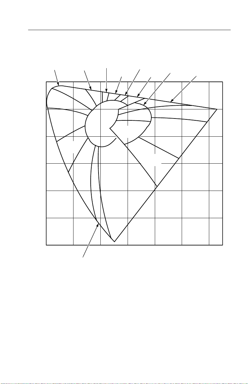
Figure B–3 shows selected isotemperature lines in the x,y coordinate
system. A light source along one of the isotemperature lines will
most nearly match the color temperature of a blackbody radiator
indicated for that line.
0.500
0.450
5500
6000
0.400
10000
0.350
15000
Y Coordinate
20000
0.300
0.250
0.200
0.200 0.250 0.300 0.350 0.400 0.450 0.500 0.550 0.600
6500
7500
8
4000
5000
X Coordinate
Figure B–3: Correlated Color T emperature Diagram
3000
2854
2500
Planckian Locus
2000
J18 Photometer Instruction Manual
B–5
Page 96

Appendix B: Chromaticity Reference
The 1976 CIE-UCS Chromaticity Diagram
The 1976 CIE-UCS (Uniform Chromaticity Scale) diagram, shown
in Figure B–4, can be used to categorize chromaticity measurements
expressed as ui, vi values. ui and vi are related to the x and y values
of the 1931 CIE chromaticity diagram by the following equations:
uȀ+
* 2x ) 12y ) 3
This diagram is similar to the 1931 CIE chromaticity diagram except
for the following:
H Equal distances on the diagram represent approximately equal
perceived color differences.
H The equal energy point is ui = 0.210, vi = 0.473.
4x
vȀ+
* 2x ) 12y ) 3
9y
B–6
J18 Photometer Instruction Manual
Page 97
Appendix B: Chromaticity Reference
Y ellowish
Green
.600
Green
.500
Green
.400
.300
vi Coordinate
.200
.100
Bluish
Greenish
Blue
Y ellow
Green
Blue
Greenish
Yellow
White
Yellow
Purple
Purplish
Pink
Orange
Y ellow
Pink
Reddish
Orange
Purple
Y ellowish
Pink
Red
Purplish
Red
Reddish
Orange
.000
.100 .200 .300 .400 .500 .600
Purplish Blue
ui Coordinate
Figure B–4: 1976 CIE-UCS Chromaticity Diagram
J18 Photometer Instruction Manual
B–7
Page 98

Appendix B: Chromaticity Reference
Spectral Tristimulus Values
Figure B–5 shows the spectral tristimulus (XYZ) values for a light
source of equal spectral power. Table B–1 lists the same data in
tabular format.
2.0
1.8
1.6
1.4
1.2
1.0
0.8
0.6
0.4
0.2
0
380 430 480 530 580 630 680 730 780
(l)
z
x(l)
(l)
y
Wavelength (nm)
Figure B–5: Spectral Tristimulus Values for Equal Spectral Power Source (CIE
1931 Standard 2° Observer)
Note that y(l) is also the photopic curve that represents the relative
sensitivity of the average human eye.
B–8
J18 Photometer Instruction Manual
Page 99

Appendix B: Chromaticity Reference
Table B–1: Spectral Tristimulus Values for Equal Spectral Power Source
(CIE 1931 Standard 2° Observer)
Wavelength (nm)
380 0.0014 0.0000 0.0065
385 0.0022 0.0001 0.0105
390 0.0042 0.0001 0.0201
395 0.0076 0.0002 0.0362
400 0.0143 0.0004 0.0679
405
410 0.0435 0.0012 0.2074
415 0.0776 0.0022 0.3713
420 0.1344 0.0040 0.6456
425 0.2148 0.0073 1.0391
430
435 0.3285 0.0168 1.6230
440 0.3483 0.0230 1.7471
445 0.3481 0.0298 1.7826
450 0.3362 0.0380 1.7721
455
460 0.2908 0.0600 1.6692
465 0.2511 0.0739 1.5281
470 0.1954 0.0910 1.2876
475 0.1421 0.1126 1.0419
x(l) y(l) z(l)
0.0232 0.0006 0.1102
0.2839 0.0116 1.3856
0.3187 0.0480 1.7441
480
485 0.0580 0.1693 0.6162
490 0.0320 0.2080 0.4652
495 0.0147 0.2586 0.3533
500
0.0956 0.1390 0.8130
0.0049 0.3230 0.2720
J18 Photometer Instruction Manual
B–9
Page 100

Appendix B: Chromaticity Reference
Table B–1: Spectral Tristimulus Values for Equal Spectral Power Source
(CIE 1931 Standard 2° Observer) (Cont.)
Wavelength (nm) z
505 0.0024 0.4073 0.2123
510 0.0093 0.5030 0.1582
515 0.0291 0.6082 0.1117
520 0.0633 0.7100 0.0782
525 0.1096 0.7932 0.0573
530
535 0.2257 0.9149 0.0298
540 0.2904 0.9540 0.0203
545 0.3597 0.9803 0.0134
550 0.4334 0.9950 0.0087
555
560 0.5945 0.9950 0.0039
565 0.6784 0.9786 0.0027
570 0.7621 0.9520 0.0021
575 0.8425 0.9154 0.0018
580
585 0.9786 0.8163 0.0014
590 1.0263 0.7570 0.0011
595 1.0567 0.6949 0.0010
600 1.0622 0.6310 0.0008
0.1655 0.8620 0.0422
0.5121 1.0000 0.0057
0.9163 0.8700 0.0017
(l)y(l)x(l)
B–10
605
610 1.0026 0.5030 0.0003
615 0.9384 0.4412 0.0002
620 0.8544 0.3810 0.0002
625
1.0456 0.5668 0.0006
0.7514 0.3210 0.0001
J18 Photometer Instruction Manual
 Loading...