

Tektronix IsoVu TIVM Series, IsoVu TIVM05, IsoVu TIVM05L, IsoVu TIVM1, IsoVu TIVM02 User Manual
...Page 1

TIVM Series
xx
ZZZ
IsoVu™ Measurement System
User Manual
*P071349500*
071-3495-00
Page 2

Page 3

xx
TIVM Series
ZZZ
IsoVu™ Measurement System
User Manual
Register now!
Click the following link to protect your product.
► www.tek.com/register
www.tek.com
071-3495-00
Page 4

Copyright © Tektronix. All rights reserved. Licensed software products are owned by Tektronix or its subsidiaries
or suppliers, and are protected by national copyright laws and international treaty provisions.
Tektronix products are covered by U.S. and foreign patents, issued and pending. Information in this publication
supersedes that in all previously published material. Specifications and price change privileges reserved.
TEKTRONIX and TEK are registered trademarks of Tektronix, Inc.
ISOVU is a trademark of Tektronix Inc.
TEKVPI is a registered trademark of Tektronix, Inc.
Contacting Tektronix
Tektronix, Inc.
14150 SW Karl Braun Drive
P.O. B o x 5 0 0
Beaverton, OR 97077
USA
For product information, sales, service, and technical support:
In North America, call 1-800-833-9200.
Worldwide, visit www.tek.com to find contacts in your area.
Page 5

Warranty
Tektronix warrants that this product will be free from defects in materials and workmanship for a period of one (1)
year from the date of shipment. If any such product proves defective during this warranty period, Tektronix, at its
option, either will repair the defective product without charge for parts and labor, or will provide a replacement
in exchange for the defective product. Parts, modules and replacement products used by Tektronix for warranty
work may be n
the property of Tektronix.
ew or reconditioned to like new performance. All replaced parts, modules and products become
In order to o
the warranty period and make suitable arrangements for the performance of service. Customer shall be responsible
for packaging and shipping the defective product to the service center designated by Tektronix, with shipping
charges prepaid. Tektronix shall pay for the return of the product to Customer if the shipment is to a location within
the country in which the Tektronix service center is located. Customer shall be responsible for paying all shipping
charges, duties, taxes, and any other charges for products returned to any other locations.
This warranty shall not apply to any defect, failure or damage caused by improper use or improper or inadequate
maintenance and care. Tektronix shall not be obligated to furnish service under this warranty a) to repair damage
result
b) to repair damage resulting from improper use or connection to incompatible equipment; c) to repair any damage
or malfunction caused by the use of non-Tektronix supplies; or d) to service a product that has b een modified or
integrated with other products when the effect of such modification or integration increases the time or difficulty
of servicing the product.
THIS WARRANTY IS GIVEN BY TEKTRONIX WITH RESPECT TO THE PRODUCT IN LIEU OF A NY
OTHER WARRANTIES, EXPRESS OR IMPLIED. TEKTRONIX AND ITS VENDORS DISCLAIM ANY
IMPLIED WARRANTIES OF MERCHANTABILITY OR FITNESS FOR A PARTICULAR PURPOSE.
TRONIX' RESPONSIBILITY TO REPAIR OR REPLACE DEFECTIVE PRODUCTS IS THE SOLE
TEK
AND EXCLUSIVE REMEDY PR OVIDED TO THE CUSTOMER FOR BREACH OF THIS WARRANTY.
TEKTRONIX AND ITS VENDORS WILL NOT BE LIABLE FOR ANY INDIRECT, SPECIAL, INCIDENTAL,
OR CONSEQUENTIAL DAMAGES IRRESPECTIVE OF WHETHER TEKTRONIX OR THE VENDOR HAS
ADVANCE NOTICE OF THE POSSIBILITY OF SUCH DAMAGES.
[W2 – 15AUG04]
btain service under this warranty, Customer must notify Tektronix of the defect before the expiration of
ing from attempts by personnel other than Tektronix representatives to install, repair or service the product;
Page 6

Page 7

Table of Contents
Important safety information ............. ................................ ................................ ......... v
General safety summary ...................................................................................... v
Service safety summary ............................ ................................ ......................... vii
Terms in this manual ..................... .................................. ................................ . viii
Symbols and terms on the product......................................................................... viii
Preface .............................................................................................................. ix
Key features ........................... .................................. ................................ ...... ix
Laser certification................. .................................. ................................ .......... ix
Product description ......................... ................................ ................................ ... x
Models ......................................................................................................... xi
Supported oscilloscopes...................................................................................... xi
Operating information..... ................................ .................................. ....................... 1
Accessories..................................................................................................... 1
Operating considerations...................................................................................... 2
Controls and indicators............................... .................................. ....................... 7
Connecting to a circuit . ................................ .................................. .................... 10
Self calibration ................................................................................................ 12
AutoZero....................................................................................................... 14
Menu button................. ................................ ................................ .................. 14
Offset correction .............................................................................................. 15
1X/2X Range ............................ .................................. ................................ .... 17
Auto Range.................................................................................................... 18
Selecting a sensor tip cable .................................................................................. 19
Output clamping ............ ................................ .................................. ................ 20
Sensor tip loading............................................................................................. 20
Probe compensation .......................................................................................... 21
Deskew......................................................................................................... 21
Input offset ........ ................................ .................................. .......................... 21
Application examples ................... ................................ ................................ .......... 23
Example 1: High-side V
Example 2: High-side drain current measurement .............................. .......................... 25
Example 3: ESD troubleshooting ................................. ................................ .......... 26
Reference information ............................................................................................ 29
Specifications.. ................................ ................................ ................................ 29
Dimensional drawings........................................................................................ 33
IsoVu measurement system block diagram ...... ................................ .......................... 36
Tripods........... ................................ ................................ .............................. 37
Installing the probe tip adapters . .... . ..... . ..... . ..... . ..... . ... . . ..... . ..... . ..... . ..... . ... . . . .... . ..... . . 39
Installing the square pins on the circuit board . ..... . .... . . .... . ..... . ..... . ..... . .... . ..... . ..... . ..... . .. 42
measurement................................................................... 23
GS
TIVM Series Measurement System User Manual i
Page 8

Table of Contents
User service .......... .................................. ................................ ............................ 45
Service offerings.......... ................................ .................................. .................. 45
Preventive maintenance.................... ................................ ................................ .. 45
Performance verification procedures ....................................................................... 46
Propagation delay............................................................................................. 47
Troubleshooting and error conditions ...................... ................................ ................ 50
Repack the m
Test record ..................................................................................................... 53
Appendix A: Remote programming ............................................................................. 55
CH<n>:PRObe?............................................................................................... 55
CH<n>:PRObe:AUTOZero EXECute ..................................................................... 55
CH<n>:PRObe:COMMAND “CLAMP”, {“ON” | “OFF”} ............................. ................ 55
CH<n>:P
CH<n>:PRObe:FORCEDRange <NR3> .................................................................. 56
CH<n>:PRObe:GAIN? .... ................................ .................................. ................ 56
CH<n>:PRObe:ID {:SERnumber | :TYPe}? ...... ................................ ........................ 56
CH<n>:PRObe:PROPDELay?............ .................................. ................................ 57
CH<n>:PRObe:RECDESkew?.............................................................................. 57
CH<n
CH<n>:PRObe:UNIts?............................. ................................ .......................... 57
CH<n>:PROBECOntrol {AUTO | MAN}................................................................. 57
CH<n>:PROBEFunc:EXTAtten <NR3>................................................................... 57
CH<n>:PROBEFunc:EXTDBatten? ....................................................................... 57
CH<n>:PROBEFunc:EXTUnits {“UU” | “None”}..... .................................. ................ 58
pendix B: Compliance information .......................................................................... 59
Ap
Safety compliance ............................................................................................ 59
Environmental considerations............................................................................... 61
Index
easurement system for shipment ............................................................ 52
RObe:SET {“CLAMP ON” | “CLAMP OFF”}................................................ 55
>:PRObe:RESistance? ................................................................................ 57
ii TIVM Series Measurement System User Manual
Page 9

List of Figures
Figure i: TIVM Series IsoVu Measurement System............................................................ x
Figure 1: Maximum safe handling limits for common mode voltages between the sensor head and earth
ground........................................................................................................... 5
Figure 2: RF burn hazard zone around the sensor head ....................... ................................. 6
Figure 3: Controller indicators and buttons...................................................................... 7
Figure 4: Labels on the sensor head.............................................................................. 9
Figure 5: Sensor tip cable top and botto
Figure 6: Connect the Comp box to the oscilloscope.. . . ..... . ..... . .... . ..... . ..... . .... . ..... . ... . . . .... . ... 11
Figure 7: Connecting the sensor tip cable to the sensor head................................................. 11
Figure 8: Connect the s ensor head to the flexible tripod ........ ................................ .............. 12
Figure 9: Probe Setup menu...................................................................................... 14
Figure 10: Digital filter aliasing ................................................................................. 15
Figure 11: Digital filter aberrations (about 2.5% of V
Figure 12: Digital filter aberrations after disabling offset correction........................................ 17
Figure 13: Top sensor tip labels.................................... ................................ .............. 17
Figure 14: Bottom sensor tip labels ............................................................................. 20
Figure 15: Half-bridge circuit showing the gate, source, and drain of the high-side FET.. . .... . ..... . ... 23
Figure 16: High-side turn-on characteristics ....... .................................. .......................... 24
Figure 17: High side current shunt .............................................................................. 25
Figure 18: SMT resistor model .................................................................................. 26
Figure 19: ESD discharge test example. .................................. ................................ ...... 27
Figure 20: Sensor head dimensions with probe tip cover ................... ................................ .. 33
Figure 21: Sensor head dimensions without probe tip cover ................... .............................. 34
Figure 22: Controller dimensions................................................................................ 34
Figure 23: Comp box dimensions ............................................................................... 35
Figure 24: Probe tip adapter dimensions............................ ................................ ............ 35
Figure 25: Block diagram .............. .................................. ................................ ........ 36
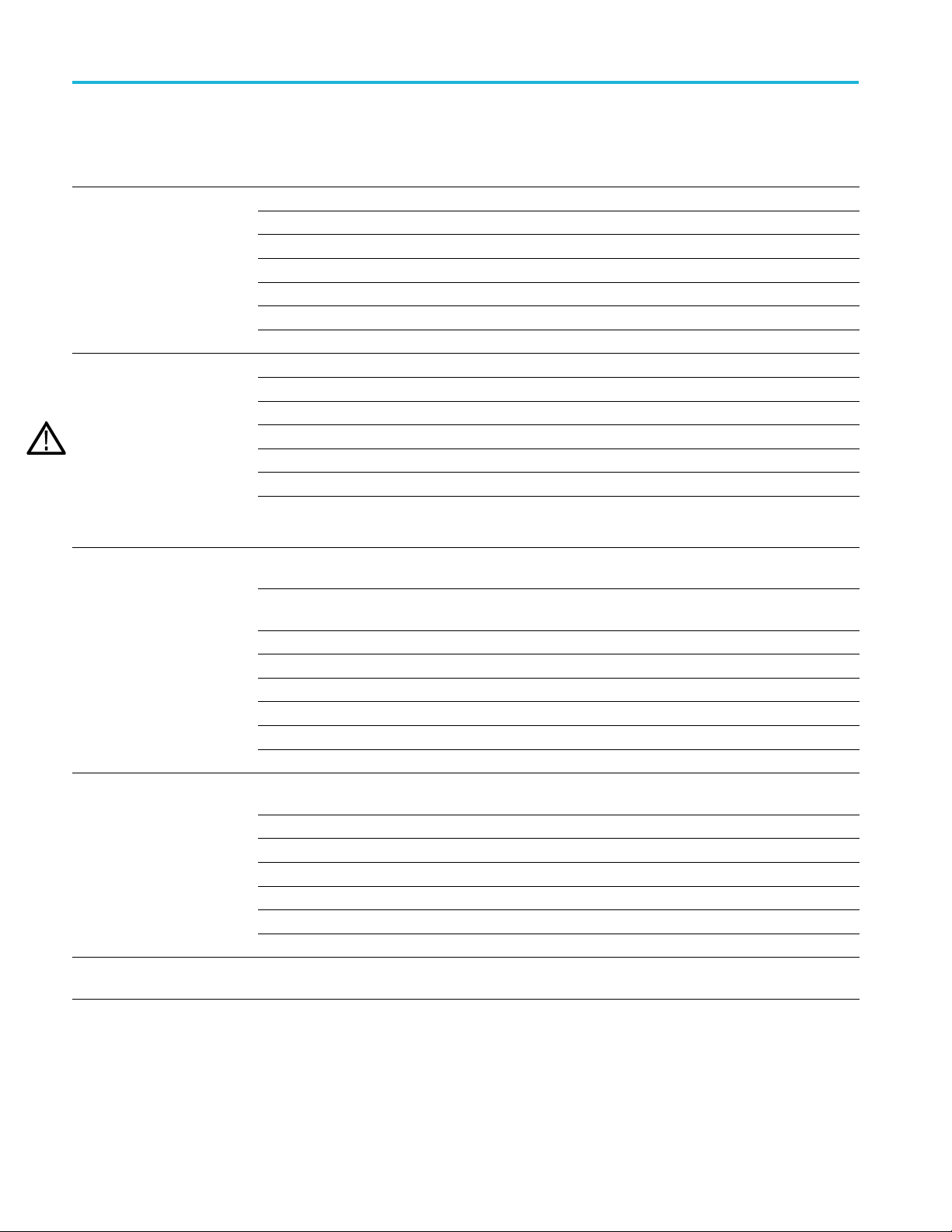
Figure 26: Installing the flexible tripod under the DUT. ...................................................... 37
Figure 27: Connecting the sensor head to the top of the DUT with the flexible tripod. ................... 37
Figure 28: Connecting to an adapter on the circuit board with the probe tip tripod ....................... 38
Figure 29: Lining up the MMCX-to-0.1-inch (2.54 mm) adapter on the circuit board.................... 39
Figure 30: Lining up the MMCX-to-0.062-inch (1.57 mm) adapter on the circuit board .... . ..... . .... . . 40
Figure 31: Pushing the MMCX-to-0.062-inch (1.57 mm) adapter in place................................. 40
Figure 32: Pushing the MMCX-to-0.1-inch (2.54 mm) adapter in place............................ ........ 41
Figure 33: Adapter clearance requirements ...................... .................................. ............ 42
Figure 34: Removing the header from square pins on the circuit board..................................... 43
Figure 35: Using the soldering aide to install the square pins on the circuit board ........................ 44
Figure 36: Propagation delay measurement .................................................................... 50
m labels ............................................................... 9
) ... ................................ .................. 16
p-p
TIVM Series Measurement System User Manual iii
Page 10

Table of Contents
List of Tables
Table 1: Standard accessories ........ .................................. ................................ ........... 1
Table 2: Opt
Table 3: Input specifications.................................... ................................ ................... 3
Table 4: Environmental considerations .......................................................................... 3
Table 5: Controller indicators and buttons.................................... .................................. . 7
Table 6: Sensor tip selection table ............................................................................... 19
Table 7: Input offset............................................................................................... 21
Table 8: W
Table 9: Electrica l specifications .......... ................................ .................................. .... 29
Table 10: Physical specifications .......... ................................ ................................ ...... 33
Table 11: Required equipment for performance verification ................................................. 46
Table 12: Problems and possible solutions ..................................................................... 50
Table 13: Test record................................ ................................ .............................. 53
Table
ional accessories ..................................................................................... 2
arranted specifications.................................. ................................ .............. 29
14: Sensor tip cables and dynamic ranges........................... .................................. .. 56
iv TIVM Series Me asurement System User Manual
Page 11

Important safety information
This manual contains information and warnings that must be followed by the user
for safe operation and to keep the product in a safe condition.
To safely perform service on this product, additional information is provided at
the end of this section. (See page vii, Service safety summary.)
General safety summary
Use the product only as specified. Review the following safety precautions to
avoid injury and prevent damage to this product or any products connected to it.
Carefully read all instructions. Retain these instructions for future reference.
Comply with local and national safety codes.
For correct and safe operation of the product, it is essential that you follow
generally accepted safety procedures in addition to the safety precautions specified
in this manual.
The product is designed to be used by trained personnel only.
To avoid fire or personal
injury
Only qualified perso
the cover for repair, maintenance, or adjustment.
Before use, always check the product with a known source to be sure it is
operating correctly.
This product is not intended for detection of hazardous voltages.
Use personal protective equipment to prevent shock and arc blast injury where
hazardous live conductors are exposed.
While using this product, you may need to access other parts of a larger system.
Read the safety sections of the other component manuals for warnings and
cautions related to operating the system.
When incorporating this equipment into a system, the safety of that system is the
responsibility of the assembler of the system.
Connect and disconnect properly. Do not connect or disconnect sensor tip cables,
test leads, or accessories while they are connected to a voltage source. Use only
test leads and accessorie
to be suitable for the product.
Observe all terminal ratings. To avoid fire or shock hazard, observe all ratings
and markings on the product. Consult the product manual for further ratings
information before making connections to the product. Do not exceed the
Measurement Category (CAT) rating and voltage or current rating of the lowest
rated individual component of a product or accessory.
nnel who are aware of the hazards involved should remove
s supplied w ith the product, or indicated by Tektronix
TIVM Series Measurement System User Manual v
Page 12

Important safety information
Do not apply a po
Do not operate without covers. Do not operate this product with covers or panels
removed, or with the case open. Hazardous voltage exposure is possible.
Avoid exposed circuitry. Do not touch exposed connections and components
when power is present.
Do not operate with suspected failures. If you suspect that there is damage to this
product, have it inspected by qualified service personnel.
Disable the product if it is damaged. Do not use the product if it is damaged
or operates incorrectly. If in doubt about safety of the product, turn it off and
disconnect the power cord. Clearly mark the product to prevent its further
operation.
Before use, inspect accessories for mechanical damage and replace when
damaged. Do not use them if they are damaged, or if there is exposed metal.
Examine the exterior of the product before you use it. Look for cracks or missing
pieces.
Use only specified replacement parts.
Do not operate in wet/damp conditions. Be aware that condensation may occur if
a unit is moved from a cold to a warm environment.
tential that exceeds the m aximum rating.
Sensor tip cables
Do not operate in an explosive atmosphere.
Keep product surfaces clean and dry. Remove the input signals before you clean
the product.
Provide a safe working environment. Always place the product in a location
convenient for viewing the display and indicators.
Be sure your work area meets applicable ergonomic standards. Consult with an
ergonomics professional to avoid stress injuries.
Maintain safe clearance from the sensor head and sensor tip cable while connected
to the energized circuit as recommended in this manual.
Remove the sensor tip cable and adapters from the test circuit when not in use.
Leave the sensor tip cable connected to the sensor head when not in use.
Use only correct Measurement Category (CAT), voltage, temperature, altitude,
and amperage rated sensor tip cables and accessories for any measurement.
Beware of high voltages. Understand the voltage ratings for the product you are
using and do not exceed those ratings. It is important to know and understand the
maximum measurement voltage rating of the product. The voltage rating depends
vi TIVM Series Measurement System User Manual
Page 13
Important safety information
on the instrume
manual for more information.
WAR NI NG . To prevent electrical shock, do not exceed the maximum measurement
or maximum voltage category.
Connect and disconnect properly.
CAUTION. To avoid damage to the equipment, de-energize the test circuit before
connecting or disconnecting the sensor tip cable.
Servicesafetysummary
The Serv
safely perform service on the p roduct. Only qualified personnel should perform
service procedures. Read this Service safety summary and the General safety
summary before performing any service procedures.
To avoid electric shock. Do not touch exposed connections.
nt and your application. Refer to the Specifications section of the
icesafetysummarysection contains additional information required to
Do not service alone. Do not perform internal service or adjustments of this
product unless another person capable of rendering first aid and resuscitation is
present.
Disconnect power. To avoid electric shock, switch off the product power and
connect the power cord from the mains power before removing any covers or
dis
panels, or opening the case for servicing.
Use care when servicing with power on. Dangerous voltages or currents may exist
in this product. Disconnect power, remove battery (if applicable), and disconnect
test leads before removing protective panels, soldering, or replacing components.
Verify safety after repair. Always recheck ground continuity and mains dielectric
strength after performing a repair.
TIVM Series Measurement System User Manual vii
Page 14

Important safety information
Termsinthismanual
These terms may appear in this manual:
WARNING. Warning statements identify conditions or practices that could result
in injury or loss of life.
CAUTION. Caution statements identify conditions or practices that could result in
damage to this product or other property.
Isolated, electrically floating. The terms isolated, electrically floating,and
galvanically isolated are used in this document to indicate a measurement where
there is no direct conduction path to earth ground.
Symbols and terms on the product
These terms may appear on the product:
DANGER indicates an injury hazard immediately accessible as you read
the marking.
WARNING indicates an injury hazard not immediately accessible as you
read the marking.
CAUTION indicates a hazard to property including the product.
this symbol is marked on the product, be sure to consult the manual
When
to find out the nature of the potential hazards and any actions which have to
betakentoavoidthem. (Thissymbolmayalsobeusedtorefertheuserto
ings in the manual.)
rat
The following symbol(s) may appear on the product:
viii TIVM Series Measurement System User Manual
Page 15
Preface
Preface
Key features
Laser certification
This documen
Series IsoVu Mea surement System. The measurement system offers a galvanically
isolated measurement solution for accurately resolving high bandwidth, low
voltage differential signals up to ±50 Vpk in the presence of large common
mode voltages with the best in class common mode rejection p erformance across
its bandwidth.
New IsoVu technology - galvanically isolated, floating, measurement system
Differential voltages up to ±50 Vpk (depending on sensor tip)
Large common mode voltage range up to 2 kV
t provides information for installing and using the Tektronix TIVM
Bandwidth from DC to 1 GHz
> 120 dB (1 million to 1 common mode rejection ratio) from DC to
100 MHz and 80 dB (10,000 to 1) at 1 GHz
This product complies with 21 CFR 1040.10 and 1040.11 except for deviations
suant to Laser Notice No. 50, dated June 24, 2007.
pur
CAUTION. Useofcontrolsoradjustmentsforperformanceofproceduresother
than those specified herein may result in hazardous radiation exposure.
TIVM Series Measurement System User Manual ix
Page 16

Preface
Product description
The Tektronix TIVM Series IsoVu Measurement System offers a completely
galvanically isolated (optical isolation) system. The system consists of a sensor
tip cable, a sensor head, a controller, and a TekVPI interface as shown in the
following figure. Hazardous voltages in the sensor head are completely isolated
from the con
troller and oscilloscope by optical fiber cables.
Figure i: TIVM Series IsoVu Measurement System
Comp box
Controller
x TIVM Series Measurement System User Manual
The TekVPI compensation box (Comp box) connects the measurement system
to one of the input channels on the oscilloscope. Power is supplied to the
asurement system through the TekVPI interface of the oscilloscope.
me
The controller connects to the oscilloscope through a coaxial cable and the Comp
box. Buttons and indicators on the controller provide a means for controlling the
easurement system and indicating the overall status.
m
Page 17

Preface
Models
Sensor head
Sensor tip cables
The sensor head
the controller. It contains an electro-optic converter that converts the electrical
signal from the sensor tip cables to an optical signal sent to the controller.
Different se
the DUT. The sensor tip cable consists of an SMA connector that connects to the
sensor head; two screws to secure the sensor tip cable to the sensor head; the other
end of the sensor tip cable connects to the DUT through an MMCX connector
and optional adapters.
The TIVM Series IsoVu Measurement System includes the following models:
TIVM1. Tektronix IsoVu 1 GHz Medium Voltage with 3 m cable
TIVM1L. Tektronix IsoVu 1 GHz Medium Voltage with 10 m cable
TIVM05. Tektronix IsoVu 500 MHz Medium Voltage with 3 m cable
TIVM05
TIVM02. Tektronix IsoVu 200 MHz Medium Voltage with 3 m cable
provides an interface between the device-under-test (DUT) and
nsor tip cables are available to connect the measurement system to
L. Tektronix IsoVu 500 MHz Medium Voltage with 10 m cable
Supp
orted oscilloscopes
The measurement system can be used with the following Tektronix oscilloscopes.
For oscilloscopes not included in this list, contact your local Tektronix
rep
In addition to the above oscilloscopes, the measurement system can also be used
with the following oscilloscopes with a TCA-VPI50 adapter.
TIVM02L. Tektronix IsoVu 200 MHz Medium Voltage with 10 m cable
resentative.
MDO3000 series
MSO/DPO4000B serie s
MDO4000B/C series
MSO/DPO5000B serie s
DPO7000C series
MSO/DPO70000C series
MSO/DPO70000DX series
DPO70000SX series
TIVM Series Measurement System User Manual xi
Page 18

Preface
xii TIVM Series Measurement System User Manual
Page 19

Operating information
Accessories
This section lists the standard and optional accessories available for the
measurement s ystem.
Standard ac
cessories
Table 1: Standard accessories
Tektronix
Accessory
IsoVu product carrying case, soft case
IsoVu accessories carrying case, soft case
Solder aid for 0.062-inch (1.57 mm) pitch square pins (0.016 - 0.018-inch
(0.4 - 0.46 mm) square pin installation tool)
5X Sensor tip cable
25X Sensor tip cable
5/16-inch SMA wrench/driver tool
Probe tip adapter (blue), MMCX to 0.1-inch (2.54 mm) square pin
(0.025-inch (0.635 mm) square pins)
Probe tip adapter (white), MMCX to 0.062-inch (1.57 mm) square pin (0.016
- 0 .018-inch (0.4 - 0.46 mm) square pins)
DUT Interface pin kit with (qty. 20) 0.018-inch (0.46 mm) round solder-in
pins
Flexible tripod with quick release 352-1171-xx
Flexible tripod feet, 3 each
Probe tip tripod support with living h inge, 2 each 352-1170-xx
Certificate of traceable calibration
Data calibration report
part number
016-2108-xx
016-2110-xx
003-1946-xx
IVTIP5X
IVTIP25X
003-1947-xx
131-9717-xx
131-9677-xx
020-3169-xx
344-0693-xx
—
—
TIVM Series Measurement System User Manual 1
Page 20

Operating information
Optional accessories
Additional acc
following table lists the optional accessories.
Table 2: Optional accessories
Accessory
1X Sensor tip cable
10X Sensor tip cable
50X Sensor tip cable
Operating considerations
Read this
operating requirements and clearance requirements including possible hazardous
areas when the measurement system is connected to the DUT.
Measurement system
handling best practices
The mea
to avoid damage or degrading the performance due to mishandling. Consider the
following precautions when handling the fiber-optic cables and sensor tip cables:
essories, such as other sensor tip cables are available. The
Tektronix
part number
IVTIP1X
IVTIP10X
IVTIP50X
section before i nstalling your measurement system to be aware of the
surement system consists of quality parts and should be tre ated with care
Do not crush, crimp, or sharply bend the fiber-optic cable. Avoid making
loops in the fiber-optic cable smaller than 5 inches (12.7 cm).
Do not twist the fiber-optic cable; twisting the cable will stress the optical
fibers.
Do not allow kinks or knots to develop in the fiber-optic cable.
id putting tension on the fiber-optic cable.
Avo
Do not pull or jerk the fiber-optic cable, especially when kinks or knots are
esent.
pr
Do not drop the sensor head or controller assembly since damage and
isalignment of the internal optical components can result.
m
Avoid over-bending the sensor tip cables; do not exceed the minimum bend
radius of 2.0 inches (5.1 cm).
Avoid crushing the cables by accidentally running over the cable with a chair
wheel or by dropping a heavy object onto the cable.
Never support the weight of the sensor head or controller by the fiber-optic
cable.
Store the measurement system in the supplied carrying case when not in use.
2 TIVM Series Measurement System User Manual
Page 21

Operating information
Environmental
requirements
The following t
ables describe specifications and maximum operating
environmental ratings for the measurement system when connected to a DUT
and a Tektronix oscilloscope.
Table 3: Input specifications
Feature Description
1000 V
2000 V peak, CAT I (expected transient voltage 2500 V peak)
Differential mode Sensor tip cable dependent (See the Sensor tip cable voltage
rating below.)
rms
,CATIICommon mode
Table 4: Environmental considerations
Feature Description
Temperat
Hu
ure
ler
Control
ing
Operat
Non-operating
r head
Senso
ting
Opera
Non-operating
sor tip cables/adapters
Sen
rating and
Ope
non-operating
midity
ntroller
Co
perating
O
on operating
N
Sensor head
Operating 5% to 80% RH (Relative Humidity), at up to 40 °C (104 °F)
Non operating
0°Cto4
-40 °C t
0°Cto
-40 °
-40
5
non-condensing
5% to 85% RH (Relative Humidity), at up to 40 °C (104 °F)
5% to 45 % RH above 40 °C (104 °F) up to 70 °C (158 °F),
non-condensing
5% to 45 % RH above 40 °C (104 °F) up to 70 °C (158 °F),
non-condensing
5% to 85% RH (Relative Humidity), at up to 40 °C (104 °F)
5% to 45 % RH above 40 °C (104 °F) up to 70 °C (158 °F),
non-condensing
0 ° C (32 °F to 104 °F)
o70°C(-40°Fto158°F)
70 °C (32 °F to 158 °F)
Cto70°C(-40°Fto158°F)
°C to 85 °C (-40 °F to 185 °F)
% to 85% RH (Relative H umidity), at up to 40 °C (104 °F),
TIVM Series Measurement System User Manual 3
Page 22

Operating information
Table 4: Environmental considerations (cont.)
Feature Description
Sensor tip cables/adapters
Operating 5% to 80% RH (Relative Humidity), at up to 40 ° C (104 °F)
5% to 45 % RH above 40 °C (104 °F) up to 85°C (185 °F),
non-condensing
Non operating
Altitude
Operating 3000 m (9843 ft.)
Non operating
5% to 85% RH (Relative Humidity), at up to 40 °C (104 °F)
5% to 45 % RH above 40 °C (104 °F) up to 70 °C (158 °F),
non-condensing
12,000 m (39370 ft.)
Cleara
nce requirements
The unique common mode voltage range of the measurement system allows it to
be used in the presence of high frequency/high voltage common mode signals. It
is important to observe all precautions while using this product.
ING. RF burns can occur while using this measurement system. Anyone
WARN
making measurements that might come within the RF burn regions indicated in
the following figure should be familiar with the hazards of working with signals in
these regions and take appropriate action, such as RF shielding for the DUT.
4 TIVM Series Measurement System User Manual
Page 23
Operating information
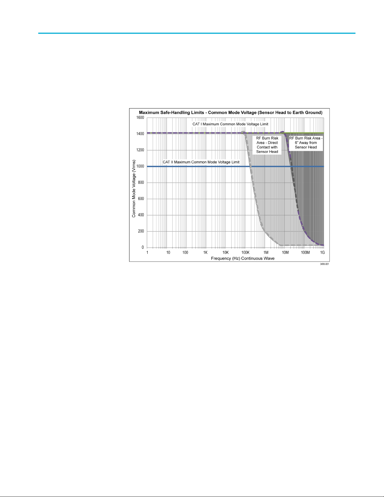
While measurin
RF burns. Refer to the following derating curve to identify the danger areas.
Measuring common mode signals within the light gray area can result in RF burns
while directly contacting the sensor head. Measuring common mode signals
within the dark gray shaded area can result in RF burns when within 6 inches
(15.25 cm) of the sensor head.
g high frequency common mode signals, there is a risk of
Figure 1: Maximum safe handling limits for common mode voltages between the
sensor head and earth ground.
TIVM Series Measurement System User Manual 5
Page 24

Operating information
The following fi
potential RF burn area when working with hazardous voltages.
gure shows the components of the measurement system and the
Figure 2: RF burn hazard zone around the sensor head
6 TIVM Series Measurement System User Manual
Page 25

Operating information
Controls and i
Controller
ndicators
The following figure shows the indicators and buttons on the controller; their
functions are described in the following table.
Figure 3: Controller indicators and buttons
Table 5: Controller indicators and buttons
Item Description
1
2
3
OVER RANGE Indicator. This red LED indicates if the DC/low frequency
differential voltage applied to the sensor head or attached sensor tip cable
has exceeded the maximum speci fied input voltage levels.
RANGE indicator. The two LEDs indicate the differential input range
setting.
RANGE button. Push this button to toggle between one of two differential
input voltage ranges.
MENU button. Push this button to view the Probe Control menu on the
oscilloscope display.
TIVM Series Measurement System User Manual 7
Page 26

Operating information
Table 5: C ontroller indicators and buttons (cont.)
Item Description
4
5
6
CLAMPING indicator. This LED indicates whether the output clamping
is enabled.
CLAMPING button. Push this button to enable or disable the output
clamping feature.
SELF CAL indicator. This LED indicates the self calibration status.
Solid green. The self calibration has passed.
Flashing orange. The self calibration is in progress.
Solid red. The self calibration has failed.
Solid Orange. The self calibration has not been run or is questionable.
SELF CAL button. Push this button to start the self calibration routine.
STATUS indicator. This LED indicates the status of the measurement
system:
Solid green. The unit has powered on and passed the power-on self
tests and is in normal operation.
Flashing green. The unit has not completed the power-up sequence.
This is typically due to a communication fault between the host
oscilloscope and the IsoVu unit. Disconnect the TekVPI comp box
and then reattach the comp box.
Solid or flashing red. Error condition that requires the unit to be sent to
Tektronix for service.
Flashing red/yellow. The unit has failed the power on self tests.
Cycle the power; if the problem persists, the unit needs to be sent to
Tektronix for service.
8 TIVM Series Measurement System User Manual
Page 27
Operating information
Sensor head
Sensor tip cables
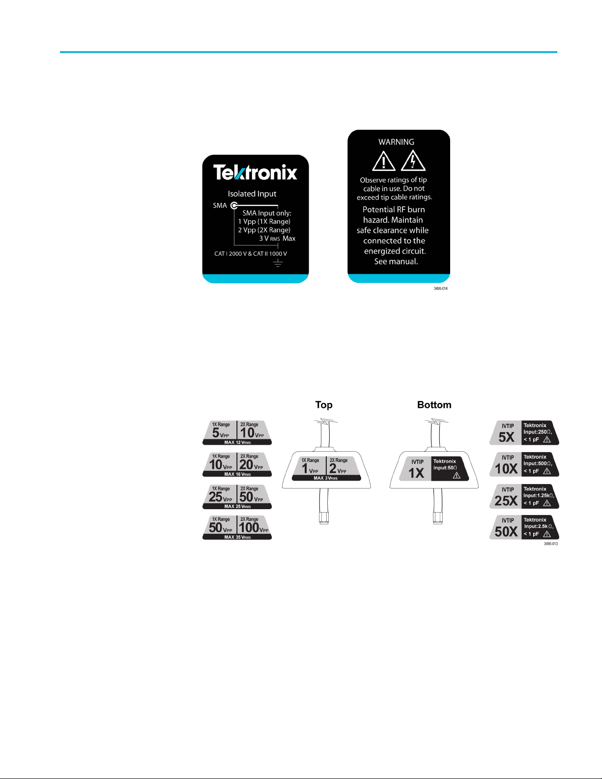
Labels on the se
the DUT. They also provide reminders of the potential RF burn hazards while
connected to the DUT.
Figure 4: Labels on the sensor head
Each sensor tip cable has a set of labels on the top and bottom. The top labels
provide reminders of the maximum differential input voltage range for each tip
cable. The bottom labels include the name of the tip cable and the differential
input resistance and capacitance for the tip cable (differential loading).
nsor head provide h igh-level specifications for connecting to
Figure 5: Sensor tip cable top and bottom labels
TIVM Series Measurement System User Manual 9
Page 28

Operating information
Connecting to
a circuit
WARNING. This measurement system contains laser sources; exposing these
laser sources may cause laser exposure. Except for the sensor tip cables on the
sensor head, do not remove any plastic or metallic covers from the sensor head
or controller or attempt to disassemble the product.
WARNING. Do not connect the measurement system to an energized circuit to
avoid the risk of shock. Always de-energize the circuit-under-test before installing
or removing the tip cable from the circuit-under-test.
WARNING. To avoid the risk of electrical shock or RF burns while the DUT
is energized, do not touch the sensor head or sensor tip cable while taking
measurements. Always keep a six (6) inch (15.25 cm) clearance from the sensor
head du
Be sure to check the maximum ratings and derating curve for more information on
the RF b
CAUTION. To avoid possible damage to the equipment, do not connect the coaxial
(com
portion of a circuit. The additional capacitance can cause circuit damage.
Connect the coaxial (common) shield to the low impedance section of the circuit.
ring the measurement. (See Figure 2 on page 6.)
urn hazard zone. (See Figure 1 on page 5.)
mon) shield of the sensor tip cable or SMA input to the high impedance
NOTE. Touching the sensor head or sensor tip cable when measuring a high
frequency, high voltage common mode signal increases the capacitive coupling
and can degrade the common mode loading on the circuit-under-test.
10 TIVM Series Measurement System User Manual
Page 29
Operating information
The following s
between a Tektronix oscilloscope and the DUT.
1. Verify the DUT
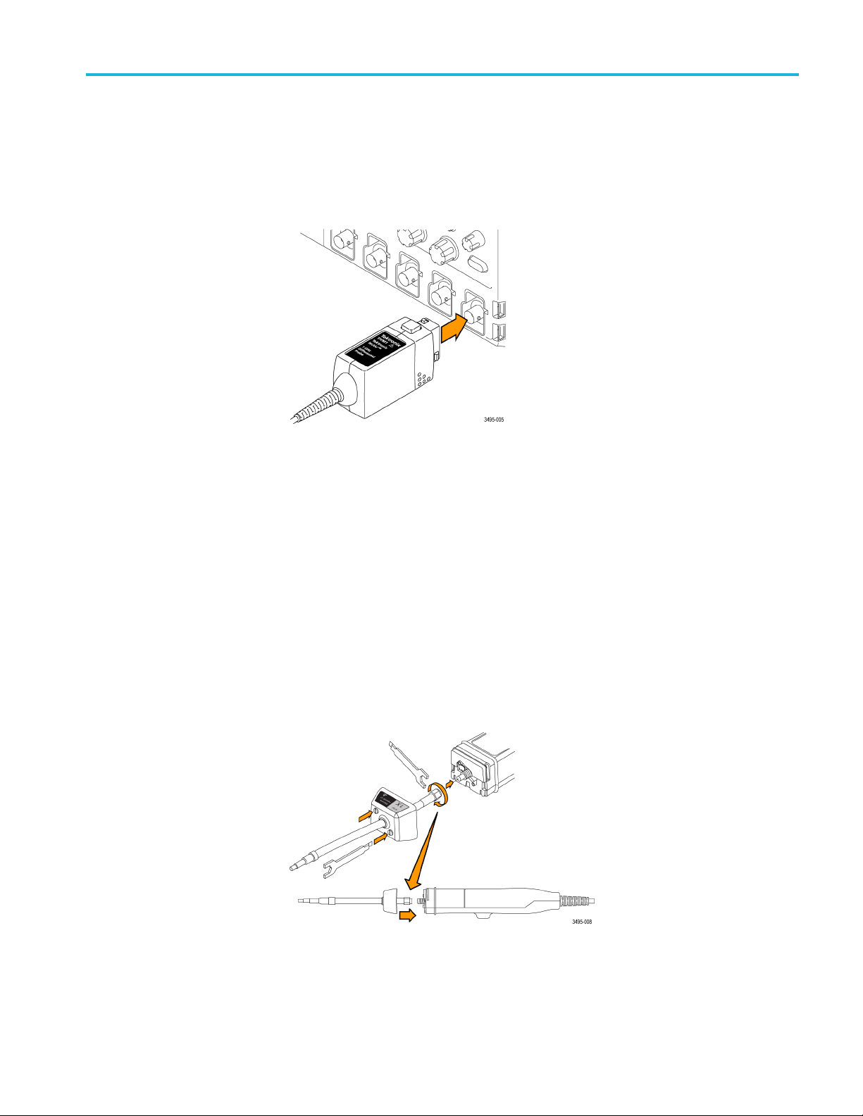
2. Connect the Comp box to one of the channels on the oscilloscope.
Figure 6: Connect the Comp box to the oscilloscope
3. Refer to the following figure and install the sensor tip cable to the sensor head.
a. Line up the sensor tip cable with the sensor head.
teps describe the process for connecting the measurement system
is not connected to an energized circuit.
Take care to avoid bending or twisting the sensor tip cable assembly
during this process.
b. Connect the SMA connector of the sensor tip cable to the sensor head.
Use the accessories wrench to tighten the SMA cable to 4 to 5-in lbs.
Use the adjustment tool that was shipped with your system.
c. Pres
s the sensor tip cable housing against the sensor head and then tighten
the two screws to 3 to 5-in lbs.
the adjustment tool that was shipped with your system.
Use
Figure 7: Connecting the sensor tip cable to the sensor head
TIVM Series Measurement System User Manual 11
Page 30

Operating information
4. Connect the sen
This support keeps the sensor head steady reducing the potential mechanical
stresses at the electrical connection point of the DUT. The support also keeps
the sensor head away from surrounding circuits and conductive objects to
minimize the parasitic capacitive coupling to these surroundings.
NOTE. Thematingthreadinthese
support, make s ure that mating thread is UNC¼-20.
Figure 8: Connect the sensor head to the flexible tripod
sor head to the flexible tripod or a similar support.
nsor head is UNC¼-20. If you use a different
Self calibration
NOTE. To obtain the most accurate m easurement, allow the measurement system
to warm up for 20 minutes. Then perform the se
the tip cable to the DUT and taking the measurement.
5. Connect the MMCX end, of the sensor tip cabl
the DUT or to a square pin adapter on the DUT. The adapters connect to
square pins with either 0.100-inch (2.54 mm) spacing or 0.062-inch (1.57 mm)
spacing. (See Figure 28 on page 38.)
6. Set up the controls on the oscilloscope.
7. Apply power to the DUT to take the measurement.
Press the SELF CAL button on the controller to adjust the operating point of the
measurement system for the current range and clamp setting. (This function is not
available in the Probe Setup menu of the oscilloscope.)
NOTE. Make sure there is no differential voltage present at the sensor tip cable
when performing the self calibration.
lf calibration before connecting
e to an MMCX connector on
12 TIVM Series Measurement System User Manual
Page 31

Operating information
Programming
When you power o
the controller is orange, indicating that the operating point of the measurement
system has not been optimized. As a result, the accuracy of the measurement
system might be degraded. The SELF CAL sequence should always be run
on the system after it is first powered on and has warmed up for 20 minutes.
After pushing the SELF CAL button, the indicator blinks orange during the self
calibratio
red when the operation fails.
There are s
status indicator turns orange to indicate when this is necessary:
Users wanting to initiate the self calibration through the programmatic interface
must configure the measurement system to perform a self calibration every time
it receives the AutoZero command. To link these functions, hold the MENU
button down and momentarily press the SELF CAL button. The OVER RANGE
indicator should blink red twice. This mode is non-volatile, and it also changes
the
Restore the original operation by repeating the MENU-SELF CAL button pushes.
In this case the OVER RANGE indicator will blink once.
n process; it turns solid green when the operation completes or solid
ituations when further self calibration is required. The SELF CAL
The measu
Changes are made to the range (1X|2X) or clamp (ON|OFF) setting.
The temperature in the sensor head changes more than 10 °C.
The internal compensation adjustments have shifted outside their normal
operating ranges.
The sensor tip cable is changed.
operation of the AutoZero button in the Probe Setup menu of the oscilloscope.
n the measurement system, the SELF CAL status indicator on
rement system is first attached to the oscilloscope.
TIVM Series Measurement System User Manual 13
Page 32

Operating information
AutoZero
Menu button
When the displayed waveform is not centered correctly (for example, due to a
small DC offset error), you might need to press the AutoZero button in the Probe
Setup menu of the oscilloscope. This might be necessary for the first time after
the self calibration operation has completed. Make sure there is no differential
signal pres
ent at the sensor tip cable.
Press the M
oscilloscope, similar to the following figure.
Figure 9: Probe Setup menu
ENU button on the controller to view the Probe Setup menu on the
Use the buttons on the oscilloscope to change the probe setups. Some of the
functions are the same as pushing the buttons on the controller, such as turning
clamping on or off, or setting the input ranges.
14 TIVM Series Measurement System User Manual
Page 33

Operating information
Offset correc
tion
The measurement system uses state-of-the-art technology that allows the DUT
to be totally isolated from the oscilloscope. This results in a very large common
mode rejecti
be obscured by the h igh common mode interference.
The TIVM Ser
any drift in the system due to changes in temperature or fiber movement. The
offset correction algorithm maintains a constant DC level for the displayed
on-screen signal.
One of the components used for offset correction is a digital low-pass filter.
Normally, the frequency of the signal is high enough that the operation of the
filter is transparent. However, at low frequencies special care must be taken to
prevent aberrations from being introduced.
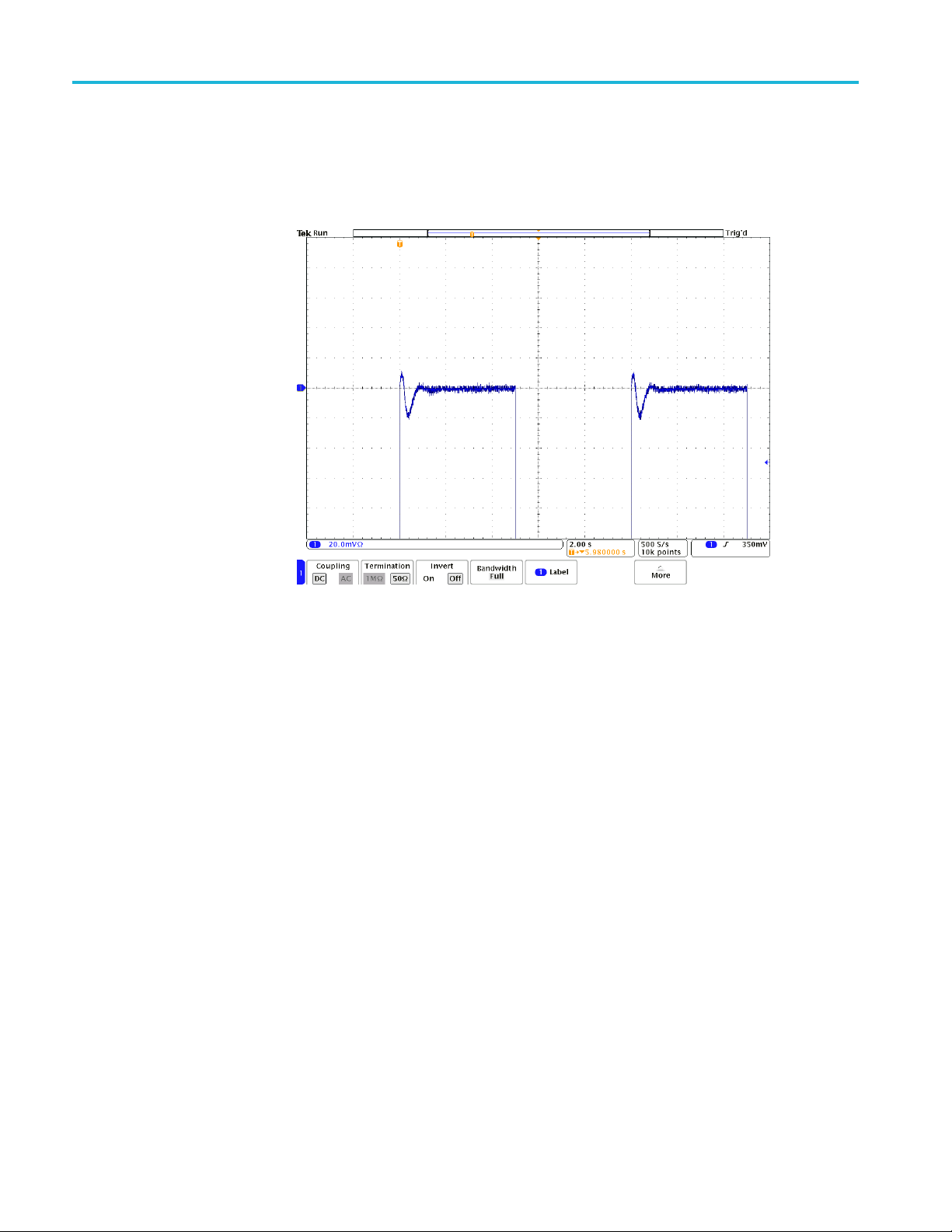
When attempting to capture a signal that has a frequency near 43.5 Hz, 87.0 Hz, or
130.5 Hz, the display might show aliasing. If you cannot avoid these frequencies,
the off
selected to not alias at 50 Hz or 60 Hz.
on ratio (CMRR) and lets you see small signals that would otherwise
ies products implement a n offset correction algorithm to minimize
set correction should be disabled. The sample rate of the digital filter was
Figure 10: Digital filter aliasing
To disable the offset correction algorithm, hold down the MENU button on the
controller and momentarily press the CLAMPING button. The OVERRANGE
indicator on the controller should blink two times. To re-enable the correction,
repeat the operation; the OVERRANGE indicator should blink once. Turning off
the correction is temporary; when the measurement system is removed/re-attached,
the offset correction is re-enabled.
TIVM Series Measurement System User Manual 15
Page 34
Operating information
Another source
of aberrations is introduced when the signal is below the cutoff
frequency of the digital filter (5.0 Hz). The following figure shows a close-up
view of the front edge of a 0.1 Hz 800 mV
square wave. These aberrations are
p-p
also created by the digital filter.
Figure 11: Digital filter aberrations (about 2.5% of V
p-p
)
The following figure shows the aberrations after the offset correction has been
disabled. When the offset correction is disabled, the system no longer corrects for
long-term drift due to temperature change and fiber movement.
16 TIVM Series Measurement System User Manual
Page 35
Operating information
1X/2X Range
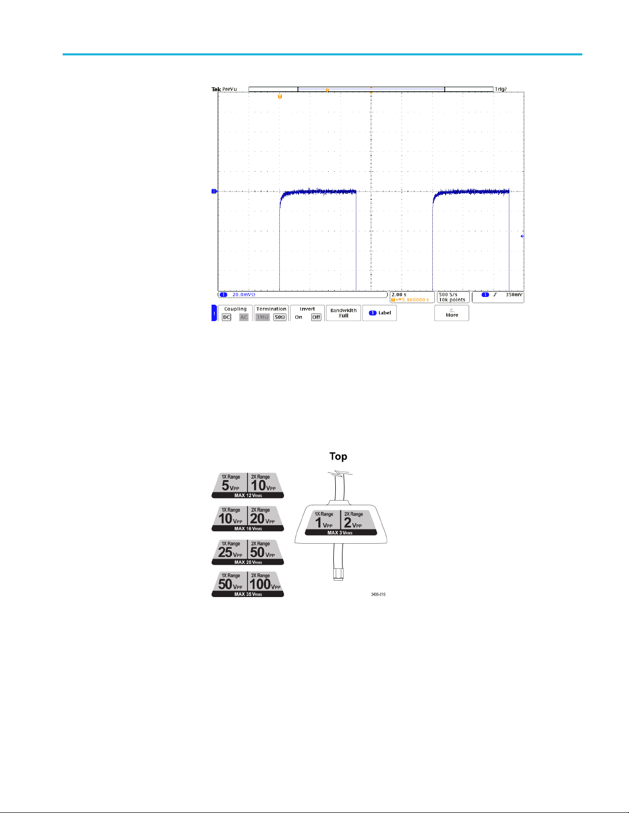
Figure 12
The top label of each sensor tip cable (IVTIP1X, IVTIP5X, IVTIP10X,
IVTIP25X, IVTIP50X) shows the dynamic range in peak-to-peak volts as shown
in the following figure.
Figure 13: Top sensor tip labels
: Digital filter aberrations after disabling offset correction
TIVM Series Measurement System User Manual 17
Page 36

Operating information
Auto Rang
For example, th
e IVTIP5X tip has a dynamic range of 5 V
when the 1X Range
p-p
is selected. This means that you can display a signal with a ±2.5 V differential
voltage. When the 2X Range is selected, the dynamic range increases from 5 V
to 10 V
(±5.0 V). Refer to the Linear differential input voltage range in the
p-p
p-p
specifications table for more information.
CAUTION. To avoid damaging the probe, do NOT exceed either the RMS OR
Peak Voltag
e ratings. The Maximum Non-Destruct Voltage limits (RMS and Peak
Vo ltage) do not increase when the 2X Range is selected. For the IVTIP5X, the
12 V
and ±21.5 Vpklimits are the same for the 1X or 2X Range.
rms
e
By default, the MSO/DPO5000, DPO7000, and MSO/DPO70000 Series
Oscilloscopes select the 1X or 2X Range automatically when you change the
V/div se
However, there are combinations of Range and V/div settings that cannot be
reached when Auto Range is selected. For these situations, select Manual Range
when full flexibility is desired.
tting. This hides the complexity of selecting the range from casual users.
18 TIVM Series Measurement System User Manual
Page 37

Operating information
Selecting a se
nsor tip cable
CAUTION. Avoid over-voltage conditions that can damage or degrade the sensor
head input termination by selecting the wrong sensor tip cable. The sensor head
SMA input is a 50 Ω terminated input. Selecting the correct sensor tip cable
attenuation factor is crucial to ensure that the sensor head input termination is not
degraded or damaged by an over-voltage condition. Select the sensor tip cable
that will p
This also provides the highest differential impedance to the circuit-under-test.
When sele
following questions:
What is t
(for example, under a fault condition)?
What is
can tolerate?
How la
What sensitivity do I need (for example, the minimum V/div setting)?
The following table will help you select the correct sensor tip. Start at the top of
the table and work down. Choose the first tip that meets all of your criteria.
rovide the highest attenuation possible for the signal being measured.
cting a sensor tip cable for a particular application, consider the
he maximum RMS/Peak Voltage at the test point being measured
the minimum differential loading (input resistance) that my circuit
rge of a signal do I want to display at one time on the oscilloscope?
le 6: Sensor tip selection table
Tab
Most sensitive
Sensor tip
IVTIP50X
IVTIP25X
IVTIP10X
IVTIP5X
IVTIP1X
1
On 1X range
2
On 2X range
V/div setting
50 mV/div ±50 V (100 V
25mV/div ±25V(50V
10mV/div ±10V(20V
5 m V/div ±5 V (10 V
1 mV/div ±1 V (2 V
Differential input specifications
imum
Max
)
non-destruct
voltage (RMS)
35 V
rms
25 V
rms
16 V
rms
12 V
rms
3V
rms
1
range
2
p-p
)
p-p
)
p-p
)
p-p
)
p-p
Linear voltage
imum
Max
non-destruct
voltage (Peak)
200 Vpk
107.5 Vpk
43 Vpk
21.5 Vpk
4.3 Vpk
Differential input
resistance
2.5 k
1.25 k
500
250
50
TIVM Series Measurement System User Manual 19
Page 38

Operating information
Output clampi
ng
Sensor tip loading
The measurement system has a selectable output clamping feature. Push the
button on the controller to enable or disable the output clamping feature. When
enabled (ind
the measurement system into the oscilloscope input. It allows you to increase the
vertical sensitivity without over-driving or saturating the oscilloscope input.
Each of the sensor tip cables (IVTIP1X, IVTIP5X, IVTIP10X, IVTIP25X,
IVTIP50X) has a differential input resistance listed on the bottom labels as shown
in the following figure.
icator is on), the output clamping limits the output voltage swing of
Figure 14: Bottom sensor tip labels
It is important to understand the impact of the tip loading on the DUT. For
mple, the IVTIP5X tip has a differential input resistance of 250 Ω.Ifyou
exa
choose the IVTIP25X tip, the differential input resistance increases to 1.25 kΩ.
Refer to the Input resistance/capacitance section in the specifications table for
more information. The sensor tip cables are specially designed to act as a common
mode choke that helps reduce the common mode loading.
NOTE. The coaxial (common) shield of the sensor tip cable should always be
onnected to the lowest impedance point (usually a circuit common or power
c
supply rail) in the circuit-under-test (relative to the sensor tip cable/center
conductor) to obtain the most accurate waveform.
20 TIVM Series Measurement System User Manual
Page 39

Probe compensation
Deskew
Operating information
The DPO7000 and MSO/DPO70000 Series oscilloscopes have a Compensate
Probe feature accessible from the Probe Setup window. Pressing this button
always results in a failure because the input resistance of the TIVM sensor tips is
too low and cannot be driven by the calibrator output of the oscilloscope. The
accuracy of
though the Compensate Probe feature fails.
Each oscilloscope family has a unique way of allowing you to adjust the timing
relationship between signals acquired between different probes. Consult the user
manual or online help o f the oscilloscope for specific directions needed to deskew
the probe. The 3 m and 10 m measurement systems have a propagation delay of
approximately 35 ns and 68 ns respectively. The actual propagation delay is
measur
the TIVM system is still guaranteed on these oscilloscopes even
ed on each measurement system and is stored within each unit.
Input offset
The me
This allows you to view a portion of the signal that is off-screen. One of the
controls on the oscilloscope can be assigned this function.
The minimum/maximum offset is different for each sensor tip cable. It is the same
when the 1X or 2X Range is selected; it is also the same for all V/div settings.
Refer the following input offset table.
Table 7: Input offset
Se
IVTIP1X ±2 V
IVTIP5X ±10 V
VTIP10X
I
IVTIP25X ±50 V
IVTIP50X ±100 V
asurement system provides a user-adjustable, input referred offset voltage.
nsor tip cable
put offset voltage
In
20 V
±
TIVM Series Measurement System User Manual 21
Page 40

Operating information
22 TIVM Series Measurement System User Manual
Page 41
Application examples
The following examples are provided to help you become familiar with the TIVM
Series IsoVu measurement system and to achieve the best performance for your
application.
Example 1: H
igh-side V
measurement
GS
Advancements in the components used in switching power supplies have made
characterizing the performance of these power supplies increasingly difficult and
challengi
V
GS
good CMRR is required from the test system. The following figure shows an
example of this circuit.
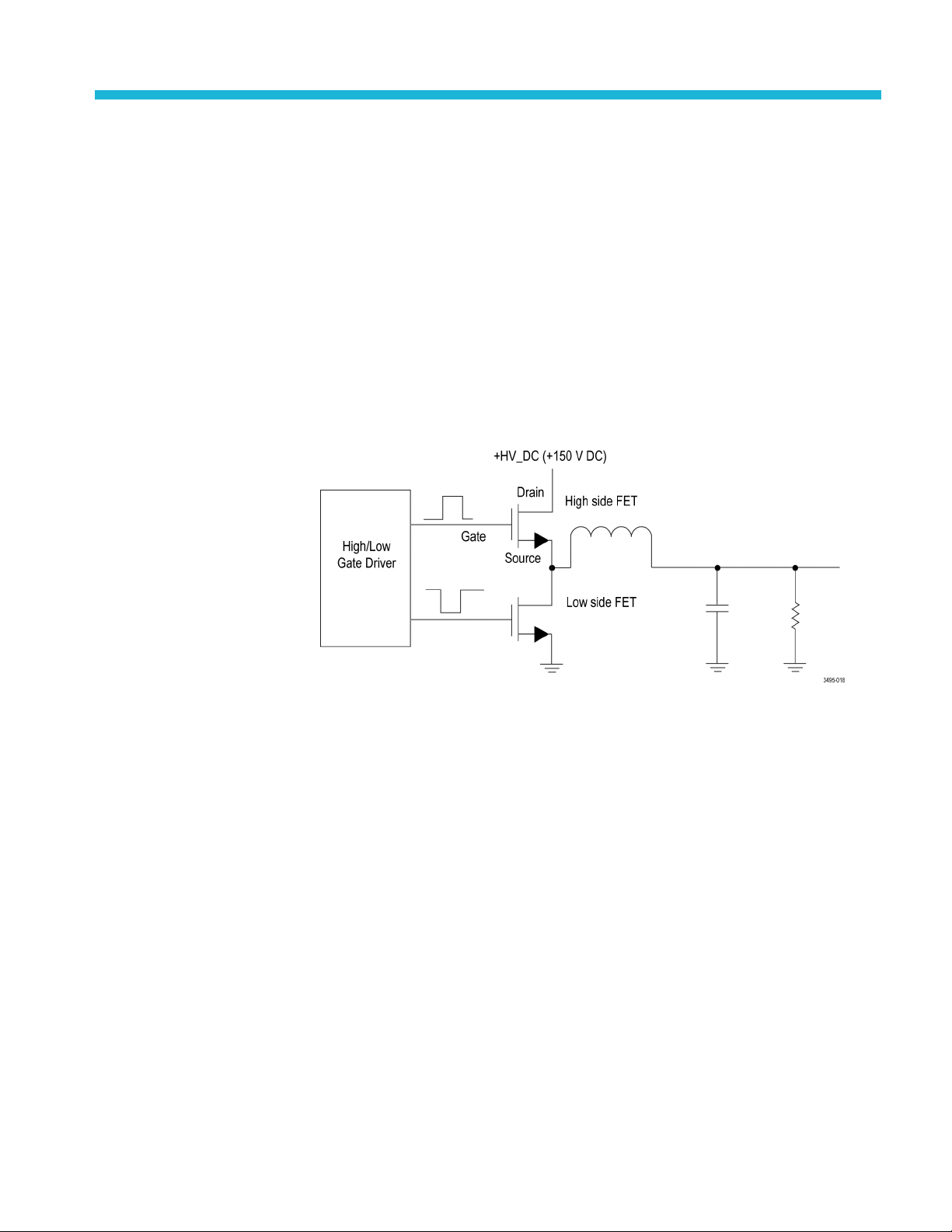
Figure 15: Half-bridge circuit showing the gate, source, and drain of the high-side
FET
ng. A particularly challenging measurement is measuring the high-side
in a half bridge. To accurately make this measurement, an exceptionally
In this type of circuit, the gate-source voltage is of interest because the rate at
which the device switches is determined by the gate drive characteristics. The
reference node for this measurement is the high-side source node, which switches
tween the input supply voltage and the local PCB ground during operation. In a
be
measurement system without sufficient CMRR, this rapidly changing common
mode voltage results in interference which obscures the measurement. It is
important to note that the CMRR for all measurement systems is frequency
dependent; however, the frequency that is critical for this measurement is not
the switching frequency, but the frequency corresponding to the edge rate. For
example, to accurately characteriz e a power supply with a switching frequency
of 100 kHz and an edge rate of 1 ns, a system with good CMRR at 350 Mhz is
necessary because of the edge speed.
TIVM Series Measurement System User Manual 23
Page 42

Application examples
In this example
, the gate drive voltage could be about 5 V but usually has some
ringing and overshoot which are important to characterize. For this measurement,
it is appropriate to use a 10X tip with a 10 V
input (on the 1X range) so that
p-p
the signal is fully resolved and is within the dynamic range of the measurement
system.
To get the best CMRR from your TIVM Series IsoVu measurement system, pay
careful attention when connecting the measurement system to the DUT. This
connection should preserve the signal fidelity and shield the signal from unwanted
interfere
nce. To achieve the best performance from the measurement system, use
an MMCX connector as close to the test point as possible. The MMCX connectors
are available from a number of vendors and are relatively inexpensive. The key
attributes of these connectors, which make them excel for this application, are
their compact footprint and solid metal body. The solid metal body and gold
contacts provide a w ell-shielded signal path.
The IsoVu input provides a floating differential measurement with differential
input resistance from 50 Ω to 2.5 kΩ, depending on the tip attenuation. In the
VGS mea
surement example the 10X tip with a 500 Ω input impedance is used.
The common mode resistance is extremely high, greater than G Ω, in parallel
with a small capacitance from the tip cable shield to ground, typically 2 pF or
less. Keep these impedances in mind when determining how to connect the
measurement system to the DUT. The source node in the h alf bridge circuit is a
very low impedance point, and is the point that should be used to drive the tip
e shield capacitance. The gate driver output, which is also a low impedance
cabl
node (but not as low impedance as the source), should be used to drive the center
contact of the sensor tip cable. The input impedance of the sensor tip cable for the
10X tip is 500 Ω relative to the shield – not to ground.
An example of a measurement that is possible with IsoVu is measuring the
high-side turn-on characteristics shown in the following figure.
Figure 16: High-side turn-on characteristics
24 TIVM Series Measurement System User Manual
Page 43
Application examples
Exampl
In general ther
e a re three characteristic regions of interest of the turn-on waveform
(See Figure 16.):
The first regio
nistheC
charge time.
GS
The second region is the Miller Plateau (the time required to charge the
gate-drain
increases as V
The third re
Miller capacitance (C
increases.
DS
gion occurs when the channel is in conduction and the gate
chargesuptoitsfinal value.
Due to the r
apid rise of the voltage on the switch node during the high side
turn-on, there can be very high frequency and high amplitude common mode
voltage changes during the transition. If this common mode voltage transient is
not rejected, then the measurement of the high-side V
not possible.
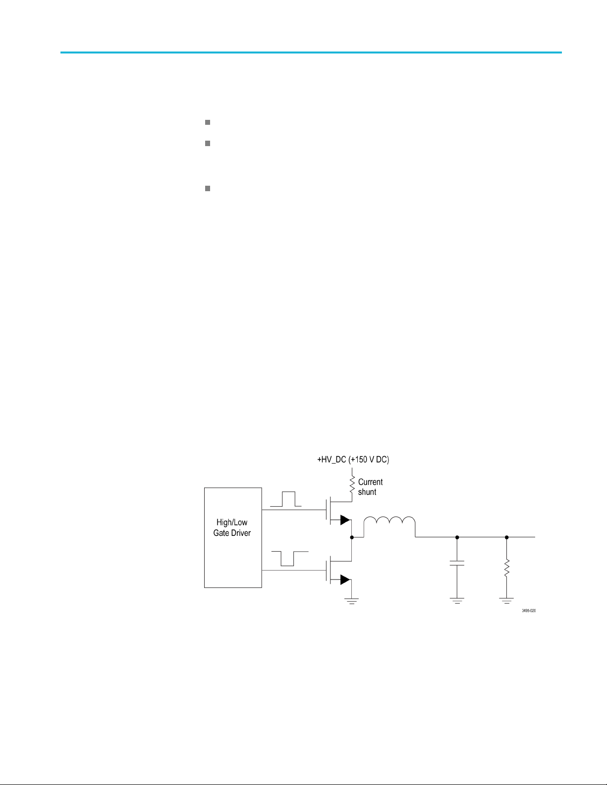
e 2: High-side drain current measurement
Current sensing is a critical measurement in many applications. Using the half
bridge circuit again as an example, measuring the high-side drain current, I
y challenging particularly during startup. At startup, there can be common
be ver
mode voltage transients due to parasitic inductance in the supply leads in addition
to large current swings. Inserting a conventional current probe into the circuit at
this point would require adding excessive inductance, which might limit circuit
performance. Using a small value resistor as a current shunt makes it possible
to take very high frequency current measurements with minimal additional
edance in the drain connection. (See Figure 17.)
imp
), and is VDSdependent. The charge time
GD
during the transition is
GS
,can
D
Figure 17: High side current shunt
TIVM Series Measurement System User Manual 25
Page 44

Application examples
In a typical app
current of 1 A, resulting in a voltage swing of 0.25 V, which can be measured with
the measurement system using a 1X or 5X tip. A typical surface mount resistor
can have a series inductance of less than 0.2 nH and series capacitance of less than
0.04 pF, resulting in much lower impedance at high frequency than could be
obtained with a conventional current probe.
Figure 18: SMT resistor model
Go to http://www.vishay.com/docs/60107/freqresp.pdf for models of different
types o
In general, surface mount resistors have fairly low power ratings; care must
be take
Several vendors make very high power parts that can be used when high
power dissipation is required. For example, the RP0402CB-R500FN-2Q from
Barry Industries (http://www.barryind.com/)isa1.0W,0.5Ω 0402 resistor
on an AIN substrate, or the RP0402CB-R500FN-2Q from US Microwaves
(http://www.usmicrowaves.com/)isa1.5W,1Ω resistor on a BeO substrate.
f surface mount resistors.
n not to exceed these ratings when using them as current shunts.
lication, a 0.25 Ω resistor might be used to measure a transient
Example 3: ESD troubleshooting
Many devices and systems can be negatively affected by ESD discharges.
oubleshooting problems that occur during an ESD discharge can be very
Tr
difficult. A piece of test equipment connected to a device undergoing ESD testing
has to not only withstand the ESD discharge, but it also has to reject interference
caused by the rapid changes in potential on the DUT during an ESD discharge test.
For example, consider using the standard human body model of 100 pF and
1500 Ω. If the DUT is being tested to 4 kV and has a capacitance of 50 pF, the
test equipment will be exposed to a voltage change of more than 1 kV in tens
of nanoseconds.
26 TIVM Series Measurement System User Manual
Page 45

Application examples
Figure 19: ESD discharge test example
In this example, if it is suspected that there is a glitch on the communication bus
betwee
the signals on the bus and to inspect them during the discharge. Because the
measurement system uses Galvanic isolation, it rejects any interference from the
ESD transient and tolerates the high common mode voltage during the discharge;
the communication bus can be monitored throughout the ESD discharge and any
irregularities can be investigated without interference from the ESD discharge.
n two devices during the ESD discharge, then it is helpful to connect to
TIVM Series Measurement System User Manual 27
Page 46

Application examples
28 TIVM Series Measurement System User Manual
Page 47

Reference information
Specification
Table 8: Warranted specifications
Characteristic Description
Propagation delay (Warranted) 3 m fiber length: 35 ns ±5 ns (actual propagation delay is measured and stored within each unit)
s
The following tables list the specifications for the measurement system. The
specifications are guaranteed unless otherwise indicated.
The performance limits in this specification are valid with these conditions:
The instrument must be in an environment with temperature, altitude, and
humidity within the operating limits described in these specifications.
The instrument must have had a warm-up period of at least 20 minutes.
The measurement system is powered from a TekVPI compatible oscilloscope.
Warranted specifications describe guaranteed performance with tolerance limits or
certain type-tested requirements.
The performance verification procedures for the Propagation delay are listed later
in this document. (See page 47, Propagation delay.)
10 m fiber length: 68 ns ±7 ns (actual propagation delay is measured and stored within each
unit)
le 9: Electrical specifications
Tab
Characteristic Description
Controller output
termination
Controller output coupling DC coupled
Range attenuation
Terminate the controller output into 50
Sensor tip cable/adapter
Sensor head input SMA 1X (÷1) 2X (÷2)
IVTIP1X, 1X Sensor tip cable 1X (÷1) 2X (÷2)
IVTIP5X, 5X Sensor tip cable 5X (÷5) 10X (÷10)
IVTIP10X, 10X Sensor tip cable 10X (÷10) 20X (÷20)
IVTIP25X, 25X Sensor tip cable 25X (÷25) 50X (÷50)
IVTIP50X, 50X Sensor tip cable 50X (÷50) 100X (÷100)
1X range 2X range
TIVM Series Measurement System User Manual 29
Page 48
Reference information
Table 9: Electrical specifications (cont.)
Characteristic Description
Input
resistance/capacitance
(attached to sensor head,
50 termination), (Ty pical)
Maximum non-destructive
differential input voltage
range, (Typical)
CAUTION. To avoid
damaging the measurement
system, be aware of the
input voltage limits; this
specification applies to
both the 1X Range and 2X
Range.
Linear differential input
voltage range, (Typical)
Output clamping range
(Input referred)
(Typ ical)
Output clamping overdrive
recovery (Typical)
Sensor tip cable/adapter
Sensor head input SMA 50 ±2%
IVTIP1X, 1X Sensor tip cable 50
IVTIP5X, 5X Sensor tip cable 250
IVTIP10X, 10X Sensor tip cable 500
IVTIP25X, 25X Sensor tip cable 1.25 k
IVTIP50X, 50X Sensor tip cable 2.5 k
Sensor tip cable/adapter
Sensor head input SMA
IVTIP1X, 1X Sensor tip cable
IVTIP5X, 5X Sensor tip cable
IVTIP10X, 10X Sensor tip cable
IVTIP25X, 25X Sensor tip cable
IVTIP50X, 50X Sensor tip cable
Sensor tip cable/adapter
Sensor head input SMA
IVTIP1X, 1X Sensor tip cable
IVTIP5X, 5X Sensor tip cable
IVTIP10X, 10X Sensor tip cable
IVTIP25X, 25X Sensor tip cable
IVTIP50X, 50X Sensor tip cable
Sensor tip cable/adapter Clamping on,
Sensor head input SMA
IVTIP1X, 1X Sensor tip cable
IVTIP5X, 5X Sensor tip cable
IVTIP10X, 10X Sensor tip cable
IVTIP25X, 25X Sensor tip cable
IVTIP50X, 50X Sensor tip cable
<20ns
Resistance
V
rms
3 V 4.3 Vpk
3 V 4.3 Vpk
12 V 21.5 Vpk
16 V 43 Vpk
25 V 107.5 Vpk
35 V 200 Vpk
Clamping Off,
1X Range
±V peak
(DC + peak AC)
±0.5 V ±1 V
±0.5 V ±1 V
±2.5 V ±5 V
±5 V ±10 V
±12.5 V ±25 V
±25 V ±50 V
1X Range
± 100 mV ± 200 mV
± 100 mV ± 200 mV
± 500 mV ± 1 V
±1V ±2V
±2.5V ±5V
±5V ±10V
Capacitance
NA
NA
< 1pF
< 1pF
< 1pF
< 1pF
V peak
Clamping Off,
2X Range
±V peak
(DC + peak AC)
Clamping on,
2X Range
30 TIVM Series Measurement System User Manual
Page 49

Table 9: Electrical specifications (cont.)
Characteristic Description
System noise
(Typ ical)
DC gain accuracy1, (Input referred) (Typical)
Differential DC gain
accuracy
80% to 100% of full
scale in 2X Range:
DC offset error voltage
2
(Input referred)
(Typ ical)
Input offset voltage range
(Typ ical)
Input offset voltage
accuracy (Typical)
Small signal rise time (10%
to 90%) (Typical)
(SMA input and with sensor
tip cables)
Small signal frequency
response
(Typ ical)
(SMA input and with sensor
tip cables)
1 GHz system noise (input referred)
Sensor tip cable/adapter
Sensor head input SMA
IVTIP1X, 1X Sensor tip cable
IVTIP5X, 5X Sensor tip cable
IVTIP10X, 10X Sensor tip cable
IVTIP25X, 25X Sensor tip cable
IVTIP50X, 50X Sensor tip cable
±3% ± DC offset error voltage ± input offset accuracy error
±5% ± DC offset error voltage ± input offset accuracy error
Sensor tip cable/adapter
Sensor head input SMA
IVTIP1X, 1X Sensor tip cable
IVTIP5X, 5X Sensor tip cable
IVTIP10X, 10X Sensor tip cable
IVTIP25X, 25X Sensor tip cable
IVTIP50X, 50X Sensor tip cable
Sensor tip cable/adapter Input offset voltage range
Sensor head input SMA
IVTIP1X, 1X Sensor tip cable
IVTIP5X, 5X Sensor tip cable
IVTIP10X, 10X Sensor tip cable
IVTIP25X, 25X Sensor tip cable
IVTIP50X, 50X Sensor tip cable
±5%
TIVM1/TIVM1L
TIVM05/TIVM05L
TIVM02/TIVM02L
TIVM1/TIVM1L DC to 1GHz
TIVM05/TIVM05L DC to 500 MHz
TIVM02/TIVM02L DC to 200 MHz
1X Range 2X Range
<0.8mV
<0.8mV
<4mV
rms
<8mV
rms
<20mV
<40mV
rms
rms
rms
rms
<1.6mV
<1.6mV
<8mV
rms
<16mV
<40mV
<80mV
1X Range 2X Range
±2 mV ±4 mV
±2 mV ±4 mV
±10 m V ±20 mV
±20 m V ±40 mV
±50 m V ±100 mV
±100 mV ±200 mV
±2 V
±2 V
±10 V
±20 V
±50 V
±100 V
Rise time
350 ps
700 ps
1.8 ns
-3 dB bandwidth
Reference information
rms
rms
rms
rms
rms
TIVM Series Measurement System User Manual 31
Page 50

Reference information
Table 9: Electrical specifications (cont.)
Characteristic Description
Common mode rejection ratio (Typical)
Sensor tip cable/adapter DC
IVTIP1X, 1X Sensor tip
> 120 dB 120 dB 110 dB 100 dB 90 dB
cable
IVTIP5X, 5X Sensor tip
> 120 dB 120 dB 110 dB 100 dB 90 dB
cable
IVTIP10X, 10X Sensor
> 120 dB 120 dB 110 dB 100 dB 90 dB
tip cable
IVTIP25X, 25X Sensor
> 120 dB 110 dB 100 dB 100 dB 90 dB
tip cable
IVTIP50X, 50X Sensor
> 120 dB 100 dB 90 dB 90 dB 80 dB
tip cable
MMCX-to 0.1 in
> 120 dB 70 dB 60 dB 40 dB 30 dB
(2.54 mm) square pin
adapter with sensor tip
cable.
MMCX-to 0.062 in
> 120 dB 70 dB 60 dB 40 dB 30 dB
(1.57 mm) square pin
adapter with sensor tip
cable.
Common mode voltage
2 kVpk (2 kV CAT I, 1000 V CAT II)
range
Common mode resistance
N.A. due to Galvanically isolation (fiber optic connection)
(Typ ical)
Common mode
capacitance
3
~2 pF
(Typ ical)
Overload indicator range
(Typ ical)
Sensor tip cable/adapter Overload indicator On
Sensor head input SMA
IVTIP1X, 1X Sensor tip cable
IVTIP5X, 5X Sensor tip cable
IVTIP10X, 10X Sensor tip cable
IVTIP25X, 25X Sensor tip cable
IVTIP50X, 50X Sensor tip cable
1
The difference between the measured DC gain and the nominal DC gain, divided by the nominal DC gain and expressed as a percent.
2
The input referred offset error voltage when the input is shorted and the probe input offset is set to 0 volts
3
The capacitance between the sensor head and a reference plane. The sensor head is placed six inches (15.25 cm) above the reference plane.
100 MHz 200 MHz 500 MHz
<-3VorVin>+3V
V
in
<-3VorVin>+3V
V
in
<-12VorVin>+12V
V
in
<-16VorVin>+16V
V
in
<-25VorVin>+25V
V
in
V
<-35VorVin>+35V
in
1GHz
32 TIVM Series Measurement System User Manual
Page 51

Reference information
Table 10: Physi
Characteristic Description
Net weight
Sensor tip cables 0.025 kg (0.055 lb)
Sensor head 0.363 kg (0.8 lb)
Controller box 0.816 kg (1.8 lb)
TekVPI Comp box 0.57 kg (0.125 lb)
Sensor tip cable length 15.24 cm (6.0 in)
Fiber cab
TekVPI cable length
Overal
le length
TIVM1, TIVM02, TIVM05
TIVM1L, TIVM02L, TIVM05L
l length and tolerances
Comp b
Controller to sensor head
(TIVM1, TIVM02, TIVM05)
Controller to sensor head
VM1L, TIVM02L, TIVM05L)
(TI
cal specifications
ox to controller
(Weight does not include accessories and packaging.)
3m(9.84
10 m (32.
55.88 c
0.558
length.
2.9718 m ±10.2 cm (117 in ±4 in)
9.982 m ±10.2 cm (393 in ±4 in)
ft)
81 ft)
m(22in)
8 m ±3.81 cm (22 in ±1.5 in) shoulder-to-shoulder, Boot area included in the overall
Dimensional drawings
Figure 20: Sensor head dimensions with probe tip cover
TIVM Series Measurement System User Manual 33
Page 52

Reference information
Figure 21: Sensor head dimensions without probe tip cover
Figure 22: Controller dimensions
34 TIVM Series Measurement System User Manual
Page 53

Figure 23: Comp box dimensions
Reference information
e 24: Probe tip adapter dimensions
Figur
TIVM Series Measurement System User Manual 35
Page 54

Reference information
IsoVu measurement system block diagram
The following figure shows a block diagram of the IsoVu measurement system.
Figure 25: Block diagram
The common mode resistance and capacitance to earth ground is shown in the
figure. (See Figure 25.) The common mode resistance is shown as R parasitic and
is essentially infinite with the IsoVu measurement system since it is galvanically
isolated and can be ignored. The common mode coupling capacitance to earth
ground and the surrounding circuit is shown as the Parasitic Bridging Capacitance
(Cpara
sensor head is placed six (6) inches (15.25 cm) above a ground plane.
sitic). This parasitic capacitance will be approximately 2 pF when the
To m in
following items:
imize the effects of common mode capacitive loading consider the
ever possible, choose a reference point in the circuit-under-test that is
When
static potential with respect to earth ground.
nect the coaxial (common) shield of the sensor tip cable to the lowest
Con
impedance point of the circuit.
creasing the physical distance between the sensor head and any conductive
In
surface will reduce the parasitic capacitance.
hen using multiple IsoVu systems to measure different points in the circuit
W
that do not have the same common mode voltages, keep the sensor heads
separated to minimize the capacitive coupling.
36 TIVM Series Measurement System User Manual
Page 55
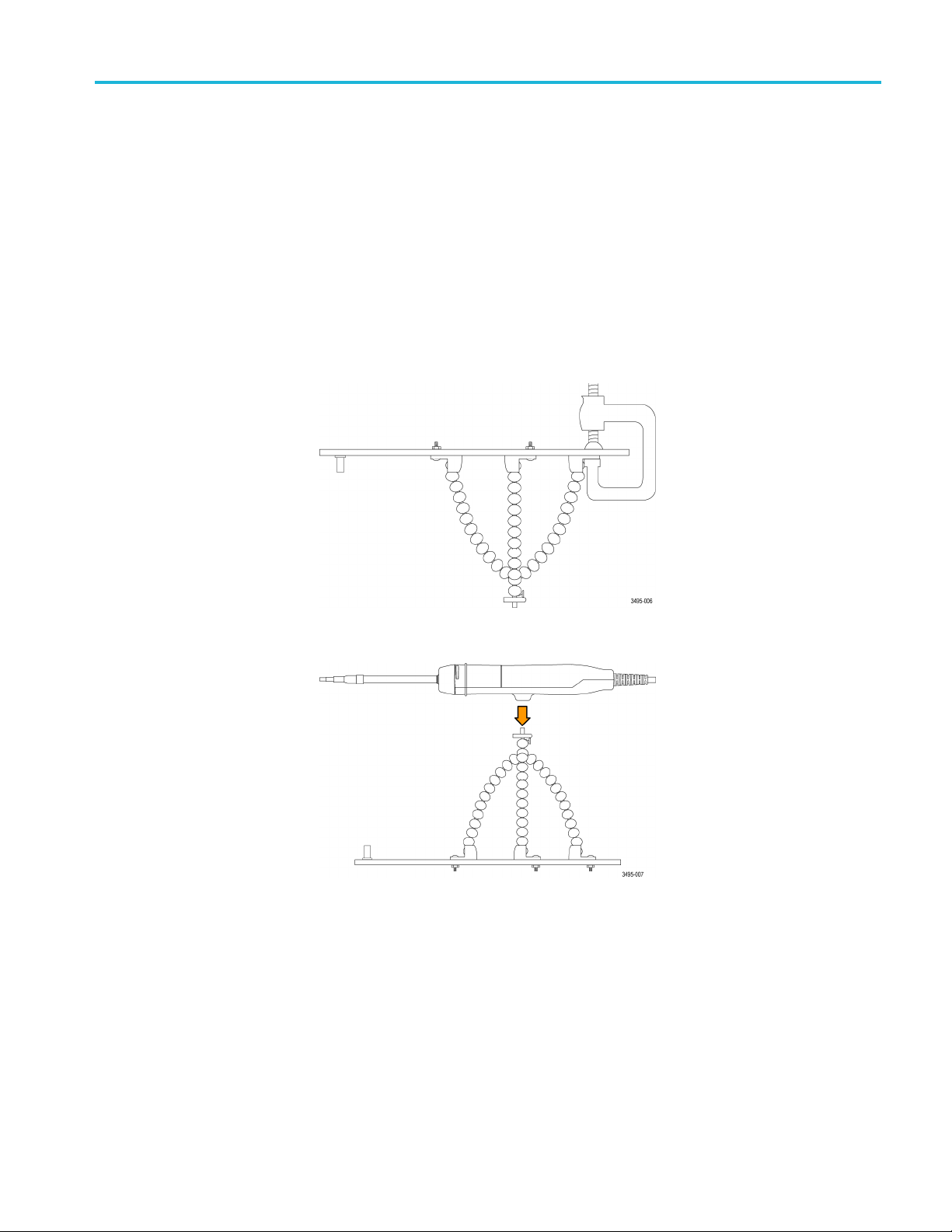
Tripods
Reference information
Tektronix provides two tripods as accessories with the measurement system. T he
Flexible tripod holds the sensor head while connected to the DUT. The Probe tip
tripod supports the sensor tip cables while they are connected to adapters on
the circuit board.
Flexible tr
ipod
The tripod can be connected to the DUT in different ways. You can secure the
tripod to the DUT using optional feet. T he feet can be clamped or attached to the
DUT using common screws. This allows you to install the tripod upside down or
right side
Figure 26: Installing the flexible tripod under the DUT.
up as shown in the following figures.
Figure 27: Connecting the sensor head to the top of the DUT with the flexible tripod.
Probe tip tripod
TIVM Series Measurement System User Manual 37
Use the probe tip tripod to connect the sensor tip cables to adapters on the circuit
board. This tripod has flexible hinges to easily position the probe tip cable above
the adapter on the circuit board. Tektronix recommends gluing the tripod in place
on the circuit board to provide additional support for the sensor tip cables. The
following figure shows an example of connecting to an adapter on the circuit
board with the tripod; it reduces stresses on the test point.
Page 56

Reference information
Figure 28: Connecting to an adapter on the circuit board with the probe tip tripod
38 TIVM Series Measurement System User Manual
Page 57

Installing the probe tip adapters
Tektronix provides two probe tip adapters to connect the sensor tip cables to
pins on the circuit board. The MMCX-to-0.1-inch (2.54 cm) pitch adapter and
the MMCX-to-0.062-inch (1.57 mm) pitch adapter.
One end of each adapter has an MMCX socket for connection to an IsoVu tip
cable. The other end of the adapter has a center pin socket and four common
(shield) sockets around the outside of the adapter. Notches on the adapters can be
used to loc
the same, the main difference is the spacing of the pins on the circuit board.
ate the shield sockets. The procedure for installing these adapters are
Reference information
To insta l
the signal source pin on the circuit board. Use the notch on the adapter to align
one of the shield sockets to the common pin on the circuit board. The following
figures show examples of lining up the adapters on the circuit board.
To achieve the best electrical performance, especially the CMRR performance
and EMI susceptibility, place the probe tip adapter as close as possible to the
circuit board.
l the adapters onto the square pins, line up the center of the adapter with
Figure 29: Lining up the MMCX-to-0.1-inch (2.54 mm) adapter on the circuit board
TIVM Series Measurement System User Manual 39
Page 58
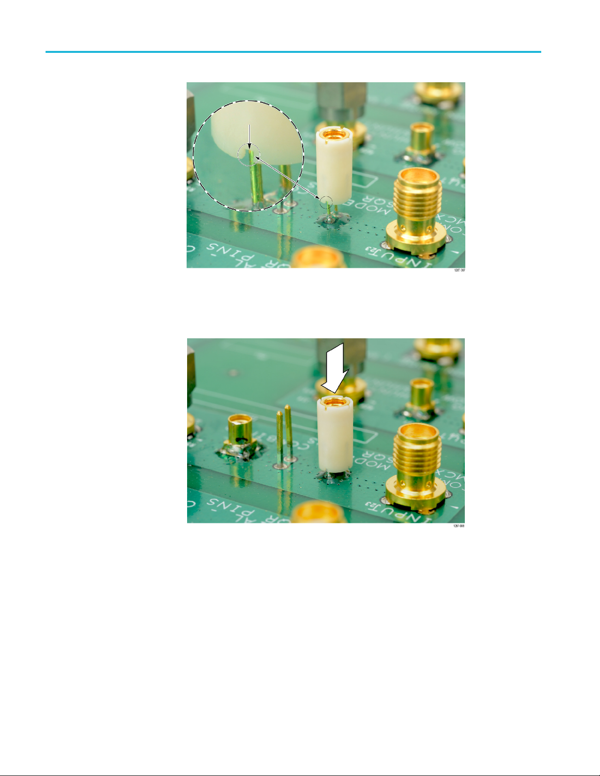
Reference information
Figure 30: Lining up the MMCX-to-0.062-inch (1.57 mm) adapter on the circuit board
After lining up the adapters gently push down on the adapter to seat it in place on
the circuit board.
Figure 31: Pushing the MMCX-to-0.062-inch (1.57 mm) adapter in place
40 TIVM Series Measurement System User Manual
Page 59
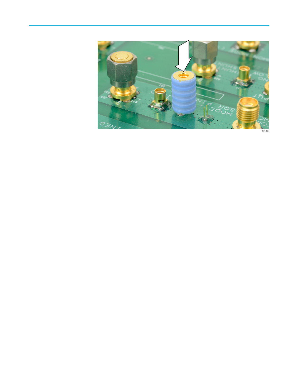
Reference information
Figure 32: Pushing the MMCX-to-0.1-inch (2.54 mm) adapter in place
When the adapters are firmly in place on the circuit board connect the sensor tip
cable to the top of the adapter while using the probe tip tripod to ease the tension
off the probe tip cable and adapter. (See Figure 28 on page 38.)
TIVM Series Measurement System User Manual 41
Page 60

Reference information
Installing the square pins on the circuit board
The following figure shows the recommended cle arance r equire ments for
connecting the adapters to the square pins on the circuit board. The bottoms
of the adapters are shown at the top.
Figure 33: Adapter clearance requirements
42 TIVM Series Measurement System User Manual
Page 61

Reference information
The 0.025-inch
board. Some square pins might have headers installed on the circuit board.
Tektronix recommends removing the plastic spacer from the square pins to gain
closer access to the circuit board as shown in the following figure to achieve the
best electrical performance, especially the CMRR. You might need to use a pair of
tweezers to remove the spacer as shown in the figure.
(0.635 mm) square pins should already be located on the circuit
34: Removing the header from square pins on the circuit board
Figure
onix provides a set of solder pins (0.018-inch (0.46 mm) diameter) to install
Tektr
on the circuit board for use with the MMCX to 0.062-inch (1.57 mm) adapter.
Use the soldering aide tool accessory (Tektronix part number, 003-1946-xx) to
install these pins on the circuit board.
NOTE. The solder pins are extremely small and can be challenging to handle.
Tektronix recommends using tweezers and a magnifying tool when installing
pins on the circuit board.
the
The solder pins can be installed around a surface mounted component on the
rcuit board, but adequate clearance should be maintained for a good electrical
ci
connection for the adapter. (See Figure 33 on page 42.)
OTE. The coaxial (common) shield of the sensor tip cable and tip adapters
N
should always be connected to the lowest impedance point (usually a circuit
common or power supply rail) in the circuit-under-test (relative to the sensor tip
cable/center conductor) to obtain the most accurate waveform.
TIVM Series Measurement System User Manual 43
Page 62
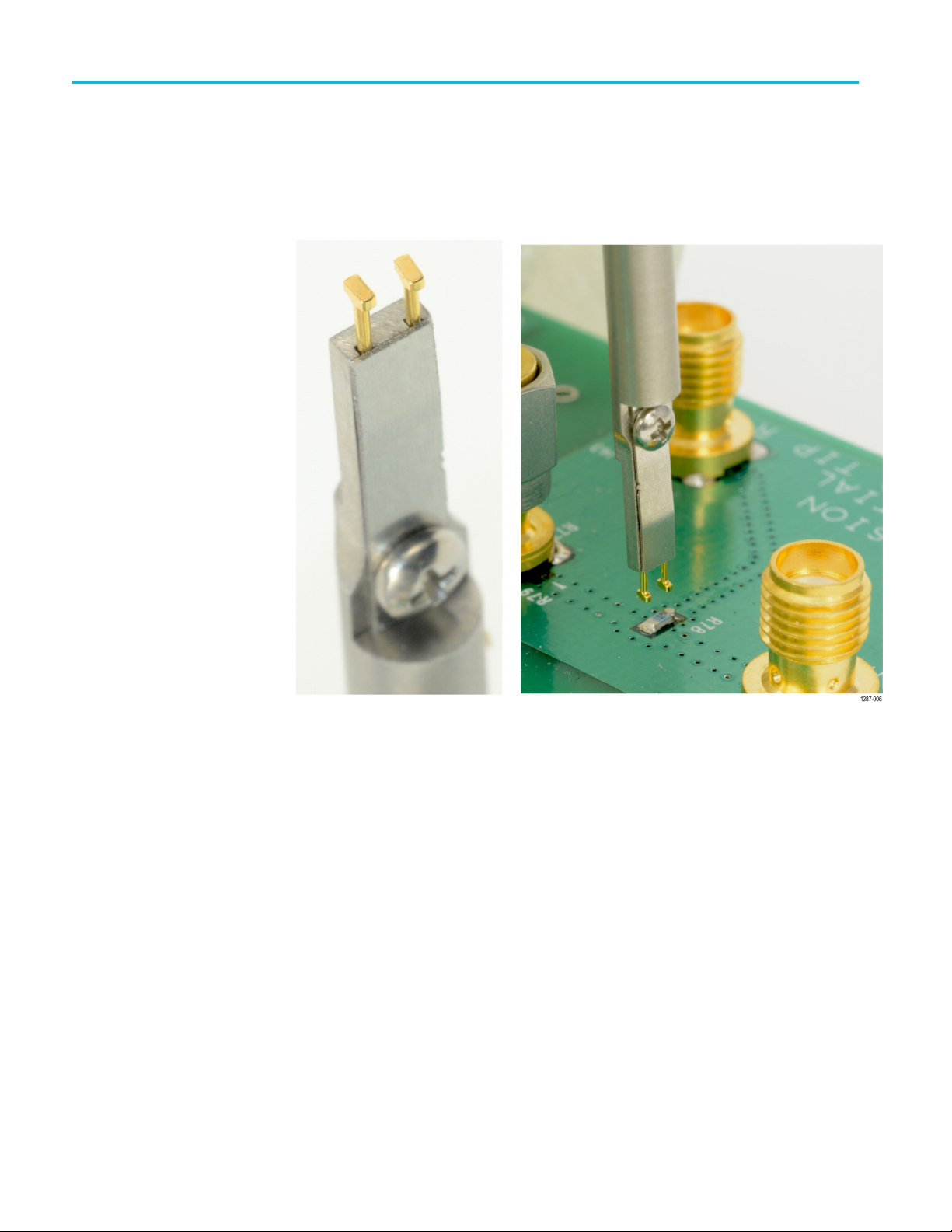
Reference information
Use the followi
circuit board:
1. Carefully ins
following illustration.
ng steps to install the solder pins using the soldering aide on the
ert t he solder pins into the soldering aide as shown in the
Figure 35: Using the soldering aide to install the square pins on the circuit board
2. Use the soldering aide to hold the square pins in place while soldering the
square pins to the circuit board.
3. If necessary apply a small amount of adhesive to further strengthen the
connection to the c i rcuit board. However, keep the height of the adhesive to a
minimum to provide good electrical contact for the adapter. (See Figure 33.)
44 TIVM Series Measurement System User Manual
Page 63

User service
Service offerings
Tektronix provides service to cover repair under warranty and other services that
are designed to meet your specific service needs.
Whether providing warranty repair service or any of the other services listed
below, Tektronix service technicians are well equipped to service the IsoVu
measurement system. Services are provided at Tektronix Service Centers and
on-site at your facility, depending on your location.
Warranty
repair service
Calibration and repair
service
Preventive maintenance
Tektronix warrants this product as described in the warranty statements at the front
of this manual. Tektronix technicians provide warranty service at most Tektronix
service locations worldwide. The Tektronix Web site provides information on all
service
In addition to warranty repair, Tektronix Service offers calibration and other
services that provide cost-effective solutions to your service needs and quality
stand
worldwide by the leading-edge design, manufacturing, and service resources of
Tektronix to provide the best possible service.
CAUTION. To prevent damage to the measurement system, do not expose it to
spr
head when cleaning the exterior.
locations worldwide.
ards compliance requirements. Tektronix instruments are supported
ays, liquids, or solvents. Avoid getting moisture inside the controller or sensor
TIVM Series Measurement System User Manual 45
Page 64

User service
Clean the exter
ior surfaces with a dry, lint-free cloth or a soft-bristle brush. If
dirt remains, use a soft cloth or swab dampened with a 75% isopropyl alcohol
solution. Use only enough solution to dampen the cloth or swab. Do not use
abrasive compounds on any part of the instrument.
Performance verification procedures
Use the following procedures to verify the performance of the IsoVu measurement
system. Before beginning the procedures, photocopy the test record and use it to
record the performance results. (See page 53, Test record.)
Required e
quipment
Table 11: Required equipment for performance verification
Description Minimum requirements Example product
Oscilloscope with TekVPI interface 1GHz,50 input support, fully compatible
Pulse generator 1 V
TIVM series 1X sensor tip cable As per description Tektronix IVTIP1X
MMCX Jack (female) to BNC
female adapter
The equipment r equired to perform the performance verification procedures are
shown in the following table.
Tektronix MDO4104C
with TekVPI interface
, <1ns risetime
p-p
As per description
Tektronix Tek-DPG
Fairview Microwave Product SKU: SM3610
Preparation
Prepare the equipment as follows:
1. Tur
n on the TekVPI oscilloscope.
2. Connect the Tek-DPG Deskew pulse generator into Channel 2 of the TekVPI
cilloscope.
os
3. Allow the test equipment to warm up for 20 minutes at an ambient temperature
f20°Cto30°C.
o
46 TIVM Series Measurement System User Manual
Page 65

Propagation delay
User service
This procedure verifies that the TIVM Series IsoVu measurement system is
functioning and meets the warranted propagation delay specification. The
propagation delay will be measured by first applying the output of the pulse
generator to the input of the oscilloscope and storing the captured waveform
as a referen
oscilloscope and the output of the pulse generator is connected to the input of the
measurement system. The delay is then measured between the saved reference
waveform and the acquired waveform of the measurement system.
NOTE. This procedure is valid for all versions of the TIVM Series IsoVu
measurement systems.
ce waveform. Next, the measurement system is connected to the
Create t he reference
waveform
Complete the following steps to create the reference waveform:
1. Connect the Tek-DPG Deskew Pulse Generator output BNC cable directly to
Channel 1 input of the TekVPI oscilloscope.
2. Enable Channel 2 and use the following setups:
Vertical Scale: 500 mV/div.
Vertical Position: -3 divisions
Set Termination: 1MΩ,
Coupling: DC
Bandwidth: FULL
skew: 0 seconds
De
3. Set the Trigger menu using the following setups:
Type: Edge
Source: CH2
Slope: Negative
Level: +1.50 V
Coupling: DC
4. Use the following setups for Channel 1.
Vertical Scale: 200 mV/div
Coupling: DC
Termination: 50 Ω
Bandwidth: FULL
TIVM Series Measurement System User Manual 47
Page 66

User service
Position: 0 (ce
Offset: -500 mV
Deskew: 0 seconds
5. Set the Horizontal menu to the following setups:
Horizontal Scale to 10 ns/div.
Horizontal Position: 40 ns
Acquire: Average 128
6. Set the Tek-DPG to the following setups:
0to-11kHzmode(Mode 1)
Output Enable: ON
7. The Channel 1 waveform should appear approximately on the center of the
oscilloscope display. If the waveform is not vertically centered in the display,
adjust the display as necessary to vertically center the waveform.
8. Use the following steps to save the Channel 1 waveform as the reference
waveform (R1).
Press MENU on the oscilloscope.
ntered)
Create the TIVM series
waveform
Select Save Waveform.
Source: CH1.
Destination: R1.
Select OK Save to save the Channel 1 waveform as reference waveform
R1. The new reference waveform should now be displayed on the
oscilloscope.
9. Disable the output of the Tek-DPG.
10. Disconnect the Tek-DPG Deskew Pulse Generator output BNC cable from
the Channel 1 input of the TekVPI oscilloscope.
Complete the following steps to set up the TIVM series waveform:
1. Connect the Comp box of the TIVM series measurement system to Channel 1
of the TekVPI oscilloscope.
2. Connect a IVTIP1X sensor tip cable to the TIVM series input (tighten the
SMA connector from the cable to the sensor head and attach the nose cone.)
3. Allow the measurement system to warm up for 20 minutes at an ambient
temperature of 20 ° to 30 °C.
4. Connect an MMCX Jack (female) to BNC female adapter to the output BNC
cable of the Tek-DPG.
48 TIVM Series Measurement System User Manual
Page 67

User service
Measure the propagation
delay
5. Set the TIVM ser
Range: 2X
CLAMPING: Off
Push the SELF CAL button to perform the self calibration (wait for the
SELF CAL Status indicator to turn solid green).
6. On Channel 1 of the oscilloscope set the Vertical Scale to 200 mv/div.
7. Connect the IVTIP1X sensor tip cable to the MMCX Jack (female) to BNC
female adapter.
8. Enable the output of the Tek-DPG.
9. The Channel 1 waveform should appear on the oscilloscope display and be
approximately vertically centered on the d isplay. If not, ONLY adjust the
vertical settings as necessary to center the waveform on the display.
Complete the following steps to measure and record the propagation delay.
1. Set up t
a. Select Measure.
he delay measurement on the oscilloscope as follows:
ies to the following:
b. Select Add Measurement.
c. Select Measurement Type: Delay.
d. Select Configure: Delay.
e. Set the Source to R1.
f. Set
g. Select OK Add Measurement.
DelayTotoCH1.
TIVM Series Measurement System User Manual 49
Page 68

User service
2. The oscillosco
pe display should be similar to the following figure.
Figure 36: Propagation delay measurement
Record the resulting delay measurement on the test record.
3. Disable the output of the Tek-DPG.
Troubleshooting and error conditions
The following table lists possible problems that you might encounter when taking
measurements with TIVM Series IsoVu measurement system. Use the table as a
quick troubleshooting reference before contacting Tektronix for service.
Table 12: Problems and possible solutions
Problem Remedy
The measurement system will not
power on; no indicators are on.
Controller STATUS indicator is
flashing green.
Controller STATUS indicator is
flashing red and yellow
Verify the TekVPI comp box is securely attached to the oscilloscope. Detach and then reattach
the comp box (using a different oscilloscope channel if necessary). If the condition persists,
return the system to Tektronix for service.
Detach and then reattach the comp box (using a different oscilloscope channel if necessary).
Do not force the comp box into the oscilloscope connector at an angle; connect it to the
oscilloscope with a firm, horizontal force. If the condition persists, return the system to
Tektronix for service.
This condition indicates a failure in the measurement system. Most often, a failure is detected
when the m easurement system is first connected to the oscilloscope (while executing power-on
self tests). Detach and then reattach the comp box to the scope. If the condition persists,
return the system to Tektronix for service.
50 TIVM Series Measurement System User Manual
Page 69

Table 12: Problems and possible solutions (cont.)
Problem Remedy
Controller SELF CAL STATUS
indicator turns solid red after
pressing SELF CAL button (or
never completes).
Waveform distortion when the
signal from the D UT is less than
5 Hz or a multiple of 43.5 Hz
Output waveform is clipped or
distorted
Frequency response is rolled off Check the bandwidth limit on the oscilloscope.
Remove input signal (differential must be 0.0V).
Allow system to warm up 20 minutes.
Make sure the fiber cable is not subjected to dynamic mechanical or thermal stresses.
If the self calibration does not complete in a minute, detach and reattach the comp box to
the oscilloscope – then try again.
Disable the Offset Correction. Refer to the Offset correction section earlier in this document.
(See page 15.)
Verify that the Output Clamp is disabled.
Check that the proper sensor tip cable is being used for the measurement. Refer to
Selecting a sensor tip cable section earlier in this document. (See page 19.)
Change the Input Offset to center the signal on-screen.
Make sure the correct Range is selected (1X or 2X).
User service
Check the sensor tip cable continuity and sensor head input resistance (see below).
Output waveform is unstable (low
frequency noise and/or DC offset
keep changing)
Measurements are inaccurate
Cannot achieve high CMRR Try a different sensor tip cable.
Too much noise and cannot
accurately resolve signal
Make sure the fiber cable is not subjected to dynamic mechanical and thermal stresses.
Verify that Offset Correction is enabled (detach and then reattach the comp box to make
sure it has been re-enabled).
Run SELF CAL.
Check that the proper sensor tip cable is being used for the measurement. Refer to
Selecting a sensor tip cable section earlier in this document. (See page 19.)
Make sure the correct Range is selected (1X or 2X).
Make sure the signal is on-screen.
Switch to the 1X Range.
Choose a sensor tip cable with less attenuation.
TIVM Series Measurement System User Manual 51
Page 70

User service
Table 12: Problems and possible solutions (cont.)
Problem Remedy
No signal detected; waveform is a
flat line
Large DC offset in waveform Run SELF CAL.
Check the sensor tip cable continuity:
Sensor tip cable
IVTIP1X - 1X sensor tip cable
IVTIP5X - 5X sensor tip cable
IVTIP10X - 10X sensor tip cable
IVTIP25X - 25X sensor tip cable
IVTIP50X - 50X sensor tip cable
• Measure the SMA input resistance of the Sensor Head using a 4-wire measurement; it
should be between 47.5 and 52.5 . If not, then the Sensor Head has been damaged
and needs to be returned to Tektronix for service.
Check the controller STATUS indicator for possible error conditions.
Apply a test signal directly to the SMA input of sensor head to determine if the problem is
the sensor tip cable or the sensor head.
Resistance
0.2
200 ±2%
453 ±2%
1.21 k ±2%
2.49 k ±2%
Run AutoZero.
Set Input Offset to 0.0 V.
Cannot select between 1X and 2X
range (5000/7000/70000 Series
oscillocopes)
Probe compensation fails
(7000/70000 Series oscilloscopes)
When Auto Range is turned ON, the Range is selected automatically when the V/div setting is
changed. You cannot change the Range directly (the button will appear to not function).
This is a normal condition. You can ignore the failure.
Repack the measurement system for shipment
If you need to return the measurement system to Tektronix for repair, use the
original packaging. If this is unavailable or not fit f or use, contact your Tektronix
representative to obtain new packaging.
When you return the measurement system to Tektronix, attach a tag showing the
following information:
Name of the product owner
Address of the owner
Instrument serial number
A description of problems encountered and/or service required
52 TIVM Series Measurement System User Manual
Page 71

Test record
Table 13: Test re cord
User service
Photocopy this test record for recording the results of the performance verification
procedures.
Model number:
Serial numb
Temperature:
Propagatio
TIVM1(3mfi
TIVM1L (10
TIVM02 (3
TIVM02L
TIVM05 (
TIVM05
er:
n delay
m fiber length)
m fiber length)
(10 m fiber length)
3mfiber length)
L(10mfiber length)
ber length)
Certificate
RH %:
Technician:
Date of cali
Minimum Incoming Outgoing Maximum
30 ns 40 ns
61 ns
30 ns 40 ns
61 ns
30 ns 40 ns
61 ns
number:
bration:
75 ns
75 ns
75 ns
TIVM Series Measurement System User Manual 53
Page 72

User service
54 TIVM Series Measurement System User Manual
Page 73

Appendix A: Remote programming
This appendix describes commands and queries that can be sent to the sens or
head when attached to a Tektronix oscilloscope. Long-form and short-form
keywords are indicated with upper/lower case letters. The commands and queries
are supported by most oscilloscopes; differences in s upporting oscilloscopes, if
any, are des
For details on the command syntax, refer to the programmer documentation for
your oscil
CH<n>:PRObe?
cribed with the commands.
loscope.
Returns p
robe information for channel <n>. Query only.
CH<n>:PRObe:AUTOZero EXECute
This com
by the measurement system and then by the oscilloscope. Command only.
The sys
calibration before the oscilloscope does its AutoZero.
Refer
calibration. (See page 12, Self calibration.)
mand executes the A utoZero function. The operation is first performed
tem can be configured (with special keystrokes) to perform a full self
to the self calibration procedure for information on performing the self
CH<n>:PRObe:COMMAND “CLAMP”, {“ON” | “OFF”}
Only supported by 3000/4000 Series oscilloscopes.
command enables or disables the clamp circuitry. The parameters enclosed in
The
quotes are case sensitive and must be sent as capital letters.
<n>:PRObe:COMMAND? “CLAMP” . The query returns either “ON” or
CH
“OFF” enclosed in quotes.
CH<n>:PRObe:SET {“CLAMP ON” | “CLAMP OFF”}
Only supported by 5000/7000/70000 Series oscilloscopes.
The command enables or disables the clamp circuitry. The parameters enclosed
in quotes are case insensitive.
CH<n>:PRObe:SET?. The query returns either “CLAMP ON” or “CLAMP OFF”
enclosed in quotes. The case is the same as the last command received.
TIVM Series Measurement System User Manual 55
Page 74

Appendix A: Remote programming
CH<n>:PRObe:
FORCEDRange <NR3>
CH<n>:PRObe:GAIN?
The command selects the dynamic range of the sensor tip in V
and is dependent
p-p
the attached sensor tip cable.
The following table lists the sensor tip cables and the dynamic range.
Table 14: Sensor tip cables and dynamic ranges
Sensor tip cable Range V
1X 1.0 or 2.0
5X 5.0 or 10.0
10X 10.0 or 20.0
25X 25.0 or 50.0
50X 50.0 or 100.0
p-p
CH<n>:PRObe:FORCEDRange? The query returns the dynamic range of the
sensor tip in V
p-p
.
Returns the gain factor of the sensor tip (inverse of attenuation). Dependent on the
hed sensor tip cable. Query only.
attac
CH<n>:PRObe:ID {:SERnumber | :TYPe}?
y only. When sending only PRObe:ID?, the query returns the sensor tip type
Quer
string followed by the serial number string.
n sending PRObe:SERnumber?, the query returns the serial number string.
Whe
When sending PRObe:TYPe?, the query returns one of the following sensor tip
pe strings (note the trailing spaces within the return strings):
ty
“TIVM1 ”(1GHz, 3m)
“TIVM1L ”(1GHz, 10m)
“TIVM05 ”(500MH z, 3m)
“TIVM05L”(500MHz, 10m)
“TIVM02 ”(200MH z, 3m)
“TIVM02L”(200MHz, 10m)
56 TIVM Series Measurement System User Manual
Page 75

Appendix A: Remote programming
CH<n>:PRObe:
PROPDELay?
Only supported by 3000/4000 Series oscilloscopes.
Returns the propagation delay value (in seconds). Query only.
CH<n>:PRObe:RECDESkew?
ly supported by 3000/4000 Seriesoscilloscopes.
On
Returns the recommended deskew value (in seconds). Query only.
CH<n>:PRObe:RESistance?
Returns the input resistance (in ohms). It depends on the attached sensor tip cable.
Query only.
CH<n>:PRObe:UNIts?
Returns the units of the sensor tip (always “V”). Query only.
CH<n>:PROBECOntrol {AUTO | MAN}
Only supported by 5000/7000/70000 Series oscilloscopes.
The command sets the Auto or Manual sensor tip range control.
CH<n>:PROBE:PROBECOntrol?. The query returns the keyword AUTO or
MANUAL.
CH<n>:PROBEFunc:EXTAtten <NR3>
Only supported by 5000/7000/70000 Series oscilloscopes.
The command sets user-defined external attenuation factor.
CH<n>:PROBEFunc:EXTAtten?. The query returns the external attenuation
factor.
CH<n>:PROBEFunc:EXTDBatten?
Only supported by 5000/7000/70000 Series oscilloscopes.
Returns the external attenuation factor expressed in dB. Query only.
TIVM Series Measurement System User Manual 57
Page 76

Appendix A: Remote programming
CH<n>:PROBEF
unc:EXTUnits {“UU” | “None”}
Only supported by 5000/7000/70000 Series oscilloscopes.
The command set the user-defined units. Only two characters are displayed by the
oscilloscope. Entering “None” resets the units to default.
CH<n>:PROBEFunc:EXTUnits?. The query returns
value has been entered.
“V” unless a user-defined
58 TIVM Series Measurement System User Manual
Page 77

Appendix B: Compliance information
This section lists the Safety and Environmental standards with which the
instrument complies.
Safety compliance
This section lists the safety standards with which the product complies and other
safety compliance information.
EU low voltage directive
U.S. nationally recognized
testing laboratory lis ting
Canadian certification
Compliance was demonstrated to the following specification as listed in the
Official Journal of the European Union:
Low Voltage Directive 2014/35/EU.
EN 61010-1. Safety Requirements for Electrical Equipment for Measurement,
Control, and Laboratory Use – Part 1: General Requirements.
EN 61010-031. Particular requirements for handheld probe assemblies for
electrical measurement and test eq uipment (partially applicable).
UL 61010-1. Safety Requirements for Electrical Equipment for Measurement,
Control, and Laboratory Use – Part 1: General Requirements.
UL 61010-031. Particular requirements for handheld probe assemblies for
electrical measurement and test eq uipment (partially applicable).
CAN/CSA-C22.2 No. 61010-1. Safety Requirements for Electrical
Equipment for Measurement, Control, and Laboratory Use – Part 1: General
Requirements.
CAN/CSA-C22.2 No. 61010-031. Particular requirements for handheld
probe assemblies for electrical measurement and test equipment (partially
applicable).
Additional compliances
TIVM Series Measurement System User Manual 59
IEC 61010-1. Safety Requirements for Electrical Equipment for
Measurement, Control, and Laboratory Use – Part 1: General Requirements.
UL 61010-031. Particular requirements for handheld probe assemblies for
electrical measurement and test eq uipment (partially applicable).
EN 60825-1. Safety of Laser Products-Part 1: Equipment Classification a nd
Requirements - Edition 2 2007
US 21CFR PT1010 Performance Standard for Electronic Parts 2015.
US 21CFR PT1040 Performance Standards for Light Emitting Products 2015.
Page 78

Appendix B: Compliance information
Equipment type
Pollution degree
descriptions
Test and measur
A measure of the contaminants that could occur in the environment around
and within a product. Typically the internal environment inside a product is
considered to be the same as the external. Products should be used only in the
environment for which they are rated.
Pollution degree 1. No pollution or only dry, nonconductive pollution occurs.
Products in this category are generally encapsulated, hermetically sealed, or
located in clean rooms.
Pollution degree 2. Normally only dry, nonconductive pollution occurs.
Occasionally a temporary conductivity that is caused by condensation must
be expect
condensation occurs only when the product is out of service.
Polluti
that becomes conductive due to condensation. These are sheltered locations
where neither temperature nor humidity is controlled. The area is protected
from direct sunshine, rain, or direct wind.
Pollution degree 4. Pollution that generates persistent conductivity through
conductive dust, rain, or snow. Typical outdoor locations.
ing equipment.
ed.Thislocationisatypicaloffice/home environment. Temporary
on degree 3. Conductive pollution, or dry, nonconductive pollution
Pollution degree rating
IP rating
Measurement and
overvoltage category
scriptions
de
Pollution degree 2 (as defined in IEC 61010-1). Rated for indoor, dry location
use only.
0(asdefined in IEC 60529).
IP2
Measurement terminals on this product may be rated for measuring mains voltages
from one or more of the following categories (see specific ratings marked on
the product and in the manual).
Category I. Circuits not directly connected to a mains supply.
Category II. Circuits directly connected to the building wiring at utilization
points (socket outlets and similar points).
Category III. In the building wiring and distribution system.
Category IV. At the source of the electrical supply to the building.
NOTE. Only measurement circuits have a measurement categor y rating. Other
circuits within the product do not have either rating.
60 TIVM Series Measurement System User Manual
Page 79

Environmental considerations
This section provides information about the environmental impact of the product.
Appendix B: Compliance information
Product end-of-life
handling
Observe the f
ollowing guidelines when recycling an instrument or component:
Equipment recycling. Production of this equipment required the extraction and
use of natural resources. The equipment may contain substances that c ould be
harmful to the environment or human health if improperly handled at the product’s
end of life. To avoid release of such substances into the environment and to
reduce the
use of n atural resources, we encourage you to recycle this product in
an appropriate system that will ensure that most of the materials are reused or
recycled appropriately.
This symbol indicates that this product complies with the applicable European
Union re
on waste electrical and electronic equipment (WEEE) and batteries.
For information about recycling options, check the Tektronix Web site
(www.te
quirements according to Directives 2012/19/EU and 2006/66/EC
k.com/productrecycling).
TIVM Series Measurement System User Manual 61
Page 80

Appendix B: Compliance information
62 TIVM Series Measurement System User Manual
Page 81

Index
Symbols and Numbers
1X Range, 18
2X Range, 18
A
aberrations, 15, 16
accessories
optional, 2
standard
adapter
clearance requirements, 42
TCA-VPI50, xi
aliasing, 15
application examples, 23
Auto Ra
AutoZero, 14
,1
nge, 18
B
bend radius
fiber-optic cables, 2
sensor tip cables, 2
block diagram, 36
C
ble care, 2
ca
cable handling practices, 2
calibration status, 8
clamping button, 8
clamping indicator, 8
cleaning procedures, 45
clearance requirements, 4
adapters, 42
CMRR, 15, 23
comp box, x
dimensions, 34
compensate probe feature
DPO7000,
MSO/DPO70000 series
oscilloscopes, 21
compliance
environmental, 61
safety, 59
connecting the measurement
system, 11
controller, x
dimensions, 34
controller
controller indicators
current sensing example, 25
cutof
buttons
clamping, 8
menu, 7, 14
range, 7
self cal, 8
clamping
over range, 7
range, 7
self cal, 8
status, 8
f frequency, 16
,8
D
derating curve, 4
deskew, 21
differential dynamic range, 17
dimensions
comp box, 34
ntroller, 34
co
probe tip adapter, 35
sensor head, 33
E
environmental compliance, 61
environmental considerations, 3
error conditions, 50
ESD discharge example, 26
F
fiber-optic cable
safe handling practices, 2
flexible tripod, 37
I
input offset, 21
input resistance
sensor tip cables, 20
input specifications, 3
IsoVu, ix
K
key featur
es, ix
L
laser certification, ix
low-pass filter, 15
M
measurement system status, 8
menu button, 7, 14
MMCX connector, xi, 12, 24
s, xi
model
O
offset correction, 15
disabling, 15
operating requirements, 2
optional accessories, 2
output clamping, 20
r range Indicator, 7
ove
P
packaging, 52
performance verification
procedures, 46
propagation delay, 47
required equipment, 46
test record, 53
probe compensation failures, 21
probe tip adapter
dimensions, 35
probe tip adapters, 39
probe tip tripod, 37
product description, x
programmatic interface, 13
propagation delay, 21
TIVM Series Measurement System User Manual 63
Page 82

Index
R
range button, 7
range indicators, 7
remote programming
CH<n>:PRObe
CH<n>:PRObe:
FORCEDRange, 56
CH<n>:PRObe:AUTOZero
EXECute, 55
CH<n>:PRObe:COMMAND
“CLAMP”, 5
CH<n>:PRObe:GAIN?, 56
CH<n>:PRObe:ID?, 56
CH<n>:PRObe:PROPDELay?, 5 7
CH<n>:PRObe:RECDESkew?, 57
CH<n>:PRObe:RESistance?, 57
CH<n>:
CH<n>:PRObe:UNIts?, 57
CH<n>:PROBECOntrol, 57
CH<n>:PROBEFunc:
CH<n>:PROBEFunc:
CH<n>:PROBEFunc:
repackaging, 52
RF burn area, 6
RF burns, 4
PRObe:SET, 55
EXTAtten, 57
EXTD
EXTUnits, 58
?, 55
5
Batten?, 57
S
safety compliance, 59
safety infor
safety summary, v
self cal
AutoZero, 14
button, 8
indicator, 8, 13
programmi
requirements, 13
self calibration, 12
sensor head, 9
description, xi
dimensions, 33
labels,
sensor tip
labels, 9, 17, 20
sensor tip cable
installation, 11
selection considerations, 19
or tip cables, vi, xi, 9
sens
bend radius, 2
service offerings, 45
solder aid, 1
solder aide, 43
solder pin installation, 43
ecifications, 29
sp
square pin adapters, 12
mation, v
ng, 13
9
standard acces
status indicator, 8
supported oscilloscopes, xi
sories, 1
T
TCA-VPI50 adapter, xi
test record, 53
tip cables, 9
TIVM02, xi
TIVM02L, xi
TIVM05, xi
TIVM05L, xi
TIVM1, xi
TIVM1L, xi
,37
tripods
troubleshooting, 50
U
user service, 45
W
warranty repair service, 45
64 TIVM Series Measurement System User Manual
 Loading...