


xx
IPM4UP Upgrades
IPM400A
ZZZ
DTV Monitor
Instructions
www.tektronix.com
P075099700*
*
075-0997-00

Copyright © Tektronix. All rights reserved. Licensed software products are owned by Tektronix or its subsidiaries
or suppliers, and are protected by national copyright laws and international treaty provisions.
Tektronix products are covered by U.S. and foreign patents, issued and pending. Information in this publication
supersedes that in all previously published material. Specifications and price change privileges reserved.
TEKTRONIX and TEK are registered trademarks of Tektronix, Inc.
Contacting Tektronix
Tektronix, Inc.
14200 SW Karl Braun Drive
P.O. Box 5 0 0
Beaverto
USA
For product information, sales, service, and technical support:
n, OR 97077
In North America, call 1-800-833-9200.
Worl dwid e, visi t www.tektronix.com to find contacts in your area.

Kit Description
This document provides instructions for installing IPM4UP options into an
IPM400A DTV Monitor. The IPM4UP upgrade kit contains a license upgrade
certificate that allows you to enable the new options on the monitor.
The IPM400A is supplied with an IP Video Gigabit Ethernet (GbE) interface
card as a standard accessory.
The following table lists the IPM400A upgrades that are supported by this
document.
Table 1: IPM400A upgrade options
Product Option Description
IPM4UP
DIAG Software upgrade to add the following software features:
– Triggered recording capability up to 160 MB
– Template testing (for user-defined service p lan testing)
– In-depth PCR analysis with graphical result views
– Bit rate testing functionality
– Service logging
– RF Polling functionality
SX Field upgrade to add 1000BASE-SX Short Wavelength Optical port with
LC connector (Multi Mode 850 nm) to GbE interface
LX
ZX
Field upgrade to add 1000BASE-LX Long Wavelength Optical port with
LC connector (Single Mode 1310 nm) to GbE interface
Field upgrade to add 1000BASE-ZX Optical port with LC connector
(Single M ode 1550 nm) to GbE interface
Supported Products
The following product is supported by this upgrade kit:
400A DTV Monitor
IPM
IPM4UP Upgrade Instructions 1

Kit Description
Software Option Upgrades
To perform a sof
tware option upgrade, you must use a PC to access the RUI
(Remote User Interface) of the DTV monitor. The PC and the monitor must be
connected to the same Ethernet network.
The following table lists the system requirements for IPM400A DTV monitor.
Table 2: PC system requirements
Characteristic
Minimum specification 1.2 GHz Intel Pentium Processor (Preferred: 2 GHz)
Operating system Microsoft Windows 2000, Windows XP, and Windows
Disk space
Ethernet
ed software
Install
RAM
CD-ROM drive
Display
Description
Vista (Re
2GBfreed
10/100-
Microso
Sun Java Runtime Environment Version 6 Update
10 minimum (1.6.0_10 or later)
1GB
8x
1024 x 768 pixel video monitor with 16 bit (65000)
avai
commended: Windows XP Pro)
isk space
base T
ft Internet Explorer, Version 7.0 m inimum;
lable colors
Kit Parts Lists
The following table lists the parts supplied with each of the upgrade kits.
Table 3: IPM400A-DIAG upgrade kit parts list
Quantity
1 EA 063-4135-xx MTM400A, RFM300, and IPM400A DTV Monitor
1 EA 063-4136-xx
1EA NA
1EA NA
1 EA 075-0997-00 IPM4UP Upgrades Instructions
Part number Description
Documentation CD
MTM400A, RFM300, and IPM400A Software Application
CD
Option key document for a specified IPM400A DTV monitor
Product Upgrade identification sticker
(This document)
2 IPM4UP Upgrade Instructions

Software Option Upgrade
Software Opti
Option Keys
on Upgrade
The IPM4UP op
the new options.
Option keys are a unique string of alphanumeric characters of the form
nnnnn-nnnnn-nnnnn-nnnnn. A single option key can enable one or more software
options.
Each option key is unique and is generated for a specific IPM400A monitor
using the serial number and MAC address of that monitor. An option key that is
generated for one monitor will not work when applied to another monitor.
The serial number identifies a specific DTV monitor. The MAC address identifies
the Transport Stream Processor board that is installed in the monitor. If there is
a hardware failure and the Transport Stream Processor board is replaced, a new
option
MAC address. The MAC address is printed on the label on the top cover of the
monitor and above the network port on the rear panel.
If you ordered a software option upgrade, this kit includes both a document and a
sticker with the new option key for your monitor. You will apply the sticker to the
top cover of the monitor after you verify the upgrade.
key will need to be issued because the monitor will then have a different
tion upgrade requires that you apply a new option key to enable
CAUTION. To avoid losing your software options, do not misplace the option key
document or sticker that was included with this upgrade kit. If the battery-backed
M in your DTV monitor is reset, you must reapply the option key to reenable
RA
any software options that were purchased for your monitor.
IPM4UP Upgrade Instructions 3

Software Option Upgrade
Upgrading the
Software
Perform the following procedure to apply the option key that was supplied with
this kit:
1. Power on the monitor and wait for it to initialize. When the initialization
process is complete, the monitor beeps and the front-panel LEDs illuminate.
2. Use a PC that meets the necessary r equirements. (See Table 2 on page 2.)
Ensure that the PC is connected to the same Ethernet network as the monitor.
Perform th
NOTE. This procedure uses Microsoft Internet Explorer to open the monitor
RUI. You can also access the RUI using the Tektronix Web Monitoring Systems
Manager (WebMSM). The instructions for using WebMSM are located in the
WebMSM User Manual (Tektronix part number 077-0116-xx).
CAUTION. The Java applet used in the following steps will not run unless a temp
directoryisproperlyconfigured on the PC. A temp directory is set up by default
in the Windows XP operating system; previous operating systems may require
operator action.
The Java applet will not run unless the Sun Java Virtual Machine is installed.
Type java -version at the command prompt to verify that it is installed and that the
ion is 1.6.0_10 or greater. If it is not installed, you can download the latest
vers
version from the Sun Web site, www.java.com.
e following steps to open the RUI :
ou have to update the Java version on the PC, you will need to restart this
If y
procedure at step 2.
a. Launch Microsoft Internet Explorer.
b. In the address bar of the Web browser, enter the network identity
or IP address of the monitor, for example: http://TSMonitor01 or
ttp://111.222.333.444.
h
c. Press Enter. A Java applet is downloaded from the monitor and launched.
The file size is approximately 1.5 MB; the download time will depend
on the network speed and traffic.
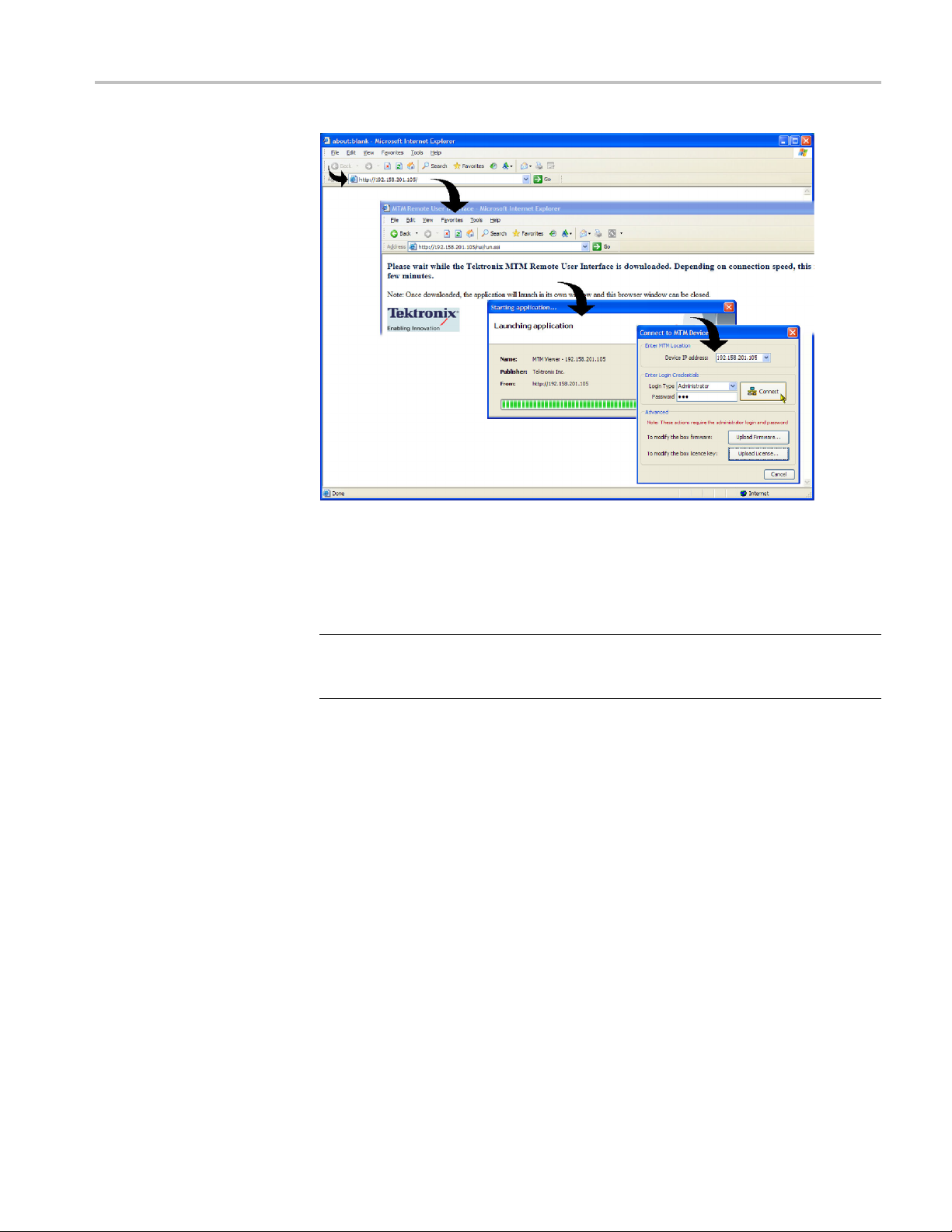
3. After the Java applet is downloaded, the Connect to MTM Device dialog box
is displayed. (See Figure 1.)
4 IPM4UP Upgrade Instructions

Software Option Upgrade
Figure 1: Logging on to IPM400A monitor
4. In the Connect to MTM Device dialog box, select Administrator from
the Login Type drop-down list, and then enter the password. The default
passwo
NOTE. You must log in to the monitor using the Administrator login type. The
User login type does not have sufficient permissions to perform software option
upgrades.
5. Click Connect to log on to the monitor and display the RUI window.
6. Click Device in the button bar of the RUI window to display the Device
Information view. (See Figure 2.)
7. Verify that the Network MAC Address shown in the Device Information view
matches the Unique ID number listed on the option key document that was
shipped with the upgrade kit.
8. Make a note of the software options that are currently enabled on the monitor.
NOTE. After you upgrade the monitor, you will verify the upgrade by checking
that the new option that you purchased has been enabled.
rd for Administrator login type is tek.
IPM4UP Upgrade Instructions 5

Software Option Upgrade
Figure 2: Device Information view
9. After you verify the MAC address and note the installed software options,
close the RUI window, repeat steps 2 through 4 to redisplay the Connect to
MTM Device dialog box, and then proceed to step 10.
NOTE.
to MTM Device dialog box that appears before the monitor RUI is launched.
Only advanced users should use the Connect to MTM Device dialog box that is
accessed from the Connect button in the monitor RUI toolbar.
10. In the Connect to MTM Device dialog box, click Upload License to open the
CAUTION. The option key string is case-sensitive and must be entered exactly as it
appears on the option key document, including any dashes.
11. In the Upload License dialog box, enter the new option key that was supplied
12. Click Yes to confirm the upload in the Upload License message box. (See
You should initiate the software options upgrade process from the Connect
Upload License dialog box. (See Figure 3.)
with this kit, and then click Upload.
Figure 4.)
6 IPM4UP Upgrade Instructions

Figure 3: Upload license dialog box
Software Option Upgrade
Figure 4: Upload license message box
13. Progress messages will be displayed in the Upload Lic ense dialog box as the
new option key is loaded into the monitor:
If the option key is accepted, the message "License upload ok" appears,
and then the monitor automatically reboots. The reboot process
ements the software options enabled by the new option key. The
impl
message "Reboot complete" appears after the monitor reboots.
he option key is rejected, the message "License upload error -
If t
invalid license" appears in the Upload License dialog box. (See page 8,
Troubleshooting.)
14. Click Close to close the Upload License dialog box, and then proceed to verify
the software options. (See page 8, Verifying the Software Option Upgrade.)
IPM4UP Upgrade Instructions 7

Software Option Upgrade
Troubleshooting
If the option key upload is rejected, the message “License upload error − invalid
license” appears in the Upload License dialog box. Use the following steps
to correct the problem:
Reenter the option key in the Upload License dialog box. The option key
string is case-sensitive and must be entered exactly as it appears on the option
key document, including any dashes.
Inspect the option key documentation that was supplied with the upgrade kit
and verify that you are applying the option key to the IPM400A DTV monitor
listed in
If you are upgrading a monitor that is connected to a network containing
more tha
monitor. Select Info in the Device view and verify that the MAC Address
of the monitor matches the Unique ID number listed on the option key
documentation supplied with the upgrade kit.
If the upgrade is still unsuccessful, contact Tektronix Technical Support, ensuring
that the following information is available:
the documents.
n one DTV monitor, ensure that the RUI is viewing the correct
Serial Number of the DTV monitor
MAC Address of the TS processor board
on key string that was supplied with the upgrade kit
Opti
Option key string that was previously assigned to the monitor (should be
ted on the label attached to the top cover of the monitor)
lis
Verifying the Software Option Upgrade
rform the following steps to verify the software option upgrade:
Pe
1. Display the Device Information view. Refer to steps 1 through 6 of the
revious procedure. (See page 4, Upgrading the Software .)
p
2. Verify that the new software option that you purchased with this upgrade is
now enabled. The option is listed on the option key documentation.
8 IPM4UP Upgrade Instructions

Figure 5: Device Information view
Software Option Upgrade
CAUTION. Be sure to apply the option key label from the Product Upgrade sticker.
When it is necessary after a repair, the Tektronix service center uses the option key
listed on the monitor label to reenable the software options for your monitor. If
youdon
cover of the monitor and your monitor is sent to Tektronix for repair, the monitor
might be returned to you without all of your software options enabled.
3. After you verify that the proper software options are enabled, a pply the
4. Apply the option-upgrade label from the Product Upgrade sticker to the top
ot apply the new option key label supplied with the upgrade kit to the top
option-key label from the Product Upgrade sticker that was supplied with
the upgrade kit to the top cover of the monitor, covering over the previous
option key listed on the monitor label.
cover of the monitor n ext to the options listed on the monitor label.
IPM4UP Upgrade Instructions 9
Hardware Option Upgrade
Hardware Opti
on Upgrade
Install the SFP Module
If you purcha
LX, SX, or ZX), perform the following steps to install and verify the SFP module.
Install the
Verify the SFP Module Upgrade (See page 11.)
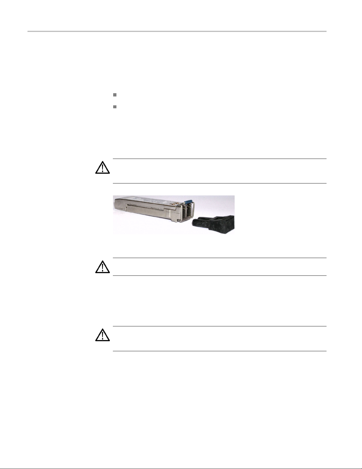
Perform the following steps to install the SFP module. (See Figure 6.)
WARNING.
Class 1 lasers as defined in the USA Federal Regulations CDRH 21 CFR 1040
and IEC/EN 60825/A2:2001.
sed an SFP module for your GbE interface card (IPM4UP options
SFP Module (See page 10.)
To prevent possible exposure to hazardous laser radiation, use only
Figure 6: SFP module and optical port plug
CAUTION. To prevent damage to the SFP module, remove power from the monitor
before removing or inserting the SFP module.
1. Remove power from the monitor.
2. Insert the SFP module into the rear-panel SFP 1000 connector. (See Figure 7.)
When fully inserted, the SFP module is latched in position.
WARNING. To prevent possible exposure to hazardous laser radiation, be sure to
install the optical port plug in the SFP module when no signal cable is connected
o the SFP module.
t
3. Proceed to Verify SFP Module Upgrade. (Seepage11.)
10 IPM4UP Upgrade Instructions
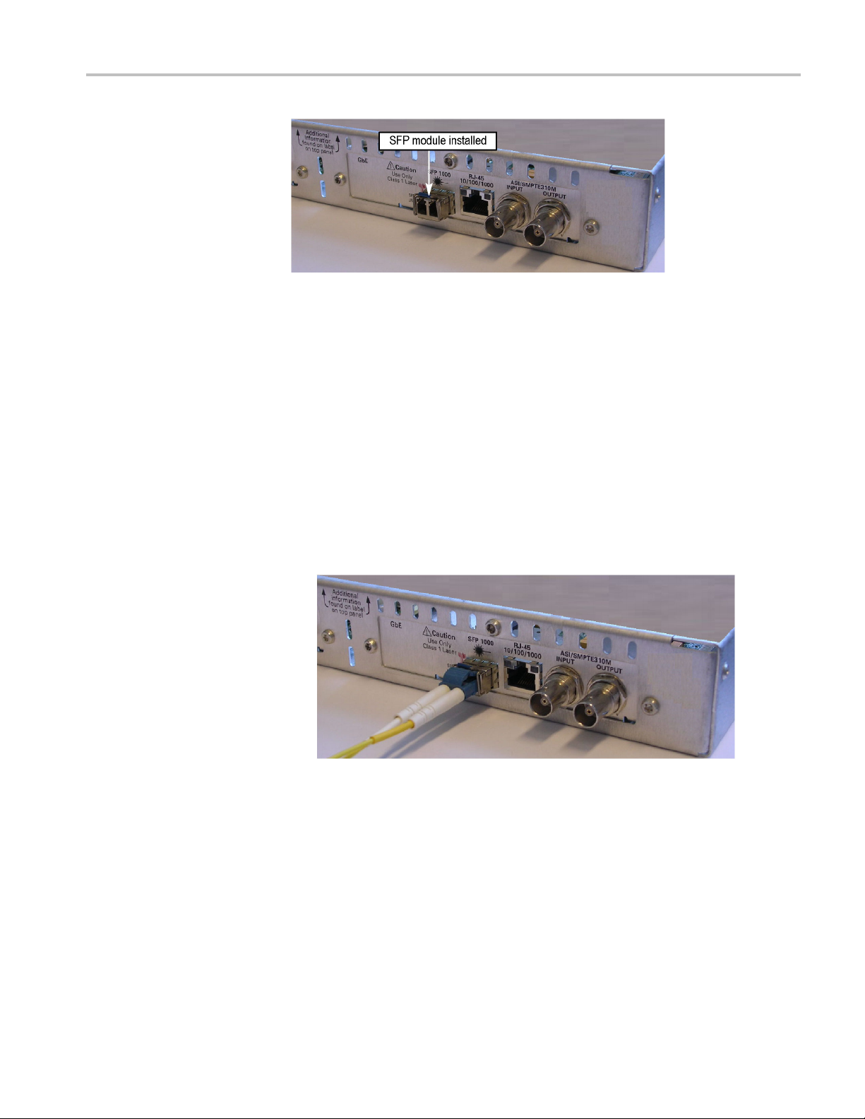
Figure 7: SFP module − installed
Ve rifying SFP Module Upgrade
To verify that the new SFP module you installed in the GbE interface card is
function
1. Connect an IP over optical signal, via the SFP module, to the GbE interface
ing correctly, perform the following procedure:
card:
Hardware Option Upgrade
a. Remove the optical port plug from the SFP module. (See Figure 6 on
page 10.)
b. Insert the optical cable into the SFP module. When fully inserted, the
connector is latched in position. (See Figure 8.)
cable
Figure 8: Optical cable connected to SFP module
2. Power on the monitor and wait for it to initialize. When the initialization
process is complete, the monitor beeps and the front-panel LEDs illuminate.
IPM4UP Upgrade Instructions 11

Hardware Option Upgrade
3. Using a PC that m
to the same Ethernet network as the monitor, perform the following steps
to open the RUI.
NOTE. This procedure uses Microsoft Internet Explorer to open the monitor
RUI. You can also access the RUI using the Tektronix Web Monitoring Systems
Manager (WebMSM ). The instructions for using WebMSM are located in the
WebMSM User
a. Launch Microsoft Internet Explorer.
b. In the address bar of the Web browser, enter the network identity
or IP address of the monitor, for example: http://TSMonitor01 or
http://111.222.333.444.
c. Press Enter. A Java applet is downloaded from the monitor and launched.
The file size is approximately 1.5 MB; the download time will depend
on the n
CAUTION. The Java applet w ill not run unless a temp directory is properly
configured on the PC. A temp directory is set up by default in the Windows XP
operating system; previous operating systems may require operator action.
eets the requirements for the RUI version and is connected
Manual (Tektronix part number 077-0116-xx).
etwork speed and traffic.
The Java applet will not run unless the Sun Java Virtual Machine is installed.
Type java -version at the command prompt to verify that it is installed and
that the version is 1.6.0_10 or greater. If it is not installed, you can download
the latest version from the Sun Web site, www.java.com.
If you have to update the Java version on the PC, you will need to restart this
procedure at step 2.
4. After the Java applet is downloaded, the Connect to MTM Device dialog box
is displayed. (See Figure 9.)
12 IPM4UP Upgrade Instructions
Hardware Option Upgrade
Figure 9: Logging on to an MTM400A monitor
5. In the Connect to MTM Device dialog box, select Administrator from
the Login Type drop-down list, and then enter the password. The default
passwo
NOTE. You must log in to the monitor using the Administrator login type. The
User login type does not have sufficient permissions to perform software option
upgrades.
6. Click Connect to log on to the monitor and display the RUI window.
7. Click the Interface toolbar icon to open the Interface dialog box.
8. In t
and then select Auto 1000(Optical) from the Select Speed drop-down list.
(See Figure 10.)
9. Close the Interface dialog box.
rd for Administrator login type is tek.
he Interface dialog box, select GbE from the Interfaces drop-down list,
IPM4UP Upgrade Instructions 13

Hardware Option Upgrade
Figure 10: Selecting the interface card speed in the Interface dialog box
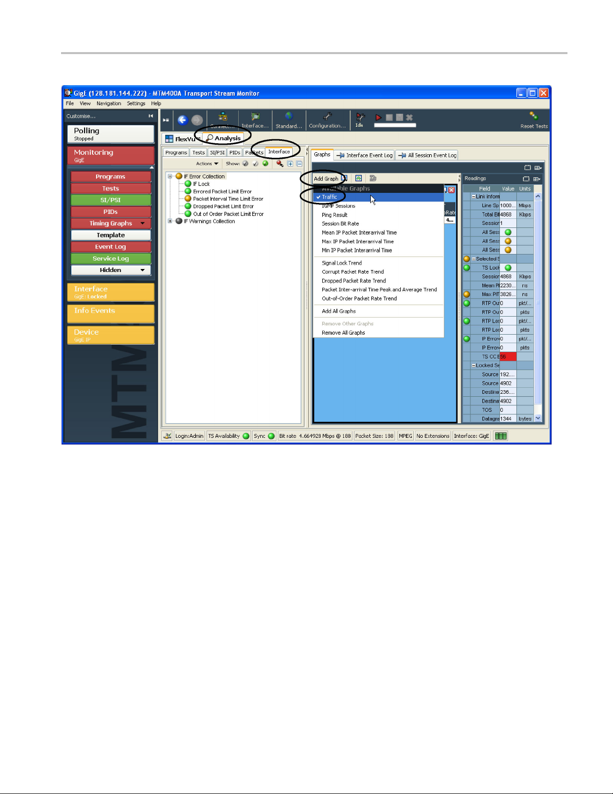
10. In the RUI window, click the Analysis tab, and then click the Interface tab.
11. Click
Add Graph on the Graphs tab, and then select Tr affic from t he
Available Graphs drop-down list. (See Figure 11.)
14 IPM4UP Upgrade Instructions
Hardware Option Upgrade
Figure
11: Selecting the Trafficgraph
12. Ve r i f
y that the monitor displays information about the program(s) contained
on the transport stream signal in the Traffic graph. (See Figure 12.) The
example transport stream in the following illustration contains one program.
IPM4UP Upgrade Instructions 15

Hardware Option Upgrade
Figure
12: Viewing the Trafficgraph
13. If the
End of Document
monitor displays information about the IP over optical signal in the
Traffic graph, then the SFP module is installed and operating properly. Apply
the Option Upgrade label from the Product Upgrade sticker that was supplied
with the upgrade kit to the top cover of the monitor next to the options listed
on the monitor label.
16 IPM4UP Upgrade Instructions
 Loading...