

Page 1
E
10225 B
ARNES CANYON RD., SUITE
(858) 558-8585 • F
A213 • S
AX
(858) 558-2552 • E-
LECTRONIC SYSTEMS, INC
AN DIEGO, CALIFORNIA
MAIL
: vektrex@vektrex.com
.
92121
Interchangeability
Using
IVI Class Interfaces
Revision 1.0
21 March 2003
Page 2

Interchangeability Using IVI Class Interfaces, Revision 1.0 21 March 2003
Table of Contents
1 INTRODUCTION ...................................................................................................... 3
1.1 IVI F
1.2 T
1.3 IVI D
1.4 IVI-C D
1.5 IVI-COM D
OUNDATION AND THE GOALS OF
ERMINOLOGY
RIVER ARCHITECTURE
RIVER ARCHITECTURE
...................................................................................................... 3
................................................................................... 4
RIVER ARCHITECTURE
IVI................................................................. 3
............................................................................... 5
.......................................................................... 5
2 IVI SHARED COMPONENTS................................................................................... 6
2.1 T
2.2 C
2.3 IVI
YPE LIBRARY
ONFIGURATION SERVER
SESSION FACTORY
DLLS............................................................................................. 6
.......................................................................................... 7
...................................................................................... 6
3 USING CLASS-COMPLIANT IVI-COM DRIVERS................................................... 9
3.1 IVI
3.2 E
3.2.1 Step1: Make the COM Object Available to the Project .........................................11
3.2.2 Step 2: Create an Instance of the IVI Session Factory Object..............................11
3.2.3 Step 3: The Form_Load Procedure......................................................................12
3.2.4 Step 4: Coding a Function....................................................................................13
3.2.5 Step 5: Tidying Up at the End of the Program ......................................................14
3.2.6 Step 6: Error Handling .........................................................................................14
3.3 E
3.3.1 Step 1: Creating the Project.................................................................................15
3.3.2 Step 2: Design a Dialog Box ................................................................................15
3.3.3 Step 3: Turn on COM...........................................................................................16
3.3.4 Step 4: Import the COM Components..................................................................17
3.3.5 Step 5: Create an Instance of the Driver Object...................................................18
3.3.6 Step 6: Using the Driver.......................................................................................20
3.3.7 Step 7: Error Handling .........................................................................................21
3.4 E
3.4.1 Step1: Make the COM Object Available to the Project .........................................22
3.4.2 Step 2: Declare Variables ....................................................................................22
3.4.3 Step 3: Instantiate and Initialize the Driver ...........................................................23
3.4.4 Step 4: Coding a Function....................................................................................24
3.4.5 Step 5: Tidying Up at the End of the Program ......................................................25
3.4.6 Step 6: Error Handling .........................................................................................25
3.5 V
3.5.1 Driver Instantiation and Initialization.....................................................................27
3.5.2 Fetch Waveform ..................................................................................................27
3.5.3 Error Handling......................................................................................................28
CONFIGURATION STORE ENTRIES
XAMPLE: DEVELOP A VISUAL BASIC CLIENT
XAMPLE: DEVELOPING A VISUAL
XAMPLE: DEVELOPING A VB
ISUAL BASIC SCRIPT
......................................................................................... 25
.NET C
..................................................................... 9
C++ C
LIENT
LIENT
........................................................ 10
..................................................... 14
.......................................................... 22
Copyright Vektrex
2
Page 3

Interchangeability Using IVI Class Interfaces, Revision 1.0 21 March 2003
1 Introduction
This white paper is provided by Vektrex to help end-users overcome the learning curve and
initial difficulties with using IVI drivers. The focus of this paper is to:
1. Provide a brief overview of IVI and the IVI architecture.
2. Provide examples of how to use interchangeable class interfaces from various client
environments.
Vektrex is a founding member of the IVI Foundation and is dedicated to providing the best
possible IVI driver end-user experience.
1.1 IVI Foundation and the Goals of IVI
The IVI Foundation is an open consortium of companies chartered with promoting
interchangeability of instrumentation to preserve test programs in the face of rapidly changing
technology. The IVI Foundation consists of end-user test engineers, instrument suppliers and
system integrators with many years of experience with test systems. By defining a standard
instrument driver model that enables engineers to swap instruments with minimal or no software
changes, the IVI Foundation members believe that significant savings in time and money will
result.
The goals of IVI are hardware interchangeability, quality, and Architectural Interoperability
These goals can be further broken down into:
1. Hardware Interchangeability
a. To simplify the task of replacing an instrument from a system with a similar
instrument
b.
To preserve test software when instruments become obsolete
c. To simplify test code reuse from design validation to production test
2. Quality
a. To improve driver quality
b. To establish guidelines for driver testing and verification
3. Architectural Interoperability
TM
a. To provide an architectural framework that allows users to easily integrate
software from multiple vendors
b. To provide standard access to driver capabilities such as initialization, range
checking and state caching
c. To simulate instruments and develop test system software when instruments are
not physically available
d. To provide consistent instrument control in popular programming environments
TM
.
1.2 Terminology
To understand the IVI architecture it is useful to review some of the terminology.
Copyright Vektrex
3
Page 4

Interchangeability Using IVI Class Interfaces, Revision 1.0 21 March 2003
• inherent capabilities – Capabilities that every driver must implement. These include
methods such as Initialize and Close and properties such as Description, Revision, and
Vendor.
• instrument class – A particular type of instrument (e.g., scope, DMM) that has a set of
behavior that is common amongst most instruments of that type. The IVI Foundation
has identified and documented this set of common behavior for various classes of
instruments such as scope, DMM, and power meter.
• base class capabilities – Capabilities that are common to most instruments in a class
(e.g., edge-triggered acquisition on a scope);
• class extension capabilities – Capabilities that represent more specialized features of
an instrument class (e.g., TV or width trigger on a scope).
• instrument specific capabilities – Capabilities that have not been standardized by the
IVI Foundation and are unique to an instrument.
• IVI custom specific drivers - IVI custom specific drivers support only inherent
capabilities and instrument specific capabilities.
• IVI class driver – A DLL that provides the class interface for IVI-C drivers.
• IVI class-compliant specific drivers - IVI class-compliant specific drivers contain
inherent capabilities, base class capabilities, as well as class extension capabilities that
the instrument supports. To achieve interchangeability, users program to an IVI class
interface available through an IVI class-compliant specific driver or an IVI class driver.
1.3 IVI Driver Architecture
The following diagram illustrates the generic IVI driver architecture. An IVI driver can present, to
the client test program, a class interface, an instrument specific interface, or both. If both
interfaces exist, a client test program can call the driver through the class or instrument specific
interface. To assure interchangeability, only the class interface should be used.
IVI drivers interact with IVI Shared Components such as the IVI Configuration Server and the IVI
Session Factory. Please refer to section 2.0 for more information on the IVI Shared
Components. IVI drivers communicate with the instrument through an I/O layer, typically VISA.
Copyright Vektrex
4
Page 5

Interchangeability Using IVI Class Interfaces, Revision 1.0 21 March 2003
The IVI Foundation defines two driver architectures. Drivers can be written using the IVI-C or
the IVI-COM architectures. A brief comparison of the two architectures is presented in the next
two sections. However, this paper is focused on the IVI-COM architecture.
1.4 IVI-C Driver Architecture
The diagram below shows the generic IVI driver architecture modified to show how IVI-C drivers
work. The modules inside the dashed box collectively represent the “IVI driver”. The IVI driver
in this example implements both a class and an instrument specific interface. To access the
instrument specific interface, the client program calls directly into the IVI-C Class-Compliant
Specific Driver. To access the class interface, the client calls into the IVI Class Driver that will
in-turn call into the IVI-C Class-Compliant Specific Driver. The IVI Engine is a separate module
that handles simulation and state management.
1.5 IVI-COM Driver Architecture
The diagram below shows the generic IVI driver architecture modified to show how IVI-COM
drivers work. The module inside the dashed box represents the “IVI driver”. The IVI driver in
this example implements both a class and an instrument specific interface. IVI-COM drivers are
different from IVI-C drivers in that both the class interface and the instrument specific interface
are encapsulated in one driver COM object. To client calls into either the class or instrument
specific interface as needed.
Copyright Vektrex
5
Page 6

Interchangeability Using IVI Class Interfaces, Revision 1.0 21 March 2003
2 IVI Shared Components
IVI Shared Components are software components owned and licensed by the IVI Foundation.
The shared components enforce the IVI driver architecture and simplify driver and client
application development. The most frequently used components by IVI-COM drivers are the
Type Library DLLs, the Configuration Server, and IVI Session Factory.
2.1 Type Library DLLs
A type library contains type information about objects. Developers create type libraries using the
Microsoft Interface Definition Language (MIDL) compiler. Type libraries contain information
about interfaces, structures, and enumerations and all their members. This information can be
obtained from the type libraries without actually referring to the object implementing these
features. This is important when developing COM clients because you usually don't know in
which directory - or computer - the implementation library resides. Early-bound COM clients use
type library information at compile-time to call methods directly.
The IVI Foundation distributes type library DLLs for all the instrument classes. The various
client environments can take advantage of the IVI class interfaces by referencing or importing
these DLLs. The IVI Shared Components Installer installs the DLLs.
2.2 Configuration Server
The IVI Configuration Server is the run-time module responsible for providing system database
services to IVI applications. Specifically, it provides system initialization and configuration
information. The Configuration Server consists of the configuration store XML file and a COM
object containing methods and properties to access the XML file.
The IVI Configuration Server is used by other IVI Shared Components including IVI Session
Factory. Since a typical system intermixes instruments and drivers from multiple vendors, the
system configuration service needs to be accessed in a vendor independent fashion. The IVI
Foundation provides the IVI Configuration Server because the IVI architecture requires a single
Configuration Server be installed on any system; a single shared configuration service
Copyright Vektrex
6
Page 7

Interchangeability Using IVI Class Interfaces, Revision 1.0 21 March 2003
implementation eliminates potential conflicts from divergent implementations. The IVI
Configuration Server consists of a single executable and one or more XML databases.
The
physical database(s) are collectively known as the Configuration Store. APIs are available to
read and write data to the configuration store file. Information stored in the Configuration Store
creates associations between:
• A logical name that refers to a particular driver/instrument combination (e.g.,
CompliantScope).
• A driver that communicates with an instrument. This is represented in the
configuration store by the driver’s progid in the form appname.objecttype, where
appname is the name of the application providing the object and objecttype is the
type or class of object (e.g., CompliantScope.CompliantScope). IVI-COM drivers do
not usually expose more than one object, so this repeated name will be common.
• A resource descriptor for the instrument (e.g., GPIB0::30::INSTR).
• Default settings for driver parameters like caching, range checking, etc.
• Alternate names for repeated capabilities (e.g., instead of using the supplied
ScopeChannel1, refer to the channel as CH1 or ClockFrequency).
Both the driver (in order to resolve a logical name to resource descriptor mapping, for example)
and the IVI Session Factory can access the Configuration Server. An excerpt from the
Configuration Server’s XML file is shown below. This section contains the VISA resource
descriptor (hardware asset) associated with the CompliantScope driver.
2.3 IVI Session Factory
The IVI Session Factory provides the client application a simple mechanism to instantiate IVICOM driver objects. The IVI Session Factory works with the Configuration Server to provide
interchangeability without modifying the client program source code. This is achieved by asking
the IVI Session Factory to create a driver instance using a logical name. The Configuration
Server uses the Configuration Store XML file to make the connection between the logical name
and a driver. The IVI Session Factory uses this information to create the driver. If another
instrument/driver is required, the Configuration Store XML file is changed by the driver user to
map the existing logical name to a new driver. No changes to the client application are required.
The following Visual Basic code fragment shows how a client can use the IVI Session Factory.
IviSessionFactory and IviScope are added to the project’s references. Note there are no
Copyright Vektrex
7
Page 8

Interchangeability Using IVI Class Interfaces, Revision 1.0 21 March 2003
references to a particular driver in the code. The link between the logical name
“CompliantScope” and the driver is made in the Configuration Store XML file.
Dim SessionFactory As New IviSessionFactory
Dim CompliantScope As IIviScope
Private Sub Form_Load()
Set myScope = myFactory.CreateDriver("CompliantScope")
myScope.Initialize "CompliantScope", True, True, "simulate = true"
…
The IVI Session Factory follows the well-known factory design pattern. The factory completely
abstracts the creation and initialization of the product (in this case the driver object) from the
client. This indirection enables the client to focus on its discrete role in the application without
concerning itself with the details of how the product is created. Thus, as the product
implementation changes over time, the client remains unchanged.
Copyright Vektrex
8
Page 9

Interchangeability Using IVI Class Interfaces, Revision 1.0 21 March 2003
3 Using Class-Compliant IVI-COM Drivers
A key benefit of IVI drivers is the ability to achieve instrument interchangeability by having client
programs use the IVI class interfaces. This section describes how to use a class-compliant IVICOM oscilloscope driver from the following environments: Visual Basic, Visual C++, VB .NET,
and Visual Basic Scripting. Each example provides the necessary steps to use the driver in that
particular environment. The same example is shown for each environment in order to compare
and contrast the environments. The examples consist of:
1. Client environment settings
a. This includes the steps necessary to include the appropriate dlls and type
libraries
2. Scope initialization
a. The scope is set to the following values:
i. Range: 5V Pk-Pk
ii. Offset: 0V
iii. Probe attenuation: 1
iv. Channel 1 is enabled for a measurement
v. Vertical DC coupling
vi. Acquisition type is set to normal
vii. Acquisition time period is 1 ms
viii. Acquisition minimum number of points is 1000
ix. Acquisition start time is 0
x. The trigger is on channel1
xi. The trigger is on a positive slope
xii. The trigger level is 0
3. A measurement is done using the FetchWaveform method
4. The results are displayed
5. Error handling is discussed
The examples assume a signal source provides a 1KHz sine wave with amplitude of 2.5 V. The
programming steps for the signal source are not discussed.
All the following examples use the generic IVI Scope class programming interfaces. In every
example, except scripting, the IVI Session Factory shared component instantiates the driver and
returns a reference to the scope class interface. The IVI Session Factory uses driver session
information from the Configuration Store to instantiate the actual driver object. The
Configuration Store contains all the necessary information to instantiate and initialize the driver.
Section 3.1 illustrates the entries in the Configuration Store.
3.1 IVI Configuration Store Entries
The figure below shows some of the entries in the Configuration Store that the examples use.
The ConfigurationStore.xml file is typically located in the …\program files\ivi\data folder. The file
populates when an IVI driver installs. Some of the entries to note are the hardware asset
description (which is set to GPIB0::13::INSTR) and the channel and measurement mappings.
As the file is currently populated, channels are referred to as Channel1 and Channel2 and
measurements are referred to as Measurement1 and Measurement2. If any of these
parameters need to be changed, it is possible to edit this file with an XML editor. For our
examples, we will use all the default values in the file.
Copyright Vektrex
9
Page 10

Interchangeability Using IVI Class Interfaces, Revision 1.0 21 March 2003
3.2 Example: Develop a Visual Basic Client
This section describes the steps required to access an IVI-COM class-compliant driver from
Visual Basic. The discussion centers on an IVI-COM class-compliant specific oscilloscope
driver.
Copyright Vektrex
10
Page 11

Interchangeability Using IVI Class Interfaces, Revision 1.0 21 March 2003
3.2.1 Step1: Make the COM Object Available to the Project
After creating a new project, select References from the Project Menu. A dialog similar to that
shown below will appear. This box contains a list of the registered COM objects on the
computer. Select the IviScope and IviSessionFactory type libraries and then click OK.
3.2.2 Step 2: Create an Instance of the IVI Session Factory Object
At the top of the Visual Basic Code window type in the two lines shown in the diagram below.
Visual Basic’s Intellisense will step you through the statements. The New keyword will create an
object of type IviSessionFactory. A variable of type IIviScope is also declared.
Copyright Vektrex
11
Page 12

Interchangeability Using IVI Class Interfaces, Revision 1.0 21 March 2003
3.2.3 Step 3: The Form_Load Procedure
When a Visual Basic program runs, the Form_Load procedure executes first, so this is an ideal
place to instantiate and call the driver’s Initialize function. The diagram below shows the code
that instantiates and initializes the driver. The example code shows the driver running in
simulation. If the actual hardware is available, “simulate=true” is not necessary. Note the literal
used to both create and initialize the driver is “CompliantScope.” The IVI Session Factory and
the initialize method use the Configuration Store to find the necessary information. Information
about instantiating the driver is retrieved from the Configuration Store by the IVI Session
Factory. Information about the hardware asset is retrieved from the Configuration Store by the
Initialize method.
Copyright Vektrex
12
Page 13

Interchangeability Using IVI Class Interfaces, Revision 1.0 21 March 2003
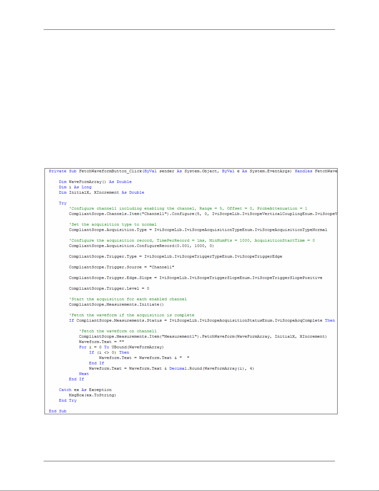
3.2.4 Step 4: Coding a Function
The diagram below shows a complete Visual Basic subroutine that fetches a waveform from the
scope. Intellisense helps the developer at each step, including listing options for any
enumerated types. This code assumes the Visual Basic form contains a button named
FetchWaveform for the user to press and a text box named Waveform that displays the return
value. This code also shows how the subroutine performs error handling – if an error occurs, the
subroutine calls an error handler.
Copyright Vektrex
13
Page 14

Interchangeability Using IVI Class Interfaces, Revision 1.0 21 March 2003
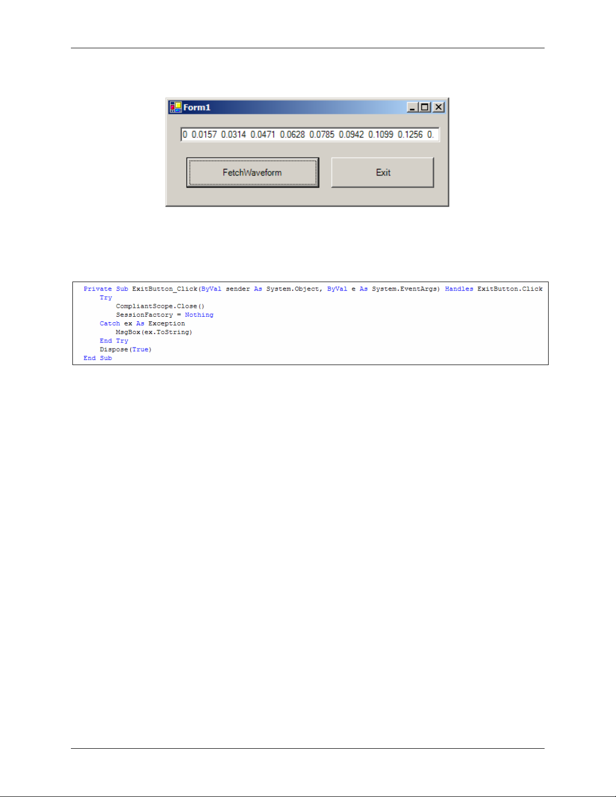
Clicking the FetchWaveform button produces the following sequence in the text box:
3.2.5 Step 5: Tidying Up at the End of the Program
The code snippet below runs when the user clicks Exit on the form. Exiting the program causes
the driver’s Close function to run, which releases the references and stops the program.
3.2.6 Step 6: Error Handling
If an error occurs inside the COM object, information about what happened is passed back to
Visual Basic inside an error object. This simple error handler causes a dialog box to appear with
the error number and description. When the user clears the dialog box, program execution
continues.
3.3 Example: Developing a Visual C++ Client
This section describes the steps required to access a class-compliant IVI-COM driver from a
Visual C++ MFC application. To illustrate this process we will build a simple project.
Copyright Vektrex
14
Page 15

Interchangeability Using IVI Class Interfaces, Revision 1.0 21 March 2003
3.3.1 Step 1: Creating the Project
Use Visual C++ to create a new MFC application (exe). A simple dialog-based program will
demonstrate the concepts.
3.3.2 Step 2: Design a Dialog Box
Design a dialog box with a button to fetch the waveform and an edit box to display the results.
Include an exit button to exit the program.
Copyright Vektrex
15
Page 16

Interchangeability Using IVI Class Interfaces, Revision 1.0 21 March 2003
3.3.3 Step 3: Turn on COM
Add a call to AfxOleInit in the CCompliantScopeCApp class’s InitInstance function, as shown
below.
Copyright Vektrex
16
Page 17

Interchangeability Using IVI Class Interfaces, Revision 1.0 21 March 2003
3.3.4 Step 4: Import the COM Components
Import the components using the #import command and the DLL names in the main header file
(CompliantScopeC.h, in this example). Note the IVI DLLs need no path information since they
are in locations known to C++, due to path information installed by the IVI Shared Components
installer.
Copyright Vektrex
17
Page 18

Interchangeability Using IVI Class Interfaces, Revision 1.0 21 March 2003
3.3.5 Step 5: Create an Instance of the Driver Object
The driver uses smart pointers to communicate with the instrument. These C++ classes perform
a similar function for the drivers as the CString class does for the handling of strings (hiding the
allocations, de-allocations, etc). Appropriate smart pointers are available to the project following
the #import statements of Step 4
to the default interface. For the IVI Session Factory object, that interface is IIviSessionFactory
and the smart pointer corresponding to that interface is IIviSessionFactoryPtr. For the scope
class-compliant interface, the smart pointer is IiviScopePtr. The developer should add member
variables to the CCompliantScopeCDlg class to hold the pointers, as shown below. The
CCompliantScopeCDlg.h file contains this class definition.
. When an IVI-COM object is instantiated, it returns a pointer
Copyright Vektrex
18
Page 19
Interchangeability Using IVI Class Interfaces, Revision 1.0 21 March 2003
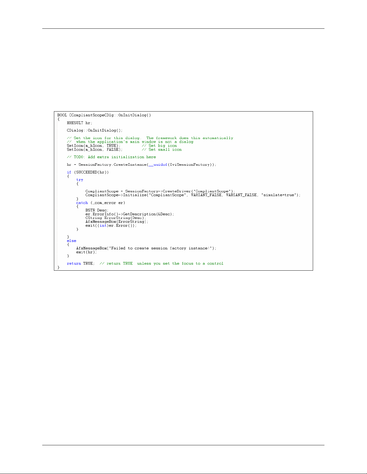
Since the Compliant Scope pointer provides access the driver object, the code to create and
initialize the instance can be inserted into the OnInitDialog function. The example code shows
the driver running in simulation. If the actual hardware is available, “simulate=true” is not
necessary. Note the literal used to both create and initialize the driver is “CompliantScope.” The
IVI Session Factory and the initialize method use the Configuration Store to find the necessary
information. Information about instantiating the driver is retrieved from the Configuration Store
by the IVI Session Factory. Information about the hardware asset is retrieved from the
Configuration Store by the Initialize method
Copyright Vektrex
19
Page 20

Interchangeability Using IVI Class Interfaces, Revision 1.0 21 March 2003
3.3.6 Step 6: Using the Driver
Our simple program needs to call two driver functions: one when the user clicks
FetchWaveform, and another when the user clicks Exit. The member variable m_Waveform is
associated with the dialog box’s edit control. The following figure displays the code for the
FetchWaveform button.
Copyright Vektrex
20
Page 21

Interchangeability Using IVI Class Interfaces, Revision 1.0 21 March 2003
The following figure displays the code for the Exit button.
Intellisense provides the developer real-time driver help as they type the code. Upon clicking
FetchWaveform, the following is displayed:
3.3.7 Step 7: Error Handling
This example illustrates standard C++ error handling using try/catch blocks. If an exception
occurs in the driver, the driver throws an exception, and standard COM error handling functions
can interrogate the IErrorInfo object.
Copyright Vektrex
21
Page 22
Interchangeability Using IVI Class Interfaces, Revision 1.0 21 March 2003
3.4 Example: Developing a VB .NET Client
This example describes the steps required to access an IVI-COM class-compliant driver from
VB .NET. The discussion centers on an IVI-COM class-compliant specific oscilloscope driver.
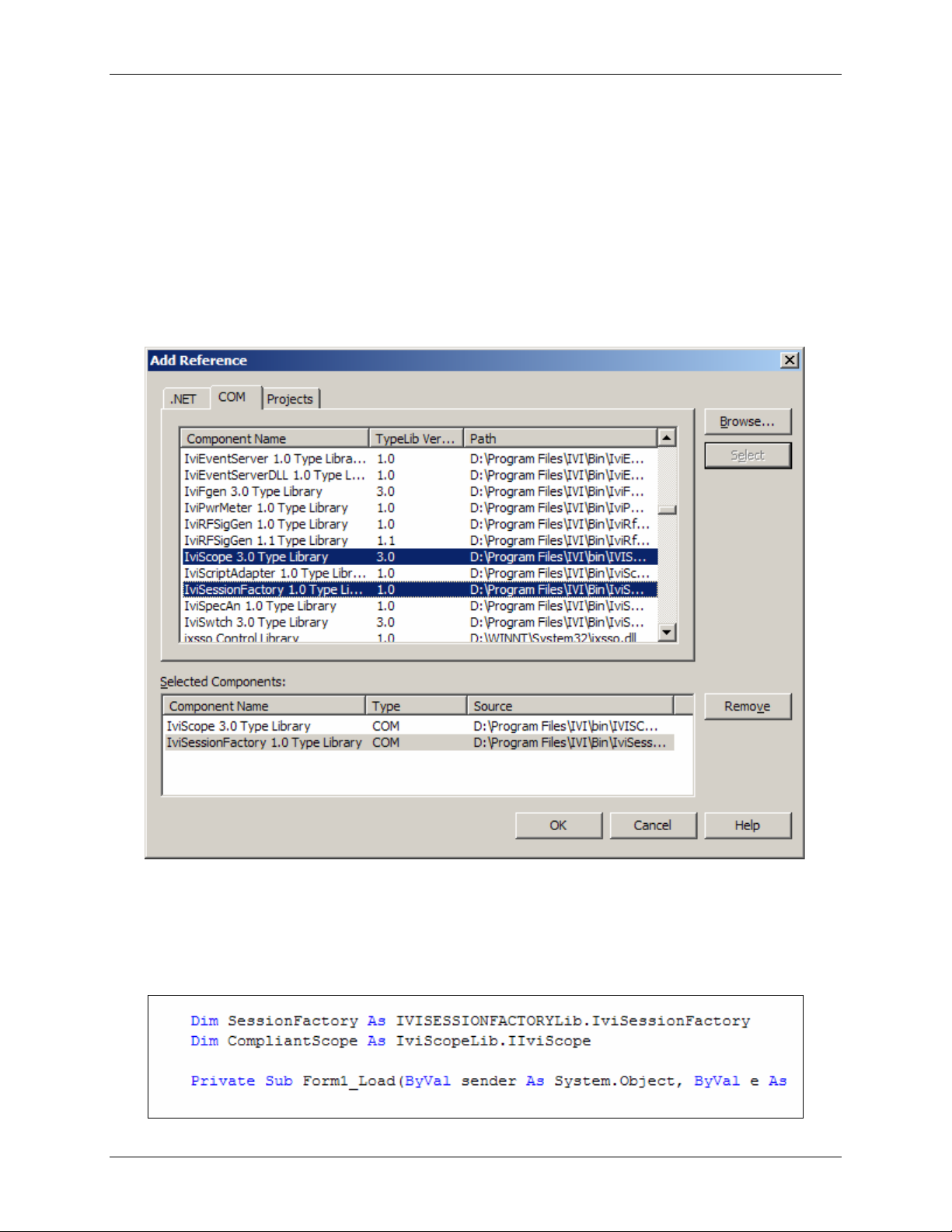
3.4.1 Step1: Make the COM Object Available to the Project
After creating a new project, select References from the Project Menu. A dialog similar to that
shown below will appear. Click the COM tab. The ensuing dialog lists the registered COM
objects on the computer. Select the IviScope and IviSessionFactory components and click
OK.
3.4.2 Step 2: Declare Variables
At the top of the Visual Basic Code window type in the two lines shown in the diagram below.
Visual Basic’s Intellisense will step you through the statements. Declare variables of type
IviSessionFactory and IIviScope.
Copyright Vektrex
22
Page 23
Interchangeability Using IVI Class Interfaces, Revision 1.0 21 March 2003
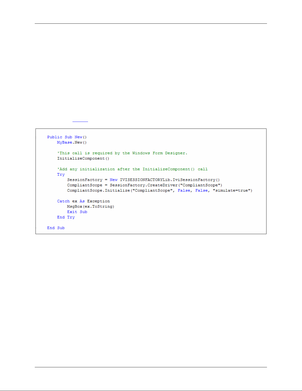
3.4.3 Step 3: Instantiate and Initialize the Driver
When VB .NET initializes an application, it calls the New subroutine. This is the appropriate
location to add code that instantiates and initializes the driver.
The example code (below) shows the driver running in simulation. If the actual hardware is
available, “simulate=true” is not necessary. Note the literal used to both create and initialize the
driver is “CompliantScope”. The IVI Session Factory and the initialize method use the
Configuration Store to find the necessary information. Information about instantiating the driver
is retrieved from the Configuration Store by the IVI Session Factory. Information about the
hardware asset is retrieved from the Configuration Store by the Initialize method
The error handling in this subroutine is different from the type used in the Visual Basic example.
Please refer to Step 6
for more information on error handling.
Copyright Vektrex
23
Page 24
Interchangeability Using IVI Class Interfaces, Revision 1.0 21 March 2003
3.4.4 Step 4: Coding a Function
The diagram below shows a complete Visual Basic .NET subroutine that fetches a waveform
from the scope. Intellisense will help the developer code the driver by listing options for any
enumerated types. This code assumes the Visual Basic .NET form contains a FetchWaveform
button and a text box named Waveform to display the return value. This code also shows how
the subroutine performs error handling. The error handling is similar to C++ error handling with
try/catch blocks. VB .NET supports both Visual Basic 6.0 type error handling (i.e., “on error goto
…”) and C++ type error handling.
VB .NET requires full namespace resolution. This can be seen in how enumerations are treated
– an enumeration requires a namespace, enumeration name, and enumeration value. An
example of this is:
IviScopeLib.IviScopeTriggerSlopeEnum.IviScopeTriggerSlopePositive
Copyright Vektrex
24
Page 25
Interchangeability Using IVI Class Interfaces, Revision 1.0 21 March 2003
When the user clicks FetchWaveform the following is displayed in the text box:
3.4.5 Step 5: Tidying Up at the End of the Program
When the user clicks Exit, the driver’s Close function executes and the references are
released.
3.4.6 Step 6: Error Handling
This example uses C++ type error handling; specifically, it uses try/catch blocks. The error
handling code in the various subroutines catch the error and display a message box with the
actual error string.
3.5 Visual Basic Script
IVI-COM drivers developed with Vektrex’s VIVID Driver Development toolkit support Visual
Basic Script as a client environment. The actual lines of VB Scirpt code look very similar to
Visual Basic. However, there are some differences:
1. VB Script is “late-binding,” so no compile time error checking is done and there is no
concept of Intellisense
2. VB Script has limited user interface capabilities
3. Enumerations are not directly supported
4. Error handling is more limited in VB Script than in Visual Basic
5. All data types are variants
Copyright Vektrex
25
Page 26

Interchangeability Using IVI Class Interfaces, Revision 1.0 21 March 2003
Armed with this knowledge it is very straightforward to write client applications in VB Script. The
following script implements the same fetch waveform as the previous examples. Since there are
no sophisticated user interfaces, the script just runs once, executing the fetch waveform
function.
The example code shows the driver running in simulation. If the actual hardware is available,
“simulate=true” is not necessary. Note the literal used to initialize the driver is
“CompliantScope.” While initializing the driver, information about the hardware asset is retrieved
from the Configuration Store.
Copyright Vektrex
26
Page 27

Interchangeability Using IVI Class Interfaces, Revision 1.0 21 March 2003
3.5.1 Driver Instantiation and Initialization
There is no compile-time knowledge in VB Script, so the IVI Session Factory is not entirely
necessary. VB Script requires the class and server name of the object to be created. Since
these values can be parameterized, the IVI Session Factory is not necessary. The following
script code instantiates and initializes the compliant scope driver.
3.5.2 Fetch Waveform
The script code that actually sets up the instrument and fetches a result looks similar to the
Visual Basic code.
The one difference is that a message box displays the retrieved values.
Copyright Vektrex
27
Page 28

Interchangeability Using IVI Class Interfaces, Revision 1.0 21 March 2003
3.5.3 Error Handling
VB Script supports a very simple form of VB error handling. The VB Script error handling (“on
error resume next”) just executes the next line in the script after the error. VB Script does
contain error functions (Err.Number) that can be checked after each call to determine whether
an error occurred.
Copyright Vektrex
28
 Loading...