

Page 1

Instructions
040-1480-04
Enhanced Monitor Upgrade Kit
VX1410 IntelliFrame
070-9471-03
Warning
The servicing instructions are for use by qualified
personnel only. To avoid personal injury, do not
perform any servicing unless you are qualified to
do so. Refer to all Safety Summaries prior to
performing service.
Page 2

Copyright E T ektronix, Inc. 1995. All rights reserved.
T ektronix products are covered by U.S. and foreign patents, issued and pending. Information in this publication
supercedes that in all previously published material. Specifications and price change privileges reserved.
Printed in the U.S.A.
T ektronix, Inc., P.O. Box 1000, Wilsonville, OR 97070–1000
TEKTRONIX and TEK are registered trademarks of T ektronix, Inc.
IntelliFrame is a trademark of T ektronix, Inc.
Page 3

Kit Description
This kit includes parts and instructions to upgrade the Standard Monitor board
with an Enhanced Monitor Board (Option 1M), to replace the Top Extrusion on a
VX1410 IntelliFrame mainframe, and to add an air baffle to the mainframe.
Instruments
There are no instrument serial numbers associated with this kit for theVX1410
IntelliFrame mainframe.
Minimum Tool and Equipment List
Tools and Equipment Needed
Torx screwdriver with a T-20 tip and a magnetic T -10 amd T-15 tip
Small flat blade screwdriver
Phillips screwdriver with a #2 tip
IBM Personal Computer (or equivalent) with Windows 3.1 (or higher) and an RS-232 port
RS–232 NULL modem cable (connector compatible with the PC and a DB9 female connector)
Kit Parts List
Quantity Part Number Description
1 ea 671-3218-02 Enhanced Monitor Bd
1 ea –––––––––– Top Extrusion Assembly
6 ea 213-0882-00 6-32, T-15, thread tapping screws
1 ea 378-2079-00 Air baffle
1 ea 070-9019-XX VX1410 IntelliFrame Instruction Manual
1 ea 070-9471-XX Kit instructions
1 ea 063-2267-01 Software; Plug and Play: V4.0
VX1410 IntelliFrame Enhanced Monitor Upgrade Kit
1
Page 4

Kit Description
Service Safety Summary
WARNING. The servicing instructions are for use by qualified personnel only. To
avoid personal injury, do not perform any servicing unless you are qualified to
do so. Refer to to the General Safety Summary in the VX1410 IntelliFrame
Instruction Manual before performing any service.
Do Not Service Alone
Avoid Exposed Circuitry
Use Care When Servicing
With Power On
Do not perform internal service on this product unless another person capable of
rendering first aid and resuscitation is present.
To avoid injury, remove jewelry such as rings, watches, and other metallic
objects. Do not touch exposed connections and components when power is
present.
Dangerous voltages or currents may exist in this product. Disconnect power,
remove battery (if applicable), and disconnect test leads before removing
protective panels, soldering, or replacing components.
2
VX1410 IntelliFrame Enhanced Monitor Upgrade Kit
Page 5

Installation Instructions
These instructions assume a certain familiarity with the instrument. If you need
further details, refer to the VX1410 IntelliFrame Instruction Manual. For
assistance to install this kit, please call your nearest Tektronix, Inc., Service
Center or Tektronix Factory Service.
CAUTION. Many components within this instrument are extremely susceptible to
static-discharge damage. Service the instrument only in a static-free environment. Observe standard handling precautions for static-sensitive devices while
installing this kit. Always wear a grounded wrist and foot strap while installing
this kit.
Installing the Enhanced Monitor Board (Option 1M)
Before you install the Enhanced Monitor Board, you need to remove the fan
assembly and the Standard Monitor board.
Remove Fan Assembly
To remove the fan assembly, refer to Figures 1 and 2 and follow these steps:
1. Power down the instrument and disconnect the power cord.
2. Disconnect the Passive Monitor cable, if used. The Passive Monitor
connector is the 25 pin D-connector on the rear of the mainframe.
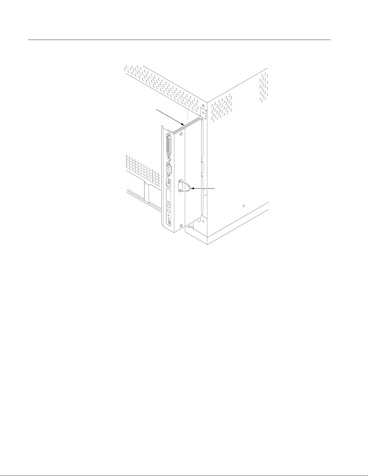
3. From the rear of the mainframe, use a Torx with a T-10 driver to remove the
four 8-32 screws (refer to Figure 1 for the screw locations).
4. Use a Torx with a T-20 driver to remove the 8-32 Safety Ground screw and
the Chassis Ground screw (if installed).
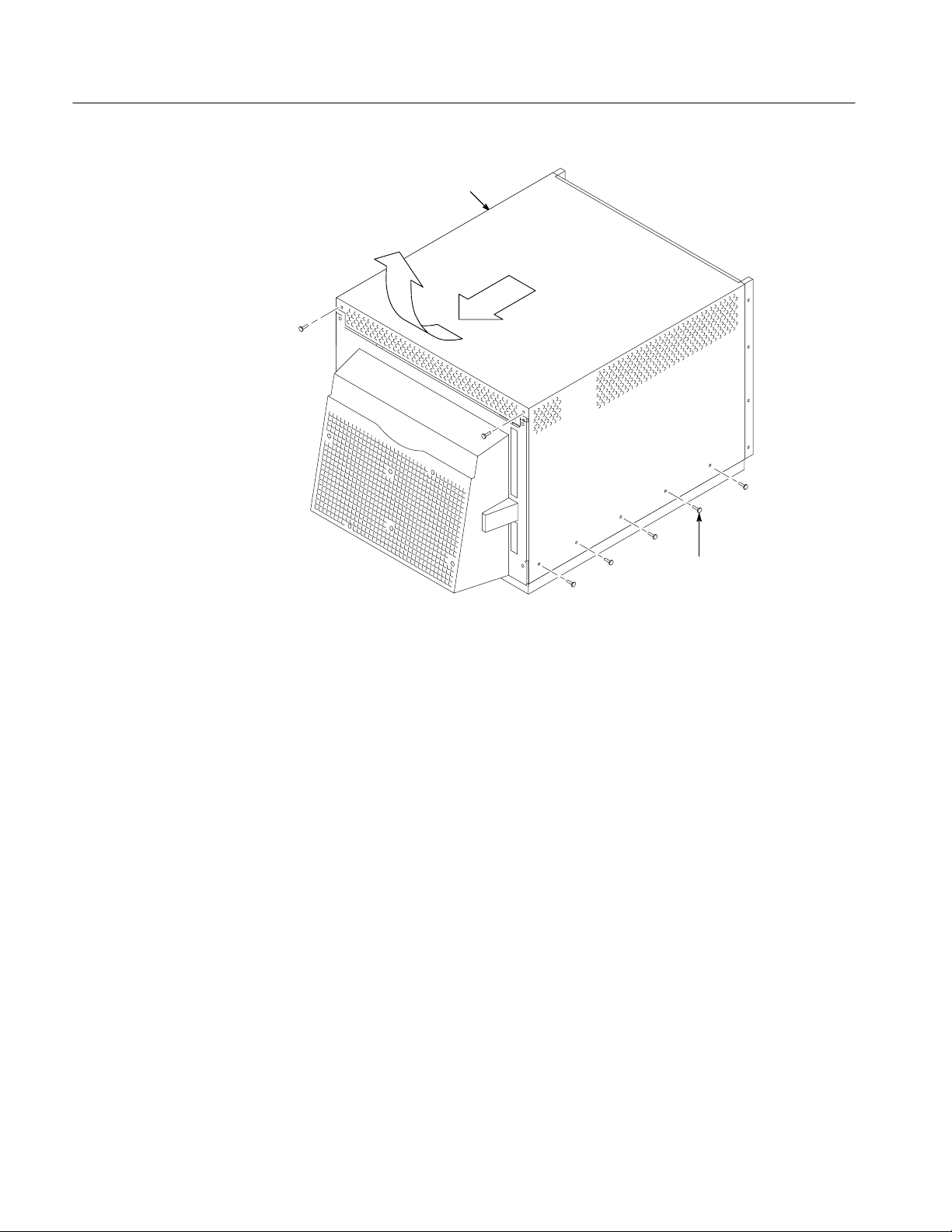
5. Gently pivot the fan assembly outward from the mainframe far enough to
access the fan cables on the right side of the mainframe.
6. Unplug the fan cables and set the fan assembly aside on a clean working
surface.
VX1410 IntelliFrame Enhanced Monitor Upgrade Kit
3
Page 6

Installation Instructions
8-32 Screw
Chassis Ground
Connection
Safety Ground
Screw
8-32 Screw
8-32 Screw
8-32 Screw
Figure 1: Location of Fan Assembly and Ground Screw on the Rear of Mainframe
Power Supply
8-32
Screws (5)
Ledge
Figure 2: Removing the Fan Assembly
Fan Cables
Fan Assembly
4
VX1410 IntelliFrame Enhanced Monitor Upgrade Kit
Page 7

Installation Instructions
Remove Standard Monitor
Board
To remove the Standard Monitor board, refer to Figure 3 and follow these steps:
1. Grasp and pull the cable tie loop until the monitor board comes loose from
the Backplane board.
2. Slide the board out of the mainframe.
Monitor Board
Cable Tie Loop
Figure 3: Removing the Standard Monitor Board
Install Enhanced Monitor
Board (Option 1M)
VX1410 IntelliFrame Enhanced Monitor Upgrade Kit
To install the Enhanced Monitor board, refer to Figure 4 and follow these steps:
1. Slide the metal shield part of the Enhanced Monitor board into the right side
of the mainframe where you just removed the Standard Monitor board.
2. Push in the Enhanced Monitor board until it is completely seated in the
Backplane board.
3. Push the cable tie loop inside the mainframe so the fan assembly will not
pinch the cable tie.
5
Page 8
Installation Instructions
Enhanced Monitor
Board
Cable Tie Loop
Reinstall Fan Assembly
Figure 4: Installing the Enhanced Monitor Board
To reinstall the fan assembly, refer to Figures 1 and 2, and follow these steps:
1. Line up the channel on the lower edge of the fan assembly with the ledge on
the mainframe and push the channel onto the ledge.
2. Line up the square cutout areas on the channel with the corresponding
uprights on the mainframe. Hold the fan assembly in this position, connected
at the bottom (ledge in the channel) and open enough at the top to allow
room for your hands.
3. Match the labels on the fan cables to their respective connectors on the rear
of the mainframe and plug them in.
4. Close the fan assembly to the mainframe, being careful not to pinch the fan
cables between the two.
5. Use a Torx with a T-10 driver to install the four 8-32 screws (refer to Figure
1 for the screw locations).
6. Use a Torx with a T-20 driver to install the 8-32 Safety Ground screw, and
the Chassis Ground screw (if used).
6
VX1410 IntelliFrame Enhanced Monitor Upgrade Kit
Page 9

If you are going to install the Front Panel Display, continue with the next
procedures.
If you are not going to install the Front Panel Display, you still need to perform
the following operations:
H Remove the top cover
H Move the Temperature Sense Board
H Calibrate the Enhanced Monitor (calibration procedure)
H Reinstall the top cover and add the air baffle
Replacing the Top Extrusion
Before you replace the Top Extrusion, you need to remove the top cover, remove
the upper card guides, and remove the Top Extrusion currently installed. After
you have replaced the new Top Extrusion, you need to move the Temperature
Sensing circuit board toward the front of the mainframe.
Installation Instructions
Remove Top Cover
To remove the top cover, refer to Figure 5 and follow these steps:
1. If the VX1410 IntelliFrame is mounted in a rack, remove it from the rack.
a. Use a Torx with a T-20 tip to remove the ten 8-32 screws that hold the
rack slides to the top cover of the mainframe.
b. Use a Torx with a T-10 driver to remove the other two 8-32 screws
holding the top cover to the mainframe.
2. If the mainframe is not mounted in a rack, use a T-10 Torx drive screwdriver
to remove the twelve 8-32 screws holding the top cover to the mainframe.
3. Slide the top cover back an inch and lift it off the mainframe.
VX1410 IntelliFrame Enhanced Monitor Upgrade Kit
7
Page 10
Installation Instructions
Top Cover
Remove Upper Card
Guides
8-32 Screws (12)
Figure 5: Removing the Top Cover and Top Extrusion
Before you can install the new Top Extrusion, you need to remove the upper card
guides. The card guides at the top and bottom of the mainframe are very similar.
The main difference is that the bottom guides (IntelliGuides) include the
spring-loaded shutters. The procedure for removing both guides is identical.
To remove the upper card guides, refer to Figure 6 and follow these steps:
1. Use a small flat blade screw driver to pry down the tab of the card guide at
the front of the mainframe being careful not to damage the card guide or the
mainframe.
2. Gently pull the card guide forward until it pops out of place.
3. Remove the card guide and all other upper card guides.
8
VX1410 IntelliFrame Enhanced Monitor Upgrade Kit
Page 11

Gently pull the card guide
forward until it pops out of place.
Installation Instructions
Figure 6: Removing the Top Card Guides
Remove Top Extrusion
To remove the Top Extrusion, refer to Figure 7 and follow these steps:
1. Clip the cable tie holding the On/Standby Switch cable in place.
2. Disconnect the On/Standby Switch cable from the Backplane board.
NOTE. Remember which connector you are disconnecting the On/Standby Switch
cable from, J22 (normally) or J23. You must reconnect the cable to the same
connector after the new Top Extrusion is installed.
3. Place the mainframe on its side.
NOTE. You need to use a Torx with a magnetic tip to remove the screws holding
the Top Extrusion to the mainframe. If you do not use a magnetic tip, the screws
might fall into the mainframe.
VX1410 IntelliFrame Enhanced Monitor Upgrade Kit
9
Page 12
Installation Instructions
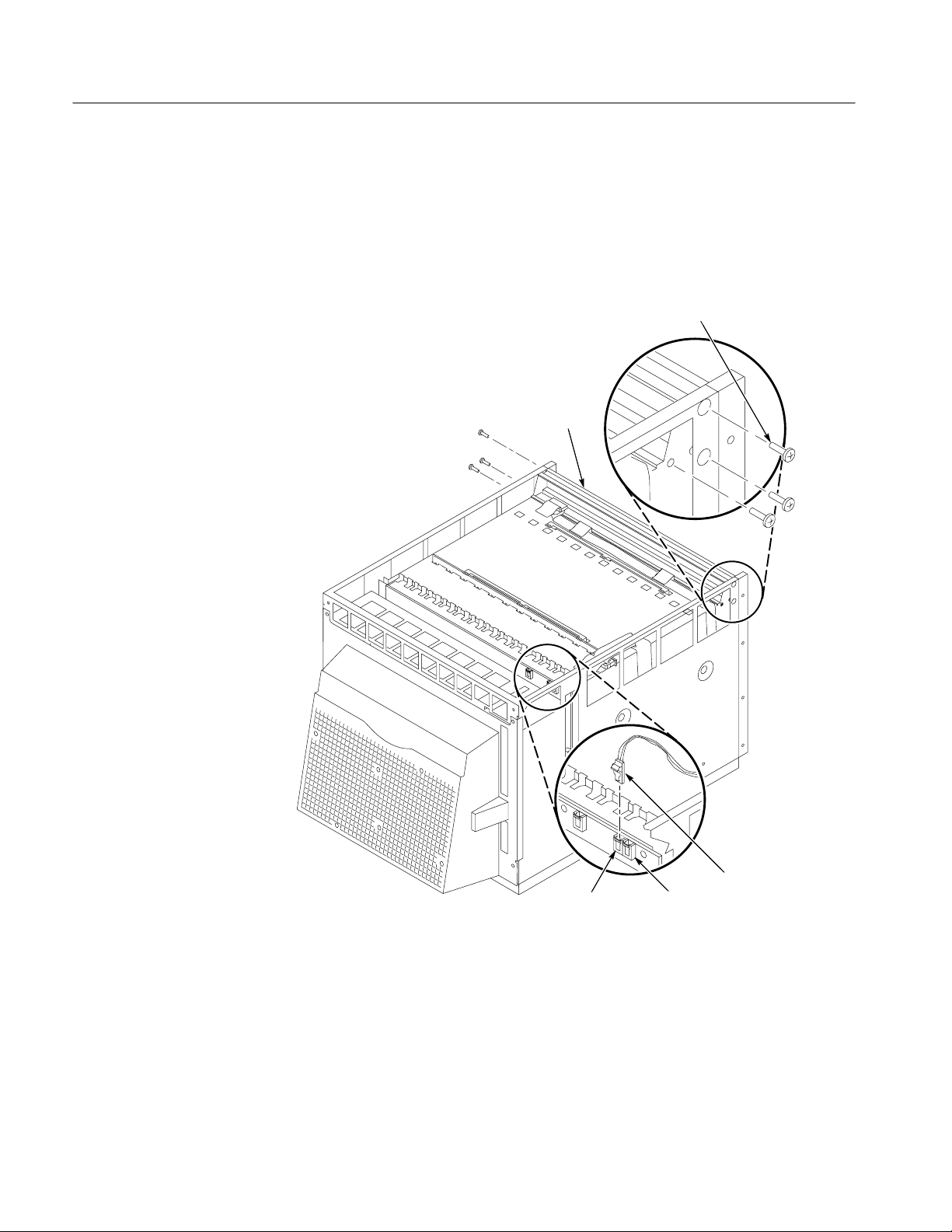
4. Use a Torx with a magnetic T-15 driver to remove the six 6-32 screws
holding the Top Extrusion to the mainframe.
5. Discard the screws.
6. Carefully remove the extrusion without scratching the paint.
Remove 6-32 Screws (6)
Extrusion
Install New Top Extrusion
10
Disconnect the On/Standby
J23J22
Switch Cable
Figure 7: Removing the Top Extrusion
To install the new Top Extrusion, refer to Figure 8 and follow these steps:
1. Place the new Top Extrusion in position in the mainframe; line up the screw
holes on the Top Extrusion with the screw holes on the mainframe.
VX1410 IntelliFrame Enhanced Monitor Upgrade Kit
Page 13

Installation Instructions
2. Use a Torx with a magnetic T-15 driver to install the six 6-32 screws
(supplied with this kit) that hold the Top Extrusion in the mainframe.
3. Line up the pin 1 indicator on the ribbon cable (the red strip) in the front of
the mainframe with the pin 1 indicator on the connector (the grey arrow) on
the Monitor Display board. Connect the ribbon cable to the connector.
4. Reconnect the On/Standby Switch cable to the Backplane board. Be sure to
connect the cable to the same connector you removed it from, J22 or J23.
Refer to the VX1410 IntelliFrame Instruction Manual for a description of
J22 and J23.
6-32 Screws (6)
Pin 1
Reinstall the Upper Card
Guides
New Extrusion
Display
Assembly
Figure 8: Installing the New Top Extrusion
To reinstall the upper card guides, refer to Figure 9. Slide the card guide toward
the rear of the mainframe and allow the front of the card guide to snap into place.
VX1410 IntelliFrame Enhanced Monitor Upgrade Kit
11
Page 14

Installation Instructions
Slide the card guides toward the rear of
the mainframe and allow the front of the
card guide to snap into place.
Figure 9: Reinstalling the Top Card Guides
Move the Temperature
Sense Board
To move the Temperature Sense board, refer to Figure 10 and follow these steps:
1. Disconnect the Temperature Sense board cable from the Temperature Sense
board.
2. Use a small flat blade screw driver to gently pry up each retainer tab holding
the Temperature Sense circuit board in place.
3. Lift the board out of the holes at the top of the mainframe being careful not
to damage any components on the board.
4. Move the board to the front of the mainframe where the other Temperature
Sense board retainer is located. When placing the board in position, be
careful not to damage any components.
5. Use a small flat blade screwdriver to gently pry up each retainer tab, push the
edge of the board under the tabs, and press the board back completely under
the tabs.
12
VX1410 IntelliFrame Enhanced Monitor Upgrade Kit
Page 15

Figure 10: Moving the Temperature Sense Board
Installation Instructions
Retainer
Temperature
Sense Board
Calibration Procedure
6. Line up the pin 1 indicator on the Temperature Sense board cable with pin 1
on the connector on the Temperature Sense board. Connect the cable to the
connector. Figure 11 shows the location of pin 1 on the connector.
Pin 1
Figure 11: Pin 1 Location on the Temperature Sense Board Connector
Before you reinstall the top cover of the mainframe, you need to calibrate the
Enhanced Monitor Card. To calibrate the Enhanced Monitor Card, you need the
following items:
H An IBM Personal Computer (or equivalent) with Windows 3.1 (or higher)
and an RS-232 port
H An RS-232 NULL modem cable with one compatible connector for the PC
and a DB9 female connector for the VX1410 IntelliFrame
VX1410 IntelliFrame Enhanced Monitor Upgrade Kit
13
Page 16

Installation Instructions
To calibrate the Enhanced Monitor Card, follow these steps:
1. Power on the VX1410 IntelliFrame mainframe. Wait for at least five minutes
for the mainframe to warm up.
2. While waiting for the mainframe to warm up, start up Microsoft Windows on
the PC and double click on the Microsoft Terminal progam icon. The
Terminal program is initially located in the Accessories folder.
3. When the mainframe is warmed up, set the FAN SPEED switch to VAR and
check that the T readout values are in the 0
° C 5° C range. To display the
T readout values, press the NEXT or PREV buttons and scroll through the
status messages.
If the T readout values are outside the acceptable range, check the
orientation of the Temperature Sense board cable.
4. Connect the RS-232 NULL modem cable between the COM port on the PC
and the RS-232 port on the rear panel of the mainframe.
5. In the Terminal program window, select the %##*$!)!%$( command
from the Settings menu. In the dialog box, select the appropriate COM port
and set it up as follows:
* )
) !)(
)%& !)(
'!)- %$
"%+ %$)'%" %$%
6. Click on OK.
7. In the Terminal program, enter:
.
The CAL? command returns a 0 to indicate that there were no errors.
8. To identify the Enhanced Monitor as part of the mainframe, you need to
enter the serial number of the mainframe into the NVRAM. Look on the rear
of the mainframe and note the serial number that starts with a B.
9. In the Terminal program, enter:
,,,,,,
The Bxxxxxx represents the serial number located on the rear of the
mainframe.
14
10. Press the NEXT or PREV buttons to scroll through the status messages and
check that the T readout values are in the 0
° C 1° C range for all slots.
VX1410 IntelliFrame Enhanced Monitor Upgrade Kit
Page 17
11. Power off the mainframe and reinstall the top cover.
Reinstall Top Cover and Add the Air Baffle
To reinstall the top cover and add the air baffle, refer to Figure 5, and follow
these steps:
1. Place the top cover on the mainframe about an inch from being all the way
forward.
2. Lift up the back of the top cover slightly and slide the front top edge into the
recessed area along the Top Extrusion.
3. If the mainframe is not mounted in a rack, use a Torx with a T-10 tip to
reinstall the ten 8-32 screws holding the top cover to the mainframe.
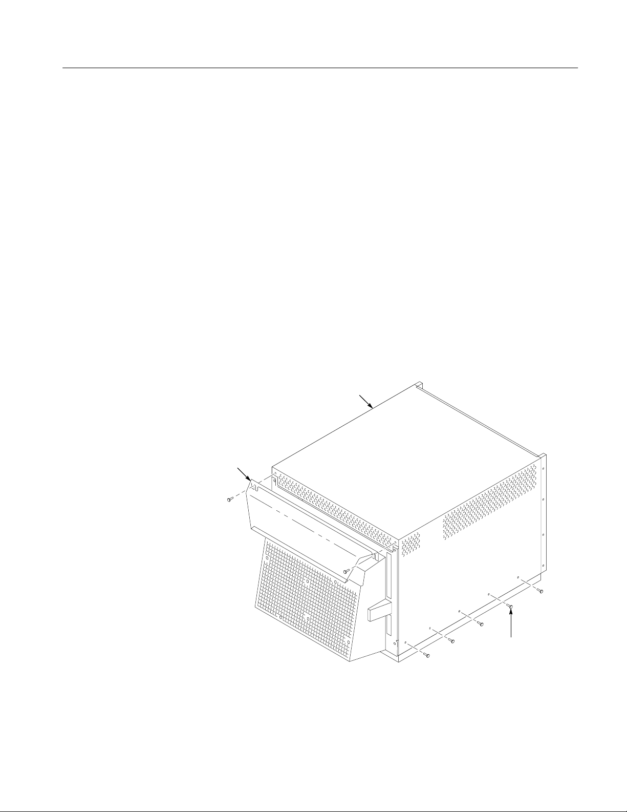
4. To add the air baffle, refer to Figure 12, and use a
reinstall the two 8-32 screws holding the air baffle and top cover to the
mainframe.
Installation Instructions
3
inch Allen wrench to
32
Air Baffle
Top Cover
8-32 Screws (12)
Figure 12: Reinstalling the Top Cover and Adding the Air Baffle
5. Reconnect the Passive Monitor cable, if used.
VX1410 IntelliFrame Enhanced Monitor Upgrade Kit
15
Page 18

Installation Instructions
6. If the mainframe was mounted in a rack, follow these steps:
a. Use a Torx with a T-20 tip to reinstall the ten 8-32 screws that hold the
rack slides and top cover to the mainframe.
b. To add the air baffle, refer to Figure 12, and use a T-10 Torx drive to
reinstall the two 8-32 screws holding the air baffle and top cover to the
mainframe.
c. Place the mainframe back in the rack.
d. Reconnect the Passive Monitor cable, if used.
7. Install the Slot 0 module, and slide the top nut rails to the left. Reinstall the
module retaining screws to the module in Slot 0 to anchor the nut rails.
Enhanced Monitor Card Setup and Performance Verification
For a description on how to set the switches and jumpers on the Enhanced
Monitor Card, refer to the VX1410 IntelliFrame Instruction Manual.
The VX1410 IntelliFrame Instruction Manual also contains the performance
verification procedure.
g End of document g
16
VX1410 IntelliFrame Enhanced Monitor Upgrade Kit
 Loading...