

Page 1

xx
ZZZ
Tektronix Instrument Switch
Instruction Manual
www.tektronix.com
077-0589-00
Page 2

Copyright © Tektronix. All rights reserved. Licensed software products are owned by Tektronix or its subsidiaries
or suppliers, and are protected by national copyright laws and international treaty provisions.
Tektronix products are covered by U.S. and foreign patents, issued and pending. Information in this publication
supersedes that in all previously published material. Specifications and price change privileges reserved.
TEKTRONIX, TEK, and BERTScope are registered trademarks of Tektronix, Inc.
Contacting Tektronix
Tektronix, Inc.
14200 SW Karl Braun Drive
P.O. Box 500
Beaverton, OR 97077
USA
For product information, sales, service, and technical support:
In North America, call 1-800-833-9200.
Worldwide, visit http://www.tektronix.com to find contacts in your area.
Page 3

Warranty
Tektronix warrants that this product will be free from defects in materials and workmanship for a period of one
(1) year from the date of shipment. If any such product proves defective during this warranty period, Tektronix, at
its option, either will repair the defective product without charge for parts and labor, or will provide a replacement
in exchange for the defective product. Parts, modules and replacement products used by Tektronix for warranty
work may be new or reconditioned to like new performance. All replaced parts, modules and products become the
property of Tektronix.
In order to obtain service under this warranty, Customer must notify Tektronix of the defect before the expiration
of the warranty period and make suitable arrangements for the performance of service. Customer shall be
responsible for packaging and shipping the defective product to the service center designated by Tektronix, with
shipping charges prepaid. Tektronix shall pay for the return of the product to Customer if the shipment is to a
location within the country in which the Tektronix service center is located. Customer shall be responsible for
paying all shipping charges, duties, taxes, and any other charges for products returned to any other locations.
This warranty shall not apply to any defect, failure or damage caused by improper use or improper or inadequate
maintenance and care. Tektronix shall not be obligated to furnish service under this warranty a) to repair damage
resulting from attempts by personnel other than Tektronix representatives to install, repair or service the product;
b) to repair damage resulting from improper use or connection to incompatible equipment; c) to repair any
damage or malfunction caused by the use of non-Tektronix supplies; or d) to service a product that has been
modified or integrated with other products when the effect of such modification or integration increases the time
or difficulty of servicing the product.
THIS WARRANTY IS GIVEN BY TEKTRONIX WITH RESPECT TO THE PRODUCT IN LIEU OF ANY
OTHER WARRANTIES, EXPRESS OR IMPLIED. TEKTRONIX AND ITS VENDORS DISCLAIM ANY
IMPLIED WARRANTIES OF MERCHANTABILITY OR FITNESS FOR A PARTICULAR PURPOSE.
TEKTRONIX’ RESPONSIBILITY TO REPAIR OR REPLACE DEFECTIVE PRODUCTS IS THE SOLE AND
EXCLUSIVE REMEDY PROVIDED TO THE CUSTOMER FOR BREACH OF THIS WARRANTY.
TEKTRONIX AND ITS VENDORS WILL NOT BE LIABLE FOR ANY INDIRECT, SPECIAL,
INCIDENTAL, OR CONSEQUENTIAL DAMAGES IRRESPECTIVE OF WHETHER TEKTRONIX OR THE
VENDOR HAS ADVANCE NOTICE OF THE POSSIBILITY OF SUCH DAMAGES.
[W2 – 15AUG04]
Page 4

Table of Contents
General Safety Summary ........................................................................................................................................ iv
Service Safety Summary .......................................................................................................................................... v
Compliance Information ......................................................................................................................................... vi
EMC Compliance .................................................................................................................................................. vi
Environmental Considerations ............................................................................................................................ vii
Getting Started.......................................................................................................................................................... 1
Standard Accessories .............................................................................................................................................. 2
Operating Basics ....................................................................................................................................................... 3
Power On Status ..................................................................................................................................................... 3
Setup ....................................................................................................................................................................... 3
Instrument Switch Operation .................................................................................................................................. 4
Installing the Instrument Switch in a Test Setup ................................................................................................... 4
Switch Signal Paths ................................................................................................................................................ 4
Manual Switch Control ............................................................................................................................................ 6
Switch Front Panel Controls and Connectors ......................................................................................................... 6
Channel Select .................................................................................................................................................... 6
Trigger Select ..................................................................................................................................................... 7
Switch Rear Panel Connectors ............................................................................................................................... 8
USB Switch Control ................................................................................................................................................. 9
Switch Control Software ........................................................................................................................................ 9
USB 3.0 Testing Software .................................................................................................................................... 10
Specifications .......................................................................................................................................................... 12
Maintenance ............................................................................................................................................................ 13
Troubleshooting ...................................................................................................................................................... 14
ii Tektronix Instrument Switch Instruction Manual
Page 5

List of Figures
Figure 1: The Tektronix Instrument Switch ..............................................................................................................1
Figure 2: Example Test Setup – Jitter Tolerance Test Cabling Diagram .................................................................4
Figure 3: Instrument Switch signal paths ..................................................................................................................5
Figure 4: Instrument Switch front panel controls and connectors .............................................................................6
Figure 5: Instrument Switch rear panel connectors ...................................................................................................8
Figure 6: Switch Control Software user interface .....................................................................................................9
Figure 7: Tektronix USB 3.0 Testing Software user interface ................................................................................. 10
Page 6

General Safety Summary
Review the following safety precautions to avoid injury and prevent damage to this
product or any products connected to it.
To avoid potential hazards, use this product only as specified.
Only qualified personnel should perform service procedures.
While using this product, you may need to access other parts of a larger system.
Read the safety sections of the other component manuals for warnings and cautions
related to operating the system.
To Avoid Fire or
Personal Injury
Connect and Disconnect Properly. Do not connect or disconnect test leads while
they are connected to a voltage source.
Observe All Terminal Ratings. To avoid fire or shock hazard, observe all ratings
and markings on the product. Consult the product manual for further ratings
information before making connections to the product.
Do Not Operate Without Covers. Do not operate this product with covers or
panels removed.
Do Not Operate With Suspected Failures. If you suspect that there is damage to
this product, have it inspected by qualified service personnel.
Avoid Exposed Circuitry. Do not touch exposed connections and components
when power is present.
Do Not Operate in Wet/Damp Conditions
Do Not Operate in an Explosive Atmosphere
Keep Product Surfaces Clean and Dry
General Safety Summary
iv Tektronix Instrument Switch Instruction Manual
Page 7

Service Safety Summary
Terms in this Manual
These terms may appear in this manual:
WARNING. Warning statements identify conditions or practices that
could result in injury or loss of life.
CAUTION. Caution statements identify conditions or practices that
could result in damage to this product or other property.
Symbols and Terms
on the Product
These terms may appear on the product:
DANGER indicates an injury hazard immediately accessible as you read the
marking.
WARNING indicates an injury hazard not immediately accessible as you read the
marking.
CAUTION indicates a hazard to property including the product.
The following symbols may appear on the product:
Only qualified personnel should perform service procedures. Read this Service
Safety Summary and the General Safety Summary before performing any service
procedures.
Do Not Service Alone. Do not perform internal service or adjustments of this
product unless another person capable of rendering first aid and resuscitation is
present.
Disconnect Power. To avoid electric shock, switch off the instrument power,
then disconnect the power cord from the mains power.
Use Care When Servicing With Power On. Dangerous voltages or currents may
exist in this product. Disconnect power and disconnect test leads before removing
protective panels, soldering, or replacing components.
To avoid electric shock, do not touch exposed connections.
CAUTION
Refer to Manual
Service Safety Summary
Tektronix Instrument Switch Instruction Manual v
Page 8

Compliance Information
EMC Compliance
EC Declaration of
Conformity – EMC
Meets intent of Directive 2004/108/EC for Electromagnetic Compatibility.
Compliance was demonstrated to the following specifications as listed in the
Official Journal of European Communities:
EN 61326-1 2006. EMC requirements for electrical equipment for measurement,
control, and laboratory use.
1234
CISPR 11:2003. Radiated and conducted emissions, Group 1, Class A
IEC61000-4-2:2001. Electrostatic discharge immunity
IEC61000-4-3:2002. RF electromagnetic field immunity
IEC61000-4-4:2004. Electrical fast transient / burst immunity
IEC61000-4-5:2001. Power line surge immunity
IEC61000-4-6:2003. Conducted RF immunity
IEC61000-4-11:2004. Voltage dips and interruptions immunity
EN61000-3-2:2006. AC power line harmonic emissions
EN61000-3-3:1995. Voltage changes, fluctuations, and flicker
European Contact
Tektronix UK, Ltd.
Western Peninsula
Western Road
Bracknell, RG12 1RF
United Kingdom
Australia / New
Zealand Declaration
of Conformity–EMC
Complies with the EMC provision of the Radiocommunications Act per the
following standard, in accordance with ACMA:
CISPR 11:2003. Radiated and Conducted Emissions, Group 1, Class A, in
accordance with EN61326-1:2006.
Compliance Information
1
This product is intended for use in nonresidential areas only. Use in residential areas may cause electromagnetic interference.
2
Emissions which exceed the levels required by this standard may occur when this equipment is connected to a test object.
3
To ensure compliance with the EMC standards listed here, high quality shielded interface cables should be used.
4
EMC performance is dependent upon the USB host device to which the Tektronix Instrument Switch is connected. Performance has
been verified when connected to a BERTScope Analyzer.
vi Tektronix Instrument Switch Instruction Manual
Page 9

Compliance Information
Environmental Considerations
This section provides information about the environmental impact of the product.
Product End-of-Life Handling
Observe the following guidelines when recycling an instrument or component:
Equipment Recycling. Production of this equipment required the extraction and
use of natural resources. The equipment may contain substances that could be
harmful to the environment or human health if improperly handled at the product’s
end of life. In order to avoid release of such substances into the environment and to
reduce the use of natural resources, we encourage you to recycle this product in an
appropriate system that will ensure that most of the materials are reused or recycled
appropriately.
This symbol indicates that this product complies with the
applicable European Union requirements according to Directives
2002/96/EC and 2006/66/EC on waste electrical and electronic
equipment (WEEE) and batteries. For information about
recycling options, check the Support/Service section of the
Tektronix Web site (www.tektronix.com).
Restriction of
Hazardous
Substances
This product has been classified as Monitoring and Control equipment, and is
outside the scope of the 2002/95/EC RoHS Directive.
Tektronix Instrument Switch Instruction Manual vii
Page 10

Page 11
Getting Started
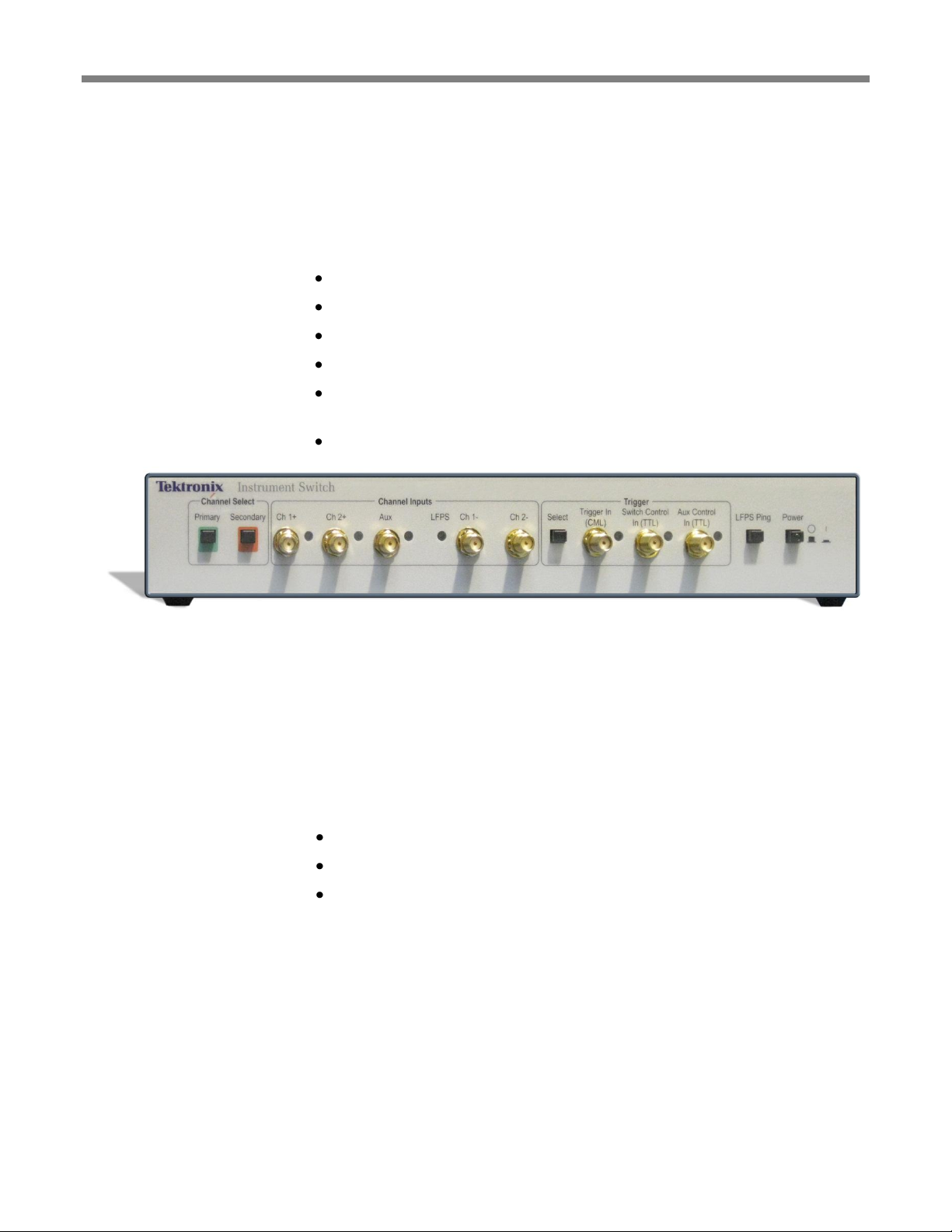
The Tektronix Instrument Switch is a flexible device usable for general purpose
applications and specific inclusion in USB 3.0 compliance testing. For USB 3.0
testing, the switch features a pattern generator for generation of Low Frequency
Periodic Signaling (LFPS), used to ensure devices achieve loopback. Other features
include:
Manual switching between channels with front panel controls
Automated control via USB
Flexible triggering with multiple control choices
Two main input channels (Ch 1, Ch 2) with >10 GHz analog bandwidth
Single-ended to differential input channel for easily adding low frequency
signal generators to test setups
USB control and power with no need for additional external power
Figure 1: The Tektronix Instrument Switch
Manual Control
The Instrument Switch can be operated manually, using the pushbuttons and
connectors, with power supplied through the USB connection to a host instrument.
The Switch Control program and instrument drivers must be installed on the host
instrument to properly power the switch.
Switch Control
Program
Software control communication is through USB connection to a control host (such
as a Windows PC or BERTScope Analyzer).
The Switch Control software provides additional control features, including:
Duty Cycle setting for LFPS sequences
LFPS Polling/Ping/Reset selection
Custom LFPS type setup
The Switch Control program and instrument drivers must be installed on the host
instrument prior to connecting the USB cable.
Tektronix USB 3.0
Receiver Testing
Software
This Tektronix USB 3.0 Receiver Testing solution software is available for use with
the BERTScope Analyzer. Once installed on a PC, the testing software
communicates directly with the Switch Control program, for seamless operation
through the user interface.
The USB 3.0 Receiver Testing software also includes a detailed remote control
protocol for automated testing.
Getting Started
Tektronix Instrument Switch Instruction Manual 1
Page 12

Getting Started
Standard USB 2.0 cable
Instrument Switch Control Software CD-ROM
Driver and application/socket-server programs to be installed on a control host
(BERTScope Analyzer or Windows PC) connected to the Switch via USB.
Standard Accessories
2 Tektronix Instrument Switch Instruction Manual
Page 13

Operating Basics
The Instrument Switch is intended to be operated in a controlled laboratory
environment. It is intended to operate on a bench top, or on top of another
instrument such as the BERTScope Analyzer. There are four shock-absorbing feet
located on the bottom of the instrument.
This instrument draws operating power through a USB connection to a host
instrument, such as the BERTScope Analyzer or a Windows PC. No other power
source is required.
Note: The Instrument Switch drivers must be installed on the host instrument in
order to correctly supply power to the switch.
Connect the Instrument Switch to a BERTScope Analyzer or host PC via the USB
connector on the rear panel.
Press the Power button on the front panel. A lit green LED on the button indicates
that power is on.
Note: If you will be using a software switch control program, it should be installed
on the control host prior to connecting the switch.
The Instrument Switch serves as a regulated gateway for passing test signals to a
DUT. It can be operated using:
The physical pushbuttons and connectors
Switch Control software, installed on a control host
Tektronix USB 3.0 Receiver Testing software, installed on a control host
Software control communication is through USB 2.0 connection to a control host
(such as a BERTScope Analyzer or a Windows PC). The Switch Control program
should be installed on this control instrument prior to connecting the USB cable.
The Switch Control software is distributed on the CD-ROM supplied as a standard
accessory with the Instrument Switch.
Operating Basics
Power On Status
Setup
Tektronix Instrument Switch Instruction Manual 3
Page 14

Instrument Switch Operation
Figure 2 illustrates an example test setup incorporating the Instrument Switch.
Figure 2: Example Test Setup – Jitter Tolerance Test Cabling Diagram
The Instrument Switch allows the selection of one of four RF signals as its output:
Channel 1, through connectors on the front panel.
Channel 2, through connectors on the front panel.
Single-ended AUX Input, through a connector on the front panel. This
single-ended source is split into a differential signal by a balun internal to
the switch.
Built-in Low Frequency Periodic Signal (LFPS) generator, which provides
different types of USB 3.0 LFPS signals that are useful during USB 3.0
application testing. For instance, the USB 3.0 Receiver Testing solution
software uses this fourth source to initiate loopback training.
Once Primary, Secondary, and Trigger sources are set, the input Primary channel is
passed directly to output until a Trigger event occurs, prompting a change to the
Secondary channel.
Instrument Switch Operation
Installing the Instrument Switch in a Test Setup
Switch Signal Paths
4 Tektronix Instrument Switch Instruction Manual
Page 15
Instrument Switch Operation
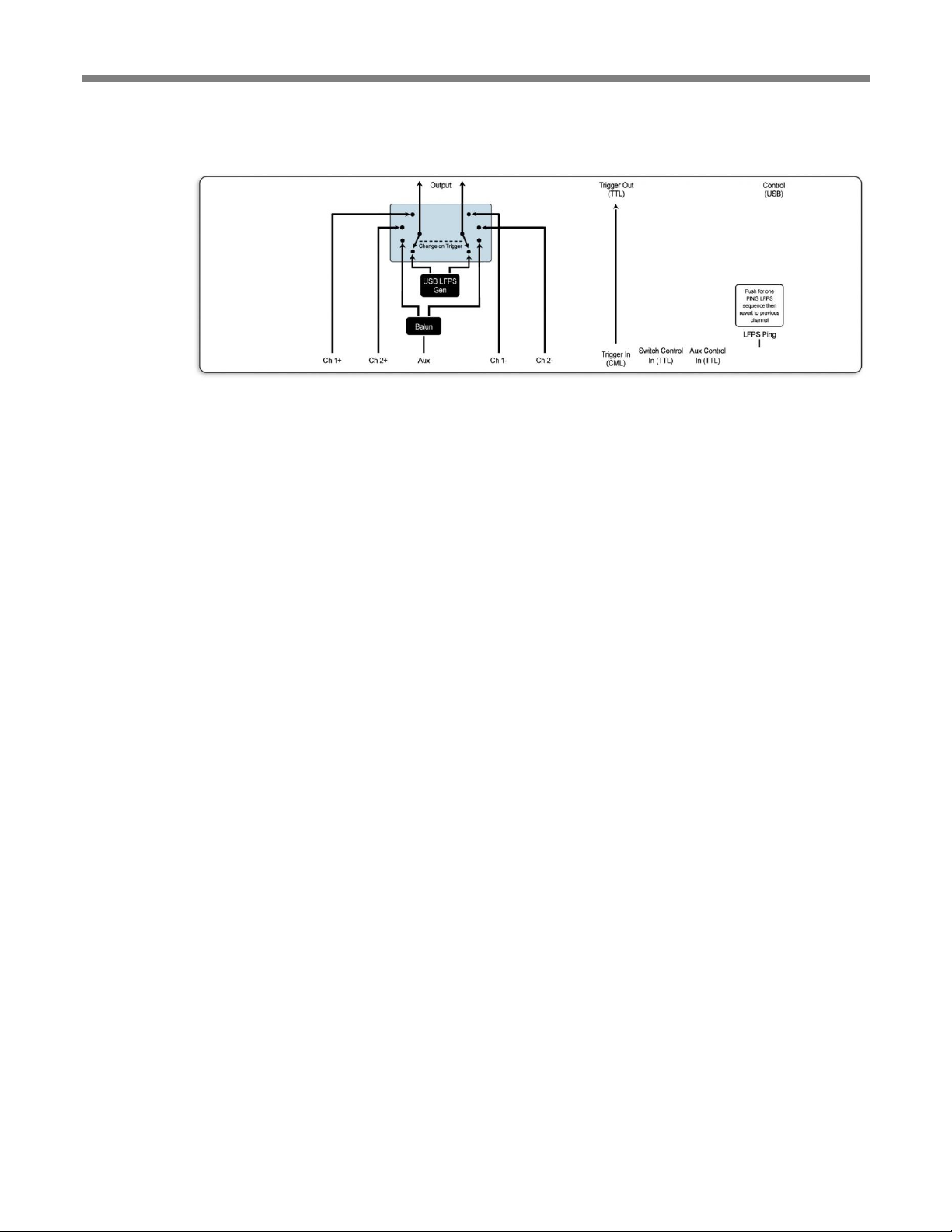
The following diagram (which appears on the top panel of the Instrument Switch) is
a straightforward depiction of the switching options.
Figure 3: Instrument Switch signal paths
Tektronix Instrument Switch Instruction Manual 5
Page 16
Manual Switch Control
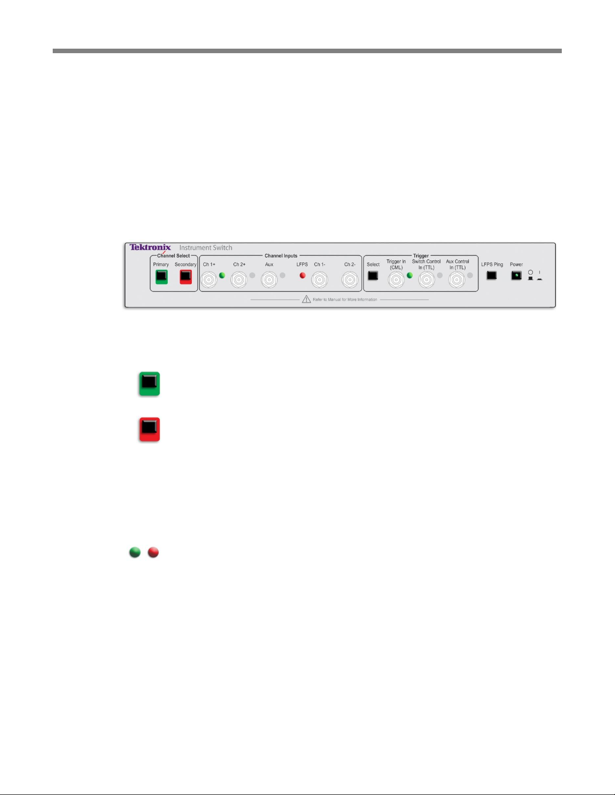
Testing signals are routed through the switch using the connectors on the front and
rear panels. Use the front panel pushbuttons set the Primary and Secondary
channels, select the Trigger source, and insert a one-time LFPS Ping.
The Instrument Switch is powered through USB connection to a host PC or
BERTScope Analyzer. The switch software drivers must be installed on the host
instrument in order to correctly power the switch.
Figure 4: Instrument Switch front panel controls and connectors
Channel Select
Primary
Secondary
Use these pushbuttons to select Primary and Secondary input channels. The Primary
channel is the source normally passed to the switch outputs. Upon a trigger event,
input switches to the Secondary channel, if one is selected.
Press the button to advance to the next channel in sequence: Channel 1 – Channel 2
– AUX – LFPS Generator. Hold the button down to cycle through the channels. The
switch will not physically change position until the button is released, allowing you
to change from, for example, Channel 1 to AUX, without enabling Channel 2 in
between.
Pressing the Primary Channel Select button clears any Secondary channel selection,
effectively ‘locking’ the switch to the Primary channel until a new Secondary
channel is selected.
When the switch is powered on, Channel 1 is selected as the Primary channel and
the LFPS generator as the Secondary channel.
Channel LEDs
An illuminated green LED indicates the Primary channel.
A red LED may be illuminated, indicating the Secondary channel if one is selected.
Channel 1 (+) In
SMA connector for a single-ended or differential (+) Channel 1 input, internally
AC-coupled.
Channel 2 (+) In
SMA connector for a single-ended or differential (+) Channel 2 input, internally
AC-coupled.
Auxiliary In
SMA connector; internally AC-coupled.
Limited to a maximum frequency of 100 MHz; an internal balun converts the
single-ended signal to a differential pair of signals for transmission to the switch
outputs. This is intended for use with an AFG or AWG, to generate custom lowspeed signaling.
Manual Switch Control
Switch Front Panel Controls and Connectors
6 Tektronix Instrument Switch Instruction Manual
Page 17

Manual Switch Control
LFPS Generator
Selects the internal LFPS generator as the channel source.
Channel 1 (–) In
SMA connector for a differential Channel 1 (–) input, internally AC-coupled.
Channel 2 (–) In
SMA connector for a differential Channel 2 (–) input, internally AC-coupled.
Trigger Select
This pushbutton selects a trigger input: Trigger In – Switch Control – AUX Control.
Only one trigger is enabled at a time, indicated by an illuminated green LED. Press
the button to enable the next trigger in sequence.
Hold the button down to cycle through the sources; the switch will not enable a new
trigger until the button is released, allowing you to change from, for example,
Trigger In to AUX Control, without enabling Switch Control in between.
Trigger LED
One of three green LEDs is illuminated to indicate the active Trigger Input.
Trigger In
(CML)
SMA connector. A rising edge will cause a switch to the Secondary channel, if one
has been selected.
Expected signal levels are CML, with nominal input voltages of 0 V for V(ih) and 400 mV for V(il). This input has protection circuitry that prevents the 3.3 V TTL
input trigger signal from causing damage to the switch.
Switch Control In
(3.3 V TTL)
SMA connector. A rising or falling edge of this 3.3 V TTL-level input will cause a
switch to the Secondary channel, if one has been selected.
Aux Control In
(3.3 V TTL)
SMA connector. A rising or falling edge of this 3.3 V TTL-level input will cause a
switch to the Secondary channel, if one has been selected.
LFPS Ping
The Ping pushbutton immediately switches output to the internal LFPS generator,
transmits a single LFPS sequence (a ‘Ping’), and immediately returns to the
previously selected Primary channel.
If the LFPS generator is selected as the Primary channel when a ping is instigated,
the switch will go from tri-state to LFPS to tri-state output.
If the LFPS generator is selected as the Secondary channel, a ping will switch from
whatever state the primary channel is in to LFPS, and then back to the previous
state of the Primary channel.
Power Button/LED
Press to power-on. A green LED in the button will light. Press the button again to
turn off power.
Tektronix Instrument Switch Instruction Manual 7
Page 18

Manual Switch Control
Figure 5: Instrument Switch rear panel connectors
Control (USB)
A USB B-type connector on the rear panel provides power and software control
through USB 2.0 connection to a host instrument.
Trigger Out
(3.3 V TTL)
The Trigger Out connector on the rear panel outputs a 3.3 V TTL-level signal that
has been internally converted from the CML-level Trigger In. This can be used to
trigger additional external equipment.
The source of the output signal(s) is determined by the Primary, Secondary, and
Trigger selections.
Output (–)
The Output (–) connector on the rear panel outputs a differential (–) signal. SMA
connector; internally AC-coupled.
Output (+)
The Output (+) connector on the rear panel outputs a differential (+) signal. SMA
connector; internally AC-coupled.
Switch Rear Panel Connectors
8 Tektronix Instrument Switch Instruction Manual
Page 19

USB Switch Control
Through the USB connection, software programs installed on a host instrument can
be used to manage switch operation.
The included Switch Control software program (on the Software CD-ROM shipped
with the Instrument Switch) provides options in addition to manual operation,
including:
Duty Cycle setting for LFPS sequences
LFPS Polling/Ping/Reset selection
Custom LFPS type setup
Figure 6: Switch Control Software user interface
USB Switch Control
Switch Control Software
Tektronix Instrument Switch Instruction Manual 9
Page 20

USB Switch Control
The Instrument Switch is an integral part of the Tektronix USB 3.0 Receiver Testing
solution. The USB 3.0 Receiver Testing software communicates directly with the
Switch Control program, managing all aspects of switch operation through one
interface.
Figure 7: Tektronix USB 3.0 Testing Software user interface
Remote Control
The USB 3.0 Testing software includes a detailed remote control protocol for
automated USB 3.0 receiver testing.
Remote control commands specifically for configuring and controlling the
Instrument Switch are listed here. A complete command protocol is included in the
USB 3.0 Receiver Testing software’s online Help System.
Protocol
Type
Description
Parameter(s)
CONN:SWITCH [bool]
R/W
Property
Connects or disconnects TCP/IP
communications to Switch using
default IP address and port
Boolean value indicating whether to connect (1)
or disconnect (0)
PREF:SAVE
Command
Save Preferences
PREF:SW:IP "text"
R/W
Property
Instrument Switch communications
TCP/IP Address
String IP address in the form 192.168.99.99
PREF:SW:PORT <int>
R/W
Property
Instrument Switch communications
TCP/IP Port
Decimal integer port number
PREF:SW:TO <int>
R/W
Property
Instrument Switch communications
Timeout
Decimal integer representing seconds
RXTEST:SW:COUNT
R-Only
Property
Returns number of frequencies in
receiver testing
Decimal integer value representing the number
of frequencies tested
USB 3.0 Testing Software
10 Tektronix Instrument Switch Instruction Manual
Page 21

USB Switch Control
RXTEST:SW:DISPL [enum]
R/W
Property
Selects whether to display a chart or
table during receiver testing
Possible values include: 0 = table, 1 = chart
RXTEST:SW:PROGRESS
R-Only
Property
Returns the index of the frequency
currently being tested
Decimal integer value representing the 0-based
index of the frequency being tested, or -1 if
testing is not being performed.
RXTEST:SW:RCOUNT
R-Only
Property
Returns number of rows in test results
from receiver test system
Decimal integer value representing the number
of test results contained in the receiver test
system results table
RXTEST:SW:RESULT [int]
R-Only
Property
Returns specified table row from the
receiver test system results table
Returns 5 values for specified row: Test
amplitude, Bits, Errors, BER, and Status strings.
Status values include: Blank, Skipped,
InProgress, Passed, NoSync, BERFailure,
ClockError, DataError, LimitReached,
Unknown.
RXTEST:SW:RUN [bool]
R/W
Property
Controls the run state of the receiver
test system.
Boolean value indicating whether the receiver
test system is running or not.
RXTEST:SW:STATUS
R-Only
Property
Returns receiver test system status
Possible return values include: NotRunning,
TestStarted, TestingFreq, and
LoopbackRequired.
Tektronix Instrument Switch Instruction Manual 11
Page 22

Specifications
Specifications
Analog Bandwidth (Ch 1, Ch 2) ................... >10 GHz
Max. Input Voltage (Ch 1, Ch 2, AUX) ....... 3 V p-p per channel
Insertion Loss (Ch 1, Ch 2) ........................... 3 dB
Impedance ..................................................... 50 Ω
Switching Speed ........................................... 400 ns (typical)
Input/Output Connectors ............................... SMA 3.5 mm female
Power Supply ................................................ Via USB connection to a control host
(BERTScope Analyzer or Windows PC)
Software Control ........................................... Via USB connection to a control host
INPUTS
Channel 1+ ............................................. Single-ended / Differential (+)
Internally AC-coupled
Channel 2+ ............................................ Single-ended / Differential (+)
Internally AC-coupled
AUX In ................................................... Internally converted to differential
output
Internally AC-coupled
Max. Frequency ............................... 100 MHz
LFPS ....................................................... Internal LFPS generator
Max. Frequency ............................... 100 MHz
Channel 1– ............................................. Differential (–)
Internally AC-coupled
Channel 2–.............................................. Differential (–)
Internally AC-coupled
Trigger In................................................ CML
Nominal Voltage .............................. V(ih) 0 V
V(il) –400 mV
Switch Control........................................ 3.3 V TTL
AUX Control .......................................... 3.3 V TTL
OUTPUTS
Output – .................................................. Differential (–)
Output + ................................................. Single-ended / Differential (+)
Trigger Out ............................................. 3.3 V TTL (internally converted from
CML Trigger In)
ENVIRONMENTAL
Temperature, Operating ......................... +10 to 40 °C
Humidity ................................................ Non-condensing at 40 °C, 15 to 95%
12 Tektronix Instrument Switch Instruction Manual
Page 23

Maintenance
The exterior of the instrument may be cleaned using a soft cloth dampened with a
‘glass and office desk surface’ type cleaner. Do not use solvent or abrasive cleaning
agents.
The Channel and Trigger inputs and outputs use 3.5 mm SMA connectors. Should a
connector become damaged, replacements can be ordered from Tektronix.
Maintenance
Cleaning
Connector Replacement
Tektronix Instrument Switch Instruction Manual 13
Page 24

Troubleshooting
This normally means that the switch is not receiving power from the USB port to
which it is connected. Verify that the USB cable is securely connected between the
host PC/BERTScope Analyzer and the Tektronix Instrument Switch, and that the
host instrument is not in a low power (suspend) state.
When the Tektronix Instrument Switch is first powered on, the default configuration
is as follows:
The Primary channel is set to Channel 1.
The Secondary channel is set to the LFPS Generator channel.
The Trigger In (CML) input is selected.
The selection LEDs for these inputs should be lit. If the green power LED is the
only LED lit, this normally means that the Tektronix Instrument Switch was not
recognized and configured correctly by the host PC, typically because the switch
driver has not been installed on the host PC. Verify that the switch driver has been
installed on the host PC, or if necessary, reinstall the driver on the host system.
This behavior occurs if the currently selected trigger input is receiving a fast,
repeating trigger signal. The switch will continuously oscillate between the primary
and secondary channels in this case, and their LEDs will be perceived as orange
(actually oscillating between green and red).
Troubleshooting
Symptom #1: Power button pressed, green power LED does not light.
Symptom #2: Power button pressed, green power LED lights but the Channel 1
LED (green), LFPS LED (red) and/or Trigger In LED (green) are not lit.
Symptom #3: Two of the Channel Input Select LEDs are lit orange.
14 Tektronix Instrument Switch Instruction Manual
 Loading...