

Page 1

User Manual
IGS-5034-00
Fibre Channel Transceiver Test System
070-9969-00
Page 2

Copyright Tektronix, Inc. All rights reserved. Licensed software products are owned by T ektronix or its suppliers and
are protected by United States copyright laws and international treaty provisions.
Use, duplication, or disclosure by the Government is subject to restrictions as set forth in subparagraph (c)(1)(ii) of the
Rights in T echnical Data and Computer Software clause at DFARS 252.227-7013, or subparagraphs (c)(1) and (2) of the
Commercial Computer Software – Restricted Rights clause at F AR 52.227-19, as applicable.
T ektronix products are covered by U.S. and foreign patents, issued and pending. Information in this publication supercedes
that in all previously published material. Specifications and price change privileges reserved.
Printed in the U.S.A.
T ektronix, Inc., P.O. Box 1000, Wilsonville, OR 97070–1000
TEKTRONIX and TEK are registered trademarks of T ektronix, Inc.
Page 3

Table of Contents
Getting Started
Operating Basics
Reference
General Safety Summary iii. . . . . . . . . . . . . . . . . . . . . . . . . . . . . . . . . . . .
Preface v. . . . . . . . . . . . . . . . . . . . . . . . . . . . . . . . . . . . . . . . . . . . . . . . . . .
Contacting Tektronix v. . . . . . . . . . . . . . . . . . . . . . . . . . . . . . . . . . . . . . . . . . . . . .
Product Description 1–1. . . . . . . . . . . . . . . . . . . . . . . . . . . . . . . . . . . . . . . . . . . . . . .
Cautions and Warnings 1–3. . . . . . . . . . . . . . . . . . . . . . . . . . . . . . . . . . . . . . . . . . . . .
Laser Safety 1–3. . . . . . . . . . . . . . . . . . . . . . . . . . . . . . . . . . . . . . . . . . . . . . . . .
Static Precautions 1–4. . . . . . . . . . . . . . . . . . . . . . . . . . . . . . . . . . . . . . . . . . . . .
General 1–4. . . . . . . . . . . . . . . . . . . . . . . . . . . . . . . . . . . . . . . . . . . . . . . . . . . . .
General Maintenance 1–5. . . . . . . . . . . . . . . . . . . . . . . . . . . . . . . . . . . . . . . . . . . . . .
Functional Check 2–1. . . . . . . . . . . . . . . . . . . . . . . . . . . . . . . . . . . . . . . . . . . . . . . . .
Installing the DUT Adapter 2–2. . . . . . . . . . . . . . . . . . . . . . . . . . . . . . . . . . . . . . . . .
Installing the DUT 2–2. . . . . . . . . . . . . . . . . . . . . . . . . . . . . . . . . . . . . . . . . . . . . . . .
Running the T ests 2–4. . . . . . . . . . . . . . . . . . . . . . . . . . . . . . . . . . . . . . . . . . . . . . . . .
List of Figures
T est Descriptions 3–1. . . . . . . . . . . . . . . . . . . . . . . . . . . . . . . . . . . . . . . . . . . . . . . . .
Operator Troubleshooting Procedures 3–2. . . . . . . . . . . . . . . . . . . . . . . . . . . . . . . . .
Three Components in a Row Fail the Same T est 3–2. . . . . . . . . . . . . . . . . . . . .
“Bad Scan” Message 3–2. . . . . . . . . . . . . . . . . . . . . . . . . . . . . . . . . . . . . . . . . . .
SFTP_DUT or Golden_DUT Fails T est 3–2. . . . . . . . . . . . . . . . . . . . . . . . . . . .
Other Problems 3–2. . . . . . . . . . . . . . . . . . . . . . . . . . . . . . . . . . . . . . . . . . . . . . .
Figure 1–1: The DUT: fibre channel transceivers 1–1. . . . . . . . . . . . . . . .
Figure 1–2: IGS-5034-00 Fibre Channel Transceiver Test System 1–2. . .
Figure 1–3: Wrist strap grounding connections 1–5. . . . . . . . . . . . . . . . . .
Figure 2–1: Opening the test fixture 2–2. . . . . . . . . . . . . . . . . . . . . . . . . . .
Figure 2–2: Inserting an MIM DUT in the test fixture 2–3. . . . . . . . . . . .
Figure 2–3: Inserting an OESW DUT in the adapter 2–4. . . . . . . . . . . . .
Figure 2–4: Ready for DUT Display 2–5. . . . . . . . . . . . . . . . . . . . . . . . . . .
Figure 2–5: DUT Test in Progress Display 2–5. . . . . . . . . . . . . . . . . . . . . .
Figure 2–6: Test Results Display 2–6. . . . . . . . . . . . . . . . . . . . . . . . . . . . . .
IGS-5034-00 Fibre Channel Transceiver Test System User Manual
i
Page 4

Table of Contents
ii
IGS-5034-00 Fibre Channel Transceiver Test System User Manual
Page 5

General Safety Summary
Review the following safety precautions to avoid injury and prevent damage to
this product or any products connected to it. To avoid potential hazards, use this
product only as specified.
Only qualified personnel should perform service procedures.
While using this product, you may need to access other parts of the system. Read
the General Safety Summary in other system manuals for warnings and cautions
related to operating the system.
To Avoid Fire or
Personal Injury
Use Proper Power Cord. Use only the power cord specified for this product and
certified for the country of use.
Use Proper V oltage Setting. Before applying power, ensure that the line selector is
in the proper position for the power source being used.
Connect and Disconnect Properly . Do not connect or disconnect probes or test
leads while they are connected to a voltage source.
Ground the Product. This product is grounded through the grounding conductor
of the power cord. To avoid electric shock, the grounding conductor must be
connected to earth ground. Before making connections to the input or output
terminals of the product, ensure that the product is properly grounded.
Observe All Terminal Ratings. To avoid fire or shock hazard, observe all ratings
and marking on the product. Consult the product manual for further ratings
information before making connections to the product.
Do not apply a potential to any terminal, including the common terminal, that
exceeds the maximum rating of that terminal.
Do Not Operate Without Covers. Do not operate this product with covers or panels
removed.
Use Proper Fuse. Use only the fuse type and rating specified for this product.
Avoid Exposed Circuitry. Do not touch exposed connections and components
when power is present.
Wear Eye Protection. Wear eye protection if exposure to high-intensity rays or
laser radiation exists.
Do Not Operate With Suspected Failures. If you suspect there is damage to this
product, have it inspected by qualified service personnel.
Do Not Operate in Wet/Damp Conditions.
Do Not Operate in an Explosive Atmosphere.
IGS-5034-00 Fibre Channel Tester System User Manual
iii
Page 6

General Safety Summary
Keep Product Surfaces Clean and Dry .
Provide Proper Ventilation. Refer to the manual’s installation instructions for
details on installing the product so it has proper ventilation.
Symbols and Terms
T erms in this Manual. These terms may appear in this manual:
WARNING. Warning statements identify conditions or practices that could result
in injury or loss of life.
CAUTION. Caution statements identify conditions or practices that could result in
damage to this product or other property.
T erms on the Product. These terms may appear on the product:
DANGER indicates an injury hazard immediately accessible as you read the
marking.
WARNING indicates an injury hazard not immediately accessible as you read the
marking.
CAUTION indicates a hazard to property including the product.
Symbols on the Product. The following symbols may appear on the product:
WARNING
High Voltage
iv
Protective Ground
(Earth) T erminal
IGS-5034-00 Fibre Channel Tester System User Manual
CAUTION
Refer to Manual
Double
Insulated
Page 7

Preface
Contacting Tektronix
This document contains operating instructions for the IGS-5034-00 Fibre
Channel Transceiver Test System (referred to in this document as “test system”
or “system”). Information about maintenance, repair, and modification of the test
system is located in the manuals listed below.
The following manuals contain system-level information:
H System Administrator Procedures: IGS-5034-00 Fibre Channel Transceiver
Test System Instruction Manual
H Technician Procedures: IGS-5034-00 Fibre Channel Transceiver Test System
Instruction Manual
Product manuals for individual system components are also provided.
Service
Support
For other
information
To write us Tektronix, Inc.
Contact your local Tektronix distributor or sales office. Or, visit
our web site for a listing of worldwide service locations.
http://www.tek.com
In North America:
1-800-TEK-WIDE (1-800-835-9433)
An operator will direct your call.
P.O. Box 1000
Wilsonville, OR 97070-1000
IGS-5034-00 Fibre Channel Transceiver Test System User Manual
v
Page 8

Preface
vi
IGS-5034-00 Fibre Channel Transceiver Test System User Manual
Page 9

Getting Started
Page 10

Page 11

Getting Started
Product Description
This chapter contains basic information that you need to know before operating
the test system.
The test system performs manufacturing product verification testing on fibre
channel transceivers. Figure 1–1 shows the fibre channel transceivers. This
manual refers to fibre channel transceiver as a device under test (DUT).
MIM 266
OE1063SW
Figure 1–1: The DUT: fibre channel transceivers
Using the test system you can quickly verify whether the DUT is good or bad.
The test system checks specific parameters of the DUT in areas such as
bit-error-rate, optical levels, and pulse parameters. After testing the DUT, the
system displays a message telling you if the DUT passed or failed. System
software also documents test results for each DUT tested; this test data is
accessible by the system administrator and the line technician.
MIM531
MIM1063
IGS-5034-00 Fibre Channel Transceiver Test System User Manual
1–1
Page 12
Getting Started
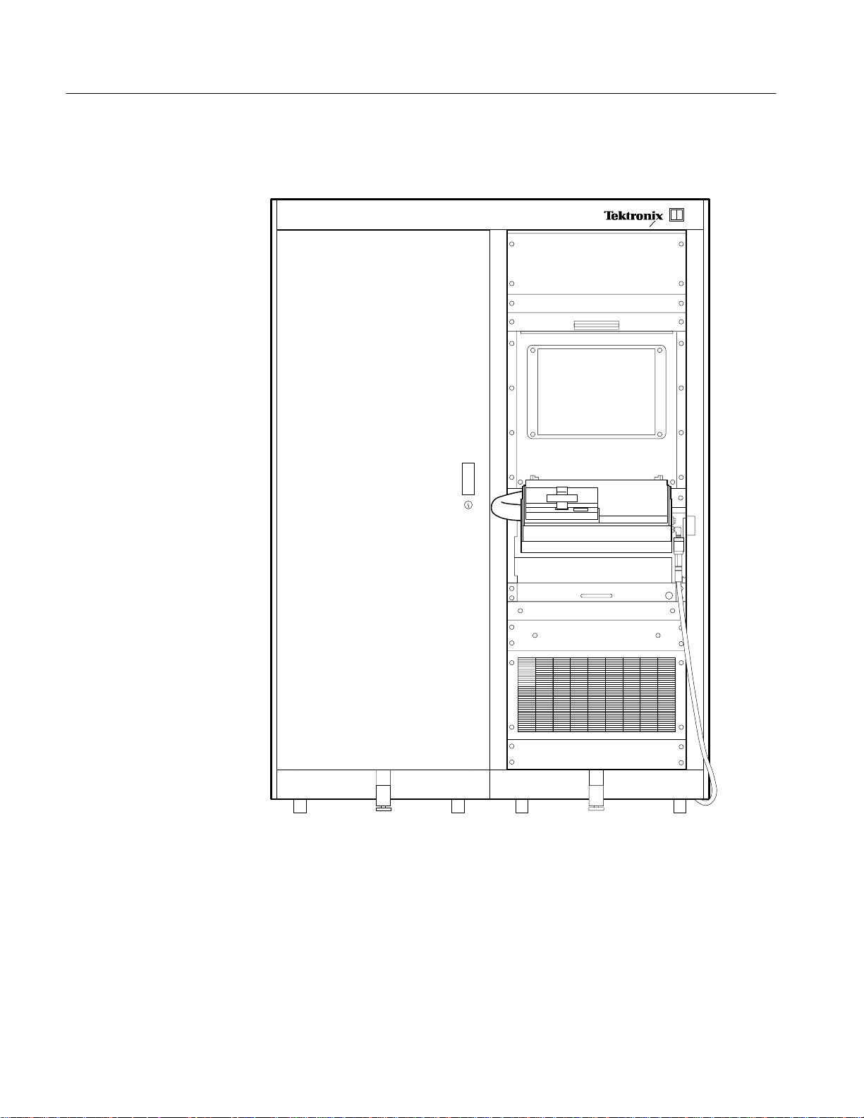
Figure 1–2 shows the test system as it appears during normal operation.
1–2
Figure 1–2: IGS-5034-00 Fibre Channel Transceiver Test System
IGS-5034-00 Fibre Channel Transceiver Test System User Manual
Page 13

Cautions and Warnings
Getting Started
Before you operate the test system, you must become familiar with the following
important information.
Laser Safety
The test system has three sources of laser light:
H An active DUT inserted into the test fixture with power applied
H The Symbol Technologies, Inc. LS 1220 bar code scanner
H The Broadband Communications Products, Inc. laser source instrument
The DUT, inserted into the test fixture with power applied, is a Class I laser
product. The bar code scanner (another Class I laser product) is also located
inside the test fixture housing. The design of the test fixture protects the operator
from exposure to harmful laser light levels: when the test fixture lid is opened
laser light is not present, and during testing (when the lid is closed) laser light is
contained inside the fixture.
NOTE. In normal operating mode, the test fixture and system comprise a Class I
laser DUT due to several safety interlocks. The output from a Class I laser is safe
to view without special eye protection.
Under normal operating conditions (rear test system doors closed and locked, and
front-panel protective covers in place), the Broadband Communications
Products, Inc. laser source instrument, a Class IIIb product, is inaccessible to the
operator and thus poses no hazard.
The test system provides three different safety interlocks in an attempt to prevent
exposure to harmful laser light. First, the software does not enable the optical
path until the lid is closed and a valid DUT is detected. Second, the hardware is
electrically prevented from completing the optical path for the Class III source
when the lid is open. Third, the mechanical design of the fixture completely
encloses the area where the light might be present.
WARNING. The operator is protected from harmful laser light levels during
normal operation. However, during servicing procedures a Class IIIb laser
product is accessible. Servicing procedures must not be performed by the
operator. All servicing procedures must be referred to qualified technical
personnel, trained in laser safety procedures.
IGS-5034-00 Fibre Channel Transceiver Test System User Manual
1–3
Page 14

Getting Started
Static Precautions
DUTs are sensitive to static damage. When working with static-sensitive
components, you should observe the following standard anti-static precautions:
CAUTION. Failure to observe these anti-static precautions can result in damage
to the DUT being tested. Damage to electrical components may not be immediately apparent. Always follow the precautionary measures listed when handling
static-sensitive DUTs.
H Minimize handling of static-sensitive DUTs.
H Transport and store static-sensitive DUTs in their original containers or on
conductive foam. Label any package that contains static-sensitive DUTs.
H Discharge static voltage from your body by wearing a wrist strap when
handling these DUTs. Handling of these DUTs should be performed only at a
static-free workstation by qualified personnel. (See Figure 1–3 for wrist strap
connection location.)
H Don’t put anything capable of generating or holding a static charge on the
work surface.
H Avoid handling DUTs in areas that have a floor or work-surface covering
capable of generating a static charge.
General
H Pick up DUTs by the body, never by the leads or pins.
H Do not slide DUTs over any surface.
CAUTION. The body of the test fixture is capable of holding a static charge. You
should use an ionizer to nullify any static buildup on the test fixture. Make sure
that the ionizer is powered on and that the ionizer air flow toward the test fixture
is not obstructed.
Do not touch optical surfaces. Doing so can leave a residue on the optical surface
that interferes with the laser transmission/reception and causes faulty test results.
1–4
IGS-5034-00 Fibre Channel Transceiver Test System User Manual
Page 15

Getting Started
Figure 1–3: Wrist strap grounding connections
General Maintenance
It is important that the test system and its surrounding area be kept clean and
dust-free. Doing so reduces maintenance costs, down time, and ultimately
increases the accuracy and reliability of the test results.
It is also important that the DUT is handled properly, so that the DUT does not
add any further dust or dirt to the test fixture. Keep the optical connectors on the
DUT covered at all times except when testing.
Further cleaning and maintenance procedures are the responsibility of the
technician.
Grounding jacks for wrist strap plug
IGS-5034-00 Fibre Channel Transceiver Test System User Manual
1–5
Page 16

Getting Started
1–6
IGS-5034-00 Fibre Channel Transceiver Test System User Manual
Page 17

Operating Basics
Page 18

Page 19

Operating Basics
Functional Check
This chapter tells you how to run the production tests on a fibre channel
transceiver device under test (DUT).
NOTE. If you have not already done so, read the information in the Getting
Started chapter before continuing on with the following material. Getting Started
contains important information about handling the DUT under test and about
looking after the test system.
At the start of each shift, you should perform this functional check procedure to
make sure the test system is working properly. To do this, follow these steps:
1. Check that the test system is displaying a READY FOR DUT message.
2. Check that the correct DUT adapter is installed for the DUT you will be
testing (
MIMG, MIM 266, MIM 531, or OESW).
NOTE. If the correct DUT adapter is not installed, contact the line technician.
The system must be reconfigured when the DUT type is changed.
3. Install the SFTP_DUT in the test fixture. The test begins when you close the
lid of the test fixture. The rest of the test is automatic.
For instructions on how to install a DUT into the test fixture, refer to
Installing the DUT on page 2–2.
4. When the test system displays READY FOR GOLD, remove the SFTP_DUT
and replace it in its container.
5. Insert the appropriate Golden_DUT in the test fixture and close the lid.
NOTE. You must use the same type of Golden_DUT as the DUT you intend to test.
IGS-5034-00 Fibre Channel Transceiver Test System User Manual
2–1
Page 20

Operating Basics
When the test is complete, the system displays a PASS message or a SYSTEM
FAILURE message on the monitor. When the test system displays PASS, you
may remove the Golden_DUT and begin testing production DUTs.
If the test system displays SYSTEM FAILURE for either test, call the line
technician.
Installing the DUT Adapter
Only the technician should install the DUT adapter.
Installing the DUT
To install the DUT into the test fixture, follow these steps:
1. To open the test fixture, press the release handle and lift it, as shown in
Figure 2–1.
Press then lift
Figure 2–1: Opening the test fixture
2. Remove all protective caps from the DUT.
2–2
IGS-5034-00 Fibre Channel Transceiver Test System User Manual
Page 21

Operating Basics
3. Carefully insert the DUT into the DUT adapter in the test fixture (see Figure
2–2). Make sure the pins are seated correctly, and then press down gently
until the DUT is fully seated.
NOTE. It is important that you insert the DUT correctly in the test fixture.
Improper insertion can cause false test results.
Figure 2–2: Inserting the DUT in the DUT adapter
IGS-5034-00 Fibre Channel Transceiver Test System User Manual
2–3
Page 22

Operating Basics
For the OESW DUT, drop it straight down in front of the scallops until it
touches the back of the platform and slide the DUT into the connector. Figure
2–3 shows how to insert an OESW DUT.
Running the Tests
Figure 2–3: Inserting an OESW DUT in the adapter
4. Push the toggle switch to the “Capture” position to clamp the DUT firmly
into its final position.
5. Press down firmly on the lid to close the test fixture. The latch makes an
audible click when the lid is fully closed.
To remove the OESW DUT, squeeze the release tabs and push the DUT out from
the connector end.
The full sequence of tests takes approximately 3.5 minutes per DUT. However,
the DUT may fail a test part way through the sequence, causing the tests to be
terminated and the DUT to be rejected before the 3.5 minutes have lapsed.
2–4
IGS-5034-00 Fibre Channel Transceiver Test System User Manual
Page 23

Operating Basics
To perform the tests on the DUT, follow these steps:
1. When the test system displays a Ready message, you may install the DUT
into the test fixture. See Figure 2–4.
READY FOR DUT
Figure 2–4: Ready for DUT Display
2. Close the test fixture and the test sequence begins. The test system displays
which test is currently running. See Figure 2–5.
07
TESTS COMPLETED
OUT OF
09
Figure 2–5: DUT Test in Progress Display
WARNING. The test system locks the test fixture while testing the DUT. This is for
your protection. Do not attempt to open the test fixture until the tests are
completed (the system displays PASS or FAIL on the monitor).
3. When the system finishes the tests, check whether the DUT passed or failed.
The test system displays the results on the monitor. Figure 2–6 shows both
the PASS and FAIL displays. Each screen may contain additional instructions
beneath the PASS or FAIL message.
IGS-5034-00 Fibre Channel Transceiver Test System User Manual
2–5
Page 24

Operating Basics
PASS display is shown on
green background
PASS FAIL
FAIL display is shown on
red background
Figure 2–6: Test Results Display
4. Open the lid and push the toggle switch to the “Release” position to release
the clamps.
NOTE. Make sure that you check whether the device passed or failed the tests
before going on to test the next device. It is important that the failed parts be
properly handled and documented.
5. Remove the device when the tests are complete. Place the device in the
correct bin, for passed or failed devices.
2–6
IGS-5034-00 Fibre Channel Transceiver Test System User Manual
Page 25

Reference
Page 26

Page 27

Reference
Test Descriptions
This chapter provides a short description of the tests and some procedures to
follow if you experience difficulties with the test system.
The system performs a number of tests on each component, testing that the
component is functional and that it performs as specified.
The system performs the tests in order, from most basic to most complex. For
most of the basic tests, if the component fails it is rejected and no further tests are
performed on that component. This saves testing time.
The following is a brief description of the tests performed on the DUT. The tests
are divided into four main categories, listed in order of execution:
DUT Initialization T ests. These tests check the most basic characteristics of the
DUT, relating to the power supply.
DUT Optical Calibration T ests. These tests set the optical power levels of the
transmit portion of the DUT. These calibration settings are implemented through
the EEPOT signal connections on the test fixture.
If any of the DUT Optical Calibration Tests fail, the test system will not perform
any more tests, and will reject the DUT. This is because other tests will probably
fail if the DUT is unable to have properly calibrated optical power levels.
Functional Tests. These tests check the integrity of optical and electrical paths
within the DUT.
Failure of some of the functional tests halts the testing process. Other tests do not
require that the testing process be halted if the test fails.
Performance Tests. These tests measure how well the DUT performs and how it
compares to tolerances. Test failures at this point are considered to be due to
out-of-tolerance performance.
All tests within this group are performed and the results entered into the test log;
test failures do not halt the test sequence.
IGS-5034-00 Fibre Channel Transceiver Test System User Manual
3–1
Page 28

Reference
Operator Troubleshooting Procedures
The following topics describe the problems that you may encounter, along with
suggestions for how you should deal with them.
Three Components in a
Row Fail the Same Test
“Bad Scan” Message
SFTP_DUT or
Golden_DUT
Fails Test
Other Problems
When three components in a row fail the same test, you should check that the
system is operating correctly. Refer to Functional Check on page 2–1, and
perform the Golden_DUT portion of the test. If the system passes, continue
testing components. If the system fails, call the line technician.
The test fixture is unable to read the bar code on the DUT. Check the bar code on
the DUT. The bar code should be readable (not torn or smudged), correctly
aligned, and right side up. If the bar code is correctly placed and undamaged, call
the line technician.
If either of these tests fail, call the line technician.
If you are experiencing other problems with the test system, or if the solutions
proposed above do not work, call the line technician for assistance.
3–2
IGS-5034-00 Fibre Channel Transceiver Test System User Manual
Page 29

Page 30

 Loading...