

Page 1

Software Version 7.13.2
Tektronix Communications | For Licensed Users | Unauthorized Duplication and Distribution Prohibited
Iris Packet Broker (IPB)
Hardware Installation and Maintenance
Guide
Powered by VSS Monitoring
Page 2

Copyright © Tektronix, Inc. All rights reserved. Printed in the USA. Tektronix products are covered
Tektronix Communications | For Licensed Users | Unauthorized Duplication and Distribution Prohibited
by U.S. and foreign patents, issued and pending. Information in this publication supersedes that in
all previously published material. Specification and price change privileges reserved. TEKTRONIX
and TEK are registered trademarks of Tektronix, Inc. The GeoProbe system uses the SmartHeap
product for memory management. SmartHeap is a product of Compuware Corporation,
Copyright © All rights reserved. All other trade names
trademarks or registered trademarks of their respective companies.
Tektronix Communications
3033 W President George Bush Highway
Plano, Texas 75075
+1 469-330-4000 (voice)
www.tekcomms.com W
eb site
referenced are the service marks,
uadocfeedback@tektronix.com (T
uadocfeedback@tektronix.com (T
Plano, Texas USA - serves North America, So
+1 469-330-4581 (Customer Support voice)
uaservice@tek.com (Customer Suppo
London, England UK - serves Northern
+44-1344-767-100 (Customer Support voice)
uaservice-uk@tek.com (Customer Supp
Frankfurt, Germany DE - serves Central Europe and Middle East
+49-6196-9519-250 (Customer Support voice)
uaservice-de@tek.com (Cu
Padova, Italy IT - serves Southern Europe and Middle East
+39-049-762-3832 (Customer Support voice)
uaservice-it@tekc.com (Customer
Melbourne, Australia - serves Australia
+61 396 330 400 (Customer Support voice)
uaservice-ap@tek.com (Cu
Singapore - serves Asia and the Pacific Rim
+65 6356 3900 (Customer Support voice)
uaservice-ap@tek.com (Cu
echnical Publications email)
echnical Publications email)
uth America, Latin America
rt USA email)
Europe, Middle East, and Africa
ort UK email)
stomer Support DE email)
Support IT email)
stomer Support Australia and APAC email)
stomer Support APAC and Australia email)
Tektronix Communications, Inc. Proprietary Information
992-0499-08-001-140228
The products and specifications, configurations, and other technical information regarding the
services describ
statements, technical information, and recommendations contained in this document are believed
to be accurate and reliable but are presented “as is” without warranty of any kind, express or
implied. Users must take full responsibility for their application of any products specified in this
document. Tektronix, Inc. makes no implied warranties of merchantability or fitness for a purpose
as a result of this document or the information described or referenced within, and all other
warranties, express or implied, are excluded.
Except where otherwise indicated,
planned capabilities and intended functionality offered by the product and version number
identified on the front of this document. Screen images depicted in this document are
representative and intended to serve as example images only. Wherever possible, actual screen
images are included.
ed or referenced in this document are subject to change without notice. All
the information contained in this document represents the
Page 3

User Documentation
Table of Contents
Tektronix Communications | For Licensed Users | Unauthorized Duplication and Distribution Prohibited
What’s New in IPB Hardware Maintenance Version 7.13.2? ......................................... 3
Chapter 1 Iris Packet Broker Introduction ............................................................................................ 4
Iris Packet Brokers........................................................................................................ 4
IPB Be
nefits.................................................................................................................. 5
IPB Base Features ........................................................................................................ 6
Chapter 2 IPB Hardware Reference ..................................................................................................... 7
IPB Models ................................................................................................................... 7
IPB Ch
assis Components ............................................................................................. 9
IPB220 and IPB420 Front Panels..................................................................... 9
IPB220 and IPB420 Rear Panel ..................................................................... 11
IPB220 and IPB420 Chassis LEDs ............................................................................. 12
IPB220 Chassis Port LEDs ............................................................................ 13
IPB Interconnection Support ....................................................................................... 14
IPB Chassis Modules.................................................................................................. 15
IPB220 and IPB420 1G/10G Chassis Module LEDs ...................................... 16
IPB420 40G Chassis Module LEDs................................................................ 16
FP100 Fuse Panel ...................................................................................................... 17
IPB System Level Alarms ............................................................................................ 18
Chapter 3 IPB Installation ..................................................................................................................
Overview .................................................................................................................... 19
Ha
rdware Installation .................................................................................................. 20
Fuse Panel Power Cabling (DC Units Only) ................................................................. 21
Terminal and Wiring Recommendations......................................................... 23
Initial System Configuration......................................................................................... 24
Connecting IPB Network Ports ................................................................................... 28
IPB IrisView Admin Configuration ................................................................................ 28
Configure IPB Settings................................................................................... 29
Bind G10s to IPB420 Devices........................................................................ 30
Bind G10s and IPB Devices to an Aggregation Cluster .................................. 32
Chapter 4 IPB System Operating Specifications ................................................................................ 34
Overview .................................................................................................................... 34
19
Iris Packet Broker (IPB) 7.13.2 1
Hardware Installation and Maintenance Guide
Page 4

Rev. 001-140228 Table of Contents
Tektronix Communications | For Licensed Users | Unauthorized Duplication and Distribution Prohibited
IPB Physical Dimensions .............................................................................................35
IPB Power and Heat Specifications .............................................................................35
IPB Environmental Specifications .................................................................................36
Chapter 5 IPB Software Upgrades......................................................................................................37
IPB Upgrades ..............................................................................................................37
Pr
erequisites................................................................................................................37
To Verify IPB Software Packages.................................................................................38
To Create a IPB Software Upgrade Campaign.............................................................38
Upgrading G10 Probes Bound to IPB.............................................................39
Upgrading IPBs Bound to an Aggregation Cluster ..........................................39
Campaign Status............................................................................................40
Backing Up and Restoring an IPB Configuration ..........................................................40
Backup an IPB Configuration ..........................................................................40
Restore an IPB Configuration..........................................................................41
Chapter 6 IPB Maintenance Guidelines...............................................................................................42
IPB Maintenance Procedures ......................................................................................42
Air Filter
s .....................................................................................................................43
Removing the Chassis Air Filter.......................................................................43
Removing the IPB220 Chassis Module Air Filter..............................................45
Power Supplies ...........................................................................................................46
Replacing a Power Supply .......................................................................46
Fan Tray ......................................................................................................................47
Chassis Modules .........................................................................................................48
Iris Packet Broker (IPB) 7.13.2 2
Hardware Installation and Maintenance Guide
Page 5

WHAT’S NEW IN IPB HARDWARE MAINTENANCE VERSION 7.13.2?
Tektronix Communications | For Licensed Users | Unauthorized Duplication and Distribution Prohibited
Feature ID Description Refer To:
F-02339 Support for IPB420 40
The IPB420 supports 40G chassis modules, supporting up to 16
connections per IPB.
Support for IPB420/IPB220 Configuration from IrisView
The IPB System Management Web GUI can now be accessed
om IrisView.
fr
Support for IPB420/IPB220 Software Upgrades from IrisView
Administrators can now perform IPB software upgrades using the
is Admin Software tab.
Ir
G Interface
IPB Models
IPB Chassis Modules
Configure IPB Settings
IPB Software Upgrades
Rev. 001-140228
Page 6
User Documentation
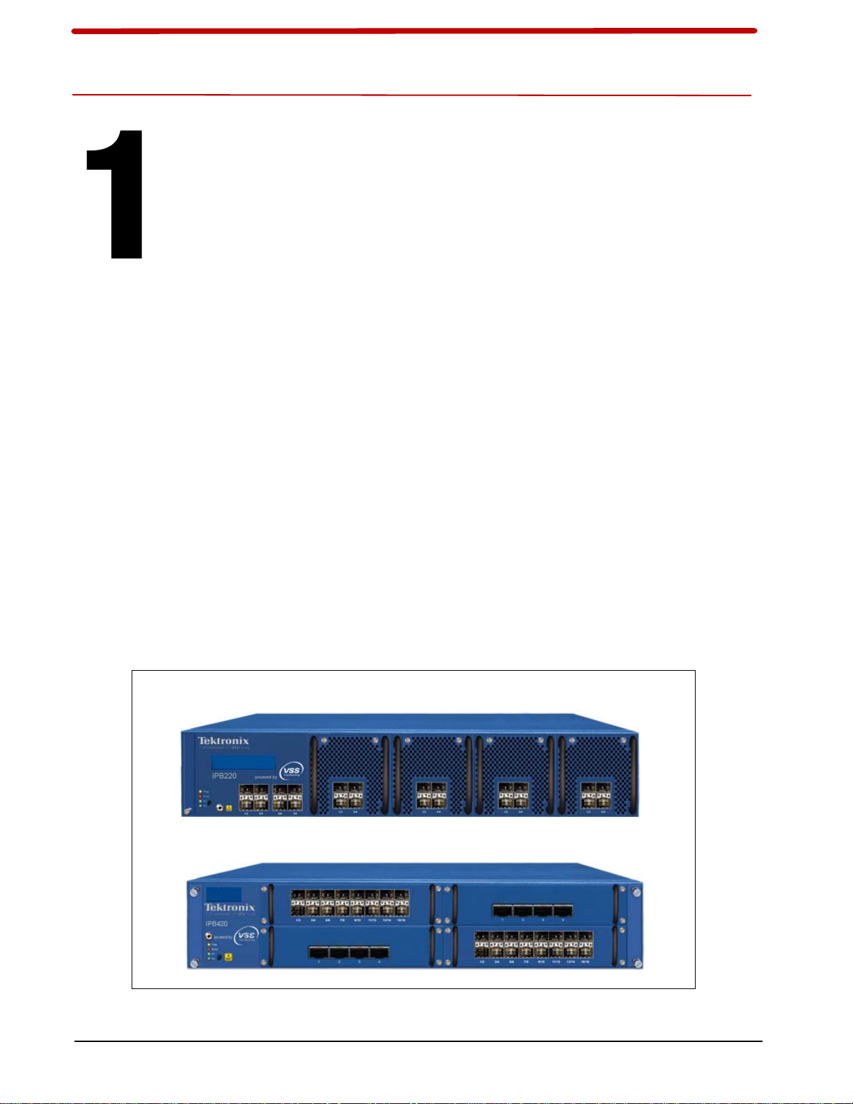
IRIS PACKET BROKERS
IPB220
IPB420
Tektronix Communications | For Licensed Users | Unauthorized Duplication and Distribution Prohibited
Iris Packet Brokers (IPBs) enable you to more effectively utilize your existing Tektronix
Communications monitoring solutions, simplify operational complexity, and realize a higher
ROI from additional cost savings and service quality improvements. IPB intelligent stacking
technology, vMesh, enables traffic capture devices to be deployed in a redundant, low-latency
mesh for total, dynamic, fault-tolerant visibility.
Iris Packet Broker
Introduction
Figure 1.1 - Iris Packet Brokers
Iris Packet Broker (IPB) 7.13.2 4
Hardware Installation and Maintenance Guide
Page 7

Rev. 001-140228
Tektronix Communications | For Licensed Users | Unauthorized Duplication and Distribution Prohibited
Iris Packet Broker Introduction
1
With the visionary vMesh approach to architecture, you get the flexibility and modularity to
deploy just the appliances you need, when you need them, with the ability to scale link-layer
visibility and data access to a system-level architecture with up to 256 ports globally. The
business benefits include more flexible capital requirements, high tool utilization and ROI, and
lower operating costs.
Designed specifically to address high bandwidth inter
faces and datacenter applications, the
NEBS compliant Iris Packet Broker (IPB) features a scalable, modular architecture that
bridges the gap between 1 GigE, 10 GigE, and 40 GigE networks. They also provide all of the
intelligent network packet functionality on a large scale. Each model supports a maximum of
four SFP+ chassis modules or that support different features, port densities, and port speeds
up to a maximum line rate throughput of 240 Gbps for the IPB220 series and 640 Gbps for the
IPB420. Additionally, ports and features are enabled as they are needed by license key. Any
port can be designated as an ingress/input or an egress/output port.
Hardware-based filtering a
llows traffic to be distinguished according to source and destination
MAC/IP address as well as by specific protocols, such as HTTP, VoIP, GTP, and LTE. A
custom filter offers more granular specification of a filter with the payload of a packet. Filters
can be ingress, egress, and overlapping.
All IPB models support symmetrical L2 to L4 load balanc
ing. Session aware load balancing is
provided by TD140. Select IPB models have optional features including port stamping, time
stamping, and microburst protection. To feed third party tools, select IPB models have optional
features including protocol/tag stripping (GTP, VLAN, MPLS) and conditional packet slicing.
All IPB models support a connection between multiple unit
s which enables up to 256 ports at a
single site. In addition, IPB can be deployed in a redundant, low-latency mesh for total,
dynamic fault-tolerant visibility. Select IPB models have an option to support inter-connected
IPBs over a LAN or WAN using TCP which enables backhaul of traffic from remote sites to a
central monitoring location. To protect against data attacks during backhaul, secure data
encryption (AES) is supported. Redundant hot-swappable power supplies, fans and air filters
allow seamless transitions between power systems and ensure uptime.
IPBs are an add-on to TD140 deployments; they do not replace TD140s.
IPB BENEFITS
The IPB provides the following benefits:
Gain link-layer visibility and data access across entire network
Centralize tools while increasing their reach
Quickly provision new tools by eliminating SPAN port contention
Higher port density with flexibility in speed and media
Iris Packet Broker (IPB) 7.13.2 5
Hardware Installation and Maintenance Guide
Page 8

Rev. 001-140228
Tektronix Communications | For Licensed Users | Unauthorized Duplication and Distribution Prohibited
IPB BASE FEATURES
The IPB provides the following base features:
Hardware-Based L2-L4 Filtering and Custom Offset Filtering
Define ingress to egress mapping
-1-to-1
- 1-to-Many (replicates data)
- Many-to-1 (aggregates data)
- Many-to-Many (replicates and aggregates data)
Automatic, symmetrical L2-L4 load balance of egress ports
- MAC Destination and/or Source
- IP Destination and/or Source
Iris Packet Broker Introduction
1
- IP and TCP/UDP Combinations
vMesh Stacking (connected by cables) provides up to 256 ports across multiple units.
G10s having an IIC100 configuration are limited to 24 total ingress ports.
Iris Packet Broker (IPB) 7.13.2 6
Hardware Installation and Maintenance Guide
Page 9

User Documentation
IPB MODELS
Tektronix Communications | For Licensed Users | Unauthorized Duplication and Distribution Prohibited
IPB Hardware
Reference
Tektronix Communications offers the following Iris Packet Broker (IPB) models:
IPB220 Base
IPB220 Advanced
IPB420
Table 2.1 shows the features available for each IPB model.
Table 2.1 - IPB Feature Support per Model
Feature IPB Model
Selective Port Aggregation and/or Replic
Layer 2 to Layer 4 Filtering
Symmetrical L2 to L4 Load Balancing
NTP or PTP timing
vMesh Direct Connect (connected by cable)
Integrated with IrisView Alarms and System Health
visibility
ation
IPB220
Base
IPB220
Advanced
IPB420
Iris Packet Broker (IPB) 7.13.2 7
Hardware Installation and Maintenance Guide
Page 10

Rev. 001-140228
Tektronix Communications | For Licensed Users | Unauthorized Duplication and Distribution Prohibited
IPB Hardware Reference
Table 2.1 - IPB Feature Support per Model (Continued)
Feature IPB Model
2
Maximum ports
Integration with GeoProbe platform family
1G or 10G Ethernet port
40G Ethernet port
Time & Port Stamping
Option to disable time and port stamping on egress
Within a GTP tunnel, L3 and L4 Filtering, 10G
Microburst Protection (High Data Burst Buffer)
Protocol/Tag Stripping (GTP, VLAN, MPLS)
vMesh over IP (Interconnect IPB over TCP/IP)
IPB220
Base
24 24, up to 16
IPB220
IPB420
Advanced
64 1G/10G and/or
ports have
advanced
features
16 40G
G10 only
Iris Packet Broker (IPB) 7.13.2 8
Hardware Installation and Maintenance Guide
Page 11

Rev. 001-140228
Chassis
LEDs
Control
Button
LCD
Display
Chassis
Module
Air Filter
ESD
Chassis
Air
Filter
1G/10G
Ports
Chassis
LEDs
Control
Button
LCD
Display
ESD
Chassis
Air
Filter
IPB220
IPB420
Chassis
Air
Filter
1G/10G Chassis Modules (4 port)
40G Chassis Module
40G Chassis Module
1G/10G Chassis Module
1G/10G Chassis Module
Tektronix Communications | For Licensed Users | Unauthorized Duplication and Distribution Prohibited
IPB CHASSIS COMPONENTS
IPB220 and IPB420 Front Panels
Figure 2.1 shows the front panels for the IPB220 and IPB420.
IPB Hardware Reference
2
Figure 2.1 - IPB220 and IPB420 Front Panels
Iris Packet Broker (IPB) 7.13.2 9
Hardware Installation and Maintenance Guide
Page 12

Rev. 001-140228
Tektronix Communications | For Licensed Users | Unauthorized Duplication and Distribution Prohibited
Item Description
Table 2.2 describes the IPB Front Panel components.
Table 2.2 - IPB Front Panel Component Descriptions
IPB220 IPB420
IPB Hardware Reference
2
Air Filter
One replaceable chassis air filter.
One replaceable air filter on each
Two replaceable chassis air filters.
installed IPB220 chassis module.
Control button
Ethernet Ports
Press briefly to page through LCD display.
8 1G/10G ports built into chassis.
4 1G/10G ports on each installed
1G/10G Chassis Module: 16 ports on
IPB220 chassis module (up to 16
additional ports).
40G Chassis Module: 4 ports on each
each installed chassis module (up to
64 ports).
installed chassis module (up to 16
ports).
Ports can be configured as ingress or egress ports based on configuration
requirements. Refer to IPB IrisView Admin Configuration or the
User Guide
for details.
LCD Display Displays system information: product model, sof
system error messages.
ESD Electro-static Discharge (ESD) connector fo
r ESD devices to prevent electrical
damage.
LEDs Refer to IPB220 and IPB420 Chassis LEDs.
IPB Software
tware release, port status, and
Iris Packet Broker (IPB) 7.13.2 10
Hardware Installation and Maintenance Guide
Page 13
Rev. 001-140228
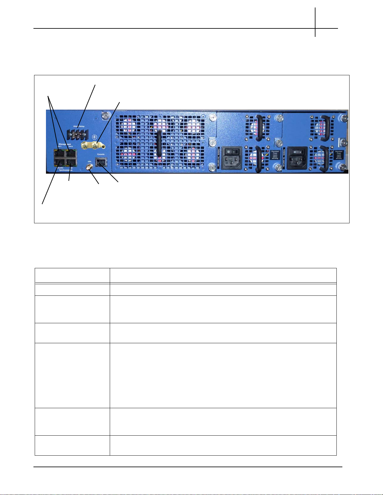
Grounding Lugs
Alarm Relay (not used)
Management
Ports (2)
Fan Tray
Power Supply 1 Power Supply 2
Console
Port
PPS SMA
Connector
GPS/1PPS
Port
PTP
Port
Tektronix Communications | For Licensed Users | Unauthorized Duplication and Distribution Prohibited
IPB220 and IPB420 Rear Panel
The rear panel for the IPB220 and the IPB420 have the same components (Figure 2.2).
IPB Hardware Reference
2
Figure 2.2 - IPB220 and IPB420 Rear Panel (AC Unit Shown)
Table 2.3 describes the IPB Rear Panel components.
Table 2.3 - IPB Rear Panel Component Descriptions
Item Description
Alarm Relay Not used.
Grounding Lugs Tektronix provides a two-hole grounding lug kit with the AC or DC cabling kit.
grounding lug must be installed on the IPBs to ensure proper electrical
The
protection.
Management Ports RJ45 connectors supporting 10/100/1000 Gig
network connectivity to LAN for communications to Iris Server.
GPS/1PPS Port RS-422 connection used for time syn
synchronization is based on receipt of a 1PPS signal and the TSIP protocol (for
time of day and other data).
Measure the length of the cable from the
to know this length when configuring GPS timing source in the IPB GUI to
achieve the expected accuracy. Refer to the IPB System Software Guide for
details about time stamping synchronization.
chronization with GPS source. GPS
abit Ethernet. Port 1 provides
IPB to the GPS receiver; you will need
cision Time Protocol (PTP) source.
hronization with Pulse Per Second
PTP Port Used for time synchronization using a Pre
PTP synchronization requires communication with a PTP Master Clock server
over an Ethernet or IP network, where the IPB will be a PTP Slave.
1PPS SMA Connector PPS SMA connector used for time sync
Iris Packet Broker (IPB) 7.13.2 11
Hardware Installation and Maintenance Guide
(PPS) source.
Page 14

Rev. 001-140228
Tektronix Communications | For Licensed Users | Unauthorized Duplication and Distribution Prohibited
Table 2.3 - IPB Rear Panel Component Descriptions (Continued)
em Description
It
Console Port RJ45 connector supporting serial RS-232. Not used during normal probe
op
eration.
Fan Tray Each hot-swappable fan tray provides six fans for platform for cooling.
Power Supplies Two redundant hot-swappable power supplies. The P1 and P2 LEDs on the
t of the chassis indicate the power status.
fron
Refer to IPB Power and Heat Specifications for details.
IPB Hardware Reference
IPB220 AND IPB420 CHASSIS LEDS
The front of the IPB chassis provides several LEDs (Figure 2.3).
2
Figure 2.3 - IPB Chassis LEDs
Table 2.4 describes the IPB chassis LEDs.
Table 2.4 - IPB Chassis LEDs
LED Description
Flag OFF Normal operation.
YELLOW Traffic overflow condition.
Error OFF Normal operation.
Solid RED Hardware alert, such as missing power supply.
Blinking RED Hardware condition needs immediate attention.
P1 and P2 OFF No power present.
Solid GREEN Power on mode. Power supply outputs are on and
wer feed is good.
po
Iris Packet Broker (IPB) 7.13.2 12
Hardware Installation and Maintenance Guide
Page 15

Rev. 001-140228
Eight Built-In 1G/10G
Chassis Ports
1G/10G Chassis Module Ports (see
IPB220 and IPB420 1G/10G Chassis
Module LEDs for details)
Tektronix Communications | For Licensed Users | Unauthorized Duplication and Distribution Prohibited
IPB220 Chassis Port LEDs
The IPB220 has eight 1G/10G ports built into the chassis itself (Figure 2.4). LED behavior for
these eight ports differs from the IPB220 and IPB420 1G/10G Chassis Module LEDs.
Figure 2.4 - IPB220 Chassis Port LEDs
IPB Hardware Reference
2
Figure 2.5 shows the LED usage for the IPB220 built-in chassis ports.
Figure 2.5 - IPB220 Chassis Port LEDs
Table 2.5 describes the front panel Ethernet status LEDs.
Table 2.5 - IPB220 Chassis Ethernet Status LEDs
LED
pose
Pur
Link status Solid GREEN 10G
State Explanation
Solid AMBER 1G
Off No link established
Iris Packet Broker (IPB) 7.13.2 13
Hardware Installation and Maintenance Guide
Page 16

Rev. 001-140228
Tektronix Communications | For Licensed Users | Unauthorized Duplication and Distribution Prohibited
IPB INTERCONNECTION SUPPORT
Table 2.6 lists the IPB interconnection support.
Table 2.6 - IPB Media/Speed Support per Model
Media/Speed IPB Model
IPB Hardware Reference
2
IPB220
Base
10Gbase-SR (850nm, multi-mode)
10Gbase-LR (1310nm, single-mode)
1000base-SX (850nm, multi-mode)
1000base-LX (1310nm, multi- or single-mode)
1000base-T (Cat5e/Cat6, RJ-45)
40G Base-SR4 (850nm, multi-mode)
via single MPO connector
40G Base-LR4 (1300/1310nm, single-mode)
via duplex LC connectors
IPB220
Advanced
IPB420
IPBs support the following modules:
10G/1G via SFP+ modules, LC-type fiber connectors
40G via QSFP+ modules, either MPO connectors (MMF) or LC connectors (SMF)
Iris Packet Broker (IPB) 7.13.2 14
Hardware Installation and Maintenance Guide
Page 17

Rev. 001-140228
IPB220 1G/10G Chassis Module
4 1G/10G Ethernet ports, SFP+ connectors
IPB420 1G/10G Chassis Module
16 1G/10G Ethernet ports, SFP+ socket
IPB420 40G Chassis Module
4 40G Ethernet ports, QSFP+ socket
Tektronix Communications | For Licensed Users | Unauthorized Duplication and Distribution Prohibited
IPB CHASSIS MODULES
Figure 2.6 shows the IPB220 chassis module and the IPB420 chassis module. Refer to
Table 2.1 for a listing of features per IPB model. Ports can b
egress depending on configuration requirements. Refer to the IPB
for port configuration details.
IPB Hardware Reference
e configured as either ingress or
Software System Guide
2
Figure 2.6 - IPB Chassis Modules
Iris Packet Broker (IPB) 7.13.2 15
Hardware Installation and Maintenance Guide
Page 18

Rev. 001-140228
Not Used
Tektronix Communications | For Licensed Users | Unauthorized Duplication and Distribution Prohibited
IPB220 and IPB420 1G/10G Chassis Module LEDs
Figure 2.7 shows the LED usage for the IPB220 and IPB420 1G/10G chassis module ports.
IPB Hardware Reference
2
Figure 2.7 - IPB220 and IPB420 1G/1
Table 2.7 describes the front panel Ethernet status LEDs.
Table 2.7 - Ethernet Status LEDs
LED
pose
Pur
Link status Solid GREEN 10G
IPB420 40G Chassis Module LEDs
Figure 2.8 shows the LED usage for the IPB420 40G chassis module ports.
0G Chassis Module Port LEDs
State Explanation
Solid AMBER 1G
Off No link established
Figure 2.8 - IPB420 40G Chassis Module Port LEDs
Table 2.8 describes the front panel Ethernet status LEDs.
Table 2.8 - Ethernet Status LEDs
LED Purpose State Explanation
Link status Solid GREEN 40G
Off No link established
Iris Packet Broker (IPB) 7.13.2 16
Hardware Installation and Maintenance Guide
Page 19

Rev. 001-140228
Tektronix Communications | For Licensed Users | Unauthorized Duplication and Distribution Prohibited
FP100 FUSE PANEL
The FP100 is a GMT dual circuit fuse panel that provides DC power connection, input fusing,
and circuit protection for the IPB (see Figure 2.9). The fuse panel is not applicable in AC
power configurations.
IPB Hardware Reference
Figure 2.9 - Fuse Panel Front View
2
The fuse panel contains two separate circuits: A and B.
input through the fuse bus. When you install a fuse in a fuse holder, it completes the circuit to
the output connector. When a fuse fails, it sends a fail signal to the Fuse Fail Alarm circuit.
The back of the fuse panel provides input and output terminal connections, chassis ground
ections, and wire wrap pins for external alarm hookups (see Figure 2.10).
conn
Figure 2.10 - Fuse Panel Rear View
Table 2.9 contains technical specifications for the fuse panel.
In each circuit, current flows from the
Table 2.9 - Fuse Panel Technical Specifications
Specification Panel Capacity
Panel capacity 20 fuses (dual groups of 10)
Current capacity 0.18 to 20 A per fuse, 100 A max per group (200 A total)
Input voltage 40 to –72 VDC
Alarm contact relays 2 A
Iris Packet Broker (IPB) 7.13.2 17
Hardware Installation and Maintenance Guide
Page 20

Rev. 001-140228
Tektronix Communications | For Licensed Users | Unauthorized Duplication and Distribution Prohibited
Table 2.9 - Fuse Panel Technical Specifications (Continued)
pecification Panel Capacity
S
Temperature -5 C to 55 C
Humidity 0 to 90%, non-condensing
Rack mounting Standard 19 inch rack, 1U high
IPB SYSTEM LEVEL ALARMS
The IPB sends alarms to the IrisView server; you can view the alarms in the Alarms
Dashboard. Refer to the Iris online help for details about the IPB alarms, including probable
cause and recommended action.
IPB Hardware Reference
2
Iris Packet Broker (IPB) 7.13.2 18
Hardware Installation and Maintenance Guide
Page 21

User Documentation
OVERVIEW
Tektronix Communications | For Licensed Users | Unauthorized Duplication and Distribution Prohibited
IPB Installation
This procedure describes how to install the IPB into any network for monitoring purposes.
The IPB should only be installed in a restricted access location such as a data center or network
telecommunications facility (for example a central office (CO)). It is not intended for use as
customer premises equipment (CPE).
Iris Packet Broker (IPB) 7.13.2 19
Hardware Installation and Maintenance Guide
Page 22

Rev. 001-140228
Front Mounting Bracket
Rear Mounting Bracket
Front Mounting Bracket
Attached to Front Posts
Rear Mounting Bracket
Attached to Rear Posts
Tektronix Communications | For Licensed Users | Unauthorized Duplication and Distribution Prohibited
HARDWARE INSTALLATION
The IPBs must be installed in a four-post 19” rack. The IPB can tip and fall causing injury or
damage if it is unbalanced or if it becomes unbalanced in its physical location in a rack.
Perform the following steps to rack mount the IPB unit.
Step Action
1. Install the two front-mount brackets at the front of the chassis and the two rear-mount
brackets at the rear of the chassis (Figure 3.1).
Use the mounting brackets and screws included with the IPB for attaching the
Ensure that the location of the bracket wings will provide for equal distribution of the
IPB Installation
bracket wings to the chassis, and for installing the chassis into a 19” rack.
unit’s weight during deployment. Also be sure to balance the IPB as you install it into
the rack. If it becomes unbalanced, it can tip and fall, causing injury to you or others.
3
Figure 3.1 - Installing IPBs (4-Post Rack)
2. Connect the power cabling:
Refer to IPB Power and Heat Specifications for power details.
AC: Connect the IPB AC cables into the AC power supplies on the rear of the IPB
unit and to the rack power outlet. Do not turn on the power switch.
DC: IPB DC units must connect to a fuse panel. Refer to Fuse Panel Power Cabling
(DC Units Only) for details.
Iris Packet Broker (IPB) 7.13.2 20
Hardware Installation and Maintenance Guide
Page 23

Rev. 001-140228
Tektronix Communications | For Licensed Users | Unauthorized Duplication and Distribution Prohibited
FUSE PANEL POWER CABLING (DC UNITS ONLY)
After the power cabling is connected to the IPB, connect the equipment power cabling to the fuse panel.
This applies to DC units only. The IPB connects to the fuse panel that contains two separate circuits: A
and B. The maximum output loading of the Fuse Panel is 100A per side (A and B). In each circuit, current
flows from the input through the fuse bus. When you install a fuse in a fuse holder, it completes the circuit
to the output connector. When a fuse fails, it sends a fail signal to the Fuse Fail Alarm circuit.
Connect all cabling on the IPB before connecting the cables to the Fuse Panel to minimize risk of electrical
hazard. Do not connect more than six components to a single fuse panel. Make sure not to exceed the
maximum current per each side of the fuse panel.
Please note the following when wiring the IPB to the fuse panel:
Use input wire size appropriate for the total output loading of the fuse panel. For 100A input use
at least #2 AWG wire.
An input branch circuit protector (fuse or circuit breaker) must be provided and rated to meet
local codes and installation requirements. For a 100A input, use a 125A protector or as directed
by local codes.
A switch or means to disconnect from the input must be provided in the building installation
which is easily accessible and identified as the disconnect device.
Perform the following steps to connect the IPBs to the fuse panel.
IPB Installation
3
Step Action
1. Refer to Figure 3.2 and the following bullets and connect each power feed for the IPB to
the Fuse Panel. Refer to the Terminal and Wiring Recommendations for additional wiring
and lug recommendations.
Iris Packet Broker (IPB) 7.13.2 21
Hardware Installation and Maintenance Guide
Page 24

Rev. 001-140228
Tektronix Communications | For Licensed Users | Unauthorized Duplication and Distribution Prohibited
IPB Installation
Connect IPB DC Power Supply 2 to Fuse Panel A Output Terminals and Ground
Connect IPB DC Power Supply 1 to Fuse Panel B Output Terminals and Ground
Connect the IPB DC grounding lugs to the fuse panel grounding lugs
3
Figure 3.2 - Component Power Cabling
Tektronix equipment, cables, and wiring diagrams comply with industry standard DC electrical color coding.
Please ensure proper cabling if your equipment and cabling uses nonstandard DC electrical color coding.
Improper cabling can cause damage to equipment or personal injury. Contact Tektronix to request specially
labeled power cables (-48V = Red, Return = Black) for the IPB.
Systems with multiple units require a grounding solution that can adequately ground all units. Figure 3. 3
shows an example grounding solution using a grounding bar. Note that Figure 3.3 only shows grounding
cabling from the components to the grounding bar; refer to Figure 3.2 for power cabling from the components
to the fuse panel.
Iris Packet Broker (IPB) 7.13.2 22
Hardware Installation and Maintenance Guide
Page 25

Rev. 001-140228
Tektronix Communications | For Licensed Users | Unauthorized Duplication and Distribution Prohibited
IPB Installation
3
Figure 3.3 - Example Grounding Solution
Tektronix equipment, cables, and wiring diagrams comply with industry standard DC electrical color coding.
Please ensure proper cabling if your equipment and cabling uses nonstandard DC electrical color coding.
Improper cabling can cause damage to equipment or personal injury.
2. Insert 15 A GMT fuses into the slots on the front of the fuse panel corresponding to the output
termina
ls that you used for the IPB at the rear of the fuse panel.
Terminal and Wiring Recommendations
This section provides wiring and lug recommendations for the Fuse Panel. Refer to the FP100 Fuse
Panel for technical specifications of the fuse panel. Table 3.1 lists specifications for wirin
Table 3.1 - IPB to Fuse Panel Wiring and Lug Specifications
IPB Terminal Wire Specifications
Power Input (-48VDC or -60VDC)
nnect to - Terminal (negative)
Co
Return
Connect to + Terminal (positive)
Earth Ground #12 AWG copper
#12 AWG copper
#12 AWG copper
Ground must be equal to or larger in size than the
largest power conductor feeding the equipment.
g of the IPB.
Use the following guidelines when connecting IPB power cabling:
The type of wiring connector to be used must be a NRTL-listed copper or brass ring
crimp terminal/lug, suitable for 12 AWG wire, with welded/ brazed seam a #6 center
opening for DC on each power source. Examples are TE Connectivity 329697 or
Thomas and Betts RC484 for +/- power and ground wires.
Each power lug must have insulated ends, with correct color coding for wire size.
Iris Packet Broker (IPB) 7.13.2 23
Hardware Installation and Maintenance Guide
Page 26

Rev. 001-140228
Tektronix Communications | For Licensed Users | Unauthorized Duplication and Distribution Prohibited
The IPB’s battery return terminals must be in the configuration of an Isolated DC
Return (DC-I).
All bare conductor wires should be coated with antioxidant before making crimp
connections.
Unplated surfaces intended for bonding and grounding must be cleaned, polished,
and coated with an anti-oxidant before assembly.
When attaching ground wires with screws, a star washer must be used for anti-
rotation.
The grounding wire must be connected to the IPB by the grounding screw using a
user-supplied lug.
When attaching the grounding wire, ensure the screw is torque to 8 to 10 in-lb (0.9 to
1.1 N-m).
Table 3.2 contains wiring and lug recommendations for the Fuse Panel.
Table 3.2 - Fuse Panel Wiring and Lug Recommendations
IPB Installation
3
Terminal
Power Input (-48VDC or
-6
0VDC)
Wire Recommendations
(Customer Provides)
Use input wire size appropriate for total
output loading on panel
Straight dual-hole lugs for 1/4” studs on 5/8”
centers (Panduit LCDN2-14A-Q for #2 AWG or
Lug Recommendations
(Tektronix Provides)
equivalent)
Use #2 AWG for 100A input
Return Use input wire size appropriate for total
output loading on panel
Straight dual-hole lugs for 1/4” studs on 5/8”
centers (Panduit LCDN2-14A-Q for #2 AWG or
equivalent)
Use #2 AWG for 100A input
Earth Ground Use #8 AWG or greater 90° dual-hole lugs for #10 studs on 5/8”
centers (Burndy YA8CL2TC10-90 or
equivalent)
INITIAL SYSTEM CONFIGURATION
Before beginning this procedure, confirm SSH keys have been generated on Iris Server. Contact
Tektronix Communications Customer Support for assistance. Do not connect the IPB to the
network until you change the IPB IP address.
Perform the following to initially setup the IPB system.
Step Action
1. Power up the unit.
Insert the power cord (for models with one or two AC power supplies) into the rear
power connector
Turn on the power switches to both power supplies. Power to the IPB will illuminate
the P1 and P2 LEDs on the front of the IPB.
2. Change Laptop IP:
Use 192.168.0.100/24
Default Gateway: 192.168.0.1
No DNS
Iris Packet Broker (IPB) 7.13.2 24
Hardware Installation and Maintenance Guide
Page 27

Rev. 001-140228
Main
menu
Tektronix Communications | For Licensed Users | Unauthorized Duplication and Distribution Prohibited
3. Connect to the IPB:
Connect from laptop to IPB with RJ-45 cable
Verify Link LEDs on both sides of connection
Crossover cable not necessary
4. Connect to the IPB System Software GUI:
Launch Web Browser of choice
In browser navigate to http://192.168.0.250
The IPB System Software GUI appears (Figure 3.4).
IPB Installation
3
Figure 3.4 - IPB System Software Login GUI
5. Log in using the user ID and password provi
page appears (Figure 3.5).
Figure 3.5 - IPB System Software Main Menu
ded by Tektronix Communications. The main
Iris Packet Broker (IPB) 7.13.2 25
Hardware Installation and Maintenance Guide
Page 28

Rev. 001-140228
Tektronix Communications | For Licensed Users | Unauthorized Duplication and Distribution Prohibited
IPB Installation
6. Select System Settings from the main menu. The System Settings page appears
(Figure 3.6).
3
Figure 3.6 - IPB System Settings Page
Change IP Address, Gateway and DNS
Make other changes if necessary, such as System Name
7. Click Submit.
The IP address will be changed at this point.
Iris Packet Broker (IPB) 7.13.2 26
Hardware Installation and Maintenance Guide
Page 29

Rev. 001-140228
Management
Port
Tektronix Communications | For Licensed Users | Unauthorized Duplication and Distribution Prohibited
IPB Installation
8. Connect an Ethernet cable from Management Port 1 to the LAN/WAN (Figure 3.7).
Make sure the switch/router is set to Auto/Full for negotiation. If timing other than NTP
will be used, extra cabling is required. Contact TekComms for assistance.
Figure 3.7 - IPB Rear Panel (AC Unit Shown)
3
9. Contact Tektronix Communications customer suppor
t to connect the IPB to the Iris
server.
10. Select Access Control from the main menu. The following page appears (Figure 3.8).
Figure 3.8 - IPB Access Control Page
11. For maximum security, configure the IPB to allow only these interfaces:
Serial
SSH
HTTPS
LCD/Front Panel
12. Change the password for the admin user. DO NOT
delete or rename the default admin
account.
13. Notify Tektronix of the following information:
IP address of unit for final configuration
New password for the admin user
14. Click Submit.
Iris Packet Broker (IPB) 7.13.2 27
Hardware Installation and Maintenance Guide
Page 30

Rev. 001-140228
Tektronix Communications | For Licensed Users | Unauthorized Duplication and Distribution Prohibited
CONNECTING IPB NETWORK PORTS
Cabling IPB ingress and egress ports is dictated by the specific features installed on the chassis
modules. Because installed features can vary per chassis module, it is very important to ensu re
proper cabling. Contact Tektronix Communications for assistance in cabling the IPB network
ports.
IPB Egress ports must connect directly to G10 probes, TD140 load balancers, and SpIprobes (no router/
switch in between.)
Connect each device to its corresponding ingress or egress port on the IPB. For copper SFP ports, either
stra
ight-through or crossover cables can be used since the IPB has Auto-MDI/X. The corresponding link
status LEDs should turn on when the cable is plugged in.
IPB IRISVIEW ADMIN CONFIGURATION
Contact Tektronix Communications for assistance connecting the IPB devices to the Iris Server
so you can view it in the Probe tab in IrisView Admin.
After the IPB connects to the IrisView server, you can view it the Probes tab in Iris Admin. All provisioned
G10 probes (G), TD140s (T), and IPBs (I) appear in the Probe Tab. You can perform the following
procedures:
Configure IPB Settings
IPB Installation
3
Bind G10s to IPB420 Devices
Bind G10s and IPB Devices to an Aggregation Cluster
Figure 3.9 - IrisView Admin Probe Management Tab (IPB)
Iris Packet Broker (IPB) 7.13.2 28
Hardware Installation and Maintenance Guide
Page 31

Rev. 001-140228
Tektronix Communications | For Licensed Users | Unauthorized Duplication and Distribution Prohibited
Configure IPB Settings
Perform the following to access the IPB System Management Web GUI from within IrisView.
Tektronix Communications service personnel must initially setup the IPB to enable IrisView to access its
configuration GUI. Contact Tektronix Communications for details.
Step Action
1. From IrisView, select System Config from the Admin menu. The Probes tab appears.
2. Select an IPB (“I” icon) in the Probe List (Figure 3.10). The right pane displays the IPBs
Ports tab, Details tab, and IPB Configuration tab.
IPB Installation
3
Figure 3.10 - IrisView Probes Tab
3. Select the IPB Configuration tab to access the IPB System Management Web GUI
(Figure 3.11).
Figure 3.11 - IrisView IPB Configuration Tab
Iris Packet Broker (IPB) 7.13.2 29
Hardware Installation and Maintenance Guide
Page 32

Rev. 001-140228
Tektronix Communications | For Licensed Users | Unauthorized Duplication and Distribution Prohibited
IPB Installation
Some pages on the IPB System Management Web GUI are not accessible via IrisView: Access Control,
Logout, and the Software Update option on System Software page. You can only access these pages
when directly accessing the IPB device.
The main System Status page appears (Figure 3.11). This page consists of two panes:
Menu Pane, which allows selection of other pages, such as System settings and
Port settings.
Port Status pane, which displays a summary of configured ports.
3
Refer to the IPB Software Use
GUI.
Bind G10s to IPB420 Devices
For first time setup, it is recommended you follow these steps to ensure optimum provisioning of the IPB.
Step Action
1. Bind the G10 probe to the IPB. On the Probes tab, select a G10 probe in the Probe List
pane.
2. Click the Bind
This button is only visible if at least one IPB
message appears warning you of the following consequences:
Any currently configured physical links on the G10 probe will be deleted
Loss of data will occur on G10 probe and IPB.
Once binding starts, the changes cannot be reverted.
r Guide for details about configuring the IPB using this
to Aggregation Device button in the Probe Details tab (Figure 3.12).
device has connected to the Iris server. A
Figure 3.12 - IrisView Admin Probe Management Tab (IPB)
3. Select the IPB to associate with the G10 and then
under the IPB device in the Probe List pane.
If you need to unbind a G10 from an IPB420, first ensure the G10 is not currently being upgraded
during execution of a software campaign. Refer to
IPB Software Upgrades for details.
click OK. The G10 will be moved
Iris Packet Broker (IPB) 7.13.2 30
Hardware Installation and Maintenance Guide
Page 33

Rev. 001-140228
Select an IPB from
Probe drop-down
menu
IPB Ingress Ports
Tektronix Communications | For Licensed Users | Unauthorized Duplication and Distribution Prohibited
IPB Installation
4. IPB Ingress and Egress Port settings appear in the IPB Ports tab based on their
configured Port Settings in the IPB GUI. Refer to Configure IPB Settings and the IPB
Software User Guide for details.
Ingress ports are the equivalent of span ports with Time and Port stamping enabled
in the IPB GUI. Both IPB220 and IPB420 devices can have ingress ports appear in
Iris Admin.
Egress ports are the equivalent of monitor ports with TekComms format port
stamping enabled. Only IPB420 devices can have egress ports appear in Iris Admin.
5. Create physical links for the IPB device. The IPBs are available in the Probe Selection
p-down menu as shown in Figure 3.13.
dro
3
When you select an IPB device, the ingress port
Device Ports area (Figure 3.13).
Figure 3.13 - Iris Admin Topology Tab - Physical Links Pane
6. Click the Physical Device Port check
7. The IPB port settings on the Probes tab displays the configured physical link in the
r Of column of the Ingress ports area (Figure 3.17).
Membe
box and click Save.
s of the IPB appear in the Physical
Figure 3.14 - Iris Admin Probes Tab - Physical Link Assigned for IPB
Iris Packet Broker (IPB) 7.13.2 31
Hardware Installation and Maintenance Guide
Page 34

Rev. 001-140228
Tektronix Communications | For Licensed Users | Unauthorized Duplication and Distribution Prohibited
Bind G10s and IPB Devices to an Aggregation Cluster
When configuring a large number of IPBs to feed data to a G10 probe, you can combine the elements in
an aggregation cluster to simplify displaying statistics within Iris applications.
Step Action
1. On the Probes tab, click the Create Cluster Device button to create an aggregation
cluster. IPBs appear with an “I” icon and aggregation clusters appear with a “C” icon in
the tree hierarchy.
IPB Installation
3
2. On the Probes tab, select an IPB i
Aggregation Device button in the Probe Details tab (Figure 3.15).
Figure 3.15 - IrisView Admin Probe Management Tab (IPB)
3. Select the cluster to associate with the IPB and then
the cluster in the Probe List pane.
n the Probe List pane, and click the Bind to
click OK. The IPB is moved under
If you need to unbind an IPB from an Aggregation Cluster, first ensure the IPB is not currently
being upgraded during execution of a software campaign. Refer to
details.
4. Repeat Step 2 and Step 3 for each IPB you want to bind to the Aggregation Cluster.
5. Once the IPB420 has been added to the cluster, you can add the G10 probe to the
ter. You will not be able to add the G10 probe to the cluster until the IPB420
clus
(with configured Egress ports) has been bound to the aggregation cluster.
6. Aggregation Cluster Ingress and Egress Port settings appear in the Cluster Ports tab
sed on the IPB Port Settings configured in the IPB GUI. Refer to Configure IPB
ba
Settings and
Ingress ports are the equivalent of span ports with Time and Port stamping enabled
in the IPB GUI. Both IPB220 and IPB420 devices can have ingress ports appear in
Iris Admin.
Egress ports are the equivalent of monitor ports with TekComms format port
stamping enabled. Only IPB420 devices can have egress ports appear in Iris Admin.
the IPB Software User Guide for IPB port setting details.
IPB Software Upgrades for
Iris Packet Broker (IPB) 7.13.2 32
Hardware Installation and Maintenance Guide
Page 35

Rev. 001-140228
Ingress Ports
Tektronix Communications | For Licensed Users | Unauthorized Duplication and Distribution Prohibited
IPB Installation
7. Create physical links for the Aggregation Cluster ingress ports. The clusters are available
in the Probe Selection drop-down menu as shown in Figure 3.16. G10s and IPBs
currently bound to other clusters do not appear in the Probe Selection list.
When you select a cluster, the ingress ports of the cluster appear in the Physical Device
rts area (Figure 3.16).
Po
3
Figure 3.16 - Iris Admin Topology Tab - Physical Links Pane
8. The Cluster port settings on the Probes tab displays the configured physical link in the
Member Of column of the Ingress ports area (Figure 3.17).
Figure 3.17 - Iris Admin Probes Tab - Physical Link Assigned for Cluster
Iris Packet Broker (IPB) 7.13.2 33
Hardware Installation and Maintenance Guide
Page 36

User Documentation
OVERVIEW
Tektronix Communications | For Licensed Users | Unauthorized Duplication and Distribution Prohibited
IPB System Operating
Specifications
The design of the Iris Packet Broker (IPB) enables you to install it in common switching, or
other equipment frame lineups found in telecommunications central office environments. The
following sections list the physical specifications, power and ground requirements, and
appropriate specifications to which the IPB conforms.
Iris Packet Broker (IPB) 7.13.2 34
Hardware Installation and Maintenance Guide
Page 37

Rev. 001-140228
Tektronix Communications | For Licensed Users | Unauthorized Duplication and Distribution Prohibited
IPB System Operating Specifications
IPB PHYSICAL DIMENSIONS
Table 4.1 lists the physical dimensions for the IPB models.
Table 4.1 - Physical Dimensions
Dimension IPB220 IPB420
4
Measurements 17.3 in. (w) x 27.5 in. (d) x 3.5 in. (h)
441 mm x 699 mm x 89 mm
Weight 42 lbs.
19.1 kg.
Rack Mount 4-post, 19-inch, front mount 4-post, 19-inch, front mount
17.3 in. (w) x 27.5 in. (d) x
441 mm x 699 mm x 89 mm
46.5 lbs.
21.1 kg.
IPB POWER AND HEAT SPECIFICATIONS
Table 4.2 lists the power and heat specifications for the IPB models.
Table 4.2 - Power and Heat Dimensions
Dimension IPB220 IPB420
Power consumption
(all chassis modules installed)
Heat Dissipation AC 1536 BTU/hr Max
AC 450W Max
418W Typical
DC 450W Max
397W Typical
1427 BTU/hr Typical
720W Max
426W Typical
600W Max
397W Typical
2457 BTU/hr Max
1455 BTU/hr Typical
3.5 in. (h)
DC 1535 BTU/hr Max
1355 BTU/hr Typical
Voltage AC 100-240 Vrms, nominally 100-240 Vrms, nominally
DC -48 VDC nominally
-40 VDC to -60 VDC
Amps AC 5.0 Amps Max 7.2 Amps Max
DC 11.25 Amps Max 15 Amps Max
Per chassis module AC 72W, 10G/1G SFP+ 74W, 10G/1G SFP+
DC 68W, 10G/1G SFP+ 68W, 10G/1G SFP+
2048 BTU/hr Max
1355 BTU/hr Typical
-48 VDC nominally
-40 VDC to -60 VDC
68W, 40G QSFP+
61W, 40G QSFP+
Iris Packet Broker (IPB) 7.13.2 35
Hardware Installation and Maintenance Guide
Page 38

Rev. 001-140228
Tektronix Communications | For Licensed Users | Unauthorized Duplication and Distribution Prohibited
IPB ENVIRONMENTAL SPECIFICATIONS
Temperature
- 0 to +55°C (131°F), operating
- -20°C (-4°F) to +100°C (212°F), storage
Humidity: +5% to +95%, non-condensing
Designed for NEBS Level 3
IPB System Operating Specifications
4
Iris Packet Broker (IPB) 7.13.2 36
Hardware Installation and Maintenance Guide
Page 39

User Documentation
IPB UPGRADES
Tektronix Communications | For Licensed Users | Unauthorized Duplication and Distribution Prohibited
IPB software is initially installed by Tektronix Communications system engineers. You can perform
subsequent software upgrades using the IrisView Software tab to create upgrade campaigns. A
campaign is a defined set of configuration parameters for upgrading software packages for one or more
IPBs. Campaigns enable you to:
IPB Software Upgrades
Perform individual or multi-IPB software upgrades
Schedule IPB activation during non-peak hours
PREREQUISITES
Tektronix Communications loads software upgrades on the Iris server to make them available for
installation on the IPB using campaigns. Available upgrades appear in the Software List pane on the
Available Patches Tab.
Iris Packet Broker (IPB) 7.13.2 37
Hardware Installation and Maintenance Guide
Page 40

Rev. 001-140228
Tektronix Communications | For Licensed Users | Unauthorized Duplication and Distribution Prohibited
TO VERIFY IPB SOFTWARE PACKAGES
You must verify the software package integrity prior to updating IPB. Follow these steps to verify software
packages on the Iris server prior to installing them on the IPBs.
1. Click the Software tab, and then click the Available Patches tab. Under the Software List
e, you will see the software packages that were loaded on the Iris server and not yet
Pan
verified. IPB Software package names will be in the format REL-XXX-<version>.ISO.
IPB Software Upgrades
5
2. Select the package you want and click the Ve
If the package is valid, it is moved to the Available Software Summary Pane.
If the package cannot be verified, an error message displays and the package
remains in the Software List Pane. Call Customer Support for assistance.
3. In the Available Software Summary Pane, verify the patch software has the correct
n and date.
versio
TO CREATE A IPB SOFTWARE UPGRADE CAMPAIGN
Once IPB packages are verified, you can create a campaign to upload, install, and activate the software
packages to one or more IPBs.
Campaigns also support reverting back to a previous release of IPB software. However, the IPBs
will become inaccessible from OAM due to the IPB configuration being reset. Therefore, you
must manually backup the IPB configuration before reverting and manually restore the
configuration after reverting to a previous release. Refer to
Configuration for details. Previous release packages must be listed in the Available Patches Tab
in order to be accessible for selection in revert campaigns.
Follow these steps to create a campaign for upgrading software on one or more IPBs.
If reverting to a previous release of IPB software, backup the IPB configuration prior to
continuing with the procedure.
rify button.
Backing Up and Restoring an IPB
Step Action
1. Click the Software tab, and then click the Probe Campaigns tab. The Campaigns pane
appears (Figure 5.1).
Figure 5.1 - Probe Campaigns Tab - IPB
Iris Packet Broker (IPB) 7.13.2 38
Hardware Installation and Maintenance Guide
Page 41

Rev. 001-140228
Tektronix Communications | For Licensed Users | Unauthorized Duplication and Distribution Prohibited
IPB Software Upgrades
2. Click Add Campaign; the Campaign Details Pane appears.
3. Select IPB Device from the Campaign Type drop-down menu.
4. Enter a name for the campaign.
5. Select a IPB package. You can choose from packages that have been verified and are
sted in the Available Software Summary Pane on the Available Patches Tab.
li
6. Select a date and time to transfer and activate the software package. IPB package
transfer is
as it is done for G10 and TD140 campaigns.
Tektronix Communications recommends scheduling activation during non-peak hours. The IPBs
require a reboot after activation and this process can take up to 5 minutes. During reboot, the IPB
does not send heartbeats to the Iris Server.
7. Click Select Probes to open the Probe Selector dialog box. It displays a list of available
Aggregation Clusters and IPB devices. Note the following about bound devices:
All IPBs bound to an aggregation cluster can only be upgraded together
All G10 probes bound to an IPB can only be upgraded together
started at activation time, it is not started immediately upon campaign saving
5
8. Select the check boxes for the IPB devices you want to include in the campaign and click
ou cannot select a IPB for the campaign if it is disconnected, or part of another
OK. Y
current campaign. The IPBs you select appear in the Probe Selection List in the
Campaign Details Pane.
9. Verify your selections and click Save.
at the scheduled time. After activation, the IPB(s) reboot. It may take up to 5 minutes for
applications to shutdown before the IPB(s) restart. Campaign and IPB status will update
to show success or failure.
10. Monitor IPB status in the Campaign Details Pane; monitor campaign status in the
mpaigns Pane.
Ca
Upgrading G10 Probes Bound to IPB
G10 probes bound to an IPB device must be on the same version of software (EP and SP).
The bound G10s are upgraded at the same time within one campaign; they cannot be upgraded
individually.
If a campaign failed on a bound G10 probe, a new campaign CANNOT be scheduled
immediately. The user must wait until the previous campaign completes before scheduling a
new one.
The IPB package transfer and activation will begin
Upgrading IPBs Bound to an Aggregation Cluster
IPBs bound to an aggregation cluster must be on the same version of software (REL version).
The bound IPBs are upgraded at the same time within one campaign; they cannot be upgraded
individually.
If a campaign failed on a bound IPB, a new campaign CANNOT be scheduled immediately. The
user must wait until the previous campaign completes before scheduling a new one.
Iris Packet Broker (IPB) 7.13.2 39
Hardware Installation and Maintenance Guide
Page 42

Rev. 001-140228
Tektronix Communications | For Licensed Users | Unauthorized Duplication and Distribution Prohibited
Campaign Status
Table 5.1 shows campaign status messages that appear in the Campaigns Pane.
Table 5.1 - IPB Status Messages
Message Description
Transferring Packages Iris server is transferring packages to one or more IPBs.
IPB Software Upgrades
5
Transfer Failed Transfer of packages failed to one or more IPBs.
messages for details.
Activation Scheduled Transfer of packages was successful to all IPBs. Activation will begin at
sche
duled time.
Activating Activation of all IPBs is in process.
Partial Success One or more IPBs failed package transfer or failed activation. Review the IPB
st
atus messages for details.
Transferring Packages Iris server is transferring packages to one or more IPBs.
Review the IPB status
BACKING UP AND RESTORING AN IPB CONFIGURATION
Campaigns support reverting back to a previous release of IPB software. However, the IPBs will
become inaccessible from OAM due to the IPB configuration being reset. Therefore, you must
manually backup the IPB configuration before reverting and manually restore the configuratio n
after reverting to a previous release.
Refer to the following procedures for manually backing up and restoring an IPB configuration.
Backup an IPB Configuration
Step Action
1. From IPB main GUI, select Save Settings to access the Save Configuration Settings
page (Figure 5.2).
Figure 5.2 - Save Settings- IPB GUI
Iris Packet Broker (IPB) 7.13.2 40
Hardware Installation and Maintenance Guide
Page 43

Rev. 001-140228
Tektronix Communications | For Licensed Users | Unauthorized Duplication and Distribution Prohibited
2. Perform one of the following:
Click the Tap Configuration link to save the config.vss file in the Downloads folder.
Right-click the Tap Configuration link to save the config file to any folder.
Restore an IPB Configuration
Step Action
1. From IPB main GUI, select Load Settings to access the Load Configuration Settings
page (Figure 5.3).
IPB Software Upgrades
5
Figure 5.3 - Load Settings- IPB GUI
2. Click the Browse button and select a config file.
3. Click the Load Settings button.
4. Restart the IPB.
Iris Packet Broker (IPB) 7.13.2 41
Hardware Installation and Maintenance Guide
Page 44

User Documentation
IPB MAINTENANCE PROCEDURES
Tektronix Communications | For Licensed Users | Unauthorized Duplication and Distribution Prohibited
IPB Maintenance
Guidelines
This chapter provides the maintenance procedures for the following components:
Air Filters
Power Supplies
Fan Tray
Chassis Modules
Electrostatic discharge can damage circuits or shorten their life. Before performing
any maintenance procedures, or touching electronic components, ensure that you
are working in an ESD-safe environment.
Iris Packet Broker (IPB) 7.13.2 42
Hardware Installation and Maintenance Guide
Page 45

Rev. 001-140228
IPB220
IPB420
Chassis air filter
Chassis air
filter
Chassis air filter
Chassis
module
air filter
Tektronix Communications | For Licensed Users | Unauthorized Duplication and Distribution Prohibited
AIR FILTERS
IPB Maintenance Guidelines
Figure 6.1 shows the location of the IPB chassis air filters. To ensure that the IPB unit
operates efficiently, Tektronix requires the air filters to be cleaned every 3 months.
6
Removing the Chassis Air Filter
Figure 6.1 - IPB Air Filters
Perform the following steps to remove the IPB chassis air filter. Refer to Figure 6.1 for location
of filters for each unit. You can remove the air filter while
Step Action
1. Loosen the two retention thumbscrews and pull the air filter unit out
(Figure 6.2).
the unit is still powered on.
Iris Packet Broker (IPB) 7.13.2 43
Hardware Installation and Maintenance Guide
Figure 6.2 - IPB Chassis Air Filter Removal
Page 46

Rev. 001-140228
Remove
filter tray
screws
Tektronix Communications | For Licensed Users | Unauthorized Duplication and Distribution Prohibited
IPB Maintenance Guidelines
2. Remove the filter tray screws and remove the air filter from the tray
(Figure 6.3).
Figure 6.3 - IPB Chassis Air Filter Removal
6
3. Remove the filter from the tray.
4. When visible dust is present, clean the filter
with cold water.
5. Once dry, reinstall the filter.
by vacuuming it or gently rinsing it
Iris Packet Broker (IPB) 7.13.2 44
Hardware Installation and Maintenance Guide
Page 47

Rev. 001-140228
Tektronix Communications | For Licensed Users | Unauthorized Duplication and Distribution Prohibited
Removing the IPB220 Chassis Module Air Filter
Perform the following steps to remove the IPB220 chassis module air filter. You can remove
the air filter while the unit is still powered on.
Step Action
1. Loosen the retention thumbscrew in the center of the chassis module and
slightly pull out the air filter tray (Figure 6.4).
IPB Maintenance Guidelines
6
Figure 6.4 - IPB Chassis Air Filter Removal
2. Remove the filter from the tray.
3. When visible dust is present, clean the filte
rinsing with cold water.
4. Once dry, reinstall the filter.
Iris Packet Broker (IPB) 7.13.2 45
Hardware Installation and Maintenance Guide
r by vacuuming the filter or gently
Page 48

Rev. 001-140228
Power supply breaker switch
Tektronix Communications | For Licensed Users | Unauthorized Duplication and Distribution Prohibited
POWER SUPPLIES
This section provides the information needed to remove and replace the power supplies. The
IPB chassis is equipped with two AC or DC power supplies, accessible from the chassis rear.
Before replacing a power supply, verify that a second power supply is present and working
properly.
Replacing a Power Supply
Hot power supplies may cause injury. Allow them to cool before servicing.
Perform the following steps to replace a power supply.
Step Action
1. Perform one of the following:
IPB Maintenance Guidelines
AC units: Switch the breaker of the power supply to the OFF position.
6
DC units: Disconnect power from the rack power supply.
2. Remove the power cables from the power supply.
3. Loosen the three retention screws of the power supply (Figure 6.5).
4. Remove the power supply from the unit by
pulling the handles.
Figure 6.5 - Loosen Retention Screws
Iris Packet Broker (IPB) 7.13.2 46
Hardware Installation and Maintenance Guide
Page 49

Rev. 001-140228
Fan Tray
Tektronix Communications | For Licensed Users | Unauthorized Duplication and Distribution Prohibited
FAN TRAY
IPB Maintenance Guidelines
5. AC units: Before inserting the replacement power supply, ensure the breaker
switch is OFF.
6. Insert the replacement power supply, and tighten the retention screws.
7. Reconnect the power cables to the power supply.
8. Perform one of the following:
AC units: Switch the breaker of the power supply to the ON position.
DC units: Reconnect power to the rack power supply.
If the fan tray starts to fail or has failed, it can be removed while the unit is still powered.
Perform the following steps to remove the IPB fan tray.
Step Action
6
1. Loosen the three retention thumbscrews and pull the fan tray out (Figure 6.6).
Figure 6.6 - IPB220 and IPB420 Fan Tr ay
2. Insert the replacement fan tray, and tighten the retention screws.
Iris Packet Broker (IPB) 7.13.2 47
Hardware Installation and Maintenance Guide
Page 50

Rev. 001-140228
IPB220
IPB420
Tektronix Communications | For Licensed Users | Unauthorized Duplication and Distribution Prohibited
CHASSIS MODULES
Installed features can vary per chassis module, so it is very important to ensure you are replacing
a chassis module with the same features as the original. Contact Tektronix Communications for
assistance in chassis module replacement.
Perform the following steps if a chassis module needs to be replaced due to an actual or
suspected failure:
Step Action
1. Loosen the thumb screws of the existing cover plate or chassis module.
IPB Maintenance Guidelines
6
Figure 6.7 - IPB Chassis Modules
2. Remove the cover plate or chassis module.
3. Insert the new chassis module, ensuring it is completely seated.
4. Tighten all thumb screws.
Iris Packet Broker (IPB) 7.13.2 48
Hardware Installation and Maintenance Guide
 Loading...