

Page 1

Service Manual
HFS 9003
Stimulus System
070-8564-02
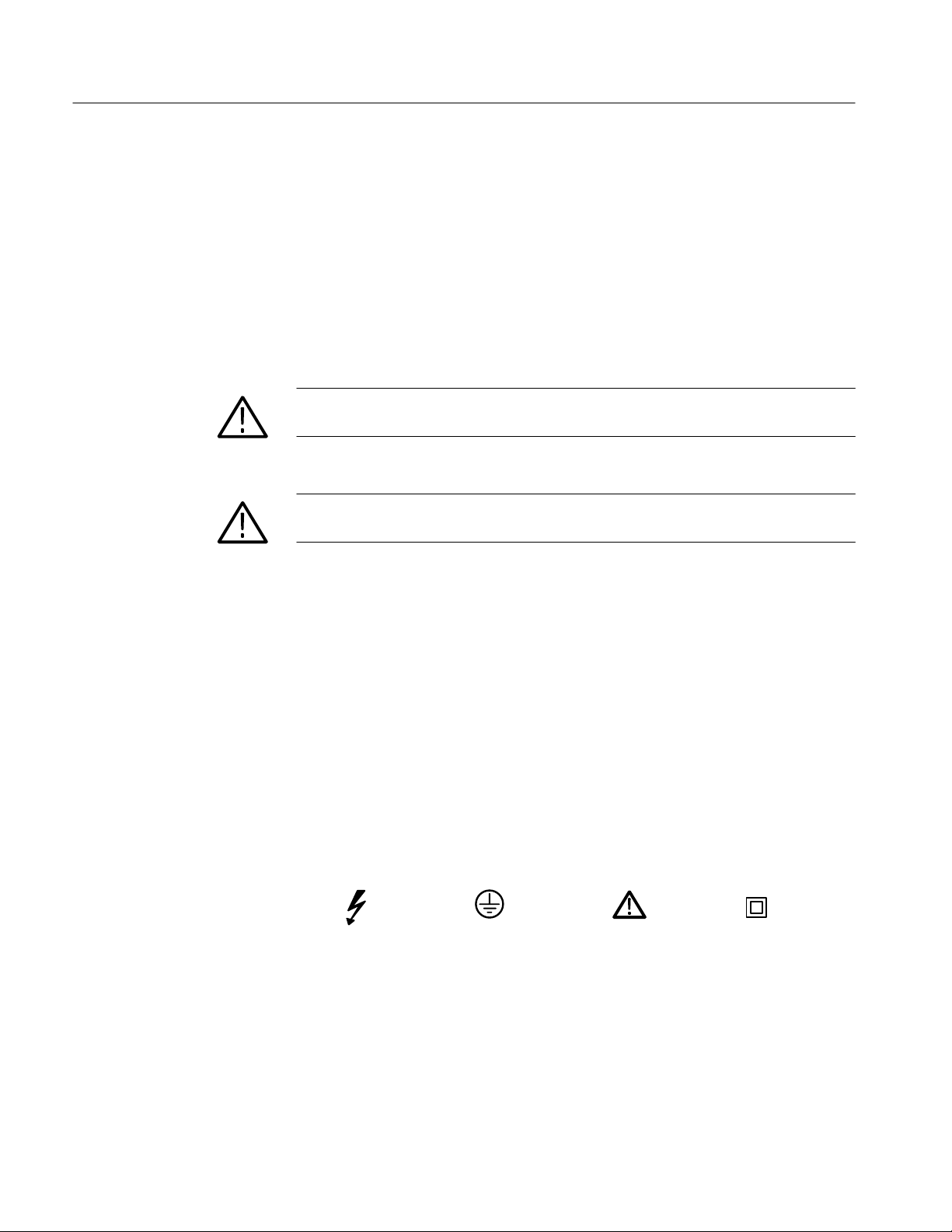
Warning
The servicing instructions are for use by qualified
personnel only. To avoi personal injury, do not
perform any servicing unless you are qualified to
do so. Refer to the Safety Summary prior to
performing service.
Page 2

Copyright T ektronix, Inc. 1992. All rights reserved.
T ektronix products are covered by U.S. and foreign patents, issued and pending. Information in this publication supercedes
that in all previously published material. Specifications and price change privileges reserved.
Printed in the U.S.A.
T ektronix, Inc., P.O. Box 1000, Wilsonville, OR 97070–1000
TEKTRONIX and TEK are registered trademarks of T ektronix, Inc.
Page 3

WARRANTY
T ektronix warrants that this product will be free from defects in materials and workmanship for a period of one (1) year
from the date of shipment. If any such product proves defective during this warranty period, T ektronix, at its option, either
will repair the defective product without charge for parts and labor, or will provide a replacement in exchange for the
defective product.
In order to obtain service under this warranty, Customer must notify Tektronix of the defect before the expiration of the
warranty period and make suitable arrangements for the performance of service. Customer shall be responsible for
packaging and shipping the defective product to the service center designated by T ektronix, with shipping charges prepaid.
T ektronix shall pay for the return of the product to Customer if the shipment is to a location within the country in which the
T ektronix service center is located. Customer shall be responsible for paying all shipping charges, duties, taxes, and any
other charges for products returned to any other locations.
This warranty shall not apply to any defect, failure or damage caused by improper use or improper or inadequate
maintenance and care. T ektronix shall not be obligated to furnish service under this warranty a) to repair damage resulting
from attempts by personnel other than T ektronix representatives to install, repair or service the product; b) to repair
damage resulting from improper use or connection to incompatible equipment; or c) to service a product that has been
modified or integrated with other products when the effect of such modification or integration increases the time or
difficulty of servicing the product.
THIS WARRANTY IS GIVEN BY TEKTRONIX WITH RESPECT TO THIS PRODUCT IN LIEU OF ANY
OTHER WARRANTIES, EXPRESSED OR IMPLIED. TEKTRONIX AND ITS VENDORS DISCLAIM ANY
IMPLIED WARRANTIES OF MERCHANTABILITY OR FITNESS FOR A PARTICULAR PURPOSE.
TEKTRONIX’ RESPONSIBILITY TO REPAIR OR REPLACE DEFECTIVE PRODUCTS IS THE SOLE AND
EXCLUSIVE REMEDY PROVIDED TO THE CUST OMER FOR BREACH OF THIS WARRANTY. TEKTRONIX
AND ITS VENDORS WILL NOT BE LIABLE FOR ANY INDIRECT , SPECIAL, INCIDENTAL, OR
CONSEQUENTIAL DAMAGES IRRESPECTIVE OF WHETHER TEKTRONIX OR THE VENDOR HAS
ADVANCE NOTICE OF THE POSSIBILITY OF SUCH DAMAGES.
Page 4

Page 5

Table of Contents
Specifications
Operating Information
Theory of Operation
General Safety Summary vii. . . . . . . . . . . . . . . . . . . . . . . . . . . . . . . . . . . .
Service Safety Summary xi. . . . . . . . . . . . . . . . . . . . . . . . . . . . . . . . . . . . .
Preface xiii. . . . . . . . . . . . . . . . . . . . . . . . . . . . . . . . . . . . . . . . . . . . . . . . . . .
Nominal Traits 1–1. . . . . . . . . . . . . . . . . . . . . . . . . . . . . . . . . . . . . . . . . . . . . . . . . . .
W arranted Characteristics 1–8. . . . . . . . . . . . . . . . . . . . . . . . . . . . . . . . . . . . . . . . . .
T ypical Characteristics 1–11. . . . . . . . . . . . . . . . . . . . . . . . . . . . . . . . . . . . . . . . . . . . .
Menu Selections 2–1. . . . . . . . . . . . . . . . . . . . . . . . . . . . . . . . . . . . . . . . . . . . . . . . . .
Resetting the HFS 9003 2–2. . . . . . . . . . . . . . . . . . . . . . . . . . . . . . . . . . . . . . . . . . . .
Setting the Time Base 2–3. . . . . . . . . . . . . . . . . . . . . . . . . . . . . . . . . . . . . . . . . . . . .
The RUN/STOP Button 2–4. . . . . . . . . . . . . . . . . . . . . . . . . . . . . . . . . . . . . . . . . . . .
The UNDO Button 2–4. . . . . . . . . . . . . . . . . . . . . . . . . . . . . . . . . . . . . . . . . . . . . . . .
Pulse Output 2–4. . . . . . . . . . . . . . . . . . . . . . . . . . . . . . . . . . . . . . . . . . . . . . . . . . . . .
Strap Settings 3–1. . . . . . . . . . . . . . . . . . . . . . . . . . . . . . . . . . . . . . . . . . . . . .
Module Descriptions 3–3. . . . . . . . . . . . . . . . . . . . . . . . . . . . . . . . . . . . . . . .
Mainframe 3–3. . . . . . . . . . . . . . . . . . . . . . . . . . . . . . . . . . . . . . . . . . . . . . . . . . . . . .
Backplane 3–3. . . . . . . . . . . . . . . . . . . . . . . . . . . . . . . . . . . . . . . . . . . . . . . . . . .
Power Supplies 3–3. . . . . . . . . . . . . . . . . . . . . . . . . . . . . . . . . . . . . . . . . . . . . . .
Fans 3–4. . . . . . . . . . . . . . . . . . . . . . . . . . . . . . . . . . . . . . . . . . . . . . . . . . . . . . . .
Front Panel Module 3–4. . . . . . . . . . . . . . . . . . . . . . . . . . . . . . . . . . . . . . . . . . . . . . .
Cards 3–4. . . . . . . . . . . . . . . . . . . . . . . . . . . . . . . . . . . . . . . . . . . . . . . . . . . . . . . . . .
CPU Card 3–4. . . . . . . . . . . . . . . . . . . . . . . . . . . . . . . . . . . . . . . . . . . . . . . . . . .
Time Base Card 3–4. . . . . . . . . . . . . . . . . . . . . . . . . . . . . . . . . . . . . . . . . . . . . . .
Pulse Generator Cards 3–5. . . . . . . . . . . . . . . . . . . . . . . . . . . . . . . . . . . . . . . . . .
Data Time Generator Cards 3–5. . . . . . . . . . . . . . . . . . . . . . . . . . . . . . . . . . . . .
Performance Verification
Required Test Equipment 4–1. . . . . . . . . . . . . . . . . . . . . . . . . . . . . . . . . . . . . . . . . . .
T est Record 4–2. . . . . . . . . . . . . . . . . . . . . . . . . . . . . . . . . . . . . . . . . . . . . . . . . . . . . .
Verification Sequence 4–11. . . . . . . . . . . . . . . . . . . . . . . . . . . . . . . . . . . . . . . . . . . . . .
Check Procedures 4–13. . . . . . . . . . . . . . . . . . . . . . . . . . . . . . . . . . . . . . . . . . . . . . . . .
HFS 9003 Service Manual
Self Test 4–11. . . . . . . . . . . . . . . . . . . . . . . . . . . . . . . . . . . . . . . . . . . . . . . . . . . .
Calibration 4–12. . . . . . . . . . . . . . . . . . . . . . . . . . . . . . . . . . . . . . . . . . . . . . . . . . .
i
Page 6

Table of Contents
Adjustment Procedures
Maintenance
Instrument Setup 4–13. . . . . . . . . . . . . . . . . . . . . . . . . . . . . . . . . . . . . . . . . . . . . .
Output Level Checks (HFS 9DG1 Card Only) 4–13. . . . . . . . . . . . . . . . . . . . . . .
Output Level Checks (HFS 9DG2 and HFS 9PG2 Cards Only) 4–16. . . . . . . . .
Output Level Checks (HFS 9PG1 Card Only) 4–19. . . . . . . . . . . . . . . . . . . . . . .
Trigger Output Level 4–21. . . . . . . . . . . . . . . . . . . . . . . . . . . . . . . . . . . . . . . . . .
Rise Time and Fall T ime Checks (HFS 9PG1 and HFS 9DG1 Cards Only) 4–22
Rise Time and Fall T ime Checks (HFS 9PG2 and HFS 9DG2 Cards Only) 4–25
Edge Placement Checks 4–27. . . . . . . . . . . . . . . . . . . . . . . . . . . . . . . . . . . . . . . .
Frequency Accuracy Check 4–31. . . . . . . . . . . . . . . . . . . . . . . . . . . . . . . . . . . . .
Phase Lock Check 4–34. . . . . . . . . . . . . . . . . . . . . . . . . . . . . . . . . . . . . . . . . . . . .
Required Test Equipment 5–1. . . . . . . . . . . . . . . . . . . . . . . . . . . . . . . . . . . . . . . . . . .
Disassembly for Adjustment 5–1. . . . . . . . . . . . . . . . . . . . . . . . . . . . . . . . . . . . . . . .
Adjustment 5–1. . . . . . . . . . . . . . . . . . . . . . . . . . . . . . . . . . . . . . . . . . . . . . . . . . . . . .
Preventive Maintenance 6–1. . . . . . . . . . . . . . . . . . . . . . . . . . . . . . . . . . . . .
Removal and Replacement 6–3. . . . . . . . . . . . . . . . . . . . . . . . . . . . . . . . . . .
Front Panel Module 6–3. . . . . . . . . . . . . . . . . . . . . . . . . . . . . . . . . . . . . . . . . . . . . . .
Cards 6–3. . . . . . . . . . . . . . . . . . . . . . . . . . . . . . . . . . . . . . . . . . . . . . . . . . . . . . . . . .
Mainframe Covers 6–4. . . . . . . . . . . . . . . . . . . . . . . . . . . . . . . . . . . . . . . . . . . . . . . .
Power Supply Assembly 6–5. . . . . . . . . . . . . . . . . . . . . . . . . . . . . . . . . . . . . . . . . . .
Power Supply Module: +5 V, +12 V, and –12 V 6–6. . . . . . . . . . . . . . . . . . . . . . . . .
Power Supply Module: –5.2 V, –2 V, and +24 V 6–7. . . . . . . . . . . . . . . . . . . . . . . . .
Backplane Secondary Fuses 6–8. . . . . . . . . . . . . . . . . . . . . . . . . . . . . . . . . . . . . . . . .
Backplane 6–9. . . . . . . . . . . . . . . . . . . . . . . . . . . . . . . . . . . . . . . . . . . . . . . . . . . . . . .
Fans 6–11. . . . . . . . . . . . . . . . . . . . . . . . . . . . . . . . . . . . . . . . . . . . . . . . . . . . . . . . . . .
ON/STANDBY Lamp 6–11. . . . . . . . . . . . . . . . . . . . . . . . . . . . . . . . . . . . . . . . . . . . .
ON/ST ANDBY Switch 6–12. . . . . . . . . . . . . . . . . . . . . . . . . . . . . . . . . . . . . . . . . . . .
Troubleshooting 6–13. . . . . . . . . . . . . . . . . . . . . . . . . . . . . . . . . . . . . . . . . . . .
Fuses 6–13. . . . . . . . . . . . . . . . . . . . . . . . . . . . . . . . . . . . . . . . . . . . . . . . . . . . . . . . . . .
Power Supply Modules 6–13. . . . . . . . . . . . . . . . . . . . . . . . . . . . . . . . . . . . . . . . . . . .
Electrical Noise 6–14. . . . . . . . . . . . . . . . . . . . . . . . . . . . . . . . . . . . . . . . . . . . . . . . . .
Fans 6–14. . . . . . . . . . . . . . . . . . . . . . . . . . . . . . . . . . . . . . . . . . . . . . . . . . . . . . . . . . .
Backplane Connectors 6–15. . . . . . . . . . . . . . . . . . . . . . . . . . . . . . . . . . . . . . . . . . . . .
Diagnostics 6–17. . . . . . . . . . . . . . . . . . . . . . . . . . . . . . . . . . . . . . . . . . . . . . . .
Power-On Diagnostics 6–17. . . . . . . . . . . . . . . . . . . . . . . . . . . . . . . . . . . . . . . . . . . . .
Self-Test Diagnostics 6–18. . . . . . . . . . . . . . . . . . . . . . . . . . . . . . . . . . . . . . . . . . . . . .
Calibration 6–18. . . . . . . . . . . . . . . . . . . . . . . . . . . . . . . . . . . . . . . . . . . . . . . . . . . . . .
Error Indications 6–19. . . . . . . . . . . . . . . . . . . . . . . . . . . . . . . . . . . . . . . . . . . . . . . . .
Diagnostic Procedure 6–22. . . . . . . . . . . . . . . . . . . . . . . . . . . . . . . . . . . . . . . . . . . . . .
Options
Electrical Parts List
ii
Options 7–1. . . . . . . . . . . . . . . . . . . . . . . . . . . . . . . . . . . . . . . . . . . . . . . . . . .
Electrical Parts List 8–1. . . . . . . . . . . . . . . . . . . . . . . . . . . . . . . . . . . . . . . . .
HFS 9003 Service Manual
Page 7

Diagrams
Mechanical Parts List
List of Figures
Table of Contents
Block Diagram 9–1. . . . . . . . . . . . . . . . . . . . . . . . . . . . . . . . . . . . . . . . . . . . .
Replaceable Parts List 10–1. . . . . . . . . . . . . . . . . . . . . . . . . . . . . . . . . . . . . . .
Parts Ordering Information 10–1. . . . . . . . . . . . . . . . . . . . . . . . . . . . . . . . . . . . . . . . .
Using the Replaceable Parts List 10–2. . . . . . . . . . . . . . . . . . . . . . . . . . . . . . . . . . . . .
Figure 2–1: HFS 9003 Mainframe and Front Panel 2–1. . . . . . . . . . . . . .
Figure 2–2: MAIN MENU, SELECT, and Arrow Button Locations 2–2.
Figure 2–3: Main Menu Display 2–2. . . . . . . . . . . . . . . . . . . . . . . . . . . . . .
Figure 2–4: The Time Base Menu 2–3. . . . . . . . . . . . . . . . . . . . . . . . . . . . .
Figure 2–5: Mode set to Auto-Burst 2–3. . . . . . . . . . . . . . . . . . . . . . . . . . .
Figure 2–6: Controls and Connectors for the Pulse, Data Time
Generator, and Time Base Cards 2–5. . . . . . . . . . . . . . . . . . . . . . . . . .
Figure 3–1: Backplane Jumper Settings and Connections 3–2. . . . . . . . .
Figure 5–1: Rear Power Supply Voltage and Adjustment Locations 5–2.
Figure 5–2: Front Power Supply Voltage and Adjustment Locations 5–2
Figure 6–1: Clock Distribution Cable Location 6–4. . . . . . . . . . . . . . . . . .
Figure 6–2: Backplane Jumper Settings 6–10. . . . . . . . . . . . . . . . . . . . . . . .
Figure 6–3: The Location of LEDs on the CPU Card 6–20. . . . . . . . . . . . .
Figure 6–4: Bit Assignments for Diagnostic LEDs 6–21. . . . . . . . . . . . . . . .
Figure 6–5: Diagnostic Procedure Flowchart 6–24. . . . . . . . . . . . . . . . . . . .
Figure 9–1: Module Block and Interconnection Diagram 9–2. . . . . . . . . .
Figure 10–1: Front Panel 10–5. . . . . . . . . . . . . . . . . . . . . . . . . . . . . . . . . . . .
Figure 10–2: Rear Panel and Power Supply 10–7. . . . . . . . . . . . . . . . . . . . .
Figure 10–3: Circuit Boards and Fan Assembly 10–9. . . . . . . . . . . . . . . . .
Figure 10–4: Chassis and Covers 10–11. . . . . . . . . . . . . . . . . . . . . . . . . . . . . .
HFS 9003 Service Manual
iii
Page 8

Table of Contents
List of Tables
Table 1–1: Nominal Traits — HFS 9PG1 Output Performance 1–1. . . .
Table 1–2: Nominal Traits — HFS 9PG2 Output Performance 1–2. . . .
Table 1–3: Nominal Traits — HFS 9DG1 Output Performance 1–3. . . .
Table 1–4: Nominal Traits — HFS 9DG2 Output Performance 1–3. . . .
Table 1–5: Nominal Traits — Time Base 1–4. . . . . . . . . . . . . . . . . . . . . . .
Table 1–6: Nominal Traits — Performance to External Frequency
Reference 1–4. . . . . . . . . . . . . . . . . . . . . . . . . . . . . . . . . . . . . . . . . . . . .
Table 1–7: Nominal Traits — Output Edge Placement Performance 1–5
Table 1–8: Nominal Traits — Transducer In Performance 1–5. . . . . . . .
Table 1–9: Nominal Traits — Skew Cal In Performance 1–5. . . . . . . . . .
Table 1–10: Nominal Traits — Trigger In Performance 1–6. . . . . . . . . . .
Table 1–11: Nominal Traits — Trigger Out Performance 1–6. . . . . . . . .
Table 1–12: Nominal Traits — Power Requirements 1–6. . . . . . . . . . . . .
Table 1–13: Nominal Traits — System Memory Performance 1–6. . . . .
Table 1–14: Nominal Traits — HFS 9003 Mechanical 1–7. . . . . . . . . . . .
Table 1–15: Nominal Traits — HFS 9009 Mechanical 1–7. . . . . . . . . . . .
Table 1–16: Warranted Characteristics — HFS 9PG1 Output
Performance 1–8. . . . . . . . . . . . . . . . . . . . . . . . . . . . . . . . . . . . . . . . . . .
Table 1–17: Warranted Characteristics — HFS 9PG2 Output
Performance 1–8. . . . . . . . . . . . . . . . . . . . . . . . . . . . . . . . . . . . . . . . . . .
Table 1–18: Warranted Characteristics — HFS 9DG1 Output
Performance 1–8. . . . . . . . . . . . . . . . . . . . . . . . . . . . . . . . . . . . . . . . . . .
Table 1–19: Warranted Characteristics — HFS 9DG2 Output
Performance 1–9. . . . . . . . . . . . . . . . . . . . . . . . . . . . . . . . . . . . . . . . . . .
Table 1–20: Warranted Characteristics — Time Base 1–9. . . . . . . . . . . .
Table 1–21: Warranted Characteristic — Performance to External
Frequency Reference 1–9. . . . . . . . . . . . . . . . . . . . . . . . . . . . . . . . . . . .
Table 1–22: Warranted Characteristics — Output Edge Placement
Performance 1–9. . . . . . . . . . . . . . . . . . . . . . . . . . . . . . . . . . . . . . . . . . .
Table 1–23: Warranted Characteristics — Trigger Out Performance 1–10
Table 1–24: Warranted Characteristics — Power Requirements 1–10. . .
Table 1–25: Warranted Characteristics — Environmental and
Safety 1–10. . . . . . . . . . . . . . . . . . . . . . . . . . . . . . . . . . . . . . . . . . . . . . . . .
Table 1–26: Typical Characteristics — Time Base 1–11. . . . . . . . . . . . . . .
Table 1–27: Typical Characteristics — HFS 9PG1 Output
Performance 1–11. . . . . . . . . . . . . . . . . . . . . . . . . . . . . . . . . . . . . . . . . . .
iv
HFS 9003 Service Manual
Page 9

Table of Contents
Table 1–28: Typical Characteristics — HFS 9PG2 Output
Performance 1–12. . . . . . . . . . . . . . . . . . . . . . . . . . . . . . . . . . . . . . . . . . .
Table 1–29: Typical Characteristics — HFS 9DG1 Output
Performance 1–12. . . . . . . . . . . . . . . . . . . . . . . . . . . . . . . . . . . . . . . . . . .
Table 1–30: Typical Characteristics — HFS 9DG2 Output
Performance 1–12. . . . . . . . . . . . . . . . . . . . . . . . . . . . . . . . . . . . . . . . . . .
Table 1–31: Typical Characteristics — Performance to External
Frequency Reference 1–13. . . . . . . . . . . . . . . . . . . . . . . . . . . . . . . . . . . .
Table 1–32: Typical Characteristics — Transducer In Performance 1–13
Table 1–33: Typical Characteristics — Trigger In Performance 1–13. . . .
Table 1–34: Typical Characteristics — Trigger Out Performance 1–14. .
Table 1–35: Typical Characteristics — Power Requirements 1–14. . . . . .
Table 4–1: Required Test Equipment 4–1. . . . . . . . . . . . . . . . . . . . . . . . . .
Table 4–2: Trigger Output Level and Phase Lock Test 4–3. . . . . . . . . . . .
Table 4–3: Test Record for HFS 9DG1 Card 4–4. . . . . . . . . . . . . . . . . . . .
Table 4–4: Test Record for HFS 9DG2 Card 4–6. . . . . . . . . . . . . . . . . . . .
Table 4–5: Test Record for HFS 9PG1 Card 4–7. . . . . . . . . . . . . . . . . . . .
Table 4–6: Test Record for HFS 9PG2 Card 4–9. . . . . . . . . . . . . . . . . . . .
Table 4–7: HFS 9DG1 Output Level Checks, First Settings 4–14. . . . . . .
Table 4–8: HFS 9DG1 Output Level Checks, Second Settings 4–14. . . . .
Table 4–9: HFS 9DG1 Output Level Checks, Third Settings 4–15. . . . . . .
Table 4–10: HFS 9DG1 Output Level Checks, Fourth Settings 4–15. . . . .
Table 4–11: HFS 9DG2 and HFS 9PG2 Output Level Checks,
First Settings 4–17. . . . . . . . . . . . . . . . . . . . . . . . . . . . . . . . . . . . . . . . . . .
Table 4–12: HFS 9DG2 and HFS 9PG2 Output Level Checks, Second
Settings 4–17. . . . . . . . . . . . . . . . . . . . . . . . . . . . . . . . . . . . . . . . . . . . . . .
Table 4–13: HFS 9PG2 Output Level Checks, Third Settings 4–18. . . . . .
Table 4–14: HFS 9PG2 Output Level Checks, Fourth Settings 4–18. . . . .
Table 4–15: HFS 9PG1 Output Level Checks, First Settings 4–19. . . . . . .
Table 4–16: HFS 9PG1 Output Level Checks, Second Settings 4–20. . . . .
Table 4–17: HFS 9PG1 Output Level Checks, Third Settings 4–20. . . . . .
Table 4–18: HFS 9PG1 Output Level Checks, Fourth Settings 4–21. . . . .
Table 4–19: Settings for Trigger Output Check 4–22. . . . . . . . . . . . . . . . .
Table 4–20: Settings for Rise Time and Fall Time Checks 4–23. . . . . . . . .
Table 4–21: DSO Settings for Rise/Fall Time Checks 4–24. . . . . . . . . . . . .
Table 4–22: Settings for Rise Time and Fall Time Checks 4–25. . . . . . . . .
Table 4–23: DSO Settings for Rise/Fall Time Checks 4–26. . . . . . . . . . . . .
Table 4–24: Settings for Edge Placement Checks 4–27. . . . . . . . . . . . . . . .
Table 4–25: Lead Delay Limits for HFS 9PG1 and HFS 9PG2 4–28. . . . .
Table 4–26: Lead Delay Limits for HFS 9DG1 and HFS 9DG2 4–29. . . .
HFS 9003 Service Manual
v
Page 10

Table of Contents
Table 4–27: Width Variance Limits for HFS 9PG1 4–29. . . . . . . . . . . . . . .
Table 4–28: Width Variance Limits for HFS 9DG1 4–30. . . . . . . . . . . . . .
Table 4–29: Width Limits for HFS 9PG1 and HFS 9PG2 4–30. . . . . . . . .
Table 4–30: Width Limits for HFS 9DG1 4–30. . . . . . . . . . . . . . . . . . . . . .
Table 4–31: Width Limits for HFS 9DG2 4–31. . . . . . . . . . . . . . . . . . . . . .
Table 4–32: Frequency Limits (HFS 9PG1 & HFS 9DG1) 4–32. . . . . . . . .
Table 4–33: Frequency Limits (HFS 9PG2) 4–32. . . . . . . . . . . . . . . . . . . . .
Table 4–34: Frequency Limits (HFS 9DG2) 4–33. . . . . . . . . . . . . . . . . . . .
Table 5–1: Power Supply Tolerances 5–2. . . . . . . . . . . . . . . . . . . . . . . . . .
Table 6–1: Results from *TST? 6–18. . . . . . . . . . . . . . . . . . . . . . . . . . . . . . .
Table 6–2: Troubleshooting From the Error Index Code 6–22. . . . . . . . . .
vi
HFS 9003 Service Manual
Page 11

General Safety Summary
Review the following safety precautions to avoid injury and prevent damage to
this product or any products connected to it.
Only qualified personnel should perform service procedures.
Injury Precautions
Use Proper Power Cord
Avoid Electric Overload
Ground the Product
Do Not Operate Without
Covers
Use Proper Fuse
Do Not Operate in
Wet/Damp Conditions
Do Not Operate in
Explosive Atmosphere
To avoid fire hazard, use only the power cord specified for this product.
To avoid electric shock or fire hazard, do not apply a voltage to a terminal that is
outside the range specified for that terminal.
This product is grounded through the grounding conductor of the power cord. To
avoid electric shock, the grounding conductor must be connected to earth
ground. Before making connections to the input or output terminals of the
product, ensure that the product is properly grounded.
To avoid electric shock or fire hazard, do not operate this product with covers or
panels removed.
To avoid fire hazard, use only the fuse type and rating specified for this product.
To avoid electric shock, do not operate this product in wet or damp conditions.
To avoid injury or fire hazard, do not operate this product in an explosive
atmosphere.
Product Damage Precautions
Use Proper Power Source
Provide Proper Ventilation
HFS 9003 Service Manual
Do not operate this product from a power source that applies more than the
voltage specified.
To prevent product overheating, provide proper ventilation.
vii
Page 12
General Safety Summary
Do Not Operate With
Suspected Failures
If you suspect there is damage to this product, have it inspected by qualified
service personnel.
Safety Terms and Symbols
Terms in This Manual
Terms on the Product
These terms may appear in this manual:
WARNING. Warning statements identify conditions or practices that could result
in injury or loss of life.
CAUTION. Caution statements identify conditions or practices that could result in
damage to this product or other property.
These terms may appear on the product:
Symbols on the Product
DANGER indicates an injury hazard immediately accessible as you read the
marking.
WARNING indicates an injury hazard not immediately accessible as you read the
marking.
CAUTION indicates a hazard to property including the product.
The following symbols may appear on the product:
DANGER
High Voltage
Protective Ground
(Earth) T erminal
ATTENTION
Refer to
Manual
Double
Insulated
viii
HFS 9003 Service Manual
Page 13

Certifications and Compliances
General Safety Summary
CSA Certified Power
Cords
Compliances
CSA Certification includes the products and power cords appropriate for use in
the North America power network. All other power cords supplied are approved
for the country of use.
Consult the product specifications for IEC Installation Category, Pollution
Degree, and Safety Class.
HFS 9003 Service Manual
ix
Page 14

General Safety Summary
x
HFS 9003 Service Manual
Page 15

Service Safety Summary
Only qualified personnel should perform service procedures. Read this Service
Safety Summary and the General Safety Summary before performing any service
procedures.
Do Not Service Alone
Disconnect Power
Use Care When Servicing
With Power On
Do not perform internal service or adjustments of this product unless another
person capable of rendering first aid and resuscitation is present.
To avoid electric shock, disconnect the main power by means of the power cord
or, if provided, the power switch.
Dangerous voltages or currents may exist in this product. Disconnect power,
remove battery (if applicable), and disconnect test leads before removing
protective panels, soldering, or replacing components.
To avoid electric shock, do not touch exposed connections.
HFS 9003 Service Manual
xi
Page 16

Service Safety Summary
xii
HFS 9003 Service Manual
Page 17

Preface
This Service Manual provides you with limited service information for the
HFS 9003 Stimulus System.
H The Specifications section contains all nominal, typical, and specified
characteristics.
H The Operating Information section teaches you about each of the front panel
controls and how to input simple settings for basic operation.
H The Theory of Operation section helps you understand the operation of each
of the replaceable modules in the HFS 9003.
H The Performance Verification section gives you procedures on how to verify
the specified performance of the instrument.
H The Adjustment Procedures section lists the adjustments you can make to the
instrument.
H The Maintenance section instructs you on how to perform general preventive
maintenance on the instrument. This section also describes removal,
replacement and troubleshooting procedures.
Notation Conventions
H The Options section lists the options available from the factory. This section
also describes the procedure for installing field updates to the internal
programmed code of the instrument.
H The Diagrams section describes and illustrates the major electrical sections
of the HFS 9003.
H The Mechanical Parts List section lists all of the replaceable parts and
describes how to order these parts.
The following conventions are used in this manual:
H Signal names are printed in bold capital letters; for example, SENSE IN.
H A signal active in the low state is shown with a tilde (~) in front of the signal
name; for example, ~ACFAIL.
H Labels of front panel buttons and connectors are shown in bold capital
letters; for example, ENTER.
H Labels of menu items are shown in mixed case bold text; for example, the
Pulse menu Amplitude item.
HFS 9003 Service Manual
xiii
Page 18

Preface
Related Manuals
Refer to the HFS 9000 User Manual (070-8365-01) for additional operating
information.
xiv
HFS 9003 Service Manual
Page 19

Page 20
Specifications
Nominal Traits
The HFS 9000 family of high-speed logic signal source instruments have a
modular architecture with factory-configurable cards. The channels are digitally
synthesized from a common clock resulting in highly accurate independent
placement of rising and falling edges. The instruments are optimized for digital
device characterization with unique triggering capabilities and a variety of pulse
outputs. The product family also features low RMS jitter, the ability to compensate for external cable skews, and an easy-to-use graphical human interface.
This section contains the complete specifications for the HFS 9000 Stimulus
System and Modules. These specifications are classified as either nominal traits,
warranted characteristics, or typical characteristics.
Nominal traits are described using simple statements of fact such as “+2.6 V” for
the trait “Maximum high level,” rather than in terms of limits that are performance requirements.
T able 1–1: Nominal Traits — HFS 9PG1 Output Performance
Each channel and complement driving a 50 load to ground, except as noted.
Name
Maximum high level +2.6 V
Minimum low level –2.00 V
Maximum amplitude 3.00 V
Minimum amplitude 0.50 V
Level resolution 0.01 V
Operation when terminated
through 50 to –2 V
Description
Output levels will be approximately 1 V more negative than
the values programmed, specified, and displayed. Actual
output levels more negative than –2 V may cause
malfunction. Level accuracy specifications do not apply
when terminating to –2 V. Both true and complement
outputs must be terminated to the same voltage.
HFS 9003 Service Manual
1–1
Page 21
Specifications
T able 1–1: Nominal Traits — HFS 9PG1 Output Performance (Cont.)
Each channel and complement driving a 50 load to ground, except as noted.
Name Description
Operation when terminated to
high impedance loads
Output limits One high limit and one low limit may be enabled or disabled
Output level range will double until certain internal limits are
achieved. Since the programmed, specified, and displayed
output levels do not match the actual output levels, level
accuracy specifications do not apply when terminating to a
high impedance load. Because of the larger voltage swings
associated with doubled level range, output transition time
specifications do not apply when driving a high impedance
load.
together.
T able 1–2: Nominal Traits — HFS 9PG2 Output Performance
Each channel and complement driving a 50 load to ground, except as noted.
Name
Maximum high level +5.50 V
Minimum low level –2.00 V
Maximum amplitude 5.50 V
Minimum amplitude 0.50 V
Level resolution 0.01 V
Operation when terminated
through 50 to –2 V
Transition time 20% to 80% V ariable from 800 ps to 5 ns
Transition time resolution 10 ps
Output limits One high limit and one low limit may be enabled or disabled
Description
Output levels will be approximately 1 V more negative than
the values programmed, specified, and displayed. Actual
output levels more negative than –2 V may cause
malfunction. Level accuracy specifications do not apply
when terminating to –2 V. Both true and complement
outputs must be terminated to the same voltage.
together.
1–2
HFS 9003 Service Manual
Page 22
T able 1–3: Nominal Traits — HFS 9DG1 Output Performance
Each channel and complement driving a 50 load to ground, except as noted.
Specifications
Name
Maximum high level +5.0V
Minimum low level –2.5 V
Maximum amplitude 3.00 V
Minimum amplitude 0.01 V
Level resolution 0.01V
Operation when terminated
through 50 to –2 V
Operation when terminated to
high impedance loads
Output limits One high limit and one low limit may be enabled or
Description
Output levels will be approximately 1 V more negative than
the values programmed, specified, and displayed. Actual
output levels more negative than –2 V may cause
malfunction. Level accuracy specifications do not apply
when terminating to –2 V. Both true and complement
outputs must be terminated to the same voltage.
Output level range will double until certain internal limits
are achieved. Since the programmed, specified, and
displayed output levels do not match the actual output
levels, level accuracy specifications do not apply when
terminating to a high impedance load. Because of the
larger voltage swings associated with doubled level range,
output transition time specifications do not apply when
driving a high impedance load.
disabled together.
HFS 9003 Service Manual
T able 1–4: Nominal Traits — HFS 9DG2 Output Performance
Each channel and complement driving a 50 load to ground, except as noted.
Name
Maximum high level +5.50 V
Minimum low level –2.00 V
Maximum amplitude 5.50 V
Minimum amplitude 0.01 V
Level resolution 0.01 V
Operation when terminated
through 50 to –2 V
Transition time 20% to 80% V ariable from 800 ps to 6 ns
Description
Output levels will be approximately 1 V more negative than
the values programmed, specified, and displayed. Actual
output levels more negative than –2 V may cause
malfunction. Level accuracy specifications do not apply
when terminating to –2 V. Both true and complement
outputs must be terminated to the same voltage.
1–3
Page 23
Specifications
T able 1–4: Nominal Traits — HFS 9DG2 Output Performance (Cont.)
Each channel and complement driving a 50 W load to ground, except as noted.
Name Description
Transition time resolution 10 ps
Output limits One high limit and one low limit may be enabled or disabled
together.
T able 1–5: Nominal Traits — Time Base
Name Description
Frequency range HFS 9PG1, HFS 9DG1: 50 kHz to 630MHz
HFS 9PG2, HFS 9DG2: 50 kHz to 300 MHz
Frequency resolution ≤ 0.1% of frequency setting
1
Minimum frequency setting when
using half, quarter, or eighth
pulse rate modes
2
Number of pulse periods in burst
half pulse rate: 100 kHz
quarter pulse rate: 200 kHz
eighth pulse rate: 400 kHz
User selectable from 1 to 65,536
or auto-burst modes
1
If the HFS 9PG2 or HFS 9DG2 is operated in half pulse rate mode, frequency can be
extended to 600 MHz for the HFS 9PG2 and 630 MHz for the HFS 9DG2.
2
All pulse rate modes result in 50 kHz output frequency.
T able 1–6: Nominal Traits — Performance to External Frequency Reference
Name Description
PHASE LOCK IN input charac-
teristic
Phase lock output frequency
range
FRAME SYNC IN Initiates a burst when using phase lock mode
FRAME SYNC IN input charac-
teristic
0.1 mF DC blocking capacitor followed by 50W termination
to ground
Any 2n multiple or sub-multiple of the phase lock frequency
that is within the allowed frequency range for the card being
used
50 W terminated to –2V
1–4
HFS 9003 Service Manual
Page 24

T able 1–7: Nominal Traits — Output Edge Placement Performance1
Name Description
Channel deskew (Chan Delay)
range, channels relative to time
zero reference
Channel deskew (Chan Delay)
resolution
–60 ns to 2.0ms
HFS 9PG1, HFS 9PG2: 5 ps
HFS 9DG1, HFS 9DG2: 1 ps
Specifications
Delay (Lead Delay) adjustment
range
Delay (Lead Delay, Trail Delay)
adjustment resolution
Pulse width adjustment range HFS 9PG1, HFS 9PG2: Zero to (one period – 790 ps)
Pulse width adjustment resolution
Fine knob resolution of timing 5 ps
1
Measured at 50% levels, each channel independent.
Zero to 20 ms
HFS 9PG1, HFS 9PG2: 5 ps
HFS 9DG1, HFS 9DG2: 1 ps
inclusive
HFS 9DG1, HFS 9DG2: Zero to (one period × 65,536)
inclusive
HFS 9PG1, HFS 9PG2: 5 ps
HFS 9DG1, HFS 9DG2: 1 ps
T able 1–8: Nominal Traits — Transducer In Performance
Name Description
TRANSDUCER IN input charac-
teristic
HFS 9PG1: 1000 pF DC blocking capacitor followed by
50 W termination to ground
HFS 9PG2: 100 pF DC blocking capacitor followed by 50W
termination to ground
HFS 9003 Service Manual
T able 1–9: Nominal Traits — Skew Cal In Performance
Name Description
SKEW CAL IN usage Calibration use only . No signal, except from a channel
OUTPUT connector during the calibration process, should
ever be applied to this input.
1–5
Page 25
Specifications
1
T able 1–10: Nominal Traits — Trigger In Performance
Name Description
Input Voltage range ±5 V maximum
Trigger level range ±4.70 V
Trigger level resolution 100 mV
T able 1–11: Nominal Traits — Trigger Out Performance
Name Description
Pretrigger range, TRIGGER OUT
before time zero reference
TRIGGER OUT pulse width in
auto mode
Zero to 70 ns
00
10
Width
(ns)
1
0.1
0.01 0.1 1 10 100 1000
Output Frequency (MHz)
T able 1–12: Nominal Traits — Power Requirements
Name HFS 9003 Description HFS 9009 Description
Fuse ratings 5 A, 250V, type 3AG,
(Tektronix part 159-0014-00),
and
15 A, 250V, type 3AG, fast
blow, (Tektronix part
159-0256-00)
4 A, 250V, type 3AG, fast
blow, (Tektronix part
159-0017-00)
T able 1–13: Nominal Traits — System Memory Performance
Name Description
Non-volatile memory retention
time
Instrument settings and calibration constants are retained
in non-volatile memory for 5 years or more. Card
identification is retained for 10 years. Extended storage
above 50_ C may degrade the life of all non-volatile
memory .
1–6
HFS 9003 Service Manual
Page 26

Specifications
T able 1–14: Nominal Traits — HFS 9003 Mechanical
Name Description
Weight, in 12-channel configuration. (Shipping weight includes all
standard accessories.)
Overall Dimensions Cabinet Rackmount
Cooling Method Forced-air circulation with no air filter, maximum 318 cfm
Construction Material Chassis parts are constructed of aluminum alloy; bezel is
Net weight: 45 lbs. (20.5 kg) 51 lbs. (23.2 kg)
Shipping weight: 60 lbs. (27.3 kg) 66 lbs. (30.0 kg)
Width: 16.3 in. (414 mm) 19.0 in (483 mm)
Height: 7.0 in. (178 mm) 7.0 in. (178 mm)
Depth: 24.75 in. (629 mm) 24.75 in. (629 mm)
Depth behind
rack flange: — 22.0 in. (559 mm)
glass-filled polycarbonate with Lexan plastic inserts; cabinet
is aluminum with textured epoxy paint.
Cabinet Rackmount
T able 1–15: Nominal Traits — HFS 9009 Mechanical
Name Description
Weight, in 36-channel configuration. (Shipping weight includes all
standard accessories.)
Overall Dimensions Rackmount
Cooling Method, mainframe Forced-air circulation with air filter, maximum 318 cfm
Cooling Method, power supply Forced-air circulation, maximum 106 cfm
Construction Material Chassis parts are constructed of aluminum alloy with Lexan
Net weight: 81 lbs. (33.7 kg)
Shipping weight: 100 lbs. (45.3 kg)
Width: 16.75 in (425.79 mm)
Height: 14.00 in. (355.89 mm)
Depth: 24.00 in. (610.11 mm)
plastic inserts; cabinet is aluminum with textured epoxy
paint.
Rackmount
HFS 9003 Service Manual
1–7
Page 27
Specifications
Warranted Characteristics
Warranted characteristics are described in terms of quantifiable performance
limits which are warranted. Names of characteristics that appear in boldface type
have checks for verifying the specifications in the Check Procedures section.
T able 1–16: Warranted Characteristics — HFS 9PG1 Output Performance
Name Description
High level accuracy (amplitude
≥ 1 V or high level ≥ 0 V)
1
±2% of level, ±50 mV
Low level accuracy (amplitude
≥ 1 V or high level ≥ 0 V)
Transition time 20% to 80%
(amplitude ≤ 1V)
1
If amplitude < 1 V and high level < 0 V, accuracy typically meets the specification but
is not guaranteed
1
±2% of high level, ±2% of amplitude, ±50 mV
≤ 200ps
T able 1–17: Warranted Characteristics — HFS 9PG2 Output Performance
Name Description
High level accuracy ±2% of level, ±50 mV
Low level accuracy ±2% of high level, ±2% of amplitude, ±50 mV
Transition time accuracy 20%
to 80% (amplitude ≤ 1V)
±10% of setting, ±300 ps
T able 1–18: Warranted Characteristics — HFS 9DG1 Output Performance
Name Description
High level accuracy (amplitude
1
≥ 0.5 V)
±2% of level, ±50 mV
1–8
Low level accuracy (amplitude
1
≥ 0.5 V)
Transition time 20% to 80%
(amplitude ≤ 1V)
1
If amplitude < 0.5 V , accuracy typically meets the specification but is not guaranteed
±2% of high level, ±2% of amplitude, ±50 mV
≤ 250ps
HFS 9003 Service Manual
Page 28
Specifications
T able 1–19: Warranted Characteristics — HFS 9DG2 Output Performance
Name Description
High level accuracy (amplitude
1
≥ 0.5 V)
±2% of level, ±50 mV
Low level accuracy (amplitude
1
≥ 0.5 V)
Transition time accuracy 20%
±2% of high level, ±2% of amplitude, ±50 mV
±10% of setting, ±300 ps
to 80% (amplitude ≤ 1V)
1
If amplitude < 0.5 V , accuracy typically meets the specification but is not guaranteed.
T able 1–20: Warranted Characteristics — Time Base
Name Description
Frequency accuracy ±1%
T able 1–21: Warranted Characteristic — Performance to External Frequency
Reference
Name Description
PHASE LOCK IN frequency
range
6 MHz to 630 MHz
HFS 9003 Service Manual
T able 1–22: Warranted Characteristics — Output Edge Placement
Performance
Name Description
Delay of pulses relative to time
zero reference (Lead Delay)
accuracy
Pulse width accuracy HFS 9PG1: 1% of width ±300 ps
1
Measured at 50% levels, each channel independent.
1
HFS 9PG1, HFS 9PG2: 1% of (Lead Delay + Chan Delay)
±300 ps
HFS 9DG1, HFS 9DG2: 1% of (Lead Delay + Chan Delay)
±50 ps
HFS 9PG2: 1% of width ±300 ps [for widths 20 ns]; 1%
of width300 ps, –500 ps [for widths 20 ns]
HFS 9DG1: 1% of width 50 –75 ps
HFS 9DG2: 1% of width50 ps, –250 ps [for widths
20 ns]; 1% of width50 ps, –450 ps [for widths
20 ns]
1–9
Page 29
Specifications
T able 1–23: Warranted Characteristics — Trigger Out Performance
Name Description
TRIGGER OUT signal levels Amplitude ≥ 300 mV (–0.5 V ≥ offset ≥ –1.5 V, driving 50
to ground)
T able 1–24: Warranted Characteristics — Power Requirements
Name Description
Primary circuit dielectric breakdown voltage
Primary Grounding 0.1 maximum from chassis ground and protective earth
1500 VAC
ground
, 60 Hz for 10 seconds without breakdown
RMS
T able 1–25: Warranted Characteristics — Environmental and Safety
Name HFS 9003 Description HFS 9009 Description
Temperature Operating: 0_ C to +50_ C
(32_ F to 122_ F)
Non-operating (storage):
–40_ C to +75_ C (–40_ F
to 167_ F)
Altitude Operating: 4 hours at 3,048 m (10,000 feet). Derate
maximum operating temperature by –1_ C (–1.8_ F) for
each 304.8 m (1,000 feet) above 1,524 m (5,000 feet)
Non-operating: 2 hours at 12,192 m (40,000 feet)
Humidity Operating: 95% RH, non-condensing, from 0_ C to
30_ C (32_ F to 86_ F)
75% RH, non-condensing, from 31_ C to 40_ C (88_ F
to 104_ F)
(MIL-T-28800E, para 4.5.5.1.2.2, Type III, Class 5)
Shock (non-operating) MIL-T-28800E, para 4.5.5.4.1, Type III, Class 5
Resistance to mishandling during
bench use (operating)
Resistance to packaged trans-
portation vibration, sinusoidal, in
shipping package
Resistance to packaged transportation vibration, sinusoidal, in
shipping package
Resistance to packaged transportation random vibration
MIL-T-28800E, para 4.5.5.4.3, Type III, Class 5
Drops of 36 inches on all edges, faces, and corners
National Safe Transit Association, test procedure 1A-B-2
Packaged sinusoidal vibration
National Safe Transit Association, test procedure 1A-B-1
MIL-STD-810D, method 514.3, category I, Figure 514.3-1
Operating: 0_ C to +40_ C
(32_ F to 104_ F)
Non-operating (storage):
–40_ C to +75_ C (–40_ F
to 167_ F)
1–10
HFS 9003 Service Manual
Page 30
Typical Characteristics
Specifications
T able 1–25: Warranted Characteristics — Environmental and Safety (Cont.)
Name HFS 9009 DescriptionHFS 9003 Description
Safety Listed to UL1244
Certified to CAN/CSA-C22.2 No. 231–M89
IEC Specifications Installation Category II
Pollution Degree 2
Safety Class I
Typical characteristics are described in terms of typical or average performance.
Typical characteristics are not warranted.
T able 1–26: Typical Characteristics — Time Base
Name Description
RMS jitter 15 ps, ±0.05% of interval
Recovery time between bursts or
auto-bursts
15 ms
T able 1–27: Typical Characteristics — HFS 9PG1 Output Performance
Name Description
Transition time 20% to 80% Amplitude ≤ 1 V: 150 ps
1 V < Amplitude ≤ 2 V: 190 ps
2 V < Amplitude ≤ 3 V: 225 ps
Output aberrations (beginning
200 ps after 50% point of transition)
Overshoot: +15%, +20 mV
Undershoot: –10%, –20 mV
HFS 9003 Service Manual
1–11
Page 31

Specifications
T able 1–28: Typical Characteristics — HFS 9PG2 Output Performance
Name Description
Operation when terminated to
high impedance loads
Output level range will double until certain internal limits are
achieved. Since the programmed, specified, and displayed
output levels do not match the actual output levels, level
accuracy specifications do not apply when terminating to a
high impedance load. Because of the larger voltage swings
associated with doubled level range, output transition time
specifications do not apply when driving a high impedance
load.
Transition time accuracy 20% to
80%
Output aberrations Overshoot: +15%, +20 mV
±10% of setting, ±300 ps
Undershoot: –10%, –20 mV
T able 1–29: Typical Characteristics — HFS 9DG1 Output Performance
Name Description
Transition time 20% to 80% Amplitude ≤ 1V: ≤ 250 ps, 250 ps
1 V < Amplitude < 2 V: 250 ps
2V ≤ Amplitude ≤ 3 V: 260ps
Output aberrations Overshoot: +15%, +20 mV
Undershoot: –10%, –20 mV
T able 1–30: Typical Characteristics — HFS 9DG2 Output Performance
Name Description
Operation when terminated to
high impedance loads
Output level range will double until certain internal limits are
achieved. Since the programmed, specified, and displayed
output levels do not match the actual output levels, level
accuracy specifications do not apply when terminating to a
high impedance load. Because of the larger voltage swings
associated with doubled level range, output transition time
specifications do not apply when driving a high impedance
load.
1–12
Transition time accuracy 20% to
80%
Output aberrations Overshoot: +15%, +20 mV
±10% of setting, ±300 ps
Undershoot: –10%, –20 mV
HFS 9003 Service Manual
Page 32

Specifications
T able 1–31: Typical Characteristics — Performance to External Frequency
Reference
Name Description
PHASE LOCK IN amplitude
range
0.8 V to 1.0 V peak-to-peak
PHASE LOCK IN transition time
requirement
FRAME SYNC IN signal level –1.810V ≤ V
Setup time, rising edge of
FRAME SYNC IN signal to rising
edge of PHASE LOCK IN
Hold time, high level of FRAME
SYNC IN after rising edge of
PHASE LOCK IN
Time from frame sync qualified
phase lock clock cycle to timezero reference
20% to 80% in ≤ 10 ns
≤ –1.475 V
–1.165 V ≤ V
(standard 100 K ECL levels)
650 ps minimum
650 ps minimum
70 ns minimum, 130 ns
low
≤ –0.810 V
high
T able 1–32: Typical Characteristics — Transducer In Performance
Name Description
TRANSDUCER IN useful fre-
quency range
TRANSDUCER IN amplitude
requirement
HFS 9PG1: 25 MHz to > 1 GHz
HFS 9PG2: 5 MHz to 300 MHz
1.0 V to 1.5 V peak-to-peak
HFS 9003 Service Manual
T able 1–33: Typical Characteristics — Trigger In Performance
Name Description
Input resistance 50
Trigger level accuracy ±100 mV ±5% of trigger level
Trigger input rise/fall time re-
quirement
Minimum trigger input pulse
width
Trigger sensitivity ≤ 500 mV
Time from trigger in to time-zero
reference
≤ 10 ns
1ns
70 ns minimum, 130 ns typical
1–13
Page 33

Specifications
T able 1–34: Typical Characteristics — Trigger Out Performance
Name Description
Pretrigger resolution 250 ps
T able 1–35: Typical Characteristics — Power Requirements
Name HFS 9003 Description HFS 9009 Description
Line Voltage 90VAC
or 180 VAC
250 VAC
switched automatically
Line frequency 48 Hz to 63 Hz
to 130 VAC
RMS
RMS
, range
RMS
to
90 VAC
RMS
with maximum 7 cards
installed, 104 VAC
132 VAC
9 cards installed, or
180 VAC
250 VAC
switched automatically
to 104 VAC
RMS
with maximum
RMS
to
RMS
, range
RMS
RMS
RMS
to
Power consumption 540 W maximum 1190 W with maximum of 9
cards installed
Inrush surge current 50 A maximum up to 40 ms at 110 VAC
100 A maximum up to 40 ms at 220 VAC
1–14
HFS 9003 Service Manual
Page 34

Page 35

Operating Information
The HFS 9003 is built in a portable C-size VXIbus card-modular mainframe (see
Figure 2–1). It has a CPU card, a time base card, and up to three pulse or data
generator cards. A front panel module provides a keyboard and a gas-discharge
flat-panel display.
Figure 2–1: HFS 9003 Mainframe and Front Panel
This section shows how to input simple settings for basic operation. For a more
thorough explanation of how to set up the instrument, refer to the HFS 9000
Series User Manual.
Menu Selections
The front panel MAIN MENU button, shown in Figure 2–2, displays the top
level menu. Each item in this menu leads to a second-level menu. You can move
through all menus using the arrow keys surrounding the SELECT button. Each
arrow button moves the selection to the next menu item in the direction
indicated. When the desired menu item is highlighted, press the SELECT button
to activate that selection.
HFS 9003 Service Manual
2–1
Page 36

Operating Information
Resetting the HFS 9003
MAIN MENU ButtonSELECT and
Arrow Buttons
Figure 2–2: MAIN MENU, SELECT, and Arrow Button Locations
To reset all user-selected parameters to known default settings:
1. Press the MAIN MENU button (see Figure 2–2).
2. Use the arrow buttons to highlight the Save/Recall Menu item in the main
menu (see Figures 2–2 and 2–3). Press the SELECT button.
Figure 2–3: Main Menu Display
3. Highlight the Reset item and press SELECT again.
4. Verify the reset selection by highlighting the Yes in the subsequent dialog
box, then press SELECT. (To select options in the dialog box, use the up
and down arrow keys, or turn the knob.)
2–2
HFS 9003 Service Manual
Page 37

Setting the Time Base
Operating Information
All pulse or data generator channels are governed by a single time base. The
following steps set up the time base to self-trigger repeatedly and to specify the
number of pulses to be output from the pulse or data generators.
1. Press the MAIN MENU button.
2. Highlight the Time Base Menu item in the main menu. Press the SELECT
button.
The time base normally waits for a trigger event, and then specifies the
number of pulses (Count) to be generated (see Figure 2–4). After that, the
time base pauses for a rearm time, and then waits for the next trigger event.
The display screen above the Time Base menu graphically depicts this
sequence.
Figure 2–4: The Time Base Menu
3. Use the arrow keys to highlight the Mode item. Press the SELECT button
twice to select Auto-Burst in the menu item (see Figure 2–5).
Figure 2–5: Mode set to Auto-Burst
The Period and Count settings control the generated pulses. When either of
these items are highlighted, the waveform display above the menu is updated
to illustrate the parameter being adjusted.
HFS 9003 Service Manual
2–3
Page 38

Operating Information
4. Select the Period item. Use the knob to adjust the period. To get finer
resolution, press the FINE button. The FINE light illuminates to indicate
fine mode is selected.
You may also enter numeric values with the keypad. Type in the number and,
if necessary, press a key to specify units. Then finish by pressing the
ENTER key.
5. Select the Count item. Set a value using the knob, or type a value using the
keypad. Press ENTER to terminate keypad entry.
The Period item can also be used to specify Frequency. When Period is
highlighted, the SELECT button alternates between Period and Frequency.
Use the knob or keypad to set values.
6. Highlight the Period item and press the SELECT button. Observe that the
period setting changes to a reciprocal frequency setting.
The HFS 9003 is now set up to enable the output of pulses. Since the HFS 9003
is in auto-burst mode, no trigger input is required to generate pulses.
The RUN/STOP Button
The UNDO Button
Pulse Output
You can start and stop the time base by pressing the RUN/STOP button on the
front panel.
Whenever a setting is changed, the HFS 9003 remembers the old setting as well.
Pressing the UNDO button (located to the right of the display panel) restores the
last setting. Pressing it twice undoes the undo.
The following procedure demonstrates how to switch the pulse generator
channels on. Any channel can be turned on from the Pulse menu Output item,
but it is more convenient to turn on a channel from the front panel. Depending
on the configuration of the HFS 9003, there are one, two, or three pulse or data
generator cards, each with up to four channels. The controls for each type of card
are shown in Figure 2–6.
1. Select a channel to use for the output by pressing the OUTPUT button for
that channel. Observe that the associated light illuminates. If you want to use
OUTPUT
separately.
for any generator channel, you must turn on the OUTPUT
2–4
HFS 9003 Service Manual
Page 39

Operating Information
The HFS 9003 is now creating pulse bursts. It generates the number of
pulses entered for the count value at the frequency entered for the corresponding period value (or frequency value). When the pulse train is
completed, it automatically starts over again after the rearm time.
2. Connect a cable to the output to access the generated pulses.
3. To achieve normal burst mode operation, highlight the Mode item of the
Time Base menu. Use the SELECT button to select Burst mode. If burst is
selected, the output is no longer triggered (unless a suitable trigger signal is
applied to the time base card TRIGGER IN connector). Press the MANU-
AL TRIGGER button (to the right of the display panel) to initiate a single
burst from the HFS 9003.
SMA Connector OUTPUT ButtonLight
Figure 2–6: Controls and Connectors for the Pulse, Data Time Generator, and Time
Base Cards
HFS 9DG1 HFS 9DG2HFS 9PG2TIME BASE
HFS 9003 Service Manual
2–5
Page 40

Operating Information
2–6
HFS 9003 Service Manual
Page 41

Page 42

Strap Settings
The only strap or jumper settings in the HFS 9003 are on the backplane.
Figure 3–1 shows the proper setting of these jumpers.
HFS 9003 Service Manual
3–1
Page 43

Strap Settings
J12
(to Power
Supply Fan)
Power Fail
Remote
Control
GND
(For –5.2 V
5 Places)
GND
(For +24 V)
–5.2 V
(5 Places)
+24 V GND
–2 V NC
(For –12 V)
GND
(For –2 V)
–12 V
+5 V
(5 Places)
+12 V GND
(For +12 V)
J14
(Connect Jumper
as Shown)
GND
(For +5 V
5 Places)
Figure 3–1: Backplane Jumper Settings and Connections
NC
J13 NC
To
J11
Mainframe
J10
Fans
To Batch
Control
J1 to
On/Standby
Switch
3–2
HFS 9003 Service Manual
Page 44

Module Descriptions
This section describes the operation of each of the replaceable modules in the
HFS 9003 Stimulus System. Refer to the Diagrams section of this manual for a
block diagram of the HFS 9003.
Mainframe
The mainframe consists of a backplane, two power supplies, and three fans.
Backplane
Power Supplies
The backplane complies with the VXIbus System Specification Rev.1.2, dated
June 21, 1989. The backplane has five slots and is VXIbus standard C size.
Two interconnected power supply modules are used to provide all the voltages
for the HFS 9003. The power supply mounted closest to the front of the
instrument provides –5.2 VDC, –2 VDC, and +24 VDC. The power supply
mounted closest to the rear provides +5 VDC, +12 VDC, and –12 VDC.
The power supply modules feature automatic line voltage switching and remote
switching for the ON/STANDBY switch (located on the front panel). The power
supplies are serviced as modules; no description of module circuitry is provided.
The ON/STANDBY switch is an SPDT latching switch with a replaceable
built-in lamp. It is connected to the power supply modules REMOTE CON-
TROL inputs, allowing low voltage, low current switching control.
When the ON/STANDBY switch is turned on, the power supply modules
REMOTE CONTROL line is released from ground, turning on the power
supplies. Simultaneously, the ~ACFAIL signal is also released from ground. As
the +5 V rises, ~SYS RESET is forced low for at least 200 ms, resetting all the
VXIbus cards.
When the ON/STANDBY switch is turned to standby, the ~ACFAIL signal is
immediately forced low. Approximately 10 ms later, ~SYS RESET is driven
low. The REMOTE CONTROL lines go low approximately 30 ms after the
power switch is turned to standby, shutting down the power supply modules.
HFS 9003 Service Manual
If either power supply module detects an AC line interruption, it pulls the
POWER FAIL signal low, which immediately forces ~ACFAIL low. However,
the other power supply module may continue to operate if it does not detect the
same AC line interruption.
3–3
Page 45

Module Descriptions
Fans
Front Panel Module
Cards
Three fans provide cooling for the power supply modules and the VXIbus
modules installed in the card cage. The two forward fans cool the card cage and
run at temperature-controlled variable speed. The single fan in the rear of the
chassis cools the power supply modules and also runs at a temperature-controlled
rate.
The temperature sensor for the fans is located on the left edge of the backplane
and monitors the exhaust air temperature. An op amp circuit connected between
the temperature sensor and the fan drivers acts as a low pass filter to prevent
rapid changes in fan speeds.
All fans draw their power from the +12 V power supply, and draw a total of
approximately 1.5 Amps.
The front panel module contains a scan push-button matrix and LEDs, and
mechanically supports the electroluminescent display.
CPU Card
Time Base Card
Four types of cards plug into the mainframe: the CPU card, the time base card,
the pulse generator cards, and the data time generator cards. Each HFS 9003 has
one CPU card, one time base card, and a maximum of three pulse or data
generator cards.
The CPU receives commands for pulse output parameters from the front panel,
the GPIB, or RS-232 interfaces. The CPU creates a series of time base and pulse
card commands which are then transmitted via the VXI Bus to set up the pulse
outputs.
The CPU card contains all product code in read-only memory (ROM). The CPU
card also has volatile and nonvolatile random-access memory (RAM), as well as
video display and bus timing circuitry.
The time base contains a voltage-controlled oscillator, which is tunable from
325 MHz to 650 MHz. The time base also contains the trigger in, trigger out, and
phase lock circuits.
The VCO output is connected to the pulse and data generator cards through clock
distribution cables. Clock distribution cables are located at the front of the cards.
The time base card provides several connections for clock distribution cables,
one of which is connected to each pulse or data generator card. The clock
distribution cables provide a high-speed signal path for the clock, because the
VXIbus backplane cannot carry signals of sufficiently high frequency.
3–4
HFS 9003 Service Manual
Page 46

Module Descriptions
Pulse Generator Cards
Data Time Generator
Cards
Each pulse generator card provides two independent output channels. Each
channel provides standard and logically-complemented outputs.
The pulse generator card channels divide the master clock signal into the
requested frequency, and format the output signals. The pulse generator card
controls the channel output levels, the channel delay, and the channel rising and
falling edge time.
The pulse generator card transducer input can be used to bypass the VCO and
timing generation circuits in the HFS 9003. When transducer in is enabled, a sine
wave can be applied to the transducer input. You can use the channel output
levels and rise and fall times to reshape the input signal.
High Speed Pulse Generator Cards (HFS 9PG1) run at a top speed of 630 MHz and
have a fixed rise and fall time of 200 ps.
Variable Rate Pulse Generator Cards (HFS 9PG2) run at a top speed of 300 MHz.
The rise time and fall times can be independently programmed from less than
one nanosecond to five nanoseconds, which allows the user to adjust the speed of
the pulse edges.
Each data time generator card provides four independent output channels. The
high speed data time generator card provides standard and logically-complemented outputs. The variable rate data time generator card provides only a single
output for each channel. The data time generator card channels work in the same
way as the pulse generator card channels. The master clock signal is divided into
the requested frequency and format output signals by controlling the output
levels, channel delay, and rising and falling edge time.
HFS 9003 Service Manual
High Speed Data Time Generator Cards (HFS 9DG1) run at a top speed of 630 MHz
and have a fixed rise and fall time of 200 ps.
Variable Rate Data Time Generator Cards (HFS 9DG2) run at a top speed of
300 MHz. The rise and fall times can be independently programmed from less
than one nanosecond to five nanoseconds, which allows the user to adjust the
speed of the pulse edges.
3–5
Page 47

Module Descriptions
3–6
HFS 9003 Service Manual
Page 48

Page 49

Performance Verification
The following tests verify that the HFS 9000 Stimulus System achieves its
specified performance.
Required Test Equipment
Refer to Table 4–1 for a list of the test equipment required to verify performance.
T able 4–1: Required Test Equipment
Item Number and
Description
Minimum Requirements Example Purpose
1 Digital Volt Meter DC volt accuracy:
± 0.1% from 0.40 V to 5.5 V
2 BNC female to dual
banana plug
3 Cable, Precision
Coaxial, BNC
4 Precision Feed-
through Terminator
5 Digital Sampling
Oscilloscope
6 Sampling Head Rise time: ≤ 60 ps (10% to 90%) Tektronix SD-22, SD-24, or SD-26 Used with Tektronix Digital Sam-
7 Attenuator, 5X,
SMA
8 Cable, Coaxial,
SMA (two required)
9 Generator, Leveled
Sine Wave
— Tektronix part number
36-inch, 50 W Tektronix part number
50 W, 0.1% at DC Tektronix part number
D time accuracy:
± (0.25% + 10 ps) from 100 ps to
1 ms
Freq. Measurement accuracy:
± 0.10% from 50 kHz to 630 MHz
50 W, ≥ 12 GHz bandwidth T ektronix part number
20-inch, 50 W Tektronix part number
Capable of producing 0.8 V
amplitude up to 600 MHz into
50 W
p-p
Tektronix DM 511 Output level and amplitude checks
Output level and amplitude checks
103-0090-00
Output level and amplitude checks
012-0482-00
Output level and amplitude checks
01 1-0129-00
Tektronix 11801B Digital Sampling
Oscilloscope or CSA803A Communication Signal Analyzer
015-1002-00
174-1427-00
Tektronix SG 504 Phase lock check
Trigger Output Check,
Rise and fall time checks,
Edge placement checks,
Frequency accuracy check
pling Oscilloscope (item 5)
Rise and fall time checks
Trigger Output Check,
Rise and fall time checks,
Edge placement check,
Frequency accuracy check
HFS 9003 Service Manual
4–1
Page 50

Performance Verification
T able 4–1: Required Test Equipment (Cont.)
Item Number and
Description
PurposeExampleMinimum Requirements
10 BNC female to
SMA male adapter
11 Threaded SMA
female to SMA
male slip-on connector
Test Record
— Tektronix part number
015-1018-00
— Tektronix part number
015-0553-00
Identify the type of cards you will be testing and photocopy the appropriate
tables from pages 4–3 to 4–9. Use these tables to record the performance test
results for the instrument.
Output level and amplitude
checks, Phase lock check
SMA quick disconnect
4–2
HFS 9003 Service Manual
Page 51

Performance Verification
OutputMa
High Level
T able 4–2: Trigger Output Level and Phase Lock Test
Page of
Instrument Serial Number: Certificate Number:
Temperature: RH %:
Date of Calibration: Technician:
Performance Test Minimum Incoming Outgoing Maximum
Trigger Output Level Amplitude ≥ 300 mV (–0.5 V ≥ offset ≥ –1.5 V, driving 50 to ground)
ximum
N/A __________ __________ ≤ –0.5 V
Minimum Low Level
Minimum Amplitude
Phase Lock Test 1% (frequency set accuracy of generator)
Output 0.8 V, 250 MHz
Channel 0.8 V, 594 MHz
250 MHz
594 MHz
≥ –1.5 V
≥ 300 mV
247.5
588.1
__________ __________ N/A
__________ __________ N/A
p–p
__________
__________
__________
__________
252.5
599.9
HFS 9003 Service Manual
4–3
Page 52

Performance Verification
T able 4–3: Test Record for HFS 9DG1 Card
Channel: Page of
Instrument Serial Number: Certificate Number:
Temperature: RH %:
Date of Calibration: Technician:
Performance Test Nominal Minimum Incoming Outgoing Maximum
Output High Level: ± 2% of level, ± 50 mV Low Level: ± 2% of High Level, ± 2% of amplitude (p-p), ± 50 mV
Output Complement
Channel Normal
Normal
Complement
Not Output Normal
Channel Complement
Complement
Normal
Rise Time / Fall Time ≤ 250ps for Amplitude ≤ 1V
Output Normal, 1V, Tr
Channel Complement, 1 V, Tf
Not Output Normal, 1V, Tf
Channel Complement, 1 V, Tr
Edge Placement Pulse Delay Time 1% of (Lead Delay + Chan Delay) ±50 ps
Output Normal
Channel
Not Output Normal
Channel
Edge Placement Pulse Width Variance 1% of width ± 50ps
Output Normal
Channel
Not Output Normal
Channel
+5.0 V
+2.0 V
–2.5 V
–1.5 V
+5.0 V
+2.0 V
–2.5 V
–1.5 V
250 ps
250 ps
250 ps
250 ps
100 ps
500 ps
1 ns
5 ns
10 ns
50 ns
100 ns
100 ps
500 ps
1 ns
5 ns
10 ns
50 ns
100 ns
500 ps
750 ps
1 ns
500 ps
750 ps
1 ns
+4.850
1.790
–2.680
–1.580
+4.850
1.790
–2.680
–1.580
N/A
N/A
N/A
N/A
49
445
0.940
4.900
9.850
49.45
98.95
49
445
0.940
4.900
9.850
49.45
98.95
445
693
0.940
445
693
0.940
__________
__________
__________
__________
__________
__________
__________
__________
__________
__________
__________
__________
__________
__________
__________
__________
__________
__________
__________
__________
__________
__________
__________
__________
__________
__________
__________
__________
__________
__________
__________
__________
__________
__________
__________
__________
__________
__________
__________
__________
__________
__________
__________
__________
__________
__________
__________
__________
__________
__________
__________
__________
__________
__________
__________
__________
__________
__________
__________
__________
__________
__________
__________
__________
+5.150
+2.210
–2.320
–1.420
+5.150
+2.210
–2.320
–1.420
250 ps
250 ps
250 ps
250 ps
151
555
1.060
5.100
10.150
50.55
101.05
151
555
1.060
5.100
10.150
50.55
101.05
555
808
1.060
555
808
1.060
4–4
HFS 9003 Service Manual
Page 53

T able 4–3: Test Record for HFS 9DG1 Card (Cont.)
Channel: Page of
Instrument Serial Number: Certificate Number:
Temperature: RH %:
Date of Calibration: Technician:
Performance Test MaximumOutgoingIncomingMinimumNominal
Pulse Width Limits 1% of width +50 –75ps
Output Normal
Channel
Not Output Normal
Channel
Frequency Accuracy ± 1%
Output
Channel
5 ns
10 ns
50 ns
100 ns
500 ns
1 ms
5 ns
10 ns
50 ns
100 ns
500 ns
1 ms
50 kHz
324 MHz
326 MHz
400 MHz
433 MHz
466 MHz
500 MHz
533 MHz
566 MHz
600 MHz
630 MHz
4.875
9.825
49.425
98.925
494.925
0.990
4.875
9.825
49.425
98.925
494.925
0.990
49.50
320.8
322.7
396.0
428.7
461.3
495.0
527.7
560.3
594.0
623.7
__________
__________
__________
__________
__________
__________
__________
__________
__________
__________
__________
__________
__________
__________
__________
__________
__________
__________
__________
__________
__________
__________
__________
__________
__________
__________
__________
__________
__________
__________
__________
__________
__________
__________
__________
__________
__________
__________
__________
__________
__________
__________
__________
__________
__________
__________
Performance Verification
5.100
10.150
50.55
101.05
505.05
1.010
5.100
10.150
50.55
101.05
505.05
1.010
50.50
327.2
329.3
404.0
437.3
470.7
505.0
538.3
571.7
606.0
636.3
HFS 9003 Service Manual
4–5
Page 54

Performance Verification
T able 4–4: Test Record for HFS 9DG2 Card
Channel: Page of
Instrument Serial Number: Certificate Number:
Temperature: RH %:
Date of Calibration: Technician:
Performance Test Nominal Minimum Incoming Outgoing Maximum
Output High Level: ± 2% of level, ± 50 mV Low Level: ± 2% of High Level, ± 2% of amplitude (p-p), ± 50 mV
Output Complement
Channel Normal
Normal
Complement
Rise Time / Fall Time ± 10% of setting ± 300 ps for Amplitude ≤ 1V
Output Normal, 1V, Tr
Channel Complement, 1 V, Tf
Normal, 1 V , Tr
Complement, 1 V , Tf
Edge Placement Pulse Delay Time 1% of (Lead Delay + Chan Delay) ±50 ps
Output Normal
Channel
Edge Placement Pulse Width Limits (1% + 50 ps, –450 ps) for widths 20 ns (1% + 50 ps, –250 ps) for widths 20 ns
Output
Channel
Frequency Accuracy ± 1%
Output
Channel
+5.5 V
0.0 V
–2.0 V
–1.0 V
0.8 ns
0.8 ns
5 ns
5 ns
100 ps
500 ps
1 ns
5 ns
10 ns
50 ns
100 ns
5 ns
10 ns
50 ns
100 ns
500 ns
1 s
50 kHz
162 MHz
163 MHz
200 MHz
216.5 MHz
233 MHz
250 MHz
266.5 MHz
283 MHz
300 MHz
+5.340
–0.270
–2.090
–1.070
0.420
0.420
4.200
4.200
49
445
0.940
4.900
9.850
49.45
98.95
4.500
9.450
49.25
98.75
494.8
0.990
49.50
160.4
161.4
198.0
214.3
230.7
247.5
263.8
280.2
297.0
__________
__________
__________
__________
__________
__________
__________
__________
__________
__________
__________
__________
__________
__________
__________
__________
__________
__________
__________
__________
__________
__________
__________
__________
__________
__________
__________
__________
__________
__________
__________
__________
__________
__________
__________
__________
__________
__________
__________
__________
__________
__________
__________
__________
__________
__________
__________
__________
__________
__________
__________
__________
__________
__________
__________
__________
__________
__________
__________
__________
__________
__________
+5.660
+0.270
–1.910
–0.930
1.180
1.180
5.800
5.800
151
555
1.060
5.100
10.150
50.55
101.05
5.100
10.150
50.55
101.05
505.1
1.010
50.50
163.6
164.6
202.0
218.7
235.3
252.5
269.2
285.8
303.0
4–6
HFS 9003 Service Manual
Page 55

Performance Verification
T able 4–5: Test Record for HFS 9PG1 Card
Channel: Page of
Instrument Serial Number: Certificate Number:
Temperature: RH %:
Date of Calibration: Technician:
Performance Test Nominal Minimum Incoming Outgoing Maximum
Output High Level: ± 2% of level, ± 50 mV Low Level: ± 2% of High Level, ± 2% of amplitude (p-p), ± 50 mV
Output Complement
Channel Normal
Normal
Complement
Not Output Normal
Channel Complement
Complement
Normal
Rise Time / Fall Time ≤ 200ps for Amplitude ≤ 1V
Output Normal, 1V, Tr
Channel Complement, 1 V, Tf
Not Output Normal, 1V, Tf
Channel Complement, 1 V, Tr
Edge Placement Pulse Delay Time 1% of (Lead Delay + Chan Delay) ±300 ps
Output Normal
Channel
Not Output Normal
Channel
Edge Placement Pulse Width Variance 1% of width ± 300ps
Output Normal
Channel
Not Output Normal
Channel
+2.6 V
–0.4 V
–2 V
–1 V
+2.6 V
–0.4 V
–2 V
–1 V
200 ps
200 ps
200 ps
200 ps
100 ps
500 ps
1 ns
5 ns
10 ns
50 ns
100 ns
100 ps
500 ps
1 ns
5 ns
10 ns
50 ns
100 ns
500 ps
750 ps
1 ns
500 ps
750 ps
1 ns
+2.498
–0.562
–2.090
–1.070
+2.498
–0.562
–2.090
–1.070
N/A
N/A
N/A
N/A
–201
195
0.690
4.650
9.600
49.20
98.70
–201
195
0.690
4.650
9.600
49.20
98.70
195
443
0.690
195
443
0.690
__________
__________
__________
__________
__________
__________
__________
__________
__________
__________
__________
__________
__________
__________
__________
__________
__________
__________
__________
__________
__________
__________
__________
__________
__________
__________
__________
__________
__________
__________
__________
__________
__________
__________
__________
__________
__________
__________
__________
__________
__________
__________
__________
__________
__________
__________
__________
__________
__________
__________
__________
__________
__________
__________
__________
__________
__________
__________
__________
__________
__________
__________
__________
__________
+2.702
–0.238
–1.910
–0.930
+2.702
–0.238
–1.910
–0.930
200 ps
200 ps
200 ps
200 ps
401
805
1.310
5.350
10.400
50.80
101.30
401
805
1.310
5.350
10.400
50.80
101.30
805
1060
1.310
805
1058
1.310
HFS 9003 Service Manual
4–7
Page 56

Performance Verification
T able 4–5: Test Record for HFS 9PG1 Card (Cont.)
Channel: Page of
Instrument Serial Number: Certificate Number:
Temperature: RH %:
Date of Calibration: Technician:
Performance Test MaximumOutgoingIncomingMinimumNominal
Pulse Width Limits 1% of width ± 300 ps
Output Normal
Channel
Not Output Normal
Channel
Frequency Accuracy ± 1%
Output
Channel
5 ns
10 ns
50 ns
100 ns
500 ns
1 ms
5 ns
10 ns
50 ns
100 ns
500 ns
1 ms
50 kHz
324 MHz
326 MHz
400 MHz
433 MHz
466 MHz
500 MHz
533 MHz
566 MHz
600 MHz
630 MHz
4.650
9.600
49.20
98.70
494.70
0.990
4.650
9.600
49.20
98.70
494.70
0.990
49.50
320.8
322.7
396.0
428.7
461.3
495.0
527.7
560.3
594.0
623.7
__________
__________
__________
__________
__________
__________
__________
__________
__________
__________
__________
__________
__________
__________
__________
__________
__________
__________
__________
__________
__________
__________
__________
__________
__________
__________
__________
__________
__________
__________
__________
__________
__________
__________
__________
__________
__________
__________
__________
__________
__________
__________
__________
__________
__________
__________
5.350
10.400
50.80
101.30
505.30
1.010
5.350
10.400
50.80
101.30
505.30
1.010
50.50
327.2
329.3
404.0
437.3
470.7
505.0
538.3
571.7
606.0
636.3
4–8
HFS 9003 Service Manual
Page 57

Performance Verification
T able 4–6: Test Record for HFS 9PG2 Card
Channel: Page of
Instrument Serial Number: Certificate Number:
Temperature: RH %:
Date of Calibration: Technician:
Performance Test Nominal Minimum Incoming Outgoing Maximum
Output High Level: ± 2% of level, ± 50 mV Low Level: ± 2% of High Level, ± 2% of amplitude (p-p), ± 50 mV
Output Complement
Channel Normal
Normal
Complement
Not Output Normal
Channel Complement
Complement
Normal
Rise Time / Fall Time ± 10% of setting ± 300 ps for Amplitude ≤ 1V
Output Normal, 1V, Tr
Channel Complement, 1 V, Tf
Normal, 1 V , Tr
Complement, 1 V , Tf
Not Output Normal, 1V, Tf
Channel Complement, 1 V, Tr
Normal, 1 V , Tf
Complement, 1 V , T r
Edge Placement Pulse Delay Time 1% of (Lead Delay + Chan Delay) ±300 ps
Output Normal
Channel
Not Output Normal
Channel
+5.5 V
0 V
–2 V
–1 V
+5.5 V
0 V
–2 V
–1 V
0.8 ns
0.8 ns
5 ns
5 ns
0.8 ns
0.8 ns
5 ns
5 ns
100 ps
500 ps
1 ns
5 ns
10 ns
50 ns
100 ns
100 ps
500 ps
1 ns
5 ns
10 ns
50 ns
100 ns
+5.340
–0.270
–2.090
–1.070
+5.340
–0.270
–2.090
–1.070
0.420
0.420
4.200
4.200
0.420
0.420
4.200
4.200
–201
195
0.690
4.650
9.600
49.20
98.70
–201
195
0.690
4.650
9.600
49.20
98.70
__________
__________
__________
__________
__________
__________
__________
__________
__________
__________
__________
__________
__________
__________
__________
__________
__________
__________
__________
__________
__________
__________
__________
__________
__________
__________
__________
__________
__________
__________
__________
__________
__________
__________
__________
__________
__________
__________
__________
__________
__________
__________
__________
__________
__________
__________
__________
__________
__________
__________
__________
__________
__________
__________
__________
__________
__________
__________
__________
__________
+5.660
+0.270
–1.910
–0.930
+5.660
+0.270
–1.910
–0.930
1.180
1.180
5.800
5.800
1.180
1.180
5.800
5.800
401
805
1.310
5.350
10.400
50.80
101.30
401
805
1.310
5.350
10.400
50.80
101.30
HFS 9003 Service Manual
4–9
Page 58

Performance Verification
T able 4–6: Test Record for HFS 9PG2 Card (Cont.)
Channel: Page of
Instrument Serial Number: Certificate Number:
Temperature: RH %:
Date of Calibration: Technician:
Performance Test MaximumOutgoingIncomingMinimumNominal
Edge Placement Pulse Width Limits (1% of width + 300 ps, –500 ps) for widths 20 ns
(1% of width, ± 300 ps) for widths 20 ns
Output Normal
Channel
Not Output Normal
Channel
Frequency Accuracy ± 1%
Output Nominal = HFS Setting
Channel Output = Nominal/2
5 ns
10 ns
50 ns
100 ns
500 ns
1 ms
5 ns
10 ns
50 ns
100 ns
500 ns
1 ms
100 kHz
324 MHz
326 MHz
400 MHz
433 MHz
466 MHz
500 MHz
533 MHz
566 MHz
600 MHz
4.450
9.400
49.20
98.70
494.7
0.990
4.450
9.400
49.20
98.70
494.7
0.990
49.50
160.4
161.4
198.0
214.3
230.7
247.5
263.8
280.2
297.0
__________
__________
__________
__________
__________
__________
__________
__________
__________
__________
__________
__________
__________
__________
__________
__________
__________
__________
__________
__________
__________
__________
__________
__________
__________
__________
__________
__________
__________
__________
__________
__________
__________
__________
__________
__________
__________
__________
__________
__________
__________
__________
__________
__________
5.350
10.400
50.80
101.30
505.3
1.010
5.350
10.400
50.80
101.30
505.3
1.010
50.50
163.6
164.6
202.0
218.7
235.3
252.5
269.2
285.8
303.0
4–10
HFS 9003 Service Manual
Page 59

Verification Sequence
Performance Verification
The performance verification procedure consists of the following steps,
performed in the following order:
1. Perform the HFS 9000 internal self test that follows this list of steps. If the
self test indicates problems, refer to the Maintenance section in the Service
Manual to repair the instrument.
2. Perform the internal calibration on page 4–12 if the HFS 9000 has not been
recalibrated within the last six months, or if the HFS 9000 has been
reconfigured with different cards or has been adjusted or repaired.
3. Follow the procedures in the Check Procedures section beginning on
page 4–13 to verify that the HFS 9000 performs to every specification.
Self Test
The HFS 9000 is equipped with self-test diagnostic routines that execute
automatically when you switch the power on. You may also manually select the
diagnostic routines.
Use the following procedure to manually select the diagnostic routines:
1. Press MAIN MENU and select Cal/Deskew Menu.
2. Select Self Test.
The HFS 9000 display indicates the circuits under test as it proceeds through the
diagnostics. The HFS 9000 returns to normal operating mode after successfully
completing the diagnostics.
If the HFS 9000 detects a failure, it suspends normal operation and displays an
error code (see the Maintenance section in the Service Manual for further
information). The display presents two choices:
H Press any button other than the SELECT button to show a terse description
of the failure. This additional information may assist you in isolating a
failure to a module, or to determine if users can continue to operate the
HFS 9000. The next diagnostic test will not begin until you press the
SELECT button.
H Press the SELECT button to continue with the next diagnostic test.
HFS 9003 Service Manual
A self-test failure does not necessarily indicate that the HFS 9000 is inoperable.
However, it does indicate that the instrument is out of specification and that it
might not be fully operational.
4–11
Page 60

Performance Verification
Calibration
The calibration procedure adjusts the instrument to its internal voltage and
timing references and saves the settings in non-volatile memory.
Calibrate the HFS 9000 at least every six months. The instrument does not need
more frequent calibration unless it is reconfigured or used in an ambient
temperature that differs by more than 5_ C from the temperature it was last
calibrated in.
NOTE. Run the calibration procedure only when the HFS 9000 has been powered
on for 20 minutes in the temperature environment you expect it to be used in.
To calibrate the HFS 9000, select the Calibrate item in the Cal/Deskew menu.
After you select the Calibrate item, verify this choice in the subsequent dialog
box. After verification, the HFS 9000 starts the Timebase calibration and
prompts you to attach an SMA cable from the front panel SKEW CAL IN
connector to the TRIGGER OUT connector. The HFS 9000 then prompts you to
connect each channel OUTPUT connector in turn. The HFS 9000 performs the
calibration automatically during the time that each channel is connected. The
time for the calibration procedure varies by configuration.
A 20 inch, 50 W coaxial SMA cable (Tektronix part number 174-1427-00) is
supplied with the HFS 9000 as a standard accessory. This cable is suitable for
use during calibration.
4–12
HFS 9003 Service Manual
Page 61

Check Procedures
Performance Verification
Once you have run the self-test procedure, and, if necessary, calibrated the
HFS 9000, these check procedures will verify that the instrument performs as
specified.
Instrument Setup
Select MAIN MENU and reset the HFS 9000 using the Reset item in the
Save/Recall menu. After this reset, the parameters listed below are properly set
for all tests and need not be modified again. However, each check specifies a
reset as a first step to ensure the following settings:
H Cal/Deskew menu, Pretrigger item: 70 ns
H Cal/Deskew menu, Channel Delay item: 0 s (all channels)
H Time Base menu, Mode item: Auto
H Levels menu, Limit item: Off
H Pulse menu, Signal Type item: Pulse
NOTE. Allow the HFS 9000 to warm up for a minimum of 20 minutes. The
instrument must warm up in an ambient temperature within 5_ C of the ambient
temperature when last calibrated.
After you have set up the first channel for a particular check, use the Copy
Channel and Paste Channel menu items to transfer the setup to the other
channels.
Output Level Checks
(HFS 9DG1 Card Only)
HFS 9003 Service Manual
These tests check the output level in volts DC of each data generator channel.
You will need to repeat these checks for each output channel; the number of
times you repeat a check depends on the configuration of your HFS 9000. A
reference to “the channel” is a reference to the particular channel being checked.
Equipment
Required
1. Reset the HFS 9000.
2. Set the Digital Voltmeter to measure DC volts on Auto Range.
One DVM (digital voltmeter, item 1)
One BNC female to dual banana connector (item 2)
One precision coaxial cable (item 3)
One feedthrough termination (item 4)
One threaded SMA female to SMA male slip-on connector (item 11).
4–13
Page 62

Performance Verification
3. Construct the termination assembly by connecting the following items in the
order listed:
a. one BNC female to dual banana connector (item 2)
b. one precision coaxial cable (item 3)
c. one feedthrough termination (item 4)
d. one BNC female to SMA male adapter (item 10)
e. one threaded SMA female to SMA male slip-on connector (item 11).
4. Connect the banana plug end of the termination assembly to the input of the
DVM and connect the other end to the channel normal OUTPUT connector.
5. Set the HFS 9000 according to Table 4–7.
T able 4–7: HFS 9DG1 Output Level Checks, First Settings
Control Setting
Pulse menu, Channel The channel under test
Pulse menu, Output On
Pulse menu, ~Output Off
Pulse menu, Pulse Rate Off
Pulse menu, Polarity Complement
Pulse menu, High Level 5.0 V
Pulse menu, Low Level 2.0 V
The output voltage reading on the DVM should be between 4.850 V and
5.150 V.
6. Change the Pulse menu Polarity item setting to Normal.
The output voltage reading on the DVM should be between 1.790 V and
2.210 V.
7. Set the HFS 9000 according to Table 4–8.
T able 4–8: HFS 9DG1 Output Level Checks, Second Settings
4–14
Control Setting
Pulse menu, High Level –1.5 V
Pulse menu, Low Level –2.5V
HFS 9003 Service Manual
Page 63

Performance Verification
The output voltage reading on the DVM should be between –2.680 V and
–2.320 V.
8. Change the Pulse menu Polarity item setting to Complement.
The output voltage reading on the DVM should be between –1.580 V and
–1.420 V.
9. Move the feedthrough termination assembly to the channel complemented
OUTPUT
. The DVM is now set to monitor the complement output.
10. Set the HFS 9000 according to Table 4–9.
T able 4–9: HFS 9DG1 Output Level Checks, Third Settings
Control Setting
Pulse menu, Output Off
Pulse menu, ~Output On
Pulse menu, Polarity Normal
Pulse menu, High Level 5.0 V
Pulse menu, Low Level 2.0 V
The output voltage reading on the DVM should be between 4.850 V and
5.150 V.
11. Change the Pulse menu Polarity item setting to Complement.
The output voltage reading on the DVM should be between 1.790 V and
2.210 V.
12. Set the HFS 9000 according to Table 4–10.
T able 4–10: HFS 9DG1 Output Level Checks, Fourth Settings
Control Setting
Pulse menu, High Level –1.5 V
Pulse menu, Low Level –2.5V
The output voltage reading on the DVM should be between –2.680 V and
–2.320 V.
HFS 9003 Service Manual
13. Change the Pulse menu Polarity item setting to Normal.
The output voltage reading on the DVM should be between –1.580 V and
–1.420 V.
4–15
Page 64

Performance Verification
14. Repeat steps 1 through 13 for each of the HFS 9DG1 channels in the system.
15. Disconnect test setup.
Output Level Checks
(HFS 9DG2 and HFS 9PG2
Cards Only)
These tests check the output level in volts DC of each pulse or data generator
channel. You will need to repeat these checks for each output channel; the
number of times you repeat a check depends on the configuration of your
HFS 9000. A reference to “the channel” is a reference to the particular channel
being checked.
Equipment
Required
One DVM (digital voltmeter, item 1)
One BNC female to dual banana connector (item 2)
One precision coaxial cable (item 3)
One feedthrough termination (item 4)
One threaded SMA female to SMA male slip-on connector (item 11).
1. Reset the HFS 9000.
2. Set the Digital Voltmeter to measure DC volts on Auto Range.
3. Construct the termination assembly by connecting the following items in the
order listed:
a. one BNC female to dual banana connector (item 2)
b. one precision coaxial cable (item 3)
c. one feedthrough termination (item 4)
d. one BNC female to SMA male adapter (item 10)
e. one threaded SMA female to SMA male slip-on connector (item 11).
4. Connect the banana plug end of the termination assembly to the input of the
DVM and connect the other end to the channel normal OUTPUT connector.
5. Set the HFS 9000 according to Table 4–11.
4–16
HFS 9003 Service Manual
Page 65

Performance Verification
T able 4–11: HFS 9DG2 and HFS 9PG2 Output Level Checks, First Settings
Control Setting
Pulse menu, Channel The channel under test
Pulse menu, Output On
Pulse menu, ~Output Off
Pulse menu, Pulse Rate Off
Pulse menu, Polarity Complement
Pulse menu, High Level 5.5 V
Pulse menu, Low Level 0V
The output voltage reading on the DVM should be between 5.340 V and
5.660 V.
6. Change the Pulse menu Polarity item setting to Normal.
The output voltage reading on the DVM should be between –0.270 V and
+0.270 V.
7. Set the HFS 9000 according to Table 4–12.
T able 4–12: HFS 9DG2 and HFS 9PG2 Output Level Checks, Second
Settings
Control Setting
Pulse menu, High Level –1.0 V
Pulse menu, Low Level –2.0V
The output voltage reading on the DVM should be between –2.090 V and
–1.910 V.
8. Change the Pulse menu Polarity item setting to Complement.
The output voltage reading on the DVM should be between –1.070 V and
–0.930 V.
9. Move the feedthrough termination assembly to the channel complemented
OUTPUT
if available (HFS 9PG2). The DVM is now set to monitor the
complement output.
HFS 9003 Service Manual
4–17
Page 66

Performance Verification
10. Set the HFS 9000 according to Table 4–13.
T able 4–13: HFS 9PG2 Output Level Checks, Third Settings
Control Setting
Pulse menu, Output Off
Pulse menu, ~Output On
Pulse menu, Polarity Normal
Pulse menu, High Level 5.5 V
Pulse menu, Low Level 0 V
The output voltage reading on the DVM should be between 5.340 V and
5.660 V.
11. Change the Pulse menu Polarity item setting to Complement.
The output voltage reading on the DVM should be between –0.270 V and
+0.270 V.
12. Set the HFS 9000 according to Table 4–14.
T able 4–14: HFS 9PG2 Output Level Checks, Fourth Settings
Control Setting
Pulse menu, High Level –1.0 V
Pulse menu, Low Level –2.0V
The output voltage reading on the DVM should be between –2.090 V and
–1.910 V.
13. Change the Pulse menu Polarity item setting to Normal.
The output voltage reading on the DVM should be between –1.07 V and
–0.93 V.
14. Repeat steps 1 through 13 for each of the HFS 9PG2 and HFS 9DG2
channels in the system.
4–18
15. Disconnect test setup.
HFS 9003 Service Manual
Page 67

Performance Verification
Output Level Checks
(HFS 9PG1 Card Only)
These tests check the output level in volts DC of each pulse generator channel.
You will need to repeat these checks for each output channel; the number of
times you repeat a check depends on the configuration of your HFS 9000. A
reference to “the channel” is a reference to the particular channel being checked.
Equipment
Required
One DVM (digital voltmeter, item 1)
One BNC female to dual banana connector (item 2)
One precision coaxial cable (item 3)
One feedthrough termination (item 4)
One threaded SMA female to SMA male slip-on connector (item 11).
1. Reset the HFS 9000.
2. Set the Digital Voltmeter to measure DC volts on Auto Range.
3. Construct the termination assembly by connecting the following items in the
order listed:
a. one BNC female to dual banana connector (item 2)
b. one precision coaxial cable (item 3)
c. one feedthrough termination (item 4)
d. one BNC female to SMA male adapter (item 10)
e. one threaded SMA female to SMA male slip-on connector (item 11).
4. Connect the banana plug end of the termination assembly to the input of the
DVM and connect the other end to the channel normal OUTPUT connector.
5. Set the HFS 9000 according to Table 4–15.
T able 4–15: HFS 9PG1 Output Level Checks, First Settings
Control Setting
Pulse menu, Channel The channel under test
Pulse menu, Output On
Pulse menu, ~Output Off
Pulse menu, Pulse Rate Off
Pulse menu, Polarity Complement
Pulse menu, High Level 2.6 V
Pulse menu, Low Level –0.4V
HFS 9003 Service Manual
4–19
Page 68

Performance Verification
The output voltage reading on the DVM should be between 2.498 V and
2.702 V.
6. Change the Pulse menu Polarity item setting to Normal.
The output voltage reading on the DVM should be between –0.562 V and
–0.238 V.
7. Set the HFS 9000 according to Table 4–16.
T able 4–16: HFS 9PG1 Output Level Checks, Second Settings
Control Setting
Pulse menu, High Level –1.0 V
Pulse menu, Low Level –2.0V
The output voltage reading on the DVM should be between –2.090 V and
–1.910 V.
8. Change the Pulse menu Polarity item setting to Complement.
The output voltage reading on the DVM should be between –1.07 V and
–0.93 V.
9. Move the feedthrough termination assembly to the channel complemented
OUTPUT
. The DVM is now set to monitor the complement output.
10. Set the HFS 9000 according to Table 4–17.
T able 4–17: HFS 9PG1 Output Level Checks, Third Settings
Control Setting
Pulse menu, Output Off
Pulse menu, ~Output On
Pulse menu, Polarity Normal
Pulse menu, High Level 2.6 V
Pulse menu, Low Level –0.4 V
The output voltage reading on the DVM should be between 2.498 V and
2.702 V.
4–20
11. Change the Pulse menu Polarity item setting to Complement.
The output voltage reading on the DVM should be between –0.562 V and
–0.238 V.
HFS 9003 Service Manual
Page 69

Performance Verification
12. Set the HFS 9000 according to Table 4–18.
T able 4–18: HFS 9PG1 Output Level Checks, Fourth Settings
Control Setting
Pulse menu, High Level –1.0 V
Pulse menu, Low Level –2.0V
The output voltage reading on the DVM should be between –2.090 V and
–1.910 V.
13. Change the Pulse menu Polarity item setting to Normal.
The output voltage reading on the DVM should be between –1.07 V and
–0.93 V.
14. Repeat steps 1 through 13 for each of the HFS 9PG1 channels in the system.
Trigger Output Level
15. Disconnect test setup.
This check verifies the level of the HFS 9000 trigger output.
Equipment
Required
One Tektronix 11801B Digital Sampling Oscilloscope or CSA803A
Communication Signal Analyzer (item 5) with sampling head (item 6)
Two SMA coaxial cables (item 8)
1. Connect an SMA cable from the HFS 9000 TRIGGER OUTPUT to the
Channel 1 input of the DSO sampling head.
2. Connect an SMA cable from the DSO trigger input to the HFS 9000
Channel 1 output.
3. Reset the HFS 9000.
4. Initialize the DSO and select the Channel 1 sampling head input.
HFS 9003 Service Manual
4–21
Page 70

Performance Verification
5. Press AUTOSET and set the HFS 9000 and DSO according to Table 4–19.
T able 4–19: Settings for Trigger Output Check
Control Setting
HFS 9000:
Pulse menu, Period Press SELECT to change the Period item to a
Frequency item
Pulse menu, Frequency 100MHz
Pulse menu, Output On
DSO:
Main Size 2 ns
Vertical Size 200 mV
Vertical Offset 0
Main Position Minimum
Rise Time and Fall Time
Checks (HFS 9PG1 and
HFS 9DG1 Cards Only)
Measure Min, Max, Amplitude
6. Measure maximum value is less than or equal to –0.5 V, the minimum value
is greater than or equal to –1.5 V and the amplitude is greater than or equal
to 300 mV
p-p
.
These checks verify the rise time and fall times of HFS 9PG1 pulse card and
HFS 9DG1 data time generator channels. You will check each HFS 9000 high
speed channel in turn. A reference to “the channel” is a reference to the particular
channel under test.
Equipment
Required
One Tektronix 11801B Digital Sampling Oscilloscope or CSA803A
Communication Signal Analyzer (item 5) with sampling head (item 6)
Two SMA coaxial cables (item 8)
One SMA 5X attenuator (item 7)
One threaded SMA female to SMA male slip-on connector (item 11).
1. Reset the HFS 9000, then make the settings according to Table 4–20.
4–22
HFS 9003 Service Manual
Page 71

Performance Verification
T able 4–20: Settings for Rise Time and Fall Time Checks
Control Setting
Pulse menu, Channel The channel under test
Pulse menu, High Level Press SELECT to change the High Level item to an
Amplitude item, and the Low Level item to an Offset
item
Pulse menu, Amplitude 1.0 V
Pulse menu, Offset 0V
Pulse menu, Polarity Normal
Pulse menu, Period Press SELECT to change the Period item to a
Frequency item
Pulse menu, Frequency 100 kHz
Pulse menu, Pulse Rate Normal
Pulse menu, Output On
Pulse menu, ~Output Off
2. Initialize the DSO.
3. Connect an SMA cable from the HFS 9000 TRIGGER OUT connector to
the DIRECT connector located in the TRIGGER INPUTS section of the
DSO. Set the DSO to trigger on that signal. Turn on averaging on the DSO.
CAUTION. To avoid accidentally damaging the sampling head of the DSO, place
a 5X SMA attenuator on the sampling head input. Voltages in excess of 3 volts
may damage the input circuit.
4. After placing a 5X SMA attenuator on the sampling head input, connect an
SMA cable from the 5X SMA attenuator to the HFS 9000 normal OUTPUT
connector of the channel under test. To save time connecting the cable to
other channels, use the SMA slip-on connector on the end of the cable that
connects to the HFS.
5. Set the DSO to display the signal with 50 mV/div (4 divisions) vertically at
zero offset. Set the DSO time base to 1 s/div horizontally. Set the DSO
MAIN POSITION to minimum.
HFS 9003 Service Manual
4–23
Page 72

Performance Verification
6. Display the DSO measurement menu and turn on RISE and FALL
measurements. Touch the RISE selector at the bottom of the DSO screen to
display the RISE measurement parameters. Set these parameters according
to Table 4–21.
T able 4–21: DSO Settings for Rise/Fall Time Checks
DSO Control Setting
Left Limit 0%
Right Limit 100%
Proximal 20%
Distal 80%
Tracking On
Level Mode Relative
7. Once the DSO captures high and low levels, turn off tracking.
8. Set the DSO sweep speed to 500 ps/div and position the first rising edge at
center screen. The measured rise time should be less than 200 ps for
HFS 9PG1 cards, and less than 250 ps for a HFS 9DG1 cards. (Use
waveform averaging to stabilize the measurement.)
9. Change the Pulse menu Polarity item setting to Complement. The measured
fall time should be less than 200 ps for HFS 9PG1 cards, and less than
250 ps for HFS 9DG1 cards.
10. Repeat steps 1 through 9 for each of the HFS 9PG1 or HFS 9DG1 card
channels in the system. (For Not Output channels, set Output off and
~Output on.)
11. Disconnect test setup.
4–24
HFS 9003 Service Manual
Page 73

Performance Verification
Rise Time and Fall Time
Checks (HFS 9PG2 and
HFS 9DG2 Cards Only)
These checks verify the rise time and fall times of HFS 9PG2 pulse card and
HFS 9DG2 data time generator channels. You will check each HFS 9000 high
speed channel in turn. A reference to “the channel” is a reference to the particular
channel under test.
Equipment
Required
One Tektronix 11801B Digital Sampling Oscilloscope or CSA803A
Communication Signal Analyzer (item 5) with sampling head (item 6)
Two SMA coaxial cables (item 8)
One SMA 5X attenuator (item 7)
One threaded SMA female to SMA male slip-on connector (item 11).
1. Reset the HFS 9000, then make the settings listed in Table 4–22.
T able 4–22: Settings for Rise Time and Fall Time Checks
Control Setting
Pulse menu, Channel The channel under test
Pulse menu, High Level Press SELECT to change the High Level item to an
Amplitude item, and the Low Level item to a Offset
item
Pulse menu, Amplitude 1.0 V
Pulse menu, Offset 0V
Pulse menu, Polarity Normal
Pulse menu, Transition 800 ps
Pulse menu, Period Press SELECT to change the Period item to a
Frequency item
Pulse menu, Frequency 100 kHz
Pulse menu, Pulse Rate Normal
Pulse menu, Output On
Pulse menu, ~Output Off
2. Connect an SMA cable from the HFS 9000 TRIGGER OUT connector to
the DIRECT connector located in the TRIGGER INPUTS section of the
DSO. Set the DSO to trigger on that signal.
CAUTION. To avoid accidentally damaging the sampling head of the DSO, place
a 5X SMA attenuator on the sampling head input. Voltages in excess of 3 volts
may damage the input circuit.
HFS 9003 Service Manual
4–25
Page 74

Performance Verification
3. After placing a 5X SMA attenuator on the sampling head input, connect an
SMA cable from the 5X SMA attenuator to the HFS 9000 normal OUTPUT
connector of the channel under test. To save time connecting the cable to
other channels, use the SMA slip-on connector on the end of the cable that
connects to the HFS.
4. Set the DSO to display the signal with 50 mV/div (4 divisions) vertically at
zero offset. Set the DSO time base to 1 s/div horizontally. Set the DSO
MAIN POSITION to minimum.
5. Display the DSO measurement menu and turn on RISE and FALL
measurements. Touch the RISE selector at the bottom of the DSO screen to
display the RISE measurement parameters. Set these parameters according
to Table 4–23.
T able 4–23: DSO Settings for Rise/Fall Time Checks
DSO Control Setting
Left Limit 0%
Right Limit 100%
Proximal 20%
Distal 80%
Tracking On
Level Mode Relative
6. Once the DSO captures high and low levels, turn off tracking.
7. Set the DSO sweep speed to 500 ps/div and position the first rising edge at
center screen. The measured rise time should be between 420 ps and 1.18 ns
(HFS 9PG2 & HFS 9DG2 cards). (Use waveform averaging to stabilize the
measurement.)
8. Change the Pulse menu Polarity item setting to Complement. The measured
fall time should be between 420 ps and 1.18 ns (HFS 9PG2 & HFS 9DG2
cards).
9. Change the Pulse menu Polarity item setting to Normal. Set the Pulse menu
Transition item to 5 ns.
10. Set the DSO time base to 5 ns/div. Use the RISE measurement to verify that
the rise time is between 4.2 ns and 5.8 ns (HFS 9PG2 & HFS 9DG2 cards).
4–26
11. Change the Pulse menu Polarity item setting to Complement. The measured
fall time on the DSO should be between 4.2 ns and 5.8 ns (HFS 9PG2 &
HFS 9DG2 cards).
HFS 9003 Service Manual
Page 75

Performance Verification
12. Repeat steps 1 through 11 for each of the HFS 9PG2 or HFS 9DG2 card
channels in the system. (For Not Output channels, set Output off and
~Output on.)
13. Disconnect test setup.
Edge Placement Checks
These checks verify the accuracy of the pulse delays and pulse widths. You will
check each HFS 9000 channel in turn. A reference to “the channel” is a reference
to the particular channel being checked in this repetition.
Equipment
Required
One Tektronix 11801B Digital Sampling Oscilloscope or CSA803A
Communication Signal Analyzer (item 5) with sampling head (item 6)
Two SMA coaxial cables (item 8)
One threaded SMA female to SMA male slip-on connector (item 11).
1. Reset the HFS 9000, then make the settings according to Table 4–24.
T able 4–24: Settings for Edge Placement Checks
Control Setting
Pulse menu, Channel The channel under test
Pulse menu, High Level Press SELECT to change the High Level item to an
Amplitude item, and the Low Level item to an Offset
item
Pulse menu, Amplitude 1.0 V
Pulse menu, Offset 0V
HFS 9003 Service Manual
Pulse menu, Period Press SELECT to change the Period item to a
Frequency item
Pulse menu, Frequency 100 kHz
Pulse menu, Output On
2. If the channel is a Variable Rate (HFS 9PG2 or HFS 9DG2) channel, set
transition to the lowest (fastest) rise time possible. (A quick way to do this is
to enter “0” on the numeric keypad.)
3. Connect an SMA cable from the HFS 9000 TRIGGER OUT connector to
the DIRECT connector located in the TRIGGER INPUTS section of the
DSO.
4. Connect an SMA cable from the normal OUTPUT connector of the
HFS 9000 channel under test to the sampling head input of the DSO. To save
4–27
Page 76

Performance Verification
time connecting the cable to other channels, use the SMA slip-on connector
on the end of the cable that connects to the HFS.
5. Initialize the DSO, then set the DSO to display a triggered signal with
200 mV/div (5 divisions) vertically at zero offset. Set the DSO time base to
1 s/div horizontally. Set the DSO MAIN POSITION to minimum.
6. Display the DSO measurement menu and turn on WIDTH and CROSS
measurements. On the DSO, touch the WIDTH selector at the bottom of the
DSO screen to display the width measurement parameters. Set the DSO
width LEVEL MODE parameter to RELATIVE. Turn the DSO tracking
on.
7. On the DSO, turn tracking off when the high and low levels have been
acquired.
8. Set the DSO sweep speed to 500 ps/div. Position the rising edge of the
displayed waveform at the center of the DSO screen. On the DSO, save the
cross measurement as the reference (in the Compare & References pop-up
menu).
9. On the DSO, turn COMPARE on.
10. Refer to Table 4–25 or 4–26, as appropriate, and adjust for each of the
specified Pulse menu Lead Delay settings listed in the left column. For each
Lead Delay value, verify that the DSO CROSS measurement falls within the
limits specified in the middle and right columns. You may need to adjust the
DSO horizontal position to keep the rising edge on the screen.
T able 4–25: Lead Delay Limits for HFS 9PG1 and HFS 9PG2
HFS 9000 Pulse Menu
Lead Delay Setting
100 ps –201 ps 401 ps
500 ps 195 ps 805 ps
1ns 690 ps 1.31ns
5ns 4.65 ns 5.35ns
10 ns 9.60 ns 10.4ns
50 ns 49.2 ns 50.8ns
100 ns 98.7 ns 101.3ns
DSO CROSS
Measurement Minimum
DSO CROSS
Measurement Maximum
4–28
HFS 9003 Service Manual
Page 77

Performance Verification
T able 4–26: Lead Delay Limits for HFS 9DG1 and HFS 9DG2
HFS 9000 Pulse Menu
Lead Delay Setting
100 ps 49 ps 151 ps
500 ps 445 ps 555 ps
1ns 940 ps 1.060ns
5ns 4.9 ns 5.1 ns
10 ns 9.85 ns 10.15ns
50 ns 49.45 ns 50.55 ns
100 ns 98.95 ns 101.05 ns
DSO CROSS
Measurement Minimum
DSO CROSS
Measurement Maximum
11. Set the DSO horizontal position to minimum. Turn the DSO COMPARE off.
12. On the HFS 9000, use the SELECT button to change the Pulse menu Duty
Cycle item to a Width item. Set the Lead Delay item to zero.
13. Skip this step if the channel is a Variable Rate (HFS 9PG2 or HFS 9DG2)
channel. Refer to Table 4–27 or Table 4–28. Adjust the DSO horizontal
position to display the first rising edge at screen. While observing the width
measurement readout on the DSO, adjust the HFS 9000 Pulse Width item
with the knob in Fine mode until each reading in the left column is achieved
on the DSO. Then, observe the Width item setting on the HFS 9000 that
achieved this result. Verify that the HFS 9000 value is within the limits
specified in the middle and right columns. You may need to adjust the DSO
horizontal position to keep the pulse on the screen.
HFS 9003 Service Manual
T able 4–27: Width Variance Limits for HFS 9PG1
DSO WIDTH
Measurement Readout
500 ps 195 ps 805 ps
750 ps 443 ps 1.06 ns
1ns 690 ps 1.31ns
HFS 9000 Width
Setting Minimum
HFS 9000 Width
Setting Maximum
4–29
Page 78

Performance Verification
Pulse Menu
DSO WIDT
T able 4–28: Width Variance Limits for HFS 9DG1
DSO WIDTH
Measurement Readout
650 ps 594 ps 732 ps
750 ps 693 ps 833 ps
1ns 940 ps 1.085ns
HFS 9000 Width
Setting Minimum
HFS 9000 Width
Setting Maximum
14. Refer to Tables 4–29, 4–30 and 4–31, as appropriate, and set each of the
specified Pulse menu Width settings listed in the left column. For each
Width setting, verify that the DSO WIDTH measurement falls within the
limits specified in the middle and right columns. Adjust the horizontal
time/division as necessary to keep a full pulse displayed on screen.
T able 4–29: Width Limits for HFS 9PG1 and HFS 9PG2
DSO WIDTH
HFS9000
Width Setting
5ns 4.65 ns 4.45 ns 5.35ns
10 ns 9.60 ns 9.40 ns 10.4ns
Measurement Minimum
HFS 9PG1 HFS 9PG2
H
Measurement Maximum
50 ns 49.2 ns 49.2 ns 50.8 ns
100 ns 98.7 ns 98.7ns 101.3ns
500 ns 494.7 ns 494.7 ns 505.3 ns
1 ms 990 ns 990 ns 1.01 ms
T able 4–30: Width Limits for HFS 9DG1
HFS 9000 Pulse Menu
Width Setting
5ns 4.875 ns 5.1 ns
10 ns 9.825 ns 10.15 ns
50 ns 49.45 ns 50.55 ns
100 ns 98.95 ns 101.05 ns
500 ns 494.95 ns 505.05 ns
1 ms 990 ns 1.01 ms
DSO WIDTH
Measurement Minimum
DSO WIDTH
Measurement Maximum
4–30
HFS 9003 Service Manual
Page 79

T able 4–31: Width Limits for HFS 9DG2 1
Performance Verification
Frequency Accuracy
Check
HFS 9000 Pulse Menu
Width Setting
5ns 4.500 ns 5.1 ns
10 ns 9.450 ns 10.15 ns
50 ns 49.25 ns 50.55 ns
100 ns 98.75 ns 101.05 ns
500 ns 494.8 ns 505.1 ns
1 ms 990 ns 1.01 ms
DSO WIDTH
Measurement Minimum
DSO WIDTH
Measurement Maximum
15. Repeat steps 1 through 14 for each of the channels in the system. (For Not
Output channels, set Output off and ~Output on).
16. Disconnect test setup.
Equipment
Required
One Tektronix 11801B Digital Sampling Oscilloscope or CSA803A
Communication Signal Analyzer (item 5) with sampling head (item 6)
One SMA coaxial cable (item 8)
One threaded SMA female to SMA male slip-on connector (item 11).
1. Reset the HFS 9000, then use the SELECT button to change the Pulse menu
Period item to a Frequency item.
2. Connect an SMA cable from the HFS 9000 TRIGGER OUT connector to the
DIRECT connector located in the TRIGGER INPUTS section of the DSO.
Set the DSO to trigger on that signal.
3. Connect an SMA cable from the normal OUTPUT connector of any High
Speed HFS 9000 channel to the sampling head input of the DSO. To save
time connecting the cable to other channels, use the SMA slip-on connector
on the end of the cable that connects to the HFS.
NOTE. If you have any HFS 9PG2 channels, set the Pulse menu Pulse Rate item
to Half for those channels. If you have Variable Rate or HFS 9DG2 channels,
use one of them for this test.
4. Turn on the output of the HFS 9000 channel you are using.
HFS 9003 Service Manual
4–31
Page 80

Performance Verification
5. Set the DSO to display the signal with 200 mV/div vertically and a vertical
offset of –1.3 V. Set the DSO time base to 500 ps/div horizontally. Set the
DSO MAIN POSITION to minimum.
6. Display the DSO measurement menu and turn on the FREQUENCY
measurement. On the DSO, turn TRACKING on and turn on AVERAGING
with AVGN set to 32.
7. Refer to Tables 4–32, 4–33, or 4–34 as appropriate, and adjust for each of
the specified Pulse menu Frequency settings listed in the left column. For
each Frequency value, verify that the DSO FREQUENCY measurement
falls within the limits specified in the middle and right columns. Adjust the
horizontal size and position to make the display of a single cycle fill the
DSO screen.
T able 4–32: Frequency Limits (HFS 9PG1 & HFS 9DG1)
HFS 9000 Pulse Menu
Frequency Setting
50 kHz 49.5 kHz 50.5 kHz
324 MHz 320.8MHz 327.2 MHz
326 MHz 322.7MHz 329.3 MHz
400 MHz 396.0MHz 404.0 MHz
433 MHz 428.7MHz 437.3 MHz
466 MHz 461.3MHz 470.7 MHz
500 MHz 495.0MHz 505.0 MHz
533 MHz 527.7MHz 538.3 MHz
566 MHz 560.3MHz 571.7 MHz
600 MHz 594.0MHz 606.0 MHz
630 MHz 623.7MHz 636.3 MHz
DSO FREQUENCY
Minimum
DSO FREQUENCY
Maximum
T able 4–33: Frequency Limits (HFS 9PG2)
HFS 9000 Pulse Menu
Frequency Setting
100 kHz 49.5 kHz 50.5 kHz
DSO FREQUENCY ( 2)
Minimum
DSO FREQUENCY ( 2)
Maximum
4–32
324 MHz 160.4MHz 163.6 MHz
326 MHz 161.4MHz 164.6 MHz
400 MHz 198MHz 202MHz
433 MHz 214.3MHz 218.7 MHz
HFS 9003 Service Manual
Page 81

T able 4–33: Frequency Limits (HFS 9PG2) (Cont.)
Performance Verification
HFS 9000 Pulse Menu
Frequency Setting
466 MHz 230.7MHz 235.3 MHz
500 MHz 247.5MHz 252.5 MHz
533 MHz 263.8MHz 269.2 MHz
566 MHz 280.2MHz 285.8 MHz
600 MHz 297.0MHz 303.0 MHz
DSO FREQUENCY ( 2)
Minimum
DSO FREQUENCY ( 2)
Maximum
T able 4–34: Frequency Limits (HFS 9DG2)
HFS 9000 Pulse Menu
Frequency Setting
50 kHz 49.5 kHz 50.5 kHz
162 MHz 160.4 MHz 163.6MHz
163 MHz 161.4 MHz 164.6MHz
200 MHz 198.0MHz 202.0 MHz
216.5 MHz 214.3 MHz 218.7 MHz
233 MHz 230.7MHz 235.3 MHz
DSO FREQUENCY
Minimum
DSO FREQUENCY
Maximum
250 MHz 247.5MHz 252.5 MHz
266.5 MHz 263.8 MHz 269.2 MHz
283 MHz 280.2MHz 285.8 MHz
300 MHz 297.0MHz 303.0 MHz
HFS 9003 Service Manual
4–33
Page 82

Performance Verification
Phase Lock Check
Equipment
Required
Generator, Leveled Sine Wave (item 9)
BNC female to SMA male adapter (item 10).
This check verifies that the phase lock system is capable of detecting, accurately
measuring, and holding an input signal.
NOTE. If the HFS 9003 cannot determine the phase lock frequency, an error
message is displayed. This will happen if the phase lock signal is not stable and
continuous, or if the phase lock signal is outside the allowed frequency range, or
if the HFS 9003 needs calibrating.
1. Reset the HFS 9000.
2. Set the signal generator for an amplitude of 0.8 V
and a frequency of
p-p
250 MHz. Connect the signal to the HFS 9000 PHASE LOCK IN
connector. If your generator does not have better than 1% frequency
accuracy, use the FREQUENCY measurement capability of the DSO to set
the generator frequency to within 1%.
3. Set the Time Base menu PhaseLockIn item to On.
4. Check that the input frequency is correctly displayed on the HFS 9000
screen immediately above the menu area.
5. Wait at least five seconds and make sure that the HFS 9000 retains phase
lock. (If phase lock is lost, you will see an error message.)
6. Set the Time Base menu PhaseLockIn item to Off.
7. Repeat steps 3 through 6 with the signal generator set to 594 MHz. If your
generator does not have better than 1% frequency accuracy, use the
FREQUENCY measurement capability of the DSO to set the generator
frequency to within 1%.
8. You may optionally check other frequencies as well. Low frequency checks
will require a different generator (such as a square wave generator) which
meets to 20% to 80% risetime requirement of 10 ns or less for the PHASE
LOCK IN input.
9. Disconnect test setup.
4–34
HFS 9003 Service Manual
Page 83

Page 84

Adjustment Procedures
The only adjustments that can be made to the HFS 9003 are to the power supply
outputs. No other circuitry in the instrument requires or has adjustments.
The power supply voltages are measured and adjusted under no-load conditions.
Adjustments should be made only if the output voltages are out of tolerance. If a
supply cannot be adjusted to within tolerance, the module must be replaced.
Required Test Equipment
You will need a digital voltmeter (DVM) with 0.3% accuracy ranging from
2 VDC to 24 VDC.
Disassembly for Adjustment
See the removal procedure for the power supplies on page 6–5.
WARNING. To avoid electric shock, disconnect the power source when removing
or replacing the covers. Hazardous voltages are exposed when the covers are
removed, even when the power switch is in the STANDBY position. Use extreme
caution when the instrument is connected to a power source while the covers are
removed.
Adjustment
HFS 9003 Service Manual
Only make adjustments to supply voltages that measure outside the range in
Table 5–1 under no-load conditions. Voltage measurements can be read from the
spade connectors located on the back of the backplane or from the spade
connectors on the supplies themselves. Refer to Figures 5–1 and 5–2 for the
voltage assignments.
The voltage levels are adjusted with the potentiometers located near the edge of
the power supply modules. On the supply closest to the rear, the three potentiometers from top to bottom set the +5 V, +12 V, and –12 V levels respectively. For
the supply closest to the front of the instrument, the potentiometers from top to
bottom set +24 V, –2 V, and –5.2 V respectively.
5–1
Page 85

Adjustment Procedures
T able 5–1: Power Supply Tolerances
Nominal Voltage Supply Module Acceptable Range
+5 V Rear 4.875 V to 5.25 V
+12 V Rear 11.54 V to 12.60 V
–12 V Rear –11.64 V to –12.60 V
–2 V Front –1.9 V to –2.1 V
–5.2 V Front –5.044 V to –5.46 V
+24 V Front 23.28 V to 25.20 V
V3
–12V
V2
+12V
V1
+5V
Figure 5–1: Rear Power Supply Voltage and Adjustment Locations
Backplane Connections
V4
+24V
V2
–2V
V1
–5.2V
Backplane Connections
–12 V GND
+12 V GND
–12 V
+12 V
Power Fail
+5 V GND
+5 V
+24 V
+24 V GND
–2 V GND
–2 V
Power Fail
–5.2 V GND
–5.2 V
5–2
Figure 5–2: Front Power Supply Voltage and Adjustment Locations
HFS 9003 Service Manual
Page 86

Page 87

Preventive Maintenance
Accumulations of dirt impair the efficiency of the cooling fans and reduce heat
transfer from components. Dirt may also cause faulty operation of the fan speed
control temperature sensor. Periodically vacuum dirt and dust from the inside of
the mainframe, paying particular attention to the fans. Heavy accumulations of
dirt should be removed with a soft brush. Change the fan filters when necessary.
CAUTION. To avoid damage to electrical contacts, do not use water or alcohol to
clean the backplane card connectors.
The HFS 9003 is designed to require no adjustment under normal conditions.
HFS 9003 Service Manual
6–1
Page 88

Preventive Maintenance
6–2
HFS 9003 Service Manual
Page 89

Removal and Replacement
The removal and replacement procedures describe the disassembly of the
HFS 9003 to service the instrument. Observe all cautions and warnings. Refer to
the Diagrams section of this manual for a block diagram of the HFS 9003.
Front Panel Module
The Front Panel module, which contains the display and keypad, is a single Field
Replaceable Unit. Turn off instrument power when removing or installing the
front panel module.
Cards
Removal
Replacement
1. Remove the two screws holding on the front panel, one under each corner on
both sides.
2. Swing the bottom of the front panel module away from the instrument, then
lift the module off the two hooks it hangs from.
3. Disconnect the ribbon cable connecting the front panel module to the CPU
card. Mark it for proper reconnection.
1. Connect the ribbon cable between the front panel module and the CPU card.
2. Hang the top of the front panel module from the hooks at the top corners of
the mainframe, then swing the bottom of the front panel flush. Make sure all
clock distribution cables are positioned in the channel in the back of the front
panel module.
3. Install the two screws holding the bottom of the front panel module in place;
one is located underneath the front panel module on each side.
Pulse or data generator cards are behind the small panels in the open area of the
front panel. Turn off instrument power when removing or installing cards.
Removal
HFS 9003 Service Manual
1. Remove the front panel module as described on page 6–3.
2. If the card you are removing is the time base card or any pulse or data
generator card, remove the clock distribution cable (see Figure 6–1).
6–3
Page 90

Removal and Replacement
Index Marks
Pulse Card
Time Base Card
Figure 6–1: Clock Distribution Cable Location
3. Each card is fastened with two screws, one on either end of the card front
panel. Remove these screws, and pull the card straight forward.
Clock Distribution Cable
Replacement
Mainframe Covers
1. Push the card into the appropriate slot through in the mainframe. Refer to the
Block Diagram (see Figure 9–1 on page 9–2) to identify the proper card
position in the rack. Secure the card with two screws, one on either end of
the card front panel.
2. If the card is a pulse or data generator card or the time base card, reinstall the
clock distribution cables. Align the index mark on the cable connectors with
the index marks on the card. When all cards are installed, a clock distribution
cable must connect the time base card to each pulse or data generator card
(see Figure 6–1). The time base card has several connectors for clock
distribution cables; it does not matter which of these connectors is used for
each pulse or data generator card.
For most mainframe service operations, only the top cover needs to be removed
from the mainframe.
WARNING. To avoid electric shock, disconnect the power source when removing
or replacing the covers. Hazardous voltages are exposed when the covers are
removed, even when the power switch is in the standby position. Use extreme
caution when the product is connected to the power source while the covers are
removed.
6–4
HFS 9003 Service Manual
Page 91

Removal and Replacement
Removal
Replacement
The top and bottom covers are fastened with fourteen screws each. Four screws
are located on each side along the edge of the cover, and three screws are located
along the front and rear edges. After removing the screws, the covers may be
lifted off.
Place the cover on the frame, making sure the ventilation holes are oriented over
the cooling fans. Install and tighten the fourteen screws.
Power Supply Assembly
WARNING. To avoid electric shock, allow at least five minutes discharge time
after disconnecting power before attempting any service to the power supply
assembly. Several capacitors in the power supply assembly retain a substantial
charge (up to 660 Volts) after power is disconnected.
Removal
1. Remove the top cover of the mainframe as described on page 6–4.
2. Remove the ten screws from the top cover of the power supply assembly and
remove the top cover.
Replacement
3. Remove the six screws that attach the power supply assembly to the bottom
panel; two screws are located in the exhaust air duct, two between the power
supply modules, and two between the power supply chassis and the
backplane. All six screws must be accessed with a long shaft screwdriver.
4. Remove four screws from the rear panel, one in each corner, and slide the
power supply assembly straight out the back.
5. If you are removing the power supply to check the +5 V secondary fuses,
stop here. Otherwise, disconnect the wires to the backplane. Note the
location of each wire so it can be reconnected to the proper terminal upon
reinstallation of the power supply assembly.
1. If the wires to the backplane have been disconnected, reconnect them. Refer
to Figure 3–1 on page 3–2 for backplane connections. Refer to Figure 5–1 on
page 5–2 and Figure 5–2 on page 5–2 for power supply connections.
2. Carefully slide the power supply assembly into the chassis. Make sure that
none of the wires interfere with the cooling fan or get pinched between the
power supply assembly and the bottom chassis panel.
3. Install and tighten the four screws on the rear panel, one in each corner.
4. Install and tighten the six screws attaching the power supply assembly to the
bottom panel.
HFS 9003 Service Manual
6–5
Page 92

Removal and Replacement
5. Perform the power supply voltage performance checks described on
page 5–1 to verify that the proper voltages are present on the backplane.
Make these checks before plugging any cards into the card cage.
Power Supply Module: +5 V, +12 V, and –12 V
WARNING. To avoid electric shock, allow at least five minutes discharge time
after disconnecting primary power before attempting any work on the power
supply modules. Many capacitors in the power supply modules retain a
substantial charge for several minutes after the power source is disconnected.
This charge is present on easily accessible areas, such as heat sinks and
capacitor housings.
WARNING. To avoid electric shock, use extreme caution when working on the
power supply modules while primary power is connected. Voltages up to 660
Volts are always present in the Power Supply Modules while the HFS 9003 is
connected to the power source, even when the ON/STANDBY switch is set to
standby. These voltages are present on easily accessible areas, such as heat sinks
and capacitor housings.
Removal
Replacement
1. Follow the procedure for removal of the power supply assembly, described
on page 6–5.
2. Remove the two screws from the left edge of the rear panel. The rear panel
can now be lowered for access.
3. Mark all the cables connected to the power supply module and disconnect
them.
4. Remove the four screws that attach the power supply module metal bracket
to the rear panel. Leave the metal bracket attached to the power supply
module. Remove the power supply module.
1. Position the power supply module in the rear of the power supply assembly,
with the primary power connector to the left. Install and tighten four screws
attaching the power supply module to the rear panel.
2. Reconnect all the power supply wiring. Refer to Figure 3–1 on page 3–2 for
backplane connections. Refer to Figure 5–1 on page 5–2 and Figure 5–2 on
page 5–2 for power supply connections.
3. Position the rear panel onto the power supply assembly, then install the two
screws along the left edge.
6–6
HFS 9003 Service Manual
Page 93

4. Carefully slide the power supply assembly into the chassis. Make sure that
none of the wires interfere with the cooling fan or get pinched between the
power supply assembly and the bottom chassis panel.
5. Install and tighten the four screws on the rear panel, one in each corner.
6. Install and tighten the six screws attaching the power supply assembly to the
bottom panel.
7. Reinstall the top cover of the power supply assembly, installing and
tightening the ten screws.
8. Perform the power supply voltage performance checks described on
page 5–1 to verify that the proper voltages are present on the backplane.
Make these checks before plugging any cards into the card cage.
Power Supply Module: –5.2 V, –2 V, and +24 V
Removal and Replacement
Removal
WARNING. To avoid electric shock, allow at least five minutes discharge time
after disconnecting primary power before attempting any work on the power
supply modules. Many capacitors in the power supply modules retain a
substantial charge for several minutes after the power source is disconnected.
This charge is present on easily accessible areas, such as heat sinks and
capacitor housings.
WARNING. To avoid electric shock, use extreme caution when working on the
power supply modules while primary power is connected. Voltages up to 660
Volts are always present in the Power Supply Modules while the HFS 9003 is
connected to the power source, even when the ON/STANDBY switch is set to
standby. These voltages are present on easily accessible areas, such as heat sinks
and capacitor housings.
1. Follow the procedure for removal of the power supply assembly as described
on page 6–5.
2. Remove the two screws along the left edge of the power supply assembly
rear panel, allowing the rear panel to be lowered.
3. Mark all the cables connected to the power supply module and disconnect
them.
HFS 9003 Service Manual
4. Remove the four screws attaching the power supply module metal bracket to
the front panel of the power supply assembly. Leave the metal bracket
attached to the power supply module. Remove the power supply module.
6–7
Page 94

Removal and Replacement
Replacement
1. Position the power supply module in the front of the power supply assembly,
with the primary power input connector to the left. Install and tighten four
screws attaching the power supply module to the front panel of the power
supply assembly.
2. Reconnect all power supply wiring. Refer to Figure 3–1 on page 3–2 for
backplane connections. Refer to Figure 5–1 on page 5–2 and Figure 5–2 on
page 5–2 for power supply connections.
3. Position the rear panel onto the power supply assembly, then install and
tighten the two screws along the left center edge of the rear panel.
4. Carefully slide the power supply assembly into the chassis. Make sure that
none of the wires interfere with the cooling fan or get pinched between the
power supply assembly and the bottom chassis panel.
5. Install and tighten the four screws on the rear panel, one in each corner.
6. Install and tighten the six screws attaching the power supply assembly to the
bottom panel.
7. Reinstall the top cover of the power supply assembly, installing and
tightening the four screws.
8. Perform the power supply voltage performance checks described on page
5–1 to verify that the proper voltages are present on the backplane. Make
these checks before plugging any cards into the card cage.
Backplane Secondary Fuses
Secondary power fuses are located in inline fuse holders in the +5 V cabling
between the power supply module and the backplane. These fuses protect against
catastrophic failure, and will not normally blow. The +5 V supply has five fuses,
one for each backplane slot. The appropriate fuse should be checked if the +5 V
supply to a single slot has failed.
Removal
6–8
1. Remove the top cover as described on page 6–4.
2. Remove the power supply assembly as described on page 6–5. Do not
remove the power supply wires from the backplane, which is the last step of
that procedure,.
3. In the +5 V wires between the power supply and the backplane, locate an
open the inline fuse holders. There are five of these holders, one for each
card slot.
HFS 9003 Service Manual
Page 95

Removal and Replacement
Backplane
Replacement
Removal
1. Replace any faulty secondary fuses with 12 A, 250 V, type 3AG fuses,
Tektronix part number 159-0088-00. Install them in the inline fuse holders.
2. Replace the power supply assembly as described on page 6–5.
3. Replace the top cover as described on page 6–4.
The backplane is the board that the CPU, time base, and pulse or data generator
cards plug into.
1. Remove the top cover as described on page 6–4.
2. Remove the power supply assembly as described on page 6–5. Perform the
last step of that procedure, the removal of power supply wires from the
backplane.
3. Remove the fan wires and ON/STANDBY switch cables from the front side
of the backplane.
4. Remove the twelve screws that attach the backplane to the card cage rear
brackets. Lift the backplane out of the mainframe.
Replacement
1. Set the back plane jumpers as shown in Figure 6–2 on page 6–10.
2. Physically place the backplane in its approximate installed position.
3. Connect the fan and ON/STANDBY switch cables to the front side of the
backplane. Note that the card cage rear bracket has multiple screw holes for
the backplane mounting screws. The correct screw holes are those that will
position the bottom edge of the backplane
1
inch to
16
1
inch (2 to 3 mm)
8
above the chassis bottom panel. You can use any HFS 9003 card to align the
backplane during installation.
4. Install and tighten the twelve backplane mounting screws. The center two
rows of screws have two flat washers under each of the screw heads; the
other screws have one flat washer each.
5. Reconnect all power supply wiring. Position the wires carefully so they will
not be damaged. Refer to Figure 3–1 on page 3–2 for backplane connections.
Refer to Figure 5–1 on page 5–2 and Figure 5–2 on page 5–2 for power
supply connections.
6. Perform the power supply voltage performance checks described on
page 5–1 to verify that the proper voltages are present on the backplane.
Make these checks before plugging any cards into the card cage.
HFS 9003 Service Manual
6–9
Page 96

Removal and Replacement
J12
(to Power
Supply Fan)
Power Fail
Remote
Control
GND
(For –5.2 V
5 Places)
GND
(For +24 V)
–5.2 V
(5 Places)
+24 V GND
–2 V NC
(For –12 V)
GND
(For –2 V)
–12 V
+5 V
(5 Places)
+12 V GND
(For +12 V)
J14
(Connect Jumper
as Shown)
GND
(For +5 V
5 Places)
Figure 6–2: Backplane Jumper Settings
NC
J13 NC
To
J11
Mainframe
J10
Fans
To Batch
Control
J1 to
On/Standby
Switch
6–10
HFS 9003 Service Manual
Page 97

Fans
Removal and Replacement
Removal
Replacement
1. Remove the top cover as described on page 6–4.
2. Use a long shaft screwdriver to remove the six screws that attach the fan
bracket to the bottom chassis panel.
3. Remove the two screws that attach the top of the fan bracket to the card
cage.
4. Unplug the two fan power connectors from the backplane at J10 and J11.
5. Carefully lift the fan assembly from the chassis, taking care not to entangle
the power switch cable in the fan bracket. Remove the screws that attach the
fans to the fan bracket.
1. Install the fans in the fan bracket.
2. Slide the fan assembly into the mainframe, taking care not to pinch the
ON/STANDBY switch cable between the fan bracket and the bottom chassis
panel.
3. Connect either fan power cable to J10 and the other fan power cable to J11.
4. Using a long shaft screwdriver, install and tighten six screws that attach the
fan bracket to the bottom chassis panel.
ON/STANDBY Lamp
Removal
Replacement
5. Install and tighten two screws attaching the top of the fan bracket to the card
cage.
6. Replace the top cover as described on page 6–4.
You do not need to remove the ON/STANDBY switch to replace its illuminating
lamp.
1. Remove the front panel module as described on page 6–3.
2. Pull the translucent lamp cover straight off the switch. The sides are notched
for grasping.
3. Use a lamp puller to remove the lamp.
1. Push a replacement lamp (14 V, 80 mA, Tektronix part number 150-0146-00)
into the empty lamp holder.
2. Push the translucent lamp cover onto the switch, then press firmly to seat the
cover.
HFS 9003 Service Manual
6–11
Page 98

Removal and Replacement
ON/STANDBY Switch
3. Replace the front panel module as described on page 6–3.
Removal
Replacement
1. Remove the front panel module as described on page 6–3.
1. Remove the top cover as described on page 6–4.
2. Disconnect the ON/STANDBY switch cable from the backplane at J1.
3. Remove the four screws, one from each corner, from the mainframe front
panel (not the front panel module). Loosen the four captive screws around
the card cage opening in the front front of the mainframe. Lift out the
mainframe front panel.
4. Release the locking tabs that hold the ON/STANDBY switch on the front
panel, and remove the switch and cable.
1. Insert the power switch into the mainframe front panel until the locking tabs
snap into position.
2. Thread the ON/STANDBY switch cable under the fans to the backplane, and
connect them to J1. (It may be easier if you remove the fan bracket to route
and connect the cable — see page the Fans Removal procedure on 6–11.)
3. Place the mainframe front panel into position and tighten four captive screws
around the card cage opening. Install and tighten the four screws, one in each
corner of the mainframe front panel.
6–12
4. Replace the top cover as described on page 6–4.
5. Replace the front panel module as described on page 6–3.
HFS 9003 Service Manual
Page 99

Troubleshooting
Fuses
Most of the troubleshooting information in this section covers the power supplies
and mainframes. Card modules are not repairable other than by replacement.
Two primary power fuses are located on the rear panel. One fuse supplies power
to the +5 V, +12 V, and –12 V power supply module; the other fuse supplies
power to the –5.2 V, –2 V, and +24 V power supply module. These fuses should
be inspected if voltage checks at the backplane indicate that a group of supply
voltages have failed. To remove fuses, insert a screwdriver into the slot of the
fuse holder cap, press in, and turn 1/8 turn counterclockwise.
Secondary power fuses are located in inline fuse holders in the +5 V cabling
between the power supply module and the backplane. These fuses protect against
catastrophic failure, and will not normally blow. The +5 V supply has five fuses,
one for each backplane slot. The appropriate fuse should be checked if the +5 V
supply to a single slot has failed. To gain access to the fuses, remove the power
supply assembly from the mainframe.
Power Supply Modules
If either power supply module detects a power interruption or other failure, it
may shut off both itself and the other power supply module. This shutdown,
accomplished through the REMOTE SENSE lines, prevents card module
damage due to partial power on conditions.
To determine which power supply module is forcing shutdown, disable the
REMOTE CONTROL function.
CAUTION. To avoid damaging the card modules, remove all the cards before the
performing the following procedure.
Disconnect the REMOTE CONTROL line from both power supply modules.
These lines are single small-gauge wires that attach to the power supply main
circuit boards. They can be identified by the connector that is installed in the
line, specifically for this test.
After disconnecting the REMOTE CONTROL line, apply power and perform
the power supply voltage check procedure on page 5–1. Reconnect the RE-
HFS 9003 Service Manual
6–13
Page 100

Troubleshooting
Electrical Noise
MOTE CONTROL lines after performing the check and making necessary
repairs.
Unlike many high efficiency switching supplies, the HFS 9003 power supply
modules are designed to provide low noise power from no-load to full-load
conditions. If a performance check indicates excessive electrical noise, environmental conditions or measurement technique should be inspected first.
Extremely noisy primary power can cause noisy DC voltages. An oscilloscope
can be used to check incoming primary power. If excessive noise is found, an
external line filter can be installed.
Faulty card modules can cause the power supplies to appear noisy. To check,
remove the card modules from the mainframe and test the supplies again for
noise.
When measuring noise, establish a good ground for the oscilloscope probe. Use
as short a probe ground lead as possible. Connect the probe ground lead to one of
the backplane ground lugs, not the chassis. Use the oscilloscope bandwidth limit
since noise above 10 MHz does not indicate a problem.
Fans
Occasionally a defective cooling fan can inject noise into the +12 V supply even
though the fan appears to be operating normally. To check this, unplug the fan
power cables one at a time while monitoring the +12 V supply with an oscilloscope. This check should be performed twice: first with backplane jumper J13
installed; second with J13 removed, J14 in the low speed position, and the
thermistor chilled to operate the fans at their lowest operating speed.
If noise appears on the –5.2 V, –2 V, or +24 V supplies, connect a 5 W to 10 W
resistor to the –5.2 V supply. If the noise disappears, no problem is indicated
because the noise is present only when the supply is unloaded. That does not
affect normal operation of these power supplies.
Loose screws or loose covers can cause an increase in radiated EMI.
There are two circuits controlling the fans. One circuit controls the power supply
module cooling fan, the other controls the two card cage fans. Both circuits are
located on the backplane, and both use the same temperature sensor. All three
fans draw power from the +12 V power supply. None of the fans may run if the
mainframe is very cold. The fans normally start running after several minutes of
operation.
6–14
HFS 9003 Service Manual
 Loading...