


User Manual
HFS 9000
Stimulus System
070-8365-03
Please check for change information
at the rear of this manual.

Copyright T ektronix, Inc. 1994. All rights reserved.
T ektronix products are covered by U.S. and foreign patents, issued and pending. Information in this publication supercedes
that in all previously published material. Specifications and price change privileges reserved.
Printed in the U.S.A.
T ektronix, Inc., P.O. Box 1000, Wilsonville, OR 97070–1000
TEKTRONIX and TEK are registered trademarks of T ektronix, Inc.

WARRANTY
T ektronix warrants that this product will be free from defects in materials and workmanship for a period of one (1)
year from the date of shipment. If any such product proves defective during this warranty period, T ektronix, at its
option, either will repair the defective product without charge for parts and labor, or will provide a replacement in
exchange for the defective product.
In order to obtain service under this warranty, Customer must notify Tektronix of the defect before the expiration
of the warranty period and make suitable arrangements for the performance of service. Customer shall be
responsible for packaging and shipping the defective product to the service center designated by T ektronix, with
shipping charges prepaid. Tektronix shall pay for the return of the product to Customer if the shipment is to a
location within the country in which the T ektronix service center is located. Customer shall be responsible for
paying all shipping charges, duties, taxes, and any other charges for products returned to any other locations.
This warranty shall not apply to any defect, failure or damage caused by improper use or improper or inadequate
maintenance and care. T ektronix shall not be obligated to furnish service under this warranty a) to repair damage
resulting from attempts by personnel other than T ektronix representatives to install, repair or service the product;
b) to repair damage resulting from improper use or connection to incompatible equipment; or c) to service a
product that has been modified or integrated with other products when the effect of such modification or
integration increases the time or difficulty of servicing the product.
THIS WARRANTY IS GIVEN BY TEKTRONIX WITH RESPECT TO THIS PRODUCT IN LIEU OF
ANY OTHER WARRANTIES, EXPRESSED OR IMPLIED. TEKTRONIX AND ITS VENDORS
DISCLAIM ANY IMPLIED WARRANTIES OF MERCHANTABILITY OR FITNESS FOR A
P ARTICULAR PURPOSE. TEKTRONIX’ RESPONSIBILITY TO REP AIR OR REPLACE DEFECTIVE
PRODUCTS IS THE SOLE AND EXCLUSIVE REMEDY PROVIDED TO THE CUSTOMER FOR
BREACH OF THIS WARRANTY. TEKTRONIX AND ITS VENDORS WILL NOT BE LIABLE FOR ANY
INDIRECT, SPECIAL, INCIDENT AL, OR CONSEQUENTIAL DAMAGES IRRESPECTIVE OF
WHETHER TEKTRONIX OR THE VENDOR HAS ADVANCE NOTICE OF THE POSSIBILITY OF
SUCH DAMAGES.


Table of Contents
Getting Started
Operating Basics
General Safety Summary xi. . . . . . . . . . . . . . . . . . . . . . . . . . . . . . . . . . . .
Preface xv. . . . . . . . . . . . . . . . . . . . . . . . . . . . . . . . . . . . . . . . . . . . . . . . . . .
Product Description 1–1. . . . . . . . . . . . . . . . . . . . . . . . . . . . . . . . . . . . . . . . . . . . . . .
A Brief T our 1–2. . . . . . . . . . . . . . . . . . . . . . . . . . . . . . . . . . . . . . . . . . . . . . . . . . . . .
Part 1: Reset the HFS 9000 1–2. . . . . . . . . . . . . . . . . . . . . . . . . . . . . . . . . . . . . .
Part 2: Set the Time Base 1–6. . . . . . . . . . . . . . . . . . . . . . . . . . . . . . . . . . . . . . .
Part 3: Turn On Pulse Output 1–10. . . . . . . . . . . . . . . . . . . . . . . . . . . . . . . . . . . .
Part 4: Setting Up a Data Time Generator 1–11. . . . . . . . . . . . . . . . . . . . . . . . . .
An Operator Overview 2–1. . . . . . . . . . . . . . . . . . . . . . . . . . . . . . . . . . . . . .
Calibration 2–7. . . . . . . . . . . . . . . . . . . . . . . . . . . . . . . . . . . . . . . . . . . . . . . .
Channels 2–9. . . . . . . . . . . . . . . . . . . . . . . . . . . . . . . . . . . . . . . . . . . . . . . . . .
Data Time Generators 2–13. . . . . . . . . . . . . . . . . . . . . . . . . . . . . . . . . . . . . . .
Deskew 2–25. . . . . . . . . . . . . . . . . . . . . . . . . . . . . . . . . . . . . . . . . . . . . . . . . . .
GPIB 2–29. . . . . . . . . . . . . . . . . . . . . . . . . . . . . . . . . . . . . . . . . . . . . . . . . . . . .
Levels 2–35. . . . . . . . . . . . . . . . . . . . . . . . . . . . . . . . . . . . . . . . . . . . . . . . . . . .
Phase Lock 2–39. . . . . . . . . . . . . . . . . . . . . . . . . . . . . . . . . . . . . . . . . . . . . . . .
Power On 2–43. . . . . . . . . . . . . . . . . . . . . . . . . . . . . . . . . . . . . . . . . . . . . . . . .
Pulse Generators 2–45. . . . . . . . . . . . . . . . . . . . . . . . . . . . . . . . . . . . . . . . . . .
Reset 2–51. . . . . . . . . . . . . . . . . . . . . . . . . . . . . . . . . . . . . . . . . . . . . . . . . . . . .
RS-232-C 2–53. . . . . . . . . . . . . . . . . . . . . . . . . . . . . . . . . . . . . . . . . . . . . . . . .
Saved Settings 2–57. . . . . . . . . . . . . . . . . . . . . . . . . . . . . . . . . . . . . . . . . . . . .
Self Test 2–59. . . . . . . . . . . . . . . . . . . . . . . . . . . . . . . . . . . . . . . . . . . . . . . . . . .
Time Base 2–61. . . . . . . . . . . . . . . . . . . . . . . . . . . . . . . . . . . . . . . . . . . . . . . . .
Trigger 2–67. . . . . . . . . . . . . . . . . . . . . . . . . . . . . . . . . . . . . . . . . . . . . . . . . . .
Reference
HFS 9000 User Manual
Setting Up the Instrument 3–1. . . . . . . . . . . . . . . . . . . . . . . . . . . . . . . . . . .
Controllers 3–1. . . . . . . . . . . . . . . . . . . . . . . . . . . . . . . . . . . . . . . . . . . . . . . . . . . . . .
Using the GPIB Interface 3–1. . . . . . . . . . . . . . . . . . . . . . . . . . . . . . . . . . . . . . . . . . .
Command Syntax 3–9. . . . . . . . . . . . . . . . . . . . . . . . . . . . . . . . . . . . . . . . . .
Clearing the HFS 9000 3–9. . . . . . . . . . . . . . . . . . . . . . . . . . . . . . . . . . . . . . . . . . . . .
Command and Query Structure 3–9. . . . . . . . . . . . . . . . . . . . . . . . . . . . . . . . . . . . . .
Command Entry 3–11. . . . . . . . . . . . . . . . . . . . . . . . . . . . . . . . . . . . . . . . . . . . . . . . . .
Argument Types 3–13. . . . . . . . . . . . . . . . . . . . . . . . . . . . . . . . . . . . . . . . . . . . . . . . . .
Data Formats 3–19. . . . . . . . . . . . . . . . . . . . . . . . . . . . . . . . . . . . . . . . . . . . . . . . . . . .
i

Table of Contents
Appendices
Syntax Diagrams 3–20. . . . . . . . . . . . . . . . . . . . . . . . . . . . . . . . . . . . . . . . . . . . . . . . .
Commands 3–21. . . . . . . . . . . . . . . . . . . . . . . . . . . . . . . . . . . . . . . . . . . . . . . .
Status and Events 3–129. . . . . . . . . . . . . . . . . . . . . . . . . . . . . . . . . . . . . . . . . .
Registers 3–129. . . . . . . . . . . . . . . . . . . . . . . . . . . . . . . . . . . . . . . . . . . . . . . . . . . . . . . .
Queues 3–133. . . . . . . . . . . . . . . . . . . . . . . . . . . . . . . . . . . . . . . . . . . . . . . . . . . . . . . . .
Event Handling Sequence 3–133. . . . . . . . . . . . . . . . . . . . . . . . . . . . . . . . . . . . . . . . . .
Conflicts 3–134. . . . . . . . . . . . . . . . . . . . . . . . . . . . . . . . . . . . . . . . . . . . . . . . . . . . . . . .
Messages 3–135. . . . . . . . . . . . . . . . . . . . . . . . . . . . . . . . . . . . . . . . . . . . . . . . . . . . . . .
Programming Examples 3–139. . . . . . . . . . . . . . . . . . . . . . . . . . . . . . . . . . . . .
Example 1: Setting Up a Pulse Channel 3–139. . . . . . . . . . . . . . . . . . . . . . . . . . . . . . .
Example 2: Command/Query Usage with Error Handling 3–141. . . . . . . . . . . . . . . . .
Example 3: Interacting With a User 3–144. . . . . . . . . . . . . . . . . . . . . . . . . . . . . . . . . . .
Appendix A: Accessories A–1. . . . . . . . . . . . . . . . . . . . . . . . . . . . . . . . . . . . .
Standard Accessories A–1. . . . . . . . . . . . . . . . . . . . . . . . . . . . . . . . . . . . . . . . . . . . . .
Optional Accessories A–2. . . . . . . . . . . . . . . . . . . . . . . . . . . . . . . . . . . . . . . . . . . . . .
Power Cord Options A–2. . . . . . . . . . . . . . . . . . . . . . . . . . . . . . . . . . . . . . . . . . . . . . .
Appendix B: Specifications B–1. . . . . . . . . . . . . . . . . . . . . . . . . . . . . . . . . . .
Nominal Traits B–1. . . . . . . . . . . . . . . . . . . . . . . . . . . . . . . . . . . . . . . . . . . . . . . . . . .
W arranted Characteristics B–8. . . . . . . . . . . . . . . . . . . . . . . . . . . . . . . . . . . . . . . . . .
T ypical Characteristics B–11. . . . . . . . . . . . . . . . . . . . . . . . . . . . . . . . . . . . . . . . . . . . .
Appendix C: Interface Specifications C–1. . . . . . . . . . . . . . . . . . . . . . . . . .
Interface Messages C–1. . . . . . . . . . . . . . . . . . . . . . . . . . . . . . . . . . . . . . . . . . . . . . . .
Character Set (ASCII Chart) C–2. . . . . . . . . . . . . . . . . . . . . . . . . . . . . . . . . . . . . . . .
Reserved W ords C–3. . . . . . . . . . . . . . . . . . . . . . . . . . . . . . . . . . . . . . . . . . . . . . . . . .
Using Debug Mode C–4. . . . . . . . . . . . . . . . . . . . . . . . . . . . . . . . . . . . . . . . . . . . . . .
GPIB Function Subsets C–5. . . . . . . . . . . . . . . . . . . . . . . . . . . . . . . . . . . . . . . . . . . .
Wiring for Alternate RS-232-C Configurations C–6. . . . . . . . . . . . . . . . . . . . . . . . . .
Appendix D: Error Messages D–1. . . . . . . . . . . . . . . . . . . . . . . . . . . . . . . . .
Appendix E: Packing for Shipment E–1. . . . . . . . . . . . . . . . . . . . . . . . . . . .
Appendix F: Performance Verification F–1. . . . . . . . . . . . . . . . . . . . . . . . .
Required Test Equipment F–1. . . . . . . . . . . . . . . . . . . . . . . . . . . . . . . . . . . . . . . . . . .
T est Record F–2. . . . . . . . . . . . . . . . . . . . . . . . . . . . . . . . . . . . . . . . . . . . . . . . . . . . . .
Verification Sequence F–11. . . . . . . . . . . . . . . . . . . . . . . . . . . . . . . . . . . . . . . . . . . . . .
Self Test F–11. . . . . . . . . . . . . . . . . . . . . . . . . . . . . . . . . . . . . . . . . . . . . . . . . . . .
Calibration F–12. . . . . . . . . . . . . . . . . . . . . . . . . . . . . . . . . . . . . . . . . . . . . . . . . . .
Check Procedures F–13. . . . . . . . . . . . . . . . . . . . . . . . . . . . . . . . . . . . . . . . . . . . . . . . .
ii
HFS 9000 User Manual

Glossary Index
Table of Contents
Instrument Setup F–13. . . . . . . . . . . . . . . . . . . . . . . . . . . . . . . . . . . . . . . . . . . . . .
Output Level Checks (HFS 9DG1 Card Only) F–13. . . . . . . . . . . . . . . . . . . . . . .
Output Level Checks (HFS 9DG2 and HFS 9PG2 Cards Only) F–16. . . . . . . . .
Output Level Checks (HFS 9PG1 Card Only) F–19. . . . . . . . . . . . . . . . . . . . . . .
Trigger Output Level F–21. . . . . . . . . . . . . . . . . . . . . . . . . . . . . . . . . . . . . . . . . .
Rise Time and Fall T ime Checks (HFS 9PG1 and HFS 9DG1 Cards Only) F–22
Rise Time and Fall T ime Checks (HFS 9PG2 and HFS 9DG2 Cards Only) F–25
Edge Placement Checks F–27. . . . . . . . . . . . . . . . . . . . . . . . . . . . . . . . . . . . . . . .
Frequency Accuracy Check F–31. . . . . . . . . . . . . . . . . . . . . . . . . . . . . . . . . . . . .
Phase Lock Check F–34. . . . . . . . . . . . . . . . . . . . . . . . . . . . . . . . . . . . . . . . . . . . .
HFS 9000 User Manual
iii

Table of Contents
List of Figures
Figure 1–1: MAIN MENU Button Location 1–2. . . . . . . . . . . . . . . . . . . . .
Figure 1–2: Main Menu Display 1–3. . . . . . . . . . . . . . . . . . . . . . . . . . . . . .
Figure 1–3: The SELECT and Arrow Buttons 1–3. . . . . . . . . . . . . . . . . . .
Figure 1–4: The Save/Recall Menu 1–5. . . . . . . . . . . . . . . . . . . . . . . . . . . .
Figure 1–5: The Reset Verification Dialog 1–5. . . . . . . . . . . . . . . . . . . . . .
Figure 1–6: The Time Base Menu 1–6. . . . . . . . . . . . . . . . . . . . . . . . . . . . .
Figure 1–7: Time Base Relationships 1–6. . . . . . . . . . . . . . . . . . . . . . . . . . .
Figure 1–8: Mode Set to Auto-Burst 1–7. . . . . . . . . . . . . . . . . . . . . . . . . . .
Figure 1–9: The Time Base Menu After Adjustment 1–8. . . . . . . . . . . . . .
Figure 1–10: Pulse Generator, Data Time Generator, and Time Base
Controls and Connectors 1–10. . . . . . . . . . . . . . . . . . . . . . . . . . . . . . . . .
Figure 1–11: Setting the Signal Type 1–12. . . . . . . . . . . . . . . . . . . . . . . . . . .
Figure 1–12: Viewing Channel Data 1–13. . . . . . . . . . . . . . . . . . . . . . . . . . .
Figure 2–1: The Cal/Deskew Menu 2–7. . . . . . . . . . . . . . . . . . . . . . . . . . . .
Figure 2–2: Channel Locations 2–9. . . . . . . . . . . . . . . . . . . . . . . . . . . . . . .
Figure 2–3: Channel Controls on an HFS 9PG2 Card 2–10. . . . . . . . . . . .
Figure 2–4: Channel Controls on an HFS 9DG1 Card 2–10. . . . . . . . . . . .
Figure 2–5: Channel Controls on an HFS 9DG2 Card 2–10. . . . . . . . . . . .
Figure 2–6: Pulse Menu, Showing Channel Selection 2–11. . . . . . . . . . . . .
Figure 2–7: Levels Menu, Showing Channel Selection 2–12. . . . . . . . . . . .
Figure 2–8: Signal Menu, Showing Channel Selection 2–12. . . . . . . . . . . .
Figure 2–9: The Pulse Menu 2–13. . . . . . . . . . . . . . . . . . . . . . . . . . . . . . . . . .
Figure 2–10: The Signal Menu 2–14. . . . . . . . . . . . . . . . . . . . . . . . . . . . . . . .
Figure 2–11: The Signal Name Dialog Box 2–15. . . . . . . . . . . . . . . . . . . . . .
Figure 2–12: Signal Menu After Entering Signal Name 2–15. . . . . . . . . . .
Figure 2–13: Naming a Bus 2–16. . . . . . . . . . . . . . . . . . . . . . . . . . . . . . . . . .
Figure 2–14: Viewing a Bus by Group 2–16. . . . . . . . . . . . . . . . . . . . . . . . . .
Figure 2–15: Assigning Signal Type 2–17. . . . . . . . . . . . . . . . . . . . . . . . . . . .
Figure 2–16: Changing the Display Order 2–17. . . . . . . . . . . . . . . . . . . . . .
Figure 2–17: The Data Edit Menu 2–18. . . . . . . . . . . . . . . . . . . . . . . . . . . . .
Figure 2–18: The Vector Menu 2–19. . . . . . . . . . . . . . . . . . . . . . . . . . . . . . . .
Figure 2–19: The Data Fill Menu 2–21. . . . . . . . . . . . . . . . . . . . . . . . . . . . . .
Figure 2–20: A Block Filled with Fill Scale Set to 1 2–22. . . . . . . . . . . . . . .
Figure 2–21: A Block Filled with Fill Scale Set to 3 2–23. . . . . . . . . . . . . . .
iv
HFS 9000 User Manual

Table of Contents
Figure 2–22: The Data Copy Menu 2–24. . . . . . . . . . . . . . . . . . . . . . . . . . . .
Figure 2–23: The Cal/Deskew Menu 2–25. . . . . . . . . . . . . . . . . . . . . . . . . . .
Figure 2–24: Deskewing Channels 2–26. . . . . . . . . . . . . . . . . . . . . . . . . . . . .
Figure 2–25: GPIB Connector Location 2–30. . . . . . . . . . . . . . . . . . . . . . . .
Figure 2–26: SRQ Button and REMOTE Light Locations 2–32. . . . . . . . .
Figure 2–27: The GPIB Menu 2–33. . . . . . . . . . . . . . . . . . . . . . . . . . . . . . . .
Figure 2–28: The Pulse Menu 2–36. . . . . . . . . . . . . . . . . . . . . . . . . . . . . . . . .
Figure 2–29: The Levels Menu and Associated Display 2–37. . . . . . . . . . .
Figure 2–30: The Time Base Card Connectors 2–40. . . . . . . . . . . . . . . . . . .
Figure 2–31: The Time Base Menu with the PhaseLockIn Menu
Item 2–40. . . . . . . . . . . . . . . . . . . . . . . . . . . . . . . . . . . . . . . . . . . . . . . . . . .
Figure 2–32: Phase Lock In and Frame Sync In Timing
Relationships 2–41. . . . . . . . . . . . . . . . . . . . . . . . . . . . . . . . . . . . . . . . . . .
Figure 2–33: The Cal/Deskew Menu 2–43. . . . . . . . . . . . . . . . . . . . . . . . . . .
Figure 2–34: A Typical Configuration Display 2–43. . . . . . . . . . . . . . . . . . .
Figure 2–35: The Pulse Menu 2–45. . . . . . . . . . . . . . . . . . . . . . . . . . . . . . . . .
Figure 2–36: The Save/Recall Menu with Reset and Factory Items 2–51. .
Figure 2–37: SERIAL PORT Connector Location 2–54. . . . . . . . . . . . . . .
Figure 2–38: The RS-232 Menu 2–55. . . . . . . . . . . . . . . . . . . . . . . . . . . . . . .
Figure 2–39: The Save/Recall Menu 2–57. . . . . . . . . . . . . . . . . . . . . . . . . . .
Figure 2–40: The Cal/Deskew Menu 2–59. . . . . . . . . . . . . . . . . . . . . . . . . . .
Figure 2–41: The Time Base and Cal/Deskew Menus 2–61. . . . . . . . . . . . .
Figure 2–42: The Timing Diagram, Illustrating the Count
Parameter 2–62. . . . . . . . . . . . . . . . . . . . . . . . . . . . . . . . . . . . . . . . . . . . .
Figure 2–43: The Time Base and Cal/Deskew Menus 2–67. . . . . . . . . . . . .
HFS 9000 User Manual
Figure 3–1: GPIB Connector Location 3–2. . . . . . . . . . . . . . . . . . . . . . . . .
Figure 3–2: How to Stack GPIB Connectors 3–3. . . . . . . . . . . . . . . . . . . .
Figure 3–3: Typical GPIB Network Configurations 3–4. . . . . . . . . . . . . .
Figure 3–4: The GPIB Menu 3–4. . . . . . . . . . . . . . . . . . . . . . . . . . . . . . . . .
Figure 3–5: Command Message Elements 3–10. . . . . . . . . . . . . . . . . . . . . .
Figure 3–6: Block Argument Example 3–15. . . . . . . . . . . . . . . . . . . . . . . . .
Figure 3–7: Typical Syntax Diagrams 3–20. . . . . . . . . . . . . . . . . . . . . . . . . .
Figure 3–8: Reading Binary Encoded Data into a Channel 3–62. . . . . . . .
Figure 3–9: Reading Binary Encoded Data into Vectors 3–120. . . . . . . . . . .
Figure 3–10: Reading ASCII Data into a Vector 3–123. . . . . . . . . . . . . . . . .
Figure 3–11: The Standard Event Status Register (SESR) 3–130. . . . . . . . .
Figure 3–12: The Status Byte Register (SBR) 3–130. . . . . . . . . . . . . . . . . . . .
Figure 3–13: The Device Event Status Enable Register (DESER) 3–131. . .
v

Table of Contents
Figure 3–14: The Event Status Enable Register (ESER) 3–132. . . . . . . . . . .
Figure 3–15: The Service Request Enable Register (SRER) 3–132. . . . . . . .
Figure 3–16: Status and Event Handling Process 3–134. . . . . . . . . . . . . . . .
Figure C-1: The Debug Window C–4. . . . . . . . . . . . . . . . . . . . . . . . . . . . . .
vi
HFS 9000 User Manual

List of Tables
Table of Contents
Table 2–1: Output Voltage Limits 2–35. . . . . . . . . . . . . . . . . . . . . . . . . . . . .
Table 2–2: Logic State of Outputs When Time Base Stopped 2–63. . . . . .
Table 3–1: BNF Symbols and Meanings 3–9. . . . . . . . . . . . . . . . . . . . . . . .
Table 3–2: Command Message Elements 3–10. . . . . . . . . . . . . . . . . . . . . . .
Table 3–3: Comparison of Header On and Off Responses 3–11. . . . . . . . .
Table 3–4: Commands Common to All GPIB Devices 3–21. . . . . . . . . . . .
Table 3–5: HFS 9000 Device Commands and Parameters 3–22. . . . . . . . .
Table 3–6: FACTORY Front Panel Settings 3–36. . . . . . . . . . . . . . . . . . . .
Table 3–7: FACTORY Time Base Settings 3–37. . . . . . . . . . . . . . . . . . . . . .
Table 3–8: FACTORY Pulse and Data Time Generator Settings 3–37. . .
Table 3–9: FPAN:KEY Front Panel Key Equivalents 3–50. . . . . . . . . . . .
Table 3–10: Results from *TST? 3–117. . . . . . . . . . . . . . . . . . . . . . . . . . . . . .
Table 3–11: SESR Bit Functions 3–130. . . . . . . . . . . . . . . . . . . . . . . . . . . . . .
Table 3–12: SBR Bit Functions 3–131. . . . . . . . . . . . . . . . . . . . . . . . . . . . . . .
Table 3–13: No Event Messages 3–135. . . . . . . . . . . . . . . . . . . . . . . . . . . . . .
Table 3–14: Command Error Messages — CME Bit 5 3–135. . . . . . . . . . . .
Table 3–15: Execution Error Messages — EXE Bit 4 3–137. . . . . . . . . . . . .
Table 3–16: Device Error Messages — DDE Bit 3 3–137. . . . . . . . . . . . . . .
Table 3–17: System Event Messages — QYE Bit 2 3–138. . . . . . . . . . . . . . .
Table 3–18: Execution Warning Messages — EXE Bit 4 3–138. . . . . . . . . .
HFS 9000 User Manual
Table B–1: Nominal Traits — HFS 9PG1 Output Performance B–1. . . .
Table B–2: Nominal Traits — HFS 9PG2 Output Performance B–2. . . .
Table B–3: Nominal Traits — HFS 9DG1 Output Performance B–3. . . .
Table B–4: Nominal Traits — HFS 9DG2 Output Performance B–3. . . .
Table B–5: Nominal Traits — Time Base B–4. . . . . . . . . . . . . . . . . . . . . . .
Table B–6: Nominal Traits — Performance to External Frequency
Reference B–4. . . . . . . . . . . . . . . . . . . . . . . . . . . . . . . . . . . . . . . . . . . . .
Table B–7: Nominal Traits — Output Edge Placement Performance B–5
Table B–8: Nominal Traits — Transducer In Performance B–5. . . . . . . .
Table B–9: Nominal Traits — Skew Cal In Performance B–5. . . . . . . . . .
Table B–10: Nominal Traits — Trigger In Performance B–6. . . . . . . . . .
Table B–11: Nominal Traits — Trigger Out Performance B–6. . . . . . . . .
Table B–12: Nominal Traits — Power Requirements B–6. . . . . . . . . . . . .
Table B–13: Nominal Traits — System Memory Performance B–6. . . . .
vii

Table of Contents
Table B–14: Nominal Traits — HFS 9003 Mechanical B–7. . . . . . . . . . .
Table B–15: Nominal Traits — HFS 9009 Mechanical B–7. . . . . . . . . . .
Table B–16: Warranted Characteristics — HFS 9PG1 Output
Performance B–8. . . . . . . . . . . . . . . . . . . . . . . . . . . . . . . . . . . . . . . . . . .
Table B–17: Warranted Characteristics — HFS 9PG2 Output
Performance B–8. . . . . . . . . . . . . . . . . . . . . . . . . . . . . . . . . . . . . . . . . . .
Table B–18: Warranted Characteristics — HFS 9DG1 Output
Performance B–8. . . . . . . . . . . . . . . . . . . . . . . . . . . . . . . . . . . . . . . . . . .
Table B–19: Warranted Characteristics — HFS 9DG2 Output
Performance B–9. . . . . . . . . . . . . . . . . . . . . . . . . . . . . . . . . . . . . . . . . . .
Table B–20: Warranted Characteristics — Time Base B–9. . . . . . . . . . . .
Table B–21: Warranted Characteristic — Performance to External
Frequency Reference B–9. . . . . . . . . . . . . . . . . . . . . . . . . . . . . . . . . . . .
Table B–22: Warranted Characteristics — Output Edge Placement
Performance B–9. . . . . . . . . . . . . . . . . . . . . . . . . . . . . . . . . . . . . . . . . . .
Table B–23: Warranted Characteristics — Trigger Out
Performance B–10. . . . . . . . . . . . . . . . . . . . . . . . . . . . . . . . . . . . . . . . . . .
Table B–24: Warranted Characteristics — Power Requirements B–10. . .
Table B–25: Warranted Characteristics — Environmental and
Safety B–10. . . . . . . . . . . . . . . . . . . . . . . . . . . . . . . . . . . . . . . . . . . . . . . . .
Table B–26: Typical Characteristics — Time Base B–11. . . . . . . . . . . . . . .
Table B–27: Typical Characteristics — HFS 9PG1 Output
Performance B–11. . . . . . . . . . . . . . . . . . . . . . . . . . . . . . . . . . . . . . . . . . .
Table B–28: Typical Characteristics — HFS 9PG2 Output
Performance B–12. . . . . . . . . . . . . . . . . . . . . . . . . . . . . . . . . . . . . . . . . . .
Table B–29: Typical Characteristics — HFS 9DG1 Output
Performance B–12. . . . . . . . . . . . . . . . . . . . . . . . . . . . . . . . . . . . . . . . . . .
Table B–30: Typical Characteristics — HFS 9DG2 Output
Performance B–12. . . . . . . . . . . . . . . . . . . . . . . . . . . . . . . . . . . . . . . . . . .
Table B–31: Typical Characteristics — Performance to External
Frequency Reference B–13. . . . . . . . . . . . . . . . . . . . . . . . . . . . . . . . . . . .
Table B–32: Typical Characteristics — Transducer In Performance B–13
Table B–33: Typical Characteristics — Trigger In Performance B–13. . .
Table B–34: Typical Characteristics — Trigger Out Performance B–14. .
Table B–35: Typical Characteristics — Power Requirements B–14. . . . . .
viii
Table C–1: HFS 9000 Standard Interface Messages C–1. . . . . . . . . . . . . .
Table C–2: The ASCII Character Set C–2. . . . . . . . . . . . . . . . . . . . . . . . . .
Table C–3: Serial Port DB-9 Pin Assignments C–6. . . . . . . . . . . . . . . . . . .
Table C–4: Standard Accessory Cable Connections C–7. . . . . . . . . . . . . .
Table C–5: Converter Wiring for 25-pin PCs C–7. . . . . . . . . . . . . . . . . . .
HFS 9000 User Manual

Table of Contents
Table C–6: Converter Cable for 9-pin PCs1 C–8. . . . . . . . . . . . . . . . . . . .
Table D–1: Displayed Error Messages D–1. . . . . . . . . . . . . . . . . . . . . . . . .
Table F–1: Required Test Equipment F–1. . . . . . . . . . . . . . . . . . . . . . . . . .
Table F–2: Trigger Output Level and Phase Lock Test F–3. . . . . . . . . . .
Table F–3: Test Record for HFS 9DG1 Card F–4. . . . . . . . . . . . . . . . . . . .
Table F–4: Test Record for HFS 9DG2 Card F–6. . . . . . . . . . . . . . . . . . . .
Table F–5: Test Record for HFS 9PG1 Card F–7. . . . . . . . . . . . . . . . . . . .
Table F–6: Test Record for HFS 9PG2 Card F–9. . . . . . . . . . . . . . . . . . . .
Table F–7: HFS 9DG1 Output Level Checks, First Settings F–14. . . . . . .
Table F–8: HFS 9DG1 Output Level Checks, Second Settings F–14. . . . .
Table F–9: HFS 9DG1 Output Level Checks, Third Settings F–15. . . . . .
Table F–10: HFS 9DG1 Output Level Checks, Fourth Settings F–15. . . .
Table F–11: HFS 9DG2 and HFS 9PG2 Output Level Checks, First
Settings F–17. . . . . . . . . . . . . . . . . . . . . . . . . . . . . . . . . . . . . . . . . . . . . . .
Table F–12: HFS 9DG2 and HFS 9PG2 Output Level Checks, Second
Settings F–17. . . . . . . . . . . . . . . . . . . . . . . . . . . . . . . . . . . . . . . . . . . . . . .
Table F–13: HFS 9PG2 Output Level Checks, Third Settings F–18. . . . . .
Table F–14: HFS 9PG2 Output Level Checks, Fourth Settings F–18. . . . .
Table F–15: HFS 9PG1 Output Level Checks, First Settings F–19. . . . . .
Table F–16: HFS 9PG1 Output Level Checks, Second Settings F–20. . . .
Table F–17: HFS 9PG1 Output Level Checks, Third Settings F–20. . . . . .
Table F–18: HFS 9PG1 Output Level Checks, Fourth Settings F–21. . . . .
Table F–19: Settings for Trigger Output Check F–22. . . . . . . . . . . . . . . . .
Table F–20: Settings for Rise Time and Fall Time Checks F–23. . . . . . . . .
Table F–21: DSO Settings for Rise/Fall Time Checks F–24. . . . . . . . . . . .
Table F–22: Settings for Rise Time and Fall Time Checks F–25. . . . . . . . .
Table F–23: DSO Settings for Rise/Fall Time Checks F–26. . . . . . . . . . . .
Table F–24: Settings for Edge Placement Checks F–27. . . . . . . . . . . . . . . .
Table F–25: Lead Delay Limits for HFS 9PG1 and HFS 9PG2 F–28. . . . .
Table F–26: Lead Delay Limits for HFS 9DG1 and HFS 9DG2 F–29. . . .
Table F–27: Width Variance Limits for HFS 9PG1 F–29. . . . . . . . . . . . . .
Table F–28: Width Variance Limits for HFS 9DG1 F–30. . . . . . . . . . . . . .
Table F–29: Width Limits for HFS 9PG1 and HFS 9PG2 F–30. . . . . . . . .
Table F–30: Width Limits for HFS 9DG1 F–30. . . . . . . . . . . . . . . . . . . . . .
Table F–31: Width Limits for HFS 9DG2 F–31. . . . . . . . . . . . . . . . . . . . . .
Table F–32: Frequency Limits (HFS 9PG1 & HFS 9DG1) F–32. . . . . . . .
Table F–33: Frequency Limits (HFS 9PG2) F–32. . . . . . . . . . . . . . . . . . . .
Table F–34: Frequency Limits (HFS 9G2) F–33. . . . . . . . . . . . . . . . . . . . . .
HFS 9000 User Manual
ix

Table of Contents
x
HFS 9000 User Manual

General Safety Summary
Review the following safety precautions to avoid injury and prevent damage to
this product or any products connected to it.
Only qualified personnel should perform service procedures.
Injury Precautions
Use Proper Power Cord
Avoid Electric Overload
Ground the Product
Do Not Operate Without
Covers
Use Proper Fuse
Do Not Operate in
Wet/Damp Conditions
Do Not Operate in
Explosive Atmosphere
To avoid fire hazard, use only the power cord specified for this product.
To avoid electric shock or fire hazard, do not apply a voltage to a terminal that is
outside the range specified for that terminal.
This product is grounded through the grounding conductor of the power cord. To
avoid electric shock, the grounding conductor must be connected to earth
ground. Before making connections to the input or output terminals of the
product, ensure that the product is properly grounded.
To avoid electric shock or fire hazard, do not operate this product with covers or
panels removed.
To avoid fire hazard, use only the fuse type and rating specified for this product.
To avoid electric shock, do not operate this product in wet or damp conditions.
To avoid injury or fire hazard, do not operate this product in an explosive
atmosphere.
Product Damage Precautions
Use Proper Power Source
Provide Proper Ventilation
HFS 9000 User Manual
Do not operate this product from a power source that applies more than the
voltage specified.
To prevent product overheating, provide proper ventilation.
xi
General Safety Summary
Do Not Operate With
Suspected Failures
If you suspect there is damage to this product, have it inspected by qualified
service personnel.
Safety Terms and Symbols
Terms in This Manual
Terms on the Product
These terms may appear in this manual:
WARNING. Warning statements identify conditions or practices that could result
in injury or loss of life.
CAUTION. Caution statements identify conditions or practices that could result in
damage to this product or other property.
These terms may appear on the product:
Symbols on the Product
DANGER indicates an injury hazard immediately accessible as you read the
marking.
WARNING indicates an injury hazard not immediately accessible as you read the
marking.
CAUTION indicates a hazard to property including the product.
The following symbols may appear on the product:
DANGER
High Voltage
Protective Ground
(Earth) T erminal
ATTENTION
Refer to
Manual
Double
Insulated
xii
HFS 9000 User Manual

Certifications and Compliances
General Safety Summary
CSA Certified Power
Cords
Compliances
CSA Certification includes the products and power cords appropriate for use in
the North America power network. All other power cords supplied are approved
for the country of use.
Consult the product specifications for IEC Installation Category, Pollution
Degree, and Safety Class.
HFS 9000 User Manual
xiii

General Safety Summary
xiv
HFS 9000 User Manual

Preface
The HFS 9000 User Manual contains operating and programming information
for the HFS 9003 and HFS 9009 Stimulus Systems. This manual contains the
following sections:
H Getting Started provides a product description along with a brief tour of the
HFS 9000.
H Operating Basics contains a graphical overview of the HFS 9000 followed
by an alphabetical arrangement of topics. Each topic covers an essential
aspect of operating the HFS 9000.
H Reference explains how to use the HFS 9000 over the General Purpose
Interface Bus (GPIB) and describes the programming commands and the
status and event reporting system. This section also includes programming
examples of how to control the HFS 9000 over the GPIB.
H Appendices includes a list of product accessories, product specifications,
interface specifications, and error messages. The final appendix is a complete
performance verification procedure with forms that may be photocopied and
used for recording test results.
Related Manuals
The following manuals contain additional user, service, or reference information
for the HFS 9000 products:
H HFS 9003 Service Manual (070-8564-00)
H HFS 9009 Service Manual (070-8366-01)
H BitWriter User Manual (070-8859-00)
HFS 9000 User Manual
xv

Preface
xvi
HFS 9000 User Manual


Getting Started
Product Description
This section presents a product description followed by a brief tour of the
HFS 9000 Stimulus System. The brief tour illustrates how easy it is to use the
HFS 9000.
The HFS 9000 Stimulus System combines the capabilities of a complete data
generator, pulse generator, and switch matrix in a single instrument. Together
with a high-speed digitizing oscilloscope, the HFS 9000 provides a complete
device characterization and test solution with unsurpassed accuracy and
repeatability. Some of the outstanding characteristics of the HFS 9000 are as
follows:
H Multi-channel stimulus — The HFS 9000 can be configured with up to 36
channels of output in one mainframe, and up to 640 channels across multiple
phase-locked systems.
H Independent edge placement — This feature can be applied to all channels
and is especially useful in characterizing synchronous components.
H Up to 1 ps timing resolution — The timing resolution is an order of
magnitude greater than typical ECL gate delays. Combined with the
multi-channel capability, this allows for setup and hold time margin testing
by providing clock, data, set, and reset signals to the device under test.
H Advanced trigger features — The triggering is designed specifically to help
in device characterization. Phase lock lets you synchronize the HFS 9000 to
other signal sources. Trigger out deskew eliminates the timing delays
introduced by cabling.
H Mixed logic family testing — The HFS 9000 can be configured to combine
different kinds of pulse output in the same mainframe for characterizing
mixed-logic components.
H Exceptionally flexible formatting — A high-speed card can provide data at a
rate of up to 630 MB/sec, with a transition time of less than 250 ps. A
variable rate card has a variable transition time between 800 ps to 6 ns.
H Fully programmable digital architecture — The HFS 9000 is a digital
instrument throughout. This means that the HFS 9000 can be fully pro-
grammed through either the GPIB or RS-232-C interface. Programmed
control is essential for automated, repeatable tests. In addition, the program
capability of the HFS 9000 means that it will fit easily into your automated
test system. A complete automated test facility can be configured from an
HFS 9000 User Manual
1–1
Getting Started
A Brief Tour
HFS 9000, a controller such as a PC, and a high-speed acquisition system
such as the Tektronix 11801B Digital Sampling Oscilloscope.
H Graphic display — Sample waveforms show how the controls are set, and
indicate visually the parameter that a particular control governs.
H BitWriter Software — (Optional) This software package provides a
Microsoft Windows environment in which to program the HFS 9000 using
an IBM-PC compatible computer. (The PC must include at least an 80386
processor with 640 kbytes minimum , a color monitor, a high-density
5.25-inch or 3.5-inch disk drive, a GPIB card, and a mouse.)
You may choose to go through this tour very carefully, or you may elect to skip
the tour and investigate the HFS 9000 on your own. If you do not take the tour,
use the Operating Basics section that follows to answer any questions you
encounter. The Operating Basics section also describes details and features not
covered in the Getting Started section.
Part 1: Reset the
HFS 9000
Resetting the HFS 9000 to a known, factory-default state is useful when you
begin a new task and need to “start fresh” with known default settings. Without
resetting, the HFS 9000 could be left with one or more parameters set to values
that interfere with the job you are trying to accomplish.
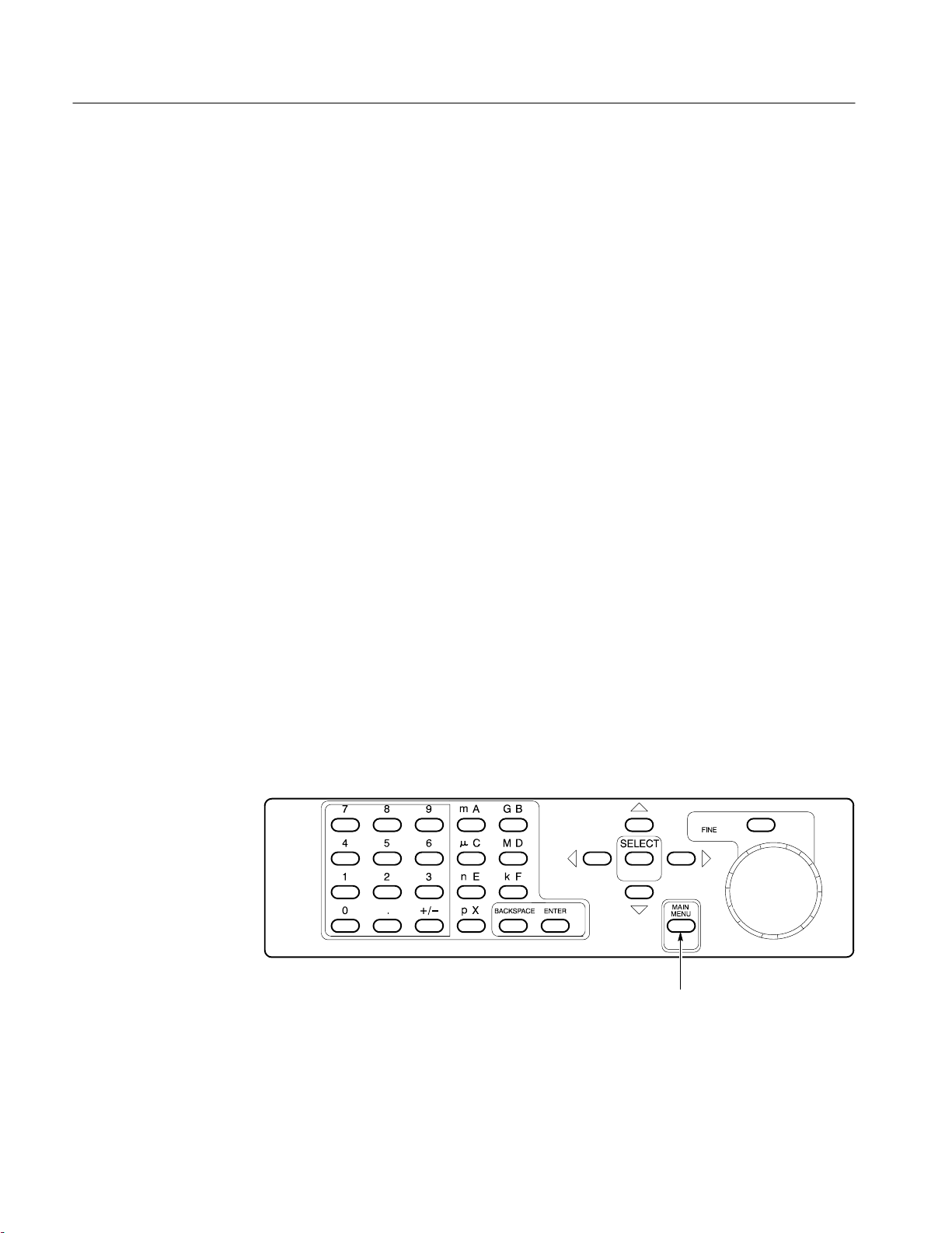
Screen Menus. The HFS 9000 implements controls as menus that are displayed
on the front-panel screen. Figure 1–1 shows the location of the MAIN MENU
button, which displays the top-level menu.
MAIN MENU Button
1–2
Figure 1–1: MAIN MENU Button Location
HFS 9000 User Manual
Getting Started
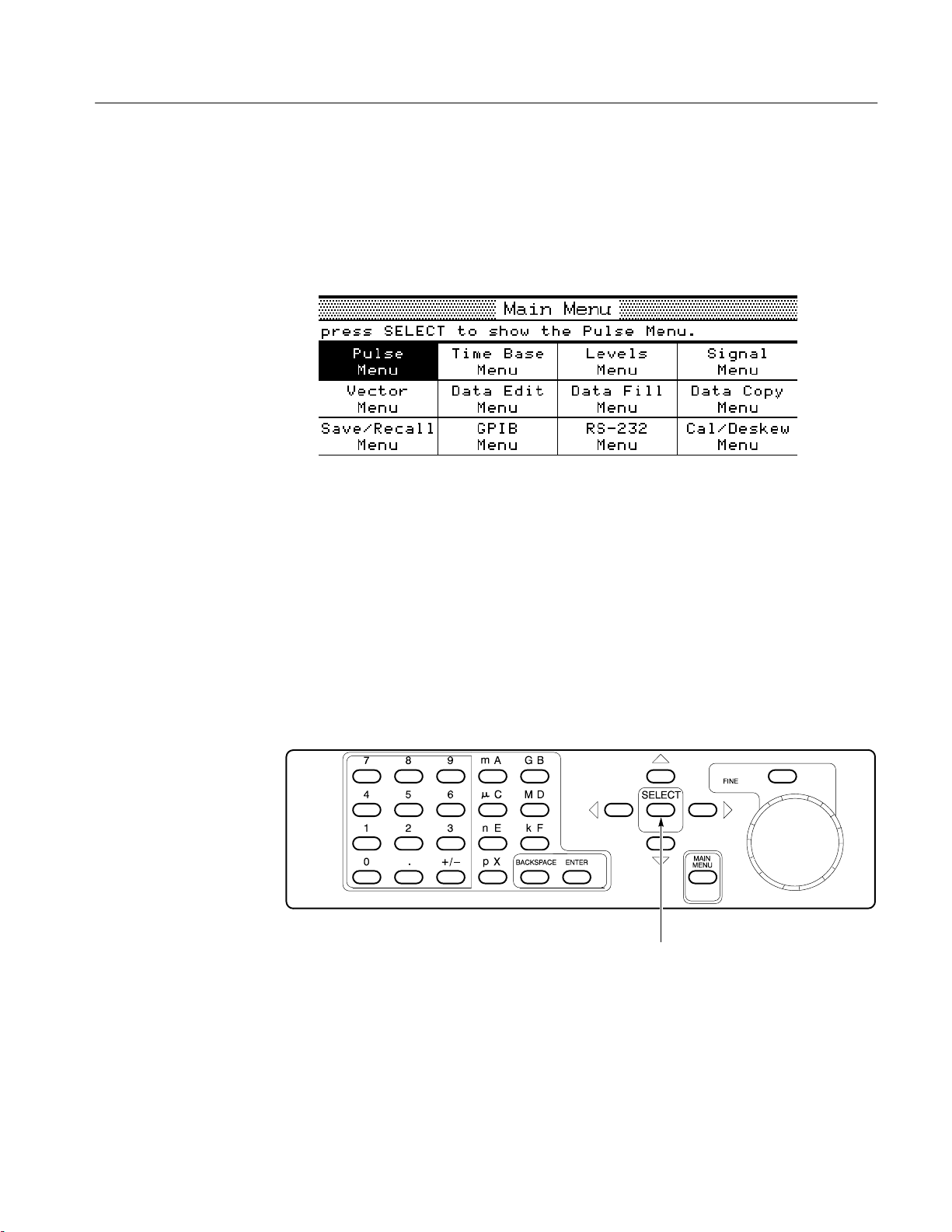
1. Press the MAIN MENU button.
Figure 1–2 shows the appearance of the Main menu. Each item in this menu
leads to a second-level menu. The menu you see may have a different menu
item highlighted, that is, black type on an amber background.
Figure 1–2: Main Menu Display
All menus have a name bar across the top and several rectangular menu
items beneath. Some menus have a prompt line between the name bar and
the menu items.
At all times, one and only one of the menu items is highlighted. The
SELECT button (Figure 1–3) will operate on this highlighted item. The
arrow keys surrounding the SELECT button let you change which item is
highlighted; each arrow button moves the highlighting to the next item in the
direction indicated.
SELECT and Arrow Buttons
HFS 9000 User Manual
Figure 1–3: The SELECT and Arrow Buttons
1–3

Getting Started
The Main menu gives you access to the twelve second-level menus:
H The Pulse menu controls the pulse generator parameters such as pulse
timing and voltage levels.
H The Time Base menu controls timing and triggering of the HFS 9000.
H The Levels menu sets voltage levels and limits for the pulse generators.
H The Signal menu controls channel display order, signal types, signal
names, and channel view.
H The Vector menu controls vector parameters.
H The Data Edit menu lets you edit the data streams produced by data time
generators.
H The Data Fill menu lets you fill data time generator channel memory.
H The Data Copy menu lets you copy blocks of data between data time
generator channels.
H The Save/Recall menu lets you save and recall Stimulus System settings.
This menu also has the reset control.
H The GPIB menu controls the GPIB parameters for remote programming.
H The RS-232 menu controls the serial port parameters for remote
programming.
H The Cal/Deskew menu provides calibration, self-test, instrument
identification, and pulse channel deskew functions.
The goal of this first part is to reset the HFS 9000. Since the reset control is
in the Save/Recall menu, you need to display this menu next.
2. Use the arrow buttons surrounding the SELECT button to move the menu
item highlight to the Save/Recall Menu item.
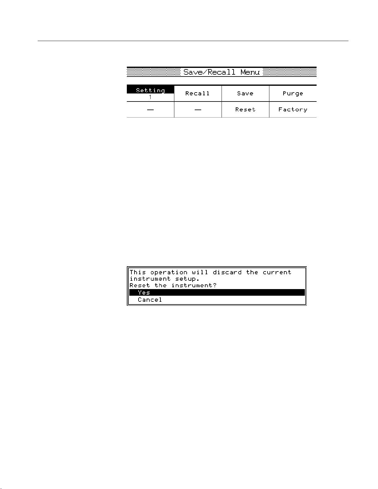
3. Press the SELECT button.
The Save/Recall menu, as shown in Figure 1–4, is displayed.
1–4
HFS 9000 User Manual
Getting Started
Figure 1–4: The Save/Recall Menu
Once in the Save/Recall menu, you can reset the HFS 9000 by selecting the
Reset menu item.
4. Use the arrow buttons to move the menu item highlight to the Reset menu
item.
5. Press the SELECT button.
Accidentally resetting the instrument can be inconvenient, especially if you
have spent some time getting the perfect setup. For your protection, the
HFS 9000 asks you to verify that you really want to reset.
To perform the verification, the HFS 9000 displays a temporary screen
dialog, as shown in Figure 1–5.
Figure 1–5: The Reset Verification Dialog
You can select from the options in the dialog by using either the up and
down Arrow keys, or by turning the knob. Once you have the proper
selection, press SELECT to perform the verified action.
6. Make certain that the Yes choice in the dialog is highlighted, and then press
the SELECT button to verify the reset request.
After the HFS 9000 resets, it displays the Main menu.
HFS 9000 User Manual
1–5
Getting Started
Part 2: Set the Time Base
The HFS 9000 provides several pulse or data time generation channels, but they
are all governed by a single time base. The next several steps set up the time
base to trigger itself repeatedly, and to have the time base specify a predetermined number of pulses from the pulse or data time generators.
The controls for the time base are found in the Time Base menu, shown in
Figure 1–6.
1. Use the arrow buttons to highlight the Time Base menu, then press the
SELECT button to display the Time Base menu.
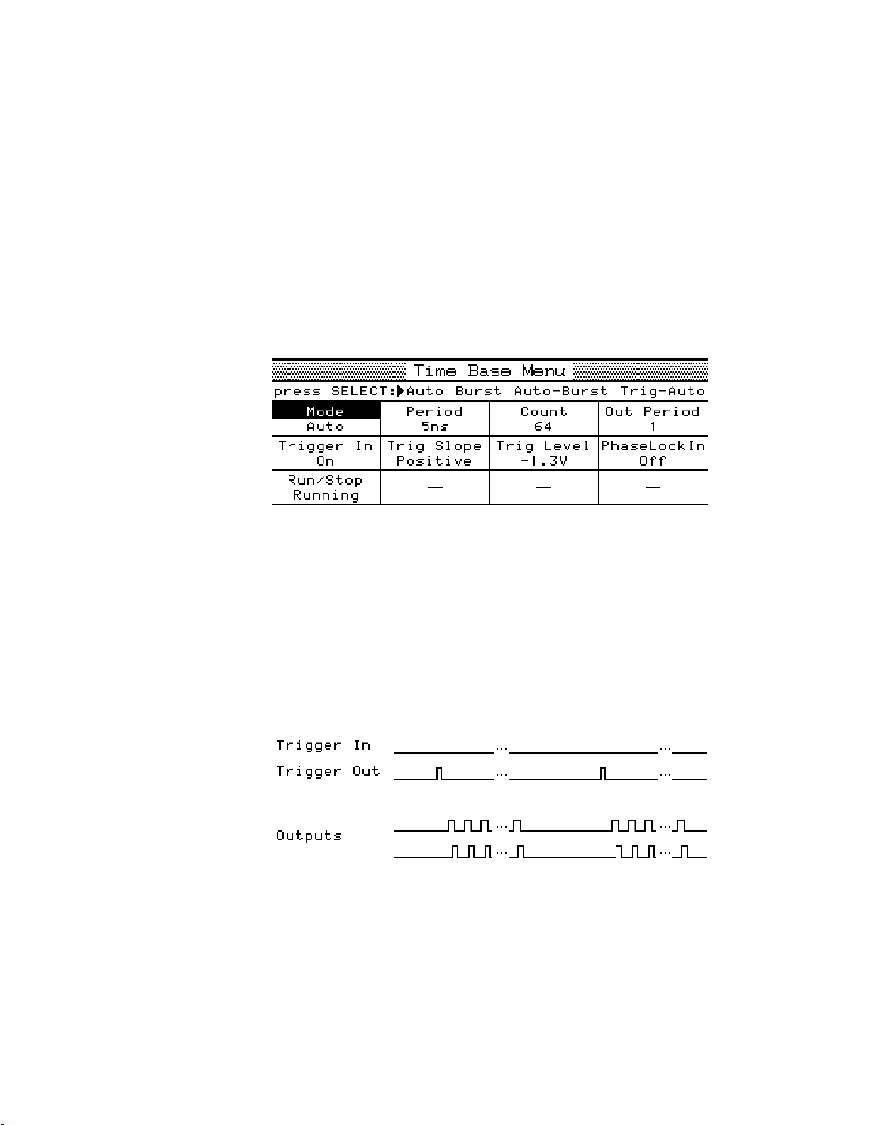
Figure 1–6: The Time Base Menu
The highlighted menu item is Mode, which you need to set for this example.
The time base normally waits for a trigger event, then specifies Count
number of pulses to be generated. After that, the time base pauses for a
re-arm time and then waits for the next trigger event. The display screen
above the Time Base menu graphically depicts this sequence. (see Figure 1–7).
Figure 1–7: Time Base Relationships
1–6
HFS 9000 User Manual

Getting Started
The Mode control has four possible settings:
H Burst mode produces a burst of pulses whenever a trigger event is
detected.
H Auto-Burst mode does not wait for a trigger before generating a burst of
pulses.
H Auto mode generates a continuous stream of pulses without waiting for
a trigger or delaying for re-arm time.
H Trig-Auto mode works like Auto mode except it does not begin until it
receives a trigger event.
To keep this example simple, we will use Auto Burst mode.
Set the mode control with the SELECT button. The prompt line, just below
the menu title, shows you the current mode setting with an arrow (
time you press SELECT, the arrow moves to a different setting and the text
in the Mode item changes.
). Each
2. Press the SELECT button twice. When you are done, the prompt line should
appear as in Figure 1–8.
Figure 1–8: Mode Set to Auto-Burst
Two other items in the top line of the Time Base menu, Period and Count,
control the generated pulses. When either of these items is highlighted, the
waveform display above the menu is augmented to more clearly illustrate the
parameter being adjusted with that item.
H Period controls the timing of the individual pulses produced by the pulse
generators. This can also be changed to be a Frequency control, as will be
demonstrated later in this tour.
H Count determines the number of pulses generated after the startup delay.
HFS 9000 User Manual
Both of these items can be adjusted with the knob or each can be entered using
the keypad. When using the knob, the FINE button above the knob can give you
more control through finer resolution.
3. Use the arrow keys to highlight the Period item.
1–7
Getting Started
4. Use the knob to adjust the period to 6.25 ns. This will require that you use
the fine control.
First, use the knob to set the Period to 6.2 ns. Then, press the FINE button
to make the knob increments smaller. Note that the FINE light turns on.
Finally, use the knob to set it to 6.25 ns.
Numeric values can also be entered through the keypad. Type in the number,
and, if needed, press a key to specify the unit prefix (p, n, , m, k, M, or G).
Indicate that you are finished by pressing the ENTER key. You never need
to enter the units, such as seconds or Volts. If you make a mistake, the
BACKSPACE key will back up character by character.
5. Use the arrow keys to highlight the Count item.
6. Enter the value 5 by pressing 5 and ENTER.
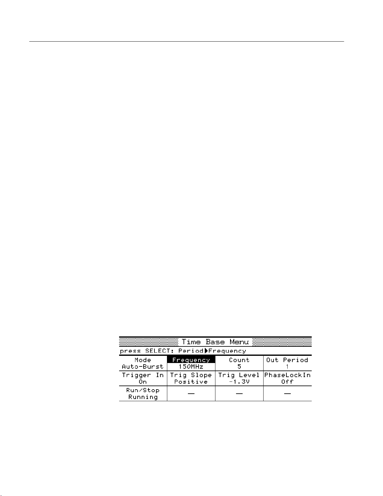
As mentioned above, the Period item can be changed to specify Frequency
instead. Period and frequency are two ways of specifying the same parameter.
When you use the SELECT button to change modes of this item, the readout
shows you the setting in that mode.
7. Use the arrow keys to highlight the Period item. Observe that the period
setting is 6.25 ns.
8. Press the SELECT button. Observe that the item changes to Frequency and
that the frequency setting is 160 MHz, the reciprocal of 6.25 ns.
9. Use the knob or the keypad to set the frequency to 150 MHz. If you left the
Fine knob control on from Step 4, turn it off to set the frequency quickly.
You have now set up the HFS 9000 to enable the output of pulses. You will see
the results in the next part, but first check to make sure your Time Base menu
appears as shown in Figure 1–9.
1–8
Figure 1–9: The Time Base Menu After Adjustment
HFS 9000 User Manual

Getting Started
The other settings do not require adjustment for this tutorial example. Since the
HFS 9000 is in Auto-Burst mode, no input trigger is needed to generate pulses.
The UNDO Button. Whenever you change a setting, the HFS 9000 remembers the
old setting as well. Should you then change your mind, you can press the UNDO
button. The UNDO button is located to the right of the display panel. Pressing
the UNDO button twice cancels the undo.
10. Press the UNDO button. Note that the original frequency setting of 160 MHz
is restored.
11. Press the UNDO button again. Note that your changed value, 150 MHz, is
returned.
HFS 9000 User Manual
1–9

Getting Started
Part 3: Turn On Pulse
Output
The pulse and data time generators are all synchronized by the time base, but
currently none of the pulse or data time generator channels are switched on. You
can turn on any channel from the Pulse menu, but it is easiest to turn on a
channel from the front panel.
Depending on the configuration of your HFS 9000, you have from one to nine
pulse generator cards, with up to four channels each. The controls for each card
appear as in Figure 1–10.
SMA Connector OUTPUT ButtonLight
HFS 9DG1 HFS 9DG2HFS 9PG2TIME BASE
1–10
Figure 1–10: Pulse Generator, Data T ime Generator, and Time Base Controls and
Connectors
HFS 9000 User Manual

Getting Started
1. Select any channel to use for output, and press the OUTPUT button for that
channel. Observe that the associated light turns on.
The HFS 9000 is now creating pulse trains. It puts out 5 pulses of 150 MHz
frequency. When that is done, it automatically starts over after the re-arm
time. If you have an oscilloscope, you can view the pulses that are being
generated.
2. Connect a cable from the associated OUTPUT connector to the signal input
connector of your oscilloscope.
3. Adjust your oscilloscope for a stable display of the pulses. If necessary, you
can also connect a cable from the Time Base card TRIGGER OUT
connector to the external trigger connector of your oscilloscope.
You may also observe the normal Burst mode operation of the HFS 9000.
4. Use the arrow keys on the HFS 9000 to highlight the Mode item of the Time
Base menu. Use the SELECT button to select Burst mode.
5. Observe that the oscilloscope is no longer triggered and displaying a signal.
Part 4: Setting Up a Data
Time Generator
6. Press the MANUAL TRIGGER button (to the right of the display panel).
Observe that each time you press this button, the oscilloscope shows one and
only one burst of output from the HFS 9000.
If a Data Time generator is installed in your HFS 9000, it can produce data
streams for device testing in addition to generating pulses. You can perform the
following steps only if your HFS 9000 has an HFS 9DG1 or HFS 9DG2 card
installed.
1. Perform all steps in “Reset the HFS 9000” of Getting Started, to reset all
HFS 9000 parameters to the factory defaults.
2. Use the arrow keys to highlight the Pulse menu, then press the SELECT
button to display the Pulse menu.
3. Using the Channel menu item, select a channel located on a data time
generator card.
For a channel to generate a data stream, the signal type of the channel must be
set appropriately. The available signal types are: NRZ-Non-Return to Zero; RZ,
Return-to-Zero; and R1, Return-to-One. A data time generator channel can also
be set to DC (direct current).
4. Highlight the Signal Type menu item in the Pulse menu. (Figure 1–11).
Turn the knob to change the signal type.
HFS 9000 User Manual
1–11

Getting Started
Figure 1–11: Setting the Signal Type
5. Observe how the illustration at the top of the display changes with the signal
type. Set the signal type to NRZ.
6. Press the MAIN MENU button.
7. Use the arrow keys to highlight the Data Fill menu and press the SELECT
button.
A channel is initially filled with zeros. You can change the data in the
channel using the Data Fill menu or by editing the data in the channel one bit
at a time in the Data Edit menu. The Data Fill menu is the quickest method
for placing data in a channel using the front panel.
The commands in the Data Fill menu work on a “Block” of vectors. A Block
is defined by a start vector and an end vector. Initially the block start and end
vectors are set to 0.
8. Highlight the Block End menu item. On the numeric keypad, press 1, 5, and
ENTER. This sets the block end vector to 15.
Blocks are filled using the Fill Block with Method menu item. The three
parameters for this menu item are Constant, Method, and Fill Scale. Constant
provides the value used to fill a block or the starting value for the Count Up,
Count Down and Random fill methods. Method specifies how a channel is
filled with data; the options are Constant, Invert, Count Up, Count Down, and
Random. Fill Scale is the number of vectors that are filled with a value before
generating a new fill value.
1–12
HFS 9000 User Manual

Getting Started
9. To set the fill method, use the arrow keys to highlight the Method menu
item.
10. Turn the knob to select each of the different fill methods. Observe the
descriptions that appear above the menu.
11. Select the Constant method.
12. Use the arrow keys to highlight the Fill Block with Method menu item.
Press the SELECT key.
13. A menu will appear informing you that the operation cannot be undone.
Press the SELECT key to allow the operation to proceed.
To view the results of the fill operation, you can view the channel data in the
Data Edit menu.
14. Press the MAIN MENU button. Highlight the Data Edit Menu item and
press SELECT.
When the Data Edit menu appears, you will see the selected channel and the
data that has filled it.
HFS 9000 User Manual
Figure 1–12: Viewing Channel Data
You can edit each of the bits in the channel from the front panel. Select a bit
by turning the knob and enter a new value from the numeric keypad.
1–13

Getting Started
15. Turn the knob to highlight vector 7.
16. Press 0 on the numeric keypad.
Observe that the 1 in vector address 7 is replaced by a 0 and the cursor
moves down to the next vector.
This completes your brief tour of the HFS 9000 Stimulus System. Refer to the
Operating Basics and Reference sections in this manual for more details on
operating your HFS 9000.
1–14
HFS 9000 User Manual


An Operator Overview
The Operating Basics section is arranged as an alphabetic list of topics. Each
topic covers one aspect of the operation of the HFS 9000. The topics that follow
this operator overview are:
Calibration Pulse Generators
Channels Reset
Data Time Generators RS-232-C
Deskew Saved Settings
GPIB Self Test
Levels Time Base
Phase Lock Trigger
Power On
Timing and Pulses (Burst and Auto-Burst Modes)
The Frequency or Period setting
determines the frequency or
duration of the pulse windows.
See page 2–62.
The Count setting determines the
number of pulse windows in a
burst — see page 2–62. Pulses
may occur at any time and be any
width within the pulse window.
Each channel may independently
set such pulse parameters as
width, phase, lead delay, and
trailing delay. See page 2–45.
The Out Period setting determines
which pulse window the output
trigger is associated with; in this
case it is the third pulse window.
See page 2–62.
Trigger Event
Trigger In
Channel
Outputs
Trigger Out
Startup Delay
(fixed at ~130 ns)
Time Zero
Reference
Pulse Windows
HFS 9000 User Manual
2–1

An Operator Overview
The HFS 9003 Front Panel
NEXT CHANNEL and PREVIOUS
CHANNEL buttons let you select a
channel in menus that have channel
parameters. This convenience avoids a
lot of menu navigation. See page 2–11.
The UNDO button restores the
HFS 9000 to the state it was in before
your last change. When you change
menus, you can no longer undo the
previous operation.
REMOTE light and SRQ button —
used for operator interaction when the
HFS 9000 is controlled from a
computer or controller. See page 2–31.
The Generator cards have connectors for normal
OUTPUT and inverted OUTPUT, along with
buttons to turn the outputs on and off and lights to
indicate whether those outputs are on. The
TRANSDUCER IN connector (PG cards only)
lets you apply a logic signal to directly drive a
channel. See pages 2–13 and 2–45.
RUN/STOP lets you start and stop the
time base as necessary. The RUNNING
light indicates whether or not the time
base is running.
The Time Base card has
connectors for timing input and
output, including the TRIGGER
IN, TRIGGER OUT connectors
(see page 2–65), the PHASE
LOCK IN and FRAME SYNC IN
connectors (see page 2–41), and
the SKEW CAL IN connector (see
page 2–7).
The MANUAL TRIGGER button
simulates a trigger event that normally
occurs as a signal at the TRIGGER IN
connector. See page 2–68.
2–2
Numeric keypad lets you type a
number for any selected menu
item having a numeric value. End
your number by pressing the
ENTER button. See page 1–8.
SELECT, arrow, and MAIN MENU buttons
navigate through the menus. MAIN MENU
displays the main menu. The arrow buttons
change which menu item is selected — see
page 2–4. In the main menu, SELECT
displays the selected menu. In other menus,
SELECT may perform an action or change
the way an item works — see page 1–7.
The knob and FINE button let you adjust the
value of any selected menu item that has a
numeric value. The FINE button gives you finer
knob control. The FINE light tells you when the
knob is in fine granularity mode. See page 1–7.
The CPU card has connectors for
the SERIAL PORT (see page
2–53) and for the GPIB bus (see
page 2–29).
ON/STANDBY switch turns on the HFS9000
or turns it off (standby). Even when on
standby, some circuits have line power
applied. To remove all power, disconnect the
power cord from the HFS 9000.
HFS 9000 User Manual

The HFS 9009 Front Panel
SELECT, arrow, and MAIN MENU buttons
navigate through the menus. MAIN MENU
displays the main menu. The arrow buttons
change which menu item is selected — see
page 2–4. In the main menu, SELECT
displays the selected menu. In other menus,
SELECT may perform an action or change the
way an item works — see page 1–7.
ON/STANDBY switch turns on the
HFS 9000 or turns it off (standby).
Even when on standby, some circuits
have line power applied. To remove all
power, disconnect the power cord from
the HFS 9000.
The REMOTE light and SRQ button
are used for operator interaction when
the HFS 9000 is controlled from a
computer or controller. See page 2–31.
The knob and FINE button
let you adjust the value of
any selected menu item
that has a numeric value.
The FINE button gives you
finer knob control. The
FINE light tells you when
the knob is in fine
granularity mode. See
page 1–7.
An Operator Overview
The UNDO button restores the
HFS 9000 to the state it was in before
your last change. When you change
menus, you can no longer undo the
previous operation.
The MANUAL TRIGGER button
simulates a trigger event that
normally occurs as a signal at the
TRIGGER IN connector. See
page 2–68.
RUN/STOP lets you start and stop
the time base as necessary. The
RUNNING light indicates whether
the time base is running or not.
Numeric keypad lets you
type a number for any
selected menu item having
a numeric value. End your
number by pressing the
ENTER button. See
page 1–8.
The CPU card has connectors for the
SERIAL PORT (see page 2–53) and for
the GPIB bus (see page 2–29).
HFS 9000 User Manual
The Time Base card has connectors for
timing input and output, including the
TRIGGER IN and TRIGGER OUT
connectors (see page 2–65), the PHASE
LOCK IN and FRAME SYNC IN connectors
(see page 2–41), and the SKEW CAL IN
connector (see page 2–7).
NEXT CHANNEL and PREVIOUS
CHANNEL buttons let you select a
channel in menus that have channel
parameters. This convenience avoids a
lot of menu navigation. See page 2–11.
The Pulse Generator cards have connectors
for normal OUTPUT and inverted OUTPUT,
along with buttons to turn the outputs on and
off and lights to indicate whether those outputs
are on. The TRANSDUCER IN connector lets
you apply a logic signal to directly drive a
channel. See pages 2–13 and 2–45.
2–3

An Operator Overview
Menu Navigation
1. Press the MAIN MENU button to display the top-level menu.
2. Use the arrow buttons to move to the menu you want to display.
2–4
3. Press the SELECT button to display that menu.
HFS 9000 User Manual

Menu Map
An Operator Overview
HFS 9000 User Manual
2–5

An Operator Overview
Menu Map (Cont.)
2–6
HFS 9000 User Manual

Calibration
The HFS 9000 is shipped in a calibrated state, with the outputs deskewed to the
front panel. Calibration settings are saved in a special non-volatile memory
which is separate from any other memory in the instrument. Calibration adjusts
the instrument to its internal voltage and timing references.
Calibrating the HFS 9000
It is important to calibrate the HFS 9000 after the instrument has been repaired
or after the instrument has been reconfigured by adding or changing cards. It is
also necessary to calibrate the HFS 9000 if you operate the instrument in an
environment where the ambient temperature differs by more than 5_ C from the
temperature of the last calibration. As a matter of routine, you should calibrate
the HFS 9000 every six months.
To calibrate the HFS 9000, use the Calibrate item in the Cal/Deskew menu.
Figure 2–1 shows this menu.
HFS 9000 User Manual
Figure 2–1: The Cal/Deskew Menu
Run the calibration procedure only when the HFS 9000 has been powered on for
20 minutes in the temperature environment you expect it to be used. You will
need a 20 inch SMA cable; the cable supplied as a standard accessory is
acceptable. The calibration process will take approximately one minute for every
channel installed in the HFS 9000.
When you select the Calibrate item in the Cal/Deskew menu, a dialog box asks
you for verification. If you proceed, the HFS 9000 will prompt you to attach the
SMA cable from the front panel SKEW CAL IN connector first to the TRIG-
GER OUT connector, and then to each channel OUTPUT connector in turn.
During the time that the channels are connected, calibration is performed
automatically.
2–7

Calibration
Diagnostic Failure of Calibration Memory
Whenever you power on the HFS 9000, diagnostics check the integrity of the
calibration memory. If the test fails, the instrument may require service. When
this happens, nominal values are put into calibration memory, and the instrument
will be uncalibrated. However, the HFS 9000 will let you continue to operate the
instrument after the initial warning that calibration memory has been reset.
Check out the instrument to be certain it is running correctly and run the
calibration procedure before operating the instrument.
If the instrument configuration has been changed since last power on (for
example, boards have been changed or firmware memory has been updated), the
power-on diagnostics will detect this as a failure of calibration memory integrity.
Run the calibration procedure before operating the instrument.
NOTE. Some features will not function if the HFS 9000 is in an uncalibrated
state.
2–8
HFS 9000 User Manual

Channels
Channel Names
You have from 2 to 36 channels of output, depending on the type and number of
cards you have installed in your HFS 9000 system. The HFS 9PG1 and
HFS 9PG2 pulse generator cards provide two output channels, while the
HFS 9DG1 and HFS 9DG2 data time generator cards provide four output
channels.
Each pulse generator card is assigned the letter designation A, B, C, D, E, F, G,
H, or I depending on its physical position in the Stimulus System mainframe.
The channels on HFS 9PG1 and HFS 9PG2 cards are numbered 1 and 2. The
channels on HFS 9DG1 and HFS 9DG2 cards are numbered 1, 2, 3, and 4. The
full designation for a channel is a letter and a number; for example A1, C2, H4,
etc. Figure 2–2 shows the locations of the channels in a typical instrument.
Figure 2–2: Channel Locations
Channel B1
Channel B2
Channel C2
Channel C1
Channel A1
Channel C4
Channel C3
Channel A2
Channel B4
Channel B3
HFS 9000 User Manual
2–9

Channels
Channel Controls
On HFS 9PG1, HFS 9PG2, and HFS 9DG1 cards, each channel has both normal
OUTPUT and inverted OUTPUT
connector per channel, OUTPUT. Each output connector of each channel has a
button to turn on or off that output, and a light telling whether or not that output
is on. In addition, each channel on HFS 9PG1 and HFS 9PG2 cards have a
TRANSDUCER IN connector. (For more information on the Transducer mode,
see page 2–49.) Figures 2–3, 2–4, and 2–5 show the layout of controls for the
different pulse and data time generator cards.
connectors. The HFS 9DG2 card has only one
HFS 9PG2
Figure 2–3: Channel Controls on an HFS 9PG2 Card
Figure 2–4: Channel Controls on an HFS 9DG1 Card
Figure 2–5: Channel Controls on an HFS 9DG2 Card
HFS 9DG1
HFS 9DG2
2–10
You can also turn off normal and inverted output for any channel with the Pulse
menu items Output and ~Output. When an output is off, the channel is
internally tri-state. Off does not drive an output to ground.
HFS 9000 User Manual

Selecting Channels
Channels
Several menus provide controls that apply to individual channels. In these
menus, the upper left menu item lets you set which channel the other menu items
control. You use the SELECT button or the knob to select the desired channel.
Once you have set the desired channel, you can use the other menu items to
control the parameters for that channel.
An alternate method of selecting channels is to use the NEXT CHANNEL and
PREVIOUS CHANNEL buttons at the left of the display.
The Pulse menu, the Levels menu, and the Signal menu have associated channel
displays above the menu. In these displays, each channel is labeled with its
channel name (A1, C2, etc.). The name of the channel that is selected to be
controlled by the other menu items is highlighted, that is, displayed in black
lettering on an amber background. Figures 2–6, 2–7, and 2–8 show these three
menus and indicate the highlighting on the associated displays.
Selected
Channel
Figure 2–6: Pulse Menu, Showing Channel Selection
HFS 9000 User Manual
2–11

Channels
Selected
Channel
Figure 2–7: Levels Menu, Showing Channel Selection
Selected
Channel
Figure 2–8: Signal Menu, Showing Channel Selection
2–12
HFS 9000 User Manual

Data Time Generators
The HFS 9DG1 and HFS 9DG2 Data Time Generators combine the capabilities
of a data time generator, pulse generator, and switch matrix in a single instrument. As part of the HFS 9000 Stimulus System, the data time generator can
deliver complete data and timing signals to the circuit under test. Within the data
time generator, every output is capable of producing any type of data and
formatting — not just data and pulses. Complete control over rise and fall times,
widths, and voltage levels on all data is provided. Because of their unique digital
architecture, the data time generators can place an edge anywhere, even delaying
waveforms across cycle boundaries.
Controls for the data time generators are accessed in several menus. Controls that
affect the pulse parameters of the data time generators are in the Pulse menu, as
shown in Figure 2–9. For more information on pulse parameter controls, see
page 2–45.
HFS 9000 User Manual
Figure 2–9: The Pulse Menu
Menus that control data generation parameters are the Signal menu, the Data Fill
menu, the Data Copy menu, and the Data Edit menu.
2–13

Data Time Generators
Turning Channels On and Off
The HFS 9DG1 provides two output connectors for each channel. Channels are
identified by number; they are labeled CH 1 through CH 4. Each channel
provides both normal and logically inverted output and are labeled OUTPUT
and OUTPUT
labeled CH 1 through CH 4.
Each output connector has a button to turn that output on or off, and a light
showing whether or not that output is on. You can also turn on or off the normal
or inverted output of any channel using the Pulse menu items Output and
~Output.
Naming a Channel
Generally, a channel is referred to by its slot and channel number; for example,
you would refer to channel 1 of the card in slot A as channel A1. Additionally,
you can identify a channel with a name. This would enable you to identify the
signal going to the Write Enable pin of the DUT (device under test) as “WE”
rather than A1. Any channel on any card can be given a name; this feature is not
limited to the data time generator cards.
. The HFS 9DG2 provides one output connector for each channel,
Assigning a name to a channel is performed by the Signal Name item in the
Signal menu (see Figure 2–10).
Figure 2–10: The Signal Menu
To assign a name to a channel, select the channel using the Channel menu item.
Select the Signal Name menu item and press SELECT. The dialog box appears
as in Figure 2–11.
2–14
HFS 9000 User Manual

Figure 2–11: The Signal Name Dialog Box
Data Time Generators
To enter a name, choose a character by turning the knob or pressing the arrow
keys. When the character is highlighted, press SELECT to signify your selection
and enable selection of the next character. A signal name can be up to six
characters long. When you are finished selecting characters, press ENTER. The
dialog box will disappear and the new signal name will appear in the Signal
Name and Channel menu items (see Figure 2–12).
Figure 2–12: Signal Menu After Entering Signal Name
HFS 9000 User Manual
2–15

Data Time Generators
You can also name buses. To do this, assign the same name to two or more
channels, but use different numbers as the last character in the name. You could
create an bus named “ADDRx”, where x represents the number of each line of
the bus (see Figure 2–13).
Figure 2–13: Naming a Bus
Signal Type
If you create a bus, you can choose to view the bus by individual channel or as a
single entity that represents the whole group. You change the view of channels
with the View item. You can choose to view channels as a Channel or as a
Group. In this manual, we will use “Signal” to refer to a channel that has been
named. Figure 2–14 below is the same display as above except that the View is
set to Group.
Figure 2–14: Viewing a Bus by Group
A Signal on an HFS 9DG1 or HFS 9DG2 can be of five different types: Pulse,
NRZ (Non-Return to Zero), RZ (Return to Zero), R1 (Return to One), and DC.
The signal type is assigned with the Signal Type menu item (see Figure 2–15).
2–16
HFS 9000 User Manual

Data Time Generators
Figure 2–15: Assigning Signal Type
To set the signal type, select the channel using the Channel menu item. Select the
Signal Type menu item. Turn the knob to select the correct signal type (the
Transducer signal type appears in the menu but it cannot be assigned to data
time generator channels).
Changing Display Order
You can change the order in which signals are displayed using the Move
Up/Down and Reset Order menu items in the Signal menu. To change the
display order of signals, select the channel you want to move with the Channel
menu item. After selecting the channel you want to move, select the Move Up/
Down menu item (see Figure 2–16). To move the channel to a different position
in the display order, turn the knob.
Figure 2–16: Changing the Display Order
HFS 9000 User Manual
If you wish to return the display order to the default order (A1, A2, A3, A4, B1,
B2, etc.), select the Reset Order menu item and press SELECT. A dialog box
2–17

Data Time Generators
Entering Vector Data
will appear asking you to confirm that you wish to reset the channel order. The
default answer is Yes. To select Cancel, use either the knob or the up/down
arrow keys to change the selection. When the correct response is highlighted,
press SELECT.
Data can be entered in three ways. One way is to enter data one bit at a time
using the Data Edit menu. Another way is to use the Data Fill and Data Copy
menus. The third method is used if you have generated test vectors with a CAD
system or Tektronix BitWriter Software. With this method, you transfer your
vector data into the HFS 9000 via the programming interface. For more
information on entering data via the programming interface, please refer to
page 3–121.
Editing Vectors
Start Vector Indicator
Vectors
Loop Vector Indicator
You view and edit the contents of vectors from the Data Edit menu. There are no
menu items in the Data Edit menu. To display the Data Edit menu, select Data
Edit Menu from the main menu (see Figure 2–17).
Signals
Cursor
This line indicates the direction the cursor
will move when the knob is turned.
These represent the data stream for
each Signal. Each number can
represent one, two, or four bits of data
depending on the Data Radix.
2–18
End Vector Indicator
Figure 2–17: The Data Edit Menu
HFS 9000 User Manual

Data Time Generators
To edit the contents of a vector, move the cursor using the knob or the arrow
keys. When the appropriate datum is highlighted, type the change using the
keypad. When you type the change, the highlighted datum is changed and the
cursor moves to the next datum. Note that the number of bits each datum
represents depends on the Data Radix setting.
Vector Parameters
There are several parameters related to vectors; these parameters are accessed
from the Vector menu. From the Vector menu, you can set the Start, Loop, and
End addresses. The vector radix, data radix, and time base mode are also set in
this menu (see Figure 2–18).
HFS 9000 User Manual
Figure 2–18: The Vector Menu
To set vector parameters, select the channel whose parameters you wish to set
using the Channel menu item. Next, select the parameter you wish to set and use
the knob (or numeric keypad as appropriate) to change the value.
H Start sets the vector of the first data bit output.
H Loop sets the start vector of all cycles except the first. The Loop value is
used only in Auto and Trig Auto modes; it is ignored in Burst and Auto
Burst modes. Loop is useful if you need to send setup information with the
first cycle of data, but don’t want it to be sent out on subsequent cycles. Of
course, Loop can be set to the same vector as Start.
There are some constraints on Loop size (defined as: End – Loop + 1). If
vector consumption (defined as: End – Start +1) is:
2–19

Data Time Generators
≤8192, there are no constraints on Loop size
> 8192, then Loop size must be divisible by 2
>16384, then Loop size must be divisible by 4
>32768, then Loop size must be divisible by 8
H End sets the vector of the last data bit output.
NOTE. Start, Loop, End, Mode, and Vec Radix are global values. If you change
these settings for any channel, the change applies to all channels.
H The Mode menu item determines how data is output from the data time
generator. It is the same as the Mode menu item in the Time Base Menu.
In Burst mode, the HFS 9000 waits for a trigger event at the TRIGGER IN
connector, a remote *TRG command, or a press of the MANUAL TRIG-
GER button. When a trigger event is detected, the HFS 9000 waits for
approximately 130 ns (the startup delay) before outputting data. Data output
begins with the Start vector and stops with the End vector. The HFS 9000
then awaits the next trigger event.
In Auto-Burst mode, output is similar to Burst, except that the HFS 9000
creates it own trigger events. There is a delay of approximately 15 s
between bursts.
H In Auto mode, data is output continuously without waiting for trigger events
and without any startup events. Data output begins with the Start vector.
Once End is reached, the output begins again at Start (or Loop if it is
different from Start) and continues until stopped by a knob turn or ASCII
interface command (RS-232-C or GPIB).
In Trig-Auto, the output is the same as with Auto mode, but output does not
begin until a trigger event is received. The HFS 9000 waits for a trigger
event at the TRIGGER IN connector, a remote *TRG command, or a press
of the MANUAL TRIGGER button.
If data output is stopped when Mode is set to Auto or Trig Auto, note that all
channels may not stop on the same vector. Additionally, if a signal is set to
NRZ and filled with “1”s as data, the channel may stop in a “0” state.
H Vec Radix specifies how vectors are displayed.
H Data Radix specifies how data is displayed in the Vector Edit menu. Data
Radix applies only to the selected channel.
Filling Vectors with Data
2–20
To quickly fill vectors with data, use the Data Fill menu (see Figure 2–19). The
underlying concept used in the Data Fill menu is the idea of a Block. A Block is
HFS 9000 User Manual

Data Time Generators
a group of vectors. You specify a Block using a starting vector and either an
ending vector or a block size. Once a Block is appropriately specified, you either
fill the block with data or clear the block of data.
A Block is filled using the Fill Block with Method menu item. The three
parameters for Fill Block with Method are Constant, Method, and Fill Scale.
Figure 2–19: The Data Fill Menu
H Channel selects the Signal (named channel) or bus on which the Fill Block
with Method and Clear Block commands operate.
H Block Start sets the vector where fill or clear operations begin. Turn the
knob or use the numeric keypad to change the Block Start vector.
H Block End sets the last vector in the Block. Turn the knob or use the
numeric keypad to change the Block End vector. Pressing SELECT while
Block End is highlighted changes the menu item to Block Size.
Block Size provides a second method of defining a block. Block Size sets
the size of the block, regardless of the Block Start vector.
H Clear Block sets all the bits in the Block to zero. Note that if View is set to
channel, only the selected channel is cleared. If View is set to Group, all
channels in the specified bus are cleared.
H Constant is a number used by the Method menu item. Depending on the fill
method selected, the constant is the number used to fill a Block or a
HFS 9000 User Manual
2–21

Data Time Generators
parameter used when filling a block. Note that valid numbers for Constant
depend on the Data Radix setting. To change the constant, turn the knob or
use the numeric keypad.
H Method specifies the algorithm used to fill a Block with data.
Constant fills the Block with the value in the Constant menu item.
Invert logically inverts the value of all the data in the Block.
Count Up fills each vector in the Block with an incrementally larger value.
Count Up starts with the value specified by the Constant menu item.
Count Down fills each vector in the Block with an incrementally smaller
value. Count Down starts with the value specified by the Constant menu
item.
Random fills vectors in the Block with a pseudo-random data pattern. The
pattern generated is based on the value of Constant.
H Fill Scale is a multiplier. It sets the number of vectors that receive each fill
pattern. For example, if the fill method is set to Count Up and Constant is set
to 0, then the Start vector is filled with a 0, the next vector receives a 1, the
next vector receives a 2, etc. If Fill Scale is set to 3, then the Start vector and
the next two vectors receive 0s, the next three vectors receive 1s, etc.
Figures 2–20 and 2–21 show the result of setting Fill Scale to 1 and to 3.
2–22
Fill Scale was set to 1 when this block was filled.
Thus, every vector receives a different value.
Figure 2–20: A Block Filled with Fill Scale Set to 1
HFS 9000 User Manual

Data Time Generators
Fill Scale was set to 3 when this block was filled.
Thus, each group of 3 vectors receives the same value.
Copying Vector Data
Figure 2–21: A Block Filled with Fill Scale Set to 3
H Selecting Fill Block with Method fills the Block using the parameters set in
Constant, Method, and Fill Scale.
You can also copy data in one Block to another using the Data Copy Menu (see
Figure 2–22). The Data Copy menu provides the capability to copy a block of
data from one channel to another or to duplicate a block of data within the same
channel. You can also swap blocks of data between channels or within the same
channel.
Aside from copying blocks of data, the Data Copy Menu can be used to insert a
new vector into a Block. To insert a new vector into a Block, just copy the Block
to a Dest Start vector one higher than the new vector. For example, if you need to
insert a new vector at 000010, copy the vectors from 000010 through the end of
the Block to a Dest Start address of 000011 (1 higher than 000010). Then edit
the new vector in the Data Edit menu. You can delete single vectors using the
same method — set the Dest Start vector to one less than the vector to be
removed.
HFS 9000 User Manual
2–23

Data Time Generators
Figure 2–22: The Data Copy Menu
H Channel selects the Signal (named channel) or bus on which the Copy
Block to Dest and Swap Block with Dest commands operate.
H Block Start sets the vector where copy or swap operations begin. Turn the
knob or use the numeric keypad to change the Block Start vector.
H Block End sets the last vector in the Block. Turn the knob or use the
numeric keypad to change the Block End vector. Pressing SELECT while
Block End is highlighted changes the menu item to Block Size.
Block Size provides a second method of defining a block. Block Size sets
the size of the block, regardless of the Block Start vector.
H Copies sets the number of times the Block is copied.
H Dest Chan specifies the channel that will receive the copied Block.
H Dest Start sets the vector where the copied Block will begin.
H Swap Block with Dest swaps the Block defined by Block Start and Block
End/Size with the Block that begins at Dest Start.
H Copy Block to Dest copies the Block defined by Block Start and Block
End/Size to the Block that begins at Dest Start.
2–24
H Vec Radix specifies how vectors are displayed in the Vector Edit menu.
H View sets the display mode to either Channel or Group.
HFS 9000 User Manual

Deskew
You can adjust two parameters to deskew the HFS 9000 so that its timing
matches the external circuitry you are working with. Both these parameters,
Pretrigger and Chan Delay, are in the Cal/Deskew menu as shown in Figure 2–23.
NOTE. Channel delay is set for each channel individually, while Pretrigger
affects all channels by changing the delay relative to the HFS 9000 output
trigger.
Channel Delay
Figure 2–23: The Cal/Deskew Menu
You can set Chan Delay (channel delay) independently for each channel
(Figure 2–24 shows the result of deskewing one channel). Channel delay adjusts
the time between the trigger out the detection of a trigger event at the TRIG-
GER IN connector and the beginning of the first pulse window of the burst.
There is normally a delay of approximately 130 ns between these two events.
Channel delay lets you adjust the delay for each channel from –60 ns to 2 s.
This value is added to the 100 ns internal delay.
In the Cal/Deskew menu, the Channel menu item lets you set which channel the
Chan Delay menu item controls. Use the SELECT button or the knob to select
the channel. Once you have set the desired channel, you can set the channel
delay for that channel. An alternate method of channel selection is to use the
NEXT CHANNEL and PREVIOUS CHANNEL buttons next to the display.
HFS 9000 User Manual
2–25

Deskew
Before Deskew
Long Cable
Short Cable
After Deskew
Long Cable
Short Cable
Chan Delay added to
channel with short cable, to
synchronize pulse outputs.
Figure 2–24: Deskewing Channels
Follow this sequence to deskew several channels so that they deliver pulses
simultaneously to your device under test:
1. Connect the generator channels to the device under test using the exact
cabling that you will use in the actual testing.
2. Set the Chan Delay of each channel to zero.
3. Turn on pulse output for each channel you are using. On each channel, set
the Lead Delay to zero or the Phase to 0%. Set the Count to 1.
4. Using an oscilloscope, measure the time between the trigger event on the
trigger signal and the rising edge of the pulse of each channel. Note which
channel has the longest time delay; this is the reference channel.
5. For each channel in turn, adjust the Chan Delay until the time between the
trigger event and the rising edge of the channel pulse matches that of the
reference channel.
You can do this arithmetically, by computing the time difference and setting
Chan Delay to that value. Alternately, you can do this using the oscilloscope, by probing each channel with the same oscilloscope probe and
adjusting the Chan Delay until the pulse timing matches the reference
channel.
2–26
HFS 9000 User Manual

Trigger Out Pretrigger
Deskew
This procedure synchronizes the channels so that they all deliver pulses to the
device under test simultaneously. The procedure compensates for timing
differences in the electrical paths of the channels, for example those caused by
unequal cable lengths.
Once you have deskewed the channels, you can introduce controlled timing
variations by using the Lead Delay or Phase menu items.
The output trigger can be adjusted to occur before the beginning of the specified
pulse window. The default setting of 70 ns means that the trigger out signal
appears 70 ns before the beginning of the pulse window.
Pretrigger can be used to compensate for the delay times incurred by cabling
between the TRIGGER OUT connector and the device to be triggered.
Pretrigger is also useful to compensate for an oscilloscope insertion delay; for
example, the typical insertion delay for the Tektronix CSA 803 is approximately
35 ns.
HFS 9000 User Manual
2–27

Deskew
2–28
HFS 9000 User Manual

GPIB
You can use the GPIB (IEEE 488.2-1987) interface to control the HFS 9000
from a remote controller or computer. The Reference section of this manual,
gives you step-by-step details of how to set up the HFS 9000 for remote
operation. The following information describes the settings and controls that
affect GPIB operation.
Connect your HFS 9000 to the GPIB using an IEEE STD 488 GPIB cable
(available as Tektronix part number 012-0991-00). Figure 2–25 shows the
location of the GPIB connector on the front of the HFS 9000.
HFS 9000 User Manual
2–29

GPIB
GPIB Connector
GPIB Connector
Figure 2–25: GPIB Connector Location
2–30
HFS 9000 User Manual

Operator Controls
GPIB
One common application for the HFS 9000 is as one instrument in a suite of
automated test equipment. In this environment, the controlling program may
need to operate the HFS 9000 for extended periods without operator intervention. The program may need to stop to have the operator perform some specific
action. The program then needs to have some indication from the operator that
the operator action has been completed and the program can continue the suite of
tests.
The HFS 9000 supports this environment in two ways:
H The front-panel interface of the HFS 9000 can be locked out (disabled) and
unlocked using commands sent from a remote controller or computer. When
the front panel is locked out, the REMOTE light at the left of the display is
lit. However, the SRQ button and the channel buttons on the pulse generator
cards cannot be locked out. These buttons are always operational regardless
of the state of lockout.
H The operator can send a trigger to the controlling program by pressing the
SRQ button, just below the REMOTE light (see Figure 2–26).
HFS 9000 User Manual
2–31

GPIB
REMOTE Light
SRQ Button
SRQ Button
REMOTE
Light
Figure 2–26: SRQ Button and REMOTE Light Locations
When the program expects the operator to perform some action before it can
continue, it unlocks the front panel interface and displays a message to prompt
the operator. The operator then performs the necessary action, after which he or
she presses the SRQ button. The program recognizes the button press, locks out
the front panel, and continues to the next automated test.
2–32
HFS 9000 User Manual

The GPIB Menu
GPIB
Figure 2–27: The GPIB Menu
NOTE. The settings of the GPIB parameters are not changed when you reset or
factory reset the HFS 9000 or when you recall settings.
H Address lets you set the device address of the HFS 9000 (see Fig-
ure 2–27).Valid device addresses are 0 through 30. Once the device address
is set, all other devices will communicate with the HFS 9000 using its device
address. Every device on a GPIB bus must have a unique device address.
H On Bus lets you “turn off” or “turn on” the GPIB interface. When set to Off,
the HFS 9000 GPIB interface is disabled and the remaining devices on the
bus operate as if the HFS 9000 were not connected to the bus.
H Debug specifies whether commands and control settings appear in the
HFS 9000 display. When debug is on, a display window appears showing the
most recent commands sent to the HFS 9000, and the status of several
control settings. Appendix C, Interface Specifications, gives complete
information about using debug mode.
HFS 9000 User Manual
2–33

GPIB
2–34
HFS 9000 User Manual

Levels
You can set the voltage levels that the HFS 9000 uses for logical high and logical
low. You can also limit the voltage levels that can be set with the normal level
controls. Voltage level and level limit controls are provided for each channel
individually. The output voltage range varies between cards as shown in
TableĂ2–1.
T able 2–1: Output Voltage Limits
Pulse/Data Time Generator Minimum Low Level Maximum High Level
HFS 9PG1 –2 V +2.6 V
HFS 9PG2 –2 V +5.5 V
HFS 9DG1 –2.5 V +5.0 V
HFS 9DG2 –2.0 V +5.5 V
When you turn level limit on, the voltage level settings for each channel are
adjusted, if necessary, to be within the limit boundaries set for that channel.
Setting Voltage Levels
NOTE. Turning limiting off does not restore the channel voltage levels to their
previous, unlimited values.
The controls for levels are located in the Pulse Menu (see Figure 2–28) or the
Levels Menu (see Figure 2–29).
HFS 9000 User Manual
2–35

Levels
Figure 2–28: The Pulse Menu
The Pulse menu has these level controls:
H Channel lets you set the channel that the other menu items control. Use the
SELECT button, the knob, or the PREVIOUS CHANNEL and NEXT
CHANNEL buttons to select channels.
Setting Level Limits
H High Level and Low Level are the voltage levels used for logical high and
low. These can be set by knob or entered by keypad. If limiting is on, you
will not be able to extend the voltages beyond the limits.
You can use the SELECT button to change High Level and Low Level into
Amplitude and Offset. Amplitude is the voltage difference between the
levels. Offset is the voltage level assigned to the midpoint between the
levels.
The controls for level limits are located in the Levels Menu (see Figure 2–29).
Controls for voltage levels are also provided here. The associated display
graphically shows the levels and limits for each channel.
2–36
HFS 9000 User Manual

Levels
Voltage Bar
Limit
Brackets
Figure 2–29: The Levels Menu and Associated Display
The Levels menu has these controls:
H Channel lets you set the channel that the other menu items control. Use the
SELECT button, the knob, or the PREVIOUS CHANNEL and NEXT
CHANNEL buttons to select channels.
The currently selected channel is indicated in the associated level display by
having a denser level bar and having a highlighted channel name. The
currently selected channel is also shown in the Channel menu item.
HFS 9000 User Manual
H High Level and Low Level are the voltage levels used for logical high and
low. These are the same controls provided in the Pulse menu. They can be
set by knob or entered by keypad. As you change these values, the voltage
bar in the associated display changes to match. If limiting is on, you will not
be able to extend the voltage bar beyond the limit brackets.
You can use the SELECT button to change High Level and Low Level into
Amplitude and Offset. Amplitude is the voltage difference between the
levels. Offset is the voltage level assigned to the midpoint of the amplitude
range.
H High Limit and Low Limit are the voltage limits to use when limiting is on.
These can be set by knob or entered by keypad. As you change these values,
the limit brackets in the associated display change to match. If limiting is on,
moving a bracket into the voltage bar will cause the bar to shrink.
2–37

Levels
H Limit sets limiting on or off. When limiting is on, any voltage levels that are
outside the limits are reset to their respective limits. Limiting also adjusts
voltage levels values as you change the limits.
Turning limiting off does not restore the channel voltage levels to their
previous, unlimited, values.
2–38
HFS 9000 User Manual

Phase Lock
You can synchronize and lock the HFS 9000 to an external timing source
connected to the PHASE LOCK IN connector. This timing source then replaces
the HFS 9000 internal clock. You can run the HFS 9000 at frequencies that are
power-of-two harmonics or sub-harmonics of the phase lock signal. For example,
you could run the HFS 9000 at
phase lock frequency.
When in phase lock mode, you can use an external signal connected to the
FRAME SYNC IN connector to provide a phase-locked trigger.
Establishing Phase Lock
The signal connected to PHASE LOCK IN must be stable and continuous. It
must not change frequency once phase lock is established. The frequency range
of the phase lock signal must be between 6 MHz and 630 MHz.
The PHASE LOCK IN signal must have a voltage between 0.8 V and 1.0 V
peak to peak. The input circuitry removes the DC component by passing the
signal through a 0.1 mF blocking capacitor. The signal is then terminated by a
50 W resistor to ground.
th
1
/
the phase lock frequency or at 32 times the
16
To ensure the proper operation of phase lock, it is important to calibrate the
HFS 9000 after the instrument has been repaired or after the instrument has been
reconfigured by adding or changing cards. It is also necessary to calibrate the
HFS 9000 if you operate the instrument in an environment where the ambient
temperature differs by more than 5_ C from the temperature of the last calibration. As a matter of routine, you should calibrate the HFS 9000 every six
months. Refer to page 2–7 for details about calibrating the HFS 9000.
Use the following procedure to establish phase lock and to put the HFS 9000 in
phase lock mode:
1. Connect the phase lock signal to the PHASE LOCK IN connector on the
Time Base Card (see Figure 2–30).
HFS 9000 User Manual
2–39

Phase Lock
TIME BASE
Figure 2–30: The Time Base Card Connectors
2. Use the PhaseLockIn item in the Time Base menu to set phase lock to On.
Figure 2–31 shows the Time Base menu with the detected phase lock
frequency above the menu.
NOTE. If the HFS 9000 cannot determine the phase lock frequency, an error
message is displayed. This will happen if the phase lock signal is not stable and
continuous, or if the phase lock signal is outside the allowed frequency range, or
if the HFS 9000 needs calibrating.
Figure 2–31: The Time Base Menu with the PhaseLockIn Menu Item
NOTE. If you need to change the frequency of the phase lock signal after phase
lock mode is established, turn phase lock mode off, then establish the new stable
frequency before turning on phase lock mode again.
Setting Period or Frequency During Phase Lock
When phase lock is first established, the setting of the Period or Frequency
menu items changes to reflect the period or frequency of the phase lock signal.
2–40
HFS 9000 User Manual

You can change the frequency or period while in phase lock, but only by powers
of two; that is, you can repeatedly double or halve the period or frequency. If you
adjust period or frequency with the knob, each knob click will double or halve
the value in the menu item. The frequencies you can use are limited to those
within the frequency specifications of the HFS 9000.
Triggering During Phase Lock Mode
You can provide a triggering window while in phase lock mode. This triggering
window is the time during which the input at the FRAME SYNC IN connector
is held high. A trigger event is the first positive-going edge of the phase lock
signal that occurs during the triggering window (see Figure 2–32).
The FRAME SYNC IN is terminated through 50 W to –2.0 V. Logical low is
from –1.810 V to –1.475 V; logical high is from –1.165 V to –0.810 V. These are
standard ECL specifications.
Just as normal triggering (a trigger event at the TRIGGER IN connector) is only
operational during Burst mode operation, phase lock triggering using the
FRAME SYNC IN connector can only be used during Burst mode. (See
page 2–61 for a description of Burst, Auto-Burst, Auto, and Trig-Auto modes.)
Phase Lock
Phase lock triggering is disabled when the Trigger In item in the Time Base
menu is Off.
Trigger Event
Phase Lock In
Frame Sync In
Pulse Output
130 ns Startup Delay
Pulse Windows
HFS 9000 User Manual
Figure 2–32: Phase Lock In and Frame Sync In Timing Relationships
2–41

Phase Lock
Phase Lock After Power on or Recall
Phase lock is set to off whenever you power on the HFS 9000 or whenever you
recall a setting. This is because a signal must be applied to the PHASE LOCK
IN connector before phase lock is established. Once you have recalled a setting
or powered on, you can connect your phase lock signal and then turn on phase
lock mode.
2–42
HFS 9000 User Manual

Power On
Configuration
When you power on the HFS 9000, it runs the self test diagnostics. Then it
restores the instrument setting to the same way it was the last time it was
powered off with the exception of the following two conditions:
H All outputs remained turned off. This prevents the HFS 9000 from damaging
any equipment or devices under test that happen to be connected during
power on.
H The phase lock mode is turned off because phase lock requires an external
signal to be attached at the time phase lock is turned on. If you need to
restore phase lock mode, power the HFS 9000 on, connect the phase lock
signal to the PHASE LOCK IN connector then turn on phase lock using the
Time Base menu PhaseLockIn item.
The HFS 9000 can display the configuration of the instrument. Use the View
Config item in the Cal/Deskew menu. Figure 2–33 shows this menu, and
Figure 2–34 shows a typical configuration display.
HFS 9000 User Manual
Figure 2–33: The Cal/Deskew Menu
Figure 2–34: A T ypical Configuration Display
2–43

Power On
The configuration display shows the firmware version installed in the HFS 9000,
and the cards that are installed. Each card also shows the card ID in quotes. You
can change the card ID of any card through a programming interface by using the
command.
2–44
HFS 9000 User Manual

Pulse Generators
Pulse generators are the circuitry that generates the pulse signals specified by the
time base. The HFS 9PG1 and HFS 9PG2 pulse generator cards each have two
pulse generator channels. The HFS 9DG1 and HFS 9DG2 data time generator
cards, in addition to their capabilities as data generators, have similar pulse
generator capabilities as the HFS 9PG1 and HFS 9PG2 cards, respectively. The
HFS 9DG1 and HFS 9DG2 have four pulse generator channels. Thus, your
HFS 9000 can have up to 36 pulse generator channels depending on the
mainframe and number of cards installed.
The controls for the pulse parameters are in the Pulse Menu (see Figure 2–35).
The display above the Pulse Menu shows a representative timing diagram for
each channel installed in the HFS 9000. As you change the pulse parameters,
you will see their effect on the timing diagram.
HFS 9000 User Manual
Figure 2–35: The Pulse Menu
The HFS 9000 time base defines windows in time, during which each pulse
generator can generate a single pulse. The timing diagram above the Pulse menu
shows two full pulse cycles as specified by the time base. The pulse generators
can be individually set to generate a pulse with varying leading and trailing edge
delays and varying levels.
2–45

Pulse Generators
The Channel menu item lets you set which channel the other menu items
control. Use the SELECT button or the knob to select the channel. Once you
have set the desired channel, you can use the other menu items to control
parameters for that channel. An alternate method of channel selection is to use
the NEXT CHANNEL and PREVIOUS CHANNEL buttons next to the
display.
The selected channel is highlighted in the timing diagram above the Pulse menu.
The selected channel has the channel name highlighted, and the timing lines are
drawn as solid lines on the display. All non-selected channels are drawn in the
timing diagram with dotted lines.
Turning Channels On and Off
The channel boards provide two output connectors for each channel. These
provide both normal and logically inverted output and are labeled OUTPUT and
OUTPUT
.
Signal Type
Voltage Levels
Each output connector has a button to turn on or off its output, and a light
indicating whether or not its output is on. You can also turn on or off the normal
or inverted output of any channel using the Pulse menu items Output and
~Output.
Though the HFS 9PG1 and HFS 9PG2 can only generate pulses, an HFS 9DG1
or HFS 9DG2 can generate five different types of signals: Pulse, NRZ (Non-Return to Zero), RZ (Return to Zero), R1 (Return to One), and DC. The signal type
is assigned with the Signal Type menu item.
To set an HFS 9DG1 or HFS 9DG2 to generate pulses, select the channel using
the Channel menu item, select the Signal Type menu item, then turn the knob to
select the Pulse signal type.
The High Level and Low Level menu items give you control over the voltages
to be used for logical high and logical low. The Polarity item lets you invert the
logical polarity of any channel.
2–46
You can use the SELECT button to change High Level and Low Level into
Amplitude and Offset. Amplitude is the voltage difference between the levels;
offset is the voltage level assigned to the midpoint between the levels.
HFS 9000 User Manual

Period/Frequency
Pulse Generators
The voltage range for HFS 9PG1 pulse generator cards is –2 V to +2.6 V, and
–2 V to +5.5 V for HFS 9PG2 cards.
If limiting is on, then the range of voltage levels cannot be set outside the
voltage limits. Limiting is controlled with the Levels menu. A complete
discussion of limiting appears on page 2–36. The High Level and Low Level
menu items in the Levels menu are identical to their counterparts in the Pulse
menu.
Adjusting voltage levels does not change the appearance of the Pulse menu
timing diagram. The Levels menu provides a graphic display of the pulse
generator voltage settings and limits.
Pulse windows can be specified in terms of Frequency or in terms of Period.
Both frequency and period use the same menu item. Choose the way you want to
specify pulse windows by pressing the SELECT button to alternate between
frequency and period. Then use the knob or keypad to set the value.
Pulse Timing
This menu item is a duplicate of the Period (or Frequency) item in the Time
Base menu.
NOTE. Period and Frequency are time base parameters and affect all pulse
generator channels simultaneously. All other Pulse menu items affect only the
selected channel.
You can adjust the timing of the pulse within the pulse window specified by the
time base. Two Pulse menu items let you control the pulses in different ways:
H The Lead Delay (alternately Phase) menu item lets you control when the
pulse begins within the window specified by the time base. Choose the way
you want to specify the beginning pulse edge by pressing the Select button
to alternate between Lead Delay and Phase. Then use the knob or keypad to
set the value.
Lead Delay specifies the time between the beginning of the pulse window
and the beginning of the pulse in terms of time. Lead Delay can be set from
0 seconds up.
HFS 9000 User Manual
2–47

Pulse Generators
Phase specifies the time between the beginning of the pulse window and the
beginning of the pulse in terms of a percentage of the pulse window. Phase
can be set from 0% to 100%.
H The Width (alternately Duty Cycle or Trail Delay) menu item lets you
control when the trailing edge of the pulse occurs. Choose the way you want
to specify the trailing pulse edge by pressing the SELECT button to
alternate between Width, Duty Cycle, and Trail Delay. Then use the knob or
keypad to set the value.
Width specifies the pulse width in terms of the time duration of the pulse.
Width can be set from 0 seconds up.
Duty Cycle specifies the pulse width in terms of a percentage of the pulse
window specified by the time base. Duty cycle can be set from 0% to 100%.
Trail Delay specifies the trailing edge of the pulse in terms of time from the
beginning of the pulse window specified by the time base. Trail delay can be
set from 0 seconds up.
Blinking Menu Items
You can set the menu items described in the Pulse Timing section to conflict. For
example, you could set the pulse width to be twice the period of the time base.
The HFS 9000 lets you set up conflicts but causes the conflicting menu items to
blink. If you see a blinking menu item, look at other menu item(s) that are also
blinking. You can resolve the conflict by adjusting any of the blinking menu
items.
Sometimes the conflict is between the time base and some other channel. For
example, if you change the period, the new value may not conflict with the
channel you are viewing. In this case, use the Channel menu item to search the
other channels to find the conflict.
A common blinking conflict is caused by too little recovery time. This occurs
when there is too little time between the end of one pulse and the beginning of
the next. The minimum recovery time is 800 ps. The pulse width adjustment
range is from zero to one period less 800 ps.
Rising and Falling Slopes
The Transition menu item (HFS9PG2 and HFS 9DG2 cards only) lets you
control the rise time and fall time of logic transitions. Enter the desired rise/fall
time using the numeric keypad or adjust it with the knob. The HFS 9PG1 and
HFS 9PG2 cards do not have variable slope rates. Any attempt to change the
displayed value in the Transition menu item will result in an error message.
2–48
HFS 9000 User Manual

Half, Quarter, and Eighth Rate Modes
You can set any pulse generator channel to one half, one quarter, or one eighth of
the frequency of the time base with the Pulse Rate menu item. You can also turn
off pulses from the channel by setting the pulse rate to off.
When in half-rate mode, the number of pulses in the pulse burst are half of the
number specified in the Time Base menu Count item. If the specified count is an
odd number, half-rate mode rounds the count up. For example, if the specified
count is 5, then in half-rate mode there will be 3 pulses in a burst. The quarter
and eighth rates behave in the same fashion as the half-rate mode.
NOTE. The Trigger Out signal is based on the slowest channel. So, when you use
the half, quarter and eighth pulse rate modes, be aware of the effect this will
have on the Trigger Out signal.
The ability to change the pulse rate is useful in testing devices. For example, you
can use one pulse generator channel running at normal pulse rate as a clock for
the device and set another channel to half pulse rate to simulate data to the
device under test.
Pulse Generators
Transducer Mode
Pulse rate set to off is useful to hold an output at logical high or low during a
test. You can use the Polarity item to control the output logic level.
The Transducer menu item lets you bypass the Stimulus System time base for
an HFS 9PG1 or 9PG2 channel. Transducer mode is not available on the
HFS 9DG1 or 9DG2 cards. When transducer mode is on, the signal you apply to
the TRANSDUCER IN connector directly controls the channel pin driver. This
allows you to use the fast transition times of the HFS 9000 amplifiers to shape
your timing signal.
In transducer mode, only the output levels (including level limits), the transition
time control (HFS 9PG2 card only), and the output on/off controls can be used.
Timing and polarity controls for the channel are bypassed.
The TRANSDUCER IN signal must have a voltage between 1.0 V and 1.5 V
peak to peak. The input circuitry removes the DC component by passing the
signal through a blocking capacitor, after which the signal is terminated by 50 W
to ground.
HFS 9000 User Manual
2–49

Pulse Generators
Copying Pulse Channel Setups
Once you have set up a channel, you can use the Copy Channel and Paste
Channel menu items to transfer the channel setup to another channel. This
simplifies setting up several channels with identical settings and reduces the
chance for errors when setting up several channels with identical settings.
To copy a channel setup, first select the channel you wish to copy from using the
Channel menu item. Select the Copy Channel menu item. Then, use the
Channel menu item or the NEXT CHANNEL and PREVIOUS CHANNEL
buttons to select the channel you to which you wish to copy the setup. Select the
Paste Channel menu item. All of the channel parameters except Channel Delay
will be copied to the selected channel.
2–50
HFS 9000 User Manual

Reset
You can reset all of the HFS 9000 settings to a known, predefined state. This is
useful when you begin using the HFS 9000 after someone else has left it in an
unknown state.
The two types of reset are Reset and Factory.
H Reset changes settings in menus to default condition. Reset does not affect
stored settings, defined aliases, or GPIB and RS-232-C interface parameters.
H Factory resets all the same items as Reset. In addition, Factory removes all
stored settings and all alias definitions. Factory does not affect GPIB and
RS-232-C interface parameters.
There is no form of reset for communication parameters, either GPIB or
RS-232-C.
Reset and Factory are items in the Save/Recall menu (see Figure 2–36). Each
presents a verification dialog before executing.
Total Instrument Reset
HFS 9000 User Manual
Figure 2–36: The Save/Recall Menu with Reset and Factory Items
If you encounter problems or observe certain error messages such as “Calibration
memory is corrupted,” you may want to completely reset the HFS 9000. You can
perform a total instrument reset which clears and re-establishes all memory in the
instrument.
NOTE. Total instrument reset erases all memory in the HFS 9000, including
calibration memory, GPIB and RS-232-C settings, and, optionally, stored
settings. Total instrument reset is not normally required and should be considered a corrective action only.
2–51

Reset
To perform a total instrument reset, power off the HFS 9000. Then hold down
the BACKSPACE button while powering on the HFS 9000. Hold the button
down until you see a dialog asking you the type of reset you want. Choose the
type of reset you want using the knob or arrow buttons, and press the Select
button to perform the reset.
H Purging stored settings operates identically to a Factory reset and does not
perform a total instrument reset.
H Purging calibration and stored settings performs the total instrument reset.
H Cancel performs no reset.
NOTE. After a total instrument reset, the HFS 9000 is uncalibrated. The
calibration values stored in calibration memory are default values only. You
must Calibrate the instrument before using it.
2–52
HFS 9000 User Manual

RS-232-C
You can use the serial port (see Figure 2–37) to control the HFS 9000 from a
remote terminal or computer that uses an EIA Standard RS-232-C interface. The
Reference section of this manual gives you step-by-step details of how to set up
the HFS 9000 for remote operation. The following information describes the
settings and controls that affect RS-232-C operation.
HFS 9000 User Manual
2–53

RS-232-C
SERIAL PORT
Connector
SERIAL PORT
Connector
Figure 2–37: SERIAL PORT Connector Location
2–54
HFS 9000 User Manual

The RS-232 Menu
RS-232-C
Figure 2–38: The RS-232 Menu
NOTE. The settings of the RS-232-C parameters are not changed when you reset
or factory reset the HFS 9000, or when you recall settings.
H Baud Rate sets the speed of the RS-232-C interface (see Figure 2–38). Use
the knob or keypad to enter the desired baud rate. Set this to the same setting
as the terminal or computer you are using.
H Parity sets an error-checking communication parameter. Use the SELECT
button to set the desired parity. You can set parity to even, odd, zero, one, or
none. Set parity to the same setting as the terminal or computer you are
using.
H Stop Bits sets the number of synchronizing bits used for each transmitted
data byte. Use the SELECT button to set the desired value. You can specify
1, 1.5, or 2 stop bits. Set the stop bits to the same setting as the terminal or
computer you are using.
H Flagging is a semaphoring parameter. Use the SELECT button to specify
the desired setting. You can set flagging to hard, soft (sometimes known as
XOn/XOff), or none. Set flagging to the same setting as the terminal or
computer you are using.
Flagging is a method of preventing data overflow of buffers. Shortly before
it can handle no more data, the receiving device flags the sending device to
stop sending data until the flag is removed. With hard flagging, one of the
cable wires is used to signal flagging. With soft flagging, a specific pair of
characters (DC3 and DC1) are used to stop and restart transmission.
NOTE. Do not use soft flagging when transferring binary data since the data may
contain DC3 and DC1 characters. Use hard flagging when transferring binary
data.
HFS 9000 User Manual
2–55

RS-232-C
H Echo determines whether or not the HFS 9000 sends back a copy of each
character immediately upon receipt. Use the SELECT button to specify an
off or on setting. For most systems, echo will be off.
You can use a terminal to send commands to the HFS 9000 and interactively
observe the results. In this mode you will want echo on. For more detail, see
Interactive Command Entry on page 3–6.
H EOL specifies the type of message terminator that the HFS 9000 puts at the
end of every query response. Use the SELECT button to specify the desired
setting: CR-LF, LF-CR, CR, or LF. A common selection is a carriage return
followed by line feed (CR-LF).
H Delay sets the amount of time that the HFS 9000 waits after receiving a
query before sending the response. Use the knob or keypad to set the desired
value. Some systems require some setup time to begin receiving a message,
and the delay setting lets you ensure that the HFS 9000 does not respond
before the terminal or computer is ready. Delay can be set from 0 to 60
seconds, in 50 ms increments.
H Debug specifies whether commands and control settings appear in the
HFS 9000 display. When debug is on, a display window appears showing the
most recent commands sent to the HFS 9000 and the status of several control
settings. Appendix C, Interface Specifications, gives complete information
about using debug mode.
2–56
HFS 9000 User Manual

Saved Settings
You can save the state of the HFS 9000 as a saved setting. Later, you can recall
the HFS 9000 to exactly those settings. You can save up to 30 different settings.
This feature lets you rapidly establish the conditions of a specific test setup, and
to rapidly sequence through saved settings for a suite of tests.
Use the Save/Recall menu to store and recall settings. The associated display
shows the 30 storage locations for settings and indicates which ones currently
have settings stored in them. In Figure 2–39, storage locations 2, 8, and 10 have
settings stored in them.
HFS 9000 User Manual
Figure 2–39: The Save/Recall Menu
The top row of menu items relate to saving and recalling settings.
H Setting lets you select which storage location you want the Recall, Save,
and Purge items to use.
H Recall changes all settings of the HFS 9000 to those in the specified storage
location. If no setting is stored in that location, you will see an error
message. Before the settings are recalled, the HFS 9000 displays a verification dialog to prevent current settings from being replaced accidentally.
2–57

Saved Settings
NOTE. Recall does not restore phase lock mode. After a recall, phase lock mode
is always off because phase lock requires an external signal to be attached at the
time phase lock is turned on. If your setting uses phase lock mode, recall the
setting, connect the phase lock signal to the PHASE LOCK IN connector, then
turn on phase lock using the Time Base menu PhaseLockIn item.
H Save stores a copy of all current settings into the specified storage location.
H Purge removes the stored settings from a storage location leaving it empty.
Purging All Saved Settings
If you want to remove all the saved settings, you can select them one by one and
purge them with the Purge menu item. A faster method is to perform a Factory
reset. However, this has the side effect of changing all current settings.
If settings are already stored in that location, the HFS 9000 displays a dialog
asking if you want them replaced by the current settings.
The HFS 9000 always displays a verification dialog to prevent inadvertent
loss of stored settings.
Both factory reset and regular reset are items in the Save/Recall menu. The Reset
section on page 2–51 has more information about both types of reset.
2–58
HFS 9000 User Manual

Self Test
The HFS 9000 is equipped with an extensive suite of self-test diagnostic
routines. These routines are run each time you power on the HFS 9000. They can
also be run any time you wish by selecting the Cal/Deskew menu Self Test item
(see Figure 2–40).
Figure 2–40: The Cal/Deskew Menu
Self test indicates the circuits being tested as the tests are performed. If the tests
pass successfully, the HFS 9000 continues what it was doing at the time the self
tests were run: the power up completes or the Cal/Deskew menu is displayed
ready for the next selection.
If the self test fails at any test, the HFS 9000 halts with an error indication on the
display that identifies which test has failed. The display also presents you with
two choices:
H Press any button other than the SELECT button to show a terse description
of the failure. This additional information may be of assistance to repair
personnel.
H Press the SELECT button to continue with the next diagnostic test.
If you display the terse description, you must then press the SELECT button to
continue with the next diagnostic test.
Self-test failure does not prevent you from continuing to use the HFS 9000.
However, you should not assume the HFS 9000 meets specifications or is fully
operational unless it passes the self test successfully.
HFS 9000 User Manual
2–59

Self Test
2–60
HFS 9000 User Manual

Time Base
The time base controls the timing of all channels of the HFS 9000. The time base
defines times when the pulse channels will generate pulses. The time base can be
externally triggered and phase locked to an external signal. The time base can
provide an external trigger for other instruments.
Timing and Trigger Relationships
The time base specifies when the pulse generator will create pulses relative to a
trigger event detected at the TRIGGER IN connector. The timing setting items
are in the Time Base menu and include the Pretrigger item in the Cal/Deskew
menu (see Figure 2–41).
HFS 9000 User Manual
Figure 2–41: The Time Base and Cal/Deskew Menus
The time base does not directly determine the placement of pulses. The time base
defines windows in time during which each channel can generate a pulse. The
pulse generators can be individually set to generate a pulse during each of these
windows in time with varying leading and trailing edge delays and levels. The
Pulse Generator section on page 2–45 describes parameters that can be set
individually for each pulse generator.
To set the time base mode, highlight the Mode menu item and press the
SELECT button repeatedly until the desired mode is set. The four modes are
Burst, Auto-Burst, Auto, and Trig-Auto.
2–61

Time Base
Burst Mode
In burst mode, the HFS 9000 waits for a trigger event at the TRIGGER IN
connector, a remote command, or a press of the MANUAL TRIGGER
button. When a trigger event is detected, the HFS 9000 waits for approximately
130 ns (the startup delay) before generating pulses. The time base then generates
the number of pulse event windows specified by Count and awaits the next
trigger event. The beginning of the first pulse window is the time zero reference.
NOTE. See the Deskew section on page 2–25 for information on compensating
for the 130 ns startup delay.
Pulse windows can be specified in terms of Frequency or Period. Both
frequency and period use the same menu item. Choose the way you want to
specify pulse windows by pressing the SELECT button to alternate between
frequency and period. Then use the knob or keypad to set the value.
Displayed above the Time Base and Cal/Deskew menus is a timing diagram.
When the Frequency/Period, Count, or Pretrigger menu items are highlighted,
arrows and dotted lines annotate the timing diagram to illustrate the parameter
controlled by that menu item. Figure 2–42 shows this timing diagram when the
Count menu item is highlighted.
2–62
Figure 2–42: The Timing Diagram, Illustrating the Count Parameter
HFS 9000 User Manual

Time Base
Auto-Burst Mode
Auto Mode
Trig-Auto Mode
Stopping the Time Base
Auto-burst mode operates much the same as burst mode, except that the
HFS 9000 creates its own trigger events. There is a fixed delay of approximately
15 s between pulse bursts.
Auto mode operates as a continuous source of pulse windows without waiting
for any trigger events or startup delays in the series of pulses.
In Trig-Auto, the output is the same as with Auto mode but output does not
begin until a trigger event is received. The HFS 9000 waits for a trigger event at
the TRIGGER IN connector, a remote *TRG command, or a press of the
MANUAL TRIGGER button.
You can stop the time base with the Run/Stop menu item. To stop the time base,
select the Run/Stop menu item and turn the knob to select off. This menu item
performs the same function as the front-panel RUN/STOP button.
When the time base stops, the logic state of the outputs depends on the mode the
time base is in. Table 2–2 shows the logic state of the output according to what
time base mode the instrument is in.
Single-Step Operation
T able 2–2: Logic State of Outputs When Time Base Stopped
Time Base Mode Output State
Burst and Auto-Burst The HFS9000 completes the defined burst
and holds and the outputs at the logic level of
the last bit.
Auto and Trig-Auto No specified output state
For Single-Step operation, use the following procedure:
1. Set the time base to Auto Mode.
2. Program Start, Loop, and End to the same address.
3. Press Run to begin operation and Stop to end operation.
4. Perform steps 2 and 3 for the next address.
HFS 9000 User Manual
2–63

Time Base
Blinking Menu Items
Trigger In
You can set the menu items described in the Pulse Timing section to conflict. For
example, you could set the pulse width to be twice the period of the time base.
The HFS 9000 lets you set up conflicts but causes the conflicting menu items to
blink. If you see a blinking menu item, look at other menu item(s) that are also
blinking. You can resolve the conflict by adjusting any of the blinking menu
items.
Sometimes the conflict is between the time base and some other channel. For
example, if you change the period the new value may not conflict with the
channel you are viewing. In this case, use the Channel menu item to search the
other channels to find the conflict.
The Time Base menu gives you control of the detection of trigger events at the
TRIGGER IN connector. There are four Trigger In menu items:
Manual Trigger
H Trigger In can be set to on or off. When Trigger In is set to off, no trigger
events can be detected at the TRIGGER IN connector. (When in phase lock
mode, setting Trigger In to on enables the FRAME SYNC IN connector.)
This is useful when you want to use the MANUAL TRIGGER button to
trigger pulse bursts.
H Trig Slope can be set to positive or negative. When Trig Slope is set to
positive, a trigger event occurs on a positive-going edge on the trigger in
signal as it passes through the voltage level specified by Trig Level. When
Trig Slope is set to negative, a trigger event occurs on a negative-going
edge.
H Trig Level lets you set the voltage level at which a trigger events occur.
H PhaseLockIn lets you synchronize and lock in the HFS 9000 to an external
timing source connected to the PHASE LOCK IN and FRAME SYNC IN
connectors. For complete information about using phase lock, see the Phase
Lock section on page 2–39.
When the HFS 9000 is in Burst or Trig-Auto mode (set using the Time Base
menu Mode item), you can use the MANUAL TRIGGER button to trigger the
generation of pulse bursts.
2–64
If you have a trigger signal connected to the TRIGGER IN connector, you do
not have to disconnect it to use manual triggering. Instead, turn off the trigger in
signal by setting the Time Base menu Trigger In item to off.
HFS 9000 User Manual
 Loading...