

Page 1

Service Manual
HDVG1
HDTV Digital Video Generator
071-0594-51
Warning
The servicing instructions are for use by qualified
personnel only. To avoid personal injury, do not
perform any servicing unless you are qualified to
do so. Refer to all safety summaries prior to
performing service.
www.tektronix.com
Page 2

Copyright © Tektronix. All rights reserved. Licensed software products are owned by Tektronix or its suppliers and are
protected by United States copyright laws and international treaty provisions.
Tektronix products are covered by U.S. and foreign patent s, issued and pending. Information in this publication supercedes
that in all previously published material. Specifications and price change privileges reserved.
TEKTRONIX and TEK are registered trademarks of Tektronix, Inc.
Contacting Tektronix
Tektronix, Inc.
14200 SW Karl Braun Drive
P.O. Box 500
Beaverton, OR 97077
USA
For product information, sales, service, and technical support:
H In North America, call 1-800-833-9200.
H Worldwide, visit www.tektronix.com to find contacts in your area.
Page 3

Warranty 2
Tektronix warrants that this product will be free from defects in materials and workmanship for a period of one (1) year
from the date of shipment. If any such product proves defective during this warranty period, Tektronix, at its option, either
will repair the defective product without charge for parts and labor, or will provide a replacement in exchange for the
defective product. Parts, modules and replacement products used by Tektronix for warranty work may be new or
reconditioned t o like new performance. All replaced parts, modules and products become the property of Tektronix.
In order to obtain service under this warranty, Customer must notify Tektronix of the defect before the expiration of the
warranty period and make suitable arrangements for the performance of service. Customer shall be responsible for
packaging and shipping the defective product to the service center designated by Tektronix, with shipping charges prepa id.
Tektronix shall pay for the return of the product to Customer if the shipment is to a location within the country in which the
Tektronix service center is located. Customer shall be responsible for paying all shipping charges, duties, taxes, and any
other charges for products returned to any other locations.
This warranty shall not apply to any defect, failure or damage caused by improper use or improper or inadequate
maintenance and care. Tektronix shall not be obligated to furnish service under this warranty a) to repair damage resulting
from attempts by personnel other than Tektronix repre sentatives to install, repair or service the product; b) to repair
damage resulting from improper use or connection to incompatible equipment; c) to repair any damage or malfunction
caused by the use of non-Tektronix supplies; or d) to service a product that has been modified or integrated with other
products when the effect of such modification or integration increases the time or difficulty of servicing the product.
THIS WARRANTY IS GIVEN BY TEKTRONIX IN LIEU OF ANY OTHER WARRANTIES, EXPRESS OR
IMPLIED. TEKTRONIX AND ITS VENDORS DISCLAIM ANY IMPLIED WARRANTIES OF
MERCHANTABILITY OR FITNESS FOR A PARTICULAR PURPOSE. TEKTRONIX’ RESPONSIBILITY TO
REPAIR OR REPLACE DEFECTIVE PRODUCTS IS THE SOLE AND EXCLUSIVE REMEDY PROVIDED TO
THE CUSTOMER FOR BREACH OF THIS WARRANTY. TEKTRONIX AND ITS VENDORS WILL NOT BE
LIABLE FOR ANY INDIRECT , SPECIAL, INCIDENTAL, OR CONSEQUENTIAL DAMAGES IRRESPECTIVE
OF WHETHER TEKTRONIX OR THE VENDOR HAS ADVANCE NOTICE OF THE POSSIBILITY OF SUCH
DAMAGES.
Page 4

Page 5

Table of Contents
Specifications
Operating Information
General Safety Summary v...................................
Service Safety Summary vii....................................
Environmental Consid erations ix...............................
Preface xi...................................................
About This Manual xi...............................................
Related Manuals xii.................................................
Product Description 1--1..............................................
Characteristics 1--2..................................................
Certification and Compliances 1--3......................................
Installation 2--1...............................................
Preventing Component Damage 2--1.....................................
Module Installation 2--2...............................................
Signal and Logo Backup and Module Removal 2--8........................
Functional Overview 2--11.......................................
Operating Procedures 2--13......................................
Power On and Select the Module 2--14....................................
Select the Output Signal 2--15...........................................
Active Signal Parameters 2-- 17..........................................
Module Parameters 2--21...............................................
Theory of Operation
Signal Memory 3--2..................................................
Embedded Audio 3--4................................................
Performance Verification
Required Equipment 4--1..............................................
Calibration Data Report 4--2...........................................
Preparation for Performance Verification 4--3.............................
Performance Verification Procedures 4--5.................................
HDVG1 HDTV Digital Video Generator Service Manual
i
Page 6

Table of Contents
Maintenance
Option
Preparation 5--1.....................................................
Inspection and Cleaning 5--3...........................................
Repackaging Instructions 5--3..........................................
Removal and Replacement 5--7..................................
Tools Required 5--7..................................................
Removing the Rear Panel 5--7..........................................
Replacing the Shie ld 5--8..............................................
Replacing the Rear Panel Connectors 5--8................................
Troubleshooting Procedures 5--9.................................
Equipment Required 5--9..............................................
General Troubleshooting 5--10..........................................
Fault Symptom Table 5--11.............................................
Troubleshooting Flowcharts 5--12........................................
Option D1 Description 6--1............................................
Diagram
Replaceable Parts List
Diagram 7--1.................................................
Replaceable Parts List 8--1......................................
Parts Ordering Information 8--1.........................................
Using the Replaceable Parts List 8--2....................................
ii
HDVG1 HDTV Digital Video Generator Service Manual
Page 7

List of Figures
Table of Contents
Figure 2--1: TG2000 Platform mainframe rear panel, showing slot
numbering 2--2............................................
Figure 2--2: Top cover removal 2--3...............................
Figure 2--3: Removing the rear panel 2--4.........................
Figure 2--4: Module flange 2--4..................................
Figure 2--5: Installing the module 2--5............................
Figure 2--6: Top screw 2--6......................................
Figure 2--7: Menu structure for the HDVG1 Generator module 2--11...
Figure 3--1: Simplified block diagram of the HDVG1 Generator
module 3--2...............................................
Figure 3--2: Signal memory layout 3--3............................
Figure 4--1: SDI correctness and digital audio output check
connection 4--6............................................
Figure 4--2: Eye pattern check connection 4--9.....................
Figure 4--3: Example of eye pattern for an acceptable output signal 4--10
Figure 4--4: Trigger output check connection 4--11...................
Figure 5--1: Placing the module in the protective wrapping 5--4.......
Figure 5--2: Placing the module in the shipping carton 5--5...........
Figure 5--3: Flowchart for major difficulties with module 5--12........
Figure 5--4: Flowchart for checking the current module installation
slot 5--13...................................................
Figure 5--5: Flowchart for checking the module in a different slot 5--14..
Figure 5--6: Flowchart for failure to power up 5--15..................
Figure 5--7: Flowchart for signals lost after power down 5--16.........
Figure 5--8: Measuring the battery charging circuit 5--17.............
Figure 5--9: Flowchart for wrong signal on output 5--17..............
Figure 5--10: Flowchart for missing output signal 5--18...............
Figure 7--1: HDVG1 Generator module connections 7--1.............
Figure 8--1: Exploded view 8--4..................................
HDVG1 HDTV Digital Video Generator Service Manual
iii
Page 8

Table of Contents
List of Tables
Table 1--1: Electrical specifications (typical) 1--2...................
Table 1--2: Certifications and compliances 1--3....................
Table 2--1: Module slot assignments 2--2..........................
Table 3--1: Supported embedded audio frequencies 3--4.............
Table 4--1: Equipment required for Performance Verification 4--1....
Table 4--2: HDVG1 Calibration Data Report 4--2..................
Table 5--1: Required tools 5--7..................................
Table 5--2: Equipment required for troubleshooting 5--9............
Table 5--3: Fault symptom table 5--11.............................
iv
HDVG1 HDTV Digital Video Generator Service Manual
Page 9

General Safety Summary
Review the following safety precautions to avoid injury and prevent damage to
this product or any products connected to it. T o avoid potential hazards, use this
product only as specified.
Only qualified personnel should perform service procedures.
To Avoid Fire or
Personal Injury
Use Proper Power Cord. Use only the power cord specified for this product and
certified for the country of use.
Ground the Product. This product is grounded t hrough the grounding conductor
of the power cord. To avoid electric shock, the grounding conductor must be
connected to earth ground. Before making connections to the input or output
terminals of the product, ensure that the product is properly grounded.
Observe All Terminal Ratings. To avoid fire or shock hazard, observe all ratings
and markings on the product. Consult the product m anual for further ratings
information before making connections to the product.
Do Not Operate Without Covers. Do not operate this product with covers or panels
removed.
Avoid Exposed Circuitry. Do not touch exposed connections and components
when power is present.
Do Not Operate With Suspect ed Failures. If you suspect there is damage to this
product, have it inspected by qualified service personnel.
Do Not Operate in Wet/Damp Conditions.
Do Not Operate in an Explosive Atmosphere.
Keep Product Surfaces Clean and Dry.
Provide Proper Ventilation. Refer to the manual’s installation instructions for
details on installing the product so it has proper ventilation.
HDVG1 HDTV Digital Video Generator Service Manual
v
Page 10

General Safety Summary
Symbols and Terms
Terms in this Manual. These terms may appear in this manual:
WARNING. Warning statements identify conditions or practices that could result
in injury or loss of life.
CAUTION. Caution statements identify conditions or practices that could result in
damage to this product or other property.
Terms on the Product. These terms may appear on the product:
DANGER indicates an injury hazard immediately accessible as you read the
marking.
WARNING indicates an injury hazard not immediately accessible as you read the
marking.
CAUTION indicates a hazard to property including the product.
Symbols on the Product. The following symbols may appear on the product:
CAUTION
Refer to Manual
WARNING
High Voltage
Double
Insulated
Protective Ground
(Earth) Terminal
vi
HDVG1 HDTV Digital Video Generator Service Manual
Page 11

Service Safety Summary
Only qualified personnel should perform service procedures. Read this Service
Safety Summary and the General Safety Summary before performing any service
procedures.
Do Not Service Alone. Do not perform internal service or adjustments of this
product unless another person capable of rendering first aid and resuscitation is
present.
Disconnect Power. To avoid electric shock, disconnect the mains power by means
of the power cord or, if provided, the power switch.
Use Care When Servicing With Power On. Dangerous voltages or currents may
exist in this product. Disconnect power, remove battery (if applicable), and
disconnect test leads before removing protective panels, soldering, or replacing
components.
To avoid electric shock, do not touch exposed connections.
HDVG1 HDTV Digital Video Generator Service Manual
vii
Page 12

Service Safety Summary
viii
HDVG1 HDTV Digital Video Generator Service Manual
Page 13

Environmental Considerations
This section provides information about the environmental impact of the
product.
Product End-of-Life
Handling
Restriction of Hazardous
Substances
Observe the following guidelines when recycling an instrument or component:
Equipment Recycling. Production of this equipment required the extraction and
use of natural resources. The equipment may contain substances that could be
harmful t o the environment or human health if improperly handled at the
product’s end of life. In order to avoid release of such substances into the
environment and to reduce the use of natural resources, we encourage you to
recycle this product in an appropriate system that will ensure that most of the
materials are reused or recycled appropriately.
The symbol shown t o the left indicates that this product
complies with the European Union’s requirements
according to Directive 2002/96/EC on waste electrical and
electronic equipment (WEEE). For information about
recycling options, check the Support/Service section of t he
Tektronix Web site (www.tektronix.com).
This product has been classified as Monitoring and C ontrol equipment, and is
outside the scope of the 2002/95/EC RoHS Directive. This product complies
with the RoHS Directive requirements expect for the presence of hexavalent
chromium in the surface coating of the aluminum chassis parts, assembly
hardware, and 63/37 tin/lead solder used in the fabrication of the circuit boards.
HDVG1 HDTV Digital Video Generator Service Manual
ix
Page 14

Environmental C onsiderations
x
HDVG1 HDTV Digital Video Generator Service Manual
Page 15

Preface
About This Manual
You have purchased this optional service manual for the HDVG1 HDTV Digital
Vi deo Generator module. To optimize troubleshooting capability, you should
also purchase t he service manual for the TG2000 Platform mainframe.
This manual contains information for servicing the HDVG1 HDTV Digital
Vi deo Generator module to a module level. The information is designed only for
qualified service technicians, with moderate experience in analog circuits, digital
circuits, and television technology.
This manual is composed of the following sections:
H Specifications provides instrument specifications tables.
H Operating Information provides basic operating information.
H Theory of Operation is an overview of the module’s design.
H Performance Verification contains procedures to perform the operation tests.
H Maintenance contains installation, removal and replacement, and trouble-
shooting instructions.
H Option contains a description of available option for the HDVG1 Generator
module.
H Diagram contains interconnect diagram showing the connections between
the HDVG1 Generator module, the mainframe, and other modules.
H Replaceable Parts list the part numbers for replacement parts that you can
order. Exploded view illustrations help you to identify t he parts.
HDVG1 HDTV Digital Video Generator Service Manual
xi
Page 16

Preface
Related Manuals
The following documents are related to the HDVG1 Generator module.
H The TG2000 Signal Generation Platform Service Manual describes how to
service the mainframe to the module level, and includes a troubleshooting
disk that is required for all module and mainframe troubleshooting. This
optional manual must be ordered separately, and is recommended before
beginning any troubleshooting.
H The TG2000 Signal Generation Platform User Manual describes how to use
the TG2000 Platform. It also contains information about SCPI commands,
programming structure, and status and events for the TG2000 S i gnal
Generation Platform. Some of this information applies to all generator
modules, including the HDVG1 Generator module.
H The HDVG1 HDTV Digital Video Generator User Manual contains
operating information and information about SCPI commands for the
HDVG1 Generator module.
xii
HDVG1 HDTV Digital Video Generator Service Manual
Page 17

Specifications
Page 18

Page 19

Specifications
Product Description
This section contains a general product description of the HDVG1 Generator
module followed by the operating specifications of the module.
The HDVG1 Generator module is an HDTV test signal generator which
provides 1.485 Gb/s serial digital video signals in various formats. The module
contains the following features:
H Produces custom test signals using SDP2000 software package
H Three serial digital video outputs
H Signal parameters such as active video gain and chroma/luma gain are
adjustable in real-time from the front panel.
H Rear-panel trigger output, used to trigger an oscilloscope or other video
equipment
H Overlay of circles, text, or logo on the video signal
H Up to 8 channels of Embedded Audio
H Full remote control using GP IB or RS-232C interface
Embedded Audio. The HDVG1 Generator module can generate video signals with
20-bit or 24-bit embedded digital audio with a sample rate of 48 kHz. Multiple
user-selectable frequencies and amplitudes are available with channel and status
independence.
HDVG1 HDTV Digital Video Generator Service Manual
1- 1
Page 20

Specifications
Characteristics
This section contains the specifications for the HDVG1 Generator module.
Specifications are only valid when the module is installed in a TG2000 P l atform
mainframe. For installation instructions, refer to Module Installation on
page 2--2.
For a list of environmental specifications, refer to the TG2000 Signal Generation
Platform Service Manual.
Table 1- 1: Electrical specifications (typical)
Characteristics Description
Serial Connector
Number of Outputs 3 (BNC)
Signal Amplitude 800 mV typical, into 75 Ω load
Data Rate 1.485 Gbps or 1.485/1.001 Gbps nominal
Overshoot
Rise and Fall Times
DC Offset (Ac coupled)
Jitter
Return Loss
(75 Ω, AC coupled)
Trigger Output
Connector BNC
Amplitude TTL compatible if unterminated
Rise Time
Output Impedance 75 Ω
Typical Power Consumption +5 Volts: 14.0 Watts
≤10%
≤270 ps (Measured at 20% and 80% points)
0.0 V 0.5 V (Into DC termination)
≤135 ps p-p (Alignment jitter)
≥15 dB, 5 MHz to 742.5 MHz
≥10 dB, 742.5 MHz to 1.485 GHz
≤10 ns
-5 Volts: 1.0 Watts
-2 Volts: 1.0 Watts
Battery: 30 mA maximum
1- 2
HDVG1 HDTV Digital Video Generator Service Manual
Page 21

Certification and Compliances
The certification and compliances for the HDVG1 Generator module are listed in
Tab l e 1- -2 .
Table 1- 2: Certifications and compliances
Category Standards or description
Specifications
EC Declaration of Conformity -EMC
Australia/New Zealand
Declaration of Conformity -- EMC
FCC Compliance Emissions comply with FCC Code of Federal Regulations 47, Part 15, Subpart B, Class A Limits.
EC Declaration of Conformity -Low Voltage
Safety Complies with the following safety standards:
Meets intent of Directive 89/336/EEC for Electromagnetic Compatibility. Compliance was
demonstrated to the following specifications as listed in the Official Journal of the European Union:
EN 55022 Class B Radiated and Conducted Emissions
EN 55103-1 Emissions:
Annex A Magnetic Loop Antenna
EN 55103-2 Immunity:
EN 61000-4-2 Electrostatic Discharge Immunity
EN 61000-4-3 Radiated RF Electromagnetic Field Amplitude Modulated
EN 61000-4-4 Electrical Fast Transient Immunity
EN 61000-4-5 Surge Immunity
EN 61000-4-6 Conducted RF Common Mode Immunity
EN 61000-4-11 Power Line Interruption Immunity
Annex A Magnetic Immunity
Complies with EMC provision of Radiocommunications Act per the following standard(s):
AS/NZS 2064.1/2 Industrial, Scientific, and Medical Equipment: 1992
Compliance was demonstrated to the following specification as listed in the Official Journal of the
European Union:
Low Voltage Directive 73/23/EEC, amended by 93/68/EEC
EN 61010-1:1993 Safety requirements for electrical equipment for measurement control and
laboratory use.
UL3111- 1
CAN/CSA C22.2 No. 1010.1
IEC61010-1
1
1
Standard for electrical measuring and test equipment.
1
Safety requirements for electrical equipment for measurement, control, and
laboratory use.
Safety requirements for electrical equipment for measurement, control,
and laboratory use.
1
UL3111-1, CSA C22.2 No. 1010.1, and IEC61010-1 Safety Certification Compliance Altitude (maximum operating) :
2000 meters
HDVG1 HDTV Digital Video Generator Service Manual
1- 3
Page 22

Specifications
1- 4
HDVG1 HDTV Digital Video Generator Service Manual
Page 23

Operating Information
Page 24

Page 25

Installation
This section contains instructions for installing the HDVG1 Generator module
into the TG2000 Platform mainframe and instructions for operating the module.
Listed below are the major topics in this section.
H Preventing component damage
H Module installation, including signal sets and output configuration
H Signal backup and module removal
Preventing Component Damage
CAUTION. Electrostatic discharge (ESD) can damage components on this module
and mainframe. To prevent ESD or other component damage, follow the steps
below when installing, removing, or handling modules:
1. Wear a grounded antistatic wrist strap to discharge the static voltage from
your body while installing or removing modules from the TG2000 Pl atform
mainframe.
2. Transport and store modules in a static-protected bag or container.
3. Do not slide the module over any surface.
4. Handle modules as little as possible.
5. Do not touch module components or connector pins.
6. Do not use any devices capable of generating or holding a static charge in the
work area where you remove, install, or handle modules.
7. Avoid handling modules in areas that have a floor or work-surface covering
capable of generating a static charge.
8. Do not remove the module circuit board assembly from the shield. The
shield is an important stiffener which prevents damage to surface-mount
components.
HDVG1 HDTV Digital Video Generator Service Manual
2- 1
Page 26

Installation
Module Installation
A T-10 torx tip screwdriver is the only tool you need to install the module. A
T-10 torx tip is supplied with the module.
Hardware Installation
To install the module i nto the TG2000 Platform mainframe, perform these steps:
1. Set the TG2000 Platform mainframe rear-panel power switch to off.
2. Unplug the power cord.
3. Select the slot you will use to install the module. Table 2--1 lists the slot
restrictions. Figure 2--1 shows a sample configuration with slot numbers.
Table 2- 1: Module slot assignments
Module Slots in which the module can be installed
AGL1 Genlock module Slot 2 or 3
A VG1 Generator module Slots 2 through 10
AWVG1 Generator module Slots 2 through 10
BG1 Generator module Slots 2 through 10
Clock module Slot 1
CPU module Slot 11
DVG1 Generator module Slots 2 through 10
GP1 GPIB Interface module Slot 10
HDVG1 Generator module Slots 2 through 10
2- 2
Power
Supply
CPU
Module
GPIB
Module
111098 76 5 432 1
DVG1
Module
AVG 1
Module
AWVG 1
Module
HDVG1
Module
AGL1
Module
BG1
Module
Figure 2- 1: TG2000 Platform mainframe rear panel, showing slot numbering
HDVG1 HDTV Digital Video Generator Service Manual
Clock
Module
Page 27

Installation
WARNING. To avoid a shock hazard, always remove the power cord before
removing the top cover. Failure to remove the power cord can result in serious
injury or death.
4. Refer to Figure 2--2 and remove or loosen all screws to remove the top cover.
Top cover
Loosen screws (12)
Top cover
Remove
screws
(23)
Figure 2- 2: Top cover r e moval
HDVG1 HDTV Digital Video Generator Service Manual
2- 3
Page 28

Installation
5. Remove the appropriate rear panel as shown in Figure 2--3. Loosen, but do
not remove the bottom screw. You will use it later to secure the module.
Loosen screw
Figure 2- 3: Removing the r ear panel
6. While ensuring correct alignment of the module flange as shown i n
Figure 2--4, lower the module into the desired slot as shown in Figure 2--5.
Flange
2- 4
Figure 2- 4: Module flange
HDVG1 HDTV Digital Video Generator Service Manual
Page 29

Installation
Figure 2- 5: Installing the module
7. Ensure that the connectors on the Backplane board and the module exactly
match before seating the module.
CAUTION. The connectors must exactly match before you attempt to press the
module firmly in place. If the connectors do not match you could bend a pin that
could damage the module, mainframe, or both when power is applied.
8. Press down evenly on the module until it is firmly in place.
9. Refer to Figure 2--6 and insert and tighten the top screw, which comes with
your module, and tighten the rear panel screw.
HDVG1 HDTV Digital Video Generator Service Manual
2- 5
Page 30

Installation
Signal Set Installation
Figure 2- 6: Top screw
10. Reinstall the top cover and insert and tighten all top cover screws.
11. Plug in the instrument power cord. Power on the mainframe by setting the
rear-panel power switch to ON and pressing the front-panel power switch.
Wait for the instrument to perform self tests.
12. If you previously moved or removed a module and backed up the instrument,
perform Instrument Restore from Backup now (page 4--12).
If this module was installed in t he TG2000 Platform mainframe at the factory,
signal sets are already i nstalled. If a generator module i s ordered separately, the
user must install signal sets when installing the module. If you need to install
signal sets, use one of the two following procedures: Installing Signals to the
Default Destination or Installing Signals to a Non-default Destination. To
replace signal sets, refer to the TG2000 Signal Generation Platform User
Manual.
2- 6
HDVG1 HDTV Digital Video Generator Service Manual
Page 31

Installation
Installing Signals to the Default Destination.
1. Insert the test signal disk into the TG2000 Platform mainframe disk drive.
2. Push the DISK button.
3. Touch Add S ignals when the Disk menu appears.
4. Touch Select Source.
5. Move the browse ring to the .DNL you want to load and push t he Select key.
6. Select all of t he signal sets at the module level and push the Select button.
7. Touch Quit/Load. The previous menu appears.
8. Touch Quit/Load again. The Add Signals window reappears, showing the
module as the selected destination.
NOTE. The Add Signals window shows the amount of Kbytes selected (Total
Tagged) and the amount available on the module. If the tagged total is greater
than the amount available, the signal sets will not load.
9. Touch Start Load. The signal sets are automatically loaded into the module.
A pop-up menu tells you when the transfer is complete.
Installing Signals to a Non-default Destination.
1. Insert the test signal disk into the TG2000 Platform mainframe disk drive.
2. Push the DISK button.
3. Touch Add S ignals when the Disk menu appears.
4. Touch Select Source.
5. Move the browse ring to the .DNL you want to load and push t he Select key.
6. Move the browse ring t o a particular test signal and push t he Select button.
7. Touch Quit/Load. The previous menu appears.
8. Touch Quit/Load again. The Add Signals window reappears.
NOTE. The Add Signals window shows the amount of Kbytes selected (Total
Tagged) and the amount available on the module. If the tagged total is greater
than the amount available, the signal sets will not load.
9. Touch Select Destination.
HDVG1 HDTV Digital Video Generator Service Manual
2- 7
Page 32

Installation
10. Move the cursor to t he signal’s field and place the cursor where you want the
test signal to be installed. Be sure to chose a destination that i s one level
above the source. Press the Select key.
11. Touch Start Load. A pop-up menu tells you when the transfer is complete.
Signal and Logo Backup and Module Removal
Before removing a generator module, you should save the signal sets and logos
to a disk. The module will lose its signal memory 30 seconds after you remove it
from the platform. You will need a blank, DOS formatted 3.5 inch disk.
Signal Backup
Logo Backup
Save the signal sets as follows:
1. Insert a DOS formatted disk into the platform’s disk drive.
2. Push the Disk button and touch Save Signals to Disk.
3. Touch Select Source and select the HDVG1. Use the cursor arrows to select
the HDVG1 module in the signals column.
4. Select Quit/Save.
5. Touch Select Destination. If desired, create a new directory for the signals
by selecting New Dir and entering a DOS compatible name.
6. Create a new file by touching New File.
7. Select Quit/Save to complete the transfer of signal sets to the disk.
8. Touch Start Save. Saving signals may take several minutes, depending on
the number and size of test signals.
Save the logos as follows:
1. Push the Test Signals button.
2- 8
2. Touch Module Parameters.
3. Touch Logo Overlay.
4. Touch File Utils.
5. Touch Save Logo to Disk.
6. Touch Select Source.
7. Select the logo you want to save a disk file.
8. Touch Quit /Save.
HDVG1 HDTV Digital Video Generator Service Manual
Page 33

Installation
9. Touch Select Destination. If desired, create a new directory for the logos by
selecting New Dir and entering a DOS compatible name.
10. Create a new file by touching New File. (The original l ogo name is
preserved inside the logo file.)
11. Touch Quit/Save to begin the save process.
12. Repeat for each logo you want to save.
Module Removal
To remove the module, follow these steps:
1. Turn off the platform by pressing the front-panel On/Standby switch and
switching the rear panel power switch to off.
2. Unplug the power cord.
WARNING. To avoid a shock hazard always unplug the power cord before
removing the top cover. Failure to unplug the power cord can result in serious
injury or death.
3. Remove all top-cover screws and remove the top cover. See Figure 2--2 on
page 2--3.
4. Remove the appropriate rear panel as shown in Figure 2--3 on page 2--4.
Loosen, but do not remove the bottom screw. You will use it later to secure
the rear panel.
5. Refer to Figure 2--6 on page 2 --6 and remove the top screw.
6. Remove the module. To leave the slot empty, proceed to step 8 of this
procedure.
7. To install a module in the empty slot, proceed to Module Installation on
page 2--2.
8. To ensure proper cooling and adherence to EMI shielding requirements,
install a blank panel to cover any empty slots in the rear panel. A spare blank
panel is included in the TG2000 Platform mainframe accessories kit.
9. Tighten the screws on the blank rear panel.
10. Reinstall the top cover and insert and tighten all top cover screws.
HDVG1 HDTV Digital Video Generator Service Manual
2- 9
Page 34

Installation
2- 10
HDVG1 HDTV Digital Video Generator Service Manual
Page 35

Functional Overview
This section provides an overview of the HDVG1 Generator module. If you are
not familiar with the operation of the TG2000 S i gnal Generation Platform, refer
to the TG2000 Signal Generation Platform User Manual before reading this
section.
Figure 2--7 shows the menu structure for basic module operations.
Modules window
Edit Module window
Touch Rename
Module
Rename Module window
Enter new name for
module
Module Parameters window
Touch Output enable/disable, Module Timing,
Circle Overlay, Trigger Output, Embedded Audio,
Touch Module
Parameters
Touch Module
Parameters
or Logo Overlay.
Touch desired module
Signal Sets window
Touch desired signal set
(usually represents format)
Test Signals window
Touch desired Test Signal icon
until correct signal is selected
Touch Active
Signal Parameters
Parameters window
Touch Video, Text Overlay
or Signal Information
Push Modules
button
Push Edit
button
Push Signal
Sets button
Push Test
Signals button
Active Signal
Module Timing, Circle Overlay, Trigger Output,
Embedded Audio, or Logo Overlay window
Set module timing with respect to the BG1
module. Create circle overlay or Logo Overlay.
Configure trigger output, or embedded audio.
Figure 2- 7: Menu structure for the HDVG1 Generator module
HDVG1 HDTV Digital Video Generator Service Manual
Video Parameters, Text Overlay,
or Signal Information window
Set video parameters, adjust text
on signal, or view information
about the selected signal
2- 11
Page 36

Functional Overview
Outputs
Online Help
The HDVG1 Generator module has four outputs: three serial outputs and one
trigger output.
Serial Outputs. Outputs 1, 2 and 3 are serial signal outputs (BNC).
Trigger Output. The trigger output (BNC) can be used to trigger an oscilloscope
or other video equipment.
Push the front-panel HELP button to display a help window. The help window
describes the window you were using when you pushed HELP.
2- 12
HDVG1 HDTV Digital Video Generator Service Manual
Page 37

Operating Procedures
This section is organized into the following main topics:
H Power on the mainframe and select the module
H Select the output signal
H Active signal parameters
H Module parameters
Refer to Figure 2--7 on page 2--11 for the menu structure.
HDVG1 HDTV Digital Video Generator Service Manual
2- 13
Page 38

Operating Procedures
Power On and Select the Module
After the module is installed in the mainframe, and the mainframe is installed in
the rack or other location where it will be used, power on the mainframe, and
select the module by following these steps:
1. Set the rear-panel power switch to the ON position.
2. Press the front-panel POWER switch if necessary.
3. Wait for a few seconds as the mainframe executes confidence tests on the
mainframe and modules. Check for any error messages t hat might appear.
4. When self tests are complete, the instrument displays icons representing the
generator modules. If an installed module is not represented, refer to
Troubleshooting Procedures, starting on page 5--9.
NOTE. The illustrations in these procedures show the factory default name
(HDVG1:X where X represents the slot number in which the module is installed).
However, because you can rename the module, your icons may display a different
name. Refer to the TG2000 Signal Generation Platform User Manual for
information about editing the module name.
5. Since you have just powered on the platform, the Modules window is
displayed. To open this window at other times, push the Modules button.
6. Touch the module icon on the display (or push the Signal Sets button if the
desired icon is already highlighted). The installed signal sets for the module
appear. Selections you make after this will pertain to the HDVG1 Generator
module.
2- 14
HDVG1 HDTV Digital Video Generator Service Manual
Page 39

Select the Output Signal
The output signal is supplied on the three rear-panel serial outputs. Use the
following procedure to select the module’s output test signal. You can select any
of the HDVG1 signals that are loaded in your instrument.
1. Push the Signal Sets button to open the window shown below. Check that
Operating Procedures
there is an icon for each installed signal set. If your signal sets are not
installed, refer to Signal Set Installation on page 2--6.
2. Touch the desired signal set on the display. The Test Signals window for t he
selected signal set appears. In the following example, 1920X1080 60 2:1 is
selected.
List box
HDVG1 HDTV Digital Video Generator Service Manual
2- 15
Page 40

Operating Procedures
3. Each test signal icon in the Test Si gnals window represents one or more
signals that the module can generate. In this example, the Color Bar test
signal icon is selected, and the 75% SMPTE Color Bars signal is being
generated.
4. To change to another Color Bar s ignal, touch the Color Bar repeatedly to
browse through all available signals. You can also display the complete list
of test signals available under a selected test-signal icon by touching the list
box or by rotating t he Navigation knob, and then select a signal by pressing
the front-panel Select button.
5. To change to a different signal type, such as Linearity, touch the correspondingicononthedisplay.Thenselectthesignalasshowninstep4.
6. To select the output signal using the List window, display the list of test
signals by pushing the front-panel List button. Use the Navigation arrow
keys to highlight the module and signal, and then push the Select button.
2- 16
HDVG1 HDTV Digital Video Generator Service Manual
Page 41

Active Signal Parameters
The following procedures discuss windows that are accessed through the Active
Signal Parameters window, shown below. Changes that you make to parameters
in any of these windows affect only the active signal.
To enter the Active Signal Parameters window for the HDVG1 Generator
module, follow these steps:
1. Select the module, if not already selected.
2. Push the Test Signals button.
3. Touch Active Signal Parameters at the bottom of the screen. The Active
Operating Procedures
Signal Parameters window appears, as shown below.
HDVG1 HDTV Digital Video Generator Service Manual
2- 17
Page 42

Operating Procedures
Video Parameters
You can adjust the signal parameters of the currently selected (active) test signal
by modifying the parameters and then saving the signal with a new name. There
are no factory defaults. Factory signals may be reinstalled, if needed.
NOTE. To modify and save a Tektronix generated signal, you must rename it.
When you rename and save a signal, both the original and the modified signals
are saved. If you modify any signal that was shipped on the factory disks, the
platform adds an underscore to the front of the name.
You can change the signal parameters in the Video Parameters window, shown
below. This is accessed through the Active Signal Parameters window, shown on
page 2--17. Different signals may display a different list in this window. Use the
Navigation arrow keys to select the parameter you want to change. Detailed
information can be found in the HDVG1 HDTV Digital Video Generator User
Manual.
2- 18
HDVG1 HDTV Digital Video Generator Service Manual
Page 43

Operating Procedures
Text Overlay
You can enter text that overlays your displayed t est signal. When turning text on
or off, you are turning text on or off for all test signals that have overlaid text.
Touching Reset returns the text, horizontal and vertical to previously saved
values.
Text Overlay is controlled through the Signal Text window, shown below.
Access this window by touching Text Overlay in the Active Signal Parameters
window, shown on page 2--17. Detailed information about adding and positioning overlaid text can be found in the HDVG1 HDTV Digital Video Generator
User Manual.
HDVG1 HDTV Digital Video Generator Service Manual
2- 19
Page 44

Operating Procedures
Signal Information
You can view detailed information about the selected signal in the Signal
Information window, accessed through the Active Signal Parameters window
shown on page 2--17.
2- 20
HDVG1 HDTV Digital Video Generator Service Manual
Page 45

Module Parameters
Operating Procedures
The following pages discuss windows that are accessed through the Module
Parameters window, shown below. Changes that you make to parameters in any
of these windows affect the entire module.
To enter the Module Parameters window for the HDVG1 Generator module,
follow these steps:
1. Select the HDVG1 Generator module, if not already selected.
2. Push the Test Signals button.
3. Touch Module Parameters at the bottom of the screen. The Module
Parameters window appears, as shown below.
4. Another way to access this window is as follows:
a. Push the Modules button.
b. Ensure that the module is highlighted.
c. Push the Edit button.
d. Touch Module Parameters.
HDVG1 HDTV Digital Video Generator Service Manual
2- 21
Page 46

Operating Procedures
Enable/Disable the
Output Signal
Timing
If you disable the module output, it releases all system resources used by this
module. To disable the module output, select the module and then touch the
Output icon in the Module Parameters window shown on page 2--21.
You can set the horizontal and vertical timing of this module with respect to the
BG1 Generator module. Changes you make to timing affect all signals for the
HDVG1 Generator module. In the Module Parameters window, shown on
page 2--21, touch the module timing icon.
Touch Reset All if you want to return horizontal and vertical timing to the
defaults.
2- 22
HDVG1 HDTV Digital Video Generator Service Manual
Page 47

Operating Procedures
Circle Overlay
You can create a circle that is overlaid on the output test signal. The circle
overlay parameters will affect all test signals from this module. Entered values
are constant, regardless of which test signal or video standard you use.
You can define a circle overlay in the Circle Overlay window, accessed through
the Module Parameters window, shown on page 2--21. The Circle Overlay
window is shown in the following illustration. Touch On/Off to turn on the
circle overlay.
If you want to reset the values, touch Reset All. This will set the diameter,
horizontal, and vertical to 90%, 0, and 0 respectively.
HDVG1 HDTV Digital Video Generator Service Manual
2- 23
Page 48

Operating Procedures
Trigger Output
You can generate three types of Trigger signals to the rear panel BNC. In the
Module Parameters window, shown on page 2--21, touch Trigger to enter the
Trigger window, shown below. Turn on the cursor by touching the On/Off on the
display. Touch Reset All if you want to set all the parameters to the default
settings (H Pos to zero and V Pos to 1).
NOTE. Triggers are active throughout the line. However, cursors are only active
during active video.
2- 24
HDVG1 HDTV Digital Video Generator Service Manual
Page 49

Operating Procedures
Embedded Audio
You can turn embedded audio on or off, select which channel groups to enable,
and which of the enabled groups to send first. You can also adjust the frequency
and amplitude of the embedded audio signal. Changes you make affect all
signals for this module. Detailed information can be found in the HDVG1
HDTV Digital Video Generator User Manual.
HDVG1 HDTV Digital Video Generator Service Manual
2- 25
Page 50

Operating Procedures
Logo Overlay
You can provide a logo that is overlaid on the output test signal. The logo
overlay parameters will affect all test signals from this module. Entered values
are constant, regardless of which test signal or video standard you use.
You can define a logo overlay in the Logo Overlay window, accessed through the
Module Parameters window, shown on page 2--21. The Logo Overlay window is
shown in the following illustration. Touch On/Off to turn on the logo overlay.
You can also save logos to a floppy disk, add logos to the module, and delete
logos from the module using the File Utilities window.
If you want to reset the values, touch Reset. This will set the horizontal and
vertical position to 0.
2- 26
HDVG1 HDTV Digital Video Generator Service Manual
Page 51

Theory of Operation
Page 52

Page 53

Theory of Operation
This discussion provides an overview of the HDVG1 Generator module. For
information about the TG2000 Platform mainframe, refer to the TG2000 Signal
Generation Platform Service Manual.
The HDVG1 Generator module is a 10-bit precision, digital video test signal
generator for HDTV digital signals. Output signal data is stored in fast access
memory (Line Memory) which has been loaded from the NVRAM over the CPU
bus. An overlay data modifier (which is actually an integral part of the fast
access memory) inserts data from the overlay memory into the fast access
memory data stream to create circular patterns, cursors, text characters, and logo.
For HDTV signal generation, Cb and Cr data are multiplexed in the data memory
and then further multiplexed with the Y data to produce the HDTV formatting.
The multiplex switching causes the data mux to output the data sequence in the
following form: Y--Cb--Y--Cr.
The Audio Coprocessor adds embedded audio data.
The coprocessor output containing all the added data is serialized for the module
serial output. There are three serial outputs.
HDVG1 HDTV Digital Video Generator Service Manual
3- 1
Page 54

Theory of Operation
mP Interface
Flash
NVROM
Address
Generator
Line Memory
A
Line Memory
B
74.25/2 MHz
20 bits X 2
Bank
Mux
Data
Mux
74.25 MHz
10 bits X 2
Overlay
Engine
Frame
Memory
A
Frame
Memory
B
74.25 MHz
10 bits X 2
Audio
RAM
Y
Cb/Cr
Audio
Co--
Processor
Serializer
Figure 3- 1: Simplified block diagram of the HDVG1 Generator module
Signal Memory
Overlay
Memory
Serial
Output
Module
3- 2
The HDVG1 module uses two levels of memory to generate signals in real time
(See Figure 3--2). Each level of memory puts constraints on the maximum
complexity of a signal that can be generated.
The Line Memory holds the actual sample points which define the signal. The
Line holds approximately 1M samples for Y, 512K samples for Cb, and 512K
samples for Cr (1048576 samples total). The equation to determine the maximum number of unique video lines that can be stored in the Line Memory is as
follows:
HDVG1 HDTV Digital Video Generator Service Manual
Page 55

Theory of Operation
1048576 samples / # of samples per line = # of unique video lines
1080I 1048576 samples / 2200 per line = 476 unique video lines.......
720P 1048576 samples / 1650 per line = 632 unique video lines........
The Frame Memory contains a series of pointers which control the order in
which the video lines that are stored in Line Memory are used to produce HDTV
signals. The maximum number of pointers is 174762. The equation to determine
the maximum length (in seconds) of a video sequence is:
Line length × 174762 = maximum sequence length (in seconds)
1080I [1 / (30*1125)] × 174762 = 5. 1 seconds [155 Frames].......
720P [1 / (60*750)] × 174762 = 3.8 seconds [233 Frames]........
NOTE. The limit on number of unique video lines means that HDVG1 Generator
module cannot generate an arbitrarily complex full frame image (i.e., it cannot
replicate a captured video image). The lines consumed by the logo are not
included in the unique line counts, nor are the lines consumed by overlaid text.
Frame Memory
Line 1
Pointer
Line 2
Pointer
Line 3
Pointer
Line 4
Pointer
¯
¯
¯
Figure 3- 2: Signal m emory layout
Line Memory
Y
Y
Y
Cr
Cr
Cr
Resulting Image:
Y’
Y’
Y’
Cb
Cb
Cb
Y
Y
Y
Cr
Cr
Cr
¯¯¯
¯¯¯
¯¯¯
HDVG1 HDTV Digital Video Generator Service Manual
3- 3
Page 56

Theory of Operation
Embedded Audio
The HDVG1 can generate video signals with embedded digital audio. The
embedded signal is 24 (or 20) bit audio data with a sample rate of 48 kHz. The
data can be made up of multiple frequencies and amplitudes, with channel and
status independence. The supported audio frequencies are listed in Table 3--1.
Table 3- 1: Supported embedded audio frequencies
50 Hz 750 Hz 3200 Hz
100 Hz 800 Hz 4000 Hz
150 Hz 1000 Hz 4800 Hz
200 Hz 1200 Hz 6000 Hz
250 Hz 1500 Hz 8000 Hz
300 Hz 1600 Hz 9600 Hz
400 Hz 2000 Hz 12000 Hz
500 Hz 2400 Hz 16000 Hz
600 Hz 3000 Hz
3- 4
HDVG1 HDTV Digital Video Generator Service Manual
Page 57

Performance Verification
Page 58

Page 59

Performance Verification
Perform the following procedure to verify that your HDVG1 Generator module
is meeting the requirements listed in the Specifications section.
NOTE. All values checked in this procedure represent typical characteristics and
are not absolutely guaranteed.
Required Equipment
Test Equipment
Table 4--1 lists the equipment required for this procedure.
Table 4- 1: Equipment required for Performance Verification
Item No. Required precision Recommended equipment
Digital Television Waveform
Monitor
HDTV Picture Monitor 1 Sony HDM1220J
Digital Audio Monitor 1 Tektronix 764
Oscilloscope 1 Bandwidth: 200 MHz or higher Tektronix TDS740D
Sampling oscilloscope with
head
75 Ω coaxial cable
50 Ω BNC to SMA adapter
75 Ω BNC terminator
75 Ω Signal Adapter 2
1 Tektronix WFM1125 Option 0C or 0D
1 Bandwidth: 6 GHz or higher Tektronix 11801C with SD-22
5 Tektronix part number 012-0159-01
2 Tektronix part number 015-1018-00
4 Tektronix part number 011-0102-00
5
Tektronix AMT75
HDVG1 HDTV Digital Video Generator Service Manual
4- 1
Page 60

Performance Verification
Calibration Data Report
Photocopy this form and use it to record the performance test results.
T abl e 4- 2: HDVG1 Calibration Data Report
Serial Number: Cal Date: Temperature: Humidity:
Step Function Tested Minimum Cal Data Maximum
1. Serial Output Rise Time (20% to 80% amplitude points)
Output 1 ps 270 ps
Output 2 ps 270 ps
Output 3 ps 270 ps
2. Serial Output Fall Time (20% to 80% amplitude points)
Output 1 ps 270 ps
Output 2 ps 270 ps
Output 3 ps 270 ps
3. Trigger Output Level into 75Ω
Low OK 0.25V
High 1.00V OK
4- 2
HDVG1 HDTV Digital Video Generator Service Manual
Page 61

Preparation for Performance Verification
Follow all instructions for power on, instrument warm-up, and loading test and
logo signals. The 1920X1080 60 2:1 signal set is used in this procedure.
Performance Verification
Overview
Power On and Warm Up
This is a list of the steps that you will follow while preparing for and performing
the Performance Verification procedure:
H Power on and warm up, page 4--3
H Create Preset, page 4--3
H Recall the Factory Preset, page 4--4
H Complete the Performance Verification procedure, page 4--5
Power on and warm up the mainframe as follows:
1. Connect the TG2000 Platform mainframe to an AC power source.
2. Set the rear-panel power switch to the ON position.
3. Press the front-panel POWER switch if necessary.
4. Wait for a few seconds as the mainframe executes confidence tests on the
mainframe and modules. Check to see if any error messages appear.
5. When the self tests are complete, the instrument will display icons representing each of the installed generator modules. If an installed module is not
represented on the display, proceed to Troubleshooting Procedures on
page 5--9.
6. Allow 20 minutes of warm-up time before performing Performance
Verification.
7. During warm-up time, you can perform the remaining preparation steps.
Create Preset
HDVG1 HDTV Digital Video Generator Service Manual
Before beginning the Performance Verification procedure, create a preset to save
your instrument settings as follows:
1. Push the Presets button.
2. Touch Presets on the display.
3. Touch Create on the display.
4. Touch letters on the display to spell out a name for the new preset, and then
touch OK.
5. Use the Navigation arrows to move the cursor to the new preset. Press the
Select key.
6. Touch Save To. Your current instrument settings are saved to the new preset.
4- 3
Page 62

Performance Verification
Instrument Backup
Determine whether you will replace signals or add signals (refer to Signal Set
Installation on page 2--6). If you will replace signals, perform the following
Instrument Backup first. During this procedure, you create disks that you will use
to restore the module signals after you finish the Performance Verification
procedure. You need blank 3.5 inch disks, DOS formatted, approximately one
disk for each module.
If you do not wish to perform the backup, you can choose to restore the standard
HDVG1 test signals instead, using the HDVG1 Test Signals disks that were
shipped with the module’s user manual.
T o perform Instrument Backup, follow these steps:
1. Insert the Troubleshooting disk supplied with TG2000 Signal Generation
Platform Service Manual into the mainframe disk drive and push the
front-panel Sequences button.
2. Touch File Utilities on the display, and then touch Add Sequences from
Disk.
3. Select the tgbackup.seq sequence file, and then touch Start Load.
4. When you see the message, “The Load is Complete”, touch OK.
5. Touch Quit, and then touch Quit again.
Recall the Factory Preset
6. Touch Sequences and then select the tgbackup.seq file to run (use the touch
screen and the Select key). Be sure this file name appears in the box at the
top of the window.
7. Touch Run. A popup menu will tell you how many disks are needed. Touch
Quit.
8. When you see the message, “Insert a Floppy Disk”, remove the troubleshoot-
ing disk and insert a blank formatted disk. Touch Quit.
9. After each backup disk is complete, a popup menu will tell you to insert a
disk. Replace the completed disk with a new disk, and touch Quit.
10. After the last backup disk is complete, touch Quit and then Quit again.
Recall the Factory Preset as follows:
1. Push the Presets button.
2. Touch Presets on the display.
3. Use the Navigation arrows to move the cursor to the Factory preset. Press
the Select button.
4. Touch
Recall. The instrument is set to factory presets.
4- 4
HDVG1 HDTV Digital Video Generator Service Manual
Page 63

Performance Verification Procedures
Be sure you have performed the Preparation for Performance Verification before
proceeding.
Performance verification procedures can be performed individually if desired.
WARNING. Dangerous electric shock hazards exist inside the TG2000 mainframe.
Only qualified service personnel should perform these procedures.
Performance Verification
SDI Output Correctness
and Digital Audio Output
Check
Equipment
required
Five 75 Ω coaxial cables
Four 75 Ω terminators
WFM1125 Digital TV Waveform Monitor Option 0C or 0D
HDM1220J HDTV Picture Monitor
764 Digital Audio Monitor
Connections. Refer to Figure 4--1 for connections.
Use the 75 Ω coaxial cables to make the following connections:
H Connect OUTPUT 1 connector on the HDVG1 Generator module to the
CHA connector on the digital TV waveform monitor rear panel.
H Connect Pr, Pb, and Y ANALOG OUT connectors on the digital TV
waveform monitor rear panel to INPUT A R/P
,B/PB, G/Y connectors,
R
respectively, on the HDTV picture monitor rear panel.
H Connect AUDIO CHA connector on the digital TV waveform monitor rear
panel to CH1--2 BNC connector on the digital audio monitor rear panel.
Use the 75 Ω terminators to make following connections:
H Terminate the other loop through to R/P
HDTV picture monitor rear panel.
H Terminate the other loop through to CH1--2 BNC connector on the digital
audio monitor rear panel.
HDVG1 HDTV Digital Video Generator Service Manual
,B/PB, and G/Y connectors on the
R
4- 5
Page 64
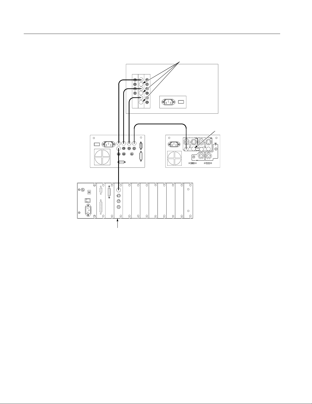
Performance Verification
75 Ω coaxial cable
75 Ω terminator
Pr
Y
Pb
HDM1120J HDTV
Picture Monitor
rear panel
75 Ω coaxial cable
WFM1125 Waveform
Monitor Option 0C
rear panel
75 Ω coaxial cable
HDVG1 module
Figure 4- 1: SDI correctness and digital audio output check connection
Setup. Set the digital TV waveform monitor as indicated below:
75 Ω terminator
764 Digital Audio
Monitor rear panel
TG2000 Signal Generation
Platform rear panel
4- 6
Input .......................... CHA
Display......................... Parade
Format ......................... 240M/274M (for SMPTE 274M) (Opt 0C)
Interlaced/Progressive .............. Interlaced(Opt0D)
Procedure.
1. Select the 75% SMPTE Color Bars signal as follows:
a. Push the Signal Sets button on the TG2000 Signal Generation Platform.
b. Touch 1920X1080 60 2:1 on the display. Load from floppy if necessary.
HDVG1 HDTV Digital Video Generator Service Manual
Page 65

Performance Verification
c. Touch Color Bars on the display until the 75% SMPTE Color Bars
signal is selected.
2. Enter the text and turn on the text overlay as follows:
a. Touch Active Signal Parameters on the display.
b. Touch Text Overlay on the display.
c. Touch Edit Text on the display.
d. In the text entry window, touch the o, v, e, r, l, a, y,andOK in that
order.
e. Touch Text On/Off to turn on the text overlay.
f. Save the text overlay when prompted.
3. Set the audio frequency for the channel 1 and channel 2 to 1 kHz as follows:
a. Press the Test Signal button on the TG2000 Signal Generation Platform.
b. Touch Module Parameters on the display.
c. Touch Embedded Audio on the display.
d. Touch Group1 on the display.
e. Touch the list box for the channel 1. A list box appears for you to select
the desired frequency.
f. Select 1000 Hz using the cursor keys and the Select button.
g. Perform steps c and d for the channel 2.
4. Check the displayed waveform and CRC error:
a. Confirm that t he waveform and “overlay” text are correctly displayed on
the digital TV waveform monitor.
b. Check that the CRC ERROR LED on the digital TV waveform monitor
does not light.
5. Check the digital audio:
a. On the digital audio monitor front panel, press t he MENU button to
display the menu.
b. Select the Input item from the menu, and select CH1--2 input:
BNC--unbalanced item from the submenu.
c. On the digital audio monitor front panel, press the CLEAR button t o
clear the menu.
HDVG1 HDTV Digital Video Generator Service Manual
4- 7
Page 66

Performance Verification
d. On the digital audio monitor front panel, press the CH STATUS button
to display CHANNEL STATUS view.
e. In the view, check CRC errors are not displayed.
f. On the digital audio monitor front panel, press the Audio View button.
g. Check that the digital audio monitor bar graphs show both Channel 1
and Channel 2 at --20 dBfs.
6. Check that the correct color bar and “overlay” text are displayed on the
HDTV picture monitor.
7. Change the coaxial cable connection from OUTPUT 1 connector to
OUTPUT 2 connector on the HDVG1 Generator module and repeat step 4
andstep5.
8. Change the coaxial cable connection from OUTPUT 2 connector to
OUTPUT 3 connector on the HDVG1 Generator module and repeat step 4
andstep5.
Eye Pattern Check
Equipment
required
Two 75 Ω coaxial cables
One AMT75
Two SMA-to-BNC adapters
Sampling oscilloscope with sampling head
Connections. Refer to Figure 4--2 for connections.
Use the AMT75, 75
Ω coaxial cables, and SMA-to-BNC adaptors to make the
following connections:
NOTE. Some sampling oscilloscopes do not automatically adjust their readouts
to account for the
5 attenuation of t he AMT75. You must remember to account
for this attenuation while viewing the oscilloscope readouts if you are using an
oscilloscope of this type.
H Connect the OUTPUT 1 connector on the HDVG1 Generator module to the
AMT75 and then to the CH1 input connector on the oscilloscope sampling
head.
H Connect the OUTPUT 2 connector on the HDVG1 Generator module to the
TRIGGER INPUTS DIRECT connector on the oscilloscope sampling head.
4- 8
HDVG1 HDTV Digital Video Generator Service Manual
Page 67

75 Ω coaxial cable
Performance Verification
TG2000 Signal Generation Platform rear panel
HDVG1 module
Figure 4- 2: Eye pattern check connection
Setup. Set the sampling oscilloscope as indicated below:
11801C Sampling
Oscilloscope
BG1 module
75 Ω coaxial cable
ANT75
TRIGGER INPUTS
DIRECT
Vertical......................... CH1
Coupling.................... AC
Scale ...................... 20mV/div
Horizontal
Sweep ..................... 200ps/div
Trigger
Source ..................... ExternalDirect
Coupling.................... AC
Slope ...................... Positive
Level ...................... 0V
Mode ...................... Auto
Displaymode .................... ColorGradingorInfinite
SMA-to-BNC adaptor
SMA-to-BNC adaptor
procedure.
1. Select the 75% SMPTE Color Bars signal as follows:
a. Push the Signal Sets button on the TG2000 Signal Generation Platform.
b. Touch 1920X1080 60 2:1 on the display.
c. Touch Color Bars on the display until the 75% SMPTE Color Bars
signal is selected.
HDVG1 HDTV Digital Video Generator Service Manual
4- 9
Page 68

Performance Verification
2. Check that OUTPUT 1 eye pattern displayed on the sampling oscilloscope is
fully open. Figure 4--3 shows an example of the eye pattern for an acceptable
output signal
4- 10
Figure 4- 3: Example of eye pattern for an acceptable output signal
3. Use the sampling oscilloscope measurement functions to perform the
amplitude, rise and fall time measurement and check that these values are as
follows.
Amplitude : approximately 800 mV
Rise and fall time : < 270 ps (20% to 80%)
Alignment jitter : < 135 ps
4. Change the cable connection on the HDVG1 Generator Module.
a. Disconnect the coaxial cable from OUTPUT 1 connector on the HDVG1
Generator module.
HDVG1 HDTV Digital Video Generator Service Manual
Page 69

Performance Verification
b. Disconnect the coaxial cable from OUTPUT 2 connector on the HDVG1
Generator module, and then connect it to OUTPUT1 connector on the
HDVG1 Generator module.
c. Connect the coaxial cable disconnected in step 4.a. to OUTPUT 2
connector on the HDVG1 Generator module.
5. Check that OUTPUT 2 eye pattern displayed on the sampling oscilloscope is
fully open (see Figure 4--3 ) and repeat step 3.
6. Disconnect the coaxial cable from OUTPUT 2 connector on the HDVG1
Generator module, and then connect it to OUTPUT 3 connector on the
HDVG1 Generator module.
7. Check that OUTPUT 3 eye pattern displayed on the sampling oscilloscope is
fully open (see Figure 4--3 ) and repeat step 3.
Trigger Output Check
HDVG1 module
Equipment
required
75 Ω coaxial cable
75 Ω terminator
Oscilloscope
Connections. Refer to Figure 4--4 for connections.
Use the 75 Ω coaxial cable and 75 Ω terminator to make the following connections:
H Connect the TRIG OUT connector on the HDVG1 Generator Module to the
oscilloscope CH1 input connector.
TG2000 Signal Generation Platform rear panel
TDS740D Oscilloscope
75 Ω coaxial cable
Figure 4- 4: Trigger output check connection
HDVG1 HDTV Digital Video Generator Service Manual
75 Ω terminator
4- 11
Page 70

Performance Verification
Setup. Set the oscilloscope as indicated below:
Vertical......................... CH1
Coupling.................... DC
Scale ...................... 0.2V/div
Horizontal
Sweep ..................... 1ms/div
Trigger
Coupling.................... AC
Slope ...................... Positive
Level ...................... 0V
Mode ...................... Auto
procedure.
1. Select the 75% SMPTE Color Bars signal as follows:
a. Push the Signal Sets button on the TG2000 Signal Generation Platform.
Instrument Restore from
Backup
b. Touch 1920X1080 60 2:1 on the display.
c. Touch Color Bars on the display until the 75% SMPTE Color bars
signal is selected.
2. Generate the trigger signal as follows:
a. Touch Module Parameters on the display.
b. Touch Trigger on the display.
c. Touch Type to select Horizontal, Vertical,orPixel.
3. Use the oscilloscope measurement functions to perform the trigger output
signal amplituide and rise and fall time measurement and check that these
values are as follows.
Amplitude:
Low : < 0.25 V
High : > 1.0 V
Rise and fall time : < 10 ns
If you performed an instrument backup before beginning the Performance
Verification procedure, restore the signals by following these steps:
4- 12
1. Insert the Troubleshooting disk supplied with this manual into the mainframe
disk drive and press the front-panel Sequences key.
2. Select the tgrstore.seq file, and then touch Start Load.
HDVG1 HDTV Digital Video Generator Service Manual
Page 71

Performance Verification
3. When you see the message, “The Load is Complete”, touch OK.
4. Touch Quit, and then touch Quit again.
5. Touch Sequences and then select the tgbackup.seq file to run (use the touch
screen and the Select key). Be sure this file name appears in the box at the
top of the window.
6. Touch Run. Insert any of the backup disks that you created when you
performed the Instrument Backup procedure. Touch Quit.
7. Insert another disk and touch Quit each time you are prompted. (You can
insert the disks in any order.)
8. When the Restore Complete window appears, turn the mainframe power off
and then on again to cycle power.
Recall Preset
Recall the preset you created as follows:
1. Push the Presets button.
2. Touch Presets on the display.
3. Use the Navigation arrows to move the cursor to the preset that you created
before beginning the Performance Verification procedure. Press the Select
key.
4. Touch Recall. Your instrument settings are recalled.
This completes the Performance Verification procedure. If you require further
assistance, contact your nearest Tektronix Service Center.
HDVG1 HDTV Digital Video Generator Service Manual
4- 13
Page 72

Performance Verification
4- 14
HDVG1 HDTV Digital Video Generator Service Manual
Page 73

Maintenance
Page 74

Page 75

Maintenance
This section contains instructions and procedures for maintaining the HDVG1
Generator module. For information on servicing the mainframe, refer to the
TG2000 Signal Generation Platform Service Manual.
The following information can be found in this section:
H Preparation page 5--1
H Inspection and Cleaning (preventive maintenance) page 5--3
H Repackaging instructions page 5--3
H Removal and replacement procedures page 5--7
H Troubleshooting procedures page 5--9
If the instrument does not function properly, troubleshooting and corrective
measures should be taken immediately to prevent additional problems.
NOTE. Contact your local Tektronix representative for information on where to
return your instrument if it requires repair during the warranty period.
Preparation
Please read and follow these preparation instructions before attempting to
perform any maintenance or service to the instrument.
Servicing Prerequisites
HDVG1 HDTV Digital Video Generator Service Manual
Make sure of the following before beginning any instrument service:
H The maintenance or service of this instrument must be performed by
qualified service personnel only.
H Read the Service Safety Summary located at the beginning of this manual
before attempting to perform any maintenance or service to the instrument.
H Read the Operating Information section of this manual before attempting to
perform any maintenance or service to the instrument.
5- 1
Page 76

Maintenance
Electrostatic Damage
Prevention
This instrument contains electrical components that are susceptible to damage
from electrostatic discharge. Static voltages of 1 kV to 30 kV are common in
unprotected environments.
CAUTION. Static discharge can damage any semiconductor component in this
instrument.
Observe the following precautions to avoid static damage:
H Minimize handling of static-sensitive components.
H Transport and store static-sensitive components or assemblies in their
original containers, on a metal rail, or on conductive foam. Label any
package that contains static-sensitive assemblies or components.
H Discharge the static voltage from your body by wearing a wrist strap while
handling these components. Servicing static-sensitive assemblies or
components should only be performed at a static-free workstation by
qualified personnel.
H Nothing capable of generating or holding a static charge should be allowed
on the workstation surface.
H Keep the component leads shorted together whenever possible.
H Pick up components by the body, never by the leads.
H Do not slide the components over any surface.
H Avoid handling components in areas that have a floor or work surface
covering capable of generating a static charge.
H Use a soldering iron that is connected to earth ground.
H Use only special antistatic, suction-type or wick-type desoldering tools.
NOTE. A 2% RMA flux content solder is recommended for making repairs in this
instrument. Cleaning of rosin residue is not recommended. Most cleaning
solvents tend to reactivate the rosin and spread it under components where it
may cause corrosion under humid conditions. The rosin residue, if left alone,
does not exhibit these corrosive properties.
5- 2
HDVG1 HDTV Digital Video Generator Service Manual
Page 77

Inspection and Cleaning
Preventive maintenance consists of cleaning, visual inspection, performance
checking, and, if needed, readjustment. The preventive maintenance schedule
established for the instrument should be based on the environment in which it is
operated and the amount of use. Under average conditions, scheduled preventive
maintenance should be performed every 2000 hours of operation.
Maintenance
General Care
Cleaning and Visual
Inspection
Performance Verification
Protect the module from adverse weather conditions. The module is not
waterproof.
CAUTION. To avoid damage to this module, do not expose it to sprays, liquids, or
solvents. Do not flex the circuit board if you remove the board from its mounting
shield. The circuit board can be damaged by flexing. The shield provides
necessary structural support to the circuit board.
Clean the mainframe and modules often enough to prevent dust or dirt from
accumulating. Refer to Cleaning and Visual Inspection in the TG2000 Signal
Generation Platform Service Manual.
Check module performance after each 2000 hours of operation or every
12 months. This will help to ensure maximum performance and assist in locating
defects that may not be apparent during regular operation. Performance
verification procedures are included in this m anual.
Repackaging Instructions
Use the following instructions to prepare your instrument for shipment t o a
Tektronix, Inc., Service Center:
1. Attach a tag to the instrument showing: the owner, complete address and
phone number of someone at your firm who can be contacted, the instrument
serial number, and a description of t he required service.
2. Package the instrument in the original packaging materials. Figures 5--1 and
5--2 illustrate how to repackage the module in the original packaging
materials. If the original packaging materials are not available, follow these
directions:
a. Obtain a carton of corrugated cardboard having inside dimensions six or
more inches greater than the dimensions of the instrument. Use a
shipping carton that has a test strength of at least 250 pounds (113.5 kg).
b. Surround the module with a protective (anti-static) bag.
HDVG1 HDTV Digital Video Generator Service Manual
5- 3
Page 78

Maintenance
c. Pack dunnage or urethane foam between the instrument and the carton. If
using Styrofoam kernels, overfill the box and compress the kernels by
closing the lid. There should be three inches of tightly packed cushioning on all sides of the instrument.
3. Seal the carton with shipping tape, industrial stapler, or both.
004-4712-00
Module
Figure 5- 1: Placing the module in t he protective wrapping
5- 4
HDVG1 HDTV Digital Video Generator Service Manual
Page 79

004-4712-00
Maintenance
004-4713-00
2Each
004-0828-00
Figure 5- 2: Placing the module in the shipping carton
HDVG1 HDTV Digital Video Generator Service Manual
5- 5
Page 80

Maintenance
5- 6
HDVG1 HDTV Digital Video Generator Service Manual
Page 81

Removal and Replacement
This section contains the instructions on how you can remove and replace the
customer replaceable parts of the HDVG1 Generator module.
Tools Required
The following tools are required to perform the removal and replacement
procedures:
Table 5- 1: Required tools
Tool Use
Torx screwdriver handle Removing the module from the mainframe
T-10 Torx tip Removing the module from the mainframe
9/16 inch box wrench Removing the rear panel
Removing the Rear Panel
To remove the rear panel from a module, perform the following steps:
1. Perform Signal Backup and Logo Backup on page 2--8.
2. Use the Module Removal procedure on page 2--9 to remove the HDVG1
3. Remove the nuts and washers from each of the rear panel BNC connectors.
4. Lift the rear panel away from the module.
5. To replace the rear panel, position it on the module, install the lock washers
6. Tighten the nuts.
7. Restore signals and logos.
Generator module from the mainframe.
and then the nuts.
HDVG1 HDTV Digital Video Generator Service Manual
5- 7
Page 82

Removal and Replacement
Replacing the Shield
It is usually not necessary to remove the shield. If you are returning the HDVG1
Generator module to Tektronix for service, do not remove the shield. Return the
entire module.
If you need to replace a damaged shield, carefully follow these instructions.
CAUTION. The shield provides important support and protection for the
surface-mount components. If you remove the shield, be sure not to flex the
circuit board.
1. Perform Removing the Rear Panel on page 5--7.
2. Using the T-10 Torx tip, remove the eight screws that attach the HDVG1
circuit board to the shield.
3. Using great care not to bend or flex the circuit board, pull it out until the
BNC connectors clear the rear portion of the shield. Remove the circuit
board from the shield and place it on a static free surface.
4. Set the replacement shield assembly (which includes a metal portion and a
plastic portion) on a firm, flat, static-free work surface. Carefully place the
circuit board in place on the shield.
5. Install and tighten the eight screws that you removed in step 2. Check that
the circuit board is flat and is not flexed.
CAUTION. When installing the circuit board onto the shield, make sure both the
shield and the circuit board are flat. If the board is flexed or warped, it may
damage sensitive surface-mount components.
6. Reinstall the rear panel.
Replacing the Rear Panel Connectors
It is usually not necessary to replace the rear panel connectors (shown in the
Replaceable Parts List, Figure 10-1-3 and 10-1-4). However, if a connector
becomes damaged, you can replace it by performing the following steps:
1. Refer to the preceding instructions, Replacing the Shield, to remove the
shield from the HDVG1 Generator module.
2. Disconnect the connector cables from J800 on the A10 circuit board, CN2,
CN3, and CN4 on the serializer.
5- 8
3. Remove the damaged connector from the real panel.
4. To replace the connector, reverse the procedure.
HDVG1 HDTV Digital Video Generator Service Manual
Page 83

Troubleshooting Procedures
This section contains instructions and procedures for troubleshooting the
HDVG1 Generator module. These procedures will help you decide whether it is
necessary to replace your module.
If the TG2000 Platform mainframe does not boot up or if the display is not
working, refer to Troubleshooting in the TG2000 Signal Generation Platform
Service Manual.
Equipment Required
The equipment listed in Table 5--2 is required for troubleshooting.
Table 5- 2: Equipment required for troubleshooting
Equipment description Minimum requirements/example
Torx screwdriver handle Accepts Torx-driver bits
T-10 Torx tip Torx-driver bit for T-10 screw head
Blank disks MS--DOS preformatted, 3.5 inch.
Troubleshooting disk Supplied with the TG2000 Signal Generation Platform Service
Voltmeter with probes Accurate to two decimal places, able to measure AC voltage of
For instrument backup, you will need approximately one disk for
each installed generator module. To write the console ring file, you
will need two disks.
Manual
900 V
For example, Tektronix DM2510 Digital Multimeter
RMS.
HDVG1 HDTV Digital Video Generator Service Manual
5- 9
Page 84

Troubleshooting Procedures
General Troubleshooting
This section contains general troubleshooting instructions and procedures to use
when you begin to troubleshoot suspected faults with the HDVG1 Generator
module.
Signal Backup
Saving the Console Ring
File to Disk
Before you begin any troubleshooting procedures, perform Signal Backup and
Logo Backup on page 2--8. After the problem is solved, restore instrument
signals from the backup disks.
CAUTION. T o prevent data loss, back up the instrument before you begin any
troubleshooting procedures.
The TG2000 Platform mainframe displays module diagnostic information
during instrument power up. Any error messages are written to an internal file
called the console ring file. Tektronix technicians can use the information in the
console ring file to help troubleshoot a malfunctioning module.
NOTE. Write the console ring file to disk before performing troubleshooting to
prevent the troubleshooting routines from overwriting the console ring file.
Write the file as follows:
1. Load the Troubleshooting disk (supplied with the TG2000 Signal Generation
Platform Service Manual) into the floppy drive. Press the front-panel
Sequences button.
5- 10
2. Touch File Utilities, and then touch Add Sequences from Disk.
3. Select the consbak.seq sequence file and then touch Start Load.
4. Touch OK, Quit,andthenQuit again.
5. Touch Sequences and then select the consbak.seq file to run (use the Select
key).
6. Touch Run. Insert a blank disk when prompted, and touch Quit. Label this
disk #1.
7. Turn the i nstrument off and then back on from the front panel. Wait until the
instrument has completed its power up process.
8. Write the console ring file to disk again, using a different disk. Label this
disk #2.
HDVG1 HDTV Digital Video Generator Service Manual
Page 85

Troubleshooting Procedures
9. Read the console ring file power up messages. If there are HDVG1
Generator module errors, refer to the Fault Symptom Table on page 5--11.
10. If the TG2000 Platform does not display any power-up confidence test
messages, or the CPU module fails the confidence test, refer to Trouble-
shooting in the TG2000 Signal Generation Platform Service Manual.
Returning Modules to
Tektronix
Fault Symptom Table
When you return a mainframe or module to Tektronix for repair or replacement,
be sure to include the following:
H The disks containing the console ring files
H Whether or not the module passed diagnostics, the highest number
reached for that module, and any error messages
H Description of the problem, including which troubleshooting flow chart
you used
Use this fault symptom table after you have performed the preceding General
Troubleshooting. Before proceeding, it is important to save the console ring file
as indicated in General Troubleshooting on page 5--10.
Locate your fault symptom in Table 5--3 and go to the flowchart indicated.
Table 5- 3: Fault symptom table
Symptom Flowchart
Major difficulties with module page 5--12
with module installed in current slot page 5--13
with module moved to different slot page 5--14
Mainframe fails to power up page 5--15
Signals lost after power down page 5--16
Wrong signal on output page 5--17
Missing output signal page 5--18
HDVG1 HDTV Digital Video Generator Service Manual
5- 11
Page 86

Troubleshooting Procedures
Troubleshooting Flowcharts
The troubleshooting flowcharts provide a series of steps to help you determine
whether the HDVG1 Generator module is faulty. Each chart relates to an entry in
Table 5--3.
If you recently upgraded any TG2000 or module firmware,
check that you did not accidentally delete the HDVG1
If you accidentally deleted the HDVG1 firmware, reload
Use this procedure when the
mainframe does not recognize
the module or does not pass
power-up confidence tests.
firmware.
the HDVG1 Module firmware.
Does the module
appear in the “slots
occupied” list during
power--up?
No
Yes
Does the
TG2000 recog-
nize the HDVG1
module?
No
Yes
Does the
HDVG1 module
pass
Confidence
tests?
No
Yes
TG2000 now recognizes the HDVG1 module.
HDVG1 module now passes power-up
confidence and self-calibration tests.
Figure 5- 3: Flowchart for major difficulties with module
Go to flowchart
on page 5--13.
5- 12
HDVG1 HDTV Digital Video Generator Service Manual
Page 87

Continuation of flowchart from
page 5--12.
Troubleshooting Procedures
Use the Module Removal procedure on page 5--7 to remove the
Check for bent or damaged pins on the three Backplane board
connectors (P1, P2, and P3). Carefully straighten any bent pins.
Check that all module subassemblies and socketed parts are
seated properly. Reinstall the module in the same slot.
Set the rear-panel power switch to on, and then use the
front-panel switch to turn the instrument on.
Watch the display for the HDVG1 Confidence Tests. Note
whether the HDVG1 module passed the diagnostic.
affected module.
Note the highest number to appear.
Does the
TG2000 recog-
nize the HDVG1
module?
No
Yes
Does the
HDVG1 module
pass Confidence
tests?
No
Yes
Go to flowchart
on page 5--14.
TG2000 now recognizes the HDVG1 module.
HDVG1 Module now passes power-up
confidence tests.
Figure 5- 4: Flowchart for checking the current module installation slot
HDVG1 HDTV Digital Video Generator Service Manual
5- 13
Page 88
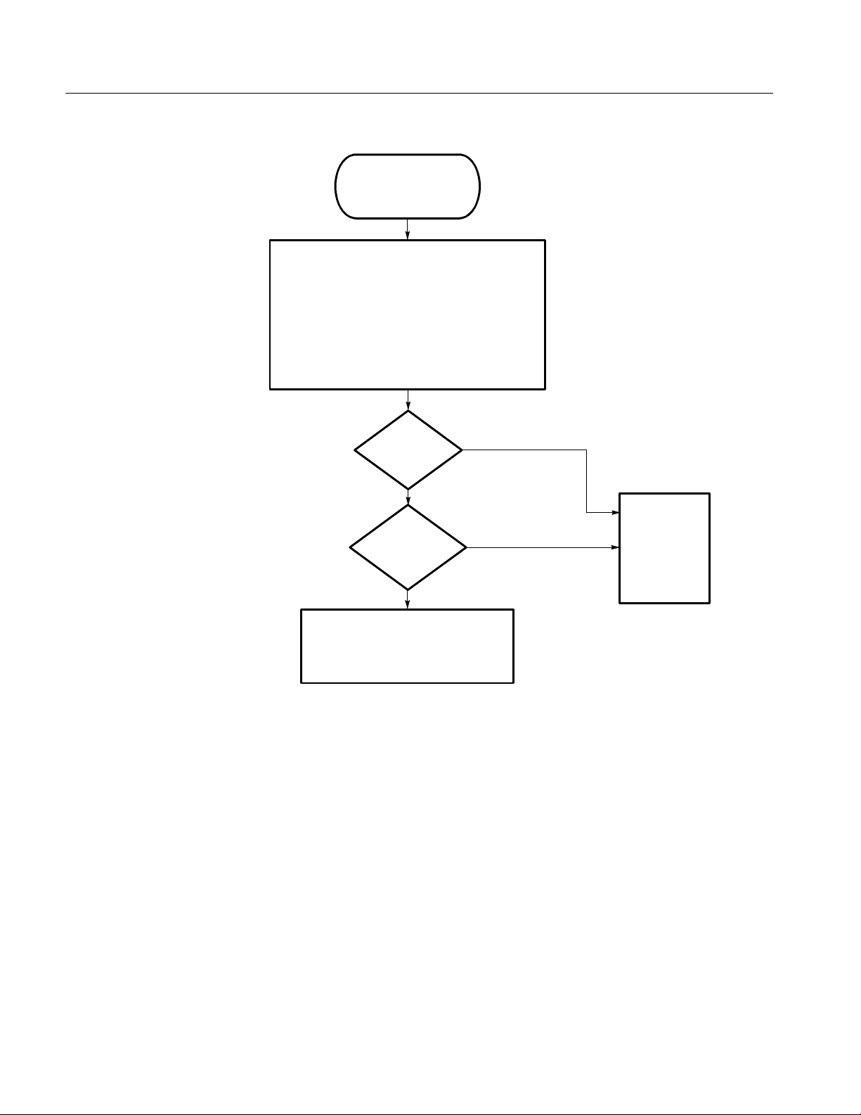
Troubleshooting Procedures
Continuation of flowchart from
page 5--13.
Use the Module Removal procedure on page 5--7 to remove
Install the HDVG1 module in a different slot.
Set the rear-panel power switch to on, and then use the
front-panel switch to turn the instrument on.
Watch the display for the HDVG1 Confidence Tests. Note
whether the HDVG1 module passed the diagnostic.
the affected module.
Note the highest number to appear.
Does the
TG2000 recog-
nize the HDVG1
module?
No
Yes
Does the
HDVG1 module
pass Confidence
tests?
No
Yes
HDVG1 Module OK
Note that there may be a problem with the
Backplane board. Record troubleshooting
information and contact Tektronix.
Replace the
module.
5- 14
Figure 5- 5: Flowchart for checking the module in a different slot
HDVG1 HDTV Digital Video Generator Service Manual
Page 89

Use this procedure when
the TG2000 Platform
mainframe fails to power up
and you suspect the
HDVG1 module.
Set the rear-panel power switch to off, then on, and then
use the front-panel switch to turn the instrument on.
Watch the display for the HDVG1 Confidence Tests. Note
whether the HDVG1 module passed the diagnostic. Note
the highest number to appear.
Troubleshooting Procedures
Did the
HDVG1 fail
confidence
tests?
No
Yes
Use the Module Removal procedure on page 5--7 to
Set the rear-panel power switch to off, then on, and then
use the front-panel switch to turn the instrument on.
remove the HDVG1 module.
Did the
mainframe power
up successfully?
No
Yes
Install the HDVG1 module in a different slot.
Set the rear-panel power switch to on, and then use the
front-panel switch to turn the instrument on.
Watch the display for the HDVG1 Confidence Tests. Note
whether the HDVG1 module passed the diagnostic.
Note the highest number to appear.
The problem is probably in another
module. Refer to Troubleshooting in the
TG2000 SIgnal Generation Platform
Service Manual.
The problem is probably in another
module. Refer to Troubleshooting in the
TG2000 SIgnal Generation Platform
Service Manual.
Did the HDVG1
still fail confidence
tests?
Replace the module.
Figure 5- 6: Flowchart for failure to power up
HDVG1 HDTV Digital Video Generator Service Manual
Yes
No
There may be a problem with the
Backplane board. Record
troubleshooting information and
contact Tektronix.
5- 15
Page 90

Troubleshooting Procedures
Use this procedure when your
module’s signals are lost after
powering down the mainframe
from the rear-panel power switch.
Check that the backup battery
wires are connected.
Turn off the rear-panel power
switch and measure the backup
battery voltage (+4.2 V).
Is the battery
voltage ok?
No
Yes
Use the Module Removal procedure on page 5--7
to remove the faulty module.
Check that the Backplane board pins are
not bent on the affected module.
Move the affected module to another slot.
Does the affected
module operate in
the new slot?
.
Yes
There may be a problem with
the Backplane board. Record
troubleshooting information
and contact Tektronix.
No
Replace the module.
Check Power Supply charging circuit.
RemovethecablefromJ2onthePower
Supply board and measure pin 7 (See
Figure 5--8) for +4.7 V with rear panel
power on, +0.5 V with rear-panel power off.
Is the battery
charging circuit
ok?
Yes
No
Refer to the TG2000 Service
Manual for instructions to replace
the Power Supply module.
The problem is probably the
backup battery, but it could
be the Backplane board or
the CPU module. Record
troubleshooting information
and contact Tektronix.
Figure 5- 7: Flowchart for signals lost after power down
5- 16
HDVG1 HDTV Digital Video Generator Service Manual
Page 91

Troubleshooting Procedures
Power Supply
Indicator LEDs
board
J2
OT OV
OI +5V
Pin 7
OT -- Over temperature
OV -- Over voltage
OI -- Over current
Figure 5- 8: Measuring the battery charging circuit
Line Filter board
Use this procedure when
you get the wrong or a
distorted signal on the
output.
Make sure you are using
the correct video standard,
monitoring equipment, and
signal.
Is the signal still
wrong?
No
Yes
Reload test signal
from disk.
Replace affected
module.
Figure 5- 9: Flowchart for wrong signal on output
HDVG1 Module OK
HDVG1 HDTV Digital Video Generator Service Manual
5- 17
Page 92

Troubleshooting Procedures
Use this procedure when you
do not have an output signal.
Make sure the module
output is enabled.
Make sure the signal sets are
installed. For example, if you
ordered a module separately
and added it to your TG2000
Platform mainframe, you need
to load the signals from the
supplied disks. Refer to Signal
Set Installation on page 2--6.
Is the signal still
missing?
No
HDVG1 Module OK
Yes
Replace affected
module.
Figure 5- 10: Flowchart for missing output signal
5- 18
HDVG1 HDTV Digital Video Generator Service Manual
Page 93

Option
Page 94

Page 95

Option
Option D1 Description
This section describes option that is available for the HDVG1 Generator module.
The following option is available.
H Option D1 ships with test result report.
A calibration data test result report will be provided with the HDVG1 Generator
module when this option is specified.
HDVG1 HDTV Digital Video Generator Service Manual
6- 1
Page 96

Option
6- 2
HDVG1 HDTV Digital Video Generator Service Manual
Page 97

Diagram
Page 98

Page 99

Diagram
Figure 7--1 shows the HDVG1 Generator module and how it interconnects with
the TG2000 Signal Generation Platform.
Diagrams showing mainframe component interconnections, such as power
supply and clock, can be found in the TG2000 Signal Generation Platform
Service Manual.
A block diagram of the HDVG1 Generator module is located in the Theory of
Operation section, beginning on page 3--1.
Rear-panel
connectors
OUTPUT 1
OUTPUT 2
OUTPUT 3
TRIGGER
J800
A10
HDVG1 module
P1A, P1B,
P1C, P1D
P3A, P3B
Figure 7- 1: HDVG1 Generator module connections
P2
128
14
30
A1
Backplane board
Slot 2 - 10
J1
J2
J3
HDVG1 HDTV Digital Video Generator Service Manual
7- 1
Page 100

Diagram
7- 2
HDVG1 HDTV Digital Video Generator Service Manual
 Loading...