

Page 1

HDMXpress 2.1
Printable Application Help
*P077159601*
077-1596-01
Page 2

Page 3

HDMXpress 2.1
Printable Application Help
www.tek.com
077-1596-01
Page 4

Copyright © Tektronix. All rights reserved. Licensed software products are owned by Tektronix or its subsidiaries
or suppliers, and are protected by national copyright laws and international treaty provisions. Tektronix products
are covered by U.S. and foreign patents, issued and pending. Information in this publication supersedes that in all
previously published material. Specifications and price change privileges reserved.
TEKTRONIX and TEK are registered trademarks of Tektronix, Inc.
Contacting Tektronix
Tektronix, Inc.
14150 SW Karl Braun Drive
P.O. Box 500
Beaverton, OR 97077
USA
For product information, sales, service, and technical support:
■
In North America, call 1-800-833-9200.
■
Worldwide, visit www.tek.com to find contacts in your area.
Page 5

Table of Contents
Welcome ............................................................................................................................................. iii
Introduction
Conventions .................................................................................................................................... 1
Getting started
Minimum system requirements ...................................................................................................... 3
Installing the software .................................................................................................................... 3
Activate the license ......................................................................................................................... 4
View version and license information ............................................................................................ 4
Connection setup ............................................................................................................................ 5
Operating basics
Starting the software ....................................................................................................................... 9
Exiting the software ...................................................................................................................... 10
File name extensions .................................................................................................................... 10
Menus and toolbars ....................................................................................................................... 10
Menu bar .................................................................................................................................. 10
Configuration ........................................................................................................................... 13
Configuration list ..................................................................................................................... 15
Instrument Control .................................................................................................................. 16
Output ...................................................................................................................................... 17
AWG-HD Deskew
AWG-HD Deskew Using HDMXpress ........................................................................................ 20
Reference
Shortcut keys ................................................................................................................................ 29
Parameters values ......................................................................................................................... 29
HDMXpress 2.1 Printable Application Help i
Page 6

Table of Contents
ii HDMXpress 2.1 Printable Application Help
Page 7
Welcome
The HDMXpress 2.1 is a HDMI pattern generation and calibration software that
runs on the Arbitrary Waveform Generator. HDMXpress 2.1 supports different
FRL electrical patterns LTP and RXSB33PAT at different FRL rates. It also
supports closed loop calibration for differential amplitude, inter-pair skew, intrapair skew, FRL rate and jitter tolerance tests. Once the calibration is completed,
the application automatically transfers the waveforms across all the AWGs.
Key Features
■
Supports 3 and 4 Lane.
■
Synchronizes the patterns created in the HDMXpress to the TekExpress FRL
solution.
■
Supports closed loop calibration and creates patterns for electrical testing.
■
Supports differential amplitude Swing, Intra-pair skew, Inter-pair skew,
Minimum Link rate and Jitter Calibration.
■
Supports multilane calibration for HFR2-5 measurement.
HDMXpress 2.1 Printable Application Help iii
Page 8

Welcome
iv HDMXpress 2.1 Printable Application Help
Page 9

Introduction
Conventions
The online help uses the following conventions:
■
When steps require a sequence of selections using the software interface, the
">" delimiter marks each transition between a menu and an option. For
example, File > Save.
■
DUT refers to the Device Under Test.
■
The terms "waveform" and "signal" are used interchangeably.
■
The term AWG refers to a Tektronix Arbitrary Waveform Generator.
HDMXpress 2.1 Printable Application Help 1
Page 10

Introduction
2 HDMXpress 2.1 Printable Application Help
Page 11
Getting started
Minimum system requirements
The minimum requirements of the HDMXpress 2.1 application are listed in the
following table:
Table 1: Minimum system requirements
Component Description
Supported OS Windows 10 Professional
Minimum Requirements More than 8 GB free disk space
.Net 4.0
Matlab® Compiler Runtime version 8.0
Prerequisites
Installing the software
TekVisa is required to establish the communication with the signal generators (or
other test instruments), over a LAN. You can download and install the software
from www.tek.com.
An installation wizard installs HDMXpress 2.1. If you have not installed
MATLAB Runtime and .NET 4.0, the installer will detect and install it.
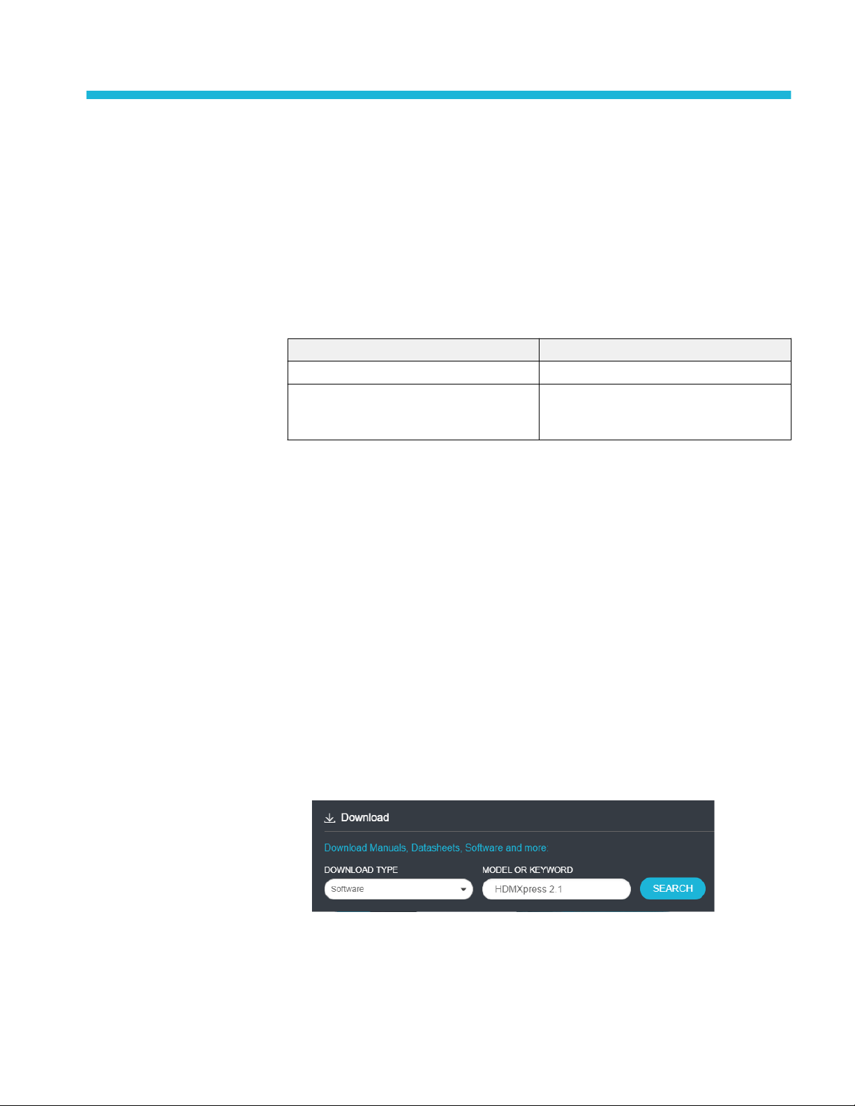
Complete the following steps to download and install the latest HDMXpress
2.1 application. See Minimum system requirements for compatibility.
1. Go to www.tek.com.
2. Click Downloads. In the Downloads menu, select DOWNLOAD TYPE as
Software and enter HDMXpress 2.1 in the MODEL OR KEYWORD field
and click SEARCH.
3. Select the latest version of software and follow the instructions to download.
Copy the executable file to the oscilloscope.
4. Double-click the executable and follow the on-screen instructions. The
software is installed at C:\Program Files\Tektronix\HDMXpress2.1\.
HDMXpress 2.1 Printable Application Help 3
Page 12
Getting started
Activate the license
NOTE. You must enable option HD21DSM in the oscilloscope to connect to the
AWG where HDMXpress 2.1 is installed.
Activate the license using the option installation wizard on the oscilloscope.
Follow these steps to activate the HDMXpress 2.1 license:
1. From the oscilloscope menu bar, click Utilities > Option Installation.
The TekScope Option Installation wizard opens.
2. Instructions for using the Options Installation window to activate licenses for
installed applications is provided in the oscilloscope online help. Press the F1
key on the oscilloscope keyboard to open the Option Installation help topic.
Follow the directions in the topic to activate the license.
View version and license information
To view version information, Click Help > About HDMXpress 2.1.
Option Information
From the oscilloscope Help menu, select About TekScope.
The Options section in the dialog box displays a list of installed options,
including HDMXpress 2.1 (option HD21DSM).
NOTE. Option HD21DSM must be installed on the oscilloscope. The oscilloscope
is connected to the AWG (where HDMXpress 2.1 is installed) through LAN
network.
Additional Information
For HDMXpress 2.1 to be activated on the AWG, the AWG where the
HDMXpress 2.1 software installed must be connected via the network to an
oscilloscope with option HD21DSM installed.
4 HDMXpress 2.1 Printable Application Help
Page 13

Getting started
Connection setup
NOTE. For HDMXpress to run, the AWG (where the HDMXpress software is
installed) must be connected to an oscilloscope on the network were option
HD21DSM enabled.
Following are the list of tests and setup information for calibrating the waveform:
■
Test ID HFR 2-1: Max Differential Swing Tolerance
■
Test ID HFR 2-2: Intra-Pair Skew
■
Test ID HFR 2-3: Inter-Pair Skew
■
Test ID HFR 2-4: Minimum Link Rate Tolerance
■
Test ID HFR 2-5: Jitter Tolerance
HDMXpress 2.1 Printable Application Help 5
Page 14

Getting started
Figure 1: Connection diagram for Calibrating the AWG waveform (Lane0 to D0 and Lane 1 to
D1)
6 HDMXpress 2.1 Printable Application Help
Page 15

Getting started
Figure 2: Connection diagram for Calibrating the AWG waveform (Lane2 to D2 and Lane 3 to
D3)
HDMXpress 2.1 Printable Application Help 7
Page 16

Getting started
Figure 3: Sink Hub configuration setup
8 HDMXpress 2.1 Printable Application Help
Page 17

Operating basics
Starting the software
From the Start menu, click All Programs > HDMXpress 2.1. You can also
double-click the HDMXpress 2.1 shortcut on the desktop.
HDMXpress 2.1 Printable Application Help 9
Page 18

Operating basics
Exiting the software
File name extensions
Select File > Exit to exit the application.
The application uses the following file name extensions:
Table 2: File name extensions
File name extension Description
.wfm Binary file containing an AWG waveform record in a recallable proprietary
format.
.flt Embed/De-Embed filter coefficient.
.png Schematics and images.
Menus and toolbars
Menu bar
The HDMXpress 2.1 has the following menus:
File Menu
The File menu has the following items:
■
Restore Default Configuration: Restores the default configuration.
■
Open Setup: Opens a saved setup file.
■
Save Setup: Saves the setup file in the .setup format in a folder in your C
drive.
■
Save Setup As: Saves the setup under another name in the .setup format.
■
Exit: Exits the application.
Edit Menu
10 HDMXpress 2.1 Printable Application Help
Page 19

Operating basics
The edit menu has the following items:
■
Delete: Deletes the selected configurations.
■
Select All: Selects all the configurations.
View Menu
The view menu has the following items:
■
Standard Toolbar:
Select to view or hide the toolbar. The Standard toolbar uses icons that
provide a quick access to many frequently used functions. If the toolbar is
hidden before closing the application, it remains hidden when the application
is opened again.
The Standard toolbar has the following options:
■
New Configuration: Creates a new empty template based on the current
settings.
■
Add To Configuration List: The configured pattern is added to the
Configuration list.
■
Delete Configuration: Deletes the selected Pattern from the
Configuration list.
■
AWG-HD Deskew: Click to perform deskew operation of AWG-HD.
( Follow the instructions mentioned in AWG-HD Deskew Using
HDMXpress on page 20 to perform the deskew of all channels of
AWG-HD box)
■
Calibrate: The patterns are calibrated for Lane0 (D0) and the calibrated
parameters are applied across all lanes (AWGs).
NOTE. When multilane calibrate checkbox is enabled, all the AWG's are
calibrated independently.
■
Stop: Stops generating the pattern.
■
Status Bar:
Select to view or hide the status bar. The status bar displays the AWG name
on which the HDMXpress 2.1 is installed. The status bar is displayed by
default. If the status bar is hidden before closing the application, it remains
hidden when the application is opened again.
HDMXpress 2.1 Printable Application Help 11
Page 20

Operating basics
Pattern Menu
The pattern menu has the following items:
■
New: Creates a new empty template file based on current settings.
■
Add to Configuration List: Adds a pattern to the configuration list.
■
Calibrate: The patterns are calibrated for Lane0 (D0) and the calibrated
parameters are applied across all lanes (AWGs).
■
Stop: Stops generating the pattern.
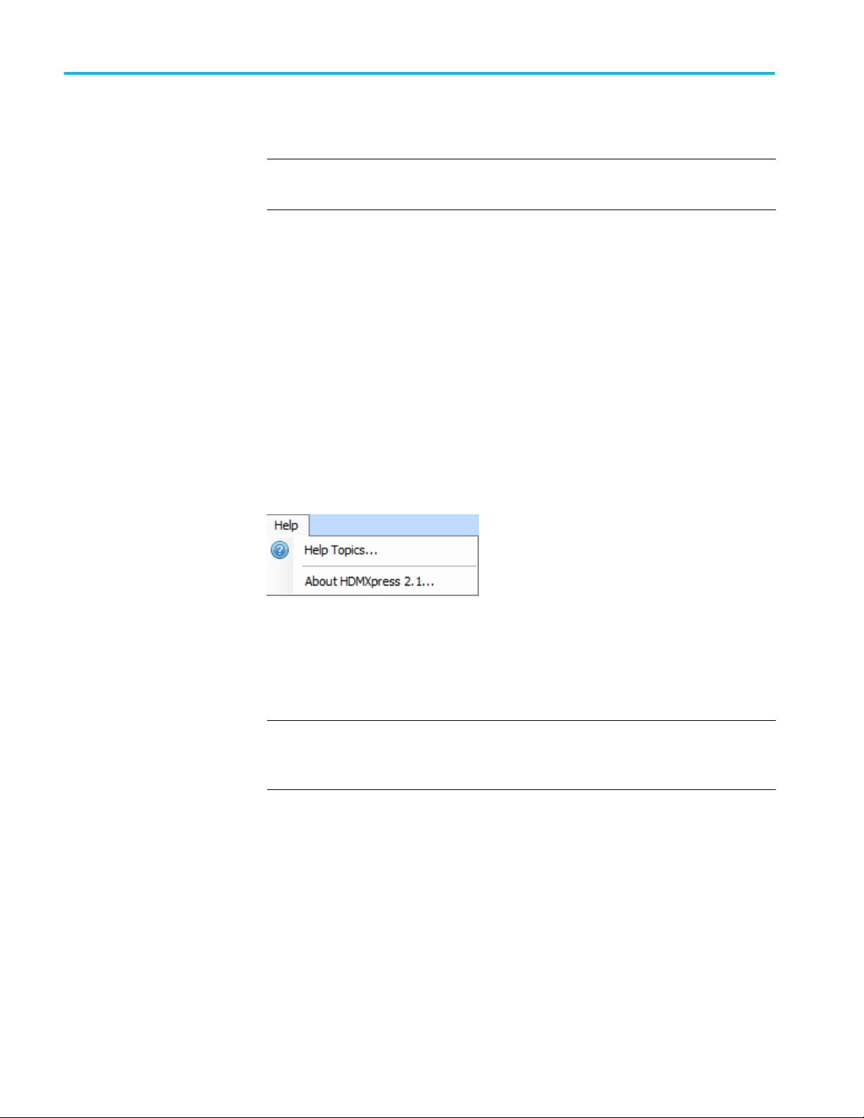
Help Menu
The help menu has the following items:
■
Help Topics: Opens the online help.
■
About HDMXpress 2.1: Displays information about the application, such as
the version number.
12 HDMXpress 2.1 Printable Application Help
Page 21

Operating basics
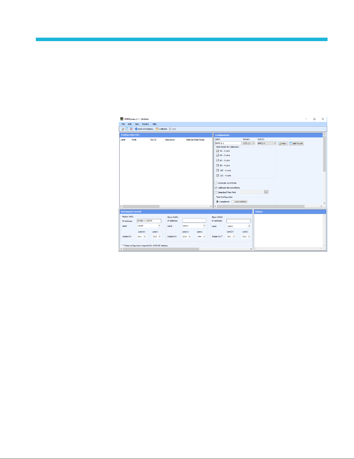
Configuration
The configuration window allows you to select the test measurement settings for
the device under test (DUT) for the calibration of patterns.
Label: Displays the defined test name as HDMI 2.1.
Version: Selects the required CTS Version from the drop-down list. The
available option is 2.1.
Test ID: Selects the test measurement from the drop-down. By default HFR2-1 is
selected.
New: Click to create a new pattern based on the current settings.
Add to list: Click to add pattern to the configuration list.
Data rates for calibration: Selects the data rates from 3 G to 12 G.
Generate waveforms: Generates the new waveforms pattern. The pattern will be
created in all AWGs (master and slave).
Multi-Lane Calibrate: Provides an option to Calibrate for all 4 AWGs used in
FRL Sink tests and generates FRL Patterns in all the 4 AWGs independently. At
a time, two AWGs (Either Lane 0 - Lane 1/ Lane 2 - Lane 3) are calibrated one
after the other without changing the connections of the Oscilloscope.
HDMXpress 2.1 Printable Application Help 13
Page 22

Operating basics
Lane0 should be connected to channel1 & channel2 of the scope and Lane2
should be connected to channel3 & channel4 of the scope.
NOTE. Multi-Lane Calibrate option is applicable only for HFR2-5 Jitter
Tolerance measurement.
Steps to be followed to calibrate waveforms using Multi-Lane Calibrate option:
1. Select the appropriate Data Rates, Test ID, SJ Frequencies.
2. Select the Multi-Lane Calibrate checkbox.
3. Click Add To List; The respective tests are added into the Configuration
List.
4. Click Calibrate checkbox to calibrate the waveforms.
During the calibration, dialog box appears to Connect Lane 0 and Lane 1 AWGs
to the oscilloscope. Refer Figure 1: Connection diagram for Calibrating the
AWG waveform (Lane0 to D0 and Lane 1 to D1) on page 6
Once Lane 0 and Lane 1 AWGs are calibrated, additional dialog box appears to
calibrate Lane 2 and Lane 3 AWG respectively. Refer Figure 2: Connection
diagram for Calibrating the AWG waveform (Lane2 to D2 and Lane 3 to D3) on
page 7
Calibrate the waveforms: Performs the closed loop calibration on the generated
waveforms.
Deembed filter path: Selects the filter file which deembeds the receptacle.
14 HDMXpress 2.1 Printable Application Help
Page 23

Operating basics
Test configuration:
Compliance: Sets default values for electrical configurations as defined by the
CTS specification.
■
Nominal Voltage Swing: Displays output signal amplitude. By default
1000 mV is selected.
■
Maximum Voltage Swing: Displays output signal amplitude. By default
1200 mV is selected.
■
Percentage deviation: Displays percentage of variation in the calibrated
values.
User defined: select to specify the user defined values for electrical
configurations. By default, this option is disabled.
Configuration list
Configuration list displays a list of all the patterns. By default it is displayed and
opens in the leftmost area of the display window.
After you configure the pattern in the Configuration -> New window, select
Add To List. The configured pattern data will be saved and displayed in the
Configuration List window. The Configuration list displays Label, Test ID,
Mode, Description, Selected Data Rates, Generate Pattern and Calibrate
Waveform.
NOTE. You can configure any number of patterns and add them to the
configuration list.
After you select a pattern to generate, you must compile it to create the data.
Once you generate a pattern (using Pattern > Generate from the menu bar), a
pattern is created.
HDMXpress 2.1 Printable Application Help 15
Page 24

Operating basics
To save a configured pattern that is available in the list, select the pattern and
select File > Save Setup As. The configured pattern is saved as a (.setup) file in
the specified location.
After you select a waveform to calibrate, you must compile it to calibrate. Once
you calibrate a waveform (using Calibrate from the toolbar), a waveform is
calibrated.
To save a calibrated waveform that is available in the list, select the waveform
and select File > Save Setup As. The calibrated waveform is saved as a (.setup)
file in the specified location.
NOTE. If you close the application without saving the configured pattern or
Calibrated waveform, the pattern or waveform data is lost. You can compile the
pattern or calibrate the waveform again from the setup, if you have saved the
setup using File > Save Setup or Save Setup As.
You can select multiple contiguous and non-contiguous patterns or waveforms
using the Shift and Ctrl keys, respectively. Selecting multiple configured
patterns or waveforms and selecting the Delete option deletes all the selected
patterns or waveforms. Selecting multiple configured patterns and selecting the
Generate option generates all the pattens for the selected pattern configurations.
Instrument Control
The instrument control window allows you to select and configure the
instruments used in the application.
HDMXpress 2.1 application works with the following arbitrary waveform
generators.
■
AWG70001A
■
AWG70001B
HDMXpress 2.1 creates patterns on Master and Slave AWG. The Clock and
Data0 patterns are created on the Master AWG. Data1, Data2 and Data3 patterns
are created on the Slave AWG. Configure the Slave AWG and Oscilloscope IP
address.
16 HDMXpress 2.1 Printable Application Help
Page 25

Operating basics
Table 3: Instrumental control window settings
Master AWG
Address Enter the Master AWG IP address or GPIB
address. GPIB8::1::INSTR is the default
address.
Lane Select the Lane. By default Lane0 is selected for
the Master AWG.
Scope Channel Selects the oscilloscope channel connected to
'Lane0+' and 'Lane0-' of AWG.
Slave AWG
Address Enter the IP address of the slave AWG.
TCPIP::XXX.XX.XXX.XXX::INSTR is the default
address.
Lane Select the slave AWG Lane. By default Lane1,
Lane2, and Lane3 are selected for Slave AWG1,
Slave AWG2 and Slave AWG3 respectively.
Scope Channel Configure the oscilloscope channel for which
'Lane+' and 'Lane-' are connected.
Scope
IP Address Enter the oscillocope IP address.
GPIB8::1::INSTR is the default address.
AWG/HD
MAC/IP Address Enter the MAC/IP address.
TCPIP::XXX.XX.XXX.XXX::INSTR is the default
address.
Port By default 4000 is selected.
Output
Output window displays all the log messages.
HDMXpress 2.1 Printable Application Help 17
Page 26

Operating basics
18 HDMXpress 2.1 Printable Application Help
Page 27

AWG-HD Deskew
HDMXpress 2.1 Printable Application Help 19
Page 28

AWG-HD Deskew
AWG-HD Deskew Using HDMXpress
Steps to deskew AWG-HD using HDMXpress application:
1. For AWG-HD Deskew refer Figure 1: Connection diagram for Calibrating
the AWG waveform (Lane0 to D0 and Lane 1 to D1) on page 6
2. Enable Sync manually in all the AWGs.
3. Install the HDMXpress application on the Master AWG.
4. Launch the application and check the connections of all 4 AWGs through
TekVisa.
5. Enter the valid IP addresses in the Instrument Control section of the
HDMXpress application.
6. Click AWG-HD Deskew option in the Toolbar.
7. Once the AWG-HD channel 1 is connected to scope then Click Ok.The value
is updated in the “FRLSinkCommonSettingsXML” file. If CH1 Deskew is
not required, click Cancel.
8. Repeat the step 6 and 7 for the AWG-HD Deskew operation for CH2, CH3
and CH4.
20 HDMXpress 2.1 Printable Application Help
Page 29

AWG-HD Deskew
9. Check the Deskew values are updated in the location C:\Users\Public
\Tektronix\HDMI21\Compliance and the timestamp of the file should be
updated.
HDMXpress 2.1 Printable Application Help 21
Page 30

AWG-HD Deskew
Manual Steps to Deskew AWG-HD:
1. Connect the output lanes of AWGs as the input to AWG-HD.
2. For Master AWG(CH1) deskew, connect AWG-HD CH1 output to scope
channel.
3. Load any superblock pattern from “Compliance\HFR2-1” folder in the
respective AWG.
4. Set the sample rate manually in the AWG according to the loaded pattern.
■
For eg: To load superblock pattern, Data Rate with Sample Rates are
listed below:
Data Rate Sample Rates
3 G 24 GS/s
6 G 24 GS/s
8 G 48 GS/s
10 G 40 GS/s
22 HDMXpress 2.1 Printable Application Help
Page 31

AWG-HD Deskew
Data Rate Sample Rates
12 G 48 GS/s
HDMXpress 2.1 Printable Application Help 23
Page 32

AWG-HD Deskew
5. Login to oscilloscope, launch TekVisa and add AWG-HD IP address. “DEL
0 CH:1” command sets the deskew of AWG-HD’s CH1 to 0.
6. Launch DPOJET in the oscilloscope.
7. From Select panel->Standard tab->Select HDM21_Inter PairSkew option.
24 HDMXpress 2.1 Printable Application Help
Page 33

AWG-HD Deskew
8. Select connected channels in the Source configuration window. And set the
Record Length to 10 M.
9. Run and check the deskew value.
HDMXpress 2.1 Printable Application Help 25
Page 34

AWG-HD Deskew
10. Enter the value DEL 345 CH:1 in TekVisa.
11. Clear the measurement in the DPOJET. Go to Select panel, Click Time tab
and add the skew measurement for the select channels.
26 HDMXpress 2.1 Printable Application Help
Page 35

AWG-HD Deskew
12. Go to Configure panel and click Opposite as From option to get both
negative and positive signals.
13. Run and check the value. If the value is more than 1 ps then modify the
deskew value in the TekVisa.
eg: If the entered deskew value is 345 and the skew value is -3 ps then enter
the value in the commnad “DEL 342 CH:1” in the TekVisa. Continue till we
get the skew value is Less than 1 ps
14. Follow step-1 to step 13 for all the channels deskew.
HDMXpress 2.1 Printable Application Help 27
Page 36

AWG-HD Deskew
28 HDMXpress 2.1 Printable Application Help
Page 37

Reference
Shortcut keys
Parameters values
Table 4: Shortcut keys
Menu/Menu item Shortcut key
File Alt+F
File > Open Setup Ctrl+O
File > Save Setup Ctrl+S
View Alt+V
Pattern Alt+P
Help Alt+H
Table 5: Parameters values and selection
Settings Values Default value/selection
Configuration
Label - HDMI 2.1
Version - CTS 2.1
Test ID
Data Rates for Calibration
■
HFR2_1
■
HFR2_2
■
HFR2_3
■
HFR2_4
■
HFR2_5
■
3G - 3 Lane
■
6G - 3 Lane
■
6G - 4 Lane
■
8G - 4 Lane
■
10G - 4 Lane
■
12G - 4 Lane
HFR2_1
All are selected
Test Configuration
Compliance Select/Unselect Selected by default
HDMXpress 2.1 Printable Application Help 29
Page 38

Reference
Settings Values Default value/selection
User Defined NA NA
Nominal Voltage Swing - 1000 mV
Maximum Voltage Swing - 1200 mV
Percentage Deviation - 5.00 %
Instrument Control
Address -
Clock - Channel 1: Analog
Data0 Channel 2: Analog
Data1 Channel 1: Analog
Data2 Channel 2: Analog
30 HDMXpress 2.1 Printable Application Help
Page 39

Index
A
Activating the license, 4
Application
exiting, 10
installation, 3
system requirements, 3
L
License, 4
License activation, 4
M
C
Configuration list, 16
Conventions, 1
F
File, 10
H
HDMXpress, iii
Menu bar
Edit, 10
Help, 12
Pattern, 12
View, 11
V
Version, 4
HDMXpress 2.1 Printable Application Help 31
Page 40

Index
32 HDMXpress 2.1 Printable Application Help
 Loading...