

Page 1

xx
H600 RFHawk &
ZZZ
SA2600 Spectrum Analyzer
Service Manual
*P071264101*
071-2641-01
Page 2

Page 3

xx
H600 RFHawk &
ZZZ
SA2600 Spectrum Analyzer
Service Manual
Revision A
www.tektronix.com
071-2641-01
Page 4

Copyright © Tektronix. All rights reserved. Licensed software products are owned by Tektronix or its subsidiaries
or suppliers, and are protected by national copyright laws and international treaty provisions.
Tektronix products are c overed by U.S. and foreign patents, issued and pending. Information in this publication
supersedes that in all previously published material. Specifications and price change privileges reserved.
TEKTRONIX and TEK are registered trademarks of Tektronix, Inc.
NetTek is a registered trademark of Tektronix, Inc.
Contacting Tektronix
Tektronix, Inc.
14150 SW Karl Braun Drive
P.O. Box 50 0
Beaverton, OR 97077
USA
For product information, sales, service, and technical support:
In North America, call 1-800-833-9200.
Worl dwid e, v isit www.tektronix.com to find contacts in your area.
Page 5

Warranty
Tektronix warrants that this product will be free from defects in materials and workmanship for a period of one (1)
year from the date of shipment. If any such product proves defective during this warranty period, Tektronix, at its
option, either will repair the defective product without charge for parts and labor, or will provide a replacement
in exchange for the defective product. Parts, modules and replacement pr oducts used by Tektronix for warranty
work may be n
the property of Tektronix.
ew or reconditioned to like new performance. All replaced parts, modules and products become
In order to o
the warranty period and make suitable arrangements for the performance of service. Customer shall be responsible
for packaging and shipping the defective product to the service center designated by Tektronix, with shipping
charges prepaid. Tektronix shall pay for the return of the product to Customer if the shipment is to a location within
the country in which the Tektronix service center is located. Customer shall be responsible for paying all shipping
charges, duties, taxes, and any other charges for products returned to any other locations.
This warranty shall not apply to any defect, failure or damage caused by improper use or improper or inadequate
maintenance and care. Tektronix shall not be obligated to furnish service under this warranty a) to repair damage
result
b) to repair damage resulting from improper use or connection to incompatible equipment; c) to repair any damage
or malfunction caused by the use of non-Tektronix supplies; or d) to service a product that has been modified or
integrated with other products when the effect of such modification or integration increases the time or difficulty
of servicing the product.
THIS WARRANTY IS GIVEN BY TEKTRONIX WITH RESPECT TO THE PRODUCT IN LIEU OF ANY
OTHER WARRANTIES, EXPRESS OR IMPLIED. TEKTRONIX AND ITS VENDORS DISCLAIM ANY
IMPLIED WARRANTIES OF MERCHANTABILITY OR FITNESS FOR A PARTICULAR PURPOSE.
TRONIX’ RESPONSIBILITY TO REPAIR OR REPLACE DEFECTIVE PRODUCTS IS THE SOLE
TEK
AND EXCLUSIVE REMEDY PROVIDED TO THE CUSTOMER FOR BREACH OF THIS WARRANTY.
TEKTRONIX AND ITS VENDORS WILL NOT BE LIABLE FOR ANY INDIRECT, SPECIAL, INCIDENTAL,
OR CONSEQUENTIAL DAMAGES IRRESPECTIVE OF WHETHER TEKTRONIX OR THE VENDOR HAS
ADVANCE NOTICE OF THE POSSIBILITY OF SUCH DAMAGES.
[W2 – 15AUG04]
btain service under this warranty, Customer must notify Tektronix of the defect before the expiration of
ing from attempts by personnel other than Tektronix representatives to install, repair or service the product;
Page 6

Page 7

Table of Contents
General Safety Summary .......................................................................................... v
Service Safety Summary.......... ................................ .................................. ............. vii
Preface .............................................................................................................. ix
Manual Content . .................................. ................................ ............................ ix
Manual Conventions.................................. ................................ ........................ ix
Related User Documents...................................................................................... x
Operating Information
Installation......................................................................................................... 1-1
Operating Information ........................................................................................... 1-2
Performance Verification . ................................ .................................. ..................... 1-3
Preparation......................................... ................................ ........................... 1-3
Test Record...... ................................ .................................. ........................... 1-4
Procedures .................................................................................................... 1-6
Test Descriptions........................ ................................ ................................ ..... 1-7
Verify Performance........................................................................................ 1-12
Theory of Operation
Theory of Operation. ................................ ................................ ............................. 2-1
Platform.. ................................ .................................. ................................ ... 2-1
Measurement Module .............. ................................ ................................ ......... 2-9
Adjustment Procedures
Adjustment Procedures .......................................................................................... 3-1
Maintenance
Cleaning .. .................................. ................................ ................................ ....... 4-1
Removal and Replacement Procedures ........................................................................ 4-2
Preparation......................................... ................................ ........................... 4-2
Preventing Electrostatic Damage .......................................................................... 4-3
Removal Procedures......................................................................................... 4-3
Troubleshooting................................................................................................. 4-13
Power On Self Test ................. ................................ ................................ ....... 4-14
Display Does Not Operate ... .................................. ................................ ........... 4-14
Display Image Inverted (Rotated 1
Touch Screen Does Not Operate .................. .................................. ..................... 4-15
Signal and Connector Information ....................................................................... 4-15
80°) ................................................................. 4-15
H600 & SA2600 Service Manual i
Page 8

Table of Contents
Lithium-Ion Ba
H600 and SA2600 Instrument-Specific Battery Maintenance . ................................ ....... 4-26
Repackaging for Shipment .................................................................................... 4-30
ttery Maintenance ..... .................................. ................................ ..... 4-24
Replaceable Parts
Replaceabl
Parts Ordering Information ...................... .................................. ......................... 5-1
Using the Replaceable Parts List........................................................................... 5-1
e Parts ............ .................................. ................................ ................... 5-1
Specifications
Specifica
tions ...................... ................................ .................................. ............. 6-1
ii H600 & SA2600 Service Manual
Page 9

List of Figures
Figure 4-1: Processor and backlight inverter board input and output connections...................... 4-13
Figure 5-1: Module and cover replaceable parts .............................................................. 5-2
Figure 5-2: Mainframe replaceable parts ...................................................................... 5-4
Figure 5-3:
H600 and SA2600 accessories.................................................................... 5-6
H600 & SA2600 Service Manual iii
Page 10

Table of Contents
List of Tables
Table 1-1: DB- 9F serial loop-back connector pin-out ........ ................................ ............. 1-10
Table 1-2: T
Table 2-1: External ports and buses ............................................................................ 2-4
Table 2-2: Internal ports and buses ........ ................................ ................................ ..... 2-4
Table 2-3: Platform voltage supplies to module ....................... ................................ ....... 2-7
Table 4-1: Tools required ........................................................................................ 4-2
Table 4-2: Backlight-related voltages ............................... ................................ ......... 4-14
Table 4-3
Table 4-4: Application module connector JR170 .... .................................. ..................... 4-16
Table 4-5: Internal speaker connector J110......................................... ......................... 4-17
Table 4-6: External microphone connector J200............................................................ 4-18
Table 4-7: Power connector J240 ............................................................................. 4-18
Table 4-8: Front-panel switch/LED connector J120................................... ..................... 4-19
Table
Table 4-10: JTAG port connector J670....................................................................... 4-19
Table 4-11: PS/2 keyboard connector J700.................................................................. 4-20
Table 4-12: Headphone connector J300...................................................................... 4-20
Table 4-13: TFT color display connector J660.............................................................. 4-20
Table 4-14: TFT backlight connector CN2 (Backlight Inverter Board) .................................. 4-21
ble 4-15: Touch screen connector J4 and J2 .............................................................. 4-21
Ta
Table 4-16: Ethernet connector J400.......... ................................ ............................... 4-21
Table 4-17: USB 1.1 series A host connector J701........................ ................................ . 4-22
Table 4-18: USB 1.1 series B slave connector J800................... ................................ ..... 4-22
Table 4-19: Backlight connector JR1 ... ................................ .................................. ... 4-22
Table 6-1: General performance characteristics............................................................... 6-1
Table 6-2: Spectrum analyzer characteristics............................... .................................. . 6-3
Table 6-3: DPX measurement processing characteristics ............... .................................. ... 6-5
Table 6-4: General purpose RF measurement characteristics ............................................... 6-6
Table 6-5: Amplitude vs. Time measurement characteristics ............................................... 6-6
Table 6-6: Signal analysis and monitoring characteristics ................................................... 6-8
Table 6-7: Environmental characteristics ..... .................................. ............................... 6-9
Table 6-8: Physical characteristics ............................................................................. 6-9
Table 6-9: Miscellaneous characteristics ....................... .................................. ............. 6-9
est voltages and limits .................... ................................ ....................... 1-11
: PCMCIA interface connectors JR420, JR520 .................................................. 4-15
4-9: Serial port connector J500 ........................................................................ 4-19
iv H600 & SA2600 Service Manual
Page 11

General Safety Summary
General Safet
To Avoid Fire or Personal
Injury
ySummary
Review the fo
this product or any products connected to it.
To avoid pot
Only qualified personnel should perform service procedures.
While using this product, you may need to access other parts of a larger system.
Read the safety sections of the other component manuals for warnings and
cautions r
Use proper power cord. Use only the power cord specified for this product and
certified for the country of use.
Observe all terminal ratings. To avoid fire or shock hazard, observe all ratings
and markings on the product. Consult the product manual for further ratings
information before making connections to the product.
The inputs are not rated for connection to mains or Category II, III, or IV circuits.
Power disconnect. The power cord disconnects the product from the power source.
Do not block the power cord; it must remain accessible to the user at all times.
llowing safety precautions to avoid injury and prevent damage to
ential hazards, use this product only as specified.
elated to operating the system.
Do not operate without covers. Do not operate this product with covers or panels
removed.
Do not operate with suspected failures. If you suspect that there is damage to this
product, have it inspected by qualified service personnel.
Avoid exposed circuitry. Do not touch exposed connections and components when
power is present.
Replace batteries properly. Replace batteries only with the specified type and
rating.
Recharge batteries properly. Recharge batteries for the recommended charge cycle
only.
Use proper AC adapter. Use only the AC adapter specified for this product.
Do not operate in an explosive atmosphere.
H600 & SA2600 Service Manual v
Page 12

General Safety Summary
TermsinThisManual
Symbols and Terms on the
Product
These terms may
WARNING. Warning statements identify conditions or practices that could result
in injury or loss of life.
CAUTION. Caution statements identify conditions or practices that could result in
damage to this product or other property.
These terms may appear on the product:
DANGER in
the marking.
WARNING
read the marking.
CAUTIO
The following symbol(s) may appear on the product:
appear in this manual:
dicates an injury hazard immediately accessible as you read
indicates an injury hazard not immediately a ccessible as you
N indicates a hazard to property including the product.
vi H600 & SA2600 Service Manual
Page 13

Service Safety Summary
Service Safet
y Summary
Only qualifie
Safety Summary and the General Safety Summary before performing any service
procedures.
Do Not Service Alone. Do not perform internal service or adjustments of this
product unless another person capable of rendering first aid and resuscitation is
present.
Disconnect Power. To avoid electric shock, switch off the instrument power, then
disconnect the power cord from the mains power.
UseCareWhenServicingWithPowerOn. Dangerousvoltagesorcurrentsmay
exist in
disconnect test leads before removing protective panels, soldering, or replacing
components.
To avoid electric shock, do not touch exposed connections.
d personnel should perform service procedures. Read this Service
this product. Disconnect power, remove battery (if applicable), and
H600 & SA2600 Service Manual vii
Page 14

Service Safety Summary
viii H600 & SA2600 Service Manual
Page 15

Preface
Preface
Manual Content
Manual Conventions
This service
Analyzer.
This manual contains information related to servicing the mainframe part of the
H600 RFHawk and SA2600 Spectrum Analyzer, and running a performance
verification on the whole instrument. The module part of the instrument has no
user-serviceable parts or adjustments. The entire instrument must be returned to
Tektronix if service is required.
For information related to installing and operating the instrument, or for a list of
instrument specifications, refer to the appropriate user document as described in
Related
Be sure to read the introductions to all procedures. These introductions provide
import
efficiently.
This manual uses certain conventions that you should become familiar with
before attempting service.
manual is for servicing the H600 RFHawk and SA2600 Spectrum
User Documents below.
ant information needed to perform the service correctly, safely, and
Module
Replaceable Parts
Safety
term module refers to a collection of items that are replaceable as a unit. A
The
module may contain electrical and mechanical asse mblies, circuit boards, and
interconnecting cables.
his manual refers to any field-replaceable assembly or mechanical part by its
T
name or generically as a replaceable part. In general, a replaceable part is any
circuit board or assembly that is listed in the Replaceable Parts section.
Symbols and terms related to safety appear in the General Safety Summary found
at the beginning of this manual. Be sure to read both the General Safety Summary
and Service Safety Summary before performing any service to this instrument.
H600 & SA2600 Service Manual ix
Page 16

Preface
Related User Documents
The following related English user documents are available if you need more
information about operating the instrument. The user manuals can be downloaded
from the Tektronix Web site (www.tektronix.com).
User manual. Tektronix part number 071-2464-xx (for the H600 RFHawk)
and Tektronix part number 071-2465-xx (for the SA2600 Spectrum Analyzer)
contain general information about how to put the instrument into service,
guides to u
Online Help. The H600 RFHawk and SA2600 Spectrum Analyzer
applicat
information appropriate for the active screen or the selected help button.
ser interface controls, and application examples.
ions contain online help that is context sensitive, displaying
x H600 & SA2600 Service Manual
Page 17

Operating Information
Page 18

Page 19

Installation
The Specifications section contains information on instrument operation
environment requirements. (See Table 6-7 on page 6-9.)
H600 & SA2600 Service Manual 1–1
Page 20

Operating Information
Operating Inf
ormation
Refer to the i
nstrument user manual for operation instructions.
1–2 H600 & SA2600 Service Manual
Page 21

Performance Verification
Performance V
Preparation
erification
This section
warranted characteristics.
Before you perform the procedures in this manual, do the following steps:
Ensure tha
who have read the General Safety Summary at the front of this manual.
Ensure th
to the product user manual).
Obtain t
additional cables and adapters, depending on the actual test equipment you use.
Description Minimum requirements Examples
Signal generator
Frequency standard
Power meter with head 0.009 to 6200 MHz, -52 dBm
Oscilloscope
10 dB fixed attenuator
50 ohm N-type RF cable 0.009 to 6200 MHz
50 ohm BNC cables
N-type barrel
female-to-female adapter
enables you to verify that the instrument performs according to its
t the procedures are performed only by qualified service personnel
at the service personnel are familiar with system operation (refer
he equipme nt described in the following table. You may also need
0.009 to 6200 MHz,
phase noise better than
-110 dBc/Hz at 10 kHz offset
10 MHz (or any frequency in
therange1MHzto20MHz
in 1 MHz increments), ±0.05
ppm
to +3 dBm
300MHz band width
0.009 to 6200 MHz
None Tektronix part number
0.009 MHz to 6200 MHz
Anritsu MG3692B with
option 22 (low frequency),
option 3 (low phase noise,
main band), and option 4
(low phase noise, low band)
Fluke 910/910R GPS
Controlled Frequency
Standards
Agilent E4418B
Agilent E9304A
Tektronix TDS3034B
RLC Electronics A-8-10-N
Florida RF Labs NMS 290 AN - 36.0 - NMS
012-0482-00
SRI Connector Gage Co.
P/N 53-953-0003-00
H600 & SA2600 Service Manual 1–3
Page 22

Performance Verification
Test Record
Serial number Procedure performed by
Date
Test Passed Failed
Self Test
Performance checks
Carrier Frequency
and Timebase Error
External Lock Time
Tested at 6 GHz
10 MHz (typical) Reference
Low limit Test result High limit
-3010 Hz
-9010 Hz
-15010 Hz
1
2
3
-
Frequency
RF Channel Power
Accuracy
50 MHz, -5 dBm Input - 0.75 dB +0.75 dB
3200 MHz, -5 dBm Input - 0 .75 dB +0.75 dB
5000 MHz, -5 dBm Input - 0 .75 dB +0.75 dB
6199 MHz, -5 dBm Input - 0 .75 dB +0.75 dB
50 MHz, -20 dBm Input -1.25 dB +1.25 dB
3200 MHz, -20 dBm Input -1.25 dB +1.25 dB
5000 MHz, -20 dBm Input -1.25 dB +1.25 dB
6199 MHz, -20 dBm Input -1.25 dB +1.25 dB
50 MHz, -35 dBm Input -1.25 dB +1.25 dB
3200 MHz, -35 dBm Input -0.75 dB +0.75 dB
5000 MHz, -35 dBm Input -0.75 dB +0.75 dB
6199 MHz, -35 dBm Input -1.5 dB +1.5 dB
Phase N oise
100 MHz Input,
-
10 kHz, offset
3000 MHz Input, 10 kHz offset
5000 MHz Input,
-
-
10 kHz offset
6000 MHz Input,
-
10 kHz offset
Displayed Average
Noise Level
1MHzto4GHz(1)
1MHzto4GHz(2)
4 GHz to 5 GHz
5GHzto6.2GHz
Residual Spurs -60 dBm ref level
1
Use this limit if testing shortly after instrument calibration.
2
Use this limit if testing one year after instrument calibration.
3
Use this limit if testing two years after instrument calibration.
3010 Hz
9010 Hz
15010 Hz
15 s
-95 dBc/Hz
-95 dBc/Hz
-95 dBc/Hz
-95 dBc/Hz
-153 dBm
-153 dBm
-151 dBm
-145 dBm
-105 dBm
1–4 H600 & SA2600 Service Manual
Page 23

Performance Verification
Instrument Warmup
Equipment Setup
Before perform
operating continuously for at least twenty (20) minutes in an environment that
meets the operating range specifications for temperature and humidity:
The H600 or SA2600 under test
All test equ
Setup the test equipment as follows:
1. Reset all the test instruments to their factory default settings before starting a
test.
2. Connect the RF cable to the output of the Signal Generator; all test instructions
make this assumption.
3. Connect the AC adapter to the H600 or SA2600 instrument. Do not attempt to
do the procedure steps while the instrument is powered from the batteries.
ing these procedures, the following equipment must have been
ipment
H600 & SA2600 Service Manual 1–5
Page 24

Performance Verification
Procedures
A test record table is provided. (See page 1-4, Test Record.) You can photocopy
the page and record your test results in the table.
Diagnostic Tests
This section contains procedures to verify that the instrument platform is
functioning properly.
1. Select Start > Programs > Tektronix Utilities > Diagnostics.
2. Tap the Dia
3. To view the test selections, tap the + symbol in front of All Modules, All
Tests.Th
4. Select the test(s) to run. The default selection runs all tests. However,
some diagnostic tests require special equipment or custom fixtures (such as
aDBPS/2-compatible keyboard, Microphone, USB Flash Memory Device, and a
network interface connected to a DHCP-enabled network server). Clear the
box next to any test that requires equipment or custom fixtures that you do not
have available for the tests, otherwise these tests will indicate that they fail.
gnostics tab.
en tap the + symbol in front of Platform.
9F serial loopback connector, PCMCIA ATA flash memory cards,
5. Select one of the test run options:
Loop. Use the up/down arrows to set how many times to repeat the test(s).
Until Fail. Run the selected test(s) until a failure occurs or the user selects
Stop.
Continuous. Run the selected test(s) until the user selects Stop.
6. Tap Run to begin the tests.
1–6 H600 & SA2600 Service Manual
Page 25

Performance Verification
Test Descr
Vertica
iptions
lLineTest
Test Results Re
report the results of each test.
The Last Resul
The Fail Count column lists the number of times a test failed.
The Loop Count field reports the number of times the test ran.
To see details on failed tests, select the Failure Log tab and read the Message
column.
Some diagnostic tests require special equipment or custom fixtures. These
requirements are noted under each description.
Observe a full screen of moving vertical lines.
1. Look for inconsistent line widths and lengths.
2. Report a Pass or Fail when prompted.
A Test
response when prompted.
failed is recorded in the Failure Log if the user does not enter a pass/fail
porting. The Diagnostics window contains columns and fields to
t column lists the Pass or Fail status of each test.
Horizontal Line Test
Color Range Test
Observe a full screen of moving horizontal lines.
1. Look for inconsistent line widths and lengths.
2. Report a Pass or Fail.
A Test faile d is recorded in the Failure Log if the user does not enter a pass/fail
response when prompted.
Observe two different color test patterns.
attern 1, look for color fading and inconsistencies while observing red,
1.P
green, and blue color bands on a white background.
2. Pattern 2, look for color inconsistencies (failed pixels) while observing three
different full color screens (red, green, blue).
3. Report a Pass or Fail when prompted.
A Test faile d is recorded in the Failure Log if the user does not enter a pass/fail
response when prompted.
H600 & SA2600 Service Manual 1–7
Page 26

Performance Verification
Brightness Test
LED Test
Touch S
creen Test
Observe a full s
1. Look for adequate brightness at each level.
2. Report a Pass or Fail when prompted.
A Test faile d is recorded in the Failure Log if the user does not enter a pass/fail
response when prompted.
The display returns to its original brightness at test completion.
Observe a series of front-panel LED color cycles.
1. Look for t
2. Report a Pass or Fail when prompted.
A Test faile d is recorded in the Failure Log if the user does not enter a pass/fail
response when prompted.
Observe a c rosshair cursor that moves from screen center to top-left, top-right,
bottom-right, and bottom-left.
1. At each position, press on the center of the crosshair icon until it moves.
Use the stylus or your finger.
creen checker-board pattern that changes brightness.
he color and position indicated: left-right, green, red, and amber.
Keyboard Test
Pass is reported if the sequence is completed within the a llotted time.
Test failed is recorded in the Failure Log if no user interaction is detected or the
user presses outside of the crosshair area.
Check the keyboard cable connection to the instrument; check the function of
each key.
NOTE. This test requires an external PS/2 keyboard.
1. Connect a PS/2-compatible keyboard to the keyboard port. Refer to the user
manual for port location.
2. Select Keyboard Test; then select Run.
3. Enter the requested text on the keyboard when prompted; then select OK.
The text must be duplicated exactly or the test will fail.
This test reports a Fail if a keyboard is not connected or the user misspells the
message.
1–8 H600 & SA2600 Service Manual
Page 27

Performance Verification
Audio Test
PCMCIA Slot 1 Test
Check the exter
1. Plug a microphone into the external microphone jack.
2. Select Audio Test; then select Run.
3. When prompted, speak into the microphone for approximately 5 seconds.
The device will then automatically play back your message.
4. Listen to the playback and verify its accuracy. The test fails if there is no
output or if the audio is significantly distorted.
5. Report a Pass or Fail when prompted.
A Test fai
response when prompted.
CheckthePCMCIAcontrollerconnectiontoanATAflash card in Slot 1. The test
uses sta
read the file back, and validate the data.
NOTE. This test requires two PCMCIA ATA flash memory cards. Both cards must
be installed for the test to run successfully.
ndard API functions to create a file on the device, write data to the file,
nal microphone and speaker operation.
led is recorded in the Failure Log if the user does not enter a pass/fail
PCMCIA Slot 2 Test
1. Install two PCMCIA ATA flash memory cards, one in each of the PCMCIA
card slots.
2. Select PCMCIA Slot 1 Test,thentapRun.
A Test failed is recorded in the Failure Log if a memory card is not installed
when prompted.
eck the PCMCIA controller connection to an ATA flash card in Slot 2. Uses
Ch
standard API functions to create a file on the device, write data to the file, read the
file back, and validate the data.
NOTE. NOTE. This test requires two PCMCIA ATA flash memory cards. Both
cards m ust be installed for the test to run successfully.
1. Install two PCMCIA ATA flash memory cards in the PCMCIA card slots.
2. Select PCMCIA Slot 2 Test; then select Run.
A Test failed is recorded in the Failure Log if a memory card is not installed
when prompted.
H600 & SA2600 Service Manual 1–9
Page 28

Performance Verification
Network Port Test
Serial Port Test
Checks the Ethe
rnet network port. Requires a network connection with a DHCP
server.
1. Connect the Ne
tTek Analyzer Platform RJ45 Ethernet port to a DHCP-enabled
network server.
2. Select Netw
ork Port Test; then select Run.
A Test failed is recorded in the Failure Log if the NetTek Analyzer cannot obtain
an I.P. addr
ess from the DHCP-enabled network server.
Check the serial port signal lines by setting the output control lines and reading
the corresponding status lines. Writes, reads, and validates a data pattern at
varying b
aud rat es.
NOTE. This test requires a custom DB-9F serial loop-back connector.
Table 1-1: DB- 9F serial loop-back connector pin-out
Connect pin
1 (DCD) 4 (DTR)
6 (DSR) 4 (DTR)
2(RX) 3(TX)
5(SGND) NC
8(CTS) 7(RTS)
9(RI) 7(RTS)
To p in
1. Install the custom DB-9 loop-back connector on the RS-232 serial port. Refer
to the user manual for port location.
2. Select Serial Port Test; then select Run.
A Test failed is recorded in the Failure Log if the loop-back connector is not
installed when prompted.
1–10 H600 & SA2600 Service Manual
Page 29

Performance Verification
USB Flash Memory Device
Test
SPI Test
Tests the USB po
NOTE. This test requires a USB Flash Memory Device inserted into the USB slot.
If a Flash Memory Device is not installed when the test is initiated, the user is
prompted to insert a Flash Memory Drive or fail the test. The test consists of
the following:
Creating a data file
Writing a fixed size pattern to the file
Closing the file
If an error occurs during any portion of the test, the test terminates and reports a
Test failed in the Failure Log. A Test failedisalsorecordedifaFlashMemory
Drive is not install
Check the external connectivity and function by setting the instrument module
interface port to loop back mode and sending, receiving, and validating device
selects and frequency changes.
No user interaction required. Select Run.
rtusingaFlashMemorydrive.
ed when prompted.
SMBus Te
st
Flash File System Test
Power Test
Verify communications between the host and power management processor.
No user interaction required. Select Run.
Check the read/write function and data integrity of the internal flash file system.
The test uses standard API functions to create a file, write a data pattern to the
file, read the file, and validate the data.
Verify the instrument platform processor board and application module voltages
are within their nominal range. See Table 3-2 for voltage limits.
NOTE. The Power Test does not chec k battery voltages.
This test uses internal voltage sensing. No user interaction required. Select Run.
Table 1-2: Test voltages and limits
Source Voltage (VDC) Limits (VDC)
Processor board +1.5
Processor board +3.3
10%
10%
H600 & SA2600 Service Manual 1–11
Page 30

Performance Verification
Table 1-2: Test voltages and limits (cont.)
Verify Performance
Processor board
Application module +3.4
Application module +13
Application module -13
This test
reports a fail if the detected voltages exceed ±10% of their nominal
+5
10%
10%
10%
10%
values.
Before continuing these procedures, warm up the instrument and all other test
equipment for at least twenty (20) minutes in an environment that meets the
operating range specifications for temperature and humidity.
To warm up the instrument:
1. Connect the AC adapter to the H600 or SA2600 instrument. Do not attempt to
do the procedure steps while powered from the batteries.
2. Power on the instrument. Wait until it completes the power-on sequence.
3. Dou
ble-tap the H600 or SA2600 application icon on the screen to open and
run the instrument application. Leave the application running.
Check Carrier Frequency
d Time-base
an
This test checks the accuracy of the carrier frequency measurement and the
ccuracy of its internal time-base.
a
1. Remove any cable attached to instruments Freq Ref BNC.
2. Reset the instrument application:
a. Select Tools > Factory Reset.
b. Tap Reset All.
3. Connect the Signal Generator output to the H600 under test RF INPUT
connector through the RF cable.
1–12 H600 & SA2600 Service Manual
Page 31

Performance Verification
4. Set the Signal G
a. Reset the Signal Generator.
b. Connect the Frequency Standard output to the frequency reference input
of the Signal Generator marked REF.
c. Set the Signal Generator lock to the external reference input.
d. Verify that the Signal Generator displays is locked to the external
reference.
e. Set frequency to 6 GHz.
f. Set the amplitude to 10dBm.
5. On the H600 or SA2600 application:
a. Tap the S
b. Tap the Freq button to open the Meas Freq form and enter 6GHz.
c. Ta p t he Auto Level button.
d. If you don’t see the signal, tap on the Span: field right arrow button to
increase the signal span.
e. Tap the Meas Freq marker readout box just a bove the Start button to
ensure the red triangle is the selected marker; the red triangle will be
displayed on the marker button in the Spectrum drawer.
enerator as follows:
pectrum drawer.
f. Using the marker drop-down box in the Spectrum drawer, select "Marker
to max peak" then select "Marker to center freq".
g. Reduce the displayed signal span by tapping the arrow icon on the left of
the Span: field.
h. Repeat steps g through h until the signalpeakiscenteredinthedisplay
and the span is 0.010 MHz.
i. Read the marker frequency value from the Meas Freq marker readout box.
j. Write down the FREQ: measurement.
k. Subtract 6 GHz from the measured frequency. Check that the result is
within the limits listed in the Test Record.
H600 & SA2600 Service Manual 1–13
Page 32

Performance Verification
Check External Lock Time
This test check
1. Reset the H600 or SA2600 application:
a. Select Tools > Factory Reset.
b. Tap Reset All.
2. On the Signal Generator:
a. RESET the Signal Generator.
b. Connect a B
generator.
3. On the H60
a. Make sure that the reference oscillator indicator, near the upper right
corner o
b. Connect the BNC cable from the signal generator’s 10 MHz Reference
Out to t
time.
c. Wa t ch
Ext, record the time.
s the lock time of the external frequency reference input.
NC cable to the external reference output of the Signal
0 or SA2600:
f the screen, is indicating FInt.
he H600 FREQUENCY REFERENCE INPUT andrecordthe
the reference oscillator indicator; when it changes from FIntto F
Check RF Channel Power
racy
Accu
d. The di
This test checks the accuracy of the RF channel power measurement.
1. Reset the H600 or SA2600 application:
a. Select Tools > Factory Reset.
b. Tap Reset All.
2. Set the H600 or SA2600 application to read channel power:
a.D
b. Tap the RF Measure drawer.
c. Select Channel Power from the Measurement drop-down list, tap the
3. Connect a 10 dB attenuator to the RF cable. (The attenuator improves the
impedance match between the Signal Generator and the H600/SA2600 under
test.)
4. Connect an N-type barrel adapter (female-to-female) to the attenuator.
fference between the two times is the result of the test. The time
should be 15 seconds or less.
isplay a Spectrum measurement.
Meas BW field, tap the keypad icon on the Meas BW dialog box, and
enter 10 kHz.
1–14 H600 & SA2600 Service Manual
Page 33

Performance Verification
5. Set the Signal G
a. Reset the Signal Generator.
b. Set the frequency to 50 MHz.
c. Set the output level to +5 dBm.
6. Push the ZERO buttononthepowermeter.
7. Connect the power meter head to the barrel adapter.
8. Perform a p
a. Set the power meter correction factor for 50 MHz.
b. Read the power.
9. Adjust the output level of the Signal Generator until the power meter reads
-5 dBm.
10. Disconnect the power meter head and the barrel adapter from the cable/10 dB
attenuator assembly.
11. Connect the RF cable with the 10 dB attenuator to the RF INPUT of the
H600 or SA2600 under test.
enerator as follows:
ower measurement using the power m eter:
H600 & SA2600 Service Manual 1–15
Page 34

Performance Verification
12. On the H600 or SA
a. Tap t he Freq buttontoopentheMeas Freq dialog and enter 50 MHz.
b. If you don’t see the signal, tap on the Span: field right arrow button to
increase the signal span.
c. Ta p the Auto Level button.
d. Tap the Meas Freq marker readout box (just above the Windows CE
Start button) to set the red measurement triangle as the selected (active)
marker. The red triangle will be displayed on the Marker-To button in
the Spectr
e. Ta p the Spectrum drawer button.
f. Tap the down arrow button next to the Marker-To button and select
Marker to max peak. Then select Marker to center freq to move the
peak of t
g. Reduce the displayed signal span by tapping the arrow icon on the left of
the Spa
h. Repeat steps f through g until the signal peak is centered in the display
and th
i. Read the Channel Power in dBm; the Channel Power is displayed in the
trac
Power tab if the RF Measure drawer is open.
he test signal to the center of the display.
n: field.
espanis10 kHz.
e area if the Spectrum drawer is open or displayed on the Channel
2600:
um drawer.
j. Sub
k. Di
13.Re
Record.
tract the nominal power (-5 dBm) from the measurement value and
write it down in the Test Record; this is the result of the test.
sconnect the RF cable with the 10 dB attenuator from the RF INPUT
of the H600 or SA2600 under test.
peat steps 3 through 12 for all frequencies and levels listed in the Test
1–16 H600 & SA2600 Service Manual
Page 35

Performance Verification
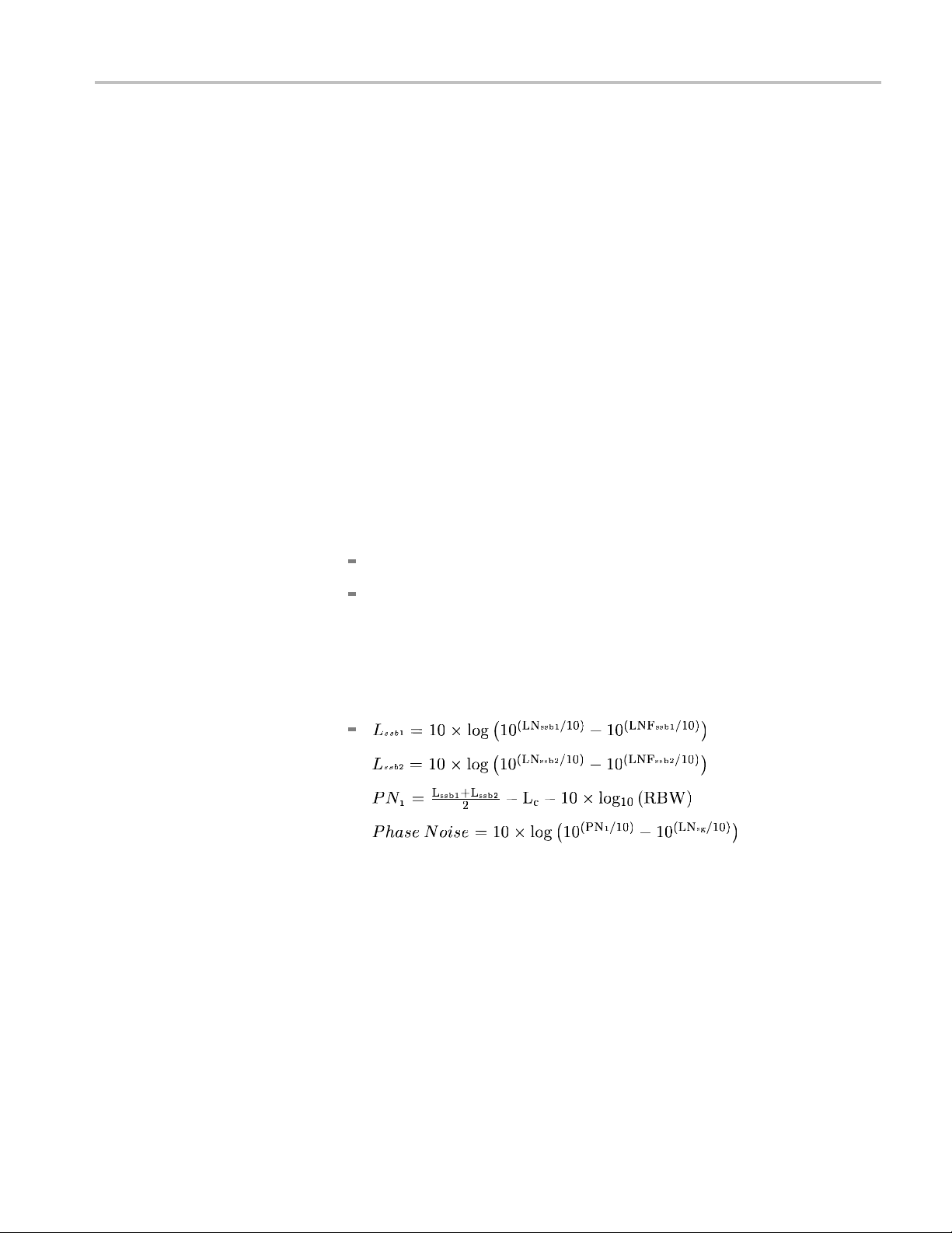
Check Phase Noise
This test deter
Signal Generator used in the test should have significantly less phase noise than
the H600 or SA2600 under test.
NOTE. The peak detector is used to measure narrowband signals such as the
CW signal from the signal source and the average detector is used to measure
wideband signals such as noise floor.
Signal Generator setup.
1. Reset the signal generator.
2. Set the frequency to 100 MHz (center frequency).
3. Set the output power level to +10 dBm.
4. Connect the RF cable from the signal generator output to the H600 or SA2600
under test RF INPUT connector.
H600/SA2600 setup.
1. Disconnect the cable from the H600/SA2600 FREQ REF connector if present.
2. Select Tools > Factory Reset
mines the phase noise of the H600 or SA2600 under test. The
3. Tap Reset All.
Phase noise verification.
Do the following steps from the H600/SA2600:
1. Tap the Spectrum drawer.
2. Tap t he More buttonintheSpectrumdrawer.
3. Tap t he Freq/Span tab and set Span to 100.000 kHz and Center Freq to
100.000 MHz.
4. Tap th e Tr ace tab and set the following:
Type to Aver age
Number of Averages to 20 (default)
Detector to +Peak
5. Tap the AutoLevel button.
6. Tap the Meas Freq marker readout box (just above the Windows CE Start
button) to set the red measurement triangle as the selected (ac tive) marker.
The application also updates the Marker-To button in the Spectrum drawer
to show the red measurement triangle icon, indicating that the Marker-To
button will act on the Meas Freq marker.
H600 & SA2600 Service Manual 1–17
Page 36

Performance Verification
7. Tap the down arr
ow button next to the Marker-To button and select Marker
to max peak. ThentapthedownarrowbuttonnexttotheMarker-Tobutton
again and select Marker to center freq to move the peak of the test signal
to the center of the display.
8. Verify that the Span is still 100 kHz and the Meas Freq marker box and center
frequency readouts are both 100 MHz.
9. Write down the level of the signal as shown in the Meas Freq marker readout
box; this is the carrier level value L
.
c
10. Tap the Tr ace tab and set the following:
Type to Aver age
Number of
Aver age s to 100
Detector to Avg ( VRM S)
11. Write down the center frequency.
12. Tap the M1 marker readout box on the bottom of the screen to open the M1
input control.
13. Tap the keypad icon in the M1 control and enter the center frequency
minus 10 kHz (offset). For example, a minus 10 kHz offset for 100 MHz
is 99.990 MHz.
14. Tap the M2 marker readout box on the bottom of the screen to open the M2
input control.
15. Tap the keypad icon in the M2 control and enter the center frequency
plus 10 kHz (offset). For example, a plus 10 kHz offset for 100 MHz is
0.010 MHz.
10
16. Determine the total sideband noise level:
a. Tap t he Reset display-control button (the X button located along the right
side of the waveform plot) to reset the measurement, then wait until the
nstrument averages the 100 measurements.
i
b. Write down the M1 marker value; this is the lower sideband noise level
LN
.
ssb1
c. Write down the M2 marker value; this is the upper sideband noise level
LN
ssb2
.
1–18 H600 & SA2600 Service Manual
Page 37
Performance Verification
17. Determine the n
oise floor levels:
a. Turn off the signal generator.
b. Tap the Reset display-control button (the X button located along the right
side of the waveform plot) to reset the measurement, then wait until the
instrument
averages the 100 measurements.
c. Write down the M1 marker value; this is the lower sideband noise floor
LNF
ssb1
.
d. Write down the M2 marker value; this is the upper sideband noise floor
ssb2
.
LNF
18. Obtain the signal generator phase noise level at 10 kHz offset for 100 MHz
N
output (L
). This may be the typical phase noise performance stated in the
sg
signal generator user manual or specification sheet, or it may be the actua l
measured phase noise data for the signal generator. The signal generator’s
guaranteed specification limit should not be usedsincethatmayleadtoan
underestimate of the H600 or SA2600 phase noise.
For the Agilent signal generator shown in the Required Equipment list, use the
following values for the signal generator phase noise level LN
:
sg
100 MHz: -143 dBc
3to6GHz: -113dBc
19. Write down the Resolution Bandwidth displayed in the Spectrum drawer
below RBW, in Hz. Use this RBW value, and values obtained earlier in this
procedure, to calculate the phase noise by using the following formulas:
[in dBc/Hz]
[in dBc/Hz]
20. Verify that the phase noise is less t han -95 dBc/Hz.
21. Repeat Phase Noise Verification steps 1 through 20, readjusting the signal
generator for all center frequencies noted in the Test Record.
H600 & SA2600 Service Manual 1–19
Page 38

Performance Verification
Check GPS function
This test deter
NOTE. The GPS antenna should be placed so that it has an unobstructed view of
the sky. If the antenna is inside a building, it may not be able to locate any GPS
signals due to signal attenuation caused by the building.
1. Reset the H600 or SA2600 application:
a. Select Tools > Factory Reset.
b. Tap Reset A
2. Connect the GPS antenna to the GPS connector on the instrument and position
the anten
a. Tap the GPS button on the main screen.
b. Roll down the menu and select Tek Internal GPS from the GPS Receiver
c. Wait until five or more green bars show in the Satellite Signal Strength
d. Check that the GPS Lock icon turns green.
mines if the H600 or SA2600 built-in GPS functions properly.
ll.
na so that it has a clear view of the sky.
drop-down list.
window.
e. Check that the Satellites in Use status field readout is ≥ 5.
1–20 H600 & SA2600 Service Manual
Page 39

Performance Verification
Check Displayed Average
Noise Level (DANL)
This test check
bandwidth).
NOTE. The DANL measurement is a measure of average noise and does not
include spurious signals. If the marker is placed on a spurious signal, it should be
moved slightly to the left or right to avoid the spurious signal.
1. Reset the H600 or SA2600 application:
a. Select Tools > Factory Reset.
b. Tap Reset All.
2. Connect a 50 Ω RF terminator to the H600 or SA2600 under test RF INPUT
connector. Disconnect the external reference.
a. Tap t he Freq button and enter 1000 MHz.
b. Set the SPAN to 10 kHz.
c. Set the
d. Tap t he Spectrum drawer.
e. Ta p t he More button.
s the H600 or SA2600 DANL with 10 Hz RBW (resolution
Ref Level to -60 dBm.
f. Tap the Trace tab.
g. Change the detector to Av era ge mode.
h. Select Average from the Trac e 1 typ e: drop-down men.
i. Tap
j. Place a marker near the center frequency and read the marker dBm value.
3. Change the Freq to 3200 MHz, 5000 MHz and 6199 MHz and repeat step j.
the x button to close the tabs.
the marker is on a spurious signal, the marker should be moved slightly
If
to the left or right to avoid the spurious signal. Record this value in the
test record.
H600 & SA2600 Service Manual 1–21
Page 40

Performance Verification
Check Residual Spurs
This test check
manual test, it is simplified to look for gross defects instead of a more rigorous
check.
1. Reset the H600 or SA2600 application:
a. Select To o l
b. Tap Reset All.
2. Connect a 50 Ohm RF terminator to the H600 or SA2600 under test RF
INPUT connector. Disconnect the external reference.
a. Tap the Spectrum drawer.
b. Tap the More button.
c. Ta p the Trace tab.
d. Change Type to Avera ge.
e. Change
f. Tap the Ampl tab.
g. Set the Ref Level to -60 dBm.
h. Tap the Freq/Span tab.
s for residual spur signals with the preamp on. Because this is a
s > Factory Reset.
the detector to Av era ge mode.
i. Set the Start frequency to 10 MHz.
j. Set the Stop frequency to 6200 MHz.
k. Set
3. Note any single frequencies that extend more than about 5 dB above the
ad
a. For any single frequencies found, adjust the span and center frequency to
b. If this single frequency exceeds the residual spur high limit of the test
c. Repeat steps a and b for any other suspect frequencies.
End of performance verification procedures.
the RBW to 100 KHz.
jacent noise floor.
duce the span to 20 MHz centered around the suspect frequency.
re
ecord, write the frequency and amplitude of this spur in the test record.
r
1–22 H600 & SA2600 Service Manual
Page 41

Theory of Operation
Page 42

Page 43

Theory of Operation
This section of the manual describes the theory of operation for the instrument
platform. As the instrument module is not user-serviceable, there is no theory
of operation
Platform
for the module.
Refer to th
e following figure while reading this section.
Display
H600 & SA2600 Service Manual 2–1
The color display is a TFT type transflective with backlight. The display inverter
mplemented on the Processor board. The color display has the following
is i
characteristics:
.4 inch diagonal size, 640 x 480 resolution, 256-color display
10
Transflective backing for indoor and outdoor viewability
Power consumption: logic 1.98 W, backlight: 5.76 W (dual cold cathode
fluorescent lamps)
Page 44

Theory of Operation
Touch Screen
LCD Controls
Processor System
The 8-wire, 10.
to the graphical user interface. It functionally replaces a mouse for Windows
navigation, substituting point and click with a touch. The touch screen has an
anti-reflective coating that reduces glare when the platform is used outdoors.
Backlighting is used for indoor viewing, and a combination of backlighting and
ambient light is used for outdoor viewing. To control brightness, use the soft keys
available on the Control Panel (Start > Settings > Control Panel > Backlight),
or double tap the backlight icon (lower-right corner of display).
Backlighting is continuously adjustable, with the default level set to 66%. The
backlight is extinguished during screen saver, suspend, and power down modes.
The instrument processor architecture is similar to that of a handheld PC with the
following exceptions:
640 x 480 TFT color display
8-wire touch screen
SPI bu
SMBus battery interface that supports two rechargeable battery packs
4 in, resistive touch-screen module provides a touch-based access
s
Expanded power management system
USB slave/host ports
Dual PCMCIA ports standard
PS/2 keyboard port
ash file system ROM for optional software and system backup
Fl
Automatic Windows CE registry restoration during cold boot up
Instrument module power management system and additional power supplies
Foreign language support
Network support
Processor Bus. The PXA255 processor external bus width is 32 bits and operates
at 100 MHz.
Temperature Sensor. The Processor board has an internal temperature sensor to
monitor the temperature of the platform.
Real-time Clock. The Processor board real-time clock operates from a separate
Lithium coin cell battery. The battery life expectancy is 7 years.
2–2 H600 & SA2600 Service Manual
Page 45

Theory of Operation
Built-in Drive
Windows CE drivers for all ports. You can reinstall these drivers by reloading
the operating system.
Flash ROM. The Processor board has the following flash ROM:
32 MB Flash ROM for the operating system and built-in drivers
32 MB Flash ROM for the nonvolatile file system memory (\BuiltInDisk)
SDRAM. The Processor board has 64 MB of DRAM. The Windows CE Control
panel provides SDRAM allocation of program and data storage memory (Start
> Setting
NOTE. When entering the Suspend state, registry information is automatically
backeduptotheflash ROM file system from SDRAM. During the suspend state,
the SDRAM retains its contents. After approximately 2 hours, the analyzer
powers down the SDRAM and enters the Shutdown (power down) state. User
application data is lost when entering the shutdown state unless previously stored
in nonv
Firmware Upgrade. You can upgrade platform firmware over the RS-232 and
USB p
rs. The Processor board is configured with vendor supplied
s > Control Panel > System > Memory).
olatile memory.
orts,aswellasbyusingaPCMCIAflashmemorycard.
Hardware and Software Configuration Data. To check the hardware and software
configurations of the platform, do the following:
1. Select Start > Programs > Tektronix Utilities > System Configuration.
2. Open the Software or Hardware tab.
lect the item of interest from the list and then select Properties.
3. Se
Electronic Keying. The platform supports electronic keying from the instrument
modules to maintain the registry. The registry is updated at each power up.
Registry information includes module name, module type, module description,
and HW/SW/FW version numbers and location. If the platform detects
configuration incompatibilities, the user is notified.
Firmware Backup. The platform backs up the the system registry to flash memory
during the power down process.
H600 & SA2600 Service Manual 2–3
Page 46

Theory of Operation
External I/O Ports and
Buses
All external po
rts are protected against electrostatic discharge and their power
supplies against shorts.
Table 2-1: External ports and buses
External por
bus Description
RS-232 port EIA/TIA-574 compliant DTE interface with modem control
USB slave, host ports Standard USB slave and host ports that support USB 1.1
Ethernet port
PCMCIA ports Supports a single type III or dual type II PCMCIA cards. Any
Keyboar
DC supp
Headphone jack A 3.5 mm jack. Inserting a headphone disables the internal
Microphone jack
t, signal, or
d port
ly jack
lines. The Baud Rate is 115.2 kbps.
standard.
Standard R
100BaseT Ethernet standards.
application software must be H600 & SA2600 platform and
Windows
5 V PC cards.
Supports PS/2 keyboards with Mini DIN connectors.
Keyboards can be plugged in without shutting down the
platfo
Accept
operation or to charge the internal batteries. Nominal supply
voltage is 24 VDC "10% .
speaker and microphone in the platform.
A 3.5 mm jack. 1.5 V bias supply, for 2 kΩ electret-type
micr
J-45 connector that supports 10BaseT and
CE compatible. This port accepts both 3.3 V and
rm.
s power from the AC power adapter for normal
ophone.
Internal I/O Ports and
Buses
internal ports are used to interface with the instrument module, display
The
modules, and development ports.
Table 2-2: Internal ports and buses
Internal port, s ig nal, or
bus Description
Color LCD Port Interface: 3.3 V, 9-bit data (8 bits used), Red, Green, and Blue
LCD Connector: 15 pin
Backlight Connector: 4 pin
Touch screen port
SMBus port Interfaces to two SMART Li-Ion battery packs. Compatible
Supports 8-wire, resistive, touch-screen panel with firmware
calibration
Touch-Screen connector: 8 pin
with Smart battery Interfaces from Inspired Energy and
others. This bus is not available to the instrument module.
(See page 2-6, Power System.) (See page 4-24, Lithium-Ion
Battery Maintenance.)
2–4 H600 & SA2600 Service Manual
Page 47

Table 2-2: Internal ports and buses (cont.)
Internal port, s ig nal, or
bus Description
Speaker port
Application interface port
Interrupt signals
Audio input signal
Audio output signal
-3 dB bandwidth: 100 Hz to 15 kHz
Speaker: 28 mm diameter, 8 W, 1 W nominal, water resistant
Connector: 2-pin header
Connects to the internal speaker. Outputs platform and
instrument module generated audio. A volume control is
available on the Control Panel (Start > Settings > Volum e &
Sounds).
Logic Levels: 3.3 V signals, 5 V tolerant
Connector: 80-pin blind mate, Molex type
SPI bus signal lines: SPIMISO (master-in-slave-out),
SPIMOSI (master-out-slave-in), SPICLK<6... 1> (SPI clock),
and SPISEL<6... 1> (instrument module select, active low).
The Application Interface port is a full duplex Serial Peripheral
Interface (SPI) bus interface between the platform and the
instrument module.
SPIMISO and SPIMOSI signals are tied together. SPISEL
and SPICLK signals are unique for a module. The platform
signals are always master; all other signals are slave.
The platform addresses the module with a unique SPISEL
signal. The instrument module picks up its SPISEL signal
from the lowest numbered SPISEL pin of the interface
connector on its front case.
The instrument modules use MODINTR<4... 1> signals for
requesting service from the platform. These signals are
open collector 3.3 V, active low, TTL-level. The instrument
module generates the MODINTR1 signal on the Processor
board. All m odule interrupt signals are OR-logic wired to form
one interrupt to the CPU. The CPU can then decode which
module a sserted the interrupt. Pull-up resistors for these
signals are located on the Processor board.
Signals: AUDIP, AUDIN
Level: 1 Vrms, maximum
Load: 10 kW
Bandwidth: -3 dB, 100 Hz to 15 kHz
A differential analog audio output signals from the instrument
module input to the platform volume control.
Signals: AUDOP, AUDON
Level: 1 Vrms, maximum
Load: 40 kW per module, 10 kW minimum impedance
Bandwidth: -3 dB, 100 Hz to 15 kHz
A differential analog output signal from the platform built-in
microphone to the input of an instrument modules.
Theory of Operation
H600 & SA2600 Service Manual 2–5
Page 48

Theory of Operation
Table 2-2: Internal ports and buses (cont.)
Internal port, s ig nal, or
bus Description
Power bus
System clock 5 MHz, 3.3 V, TTL-level (SYSCLK) for use by the instrument
Timer signal 3.3 V, TTL-level, implemented in hardware only.
Supplies power and controls the shut down of individual
instrument modules to conserve battery power.
MODON<4... 1>: 3.3 V CMOS-level s ignals. An active high
turns on the corresponding instrument module. The module
is MODON1. Only one CMOS load per line is allowed. A low
level on this signal isolates all supplies from the instrument
module. The signal must be active before addressing a
module.
module.
Programmable from 25 ms to 500 ms in 25 ms intervals.
This signal can be used to synchronously accumulate
measurement results to derive time correlated data.
Power System
The power system consists of an internal ba ttery charger and power supplies for
the internal boards and instrument module. The Processor board implements
all power management operations. The battery board controls battery charging,
battery selection, and the V
r Management. The platform processor system, peripheral devices, and I/O
Powe
main
value.
implement power management techniques similar to those used in hand-held
HPCs. This includes powering down I/O ports, power supplies, and peripherals
to a shutdown state while running the CPU in sleep mode; power to all circuits
except the real-time clock and the power system micro-controller is turned off.
The power management strategy also inc ludes a screen-saver mode. In this
ate, power to the LCD logic and backlight are shut down while maintaining
st
operation of the I/Os.
he platform uses a non-latching type power switch on the front-panel to
T
implement power on/off and suspend/resume operations similar to an HPC.
Unlike the HPC however, the platform manages power to the instrument module.
The platform shuts down power to the instrument module by pulling their
respective MODON control signals low and then cutting the power. During power
on from the suspend or shutdown state, the instrument module power supplies are
turned on first and then the module is turned on using the MODON signals.
2–6 H600 & SA2600 Service Manual
Page 49

Theory of Operation
The power modes
are:
Suspend mode. The platform automatically enters shutdown mode to save
battery power
following a period of instrument inactivity, or when you press
the front panel power button. You can set the length of this inactivity from the
Start > Settings > Control Panel > Power Management > Power Saver
tab. Before entering this mode, registry information and nonvolatile memory
are backed up and all nonessential power supplies shut down. LCD backlights
are turned off and the touch-screen display is inactivated. The instrument
module wil
l also be shut down.
During suspend mode, the real-time clock and SDRAM refresh remain active.
To return
from this state, you must press the front-panel power switch to
power up the platform, which takes approximately one minute.
Display
Power Saver mode . The front-panel status indicator changes from
Green to Amber to indicate the display Power Saver mode. In this state, the
display and backlight are turned off to save power. Instrument modules
remain powered on. Pressing the front-panel power switch cancels the Power
Saver mode and returns the platform to an active state. Measurements that are
running when you enter this mode continue to run.
Automatic Shutdown mode. If a voltage is present on fine-pitched
component pins under humid conditions, corrosion can occur over time.
ing the internal circuitry in shutdown mode when not in use can minimize
Plac
this problem. If the platform remains in shutdown mode for more than two
hours, the processor system, with the exception of the real-time clock, is
completely powered off.
Transition to the power-down state occurs when the shutdown state timer
times-out or the internal batteries becomes critically low. Pressing the
front-panel power switch reactivates the internal circuitry and returns the
platform to an active s tate.
Internal Supplies to Module. In addition to the power requirements of the internal
circuit boards, the platform provides the following voltages to the instrument
module.
Table 2-3: P latform voltage supplies to module
Characteristic Description
Voltages
Instrument Power Supply
Noise (peak-to-peak) for
1 Megahertz bandwidth
+3.4 V DC ±0.14 V, 5 A at 17 W
–13 V DC ±0.5 V, 1 A at 13 W
+13VDC±0.5V,1Aat13W
< 250 mV for ±13 V
< 100 mV for +3.4 V
1
H600 & SA2600 Service Manual 2–7
Page 50

Theory of Operation
Table 2-3: Platform voltage supplies to module (cont.)
Characteristic Description
Transient Response
Supply Monitoring The built-in diagnostics verify the instrument module power
1
The 3.4 V s
to account for the voltage drops across the connectors and Power FET switch used to control power to the
instrument module.
upply may also be referred to as the 3.3 V supply in the rest of this document. 3.4 V is specified
For 50% to 75% step load, the initial transients are ≤10% of
the initial voltage set point. Recovery is ≤2% of the set value
within 0.5 ms.
supply status while running power diagnostics. If a problem
is detected, the platform displays an out-of-tolerance warning
message.
Power Sources. The p latform and module can operate from the following
supplies:
Batteries. Powers the instrument using up to two Inspired Energy type
NI2020HD24 10.8 V, 7200 mAH, Li-ion batteries.
External Supply (DC or AC): Powers the instrument from a 24 VDC ±10%
external source. If the external supply is connected while the platform is
ting, the internal batteries will be disconnected without interrupting
opera
service. If the externa l supply is disconnected during service, the internal
batteries are connected without disrupting service.
Fuse Protection is provided by an automatic resetting fuse device. This fuse is
located in the external DC supply line on the Battery board. Requires no user
intervention.
Internal Charger. The sequential internal charger will charge a single 7200 mAH
ttery in approximately 4.5 hrs (two batteries requires approximately 9 hrs) if the
ba
platform is in shutdown mode. If the platform is operating, charging takes place
at a reduced rate in order to maintain internal temperatures within limits and to
avoid exceeding the capacity of the external supply. The charger is capable of
determining the battery technology type and appropriate charging sequence, and
is optimized for battery packs with nominal terminal voltages of between 7.2 and
12 volts. The maximum charging current is approximately 1.8 A in shutdown
mode and 0.8 A in the power on mode.
If the Desktop Power Supply or In-Vehicle Power Adapter is connected, the
internal batteries will charge if their capacity is low.
Charge Status Indicator. Low Battery Warning: Red indicates a low battery (less
than 20% remaining capacity). Green indicates battery charging. The platform
backs up current data and executes an orderly shutdown before complete loss
of battery power.
2–8 H600 & SA2600 Service Manual
Page 51

Theory of Operation
Each Li-Ion bat
level. To check the battery status, remove the battery from the analyzer. Then
press the PUSH button on the side of the battery and note the charge value on the
LED charge indicator.
Taskbar Power Status Icon. A battery icon appears in the taskbar when the
instrument
in 10% increments. If two batteries are installed, the icon displays the average
charge level of the two combined batteries. When the instrument operates from
AC power (from the Desktop Power Supply) a plug icon appears in the Taskbar
status area.
Battery S
10.8 V, 7200 mAH, Li-ion batteries. You do not need special tools to replace the
batteries. (See page 4-24, Lithium-Ion Battery Maintenance.)
Battery operation characteristics include:
The bat
watts load) from two Li-Ion batteries and approximately 4.5 hrs from a single
battery. Run time for the platform plus application varies depending on the
applications being run.
Only one of two batteries will be in use at any given time when two batteries
are installed.
tery pack has an internal microprocessor that monitors its charge
operates from battery power. The icon displays the battery charge level
ystem. The instrument uses up to two Inspired Energy type NI2020HD24
tery power system operates the platform for approximately 9 hrs (12
Measurement Module
If two batteries are installed, you can remove and replace either battery
without disrupting service.
If a second battery is installed, the platform automatically switches operation
to the second battery when the first battery reaches cut off capacity (5%
reserve) or is removed. The transition is transparent and does not interrupt
service.
Battery Power Management Utility. The Batteries tab in the Power Management
dialog box provides general information on battery status. This is the most accurate
information to determine battery charge status and probable manufacture dates.
(See page 4-26, H600 and SA2600 Instrument-Specific Battery Maintenance.)
The Measurement module contains no user-servicable parts. There are also no user
adjustments on the Measurement module. The entire instrument must be returned
for service. Service for the measurement module is not independently a vailable.
H600 & SA2600 Service Manual 2–9
Page 52

Theory of Operation
2–10 H600 & SA2600 Service Manual
Page 53

Adjustment Procedures
Page 54

Page 55

Adjustment Procedures
There are no manual or software adjustment procedures for the H600 RFHawk or
SA2600 Spectrum Analyzer instruments.
H600 & SA2600 Service Manual 3–1
Page 56

Adjustment Procedures
3–2 H600 & SA2600 Service Manual
Page 57

Maintenance
Page 58

Page 59

Cleaning
To clean the instrument, close or cover all instrument connectors, c onnector doors,
and battery doors. Then use a soft cloth dampened with a solution of water and
mild deterge
display touch screen.
CAUTION. To prevent damage to external surfaces, avoid using chemicals that
contain benzene, toluene, xylene, acetone, or similar solvents. Do not use bleach
or ammonia solutions for cleaning.
To prevent damage to internal components, do not allow moisture to get into
the instrument.
nt to clean the instrument. Do not apply heavy pressure or scrub the
H600 & SA2600 Service Manual 4–1
Page 60

Removal and Replacement Procedures
Removal and Replacement Procedures
This subsection contains procedures for the removal and replacement of all
replaceable mechanical and electrical modules.
Preparation
NOTE. The in
strument does not require calibration after removal and replacement
of the indicated parts.
WARNING.
Before doing this or any other procedure in this manual, read the
Safety Summary found at the beginning of this manual. Also, to prevent possible
damage to the instrument components, read Preventing ESD in this section. (See
page 4-3.)
This subsection contains the following items:
This preparatory information that you need to properly do the procedures
that follow.
List of tools required to remove and disassemble all modules.
dures for removal and reinstallation of the electrical and mechanical
Proce
modules.
CAUTION. Disconnect the power adapter and remove all batteries from the
instrument before disassembling the instrument.
Equipment Required
Table 4-1: Tools required
Item
no. Name Description General Tool number
1.
2. T-9 Torx tip
3. T-10 Torx tip
4. T-15 Torx tip
5.
Screwdriver handle
P0 Pozi tip
Accepts Torx-driver and
Pozi bits
Used for removing
instrument screws
Used for removing
instrument screws
Used for removing
instrument screws
Used for removing
instrument screws
620-440
640-234
640-235
640-247
640-234
4–2 H600 & SA2600 Service Manual
Page 61

Table 4-1: Tools required (cont.)
Item
no. Name Description General Tool number
6.
7.
1/4 inch nut driver
Torque driver Accepts Torx tips, Pozi
Preventing Electrostatic Damage
Electrostatic discharge (ESD) can damage components in the instrument. To
prevent, ESD:
Do not touch exposed components or connector pins unless you are using
ESD protective measures, such as wearing a properly grounded antistatic
wrist strap.
Handle boards and modules little as possible.
Removal and Replacement Procedures
Used to remove
standoffs
tips, and open-end
wrenches
Standard tool
Standard tool
Removal Procedures
Do not slide boards or modules across work surfaces.
port and store boards and modules in a static-protected bag or container.
Trans
NOTE. U nle ss directed otherwise, installation is the reverse of the removal
procedure. Note cable routing when disassembling so that you can route the
cables correctly during assembly.
NOTE. The instrument does not require calibration after removal and replacement
of the indicated parts.
H600 & SA2600 Service Manual 4–3
Page 62

Removal and Replacement Procedures
Remove Module F
Platform
rom
1. Remove the four 1/4” standoff posts.
When reinstalling these standoffs, torque them to 8 in/lb.
2. Remove the cosmetic cover.
3. Remove the four 1/4” standoff posts that secure the module to the mainframe
chassis.
When reinstalling these standoffs, torque them to 12 in/lb.
4. Remove the module from the platform.
CAUTION. Do not open the module. There are no user-serviceable parts. If
the module is opened, you must return the entire instrument to Tektronix for
calibration.
4–4 H600 & SA2600 Service Manual
Page 63

Removal and Replacement Procedures
Remove Platfor
m Rear
Cover
1. Remove th
When reinstalling these screws, torque them to 8 in/lb.
2. Remove the five screws from the bottom, side, and top edge of the rear case.
When reinstalling these screws, torque them to 8 in/lb.
e three screws from the side of the rea r case above the battery area.
3. Remove the four screws from the battery compartment area.
When reinstalling these screws, torque them to 8 in/lb.
4. Lift c
ase one to two inches and remove the carrying strap and strap pins. Also
remove the strap pins from the other corners of the case.
H600 & SA2600 Service Manual 4–5
Page 64

Removal and Replacement Procedures
Separate Front
and Rea r
Cases
Separa
Disconnect J110 and J240.
te the front and back instrument cases enough to access connecting cables.
4–6 H600 & SA2600 Service Manual
Page 65
Removal and Replacement Procedures
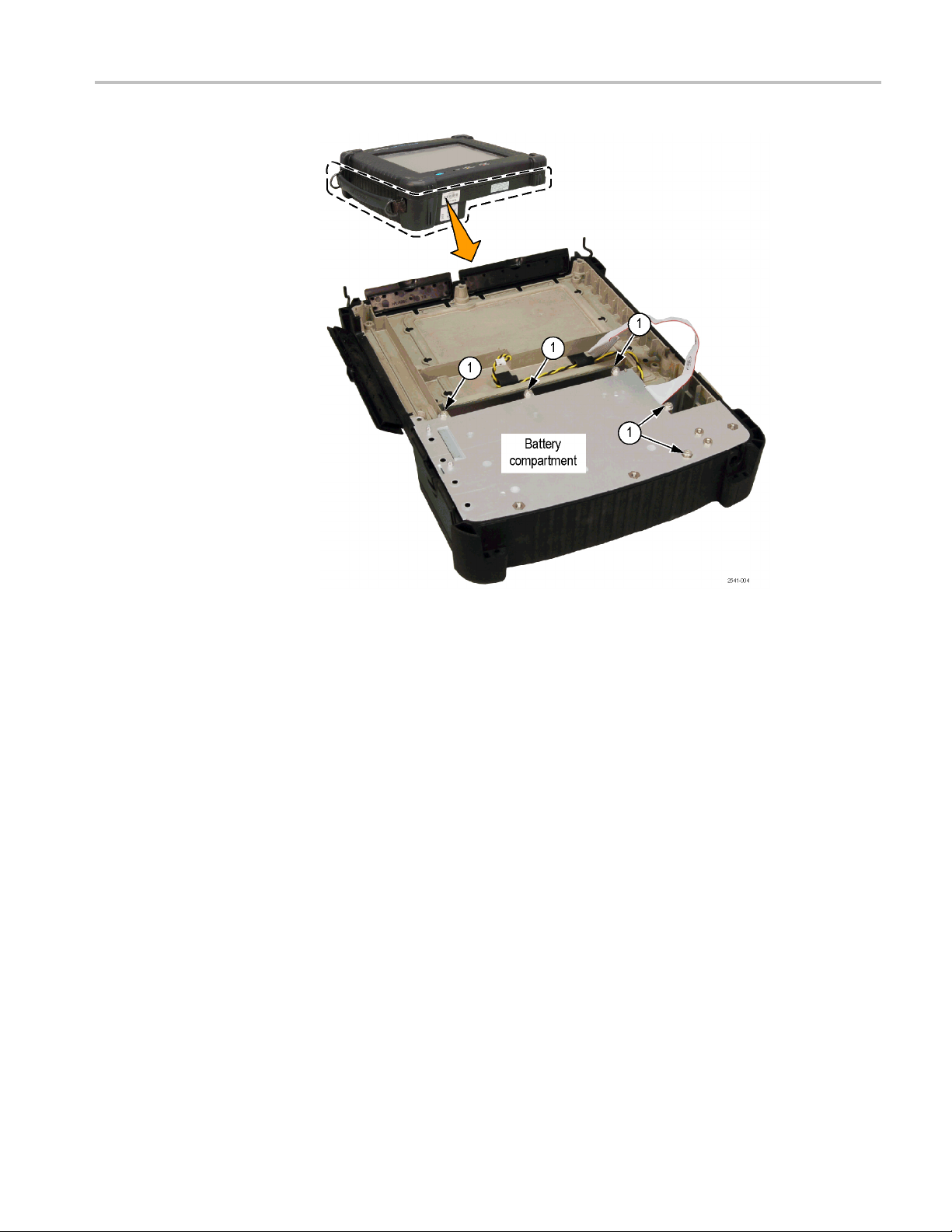
Rear Case: Remo
ve
Battery Compartment
H600 & SA2600 Service Manual 4–7
Page 66

Removal and Replacement Procedures
1. Remove the five s
the battery compartment towards the bottom of the instrument to access
connecting cables
When reinstalling these screws, torque them to 8 in/lb.
crews from the battery compartment. Lift and pivot
2. Remove the two screws and remove the battery connector board from the
battery panel c hassis. Disconnect the cable that comes from the DC power
jack.
When reinstalling these screws, torque them to 8 in/lb.
CAUTION. Do not remove the angle bracket with the foam thermal pad from the
ttery panel chassis, as it is set to a specific position.
ba
3. Remove the two scre ws and remove the battery retainer hinge assembly.
When reinstalling these screws, torque them to 8 in/lb.
4. Remove the two screws and remove the speaker bracket.
4–8 H600 & SA2600 Service Manual
Page 67

Removal and Replacement Procedures
Front Case: Remove CPU
Board Assembly
When reinstall
5. Remove the two screws and remove the DC power jack and bracket.
When reinstalling these screws, torque them to 8 in/lb.
ing these screws, torque them to 8 in/lb.
1. Disconnect JR1, J2, J120,andJ660. Disconnect the cables from the left
end of the backlight inverter board.
2. RemovetheninescrewsandremovetheCPUboardassembly.
n reinstalling these screws, torque them to 8 in/lb.
Whe
H600 & SA2600 Service Manual 4–9
Page 68
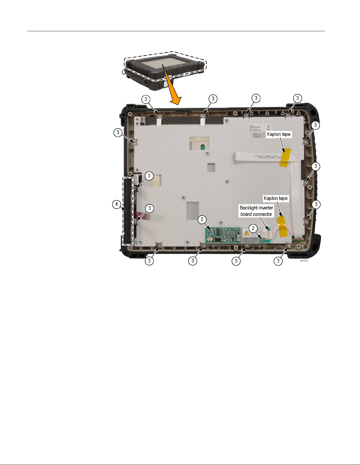
Removal and Replacement Procedures
Front Case: Rem
ove
Display Components and
Power Switch
1. Disco
2. Remo
3. Remove the 14 screws from the display assembly.
4. Remove the drive bay cover bracket from the front case. This is a pressure-fit
4–10 H600 & SA2600 Service Manual
nnect the cable from the right end of the backlight inverter board.
Untape the cable from the plate.
ve the 2 screws from the backlight inverter board and remove the board.
When reinstalling these screws, torque them to 2.5 in/lb.
When reinstalling these screws, torque them to 8 in/lb.
bracket.
Page 69
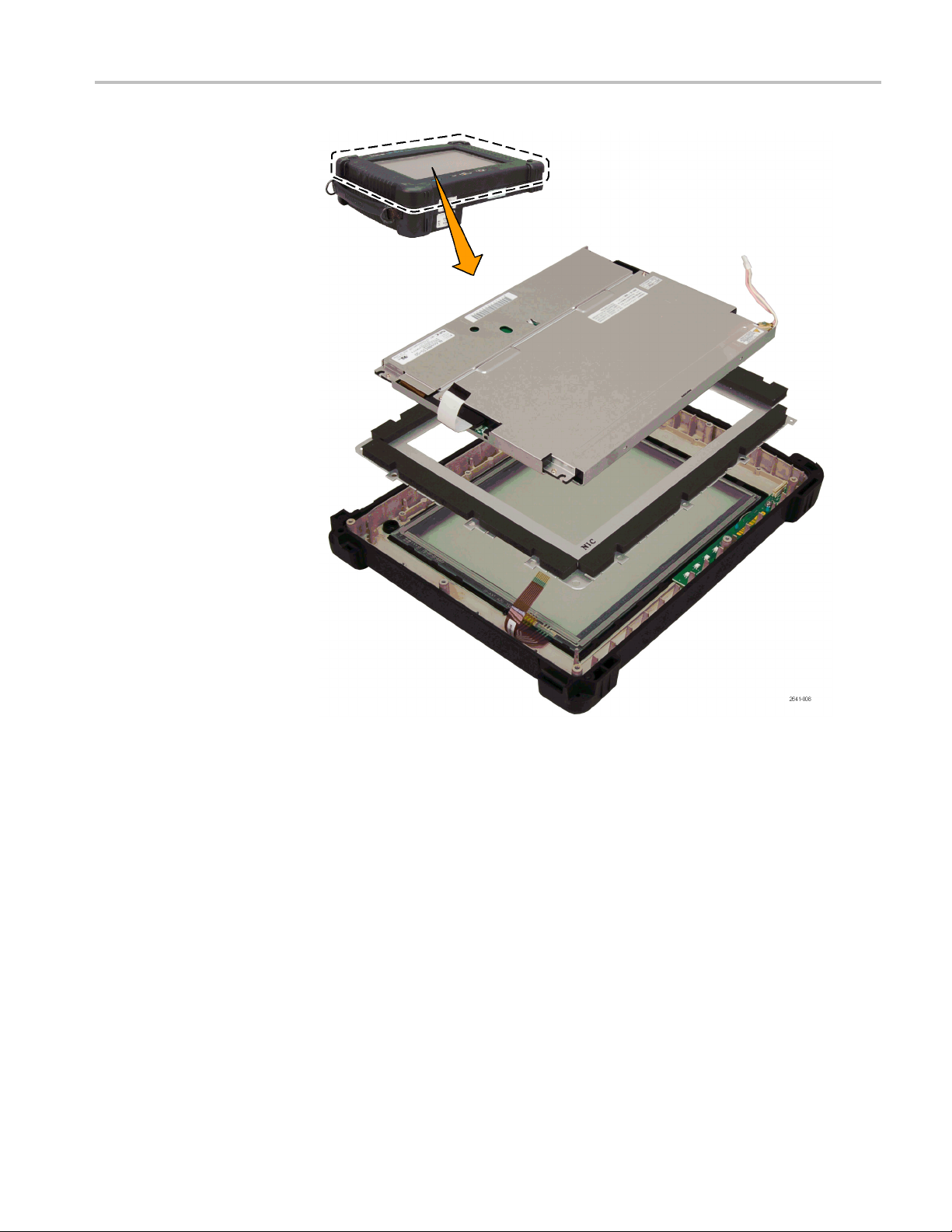
Removal and Replacement Procedures
H600 & SA2600 Service Manual 4–11
Page 70

Removal and Replacement Procedures
Front Case: Remove the
Touch Panel and Power
Switch Board
5. Lift the displa
y assembly components from the front case.
1. Remove the two screws and remove the front panel board assembly.
When reinstalling these screws, torque them to 4 in/lb.
2. Remove the touch panel assembly.
4–12 H600 & SA2600 Service Manual
Page 71
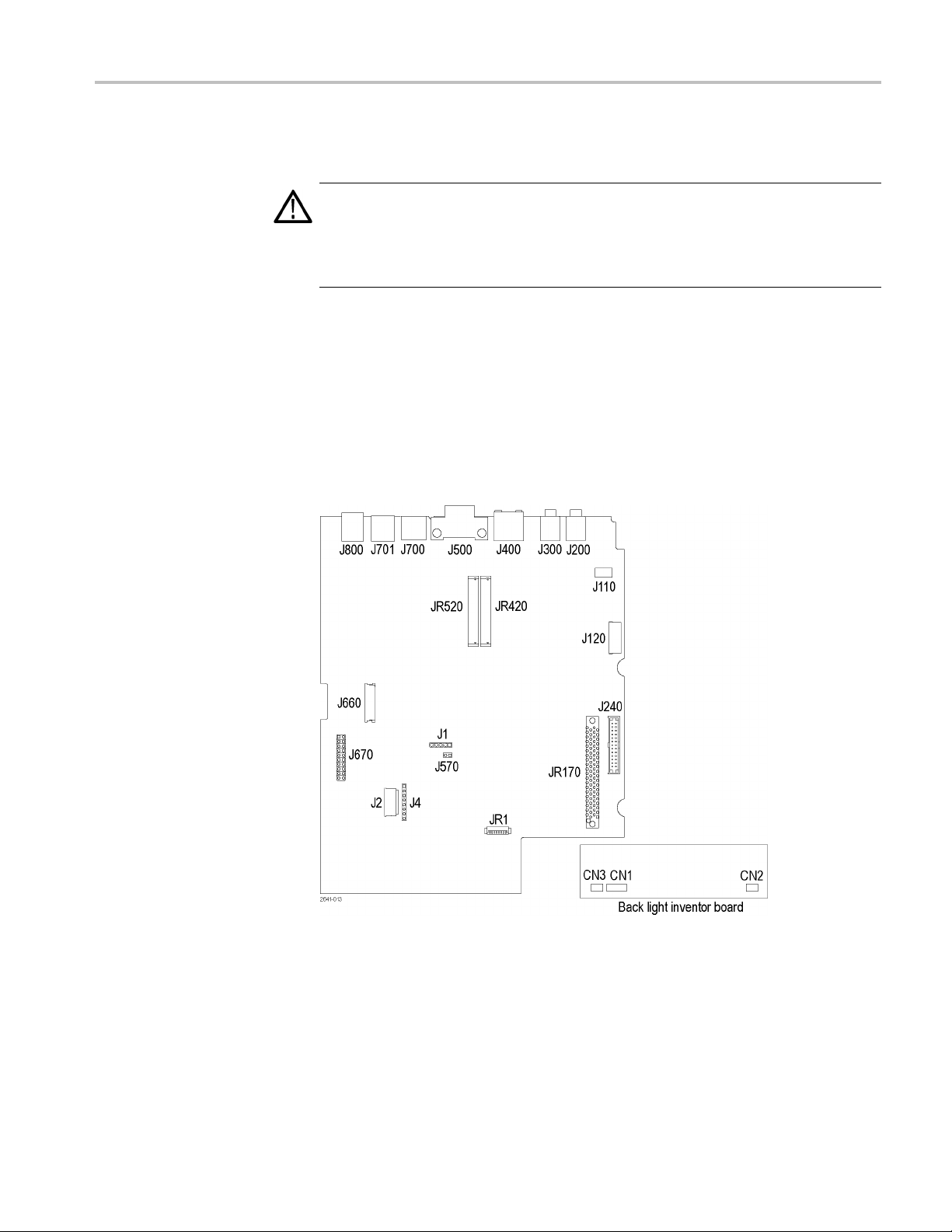
Troubleshooting
Troubleshooting
WAR NI NG . Before doing this or any other procedure in this manual, read
theSafetySu
possible injury to service personnel or damage to the instrument components,
read Installation in the product user manual, available on the Web at
www.tektronix.com, and Preventing ESD in this document.(See page 4-3.)
This section contains information and procedures designed to help you isolate
faulty modules in the H600 RFHawk or SA2600 Spectrum Analyzer.
This section assumes that service personnel have the prerequisite skills required to
work on this instrument. Details of instrument operation are not in this manual.
The following diagram shows the processor and backlight inverter board
connections. U se this diagram while doing the troubleshooting steps in this
section.
mmary found at the beginning of this manual. Also, to prevent
Figure 4-1: Processor and backlight inverter board input and output connections
H600 & SA2600 Service Manual 4–13
Page 72

Troubleshooting
Power On Self T
Display
Does Not Operate
Display Cable
Disconnected
est
Press the large oval button in the lower-left corner to power on the platform.
The power status indicator illuminates immediately. Allow several seconds for
the self test
to complete.
NOTE. The Batteries indicator briefly illuminates red if the batteries are too low to
power on the analyzer. Connect the external power supply or charge the batteries.
If the platform does not begin to boot at power up (no power up sound), try
removing the CMOS battery backup from the Processor board (BT520). Wait
approximately 15 seconds and reinsert the battery into its socket; then press the
power switch again. If the platform still does not boot, replace the Processor board.
If the display does not operate try the following procedures.
Do the following:
1. Verify that both ends of the LCD display cable are properly oriented and
fully seated in their connectors.
Backlight Does Not
Illuminate
2. Remove and reinstall the backlight cable connectors.
ese steps d o not resolve the problem, replace the display.
If th
Verify the following backlight-related voltages.
RNING. To avoid electrical shock or burn, do not touch the backlight
WA
connectors on the backlight inverter board.
able 4-2: Backlight-related voltages
T
oard
B
location Pin Location
acklight
B
Inverter board
CPU board
,3
2
1, 2 JR 1
6JR1
3, 4 J660
CN2
easured
M
voltage Frequency
10 Vrms
5
+12 VDC
0 V to +2.4 VDC
3.3 VDC
4kHz
5
4–14 H600 & SA2600 Service Manual
Page 73

Troubleshooting
Display Image
Inverted (Rotated 180°)
Disconnect and then reconnect the LCD c able connectors. To open connector
J660, insert your thumbnail beneath the dark brown part (hinge) and the cable.
Carefully li
ft up the hinged brown part to release the cable. Reseat the cable and
close the hinge. J660 pin 1 must supply +3.3 VDC for correct display orientation.
Touch Screen Does Not Operate
Try the following:
Disconnect and then reconnect the touch screen cable connectors.
J4 pins 1-8: verify that pins 1, 2, 3, and 4 of connector J1 are at +3 VDC
when the touch panel is not pressed. Verify that pins 1 through 8 toggle their
value when the touch panel is pressed.
If these do not resolve the problem, replace the touch screen panel.
Signal and Connector Information
The following tables list pin, signal name, and signal information for the main
platform connectors.
Table 4-3: PCMCIA interface connectors JR420, JR520
Signal
Pin Signal name
1
2D3 36
3D4 37D11
4D5 38D12
5
6D7 40D14
7
8 A10 42
9
10 A11 44
11 A9 45
12 A8 46 A17
13 A13 47 A18
14 A14 48 A19
15 -WE 49 A20
16
GND
D6 39 D13
-CEL
-OE
-IREQ/READY
information Pin Signal name
35
41 D15
43
50 A21
GND
-CD1
-CEH
REF/-VSI
-IORD
-IOWR
Signal
information
H600 & SA2600 Service Manual 4–15
Page 74

Troubleshooting
Table 4-3: PCMCIA interface connectors JR420, JR520 (cont.)
Signal
Pin Signal name
17
18 VPP
19 A16 53 A22
20 A15 54 A23
21 A12
22 A7 56 A25
23 A6
24 A5 58
25 A4 59 -WAIT
26 A3 60
27 A2 61
28 A1 62
29 A0 63
30 D0 64 D8
31 D1 65 D9
32 D2 66 D10
33
34
VCC 0.4 VDC
-IOIS16/WP
GND
information Pin Signal name
0.4 VDC
51
52 VPP
55
57
67
68
VCC 0.4 VDC
A24
RSVD/-VS2
-RESET
-INPACK
-REG
SPKR/BVD2
-STSCHG/BVD1
-CD2
GND
Signal
information
0.4 VDC
able 4-4: Application module connector JR170
T
Signal
Pin
1 -13 V 41 -13 V
2-13V 42
3 +3.4 V 43
4 +3.4 V 44
5
6
7
8
9
10
11
12
13
14
name
NC1
GND
SYSCLK
GND
RSVD
RSVD
GND
AUDIOUT-
AUDIOUT+
GND
Signal
information Pin
45
46 +3.4 V
+5 V high 47 +3.4 V
48
49 +13 V
50 +13 V
51
52 +13. V
53 +13. V
54
Signal
name
GND
RSVD
RSVD
GND
GND
GND
GND
Signal
information
4–16 H600 & SA2600 Service Manual
Page 75

Table 4-4: Application module connector JR170 (cont.)
Troubleshooting
Signal
Pin
15
16
17
18
19
20
21
22
23
24
25
26
27
28
29 TIMER 500 mV,
30 +3.4 V 70
31 +3.4 V 71
32
33 +3.4 V 73
34 +3.4 V 74
35
36 +3.4 V 76
37 +3.4 V
38
39
40
name
MODON6 GND
MODON5 GND
MODON4
MODON3
MODON2
MODON1
-RESET
SPISEL6
SPISEL5
SPISEL4
SPISEL3
SPISEL2
SPISEL1
NC2
STST
TXTRIG
RXTRIG
GND
EXTRIG
Signal
information Pin
55
56
57
58
59
60
61
+5 V High 62
+5 V High 63
+5 V High 64
+5 V High 65
+5 V High 66
+5 V High 67
68
69
2.5 μs/
300 ns
pulse
72
75
77
78
79
80
Signal
name
AUDIOIN-
AUDIOIN+
GND
-MODIRQ6
-MODIRQ5
-MODIRQ4
-MODIRQ3
-MODIRQ2
-MODIRQ1
GND
SPICLK6 GND
GND
SPICLK5 GND
GND
SPICLK4
GND
SPICLK3
GND
SPICLK2
GND
SPICLK1
GND
SPIRXD
GND
SPITXD
GND
Signal
information
+5 V high
+5 V high
+5 V high
+5 V high
+5 V high
+5 V high
+5 V high
+5 V high
+5 V high
+5 V high
+5 V high
+5 V high
Table 4-5: Internal speaker connector J110
Pin Signal n ame Signal information
1
2
VO1 2.4 VDC nominal
VO2 2.4 VDC
H600 & SA2600 Service Manual 4–17
Page 76

Troubleshooting
Table 4-6: Exte
Pin Signal name Signal information
1
2TIP
3
4
5
6
7
rnal microphone connector J200
GND
MICPWR
NC
NC
NC
NC
Table 4-7: Power connector J240
Pin Signal name Signal information
1
2
3
4
5
6
7
8
9
10
11
12
13
14
15 LED4_RED
16
17
18
19
20
21
22
23
24
25
26
GND
DC IN 7 - 24 VDC
DC IN 7 - 24 VDC
DC IN 7 - 24 VDC
DC IN 7 - 24 VDC
DC IN 7 - 24 VDC
GND
GND
GND
VCC_EN
GND
RESUME*
BB_PWR_SW
GND
LED4_GRN Charge LED
GND
HOST_PWR
PIC_INT*
GND
SYS_PWR_DET 3.3 VDC
GND
GNDBB_SCL Serial clock
GND
BB_SDA Serial data
GND
Enables V regulators
Power button
Digital
Charge LED
Digital
Digital
4–18 H600 & SA2600 Service Manual
Page 77

Troubleshooting
Table 4-8: Fron
Pin Signal n ame Signal information
1+3.3V
2 -LED1_RED
3
4 -LED2_RED
5
6 -LED3_RED
7
8 -LED4_R
9
10
11
12
t-panel switch/LED connector J120
-LED1_GRN 3.3 to 1.3 VDC (on/off)
-LED2_GRN 3.3 to 1.3 VDC (on/off)
-LED3_GRN 3.3 to 1.3 VDC (on/off)
ED
-LED4_GRN 3.3 to 1.3 VDC (on/off)
-RESUME 5 VDC (normal position)
-RESET 3.3 VDC (normal position)
GND
3.3 VDC
3.3 to 1.3 VDC (on/off)
3.3 to 1.3 VDC (on/off)
3.3 to +.3 VDC (on/off)
3.3 to 1.3 VDC (on/off)
Table 4-9: Serial port connector J500
Pin Signal n ame Signal information
1
2-RXD
3-TXD
4DTR
5
6
7
8
9RI
DCD
GND
DSR
RTS
CTS
Table 4-10: JTAG port connector J670
Pin Signal name Pin Signal name
1+3.3V11
2 +3.3 V 12
3
4
5
6
7
8
9
10
ICE_TRST*
GND
PX_TDI 15
GND
PX_TMS
GND
PX_TCK
GND
13
14
16
17
18
19
20
GND
GND
PX_TDO
GND
ICE_SRST*
GND
N.C.
GND
N.C.
GND
H600 & SA2600 Service Manual 4–19
Page 78

Troubleshooting
Table 4-11: PS/
Pin Signal name Signal information
1DATA
2
3
4+5V
5
6
2 keyboard connector J700
NC
GND
CLK
NC
Table 4-12: Headphone connector J300
Pin Signal name
1
2
3
4
5
6
7
GND
SPKR
SPRR
HS
-HS
NC
NC
Table 4-13: TFT color display connector J660
Pin Signal name Signal information
1
2
3
4
5
6
7
8
9 RED-3 +3 V data, mostly high
10 RED-4 +3 V data, mostly high
11 RED-5 +3 V data, mostly high
12
13
14
15
16
17
18
GND
DOT CLK
HSYNC
VSYNC
GND
GND
GND
GND
GND
GND
GND
GND
GRN-3
GRN-4
GRN-5
+3 V, 4.8 MHz
1 ms pulse, +3 V over 38 μs
1 ms pulse every 8 ms
+3 V data
+3 V data
+3 V data
4–20 H600 & SA2600 Service Manual
Page 79

Troubleshooting
Table 4-13: TFT color display connector J660 (cont.)
Pin Signal n ame Signal information
19
20
21
22
23 BLU-3 +3 V data
24 BLU-4 +3 V data
25 BLU-5 +3 V data
26
27 DEPV
28
29
30
31
GND
GND
GND
GND
GND
LCD_3V
LCD_3V
NC
RVRSE
+3.3 V
Table 4-14: TFT backlight connector CN2 (Backlight Inverter Board)
Pin Signal n ame Signal information
1
2
3
GND
AC-HV1
AC-HV2
510 V
510 V
,54kHz
rms
,54kHz
rms
Table 4-15: Touch screen connector J4 and J2
J4 Pin J2 Pin Signal name Signal information
1
28
3
46
5
63
7
81
5
XEXCITEL Excite left
XSENSEL Sense left
7
4
XSENSER Sense right
XEXCITER
YEXCITEB
Excite right
Excite bottom
YSENSEB Sense bottom
2
YSENSET Sense top
YEXCITET
Excite top
Table 4-16: Ethernet connector J400
Pin Signal n ame Signal information
1 TX+ Transmit +
2 TX- Transmit -
3RX+Receive
H600 & SA2600 Service Manual 4–21
Page 80

Troubleshooting
Table 4-16: Ethernet connector J400 (cont.)
Pin Signal name Signal information
4
5
6RX-Receive
7
8
9
10
11
12
13
14 3.3V
15
16 3.3V
NC
NC
NC
NC
GND Ground
GND Ground
NC
NC
LINKLED*
LANLED*
LED cathode
LED anode (resistor)
LED cathode
LED anode (resisitor)
Table 4-17: USB 1.1 series A host connector J701
Pin Signal name Signal information
1
2
3
4
5
6
USB_CONNECTED VBUS
USB_HDN
USB_HDP
GNDS Signal ground
CGND Case ground
CGND Case ground
DATA-
DATA+
Table 4-18: USB 1.1 series B slave connector J800
Pin Signal name Signal information
1
2
3
4
5
6
USB_HPWR VBUS
USB_N
USB_P
GNDS Signal ground
CGND Case ground
CGND Case ground
DATA-
DATA+
Table 4-19: Backlight connector JR1
Pin Signal name Signal information
1 +12BL +12 V supply
2 +12BL +12 V supply
4–22 H600 & SA2600 Service Manual
Page 81

Troubleshooting
Table 4-19: Backlight connector JR1 (cont.)
Pin Signal n ame Signal information
3
4
5
6
7
8
GND Ground
GND Ground
+5V Not used
BL_CTRL
GND
NC
Intensity control
Not used
Not used
H600 & SA2600 Service Manual 4–23
Page 82

Lithium-Ion Battery Maintenance
Lithium-Ion B attery Maintenance
Lithium-Ion rechargeable batteries require routine maintenance and care in their
use and handling. Read and follow the informationinthisdocumenttosafelyuse
Lithium-Ion
batteries and achieve the maximum battery life span.
Key Information
Battery Maintenance
Use only Tektronix-approved batteries in your Tektronix products.
Do not leave batteries unused for extended periods of time, either in the product
or in storage. When a battery has not been used for six months, check the charge
status and charge or dispose of the battery as appropriate.
The typical estimated life of a Lithium-Ion battery is about two to three years or
300 to 500 charge cycles, whichever occurs first. Onechargecycleisaperiod
of use fr
two to three year life expectancy for batteries that do not run through complete
charge cycles.
Rechargeable Lithium-Ion batteries have a limited life and will gradually lose
their capacity to hold a charge. This loss of capacity (aging) is irreversible. As
the battery loses capacity, the length of time it will power the product (run time)
decreases.
Lithium-Ion batteries continue to slowly discharge (self-discharge) when not in
use or while in storage. Routinely check the battery’s charge status. The product
user manual typically includes information on how to check battery status, as
wel
www.tektronix.com/manuals.
om fully charged, to fully discharged, and fully recharged again. Use a
l as battery charging instructions. The latest product manuals are available at
Observe and note the run time that a new fully-charged battery provides for
wering your product. Use this new battery run time as a basis to compare
po
run times for older batteries. The run time of your battery will vary depending
on the product’s configuration and the applications that you run.
Routinely check the battery’s charge status.
Carefully monitor batteries that are approaching the end of their estimated life.
Consider replacing the battery with a new one if you note either of the
following conditions:
The battery run time drops below about 80% of the original run time.
The battery charge time increases significantly.
4–24 H600 & SA2600 Service Manual
Page 83
Lithium-Ion Battery Maintenance
Charging
Storage
Always follow t
your product’s user manual and/or online help for detailed information about
charging its battery. The latest version of your Tektronix product user manual is
available at www.tektronix.com.
NOTE. When you troubleshoot battery is sues for dual battery configurations,
test one battery and one battery slot at a time. A defective battery can prevent
the battery
batteries.
Charge or discharge the b attery to approximately 50% of capacity before
storage.
Remove the battery and store it separately from the product.
Store the battery at temperatures between 5 °C and 20 °C (41 °F and 68 °F).
Charge the battery to approximately 50% of capacity at least once every six
months.
NOTE. The battery self-discharges during storage. Higher temperatures (above
20 °C or 68 °F) reduce the battery storage life.
he charging instructions provided with your product. R efer to
in the opposite slot from charging, leaving you with two uncharged
Handling Precautions
CAUTION. If a battery is stored or otherwise unused for an extended period
without following these instructions, and the battery has no charge remaining
when you check it, consider it to be damaged. Do not attempt to recharge it or to
it. Replace it with a new battery.
use
Do not disassemble, open, crush, bend, deform, puncture, or shred a battery.
Do not drop a battery or expose the battery to excessive shock or vibration.
Do not short circuit a battery or allow metallic or conductive objects to contact
the battery terminals.
Do not dispose of a battery in fire or water.
Do not use the battery to power any devices other than the instrument for
which it was designed.
Keep the battery away from personnel that are not trained to use the
instrument.
Do not expose a battery to temperatures above 60 °C (140 °F).
H600 & SA2600 Service Manual 4–25
Page 84
Lithium-Ion Battery Maintenance
Transportation
Disposal and Recycling
Keep the batter
Do not use a damaged battery.
If a battery pack is leaking fluids, do not touch any fluids. Properly dispose of
a leaking battery pack (see Disposal and Recycling in this document).
WARNING. In
flush eyes thoroughly with water for at least 15 minutes, lifting upper and lower
lids, until no evidence of the fluid remains. Seek medical attention.
Always check all applicable local, national, and international regulations
before transporting a Lithium-Ion battery.
Transporting an end-of-life, damaged, or recalled battery may, in certain
cases, be specifically limited or prohibited.
Lithium-Ion batteries are subject to disposal and recycling regulations that
vary by country and region. Always check and follow your applicable
regulations before disposing of any battery. Contact Rechargeable Battery
Recycling Corporation (www.rbrc.org) for U.S.A. and Canada, or your local
battery recycling organization.
y away from children.
case of eye contact with battery fluids, do not rub eyes. Immediately
Many countries prohibit the disposal of waste electronic equipment in
standard waste receptacles.
Place only discharged batteries in a battery collection container. Use electrical
tape or other approved covering over the battery connection points to prevent
rt circuits.
sho
H600 and SA2600 Instrument-Specific Battery Maintenance
he instrument run time depends on power consumption, which in turn depends
Instrument Run Time
T
on the instrument measurement mode. For example, DPX™ Spectrum Display,
Spectrum analyzer, and audio de modulation measurements consume more power
than other measurements because they are continuously acquiring data.
With two new, fully charged batteries, you can run the DPX Spectrum
Display measurement for approximately four hours, or the Spectrum analyzer
measurement for five to six hours. Both of these run times are with the instrument
power management mode disabled. Enabling instrument power management
increases the instrument run time.
4–26 H600 & SA2600 Service Manual
Page 85
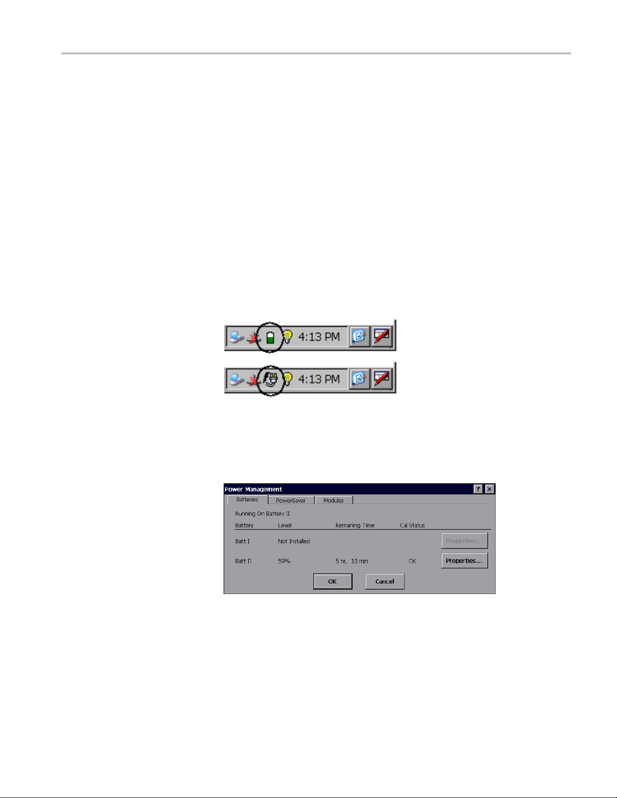
Lithium-Ion Battery Maintenance
Battery Charge Time
Checking the Battery
Charge Status
Battery aging a
battery charge capacity to decrease, which in turn decreas es the instrument run
time.
The instrument uses one battery at a time. The battery with the lowest remaining
capacity is used first.
With the ins
two batteries from a fully dis charged state. The exact charge time depends on
which measurements are running. When the instrument is powered off, it will take
about 10 hours to fully charge two batteries.
1. Double-tap the Power Management icon in the system tray to open the
Power Management dialog box. The system tray shows the battery icon
when the instrument is operating from batteries, and a power plug icon when
the instrument is operating from an external power supply.
nd the increasing number of charge/discharge cycles causes the
trument powered on, it can take more than 20 hours to fully charge
2. Tap the Batteries tab. This tab shows the charge level of each battery,
the estimated remaining run time for the in-use battery (with the current
urement settings), and the battery calibration status. The instrument
meas
uses one battery at a time: the battery with the lowest remaining capacity
is used first.
Each battery contains circuitry that monitors the charge level and estimated
remaining run time. This circuit becomes uncalibrated after a number of
partial discharge and charge cycles. When the Cal Status is Uncalibrated,
the reported level and remaining time are not accurate, which means that
H600 & SA2600 Service Manual 4–27
Page 86
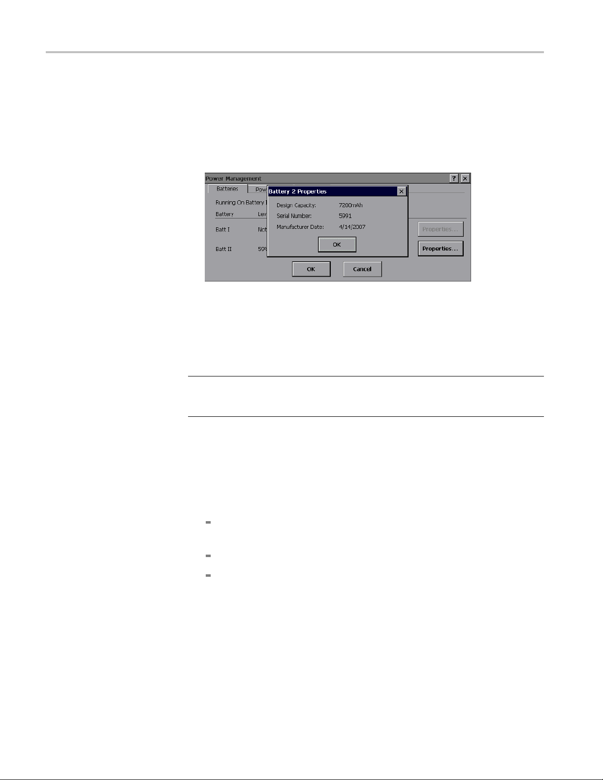
Lithium-Ion Battery Maintenance
Calibrating a Battery
the battery is n
document.
3. Tap the Proper
Design Capacity, Serial Number and the Manufacturer Date. Use the serial
number to identify and keep track of each battery’s charge and capacity
history.
To calibrate a battery, y ou must first fully charge, then fully discharge, and finally
fully charge the battery to reset the internal battery monitoring circuitry.
Fully Charging a Battery.
ot calibrated. See the Calibrating a Battery sectioninthis
ties button adjacent to a battery listing to show that battery’s
NOTE. During charging, keep the instrument environment temperature between
0°Can
80%.
1. Install the single battery that you want to charge.
2. Connect the external power adaptor, but do not power up the instrument. The
3. When the battery is fully charged, the BATTERIES CHARGER LED on the
4. Power on the instrument and double-tap the Power Management icon in
5. Verify that the Level field shows Fully Charged for the installed battery.
d 45 °C (32 °F and 113 °F), and the relative humidity between 0% and
BATTERIES CHARGER LED on the front panel should be lit, indicating that
e instrument is charging the battery. If the BATTERIES CHARGER LED
th
on the front panel is not lit, check the following:
e external power adaptor plug is fully seated in the instrument external
Th
power connector
here is power being supplied to the external power adaptor
T
The battery is fully seated in the instrument battery compartment
front panel turns off.
the system tray.
4–28 H600 & SA2600 Service Manual
Page 87

Lithium-Ion Battery Maintenance
Fully Discharg
NOTE. During battery discharge, keep the instrument environment temperature
between –10 °C and 5 0 °C (14 °F and 122 °F), and the relative humidity between
0% and 80%.
1. Disconnect the external power adaptor.
2. Install th
3. Power on the instrument and a measurement application.
4. Double-tap the Power Management icon in the system tray.
5. Tap the Power Saver tab and select No Power Saver actions.
6. Set the instrument to a high-power-consumption measurement such as DPX
Spectrum.
7. Let the instrument and measurement run. The instrument automatically shuts
down when the battery is fully discharged. The battery is now completely
discharged.
ing a Battery.
e single battery that you want to discharge.
When to Replace a Battery
Record the date, battery serial number, charge time and run time when you start
using a new instrument, or when you install new batteries. Set up a schedule to
check and record the battery charge and calibration status. See the Checking the
Battery Charge Status section in this document.
Compare the charge time and instrument run times with those for new batteries at
least every six months. When any of the following behaviors occur, you should
nsider replacing your batteries:
co
It takes significantly longer (>150%) to charge used batteries than it does to
harge new batteries.
c
The BATTERIES CHARGER LED on the front panel does not stay on
continuously while the batteries are charging.
After the battery is fully charged, the instrument run time is significantly
shorter (<80%) with older fully-charged batteries than it is with new batteries.
A charge cycle never completes.
The Power Management Batteries tab does not show a Fully Charged status
after a charge cycle.
The battery is more than three years old.
H600 & SA2600 Service Manual 4–29
Page 88

Repackaging for Shipment
Repackaging f
or Shipment
CAUTION. Remove rechargeable battery packs from the instrument before
shipping and store the batteries in an approved area. (See page 4-24, Lithium-Ion
Battery Maintenance.)
To ship the instrument for repair, use the original packaging container if possible.
If the container is unfit for use or not available, use the metal carrying case if
available, or, repackage the instrument as follows:
1. Useacartonwithateststrengthofnolessthan80kg(175lbs).
2. Surround the instrument with protective polyethylene sheeting.
3. Cushion the instrument on all sides with at least two inches of tightly packed
urethane foam or other packing material.
4. Seal the carton with shipping tape or an industrial stapler.
4–30 H600 & SA2600 Service Manual
Page 89

Replaceable Parts
Page 90

Page 91

Replaceable Parts
This section contains a list of the replaceable parts for the H600 RFHawk and the
SA2600 Spectrum Analyzer. Use this list to identify and order replacement parts.
Parts Ordering Information
Changes to Tektronix products are sometimes made to accommodate improved
components as they become available and to give you the benefit of the latest
improvements. Therefore, when ordering parts, it is important to include the
following
Using the Replaceable Parts List
information in your o rder:
Part number
Instrument type or model number
Instrument serial number
Instrument modification number, if applicable
This section contains a list of the mechanical and/or electrical components that
are replaceable for the H600 RFHawk and the SA2600 Spectrum Analyzer. Use
this list to identify and order replacement parts. The following table describes
each column in the parts list.
Column Column name Description
1
2 Part number
3 and 4
5
6 Name and description
Abbreviations
Fig. & index number Items in this section are referenced by figure and index numbers to the
exploded view illustrations that follow.
Use this part number when ordering replacement parts from Tektronix.
Serial number Column three indicates the serial number at which the part was first
effective. Column four indicates the serial number at which the part was
discontinued. No entry indicates the part is good for all serial numbers.
Qty This indicates the quantity of parts used.
An item name is separated from the description by a colon (:). Because
of space limitations, an item name may sometimes appear as incomplete.
Use the U.S. Federal Catalog handbook H6-1 for further item name
identification.
Abbreviations conform to American Abbreviations National Standard ANSI
Y1.1-1972.
H600 & SA2600 Service Manual 5–1
Page 92

Replaceable Parts
Figure 5-1: Module and cover replaceable parts
5–2 H600 & SA2600 Service Manual
Page 93

Replaceable Parts
Fig. &
Index
number
5-1
Part
number
-1 129-1650-xx 4
-2 200-5048-xx 1
-3 129-1649-xx 4
Serial
number
effective
Serial
number
discont’d Qty Description
Module and mainframe
SPACER, POST; 8-32 X .975 LG
COVER,COSMETIC; MODULE CHASSIS; SAFETY CONTROLLED
SPACER, POST; 8-32, 2.350 LG
H600 & SA2600 Service Manual 5–3
Page 94

Replaceable Parts
Figure 5-2: Mainframe replaceable parts
5–4 H600 & SA2600 Service Manual
Page 95

Replaceable Parts
Fig. &
index
number
5-2-1 202-0370-02 1
-2 211-0530-xx 3
-3 335-1928-xx 1
-4 211-0628-xx
-5
-6 211-1095-xx 4
-7
-8 407-4924-xx 1
-9 671-5609-xx 1
-10 174-4676-0x 1
-11 119-6806-xx 1
-12 211-0069-xx 2
-13 407-4926-xx 1
-14 211-0722-xx 29
-15 174-5592-xx 1
-16 119-7495-xx 1
-17 407-4994-xx 1
-18 119-6948-xx 1
-19 211-0324-xx 2
-20 671-4682-xx 1
-21 407-4923-xx 1
-22 344-0568-xx 2
-23 202-0405-xx 1
-24 334-9863-xx 1
-25 260-2716-xx 1
-26 335-1931-xx 1
-27 367-0516-xx 1
-28 174-4777-xx 1
-29 664-5633-xx 1
-30 386-7408-xx 1 PANEL,BATTERY:4.600 X 8.835,0.063 AL
-31 407-4610-xx 1
-32 119-6811-xx 1
-33 211-0722-xx
-34 407-5007-xx 1
-35 342-1127-xx 1
-36 211-0722-xx 4
-37 174-4774-xx 1
-38 407-4686-xx 1
-39 214-4951-xx 1
Tektronix
part
number
131-6867-xx 1
211-0747-xx 9
Serial
no.
effective
Serial
no.
discont’d Qty. Name & description
CASE,REAR:OVERMOLD ASSY,13.494 X 11.381 X 3.529
SCREW,MACHINE:6-32 X 1.750,PNH,STL CD PL,POZ
MARKER,IDENT:REAR PANEL SAFETY LABEL
5
7
SCREW,MACHINE:6-32 X 1.125,PNH,SST POZ
CONN,HDR:SMD,MALE,RTANG,68 POS,PCMCIA,DUAL
SCREW, MACHINE:2-56 X 0.625L, PNH, PHL, STL, ZN PL
SCREW, MACHINE; 6-32 X 0.188, PNH, STL, CDPL
BRACKET; DRIVE MODULE, 0.040 AL
CIRCUIT BD ASSY:CPU,TESTED
CABLE ASSY, BACKLIGHT INVERTER
CIRCUIT BD ASSY, BACKLIGHT INVERTER
SCREW,MACHINE; 2-56 X 0.125,PNH,STL CRM PL,POZ
BRACKET,DISPLAY COVER; AL
SCREW,MACHINE; 6-32 X 0.250,PNH,STL,CDPL,T-15 TORX
CABLE ASSEMBLY; DISPLAY
DISPLAY MODULE; LCD;640 X 480,10.4 IN DIAGONAL
BRACKET:LCD COLOR,8.5 X 10.65,0.300 AL
TOUCH SCREEN:TOUCH PANEL ASSEMBLY, 8-WIRE
SCR,ASSEM WSHR; 4-40 X 0.188,PNH,SST,PASS,T-9 TORX
CIRCUIT BD ASSY; FRONT, TESTED
BRACKET; FLOPPY BAY,BLACK ANODIZE, 0.040 AL
CLIP:ACCESSORY CASE,16 GA WIRE,BLACK OXIDE COAT
CASE,FRONT:OVER MOLD ASSY,12.786 X 9.903 X 1.2,BLACK
MARKER,IDENT:LABEL,MKD RESET,FRONT,LEXAN
SWITCH,KEYPAD:FRONT ELASTOMER MAT,PLASTIC
MARKER,IDENT:FRONT,MKD W/TEK LOGO,LEXAN
HANDLE,STRAP:HOLDING,W/VELCRO ADJUSTMENT
CA ASSY,SP:FLAT FLEX,IDC,12 CON,0.039 CTR
CKT BD SUBASSY:BATTERY CONNECTOR
BRACKET:SPEAKER,1.45 X 1.45 L,0.050 AL
SPEAKER:DYNAMIC,28MM DIA,8 OHM,600-7KHZ
SCREW,MACHINE; 6-32 X 0.250,PNH,STL,CDPL,T-15 TORX
BRACKET; ANGLE, THERMAL PAD
INSULATOR,MISC,THERMAL; BATTERY,0 .125 THICK
SCREW,MACHINE; 6-32 X 0.312,FLH100,STL,CDPL,T-10
CABLE ASSY:DISCRETE,CPD,3,22 AWG,(DC JACK)
BRACKET:DC JACK,1.175 X 1.675 X 1.130,0.050 AL
HINGE ASSEMBLY:0.024 THK,SSTL,NICKEL PLATE
H600 & SA2600 Service Manual 5–5
Page 96
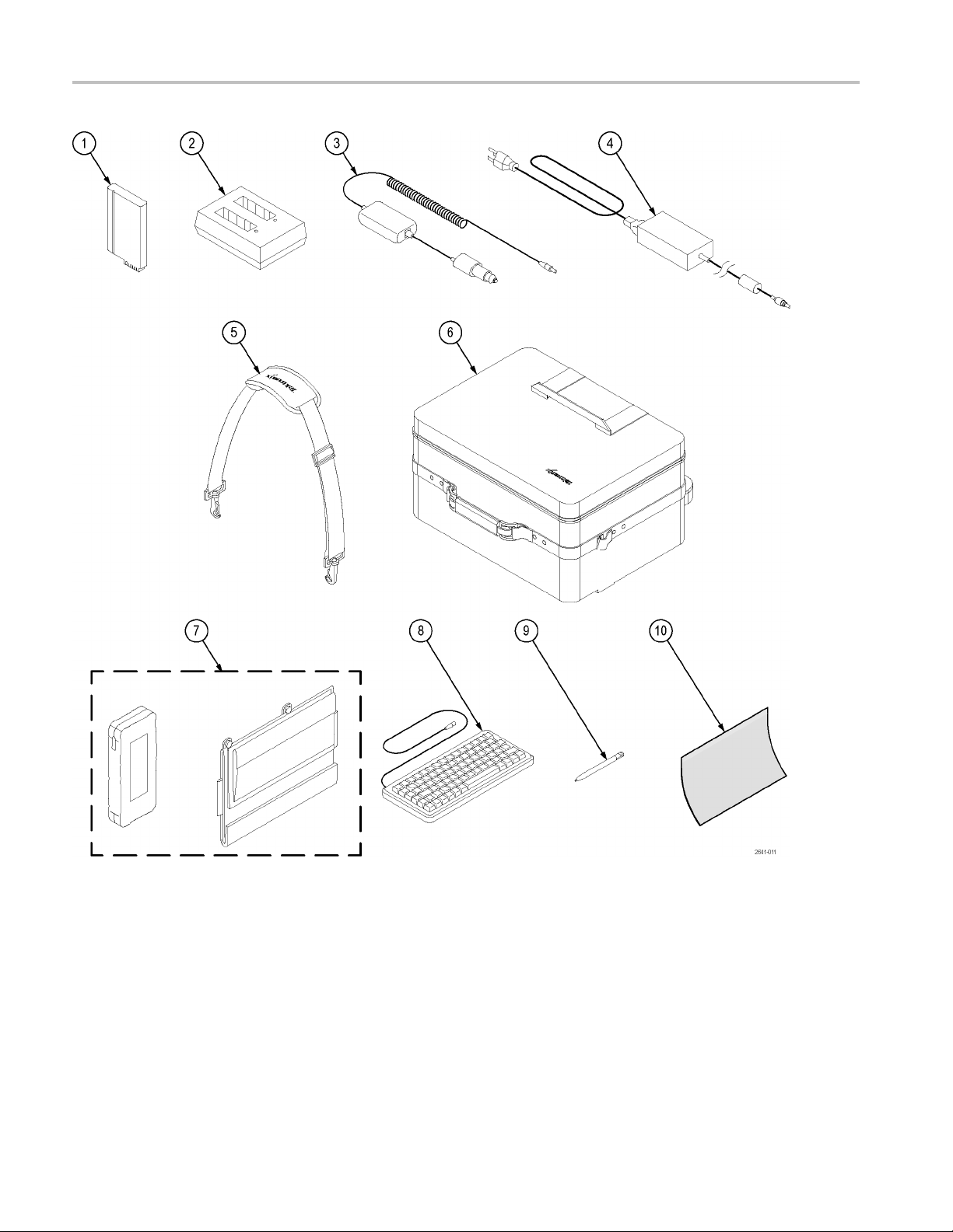
Replaceable Parts
Figure 5-3: H600 and SA2600 accessories
5–6 H600 & SA2600 Service Manual
Page 97

Replaceable Parts
Fig. &
index
number
5-3-1 146-0151-0x 1
-2 119-6030-00 1
-3 119-6028-00 1
-4 119-7288-0x 1
-5
-6 016-1775-00 1
——–
-7
-8 118-9402-00 1
-9 119-6107-00 1
-10 016-1882-00
——–
——–
——–
——–
——–
——–
——–
——–
——–
——–
——–
——–
——–
——–
——–
——–
Tektronix
part
number
367-0518-00 1
016-1889-00 1
348-1661-00 1
012-1588-00 1
012-1379-00 1
174-4401-00 1
071-2641-XX 1
116-0996-00 1
116-0997-00 1
116-0998-00 1
116-0999-00 1
161-0310-00 1
161-0311-00 1
161-0312-00 1
161-0313-00 1
161-0314-00 1
161-0315-00 1
161-0318-00 1
436-0416-00 1
Serial
no.
effective
Serial
no.
discont’d Qty. Name & description
BATTERY; LITHIUM ION, RECHARGEABLE; 10.8V, 7200MAH, SMBUS,RECESSED
TERMINALS
BATTERY CHARGER:2-SLOT EXTERNAL CHARGER, 10MA-3A SMBUS, SBS3002
ADAPTER,POWER:VEHICLE CIGARETTE LIGHTER ADAPTER,VOLTAGE
BOOSTED,60W,12VDC IN, 24VDC,2.5A OUT
POWER SUPPLY; EXTERNAL;65W, 90-264 VAC, 47-63HZ IN; 24 VDC, 2.7A OUT
HANDLE,STRAP:SHOULDER,W/CLIPS
CASE,CARRYING:TRANSPORTATION SOFT SHELL
CASE,CARRYING:HAND,POLYETHYLENE,24L X 16W X 13H EXTERIOR,17L X 13W X
9H INTERIOR,FOAM DICE CUT LAYER PADS
STAND,TILT:ACRYLIC/ALUMINUM COVERED W/CORDURA,W/ACCESSORY POUCH
KEYBOARD ASSY:83 KEY NOTEBOOK KEYBOARD, IBM AT OR PS/2
COMPATIBLE,GRAY
STYLUS:STYLUS FOR TOUCH SCREEN,T1100
5
COVER:PROTECTIVE,TOUCH PANEL,3M POLYTHYLENE TAPE,CLEAR
CABLE,ELEC:PC INTERFACE
CABLE ASSEMBLY:RS232, 76.0 L ,9, 24 AWG DB9 FEMALE X DB9 FEMALE, SERIAL
NULL MODEM
CABLE ASSY,I/O; USB, 26 AWG, 3 FT, A TO B, MALE, BLACK
MANUAL, TECH; SERVICE, H600 & SA2600
DISK DRIVE;PCMCIA;128MB, TYPE II, ATA FLASH CARD, 2.5MS ACCESS, CARD BUS
MODEM:V.90,PC CARD 56K-GLOBAL-FREEDOM,5660
ETHERNET CARD:STANDARD LP-E LOW POWER ETHERNET CARD,EA0911-101
PRINTER:HP DESKJET 340CBI PORTABLE PRINTER,PARALLEL INTERFACE,C2671A
CA ASSY,PWR:3,18 AWG,BLACK,250V/2.5A,STR,118L,RECP IEC320 C5 X NEMA
5-15P,US
CA ASSY,PWR:3,250V/2.5A,STR,IEC320 C5,EUROPEAN,BLACK
CABLE ASSY,PWR:3,1.0MM SQ,250V/2.5A,STR,RECP IEC320 C5,UNITED
KINGDOM,BLACK
CA ASSY, PWR:3,0.75MM SQ,BLACK,250V/2.5A,STR,RECP IEC320 C5, AUSTRALIAN
CA ASSY,PWR:3,0.75MM SQ,BLACK,250V/2.5A,STR, RECP IEC320 C5,SWISS
CA ASSY, PWR:3,1.25MM SQ,250V/2.5A,STR,RECP IEC320
C5,JAPANESE,T-MARK,BLACK
CABLE ASSY,PWR; 3,18 AWG,BLACK,250V,7.5A,STR,IEC320 C5,3C
CERTIFICATION,CHINA
SHELF,UTILITY; MAGNETIC,11.5 H X 15.0 W X 0.25 D,SAFETY CONTROLLED
H600 & SA2600 Service Manual 5–7
Page 98

Replaceable Parts
5–8 H600 & SA2600 Service Manual
Page 99

Specifications
Page 100

 Loading...