

Page 1

User Manual
Grass Valley Model 3000
Digital Production Switcher
Software Release 5.3
071-0159-00
Revised Printing: February, 1998
Page 2

Telephone
Numbers
North America
(800) 547-8949
Fax: (530) 478-3181
Elsewhere
Distributor or sales office
from which equipment was
purchased.
Web Addresses
Grass Valley Email
Support
GVGSERVICE@tek.com
Grass Valley W eb Page
http://www.tek.com/Grass_
Valley
Tektronix W eb Site
http://www.tek.com
Postal Addresses
Mail
Tektronix Grass Valley
Products
P.O. Box 1114
Grass Valley, CA 95945
Shipping
Tektronix Grass Valley
Products
400 Providence Mine Rd.,
Nevada City, CA 95959
Customer Support
Tektronix Grass Valley Products is committed to providing the
most responsive and professional product support available. We
have a fully staffed, highly trained support team ready to respond
to anything from a simple question to an emergency repair. Support is available via telephone or email. For new and updated customer support documents, as well as new product information,
check the Tektronix web site and Grass Valley’s web page.
Copyright © Tektronix, Inc. All rights reserved. Printed in U.S.A.
Tektronix products are covered by U.S. and foreign patents, issued and pending.
Information in this publication supersedes that in all previously published material. Specifications and price change privileges reserved. TEKTRONIX, TEK, Grass
Valley Group, Borderline, E-MEM, TEN-X, Wavelink, and are registered
trademarks, and Air Link, Auto Match, Doubletake, E-Disk, Eagle V, Emphasys,
EZ-Link, 409, Grass Valley, Horizon, Jogger, Kadenza, Kaleidoscope, K-Mask,
Key-Layer, Key-Link, Krystal, MASTER System, Master 21, MAX, Omni-Key, Performer, Programmed Motion, Silhouette, Softset, SqueezeBack, Streamline, Super
Edit, TEN-20, 20-TEN, Trace, TrailBlazer, VideoDesktop, Flex-Time, and XEDL are
trademarks of Tektronix, Inc. P.O. Box 1000 Wilsonville, OR 97070-1000 U.S.A.
The information in this manual is furnished for informational use only, is subject
to change without notice, and should not be construed as a commitment by Tektronix, Inc. Tektronix assumes no responsibility or liability for any errors or inaccuracies that may appear in this publication.
Tektronix, Inc., Video and Networking Division, P.O. Box 1114 Grass Valley, California 95945 U.S.A.
Page 3

Contents
Preface
Welcome to the Model 3000 . . . . . . . . . . . . . . . . . . . . . . . . . . . . . . . . . . . . . xi
Organization of This Manual . . . . . . . . . . . . . . . . . . . . . . . . . . . . . . . . xii
How to use this manual . . . . . . . . . . . . . . . . . . . . . . . . . . . . . . . . . . . . . . . . xiii
Conventions used in this manual . . . . . . . . . . . . . . . . . . . . . . . . . . . . . . . . xiv
Button and Panel Knob References . . . . . . . . . . . . . . . . . . . . . . . . . . . xiv
Menu References . . . . . . . . . . . . . . . . . . . . . . . . . . . . . . . . . . . . . . . . . . xv
Soft Button and Soft Knob References . . . . . . . . . . . . . . . . . . . . . . . . xv
Section 1 — System Overview
Introduction . . . . . . . . . . . . . . . . . . . . . . . . . . . . . . . . . . . . . . . . . . . . . . . . . . 1-1
General Description . . . . . . . . . . . . . . . . . . . . . . . . . . . . . . . . . . . . . . . . . . . 1-2
Standard Features . . . . . . . . . . . . . . . . . . . . . . . . . . . . . . . . . . . . . . . . . . . . . 1-3
Optional Features . . . . . . . . . . . . . . . . . . . . . . . . . . . . . . . . . . . . . . . . . . . . . 1-4
Physical Description . . . . . . . . . . . . . . . . . . . . . . . . . . . . . . . . . . . . . . . . . . . 1-5
Signal Processor Frame . . . . . . . . . . . . . . . . . . . . . . . . . . . . . . . . . . . . . 1-5
Power Supplies . . . . . . . . . . . . . . . . . . . . . . . . . . . . . . . . . . . . . . . . . . . 1-6
Control Panel . . . . . . . . . . . . . . . . . . . . . . . . . . . . . . . . . . . . . . . . . . . . . 1-7
Video and Key Inputs and Outputs . . . . . . . . . . . . . . . . . . . . . . . . . . . . . . 1-9
Inputs . . . . . . . . . . . . . . . . . . . . . . . . . . . . . . . . . . . . . . . . . . . . . . . . . . . 1-9
Outputs . . . . . . . . . . . . . . . . . . . . . . . . . . . . . . . . . . . . . . . . . . . . . . . . . 1-11
Functional Description . . . . . . . . . . . . . . . . . . . . . . . . . . . . . . . . . . . . . . . . 1-13
Overview . . . . . . . . . . . . . . . . . . . . . . . . . . . . . . . . . . . . . . . . . . . . . . . 1-13
Video Processing . . . . . . . . . . . . . . . . . . . . . . . . . . . . . . . . . . . . . . . . . 1-14
Description of Options . . . . . . . . . . . . . . . . . . . . . . . . . . . . . . . . . . . . . . . . 1-18
iii
Page 4

Contents
Section 2 — Startup & Configuration
Dual Chroma Keyer . . . . . . . . . . . . . . . . . . . . . . . . . . . . . . . . . . . . . . . 1-18
Borderline® Key Edge Generation . . . . . . . . . . . . . . . . . . . . . . . . . . 1-18
Secondary Wipe Generator . . . . . . . . . . . . . . . . . . . . . . . . . . . . . . . . 1-18
Safe Title/Action Area Generator . . . . . . . . . . . . . . . . . . . . . . . . . . . 1-19
Mix/Effects Clean Feed . . . . . . . . . . . . . . . . . . . . . . . . . . . . . . . . . . . 1-19
Frame Store . . . . . . . . . . . . . . . . . . . . . . . . . . . . . . . . . . . . . . . . . . . . . . 1-19
Effects Send . . . . . . . . . . . . . . . . . . . . . . . . . . . . . . . . . . . . . . . . . . . . . . 1-19
Tally Output . . . . . . . . . . . . . . . . . . . . . . . . . . . . . . . . . . . . . . . . . . . . . 1-20
Tally Expansion . . . . . . . . . . . . . . . . . . . . . . . . . . . . . . . . . . . . . . . . . . 1-20
Remote Auxiliary Bus Control Panels . . . . . . . . . . . . . . . . . . . . . . . 1-20
Chroma Key Auto Setup . . . . . . . . . . . . . . . . . . . . . . . . . . . . . . . . . . . 1-20
Introduction . . . . . . . . . . . . . . . . . . . . . . . . . . . . . . . . . . . . . . . . . . . . . . . . . . 2-1
Powering Up . . . . . . . . . . . . . . . . . . . . . . . . . . . . . . . . . . . . . . . . . . . . . . . . . 2-2
Boot-Up . . . . . . . . . . . . . . . . . . . . . . . . . . . . . . . . . . . . . . . . . . . . . . . . . . 2-2
System Status . . . . . . . . . . . . . . . . . . . . . . . . . . . . . . . . . . . . . . . . . . . . . 2-3
Software Setup . . . . . . . . . . . . . . . . . . . . . . . . . . . . . . . . . . . . . . . . . . . . . . . . 2-7
The Configuration Menu . . . . . . . . . . . . . . . . . . . . . . . . . . . . . . . . . . . 2-7
Setting System Parameters . . . . . . . . . . . . . . . . . . . . . . . . . . . . . . . . . . . . . 2-10
Setting the System Clock . . . . . . . . . . . . . . . . . . . . . . . . . . . . . . . . . . . 2-12
Configuring Inputs . . . . . . . . . . . . . . . . . . . . . . . . . . . . . . . . . . . . . . . . . . . 2-14
Setting Input Digital Resolution . . . . . . . . . . . . . . . . . . . . . . . . . . . . 2-16
Configuring External Key Sync . . . . . . . . . . . . . . . . . . . . . . . . . . . . . 2-17
Configuring Key Setup . . . . . . . . . . . . . . . . . . . . . . . . . . . . . . . . . . . . 2-18
Mapping Crosspoints . . . . . . . . . . . . . . . . . . . . . . . . . . . . . . . . . . . . . 2-19
Formatting Chroma Key Inputs . . . . . . . . . . . . . . . . . . . . . . . . . . . . . 2-22
Assigning GPI Inputs . . . . . . . . . . . . . . . . . . . . . . . . . . . . . . . . . . . . . 2-23
Configuring Outputs . . . . . . . . . . . . . . . . . . . . . . . . . . . . . . . . . . . . . . . . . 2-26
Setting Switcher Output Timing . . . . . . . . . . . . . . . . . . . . . . . . . . . . 2-28
Setting Output Digital Resolution . . . . . . . . . . . . . . . . . . . . . . . . . . . 2-30
Configuring External Interfaces . . . . . . . . . . . . . . . . . . . . . . . . . . . . . . . . 2-32
Setting Editor Port Parameters . . . . . . . . . . . . . . . . . . . . . . . . . . . . . . 2-33
Configuring a DPM . . . . . . . . . . . . . . . . . . . . . . . . . . . . . . . . . . . . . . . 2-34
Video Connection (Aux Buses and Return Inputs) . . . . . . . . . 2-34
DPM Capabilities (Fixed and Pooled) . . . . . . . . . . . . . . . . . . . . 2-35
iv
Page 5

Contents
Control Connections . . . . . . . . . . . . . . . . . . . . . . . . . . . . . . . . . . 2-40
Configuring the DPM Interface . . . . . . . . . . . . . . . . . . . . . . . . . 2-41
For Kaleidoscope . . . . . . . . . . . . . . . . . . . . . . . . . . . . . . . . . . . . . 2-42
For a DPM-700 . . . . . . . . . . . . . . . . . . . . . . . . . . . . . . . . . . . . . . . 2-42
For DVEous: . . . . . . . . . . . . . . . . . . . . . . . . . . . . . . . . . . . . . . . . . 2-43
For Other Non-Poolable DPMs . . . . . . . . . . . . . . . . . . . . . . . . . 2-43
Mapping DPM Aux Buses . . . . . . . . . . . . . . . . . . . . . . . . . . . . . . . . . 2-44
Mapping DPM Inputs . . . . . . . . . . . . . . . . . . . . . . . . . . . . . . . . . . . . . 2-45
Mapping DPM Returns . . . . . . . . . . . . . . . . . . . . . . . . . . . . . . . . . . . 2-46
Mapping Kaleidoscope Source Buttons . . . . . . . . . . . . . . . . . . . . . . 2-48
Configuring the Peripheral Interface . . . . . . . . . . . . . . . . . . . . . . . . 2-49
Assigning Peripheral Triggers . . . . . . . . . . . . . . . . . . . . . . . . . . . . . . 2-50
Configuring GPI Outputs . . . . . . . . . . . . . . . . . . . . . . . . . . . . . . . . . . 2-52
Formatting Aux Buses . . . . . . . . . . . . . . . . . . . . . . . . . . . . . . . . . . . . . . . . 2-53
Setting User Preferences . . . . . . . . . . . . . . . . . . . . . . . . . . . . . . . . . . . . . . 2-54
Setting Shift Lock Operation . . . . . . . . . . . . . . . . . . . . . . . . . . . . . . . 2-54
To Shift Lock a Bus . . . . . . . . . . . . . . . . . . . . . . . . . . . . . . . . . . . . 2-55
To Unshift Lock a Bus . . . . . . . . . . . . . . . . . . . . . . . . . . . . . . . . . 2-55
Setting Keyer Preferences . . . . . . . . . . . . . . . . . . . . . . . . . . . . . . . . . . 2-56
Setting Preview Preferences . . . . . . . . . . . . . . . . . . . . . . . . . . . . . . . . 2-58
Setting Beeper Preferences . . . . . . . . . . . . . . . . . . . . . . . . . . . . . . . . . 2-62
Setting User-Defined System Defaults . . . . . . . . . . . . . . . . . . . . . . . . . . 2-63
Operating Notes . . . . . . . . . . . . . . . . . . . . . . . . . . . . . . . . . . . . . . . . . . . . . 2-64
Field Dominance Selection . . . . . . . . . . . . . . . . . . . . . . . . . . . . . . . . . 2-64
Use of Field Dominance . . . . . . . . . . . . . . . . . . . . . . . . . . . . . . . 2-64
Using the Mask Draw Feature . . . . . . . . . . . . . . . . . . . . . . . . . . . . . . 2-65
Mask Draw Setup . . . . . . . . . . . . . . . . . . . . . . . . . . . . . . . . . . . . . 2-67
Operating the Model 3000 With a DPM-700 . . . . . . . . . . . . . . . . . . 2-68
To Enable the Model 3000 . . . . . . . . . . . . . . . . . . . . . . . . . . . . . . 2-68
Operating the Model 3000 With Kaleidoscope . . . . . . . . . . . . . . . . 2-70
To Enable the Model 3000 . . . . . . . . . . . . . . . . . . . . . . . . . . . . . . 2-70
To Enable Kaleidoscope . . . . . . . . . . . . . . . . . . . . . . . . . . . . . . . 2-70
Remote Aux Panel Joystick Override . . . . . . . . . . . . . . . . . . . . . . . . 2-71
Joystick Override Programming . . . . . . . . . . . . . . . . . . . . . . . . 2-71
v
Page 6

Contents
Section 3 — Switcher Concepts
Clear Working Buffer . . . . . . . . . . . . . . . . . . . . . . . . . . . . . . . . . . . . . . . . . . 3-2
CWB Modes of Operation . . . . . . . . . . . . . . . . . . . . . . . . . . . . . . . . . . . 3-3
Auto Delegation . . . . . . . . . . . . . . . . . . . . . . . . . . . . . . . . . . . . . . . . . . . . . . 3-4
Crosspoint Bus . . . . . . . . . . . . . . . . . . . . . . . . . . . . . . . . . . . . . . . . . . . . . . . . 3-5
Transitions . . . . . . . . . . . . . . . . . . . . . . . . . . . . . . . . . . . . . . . . . . . . . . . . . . . 3-6
Cut Transition . . . . . . . . . . . . . . . . . . . . . . . . . . . . . . . . . . . . . . . . . . . . . 3-6
Mix Transition . . . . . . . . . . . . . . . . . . . . . . . . . . . . . . . . . . . . . . . . . . . . 3-6
Wipe Transition . . . . . . . . . . . . . . . . . . . . . . . . . . . . . . . . . . . . . . . . . . . 3-8
Keys . . . . . . . . . . . . . . . . . . . . . . . . . . . . . . . . . . . . . . . . . . . . . . . . . . . . . . . . . 3-9
Luminance Key . . . . . . . . . . . . . . . . . . . . . . . . . . . . . . . . . . . . . . . . . . 3-10
Linear Key . . . . . . . . . . . . . . . . . . . . . . . . . . . . . . . . . . . . . . . . . . . . . . . 3-12
Preset Pattern Key . . . . . . . . . . . . . . . . . . . . . . . . . . . . . . . . . . . . . . . . 3-12
Shaped and Unshaped Video . . . . . . . . . . . . . . . . . . . . . . . . . . . . . . . . . . 3-13
Input Shaped and Unshaped Video . . . . . . . . . . . . . . . . . . . . . . . . . 3-14
Output Shaped and Unshaped Video . . . . . . . . . . . . . . . . . . . . . . . . 3-14
Super Black . . . . . . . . . . . . . . . . . . . . . . . . . . . . . . . . . . . . . . . . . . . . . . . . . . 3-15
Chroma Key . . . . . . . . . . . . . . . . . . . . . . . . . . . . . . . . . . . . . . . . . . . . . . . . . 3-16
Coring . . . . . . . . . . . . . . . . . . . . . . . . . . . . . . . . . . . . . . . . . . . . . . . . . . . . . . 3-18
Layering . . . . . . . . . . . . . . . . . . . . . . . . . . . . . . . . . . . . . . . . . . . . . . . . . . . . 3-19
E-MEM Effects Memory . . . . . . . . . . . . . . . . . . . . . . . . . . . . . . . . . . . . . . . 3-20
Effects and Keyframes . . . . . . . . . . . . . . . . . . . . . . . . . . . . . . . . . . . . . 3-20
Enables and Delegates . . . . . . . . . . . . . . . . . . . . . . . . . . . . . . . . . . . . . 3-21
Enables and Delegates Button Tallies . . . . . . . . . . . . . . . . . . . . 3-22
Keyframing / Timelines / Effects Editing . . . . . . . . . . . . . . . . . . . . . . . 3-23
Effects Editing Definitions . . . . . . . . . . . . . . . . . . . . . . . . . . . . . . . . . 3-24
Timeline Menu . . . . . . . . . . . . . . . . . . . . . . . . . . . . . . . . . . . . . . . . . . . 3-25
Manipulating Video Images . . . . . . . . . . . . . . . . . . . . . . . . . . . . . . . . . . . 3-26
Effects Send (Option) . . . . . . . . . . . . . . . . . . . . . . . . . . . . . . . . . . . . . . . . . 3-28
Frame Store (Option) . . . . . . . . . . . . . . . . . . . . . . . . . . . . . . . . . . . . . . . . . 3-29
vi
Page 7

Section 4 — Switcher Operations
About this Section . . . . . . . . . . . . . . . . . . . . . . . . . . . . . . . . . . . . . . . . . . . . . 4-1
Starting Conditions . . . . . . . . . . . . . . . . . . . . . . . . . . . . . . . . . . . . . . . . . . . . 4-2
Switcher Hardware Setup . . . . . . . . . . . . . . . . . . . . . . . . . . . . . . . . . . 4-2
Clearing the Switcher . . . . . . . . . . . . . . . . . . . . . . . . . . . . . . . . . . . . . . 4-4
Transitions - Mix/Effects Bus Operations . . . . . . . . . . . . . . . . . . . . . . . . 4-6
Background Cut . . . . . . . . . . . . . . . . . . . . . . . . . . . . . . . . . . . . . . . . . . . 4-6
Background Mix . . . . . . . . . . . . . . . . . . . . . . . . . . . . . . . . . . . . . . . . . . 4-9
Wipe Operations . . . . . . . . . . . . . . . . . . . . . . . . . . . . . . . . . . . . . . . . . . . . . 4-11
Background Wipe . . . . . . . . . . . . . . . . . . . . . . . . . . . . . . . . . . . . . . . . 4-11
Pattern Mixing . . . . . . . . . . . . . . . . . . . . . . . . . . . . . . . . . . . . . . . 4-15
Learning User Wipes . . . . . . . . . . . . . . . . . . . . . . . . . . . . . . . . . . 4-16
Fade to Black . . . . . . . . . . . . . . . . . . . . . . . . . . . . . . . . . . . . . . . . . . . . 4-19
Setting Transition Rates . . . . . . . . . . . . . . . . . . . . . . . . . . . . . . . . . . . 4-20
Background and Matte Generator Operations . . . . . . . . . . . . . . . . 4-22
Matte Selection . . . . . . . . . . . . . . . . . . . . . . . . . . . . . . . . . . . . . . . 4-23
Super Black . . . . . . . . . . . . . . . . . . . . . . . . . . . . . . . . . . . . . . . . . . 4-23
Luminance and Linear Keying Operations . . . . . . . . . . . . . . . . . . . . . . . 4-24
Key Transition . . . . . . . . . . . . . . . . . . . . . . . . . . . . . . . . . . . . . . . . . . . 4-28
Preset Pattern Keying Operations . . . . . . . . . . . . . . . . . . . . . . . . . . . . . . 4-29
Layered Mode Operations . . . . . . . . . . . . . . . . . . . . . . . . . . . . . . . . . . . . . 4-32
Chroma Keying Operations . . . . . . . . . . . . . . . . . . . . . . . . . . . . . . . . . . . 4-33
Auto Chroma Keying Procedure . . . . . . . . . . . . . . . . . . . . . . . . . . . . 4-34
Auto Setup . . . . . . . . . . . . . . . . . . . . . . . . . . . . . . . . . . . . . . . . . . . 4-36
Basic Manual Adjustment . . . . . . . . . . . . . . . . . . . . . . . . . . . . . . 4-37
Optimization Adjustments . . . . . . . . . . . . . . . . . . . . . . . . . . . . . 4-39
E-MEM (Effects Memory) Operations . . . . . . . . . . . . . . . . . . . . . . . . . . . 4-43
New Operational Mode Available – Version 5.1 and later . . . . . . 4-44
Normal Mode . . . . . . . . . . . . . . . . . . . . . . . . . . . . . . . . . . . . . . . . 4-44
Learn A Register . . . . . . . . . . . . . . . . . . . . . . . . . . . . . . . . . . . . . . 4-45
Recall A Register . . . . . . . . . . . . . . . . . . . . . . . . . . . . . . . . . . . . . . 4-46
300 Style Mode – 3-M/E Switchers Only . . . . . . . . . . . . . . . . . . . . . 4-47
Operational Defaults in Either Mode . . . . . . . . . . . . . . . . . . . . . . . . 4-47
Setup . . . . . . . . . . . . . . . . . . . . . . . . . . . . . . . . . . . . . . . . . . . . . . . . . . . 4-48
Basic E-MEM Operations . . . . . . . . . . . . . . . . . . . . . . . . . . . . . . . . . . 4-48
Enabling E-MEM Register Levels . . . . . . . . . . . . . . . . . . . . . . . 4-48
Learn Enables . . . . . . . . . . . . . . . . . . . . . . . . . . . . . . . . . . . . . . . . 4-49
Contents
vii
Page 8

Contents
Storing an Effect . . . . . . . . . . . . . . . . . . . . . . . . . . . . . . . . . . . . . . 4-50
Recalling an Effect . . . . . . . . . . . . . . . . . . . . . . . . . . . . . . . . . . . . 4-50
Learning Effects Dissolve Transitions . . . . . . . . . . . . . . . . . . . . 4-51
E-MEM Learn Sequence Operations . . . . . . . . . . . . . . . . . . . . . 4-52
Undo Function . . . . . . . . . . . . . . . . . . . . . . . . . . . . . . . . . . . . . . . . . . . 4-53
Keyframe Operations . . . . . . . . . . . . . . . . . . . . . . . . . . . . . . . . . . . . . . . . . 4-54
Setup . . . . . . . . . . . . . . . . . . . . . . . . . . . . . . . . . . . . . . . . . . . . . . . . . . . 4-54
Basic Editing . . . . . . . . . . . . . . . . . . . . . . . . . . . . . . . . . . . . . . . . . . . . . 4-54
Learn Keyframes . . . . . . . . . . . . . . . . . . . . . . . . . . . . . . . . . . . . . . 4-55
Advanced Keyframe Editing . . . . . . . . . . . . . . . . . . . . . . . . . . . . . . . 4-56
Version 5.2 and later software changes . . . . . . . . . . . . . . . . . . . 4-58
Working With Keyframe Timelines . . . . . . . . . . . . . . . . . . . . . . 4-60
Setting and Adjusting Start Times . . . . . . . . . . . . . . . . . . . . . . . 4-61
Zoom and Pan Timeline Effects . . . . . . . . . . . . . . . . . . . . . . . . . 4-62
Cut, Copy, and Paste Keyframes . . . . . . . . . . . . . . . . . . . . . . . . 4-63
Effects Editing with Get and Put . . . . . . . . . . . . . . . . . . . . . . . . 4-65
Constant Duration Mode . . . . . . . . . . . . . . . . . . . . . . . . . . . . . . . 4-65
Using Path Types To Change An Effect . . . . . . . . . . . . . . . . . . 4-66
Effects Send Operations (Option) . . . . . . . . . . . . . . . . . . . . . . . . . . . . . . . 4-68
Setup . . . . . . . . . . . . . . . . . . . . . . . . . . . . . . . . . . . . . . . . . . . . . . . . . . . 4-68
Effects Send Looping Mode . . . . . . . . . . . . . . . . . . . . . . . . . . . . . . . . 4-70
Effects Send Non-Looping Mode . . . . . . . . . . . . . . . . . . . . . . . . . . . 4-70
Frame Store Operations (Option) . . . . . . . . . . . . . . . . . . . . . . . . . . . . . . . 4-71
Setup . . . . . . . . . . . . . . . . . . . . . . . . . . . . . . . . . . . . . . . . . . . . . . . . . . . 4-71
Output Routing . . . . . . . . . . . . . . . . . . . . . . . . . . . . . . . . . . . . . . . . . . 4-71
Still Image Storage . . . . . . . . . . . . . . . . . . . . . . . . . . . . . . . . . . . . . . . . 4-72
Building A Recursive Effect . . . . . . . . . . . . . . . . . . . . . . . . . . . . 4-72
Video and Key . . . . . . . . . . . . . . . . . . . . . . . . . . . . . . . . . . . . . . . . 4-73
Mask Store . . . . . . . . . . . . . . . . . . . . . . . . . . . . . . . . . . . . . . . . . . . 4-73
Freeze Mode . . . . . . . . . . . . . . . . . . . . . . . . . . . . . . . . . . . . . . . . . . . . . 4-74
Frame Store Field Modes . . . . . . . . . . . . . . . . . . . . . . . . . . . . . . . . . . 4-74
Field 1 / Field 2 . . . . . . . . . . . . . . . . . . . . . . . . . . . . . . . . . . . . . . . 4-74
2 Field / 4 Field . . . . . . . . . . . . . . . . . . . . . . . . . . . . . . . . . . . . . . . 4-74
Grab Mode . . . . . . . . . . . . . . . . . . . . . . . . . . . . . . . . . . . . . . . . . . . . . . 4-75
Dropshadow Mode . . . . . . . . . . . . . . . . . . . . . . . . . . . . . . . . . . . . . . . 4-75
Repositioning . . . . . . . . . . . . . . . . . . . . . . . . . . . . . . . . . . . . . . . . . . . . 4-76
Mosaics . . . . . . . . . . . . . . . . . . . . . . . . . . . . . . . . . . . . . . . . . . . . . . . . . 4-76
Pseudo Color . . . . . . . . . . . . . . . . . . . . . . . . . . . . . . . . . . . . . . . . . . . . 4-76
Filter . . . . . . . . . . . . . . . . . . . . . . . . . . . . . . . . . . . . . . . . . . . . . . . . . . . . 4-76
Crop . . . . . . . . . . . . . . . . . . . . . . . . . . . . . . . . . . . . . . . . . . . . . . . . . . . . 4-76
viii
Page 9

Floppy Disk Drive Operations . . . . . . . . . . . . . . . . . . . . . . . . . . . . . . . . . 4-77
Format Diskettes . . . . . . . . . . . . . . . . . . . . . . . . . . . . . . . . . . . . . . . . . 4-77
Creating Directories and Files . . . . . . . . . . . . . . . . . . . . . . . . . . . . . . 4-78
Store and Name An E-MEM File . . . . . . . . . . . . . . . . . . . . . . . . 4-78
Store and Name A Configuration File . . . . . . . . . . . . . . . . . . . . 4-79
Viewing (Listing) Files and Directories . . . . . . . . . . . . . . . . . . 4-82
Deleting Files and Directories . . . . . . . . . . . . . . . . . . . . . . . . . . 4-82
Appendix A — Shaped and Unshaped Video
Introduction . . . . . . . . . . . . . . . . . . . . . . . . . . . . . . . . . . . . . . . . . . . . . . . . . A-1
What are Shaped and Unshaped Video? . . . . . . . . . . . . . . . . . . . . . . . . A-1
Input Shaped and Unshaped Video . . . . . . . . . . . . . . . . . . . . . . . . . . . . . A-2
Configuring the Input . . . . . . . . . . . . . . . . . . . . . . . . . . . . . . . . . . . . . A-3
Examples of Operation With Shaped and Unshaped Fill Video . . . . . A-4
Correct Input Configuration . . . . . . . . . . . . . . . . . . . . . . . . . . . . . . . A-6
Correct Operation With Shaped Fill Video . . . . . . . . . . . . . . . A-6
Correct Operation With Unshaped Fill Video . . . . . . . . . . . . . A-8
Incorrect Input Configuration . . . . . . . . . . . . . . . . . . . . . . . . . . . . . . A-9
Incorrect Operation With Shaped Fill Video . . . . . . . . . . . . . . A-9
Incorrect Operation With Unshaped Fill Video . . . . . . . . . . . A-11
Output Shaped and Unshaped Video . . . . . . . . . . . . . . . . . . . . . . . . . . A-13
For the Model 3000: . . . . . . . . . . . . . . . . . . . . . . . . . . . . . . . . . . A-13
For the Model 4000 or Model 2200: . . . . . . . . . . . . . . . . . . . . . A-15
Installation Considerations . . . . . . . . . . . . . . . . . . . . . . . . . . . . . . . . . . . A-16
Contents
Appendix B — Keyframe Facts
Keyframe Timelines . . . . . . . . . . . . . . . . . . . . . . . . . . . . . . . . . . . . . . . . . . . B-1
Master Timeline . . . . . . . . . . . . . . . . . . . . . . . . . . . . . . . . . . . . . . . . . . . B-1
Enables and Delegates . . . . . . . . . . . . . . . . . . . . . . . . . . . . . . . . . . . . . . . . . B-3
Keyframe Path Control . . . . . . . . . . . . . . . . . . . . . . . . . . . . . . . . . . . . . . . . B-5
Tension, Continuity, and Bias Controls . . . . . . . . . . . . . . . . . . . . . . . B-5
Path Vectors . . . . . . . . . . . . . . . . . . . . . . . . . . . . . . . . . . . . . . . . . . B-6
Tension Control . . . . . . . . . . . . . . . . . . . . . . . . . . . . . . . . . . . . . . . B-7
Continuity Control . . . . . . . . . . . . . . . . . . . . . . . . . . . . . . . . . . . . B-10
Bias Control . . . . . . . . . . . . . . . . . . . . . . . . . . . . . . . . . . . . . . . . . . B-13
ix
Page 10

Contents
Appendix C — Super Black
Glossary
Index
Definition of Super Black . . . . . . . . . . . . . . . . . . . . . . . . . . . . . . . . . . . . . . C-1
Objective . . . . . . . . . . . . . . . . . . . . . . . . . . . . . . . . . . . . . . . . . . . . . . . . . . . . C-1
Limitations . . . . . . . . . . . . . . . . . . . . . . . . . . . . . . . . . . . . . . . . . . . . . . . . . . C-1
Usage . . . . . . . . . . . . . . . . . . . . . . . . . . . . . . . . . . . . . . . . . . . . . . . . . . . . . . . C-2
Using the Super Black Output . . . . . . . . . . . . . . . . . . . . . . . . . . . . . . . . . . C-2
Generating Super Black . . . . . . . . . . . . . . . . . . . . . . . . . . . . . . . . . . . . C-3
First Method . . . . . . . . . . . . . . . . . . . . . . . . . . . . . . . . . . . . . . . . . C-4
Second Method . . . . . . . . . . . . . . . . . . . . . . . . . . . . . . . . . . . . . . . C-4
Reconstructing the Signal . . . . . . . . . . . . . . . . . . . . . . . . . . . . . . . . . . C-5
x
Page 11

Preface
Welcome to the Model 3000
This manual provides you with the information you need to
configure and operate the Model 3000-2 or Model 3000-3 Digital
Switching System. Included here are system setup procedures,
switcher concepts, and switcher operating procedures.
Refer to the Model 3000 Operation Reference manual for detailed
descriptions of the switches and knobs on the control panel,
functions accessed through the menu display, and illustrations of
the menu tree structure.
xi
Page 12

Preface
Organization of This Manual
The main areas of this manual are arranged as follows:
System Overview
3000 switcher.
Startup & Configuration
setting up its operating parameters.
Concepts
know when operating the Model 3000.
Operations
illustrate the operation of the Model 3000. Includes use of both
panel controls and menu controls.
Appendices —
a place for you to put future Application Notes, Softwar e Release
Notes, and so forth.
Glossary —
the Model 3000.
Index —
operations, controls, and menus discussed in this manual.
— Describes several switcher concepts you’ll need to
Provides an alphabetical listing of the functions,
— Describes the basic architecture of the Model
— Describes turning on the system and
— Provides task-oriented operating procedures that
Includes available Application Notes and provides
Defines the terms used in the instruction manuals for
xii
Page 13

How to use this manual
This manual, the Model 3000 User Guide, is intended initially to
get you up and running with the Model 3000 switcher , and later to
answer more detailed questions you may have regarding
operation.
W e suggest that you read the System Overview first, to familiarize
yourself with the system architecture and the terminology used in
this manual.
Then turn on the system as described in the Startup section and
configure the switcher parameters for your site or studio. It is
assumed that the system has been physically installed according
to your studio plan and that all inputs and outputs are connected
properly . It is important that your switcher be pr operly configured
before you attempt to put it into regular operation.
After configuring the switcher, you may go directly to the
operating procedures. If you need more detailed information
about the operation of a specific control or menu, refer to the
Operation Reference manual.
How to use this manual
If you are not an experienced operator, you should read or scan
the Control Panel and Menu Descriptions sections of the
Operation Reference manual to get an idea of the functions of the
subpanels, controls, and menus. Terminology that you may need
to know more about is presented in a Glossary at the end of this
manual.
For quickly locating specific areas of interest, refer to the Table of
Contents at the front of this manual, to the “local” table of contents
behind each tabbed divider, or to the Index.
xiii
Page 14

Preface
If you have any comments about this manual, we would like to
hear from you. Please write to:
Grass Valley Products
Technical Publications Department
Grass Valley, CA 95945
Conventions used in this manual
The following graphical and typestyle conventions are used
throughout this manual.
Button and Panel Knob References
A control panel button is shown as follows:
Tektronix, Inc.
PO Box 1114
xiv
CLEAR
WORK
BUFR
Similarly, a control panel knob is shown as follows:
BRIGHTNESS
Or, when used in the text, they are shown in the following type:
CLEAR WORK BUFR
BRIGHTNESS
— (knob)
— (button)
Page 15
Menu References
Many Model 3000 features may be accessed via the menu display
and its associated “soft” buttons and “soft” knobs. The term “soft”
merely means that the function of the button or knob is temporary ,
being assigned via the menu display.
An illustration similar to the following may be used when you
need to access a function via the menu.
Conventions used in this manual
KEYER MENU
keyer
KEY 1 OFF
M/E 1
M/E 1
M/E 2
M/E 3
DSK AUTO
M/E
SELECT SHAPING
KEY 2
KEY A
KEY B
KEY 1
KEYER
SELECT
AUTO
AUTO
AUTO
ON
OFF
CHROMA
TRAP >
KEYER
COPY >
Soft Button and Soft Knob References
In the text, soft buttons and soft knobs are shown in the same type
as the panel buttons and knobs, using the button or knob label in
the display:
CALIBRATE
HORIZ KEY POSITION
VIDEO
PROCESS >
OPACITY
= 100.00%
= 0.00 clocks
KEY 1
NAM >
KEYER SELECT
OPACITY
— (soft knob)
— (soft button)
xv
Page 16

Preface
xvi
Page 17

System Overview
1
Introduction
This section presents a general description of the Grass Valley
Model 3000 Switching System, pointing out specific areas of
interest to the operator. Both the 3000-2 (a two-effects switcher)
and the 3000-3 (a three-effects switcher) are covered.
The Control Panel and Signal Processor descriptions given in this
section will provide you with a basic knowledge of the Model
3000 structure. Any differences between the two models will be
noted.
1-1
Page 18

Section 1 — System Overview
General Description
The Model 3000 is a multi-format digital switcher that can
manipulate a variety of composite digital and analog video and
key signals through the use of 10-bit digital processing. Video
inputs and outputs can be a combination of analog, digital bit
serial, and digital bit parallel, depending upon the configuration
of your installation and the optional input and output modules
installed.
The Model 3000-2 provides two mix/effects (M/E) systems, a
program/preset mixer with dual downstream keyers, and up to
32 video inputs and 32 key inputs selectable at one time from the
control panel.
The Model 3000-3 has all the features of the 3000-2 plus a third
M/E and up to 48 video inputs and 48 key inputs selectable at one
time.
1-2
Page 19

Standard Features
■
■
■
■
■
■
■
■
■
■
■
Standard Features
Auto-Timed Inputs
Multi-format Input capability - Composite Analog, Serial
Digital, and Parallel Digital
Multi-format Output capability
Fineline Keying
Complex Matte Generators
Full Complement of Wipe Patterns
Key Channel Throughout
10-Bit Processing Throughout
Shaped Video Inputs and Outputs
100 E-MEM registers
User-Preference Programming
Disk Storage of E-MEM and System Parameters
■
■
Extensive Masking
Mask Draw capability
■
1-3
Page 20

Section 1 — System Overview
Optional Features
Additional video and key inputs, up to 64 total
■
■
Additional video and key outputs
A Second Wipe Pattern Generator (one module that provides
■
a second wipe pattern for each M/E)
Borderline on each Keyer
■
■
Dual Chroma Keyers for each M/E
Preview Outputs
■
■
Aux Buses
Safe Title/Action Area Generators
■
Four-Channel Effects Send
■
■
Redundant Power Supplies (frame and panel)
■
Video channel, Key channel, and Mask channel Frame Store
1-4
Chroma Key Auto Setup
■
Refer to the end of this section for descriptions of the optional
features.
Page 21

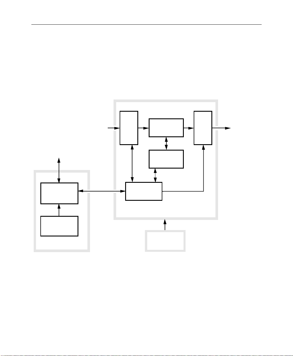
Physical Description
The switcher consists of three main areas: the Control Panel, the
Signal Processor Frame, and the Frame Power Supply (see
Figure 1-1). The electronic circuitry in the Model 3000 is primarily
contained on circuit boards and modules in the Signal Processor
Frame and Control Panel.
Signal Processor Frame
The Signal Processor Frame is a large rack-mounted unit that
houses the system controller, effects logic, video and key
processors, and input/output interfaces.
In addition to the basic system, a typical system may have several
options such as Chroma Keyers, Secondary W ipe Generators, and
Frame Store. Most options are available as circuit board modules
to be installed in the Signal Processor Frame.
Refer to the Model 3000 System Information manual for a
complete description of the Signal Processor.
Physical Description
A main processor (HOS, or Head-Of-State) and separate M/E
processors reside within the Signal Processor Frame. Since each
M/E has its own processor, failure of one processor may not
disable the entire switcher. Individual effects can continue to
operate independently in a limited capacity.
1-5
Page 22
Section 1 — System Overview
Power Supplies
Two power supplies are used in the basic Model 3000 system: a
control panel power supply, located in the control panel tub, and
a 19" rack mount power supply used by the Signal Processor
Frame. Optional Redundant power supplies are available.
TP0348-01
Pointing
Device
(bitpad)
CONTROL
PANEL
CONTROL PANEL
POWER SUPPLY
Control Panel
Figure 1-1. Simplified Block Diagram of the Model 3000 Switcher
Video/Key
Signals In
Frame
Panel
Link
INPUTS
AND
CROSSPOINTS
CONTROLLER/
HEAD-OF-STATE
PROCESSOR
EFFECTS
PROCESSORS
EFFECTS
LOGIC
to
OUTPUT
AND
EXPAN-
SION
Signal
Video/Key
Signals Out
Processor
Frame
Frame
Power Supply
1-6
Page 23
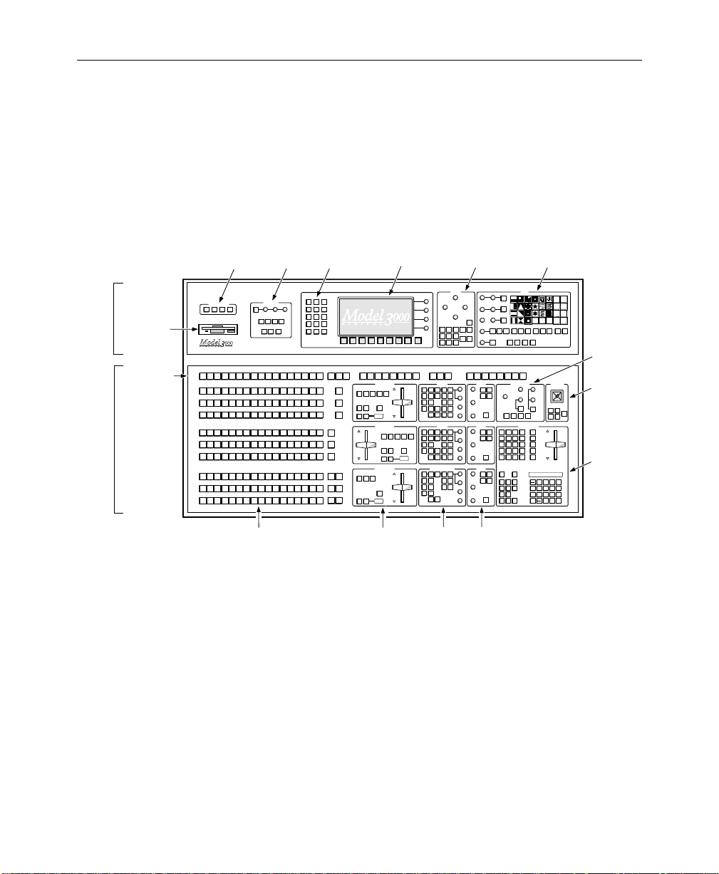
Control Panel
Physical Description
The Control Panel is the operator interface for the Model 3000
system. The operator performs all actions via physical buttons
and knobs and a software-driven menu.
Upper
Panel
Lower
Panel
12B. Menu
Display
Buttons
M/E
CONFG
STAT
MODE
CHR
KEYER
WIPE
KEY
OPACITY
KEY
AUX
E-MEM
FRAME
FIELD
MASK
STORE
BUS
2
FRAME
MATTE
MASK
STORE
LAST
DISK
MISC
MENU
M/E 1
M/E 2
BKGD
BKGD
SHIFT
141312111098765432BLACK
PGM
PGM
1
2
KEY 1
BKGD
BKGD
M / E
141312111098765432BLACK
SHIFT
1
2
2
KEY 2
BKGD
BKGD
M / E
141312111098765432BLACK
SHIFT
1
2
2
BKGD
BKGD
M / E
141312111098765432BLACK
SHIFT
1
2
2
KEY 1 UNCAL
BKGD
BKGD
M / E
141312111098765432BLACK
SHIFT
1
2
1
KEY 2 UNCAL
BKGD
BKGD
M / E
141312111098765432BLACK
SHIFT
1
2
1
BKGD
BKGD
M / E
141312111098765432BLACK
SHIFT
1
2
1
M / E2M / E
BKGD
BKGD
141312111098765432BLACK
SHIFT
1
1
2
M / E2M / E
BKGD
BKGD
141312111098765432BLACK
SHIFT
1
1
2
M / E2M / E
BKGD
BKGD
141312111098765432BLACK
SHIFT
1
2
1
PGM
UNCAL
UNCAL
UNCAL
UNCAL
UNCAL
UNCAL
UNCAL
UNCAL
UNCAL
12A. Menu
AUX 1-4 EFFECTS SEND ONLY
M/E 1BM/E 1AM/E 1
KEY 1
TRANSITION
EFF
EFF
EFF
EFF
SEND
SEND
SEND
SEND
KEY2KEY1BKGD
BKGD
A
B
ON
ONON
OVERONOVER
LAYERED
PST
WIPEMIX
BLK
AUTO
CUT
TRAN
060
TRANSITION
SEND
BKGD
CUT
TRANSITION
DSK2DSK
BKGD
1
ON
OVERONOVER
PST
BLK
AUTO
CUT
TRAN
060
Subpanels
Display
M/E 1
M/E 2
KEY 2
B
KEY
PRIOR
EFF
EFF
SEND
A
B
ONON
LAYERED
WIPEMIX
AUTO
TRAN
M/E 2
A
EFF
EFF
SEND
SEND
KEY2KEY1BKGD
ON
OVERONOVER
PST
BLK
060
EXIT
M/E 2
M/E 2
KEY 1
KEY 2
KEY
PRIOR
Subpanels
BOX
M / E 1
KEY 1
M / E 1
KEY 2
PREVIEW ONLY
M/E 2
M/E 1
PVW
PVW
KEYERS
BORD
NORM
SHDW
KEY
FORCE
INH
OVER
MASK
MASK
SPLIT
MATTE
VIDEO
KEY
FILL
FILL
LUM
LIN
CHR
KEY
KEY
KEY
KEY
BKGD
ON
A
B
KEYERS
BORD
NORM
SHDW
KEY
FORCE
INH
OVER
MASK
MASK
VIDEO
MATTE
SPLIT
FILL
FILL
KEY
LUM
LIN
CHR
KEY
KEY
KEY
KEYONKEY
BKGD
BKGD
A
B
DOWNSTREAM KEYERS
BORD
NORM
SHDW
KEY
INH
OVER
MASK
VIDEO
MATTE
SPLIT
FILL
FILL
KEY
LIN
LUM
KEY
KEY
DSK
KEY
DSK
2
ON
1
4. Keyer
MASKS
LEFT RIGHT
BOTTOM / CLIP
PRI
WIPE
M / E 2
KEY 1
M / E 2
KEY 2
DSK
PVW
OUT
EXTD
LINE
SHOW
INV
KEY
AUTO
VIDEO
SEL
KEY
KEY
PRI
SEC
PST
PST
PTTN
PTTN
KEY
KEY1BKGD
2
OUT
EXTD
LINE
SHOW
INV
KEY
AUTO
VIDEO
SEL
KEY
KEY
SEC
PRI
PST
PST
PTTN
PTTN
KEY
2
1
OUT
EXTD
LINE
SHOW
INV
KEY
AUTO
VIDEO
SEL
KEY
KEY
11. Mask
Subpanel
TOP / GAIN
MASK
SEC
BUS
WIPE
DSK
1
FORCE
MASK
DSK
2
SIZE / POS
OPACITY
GAIN
CLIP
SIZE / POS
OPACITY
GAIN
CLIP
SIZE / POS
OPACITY
GAIN
CLIP
15.
Floppy
Disk
Drive
17.
Preview/
Mask/Aux
Bus
14. External
Interface
Subpanel
Grass Valley Group
EXTERNAL INTERFACE
PVW
AUX
13. Frame
Store
Subpanel
®
FRAME STORES
DROP
AUXPERPHGPIEDIT
SHDW
H
POSITIONVPOSITION
FIELD
GRABFRZE
1
KEY
VIDEO
STORE
STORE
KEY
A
B
KEY
A
B
DSK
PGM
PST
1. Source Selection 2. Transition
Figure 1-2. Functional Areas of Model 3000-2 Control Panel
SYMMETRY
SOFTNESS
OPACITY
WIDTH
MASK
INV
PRESET SIZE
ASPECT
ROTATION TYPE
MASK
STORE
ROT
POS
ROTATE
INH
MASK
PATT
MIX
PATTERN MIX
BUS DELEGATE
AUX1AUX2AUX3AUX
PVW MASK
MATTES
PRI
SEC
WIPE
WIPE
WASH
WASH
HUE/
SOFTNESS
FLAT
MATTE
MATTE
2
K1 FILL K1 BORD
K2 FILL K2 BORD
SATURATION/
OFFSET
PRI WIPE SEC WIPE
MATTE
SEL
BRIGHTNESS
MATTES
PRI
SEC
WIPE
WIPE
WASH
WASH
HUE/
SOFTNESS
FLAT
MATTE
MATTE
2
K1 FILL K1 BORD
K2 FILL K2 BORD
SATURATION/
OFFSET
PRI WIPE SEC WIPE
MATTE
SEL
BRIGHTNESS
MATTES
USER
SEC
DEF
WIPE
WASH
WASH
HUE/
SOFTNESS
FLAT
MATTE
MATTE
2
K1 FILL K1 BORD
K2 FILL K2 BORD
SATURATION/
OFFSET
BKGD 1 BKGD 2
MATTE
SEL
BRIGHT / TEX
5. Matte
Subpanels
10. Wipe
Subpanel
8.
Chroma
Keyer
Subpanel
9.
Positioner
Subpanel
6.
Effects
Memory
(E-MEM®)
Subpanel
TP0348-06B
WIPE
SOFT
BORD
ASPCT
WIPE DIRECTION
ROT
ROT
NORM REV
SPD
MAG
DELEGATE
M / E 1
M / E 1
SEC
PRI
WIPE
WIPE
AUX 5 AUX
4
CHROMA KEYERS
R
SELECTIVITY
Y
M
B
G
C
SHADOW
OPACITY
HUE
SHDW
ON
M/E 1
M/E 1
M/E 2
KEY 1
KEY 2
KEY 1
EFFECTS MEMORY
CLR
CONST
WORK
GET
DUR
BUFR
GO
PREV
NEXT
TO
TIME
EFF
TIME
MARK
DUR
ALIGN
BLOCK
COPY
CUTMARK
PASTE
INSRT
INSRT
MOD
MOD
BEFOR
AFTER
EVENT
GLOBL
AUTO
ENABLES
INHIB
RCL
DPM
ENABL
M/E
1
ALL
1
DPM
M/E
MISC
2
2
DPM
BKGD
3
PGM
DPM
DSK
PST
4
FLIP
FLOP
M/E 2
M / E 2
SEC
PRI
WIPE
WIPE
6
LUM
CHROMA
BKGD
SUPR
M/E 2
KEY 2
RE
PUT
WIND
GO
FLIP
TO
FLOP
KF
KF
REV
DUR
AUTO
RUN
STOP
NEXT
KF
8888888888888888
LOCK
LRN
SEQ
EFF
DIS
BANK
USER
USER
2
1
USER
USER
4
3
USER5USER
6
LEARN
USER
RANDOM
MENU
USER
TEXTURE
WIPE
WIPE
UNDO
PATTERN MODIFIERS
POSITIONER
H
POS
POS
SPLIT
MULTIVMULTI
NORM
AUTO
POSITIONER
M/E 1
M/E 1
PRI
SEC
WIPE
WIPE
CTR
M/E 2
M/E 2
PRI
SEC
WIPE
WIPE
8
9
RUN
7
BANK
5
6
4
1
BANK
2
3
1
2
UNDO
TRAN
ENTER
0
RATE
•
1-7
Page 24
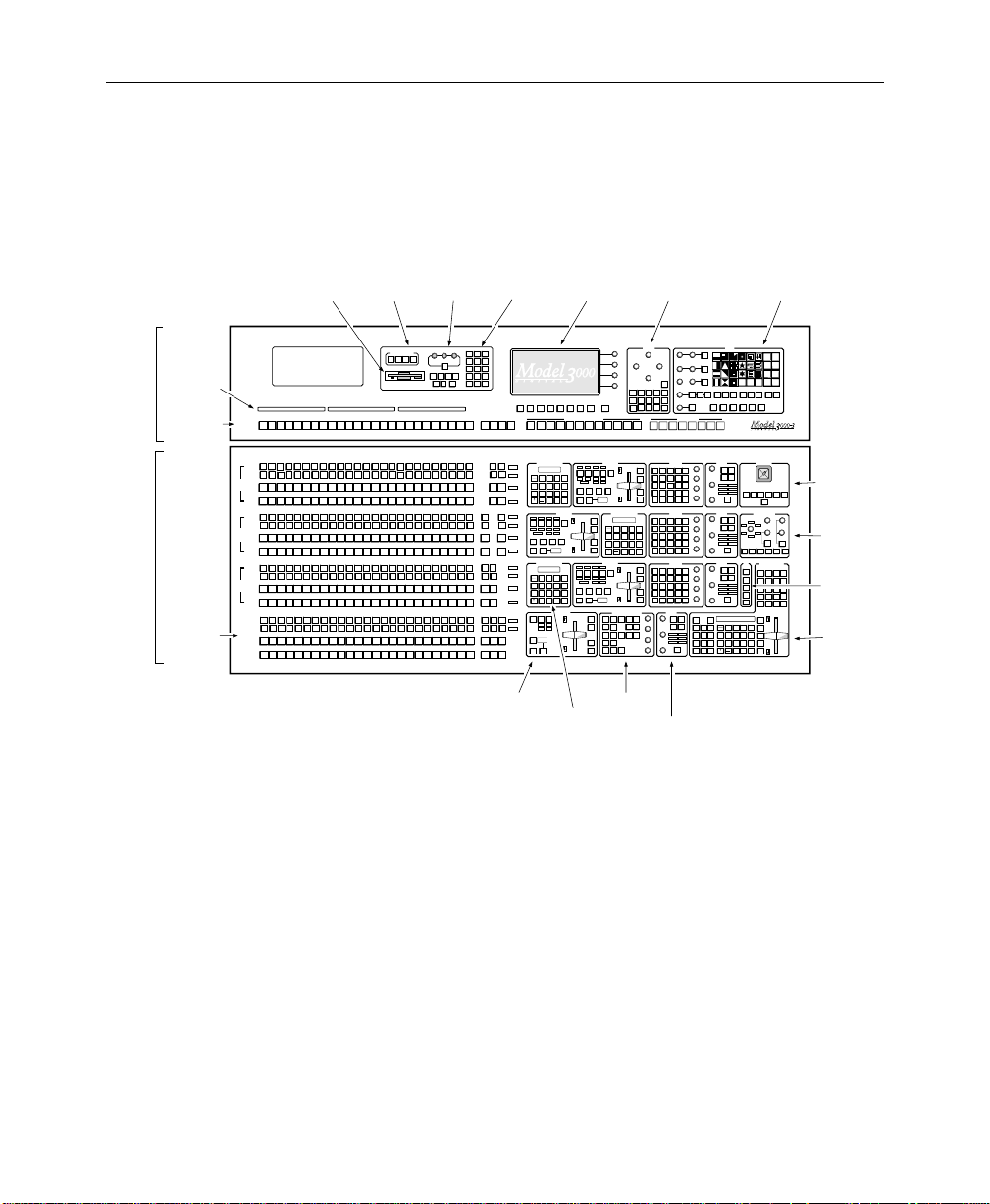
Section 1 — System Overview
The Control Panel also provides connectors for the Mask Draw
option and the data link to the Signal Processor Frame.
Upper
Panel
Lower
Panel
16.
Crosspoint
Name
Display
(Option)
17.
Preview/
Mask/Aux
Bus
1.
Source
Selection
15.
Floppy
Disk Drive
Grass Valley Group
PVW/AUX
Grass Valley Group
BLK 15
KEY 1
KEY 2
M/E
A
1
B
KEY 1
KEY 2
M/E
A
2
B
KEY 1
KEY 2
M/E
A
3
B
DSK 1
DSK 2
PROGRAM
PRESET
14. External
Interface
Subpanel
13. Frame
Store
Subpanel
FRAME STORES
EXTERNAL INTERFACE
AUXPERPHGPIEDIT
H
OPACITY
POSITIONVPOSITION
DROP
SHDW
FIELD
FIELD
GRABFRZE
2
1
KEY
VIDEO
MASK
STORE
STORE
STORE
141312111098765432BLACK 15 2322212019181716 SHIFT
141312111098765432
141312111098765432BLK 15
141312111098765432BLACK
15
141312111098765432BLACK
15
141312111098765432
141312111098765432BLK 15
141312111098765432BLACK
15
141312111098765432BLACK
15
141312111098765432
141312111098765432BLK 15
141312111098765432BLACK
15
141312111098765432BLACK
15
141312111098765432
141312111098765432BLK 15
141312111098765432BLACK
15
141312111098765432BLACK
15
2322212019181716
2322212019181716 SHIFT
2322212019181716
2322212019181716
2322212019181716BLK 15
2322212019181716 SHIFT
2322212019181716
2322212019181716
2322212019181716BLK 15
2322212019181716 SHIFT
2322212019181716
2322212019181716
22212019181716BLK 15
23
22212019181716
23 SHIFT
22212019181716
22212019181716
2323SHIFT
12B. Menu
Display
Buttons
M/E
CONFG
STAT
MODE
CHR
KEYER
WIPE
KEY
KEY
AUX
E-MEM
FRAME
BUS
FRAME
MATTE
MASK
STORE
LAST
DISK
MISC
MENU
M/E 2
M/E 1
M/E 3
COLOR
PGM
PGM
PGM
PGM
BKGD
M / E2M / E
CLR
SHIFT
UNCAL
3
BKGD
M / E
M / E
CLR
UNCAL
3
2
BKGD
M / E
M / E
COLOR
SHIFT
UNCAL
2
3
BKGD
M / E
M / E
COLOR
SHIFT
UNCAL
2
3
BKGD
M / E
M / E
CLR
UNCAL
SHIFT
3
1
BKGD
M / E
M / E
CLR
UNCAL
1
3
BKGD
M / E
M / E
COLOR
UNCAL
SHIFT
1
3
BKGD
M / E
M / E
COLOR
UNCAL
SHIFT
1
3
BKGD
M / E
M / E
CLR
UNCAL
SHIFT
2
1
BKGD
M / E
M / E
CLR
UNCAL
2
1
BKGD
M / E
M / E
COLOR
UNCAL
SHIFT
1
2
BKGD
M / E
M / E
COLOR
UNCAL
SHIFT
1
2
BKGD
M / E
M / E
M / E
CLR
SHIFT
UNCAL
3
2
1
BKGD
M / E
M / E
M / E
CLR
UNCAL
3
1
2
BKGD
M / E
M / E
COLOR
M / E
SHIFT
3
1
BKGD
2
M / E
M / E
COLOR
M / E
1
3
BKGD
2
2. Transition
Subpanels
12A. Menu
Display
F8 EXITF7F6F5F4F3F2F1
AUX 1-4 EFFECTS SEND ONLY
M/E 2
M/E 2
M/E 1AM/E 1BM/E 1
M/E 1
M/E 2
B
KEY 1
KEY 2
KEY 1
KEY 2
A
EFFECTS MEMORY
EFF EFF EFF EFF
88888888
BKGD
A
B
LOCK
9
RUN
708
ONON
LRN
LAYERED
BANK
SEQ
5
4
6
0
BANK
EFF
32
1
1
DIS
AUTO
UNDO
TRAN
CUT
ENTER
TRAN
RATE
BANK
•
TRANSITION
EFF EFF EFF EFF
KEY 1
CUT
KEY
KEY2KEY1BKGD
BKGD
PRIOR
A
B
KEY 1
ON
ONON
MIX
OVERONOVER
LAYERED
PST
KEY 2
EFFWIPEMIX
BLK
CUT
KEY 2
AUTO
CUT
LOCK
LRN
SEQ
EFF
DIS
BANK
BKGD
PST
BLK
CUT
Effects Memory
TRAN
888
EFFECTS MEMORY
EFF EFF EFF EFF
88888888
BKGD
9
RUN
708
BANK
5
4
6
0
BANK
1
32
1
UNDO
TRAN
CUT
ENTER
RATE
•
TRANSITION
DSK
DSK
2
1
ON
OVERONOVER
060
AUTO
TRAN
3. M/E
Subpanels
MIX
A
B
ONON
LAYERED
AUTO
TRAN
DSK 1
CUT
DSK 1
MIX
DSK 2
CUT
DSK 2
MIX
LEFT RIGHT
BOX
WIPE
M / E 2
M / E 1
KEY 1
KEY 1
M / E 2
M / E 1
KEY 2
KEY 2
M/E 3
M/E 2
M/E 3
M/E 3
M/E 3
B
A
KEY 1
KEY 2
TRANSITION
KEY 1
CUT
KEY
KEY2KEY1BKGD
PRIOR
KEY 1
ON
MIX
OVERONOVER
PST
KEY 2
EFFWIPEMIX
BLK
CUT
KEY 2
MIX
888
EFFECTS MEMORY
88888888
LOCK
9
RUN
708
LRN
BANK
SEQ
5
4
6
0
BANK
EFF
32
1
1
DIS
UNDO
TRAN
ENTER
RATE
BANK
•
TRANSITION
KEY 1
CUT
KEY
KEY2KEY1BKGD
PRIOR
KEY 1
ON
MIX
OVERONOVER
PST
KEY 2
EFFWIPEMIX
BLK
CUT
KEY 2
MIX
888
DOWNSTREAM KEYERS
OUT
EXTD
BORD
NORM
SHDW
LINE
SHOW
KEY
INH
INV
KEY
OVER
MASK
AUTO
MATTE
VIDEO
VIDEO
SPLIT
SEL
FILL
FILL
KEY
KEY
KEY
LUM
LIN
KEY
KEY
DSK
DSK
KEY
1
2
ON
4. Keyer
Subpanels
11. Mask
Subpanel
MASKS
TOP / GAIN
BOTTOM / CLIP
MASK
INV
MASK
SEC
PRI
MASK
BUS
WIPE
STORE
INH
M / E 3
DSK
MASK
KEY 1
1
M / E 3
DSK
FORCE
KEY 2
2
MASK
AUX 1
PVW MASK
A/B
KEYERS
BORD
NORM
SHDW
INH
KEY
FORCE
MASK
OVER
MASK
SPLIT
MATTE
VIDEO
KEY
FILL
FILL
CHR
LUM
LIN
KEY
KEY
KEY
KEY
BKGD
BKGD
ON
B
A
KEYERS
BORD
NORM
SHDW
INH
KEY
FORCE
MASK
OVER
MASK
SPLIT
MATTE
VIDEO
KEY
FILL
FILL
CHR
LUM
LIN
KEY
KEY
KEY
KEY
BKGD
BKGD
ON
B
A
KEYERS
BORD
NORM
SHDW
INH
KEY
FORCE
MASK
OVER
MASK
SPLIT
MATTE
VIDEO
KEY
FILL
FILL
CHR
LUM
LIN
KEY
KEY
KEY
KEY
BKGD
BKGD
ON
B
A
MATTES
USER
WASH
BORDERLINE
HUE/
SIZE / POS
SOFTNESS
FLAT
MATTE
BORDERLINE
K1 FILL K1 BORD
OPACITY
K2 FILL K2 BORD
SATURATION/
OFFSET
PRI WIPE SEC WIPE
GAIN
CLIP
BRIGHT/TEX
5. Matte
Subpanels
WIPE
SOFT
SYMMETRY
SOFTNESS
BORD
OPACITY
WIDTH
ASPCT
PRESET SIZE
ASPECT
ROTATION TYPE
WIPE DIRECTION
ROT
ROT
ROT
FLIP
NORM REV
POS
SPD
MAG
FLOP
ROTATE
DELEGATE
M / E 1
M / E 1
M / E 2
PATT
PRI
SEC
PRI
MIX
WIPE
WIPE
WIPE
PATTERN MIX
BUS DELEGATE
AUX 2
AUX 3
AUX 4
AUX 6
AUX 5
A/B
A/B
A/B
A/B
A/B
MATTES
PRI
SEC
OUT
WIPE
WIPE
EXTD
LINE
WASH
WASH
BORDERLINE
HUE/
SIZE / POS
SOFTNESS
MATTE
FLAT
SHOW
INV
2
MATTE
KEY
BORDERLINE
AUTO
OPACITY
VIDEO
K1 FILL K1 BORD
SEL
KEY
KEY
K2 FILL K2 BORD
SATURATION/
PRI
SEC
OFFSET
GAIN
PST
PST
PRI WIPE SEC WIPE
PTTN
PTTN
MATTE
KEY
KEY
SEL
1
2
CLIP
BRIGHTNESS
MATTES
PRI
SEC
OUT
WIPE
WIPE
EXTD
LINE
WASH
WASH
BORDERLINE
HUE/
SIZE / POS
SOFTNESS
MATTE
FLAT
SHOW
INV
2
MATTE
KEY
BORDERLINE
AUTO
OPACITY
VIDEO
K1 FILL K1 BORD
SEL
KEY
KEY
K2 FILL K2 BORD
SATURATION/
OFFSET
PRI
SEC
GAIN
PST
PST
PRI WIPE SEC WIPE
PTTN
PTTN
MATTE
KEY
KEY
SEL
1
2
CLIP
BRIGHTNESS
MATTES
PRI
SEC
OUT
WIPE
WIPE
EXTD
LINE
WASH
WASH
BORDERLINE
HUE/
SIZE / POS
SOFTNESS
MATTE
FLAT
SHOW
INV
2
MATTE
KEY
BORDERLINE
AUTO
OPACITY
VIDEO
K1 FILL K1 BORD
SEL
KEY
KEY
K2 FILL K2 BORD
SATURATION/
OFFSET
PRI
SEC
GAIN
PST
PST
PRI WIPE SEC WIPE
PTTN
PTTN
MATTE
KEY
KEY
SEL
1
2
CLIP
BRIGHTNESS
SEC
AUTO
GLOBL
DEF
WIPE
8888888888888888
RCL
INHIB
WASH
MATTE
DPM
LOCK
ENABL
M/E
708
2
1
ALL
1
LRN
DPM
M/E
SEQ
5
4
MISC
2
2
M/E
DPM
EFF
1
BKGD
3
3
DIS
MATTE
UNDO
DPM
PGM
DSK
SEL
4
PST
BANK
•
Figure 1-3. Functional Areas of Model 3000-3 Control Panel
10. Wipe
Subpanel
USER
USER
2
1
USER
USER
4
3
USER5USER
6
LEARN
USER
RANDOM
MENU
USER
TEXTURE
WIPE
WIPE
UNDO
POSITIONER
PATTERN MODIFIERS
H
POS
POS
SPLIT
MULTIVMULTI
NORM
AUTO
M/E 2
M / E 3
M/E 3
SEC
PRI
SEC
WIPE
WIPE
WIPE
POSITIONER
M/E 2
M/E 2
M/E 1
M/E 2
M/E 2
M/E 1
SEC
SEC
PRI
PRI
PRI
SEC
CTR
CHROMA KEYERS
R
LUM
SELECTIVITY
Y
M
G
B
C
SHADOW
CHROMA
OPACITY
SHDW
BKGD
ON
SUPR
M/E 3
M/E 3
M/E 1
M/E 1
M/E 2
M/E 2
KEY 1
KEY 2
KEY 1
KEY 2
KEY 1
KEY 2
EFFECTS MEMORY
PVW
PVW
CLEAR
CONST
PRI
GET
WORK
PUT
DUR
BUFR
M / E
GO
GO
1
TO
NEXT
PREV
TO
KF
TIME
M / E
KF
TIME
MARK
EFF
2
BLOCK
DUR
ALIGN
DUR
M / E
3
CUTMARK
PASTE
COPY
DSK
INSRT
MOD
INSRT
MOD
BEFOR
EVENT
AFTER
RE
WIND
FLIP
9
RUN
FLOP
BANK
6
REV
0
BANK
AUTO
32
1
RUN
STOP
TRAN
ENTER
NEXT
RATE
KF
9.
Positioner
Subpanel
8.
Chroma
Keyer
Subpanel
7.
Preview
Subpanel
6.
Master
Effects
Memory
Subpanel
TP0702-06B
1-8
Page 25

Video and Key Inputs and Outputs
Inputs
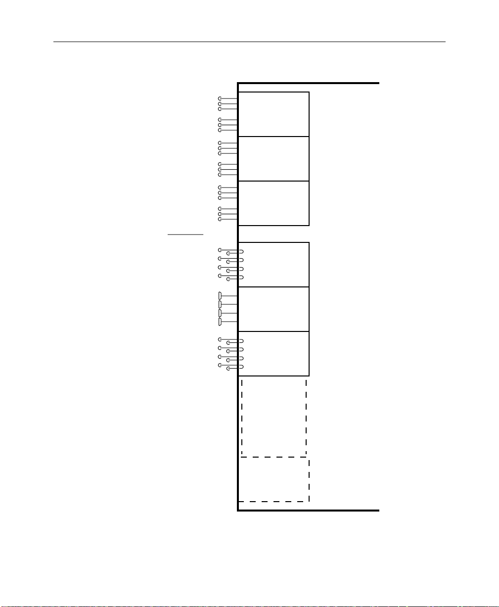
Three types of input options may be installed in the Signal
Processor Frame to suit the needs of your installation. Each input
module supports four inputs and provides auto-timing of each
input.
The following types of input modules are available.
Video and Key Inputs and Outputs
NOTE:
Each of these inputs can be treated by the switcher as either a
video input or a key input.
■
Analog 10-bit Composite Quad Input Module – Provides
noise filtering, anti-aliasing, and auto-timing of the input
signals, then performs an analog-to-digital conversion of each
signal and multiplexes the data onto a video or key bus.
Digital Bit-Parallel Quad Input Module – Converts the inputs
■
from ECL to TTL, auto-times the signals, and multiplexes
them onto the video or key bus.
Digital Bit-Serial Quad Input Module – Decodes the inputs
■
from serial to parallel, auto-times the signals, and multiplexes
the data onto the video or key bus.
In addition, RGB input modules are available with the Dual
Chroma Keyer option. Each module supports two sets of RGB
inputs (see Figure 1-4).
Refer to the Startup and Configuration section of this manual for
information on assigning input formats and adjusting timing.
1-9
Page 26
Section 1 — System Overview
DUAL RGB
INPUT
MODULE
DUAL RGB
INPUT
MODULE
Input Modules
Up to 3 Dual RGB
(Any mix of module types)
Up to 16 Quad Input Modules
DUAL RGB
INPUT
MODULE
QUAD
ANALOG INPUT
MODULE
QUAD
PARALLEL DIGITAL
INPUT MODULE
QUAD
SERIAL DIGITAL
INPUT MODULE
0702-03
Module Cells A1 through A3
Signal
Processor
Frame
Module Cells C1 through C16
1-10
Figure 1-4. Video and Key Inputs
Page 27

Outputs
Video and Key Inputs and Outputs
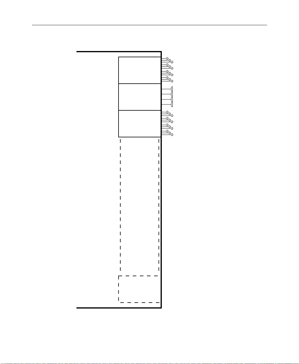
Regardless of the format of the input signals, the Signal Processor
can provide outputs in any composite format.
Signal outputs are provided by output modules installed in the
Signal Processor Frame (see Figure 1-5). Each output module
provides four video/key signal outputs of a given type, with up
to three buffered outputs per signal channel.
Since each output module
cell
is dedicated to specific functions,
the format of each output signal is determined by the type of
output module installed in that cell. The following choices of
output modules are available:
Composite Analog (4 signal channels; 3 outputs of each
■
signal)
■
Parallel Digital (4 signals; 1 output of each signal)
■
Serial Digital (4 signals; 3 outputs of each signal)
Standard (Analog) outputs include:
■
(DSK) Program Video
■
(DSK) Program Key
■
Mask Bus
■
Switched Preview Video
Optional outputs (Analog and/or Digital) include:
■
M/E 1 Program Video, M/E 1 Program Key
■
M/E 1 Preview Video
■
M/E 2 Program Video, M/E 2 Program Key
■
M/E 2 Preview Video
■
M/E 3 Program Video, M/E 3 Program Key (3000-3 only)
■
M/E 3 Preview Video (3000-3 only)
■
DSK Preview
■
DSK Preview Video
■
Aux Buses 1A-4B, Aux Buses 5A-7B
■
Clean Feed Video
■
Frame Store Video and Key
1-11
Page 28
Section 1 — System Overview
Signal
Processor
Frame
QUAD
ANALOG OUTPUT
MODULE
QUAD
PARALLEL DIGITAL
OUTPUT MODULE
QUAD
SERIAL DIGITAL
OUTPUT MODULE
Module Cells A4 through A17
4 Signal Channels
per Module
3 Outputs of
each Signal
4 Signal Channels
per Module
1 Output of
each Signal
4 Signal Channels
per Module
3 Outputs of
each Signal
(Any mix of module types)
Up to 14 Quad Output Modules
0348-04
1-12
Figure 1-5. Video and Key Outputs
Page 29

Functional Description
Overview
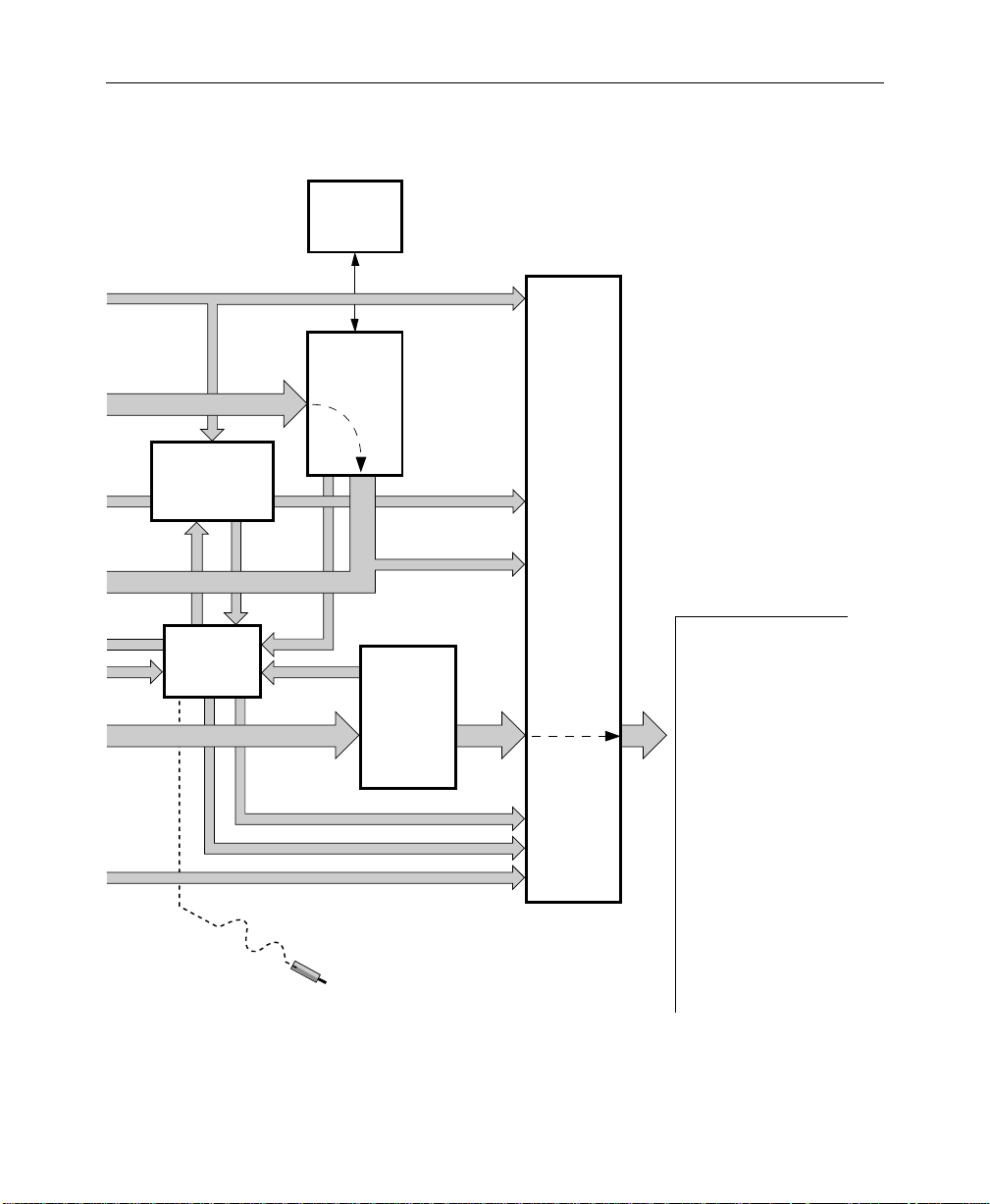
Figure 1-6 shows the video flow in a typical Model 3000 switching
system.
Video and key signals enter the Input Section of the Model 3000,
which consists of analog, parallel digital, and/or serial digital
modules. The analog signals are converted to digital format, and
all inputs are timed and conditioned.
The digital signals are then passed to the V ideo and Effects Section
where keying and mixing take place. This section also provides
effect modifications, such as wipes, that can be applied to selected
inputs.
In the Output Section, digital video and key signals are converted
to any desired composite format (analog, parallel digital, or serial
digital), as predetermined by the type of output modules
installed, before leaving the Signal Processor.
Functional Description
1-13
Page 30

Section 1 — System Overview
Video Processing
Input video and key signal selections are made by the Crosspoint
Matrix under control of the system Controller, according to
operator assignments entered via the Control Panel.
In addition to primary (external) video, secondary (internal)
sources such as Masks, M/E re-entry video, and optional Frame
Store are available as inputs to the crosspoint matrix.
Two sets of RGB signals may be applied per optional Dual RGB
input module. These inputs are forwarded to a Dual Chroma
Keyer module.
Keyers in each Mix/Effects bank provide outputs to the Effects
Loop crosspoints for sending outside the switcher for external
processing or for routing to the M/E mixers and wipe generators.
The Effects Send outputs can also be directed to the Frame Store
option for image capture. One optional Effects Loop Crosspoint
module services all three Mix/Effects banks.
1-14
Page 31

Functional Description
Each M/E has two keyers and two background buses (A and B) as
inputs. In standard mode, Keyers 1 and 2 can be mixed into a
composite video and key which can be forwarded to the DSK,
another other M/E, or output. In layered mode, Backgrounds A
and B are also used as keyers that operate in a manner similar to
Keyers 1 and 2.
Optional preview capability allows monitoring of sources at
certain points in the signal flow. You can preview video from the
M/E mixers, Flip/Flop Mix and DSK mixer, switched preview
bus, or mask bus.
Eight level-sensitive GPI inputs are provided. You can assign each
of these inputs via the GPI Input menu to perform a specific
function when triggered.
The editor interface consists of an asynchronous RS-422, 38.4K
baud serial communications port, managed by a communications
processor .
1-15
Page 32

Section 1 — System Overview
RGB
Inputs
Video Signals
In
Key Signals
In
0702-05L
DUAL
RGB INPUT
MODULES
QUAD
INPUT
MODULES
ANALOG,
PARALLEL
DIGITAL,
AND
SERIAL
DIGITAL
Clocks
SYNC
GENERATOR
Black,
Back-
ground,
and
Test
Signals
DUAL
CHROMA
KEYERS
80 X 48
VIDEO
CROSSPOINT
MATRIX
M/E1,
M/E2 & M/E3
Chr. Key
M/E
Video
and
Key
MODULES –
QUAD
KEYER
M/E 1,
M/E 2,
& M/E 3
Aux Bus
1A-4B
EFFECTS
LOOP
CROSS-
POINTS
Frame Store Video and Key
M/E Program Video and Key
Clipped Mask and
Mask Store Video
Switched Preview and Mask
Program, Preset, and DSK Video and Key
Aux Bus 5A-7B Video and Key
1-16
CONTROL PANEL
CONTROLLER
(control buses not
shown for simplicity)
To/From
All Circuits
Page 33
Aux Bus 1A-4B
Video and Key
SECONDARY
WIPE
OPTION
M/E 1
& M/E 2
MIXERS
Functional Description
0348-05R
FRAME STORE
FOR VIDEO, KEY,
AND MASK
STORAGE
Mask
Store
Input
PREVIEW
Mask
Store
Output
M/E Pvw
Video
DSK Pvw
Video
Mask and
Switched Preview
M/E and DSK Preview
DIAGNOSTIC
PROBE
Frame Store
Video
and Key
M/E 1 and M/E 2
Program Video
and Key
Program
PGM/PST
MIXER
AND
DUAL DSK
Video
& Key
& Clean
Feed
Video
NOTE:
Primary Video Paths are
Indicated by Wide Arrows
QUAD
OUTPUT
MODULES
ANALOG,
PARALLEL
DIGITAL,
AND
SERIAL
DIGITAL
Outputs
Frame Store Video and Key
M/E 1 and M/E 2
Program Video and Key
Program Video and Key
Clean Feed Video
DSK Preview Video
Mask
Switched Preview
M/E1 and M/E 2
Preview
DSK Preview
Aux Bus Video and Key
Figure 1-6. Video Flow Diagram of Typical Model 3000 Switching System
1-17
Page 34

Section 1 — System Overview
Description of Options
The following options are currently available for the Model 3000
Switcher. For more details on these options, refer to the
appropriate subpanel descriptions later in this manual.
Dual Chroma Keyer
Up to six analog component (RGB, YUV, or Betacam®) or
composite inputs can be chroma keyed, two per Dual Chroma
Keyer module. Each module is added to a specific M/E.
Borderline
®
Key Edge Generation
Borderline Key Edge Generators are available for each keyer in the
switcher. The Borderline feature is implemented as a mezzanine
board that plugs onto the Keyer module of any M/E.
Each Borderline generator supports 1, 2, or 3 line wide borders for
border and outline modes and 1 to 6 line wide edges for shadow
and extrude modes. Fill within the key edges may be either video
or matte.
Secondary Wipe Generator
A Secondary Wipe Generator module provides a second pattern
for each of the M/E systems. Only one module is required for
enhancing all mix/effect systems.
1-18
Page 35

Safe Title/Action Area Generator
The Safe Title/Action Area Generator provides up to four
different patterns that can be superimposed on the switched
preview output of the switcher . It may be used to define a safe title
area, safe action area, or for screen centering and horizontal/
vertical alignment of picture elements.
Mix/Effects Clean Feed
A clean feed output of the wipe/mix signals (the two backgr ound
bus video signals without any keys added) is provided by a LookAhead Preview mezzanine board installed on the Mixer and
Primary Wipe Generator module.
Frame Store
The Frame Store option allows storage and retrieval of images at
a resolution of 10 bits. Either two two-field pictures and keys or
one four-field picture and key can be frozen in the Frame Stor e. A
two-field mask store is also provided.
Description of Options
Effects Send
Effects Send provides a method of integrating digital effects
devices into the switcher mix/effects system. Up to four send
channels can be used to route the video and key from an M/E to
and from an external digital effects system.
1-19
Page 36

Section 1 — System Overview
Tally Output
The Tally Relay module provides tally outputs that reflect the
switcher status. A rear-panel interconnect board provides the
relay contacts at two connectors for on-air Tally A and on-air
Tally B. Pin-outs for the Tally connectors are given in the
Installation section of the System Information manual.
Tally Expansion
The T ally Expansion Option increases the number of tally outputs
from the Model 3000 Switcher. An unlimited number of Tally
Expansion frames, each with up to three tally modules, can be
added to the switcher.
Remote Auxiliary Bus Control Panels
Three models of Remote Aux Control Panels are available for
controlling your switcher auxiliary buses from a remote location.
The one- and two-RU panels each control a single aux bus; the
three-RU panel provides delegated control of any number of aux
buses.
Chroma Key Auto Setup
The Chroma Key Auto Setup option is a software option that
automatically sets up a chroma key when you identify the
background color. This option requires the presence of the Frame
Store option.
1-20
Page 37

Startup & Configuration
2
Introduction
This section describes turning on the Model 3000 and configuring
it to your facility. Included are procedures for setting the system
clock, configuring inputs and outputs, configuring external
interfaces, and setting user preferences. The following items are
discussed in this manual section:
■ Powering Up on page 2-2
■ Software Setup on page 2-7
■ Setting System Parameters on page 2-10
■ Configuring Inputs on page 2-14
■ Configuring External Interfaces on page 2-32
■ Formatting Aux Buses on page 2-53
■ Setting User Preferences on page 2-54
■ Setting User-Defined System Defaults on page 2-63
■ Operating Notes on page 2-64
2-1
Page 38

Section 2 — Startup & Configuration
Powering Up
The Model 3000 is designed for continuous operation. It may
already be on and operating; however, the following power-up
procedure is provided in the event that it isn’t:
1. Turn on the power switch on the front of the Signal Pr ocessor
Power Supply. Verify that the power supply voltage LEDs on
the front of the Power Supply are lit and that the fans in the
Processor are on. If the Processor is equipped with a
redundant power supply, turn on that supply also.
2. Raise the Control Panel and turn on the power supply switch.
If a redundant power supply is included in the Control Panel,
turn on both power supply switches. Verify that the green
RUN LED on the control panel CPU Board is lit. This board is
located in the middle of the control panel tub on the Model
3000-2, and in the upper control panel in the Model 3000-3.
3. Verify that the Menu Display on the upper Contr ol Panel is on
and displaying the “Grass Valley” sign-on logo.
Boot-Up
2-2
4. Verify that the pushbutton lamps on the panel ar e on and that
the E-MEM and Transition subpanel readout LEDs are on.
If one of these indications is incorrect, turn off all power supplies
and refer to the Diagnostics and Troubleshooting section of the
Installation and Service manual.
When the system is turned on, data stored in the User-Defined
Default memory is loaded into the Current Working Buffer
memory, which sets the initial state of the switcher.
Page 39

System Status
Powering Up
The data contained in the Current Working Buffer is used for all
normal operations. At any time, this data (the current switcher
state) can be returned to the user-defined default values by
pressing the CLEAR WORK BUFR button on the Effects Memory
subpanel. In addition, the user-defined default state can be
changed at any time through the use of the Configuration/User
Prefs/Define Defaults Menu, as described later in this section.
Before attempting to configure the Model 3000 Switcher, it is
helpful to know what inputs and outputs are available, and what
options are installed in the Signal Processor.
The three pages of the Install Info Menu, available under the main
Status Menu, provides information about the presence, version,
and types of boards installed.
STATUS MENU
status
1. Press the main menu
Menu:
STAT button to display the main Status
SYSTEM
LOG > DIAGS >
INSTALL
INFO >
2-3
Page 40
Section 2 — Startup & Configuration
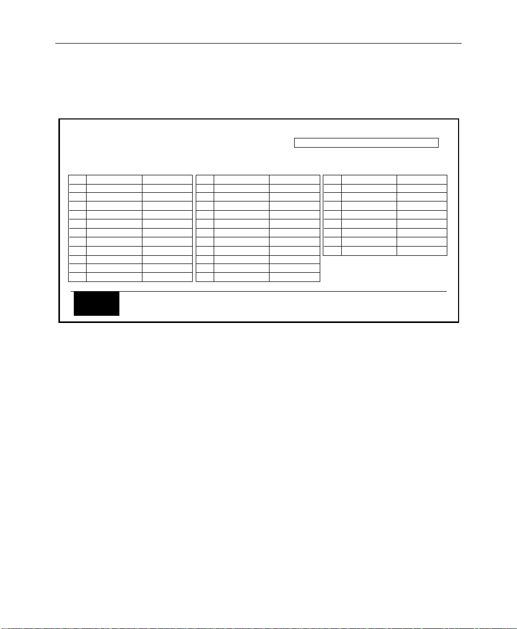
2. Press the INSTALL INFO> soft button to bring up the Main
Boards Menu:
INSTALLATION INFO MENU
status / install info
SLOT
1
-
2
-
3
-
4
-
-
5
-
-
MAIN
BOARDS
BOARD
M1 CK
DECODER
M2 CK
DECODER
M3 CK
DECODER
M1 KEYER
K1 BDL
K2 BDL
M2 KEYER
K1 BDL
K2 BDL
068907-01A
068943-228
068907-01A
068943-228
068907-01A
068943-228
068904-01D
068915-00A
068915-00A
068904-01D
068915-00A
068915-00A
UPPER
BOARDS
VERSION
SLOT
LOWER
BOARDS
6
-
7
8
9
10
11
12
-
This menu shows the functions of all the slots in the center card
cage (Bay B). Each slot that has a module installed indicates the
presence of the module by listing its assembly/version number.
(No assembly/version is shown for the Control Processor module
in cell 17 because it is unable to interrogate itself. However, you
can be sure that it is present and operating; otherwise you would
not have made it to this point.)
BOARD
M3 KEYER
K1 BDL
K2 BDL
SYNC
SAFE TITLE
XPT HI
XPT LO
FRAME STORE
DECODER
EFX SEND
M3 MIX/WIPE
PVW DIM
MODEL 3000-3 SOFTWARE VERSION: 5.0
VERSION
068904-01D
068915-00A
068915-00A
068901-00K
068917-00B
068900-00A
068900-00A
068911-00D
068903-08I
068942-00A
SLOT
13
M2 MIX/WIPE
-
14
M1 MIX/WIPE
15
16
PGM/PST/DSK
-
17
CTRL PROC
BOARD
PVW DIM
PVW DIM
SEC WIPE
K1 BDL
K2 BDL
VERSION
068903-08I
068942-00A
068903-08I
068942-00A
068912-00C
068905-00F
068915-00A
068915-00A
2-4
Entries that have a “-” in the left column are mezzanine boards
that might be installed on the modules listed immediately above
them in the table.
Note that the version of the installed software is displayed in the
upper right-hand corner of the display.
Page 41

3. Press the UPPER BOARDS soft button.
Powering Up
INSTALLATION INFO MENU
status / install info
SLOT
1
2
3
4
5
6
7
8
9
10
11
12
BOARD
RGB CK IN
RGB CK IN
RGB CK IN
DIG OUT-SER
ANLG OUT
DIG OUT-PAR
MAIN
BOARDS
068922-00C
068922-00C
068922-00C
068931-00F
068929-00F
068930-00C
UPPER
BOARDS
VERSION
SLOT
13
14
15
16
17
LOWER
BOARDS
This menu shows what slots in the upper card cage (Bay A) have
modules installed, and the format and assembly/version number
for each installed module.
You may wish to refer back to this menu when you are setting
parameters for analog and digital outputs and RGB chroma keyer
inputs.
BOARD
DIG OUT-PAR
ANLG OUT
MODEL 3000-3 SOFTWARE VERSION: 5.0
VERSION
068930-00C
068929-00F
2-5
Page 42

Section 2 — Startup & Configuration
4. Press the LOWER BOARDS button.
INSTALLATION INFO MENU
status / install info
SLOT
1
2
3
4
5
6
7
8
9
10
11
12
BOARDS
BOARD
DIG IN-PAR
DIG IN-PAR
DIG IN-SER
MAIN
068923-00B
068923-00B
068924-00C
UPPER
BOARDS
VERSION
LOWER
BOARDS
SLOT
13
14
15
16
17
This menu shows what slots in the lower card cage (Bay C) have
modules installed, and the format and assembly/version number
for each installed module.
You may wish to refer back to this menu when you are setting
parameters for analog and digital inputs.
BOARD
ANLG IN-AUTO
ANLG IN-AUTO
ANLG IN-AUTO
MODEL 3000-3 SOFTWARE VERSION: 5.0
VERSION
068921-00G
068921-00G
068921-00G
2-6
Page 43

Software Setup
The system parameters to be used at a particular site or in a
specific studio are usually configured immediately following
installation of the equipment. These include defining input
sources, assigning those sources to crosspoints, setting output
levels, and defining external interfaces. These operations are
accessed through the Configuration Menu, an overview of which
may be seen in the menu tree in Figure 2-1 and Figure 2-2.
The Configuration Menu
The Configuration Menu is a top-level menu that provides access
to the User Preferences, System Parameters, Inputs, Outputs,
External Interface, and Aux Bus Format submenus.
Software Setup
1. To begin the setup process, press the
Main Menu subpanel of the Upper Panel to display the
Configuration Menu.
CONFIGURATION MENU
config
USER
PREFS > INPUTS > OUTPUTS >
SYSTEM
PARAMS >
EXTERN
I/F >
AUX BUS
FORMAT >
CONFG button on the
2-7
Page 44

Section 2 — Startup & Configuration
CONFG
USER PREFS
SYSTEM PARAMS
INPUTS
OUTPUTS
EXTERN I/F
AUX BUS FORMAT
Software Version 5.3
See CONFIG Part 2
SHIFT MODE
KEYER PREFS
PREVIEW PREFS
BEEPER PREFS
DEFINE DEFAULTS
E-MEM PREFS
ASPECT RATIO
FIELD DOMINANCE
MATTE GEN LIM
H–BLANKING DEFAULT
INTERNAL BLK LV
SET CLOCK
START HORIZ BLANKING
END HORIZ BLANKING
SUPER BLACK OUTPUT
DIGITAL RES
EXT KEY SYNC
SETUP ON KEY
MAP INPUTS
CHR KEY INPUTS
GPI INPUTS
TOP TEST SIGNAL
BOTTOM TEST SIGNAL
3 M/E Switcher =
LATCH
NORMAL
DSK DROP
KEY MEMORY
CLEAR KEY MEM
PVW SELECT
PVW MODE
DIM PVW
PUSH TO PVW
BEEPER ON/OFF
WARNING
END OF KNOB
KNOB CENTER
INACTIVE KNOB
M/E SELECT
GVG DEFAULT
SET DEFAULT
RUN LEVER
KEYFRAME EDITING
MASTER E-MEM
4 X 3
16 X 9
FIELD 1
FIELD 2
NONE
GROUP SELECT
CARD SELECT
INPUT ...
INPUT ...
INPUT ...
INPUT ...
GROUP SELECT
CARD SELECT
INPUT ...
INPUT ...
INPUT ...
INPUT ...
VIDEO/KEY FMT
LOG/PHYS ASSIGN
NAME XPT BUTTON
VIDEO INPUT
KEY INPUT
CHROMA KEY INPUT
INPUT 1
INPUT 2
INPUT 3
INPUT 4
INPUT 5
INPUT 6
INPUT FORMAT
GPI SELECT
MISC
KF EFFECT
AUTO TRANS
CUT
E-MEM
FRAME STORE
PROGRAM GPI
XMITABLE
VALID RGB
BOTH
NONE
7.5 IRE
0 IRE
ON/OFF
M/E 1
M/E 2
M/E 3
PGM PST
ON
OFF
ON/OFF
ON/OFF
ON/OFF
ON/OFF
ON/OFF
M/E 1
M/E 2
M/E 3
ENABLE/DISABLE
ENABLE/DISABLE
300 STYLE
NORMAL
SELECT
CONFIRM
SECTION SELECT
BUS SELECT
CLEAR XPT
CLEAR BUS
CLEAR SECTION
CLEAR SWITCHER
AUTO
LOOKAHEAD
PGM
PUSH TO PVW TIMEOUT
1 TO 8
9 TO 16
Card ...
8 BIT
10 BIT
1 TO 8
9 TO 16
Card ...
NO SETUP
KEY SETUP
UNSHAPED VIDEO
SHAPED VIDEO
LOG CHANNEL
PHYS INPUTS
COARSE
FINE
RGB
BETA
YUV
GPI 1 — GPI 8
AUX TALLY
LOG CHAN TALLY
DISABLE GPI
VIDEO GRAB
KEY GRAB
MASK GRAB
ALL KEYERS
DELEG KEYER
OFF
DATE
TIME
GROUP SELECT
CARD SELECT
INPUT ...
INPUT ...
INPUT ...
INPUT ...
MANUAL TIME FOR INPUT ...
CURSOR BACK
ACCEPT CHAR
CURSOR FORWRD
DELETE CHAR
SAVE STRING
GET STRING
ACCEPT NAME
RUN
REWIND
AUTO RUN
REVERSE
YEAR
MONTH
DAY
HOUR
MINUTE
SECOND
M/E 1
M/E 2
M/E 3
DSK
AUX
MASK
A
B
KEY1
KEY2
1
2
3
4
5
6
7
1 TO 8
9 TO 16
Card ...
AUTOMATIC
MANUAL
DO SAVE
CANCEL
or
OVER WRITE
RENAME
CANCEL
M/E 1
M/E 2
M/E 3
PGM PST
DSK 1 TITLE
DSK 2 TITLE
PGM PST BLACK
M/E 1
M/E 2
M/E 3
PGM PST
DSK 1
DSK 2
M/E 1 RECALL
M/E 2 RECALL
M/E 3 RECALL
MSTR RECALL
AUTO RECALL
EFX DISSOLV
SEQUENCE
0754#1
2-8
Figure 2-1. Configuration Menu Tree, Part 1
Page 45

CONFG
See CONFIG Part 1
USER PREFS
SYSTEM PARAMS
INPUTS
OUTPUTS
EXTERN I/F
AUX BUS FORMAT
Software Version 5.3
OUTPUT SELECT
SUPER BLACK
SETUP ON KEY
VIDEO/KEY FMT
LIMITER
DIGITAL RES
OUTPUT TIMING
LUM CLIP
CHROMA CLIP
COMPOSITE CLIP
BLACK CLIP
EDITOR I/F
DPM I/F
PERIPH I/F
GPI OUTPUTS
AUX BUS 1B
AUX BUS 2B
AUX BUS 3B
AUX BUS 4B
AUX BUS 5B
AUX BUS 6B
AUX BUS 7B
3 M/E Switcher =
PGM
M/E 1 PGM
M/E 2 PGM
M/E 3 PGM
AUX BUS 1
AUX BUS 2
AUX BUS 3
AUX BUS 4
AUX BUS 5
AUX BUS 6
AUX BUS 7
FRAME STORE
ON
OFF
ON
OFF
SHAPED
UNSHAPED
ON
OFF
GROUP SELECT
CARD SELECT
M/E 1 PVW
M/E 2 PVW
M/E 3 PVW
DSK PVW
RESTORE DEFAULT
OUTPUT TIMING OFFSET
BAUD
PARITY
DEVICE SELECT
DPM TYPE
CHANNEL ROUTING
DPM MAP AUX BUS
DPM MAP INPUTS
EFF SEND DELAY
CONTROL DELAY
BAUD
PARITY
PERIPH TRIGGERS
PGM CUT TRIGGER
SELECT GPI
E-MEM LEVEL
GPI LENGTH
VIDEO
KEY
4 TO 10
11 TO 17
A ...
8 BIT
10 BIT
2400
4800
9600
19200
38400
ODD
EVEN
NONE
2400
4800
9600
19200
38400
ODD
EVEN
NONE
TRIGGER SELECT
FIRE ...
DEVICE NUMBER
FUNCTN NUMBER
OFF
GPI 1 — 8
1 — 8
MISC
DPM 1
DPM 2
DPM 3
DPM 4
DEVICE 1
DEVICE 2
DEVICE 3
DEVICE 4
KSCOPE
KRYSTAL
OTHER
NONE
SWR IN
SWR OUT
BOTH
OFF
DEVICE SELECT
NO. OF CHANNELS
CHAN 1 = AUX ...
DPM SELECT
CHANNEL SELECT
VIDEO INPUT
KEY INPUT
A
B
C
D
E
F
G
H
Software Setup
0754#2
MISC
PHYS CHAN
CHAN 1-8
DEVICE 1
AUX 1-7
DEVICE 2
DEVICE 3
DEVICE 4
DEVICE 1
DEVICE 2
DEVICE 3
DEVICE 4
CHAN A
CHAN B
CHAN C
CHAN D
CHAN E
CHAN F
CHAN G
CHAN H
SECONDARY
Figure 2-2. Configuration Menu Tree, Part 2
NOTE:
User Preferences will be addressed at the end of this section.
Refer to page 2-54.
2-9
Page 46

Section 2 — Startup & Configuration
Setting System Parameters
The System Parameters Menu allows you to set the video
standard (internal black level), to select the matte generator
chroma limiting algorithm, to adjust horizontal blanking and the
super black output level, and to set the system clock.
1. Press the SYSTEM PARAMS> soft button below the
Configuration Menu display to bring up the System
Parameters Menu:
SYSTEM PARAMETERS MENU
config / system params
XMITABLE
VALID RGB
BOTH
NONE
MATTE
GEN LIM
H-BLANKING
DEFAULT
2. With the INTERNAL BLACK LVL soft button, select either 7.5
IRE
or 0 IRE. This sets the video standard (internal black level)
for operation on the NTSC standard used in the U.S.A. (Black
= 7.5 IRE) or the NTSC standard used in Japan (Black = 0 IRE).
3. Set the START HORIZONTAL BLANKING soft knob as desired.
This adjusts the start of H blanking over a range of -16.0 clocks
to +16.0 clocks. The default value is 0.0 clocks.
7.5 IRE
0 IRE
INTERNAL
BLACK LVL
FIELD 1
FIELD 2
NONE
FIELD
DOM
START HORIZONTAL BLANKING
END HORIZONTAL BLANKING
SUPERBLACK OUTPUT
= 0.0 clocks
= 0.0 clocks
= -10.0 IRE
SET
CLOCK >
2-10
Page 47

Setting System Parameters
4. Set the END HORIZONTAL BLANKING soft knob as desired.
This adjusts the end of H blanking over a range of -16.0 clocks
to +16.0 clocks. The default value is 0.0 clocks.
Pressing the H-BLANKING DEFAULT button resets the
horizontal blanking start and end values to Grass Valley
default settings (0.0 clocks).
5. Set the SUPERBLACK OUTPUT LEVEL soft knob as desired.
This adjusts the super black output level over a range of -20.0
IRE to +7.5 IRE for U.S.A. NTSC, or -20.0 IRE to 0.0 IRE for the
Japanese NTSC.
6. Set the FIELD DOM to FIELD 1, FIELD 2, or NONE. Refer to
page 2-64.
7. Select the desired matte generator chroma limiting algorithm
with the MATTE GEN LIM button. The selections are as follows:
XMITABL — Prevents the total signal (luminance and
chrominance) from exceeding the NTSC transmission
standard.
VALID RGB — Limits colors to those which generate red,
green, and blue values within the 0 to 100% range.
BOTH — Selects a valid RGB color limiter that also
prevents the encoded signal envelope from exceeding
NTSC transmission level. (This is the system default
mode.)
NONE — Turns off all algorithm methods for matte
generator limiting.
8. The SET CLOCK> selection opens the Set Clock Menu, which
allows you to set the date and time for the system.
2-11
Page 48

Section 2 — Startup & Configuration
Setting the System Clock
1. From the System Parameters Menu, press the SET CLOCK>
soft button to display the Set Clock Menu.
SET CLOCK MENU
config / system param / set clock
July 4 1994
5:07:00 PM
Press "CONFIRM" button
to update the clock
DATE
TIME
SELECT CONFIRM
2. Set the date by selecting DATE with the SELECT button and
turning the soft knobs to select the appropriate YEAR, MONTH,
and DAY.
3. Press the CONFIRM button to enter the new date.
CLOCK
setting
YEAR
= 1994
MONTH
= July
DAY
= 4
2-12
Page 49
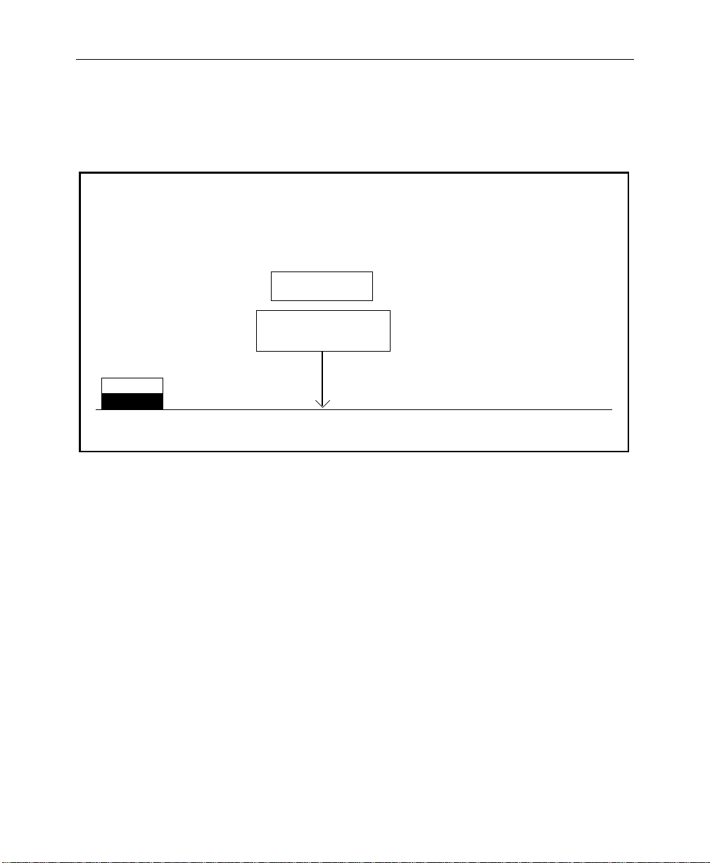
Setting System Parameters
4. Set the time by selecting TIME with the SELECT button and
using the soft knobs to select the HOUR, MINUTE, and
SECOND.
SET CLOCK MENU
config / system param / set clock
July 4 1994
5:07:00 PM
Press "CONFIRM" button
to update the clock
DATE
TIME
SELECT CONFIRM
5. Press the CONFIRM button to enter the new time.
6. Press the EXIT button to return to the Configuration Menu.
CLOCK
setting
HOUR
= 5 PM
MINUTE
= 7
SECOND
= 0
2-13
Page 50

Section 2 — Startup & Configuration
Configuring Inputs
Primary video and key inputs to the switcher are numbered 1
through 64. Each input can be treated as either a video signal or a
key signal.
Each input, including Black and Background, can be mapped to
any vertical column of source select (“crosspoint”) buttons.
Internally-generated sources (black, backgrounds, mask, etc.) are
also available for selection on the crosspoint matrix.
In the Model 3000-2, thirty-two inputs may be assigned to the
crosspoint buttons — 16 unshifted and 16 shifted inputs
(described below).
In the Model 3000-3, forty-eight inputs may be assigned to the
crosspoint buttons — 24 unshifted and 24 shifted inputs
(described below).
The external video and key assignments must correspond to the
video and key inputs connected to the frame, as described in the
Installation section of the Installation and Service manual.
2-14
The assignments made on the source selection panel may be any
combination of external inputs and internal inputs.
During the assignment procedure, each of the 32 (or 48) input
buses may be assigned a video signal, a key signal, and a chroma
key signal.
SHIFT button located at the right end of each primary source
The
selection row provides access to the 16 (or 24) shifted inputs.
Page 51
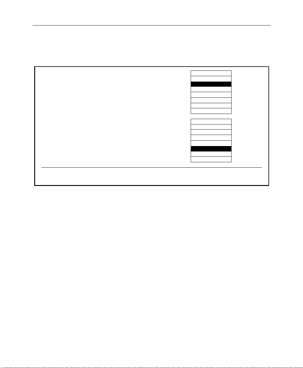
Configuring Inputs
From the Configuration Menu, press the INPUTS> button to bring
up the Inputs Menu.
INPUTS MENU
config / inputs
DIGITAL
RES >
EXT KEY
SYNC >
100% COLOR BARS
SETUP
ON KEY >
MAP
INPUTS >
CHR KEY
INPUTS >
75% COLOR BARS
MULTIBURST
MULTIPULSE
PULSE & BAR
CHR KEY TEST
H RAMP
H RAMP-LSB
100% COLOR BARS
75% COLOR BARS
MULTIBURST
MULTIPULSE
PULSE & BAR
CHR KEY TEST
H RAMP
H RAMP-LSB
GPI
INPUTS >
TEST SIGNAL
BOTTOM
TEST SIGNAL
The Inputs Menu allows you to enter or change the various
configuration settings for your inputs.
TOP
2-15
Page 52
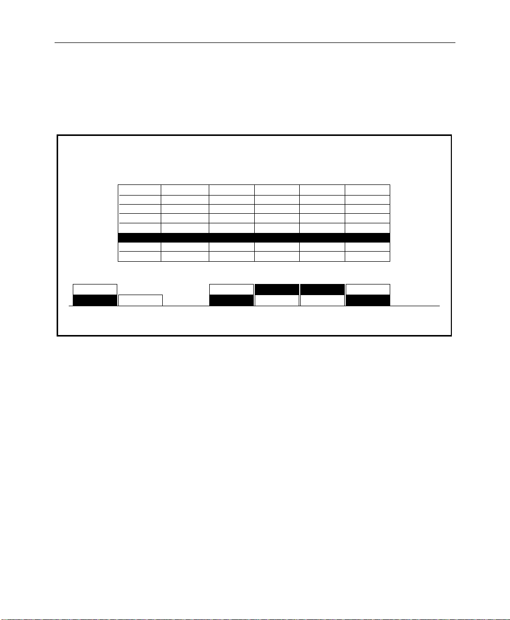
Section 2 — Startup & Configuration
Setting Input Digital Resolution
1. From the Inputs Menu, select DIGITAL RES> to display the
Input Digital Resolution Menu.
INPUT DIGITAL RESOLUTION MENU
config / inputs / digital res
1 TO 8
GROUP
SELECT
C9 33-36
C10 37-40
C11 41-44
C12 45-48
C13 49-52
C15 57-60
C16 61-64
C 149 TO 16
CARD
SELECT
SERIAL
ANALOG
ANALOG
SERIAL
PARALLEL
SERIAL 10 BITS 8 BITS 8 BITS 10 BITSC14 53-56
NO BOARD
SERIAL
10 BITS
-
-
10 BITS
8 BITS
-
10 BITS
8 BITS 8 BITS
INPUT
53
8 BITS
-
-
8 BITS
10 BITS
-
10 BITS
8 BITS 8 BITS
10 BITS10 BITS 10 BITS
INPUT
54
10 BITS
-
10 BITS
10 BITS
10 BITS
10 BITS
INPUT
55
10 BITS
-
8 BITS
8 BITS
8 BITS
INPUT
56
2. To set the digital resolution of a particular input, select the
group of input cards with the GROUP SELECT button. In the
example above, Input Module 14 (representing inputs 53
through 56) is selected.
Press the CARD SELECT button to select the desired input
module within the group previously selected. Note that the
analog input modules and any input module slots that have
“no board” are skipped as the CARD SELECT button is
pressed.
2-16
3. Set the input digital resolution to either 8-BIT or 10-BIT for
each of the four selected digital inputs.
4. Repeat steps 2 through 4 until all digital inputs have been
configured.
5. Press the EXIT button to return to the Inputs Menu.
Page 53
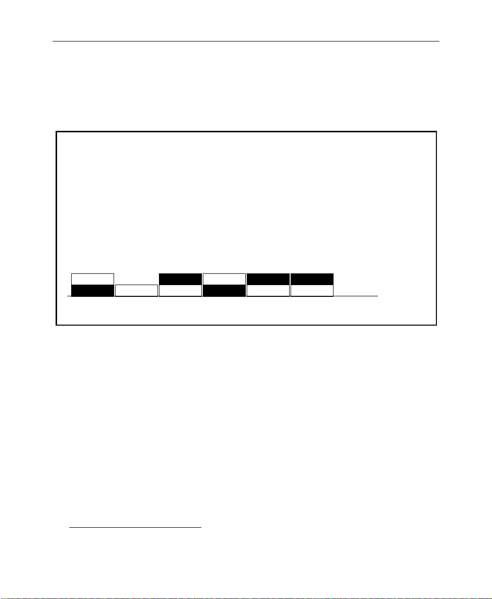
Configuring External Key Sync
1. From the Inputs Menu, press the EXT KEY SYNC> button to
select the External Key Sync Menu.
Configuring Inputs
EXT KEY SYNC MENU
config / inputs / ext key sync
1 TO 8
GROUP
SELECT
Card 149 TO 16 MANUAL
CARD
SELECT
AUTOMATIC AUTOMATIC AUTOMATICAUTOMATIC
INPUT
53
2. Use the GROUP SELECT and CARD SELECT buttons to select
the appropriate inputs.
3. Set the key sync to either AUTOMATIC or MANUAL for each of
the four selected digital inputs.
4. Note that a soft knob may be used to adjust the input timing
if the input module fails to detect sync. The range of the soft
knob is -256 clocks to +256 clocks1. The default setting is zero
(0) clocks.
INPUT
54
MANUAL MANUALMANUAL
INPUT
MANUAL TIME
FOR INPUT 53
= 0 clocks
MANUAL TIME
FOR INPUT 54
= 0 clocks
MANUAL TIME
FOR INPUT 55
= 0 clocks
MANUAL TIME
FOR INPUT 56
55
INPUT
56
= 0 clocks
5. Repeat steps 2 and 3 until all external key inputs have been
configured.
6. Press EXIT to return to the Inputs Menu.
1. A clock period is approximately 69.8 ns.
2-17
Page 54

Section 2 — Startup & Configuration
Configuring Key Setup
1. From the Inputs Menu, press SETUP ON KEY> to select the
Setup On Key Menu.
SETUP ON KEY MENU
config / inputs / setup on key
1 TO 8
GROUP
SELECT
CARD
SELECT
NO SETUP NO SETUP NO SETUP
KEY SETUP KEY SETUP KEY SETUP
INPUT
53
NO SETUP
KEY SETUPCard 149 TO 16
INPUT
54
INPUT
55
INPUT
56
2. Use the GROUP SELECT and CARD SELECT buttons to select
the appropriate inputs.
3. Set the setup to either NO SETUP or KEY SETUP for each of the
four selected inputs.
4. Repeat steps 2 and 3 until all key inputs have been configured.
5. Press the EXIT button to return to the Inputs Menu.
2-18
Page 55

Mapping Crosspoints
The Map Inputs Menu allows you to define the format for each
video or key input.
1. From the Inputs Menu, press the MAP INPUTS> button to
select the Map Inputs Menu.
Configuring Inputs
MAP INPUTS MENU
/config/inputs/map_inputs
UNSHAPED
VIDEO
SHAPED
VIDEO
VIDEO/
KEY FMT
Use the Preset Bus to select button number.
2. With the LOG/PHYS ASSIGNMENT button, select PHYS
NOTE:
button will be discussed later in this section under “Configuring a
DPM.”
XPT BUTTON
NUMBER
30
(SHIFT-14)
INPUTS
The
XPT BUTTON
NAME
.
LOG CHANNEL
function of the
VIDEO INPUT
(ANL AUT/10 BIT/SETUP)
(DIG SER/8 BIT/SETUP/SYNC)
CHROMA KEY INPUT
LOG CHANNEL
PHYS INPUTS
LOG/PHYS
ASSIGNMENT
NAME XPT
BUTTON >
= 4
KEY INPUT
= 1
= NONE
(ENCODED)
LOG/PHYS ASSIGNMENT
3. On the PST bus on the Source Select panel, press the
crosspoint button whose sources you wish to map. (All
crosspoints in that vertical column will have the same inputs.)
2-19
Page 56
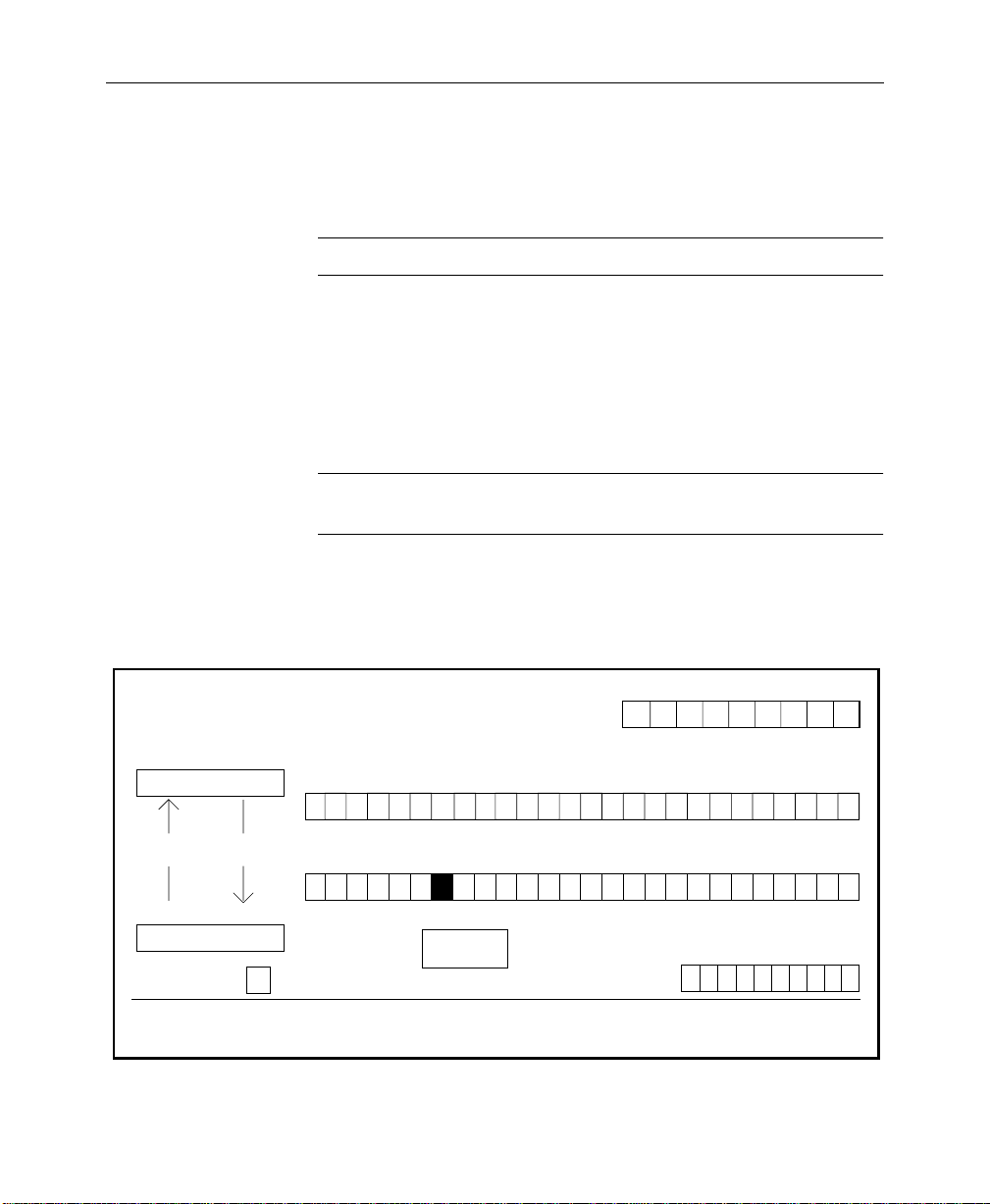
Section 2 — Startup & Configuration
4. Use the appropriate soft knob to select the desired type of
input. Note that input formats are displayed when selecting
input type.
NOTE:
Any crosspoint that is undefined defaults to black.
5. To map a chroma key input, use the CHROMA KEY INPUT soft
knob to assign the chroma key input for the currently selected
crosspoint button.
6. Use the VIDEO/KEY FMT button to assign whether the input
will use shaped video or unshaped video format.
NOTE:
This function is applied to a key input only if the external key
is being used with video or super black.
7. After mapping the input, you may name the crosspoint by
pressing NAME XPT BUTTON>. The Name Xpt Button Menu
then appears as shown below.
NAME XPT BUTTON MENU
config / inputs / map inputs / name xpt button
String Register:
Cam
a b c d e f g h i j k l m n o p q r s t u v w x y z
sp ' ( ) - / * : .
Button Name:
Cam 2 _
2-20
Save
String
Character = G
CURSOR
BACK
Get
String
ACCEPT
A B C D E F G H I J K L M N O P Q R S T U V W X Y Z
Use the Preset Bus to select button number.
CHAR
CURSOR
FORWARD
G
XPT BUTTON NUMBER
30
(SHIFT-14)
DELETE
CHAR
SAVE
STRING
1 2 3 4 5 6 7 8 9 0
GET
STRING
ACCEPT
NAME
Page 57

Configuring Inputs
8. Select each character by turning the soft knobs located to the
right of the Menu Display.
9. Enter the selected character by pressing the ACCEPT CHAR
button. The new character will be displayed in the menu.
10. Continue selecting characters in this manner until the desired
name is spelled out in the menu. You may enter up to 9
characters for the input name.
NOTE:
first 4 characters of the name will be displayed.
11. Press ACCEPT NAME to store the source name.
12. Repeat steps 3 through 11 until all inputs have been mapped
Press EXIT until the Inputs Menu reappears.
For a 3000-3 with the Input Readout Display option, only the
and named.
2-21
Page 58

Section 2 — Startup & Configuration
Formatting Chroma Key Inputs
1. From the Inputs Menu, press the CHR KEY INPUTS> button to
select the Chroma Key Inputs Menu:
CHROMA KEY INPUTS MENU
config / inputs / chr key inputs
INPUT
1
INPUT
2
INPUT
3
INPUT
2. In the Chroma Key Inputs Menu, select the appropriate
chroma key input and select the desired input format for that
input.
3. Adjust the coarse and fine timing for each chroma key input.
The range of the COARSE soft knob is -256 clocks to +256
clocks. Use the FINE soft knob to adjust the fractional value
from 0.000 to 0.999 clocks.
COARSE
TIMING = 0.000 clocks
FINE
RGB
BETA
YUV
4
INPUT
5
INPUT
6
INPUT
FORMAT
2-22
4. Press EXIT to return to the Inputs Menu.
Page 59

Assigning GPI Inputs
The GPI Inputs Menu allows you to configure GPI assignments
for signals that can be used to trigger Model 3000 functions. These
assignments must correspond to the physical GPI connections
described in the Installation section of the System Information
manual.
Eight GPI inputs are provided. All of these accept pulse-type GPI
inputs except Aux Tally Back, which is level-sensitive.
1. From the Inputs Menu, press the GPI INPUTS> button to select
the GPI Inputs Menu. (The first time you do this, no functions
will appear in the second column of the menu table.)
Configuring Inputs
GPI INPUTS MENU
config / inputs / gpi inputs
GPI 1
GPI 2
GPI 3
GPI 4
GPI 5
GPI 6
GPI 7
GPI 8
GPI 1
GPI
SELECT
MISC: AUX TALLY - 1
AT: FF
CUT: M/E 1
KF EFF: RUN
E-MEM: RCL MSTR - 26
DISABLE GPI
FRM STOR: VIDEO GRAB
E-MEM: RCL SEQ
MISC
When the desired function is selected,
press PROGRAM GPI button to set the
selected GPI input to the
selected function
Choose from these 6 buttons to select various
categories of GPI functions. Then use the
FUNCTION SELECT knob to select a function
KF
EFFECT
AUTO
TRANS E-MEMCUT
FUNCTION SELECT
AUX TALLY - 1?
FRAME
STORE
(MISC)
DISABLE GPIAUX TALLY
AUX BUS
MISC:
PROGRAM
GPI
= 1
2-23
Page 60

Section 2 — Startup & Configuration
The types of GPI assignments available are Miscellaneous
(Aux Tallies), Keyframe Effects, Auto Transitions, Cuts,
E-MEM registers, and Frame Stores, as indicated by the labels
under the bracket in the display. One of these functions is
always selected; the selected function is indicated in
parentheses under the FUNCTION SELECT knob label.
2. To assign a GPI input, first press GPI SELECT to select the
desired input.
3. Select the type of function to be assigned (Misc, Auto Trans,
etc.) by pressing the appropriate soft button.
4. Turn the FUNCTION SELECT knob to select the specific
function to be assigned (Aux Tally, etc.).
5. For each GPI, after the desired function has been selected,
press PROGRAM GPI to enter the selection. The function will
then appear in the table in the display.
The following functions are available for assignment:
2-24
MISC — Enables selection of the Aux Tally Back function, or
allows the selected GPI input to be disabled.
AUX TALLY — Allows an external device to control the
aux bus tally level (high or low). The AUX BUS soft knob
selects the appropriate aux bus.
DISABLE GPI — Causes any signal applied to the selected
GPI input to be ignored.
KF EFFECT — Enables selection of the Keyframe GPI function.
The following functions may be triggered with GPI pulses:
RUN, REWIND, AUTO RUN, and REVERSE
Page 61

Configuring Inputs
AUTO TRANS — Enables selection of the Auto Transition GPI
function. The following transitions may be triggered with GPI
pulses:
M/E 1, M/E 2, M/E 3, F-F, and F-F PST BLK
CUT
— Enables selection of the Cut GPI function. The
following cuts may be triggered by the GPI:
M/E 1, M/E 2, M/E 3, and F-F
E-MEM
— Enables selection of the E-MEM GPI function. The
following E-MEM functions may be triggered by the GPI:
RECALL M/E 1, RECALL M/E 2, RECALL M/E 3, RECALL
MSTR
, AUTO RECALL, EFX DISSOLV, and SEQUENCE. The
REGISTER
soft knob selects the register for E-MEM
recalls.
FRAME STORE — Enables selection of the Frame Store GPI
function. Triggered functions are as follows:
VIDEO GRAB, KEY GRAB, and MASK GRAB
2-25
Page 62

Section 2 — Startup & Configuration
Configuring Outputs
The signal formats of the Model 3000 output modules for your
installation are set up from the Outputs Menu.
1. Press the CONFG button on the main menu subpanel.
2. From the Configuration Menu, select OUTPUTS> to display
the Outputs Menu.
OUTPUTS MENU
config / outputs
PGM OFF ONSHAPEDOFF
M/E 1 PGM
M/E 2 PGM
M/E 3 PGM
AUX BUS 1
AUX BUS 2
AUX BUS 3
AUX BUS 4
AUX BUS 5
AUX BUS 6
AUX BUS 7
FRAMESTORE
PGM
OUTPUT
SELECT
ON
ON
OFF
OFF
OFF
OFF
OFF
OFF
OFF
OFF
OFF
ON
OFF
SUPER
BLACK
LUM CLIP
= 105 IRE
OFF
-
-
-
-
-
-
-
-
-
-
-
OUTPUT
TIMING >LIMITER
DIGITAL
RES >
CHROMA CLIP
= 105 %
COMPOSITE CLIP
= 138 IRE
BLACK CLIP
= -20 IRE
ON
OFF
OFF
OFF
OFF
OFF
OFF
OFF
OFF
OFF
OFF
ON ON
OFF
SETUP
ON KEY
-
-
SHAPED
SHAPED
SHAPED
UNSHAPED
-
-
-
-
SHAPED
UNSHAPED
VIDEO/KEY
FMT
3. Select the output to change from the default setting by
pressing the OUTPUT SELECT button.
4. Set the characteristics of the selected output, as follows:
SUPERBLACK — T urns the superblack output ON or OFF. (The
Superblack output level is set in the System Parameters Menu,
as described previously.)
2-26
Refer to the Super Black Application Note in the Appendices
section of this manual for information on using Super Black.
SETUP ON KEY — Selects or deselects setup on the key output
signal.
Page 63

Configuring Outputs
NOTE:
The
VIDEO/KEY FMT
selections apply only to the Program
output and Aux Bus 1-through 4 signals.
UNSHAPER — Sets the output processing to provide the type
of signal desired by the external device: ON if the video is
already shaped but the external device needs a full screensized picture; OFF if the device can accept video that has
already been processed by a key signal.
NOTE:
The
LIMITER
selections apply only to the Program output
signal.
LIMITER — T urns the output limiter on or off. The ON selection
allows adjustment of the Program Output characteristics, as
defined by the soft knob settings. Note that the soft knobs are
functional only when
LIMITER is ON.
Use the LUM CLIP soft knob to adjust the luminance
clipping level of the output signal. This clips out
luminance levels above the selected threshold. The range
of the soft knob is from 75 IRE to 138 IRE. The default
setting is 105 IRE.
Use the CHROMA CLIP soft knob to adjust the
chrominance clipping level of the output signal. This clips
out chrominance levels above the selected threshold. The
range of the soft knob is from 80% to 120%. The default
setting is 105%.
Use the COMPOSITE CLIP soft knob to adjust the
composite clipping level of the output signal. This clips
out chrominance and luminance levels above the selected
threshold. The range of the soft knob is from 75 IRE to 138
IRE. The default setting is 138 IRE.
Use the BLACK CLIP soft knob to adjust the black clipping
level of the output signal. This clips out luminance levels
below the selected threshold. The range of the soft knob is
from -20 IRE to 0 IRE. The default setting is -20 IRE.
DIGITAL RES> — Displays the Output Digital Resolution
Menu.
2-27
Page 64

Section 2 — Startup & Configuration
Setting Switcher Output Timing
With the Effects Send option installed in a Model 3000, the PGM
output on Aux Buses 1 through 4 was delayed compar ed to other
switcher outputs. Software provides an adjustment of the
switcher length that allows you to match the timing of all outputs.
CA UTION
Adjustment of the switcher output timing is not recommended
unless you have the Effects Send option and you expect to use
PGM out on Aux Buses 1 through 4.
Increasing the switcher length may affect other timing in your
facility.
The switcher length timing adjustment is done in the
Configuration/Outputs/Output Timing menu.
1. To gain access to the switcher length adjustment, first press
the CONFG button on the main menu subpanel, then press the
OUTPUTS> soft button in the Configuration menu.
OUTPUTS MENU
config / outputs
PGM OFF ONONOFF
M/E 1 PGM
M/E 2 PGM
AUX BUS 1
AUX BUS 2
AUX BUS 3
AUX BUS 4
AUX BUS 5
AUX BUS 6
AUX BUS 7
FRAMESTORE
PGM
OUTPUT
SELECT
2-28
ON
ON
OFF
OFF
OFF
OFF
OFF
OFF
OFF
OFF
ON
SUPER
BLACK
ON
OFF
OFF
OFF
OFF
OFF
OFF
OFF
OFF
OFF
ON ON
SETUP
ON KEY UNSHAPER LIMITER
-
-
ON
OFF
OFF
OFF
-
-
-
-
ON
OFFOFF OFFOFF
-
-
-
-
-
-
-
-
-
-
DIGITAL
RES >
LUM CLIP
= 105 IRE
CHROMA CLIP
= 105 %
COMPOSITE CLIP
= 138 IRE
BLACK CLIP
= -20 IRE
OUTPUT
TIMING >
Page 65

Configuring Outputs
2. Press the
Timing menu.
OUTPUT TIMING MENU
config / outputs / output timing
Adjustment of the Output Timing Offset knob will change
reference and electrical path length of the switcher.
The OUTPUT TIMING OFFSET knob allows you to increase the
overall switcher length by from 1 to 255 clocks.1 Default
timing is 0 clocks.
OUTPUT TIMING
WARNING
soft button to bring up the Output
OUTPUT TIMING OFFSET
= 0 clocks
(00.00 nsecs)
RESTORE
DEFAULT
3. Adjust the OUTPUT TIMING OFFSET knob as required to make
the video look best under your operating conditions.
For viewing the switcher PGM Out signal on the Aux 1
through Aux 4 outputs, the adjustment should typically be set
for 11 clocks (768.25 ns).
For viewing video through the longest path through the
switcher (PGM Out on Mask Bus and Mask Bus out on PVW
bus), the adjustment should typically be set for 49 clocks
(3422.15 ns).
1. A clock is equal to approximately 69.84 ns.
2-29
Page 66

Section 2 — Startup & Configuration
Setting Output Digital Resolution
1. From the Outputs Menu, press the DIGITAL RES> button to
bring up the Output Digital Resolution Menu.
OUTPUT DIGITAL RESOLUTION MENU
config / outputs / digital res
4 TO 10
11 TO 17
GROUP
SELECT
A 11
A 12
A 13
A 14
A 15
A 16 PARALLEL 8 BITS8 BITS10 BITS 8 BITS
A 17
CARD
SELECT
SERIAL
ANALOG
PARALLEL
SERIAL
NO BOARD
ANALOG
10 BITS
-
8 BITS
10 BITS
-
-
8 BITS
10 BITS
8 BITS
-
8 BITS
10 BITS
-
-
8 BITS
10 BITSA 16
SWITCHED
PVWMASK
10 BITS
8 BITS
8 BITS
-
-
8 BITS 8 BITS
10 BITS
DSK PGM
VIDEO
10 BITS
10 BITS
DSK PGM
This menu allows you to set each digital output to 8- or 10-bit
resolution.
8 BITS
8 BITS
-
-
KEY
2-30
Page 67

Configuring Outputs
2. Use the GROUP SELECT and CARD SELECT buttons to select
the appropriate outputs.
Note that as the output boards are selected with CARD
SELECT
buttons.
3. Set the resolution to either 8-BIT or 10-BIT for each of the four
selected digital outputs.
4. Repeat steps 2 and 3 until all digital outputs have been
configured.
, the names of the outputs change above the soft
NOTE:
Process Menu.
5. Press the main menu CONFG button to return to the
Dithering of the 8-bit outputs is selectable in the Misc/Signal
Configuration Menu.
2-31
Page 68

Section 2 — Startup & Configuration
Configuring External Interfaces
Most parameters for external interfaces can be set up or changed
through the External Interface Menu.
1. From the Configuration Menu, select EXTERN I/F> to display
the External Interface Menu. This menu provides selections
for defining interface parameters for peripherals connected to
the Model 3000.
EXTERNAL INTERFACE MENU
config / extern if
2-32
EDITOR
I/F >
DPM
I/F >
PERIPHERAL
I/F >
GPI
I/F >
Page 69
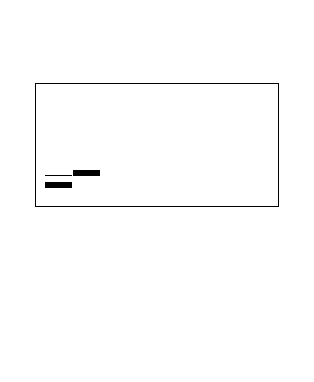
Setting Editor Port Parameters
1. From the External Interface Menu, press EDITOR I/F> to select
the Editor Interface Menu.
EDITOR INTERFACE MENU
config / extern if / editor if
2400
4800
9600
19200
38400
ODD
EVEN
NONE
PARITYBAUD
Configuring External Interfaces
2. With the BAUD and PARITY buttons, select the baud rate and
parity parameters for the editor port by incrementing to the
desired settings.
3. Press EXIT to return to the External Interface Menu
2-33
Page 70

Section 2 — Startup & Configuration
Configuring a DPM
Digital Picture Manipulators (DPMs) are external video devices
connected to the switcher. In this discussion, reference is also
made to DPM levels, which are E-MEM levels into which DPMassociated information is learned. The combined system
capabilities of the switcher and DPMs depend on:
■ The video connection
■ The capabilities of the DPM
■ The control connection
It is not necessary to have a control connection from the switcher
to a DPM; however, the highest level of system integration is
achieved where there is a control connection.
Video Connection (Aux Buses and Return Inputs)
A normal video signal path consists of an aux bus output fr om the
switcher feeding a DPM input and the DPM output returned to a
switcher input which is mapped to a switcher source select
button.
2-34
The video path through a DPM introduces a video delay into the
system. For example, Kaleidoscope introduces a 2-field video
delay. It is most important that this delay be set correctly in the
DPM Setup Menu if Effects Send is to be used.
NOTE:
If the video delay is not set correctly, ther e will be a glitch in the
video upon entering Effects Send mode.
Page 71

Configuring External Interfaces
There are four steps in configuring the video path:
■ Aux buses are assigned to DPMs using the DPM Map Aux
Buses Menu
■ Return input connections are configured using the DPM Map
Inputs Menu
■ The mapping of a return connection to a crosspoint is done
using the Configuration/Map Inputs Menu
■ The video delay is set using the DPM Setup Menu.
The system defaults to all aux buses being part of the MISC
E-MEM level. When an aux bus is configured for use with an
external DPM, its settings are no longer saved in the MISC level
but are saved in the relevant DPM level when an E-MEM register
is learned. Information (such as aux bus crosspoint selection) is
learned for each DPM on separate
E-MEM levels.
In cases where it is not desirable to have an aux bus selection
learned/recalled on the MISC level, it is possible to configure the
aux bus to a DPM level (such as DPM 4) and never enable that level.
An example would be if the aux bus were controlled by a Remote
Aux panel.
DPM Capabilities (Fixed and Pooled)
The characteristics of the DPM are configured in the DPM Setup
Menu. The first choice to be made is selection of DPM TYPE from
KSCOPE, KRYSTAL, OTHER FIXED or NONE.
The DPM TYPE of NONE indicates that there is no external DPM
device used for the particular DPM level. However , it can also be
used for cases where aux buses are assigned to a DPM level, but
there is no physical device, no return signal, and no control
connection (for example, an aux bus dedicated to feeding a video
monitor).
2-35
Page 72

Section 2 — Startup & Configuration
Both KSCOPE and KRYSTAL are selections for pooled devices.
A pooled device is one which provides acquisition of logical
channels from a pool of physical channels.
Kaleidoscope is a pooled device. As an example, consider a
Kaleidoscope having 5 physical channels named A, B, C, D,
and E. The pooled channels are shared by different users. A
user may build a Kaleidoscope effect using 3 channels. On one
day he may acquire physical channels C, D, and E as logical
channels 1, 2, and 3; on another day he may acquire physical
channels B, C, and D as logical channels 1, 2, and 3. The same
effect will perform identically on both configurations since
the operator’s view of the system is the logical arrangement of
channels (1, 2, 3), not the physical channels used.
In systems with multiple DPM channels, it is desirable to have a
predictable relationship between aux buses and DPM channels
(e.g., aux bus 1 feeding DPM channel 1, aux bus feeding channel
2, etc.) and to have a particular switcher crosspoint button always
select the same DPM channel return input. For a fixed device
(such as the DPM-700) this relationship is achieved by cabling
alone. For a pooled device, such as Kaleidoscope, the Model 3000
achieves predictable DPM channel routing by maintaining an
extra level of mapping between physical and logical DPM
channels. This mapping, termed Switcher Input Routing and
Switcher Output Routing, is discussed on the following page.
2-36
DPM TYPEs of OTHER FIXED or NONE (DPMs which are not
For
pooled and do not have Input and Output Routing), the CHANNEL
ROUTING
Kaleidoscope changes its logical-to-physical channel mapping,
depending on the order in which channels are acquired from its
pool. Switcher output routing maps a physical aux bus to a logical
aux bus so that the logical aux bus number corresponds with the
DPM’s logical channel.
selection should be OFF.
Page 73
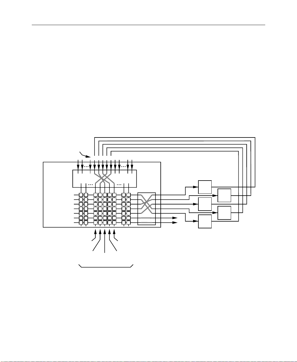
Model 3000
Kaleidoscope
Physical
Channels
Configuring External Interfaces
The Aux Bus button selection made on the switcher control panel
is always a logical aux bus; however, unless Kaleidoscope is
connected, Logical Aux Bus 1 always corresponds to Physical Aux
Bus 1, etc. (The current mapping of physical-to-logical DPM
channels is displayed in the DPM Map Inputs Menu.)
It should be noted that the switcher supports only one pooled
device. In the example in Figure 2-3, Physical Aux Bus 1 is
connected to Kaleidoscope Physical Channel A, Bus 2 to
Channel B, and so on.
0347-02-29
EDCBA
Switcher
Input
Routing
Logical Aux 1
Logical Aux 2
Logical Aux 3
Logical Aux 4
Logical Aux 5
Logical Aux 6
Logical Aux 7
Kaleidoscope
Channel Pool
A
C
E
Logical
Channel
1
Logical
Channel
2
Kaleidoscope
Logical Channels
Logical
Channel
3
Logical
Channel
Logical
Channel
4
Switcher
Output
Routing
5
Phys Aux 1
Phys Aux 2
Phys Aux 3
Phys Aux 4
Phys Aux 5
Figure 2-3. Example of Connections for a Pooled DPM
B
D
2-37
Page 74

Section 2 — Startup & Configuration
For a particular studio session, three Kaleidoscope channels could
be acquired from the pool in the order D, E, A, which would be
logical channels 1, 2, 3. This mapping information is passed from
the DPM to the switcher via the control connection. Switcher
output routing ensures that the logical channels 1, 2, 3 appear to
the user on logical aux buses 1, 2, 3 and switcher input routing
ensures that DPM logical channels 1, 2, 3 appear on the
crosspoints configured for these logical channels. For the above
configuration, the selection of CHANNEL ROUTING in the DPM
Setup Menu should be set to BOTH.
There are circumstances wher e output routing is not desirable. For
example, the DPM may have more than 5 channels. In that case, a
router or patch panel may be inserted between the switcher and
Kaleidoscope (Figure 2-4). In this example, switcher output
routing is turned off, so the menu selection for
ROUTING
still provides the return video from the switcher being on a
consistent crosspoint.
in the DPM Setup Menu should be set to SWR IN. This
CHANNEL
2-38
Page 75

16 Inputs
Model 3000
Switcher
Input
Routing
Aux 1
Aux 2
Aux 3
Aux 4
Aux 5
Aux 6
Aux 7
Logical
Channel
1
Logical
Channel
2
Kaleidoscope
Logical Channels
Logical
Channel
3
HGFEDCBA
Logical
Channel
Logical
Channel
4
5
Patch Panel
Aux Bus Outputs
From Other Suites
Configuring External Interfaces
Router/
Kaleidoscope
Channel Pool
A
B
C
D
E
F
G
H
To Other Suites
0347-02-30
Figure 2-4. Example of Connections Using an External Router
2-39
Page 76

Section 2 — Startup & Configuration
Control Connections
Three forms of control connection to the DPMs are supported.
These are:
■ CPL (Control Point Language)
■ PBusII (Peripheral Bus II)
■ GPIs
Control Point Language — CPL is the communication protocol used
to couple the switcher with Kaleidoscope or Krystal. One of its
uses is to convey the physical-to-logical channel mapping
information described previously. It is also used for run control of
effects, aux bus selection (including front/back switching) and
tally.
DPM TYPE is set to KSCOPE in the DPM Setup Menu, CPL
When
is automatically invoked. PORT ASSIGN must be set to the port to
which the serial cable is connected (PORT A1).
Also, when KSCOPE is selected as the DPM TYPE, aux bus control
is automatically assigned to Kaleidoscope. With Kaleidoscope
controlling the aux buses, when a source button is selected on the
Kaleidoscope panel, that source button is also selected on the
switcher for that aux bus, and vice versa. So an effect running on
Kaleidoscope can cause the switcher to select different
crosspoints. This is the mechanism used to achieve front/back
switching.
2-40
All control connections have an associated control delay. The
CONTROL DELAY in the DPM Setup Menu should be set to 6 fields
when the DPM TYPE is set to KSCOPE.
When any other type of DPM is selected as the DPM TYPE, aux bus
control is performed by the Model 3000 Switcher.
Peripheral Bus II (Port A3 Only) — PBusII is used for run control of
effects using triggers. With current software, PBusII triggers are
learned into the MISC E-MEM level. For example, when using
PBusII as the control connection for a DPM-700, the following
should be set in the DPM Setup Menu:
Page 77

Configuring External Interfaces
PORT ASSIGN = NONE
CHANNEL ROUTING
GPIs — Both input and output GPIs may be used as triggers as part
of the control interface between the DPM and switcher.
Depending on the nature of the DPM, GPIs can be used for effect
recall and run control, source selection, and tally information.
Configuring the DPM Interface
Set up the DPM type, video delay, control delay, port assignment,
and channel routing for each of (up to) 4 DPM devices as follows:
1. From the External Interface Menu, press DPM I/F> to bring up
the DPM Setup Menu.
= OFF
DPM SETUP MENU
config / extern if / dpm setup
EFF SEND
DEVICE 1 2PORT A1 DPM 17
DEVICE 2
DEVICE 3
DEVICE 4
DPM1
DEVICE
SELECT
DEVOUS
OTHER FIXED
NONE
NONE
KSCOPE
KRYSTAL
DVEOUS
OTHER FIXED
NONE
DPM
TYPE
NONE
NONE
NONE
CHANNEL
ROUTING
2. From the DPM Setup Menu, press DEVICE SELECT to select
the desired DEVICE (1 through 4).
DELAY
–
–
–
CONTROL
DELAY
0
0
0
E-MEM LEVELS
DPM 2
DPM 3
DPM 4
DPM MAP
AUX BUSES >
EFF SEND DELAY
= 2 fields
CONTROL DELAY
= 7 fields
DPM MAP
INPUTS >
3/4000 v5.3
2-41
Page 78

Section 2 — Startup & Configuration
For Kaleidoscope
a. Set the DPM TYPE in the 3000 DPM Setup Menu to
KSCOPE.
NOTE:
delay allows a new DPM TYPE to be chosen without cycling through
intermediate DPM Types. Once the desired solution has been made, the
new DPM TYPE will be set 2 seconds later.
A delay has been introduced when changing DPM TYPE. This
b. T urn the EFF SEND DELAY soft knob to select 2 fields. It is
important that this delay be set correctly.
c. Turn the CONTROL DELAY knob to select 6 fields.
d. Set CHANNEL ROUTING, for SWR IN or BOTH, depending
upon your system configuration, as described previously
under “Configuring a DPM.”
e. Reset the Control Processor in the Model 3000 Signal
Processor frame. This is done by opening the front door of
the Processor and pressing the RESET button located near
the top of the Control Processor module in cell 17 of Bay B.
Communication should now be established between the
Model 3000 and Kaleidoscope.
For a DPM-700
a. Set the DPM TYPE, to OTHER FIXED.
2-42
b. T urn the EFF SEND DELAY soft knob to select 2 fields. It is
important that this delay be set correctly.
(The CONTROLDELAY softknob has no effect with the
DPM-700.)
c. Set PORT ASSIGN to NONE.
d. Set CHANNEL ROUTING, to OFF.
Page 79

Configuring External Interfaces
For DVEous:
a. Set the DPM TYPE to DVEOUS.
b. Turn the VIDEO DELAY soft knob to select 2 FIELDS. It is
important to set this delay correctly.
c. Turn the CONTROL DELAY soft knob to select 7 FIELDS.
d. Press the PORT ASSIGN button to assign PORT A1 to the
DPM. The baud rate for Port A1 is fixed at 307 K baud.
e. Set CHANNEL ROUTING for BOTH or SWR IN, depending
upon your system configuration, as described previously
under “DPM Configurations.”
f. Reset the Control Processor in the Model 4000 Signal
Processor frame. This is done by opening the front door of
the Processor and pressing the RESET button located
near the top of the Control Processor module.
For Other Non-Poolable DPMs
For devices which must be set up manually:
1. Program all other required parameters
2. Set EFF SEND DELAY to 0
3. Select BLACK on the Aux Bus feeding the external device
NOTE:
delay allows a new DPM TYPE to be chosen without cycling through
intermediate DPM Types. Once the desired solution has been made, the
new DPM TYPE will be set 2 seconds later.
4. Turn the Effects Send On and Off and look for a flash of the
5. Increase the EFF SEND DELAY one field at a time until there is
A delay has been introduced when changing DPM TYPE. This
wrong video (BLACK) as Effects Send is turned on. (The flash
appears on the M/E output for the Effects Send you selected.)
no video flash when turning on Effects Send.
2-43
Page 80
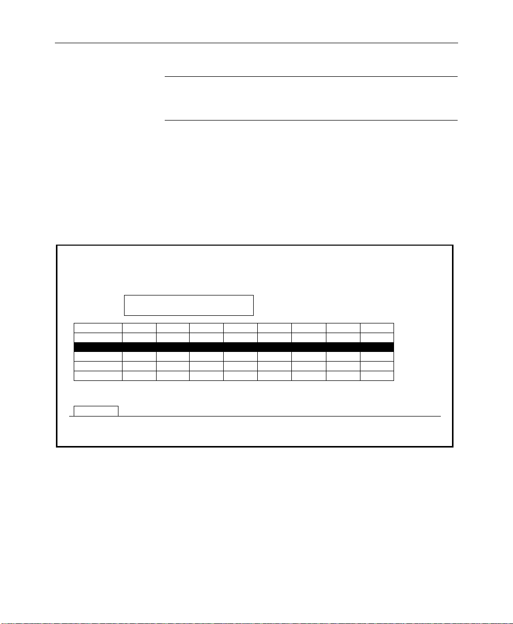
Section 2 — Startup & Configuration
NOTE:
Increasing the EFF SEND DELA Y any further will not change
the Effects Send appearance. It will, however , delay the entry into Effects
Send unnecessarily.
Mapping DPM Aux Buses
Set up the aux bus-to-device assignment as follows:
1. From the DPM Setup Menu, press DPM MAP AUX BUSES> to
access the DPM Map Aux Buses Menu.
DPM MAP AUX BUSES MENU
config / extern if / dpm setup / dpm map aux buses
Connection of physical AUX buses
to physical channels
MISC
PHYS CHAN
DPM 1 - - - - AUX3 AUX 4AUX 2AUX 1
DPM 2
DPM 3
DPM 4
AUX 5
CHAN A
AUX 6
CHAN B
-
-
-
AUX 7
CHAN C
-
-
-
-
-
-
-
CHAN D
-
-
-
-
CHAN E
-
-
-
-
CHAN F
-
-
-
-
CHAN G
-
-
-
NUMBER OF CHANNELS
FIRST CHANNEL
-
CHAN H
-
-
-
= 4
= CHAN E
2-44
DPM 1
DEVICE
SELECT
2. Press the DEVICE SELECT button to select the desired DEVICE
(1 through 4).
3. For Kaleidoscope, rotate the NUMBER OF CHANNELS knob to
assign Aux Buses 1 through n to this DPM number. Turn the
FIRST CHANNEL knob to assign the first aux bus to the first
physical channel of the DPM.
Page 81

Configuring External Interfaces
NOTE:
All aux buses assigned to a DPM must be in consecutive order .
4. For a DPM-700, set the NUMBER OF CHANNELS and
CHANNEL 1 = soft knobs as appropriate for your installation.
NOTE:
Assigning an Aux Bus to a DPM level saves the parameters
under the DPM level, rather than the MISC level for E-MEM
operations.
5. Press the EXIT button to return to the DPM Setup Menu.
Mapping DPM Inputs
Set up the DPM video and key return input numbers as follows:
1. From the DPM Setup Menu, press DPM MAP INPUTS> to bring
up the DPM Map Inputs Menu.
DPM MAP INPUTS MENU
config/extern if/dpm setup/dpm map inputs
VIDEO INPUT
DEVICE 1
(DEVOUS)
DEVICE 1
DEVICE 2
DEVICE 3
DEVICE 4
DPM
SELECT
CHAN 1
CHAN 2
CHAN 3
CHAN 4
CHAN 5
CHAN 6
CHAN 7
SECONDARY
CHAN 2
CHANNEL
SELECT
LOGICALPHYSICAL
KEY INPUT
–
19 42
29
–
–
–
–
–
VIDEO INPUT
= 19
–
KEY INPUT
63
–
–
–
–
–
= 42
V5.3
2-45
Page 82

Section 2 — Startup & Configuration
2. Press the DPM SELECT button to select the desired DEVICE
(1 through 4).
3. Press the CHANNEL SELECT button to select the desired
DEVICE channel.
4. Turn the VIDEO INPUT knob to assign the Model 3000 physical
input 1 to 64 to which this DPM video return was connected
during cabling.
5. Turn the KEY INPUT knob to assign the Model 3000 physical
input 1 to 64 to which this DPM key return was connected
during cabling.
6. Set up the aux bus format using the Aux Bus Format Menu, as
described later in this section. Make sure that any aux buses
assigned to Kaleidoscope are configured for
their B aux buses.
KEY operation of
NOTE:
are to be used for Effects Send. When Effects Send is selected, the B bus
of each selected aux bus is automatically configured as a key.
Mapping DPM Returns
Complete the DPM Setup by assigning the DPM channel returns
to Model 3000 crosspoints as follows:
1. Bring up the Map Inputs Menu by pressing the following
buttons:
CONFG, INPUTS>, MAP INPUTS>
2. Press a crosspoint button on the Preset bus to select the
crosspoint whose input mapping is to be changed.
3. Select LOG CHANNEL with the LOG/PHYS ASSIGNMENT
button.
4. Rotate the VIDEO INPUT knob to assign the desired DPM
number and logical channel for this crosspoint. For example,
It is not necessary to set the video/key format for aux buses that
2-46
Page 83
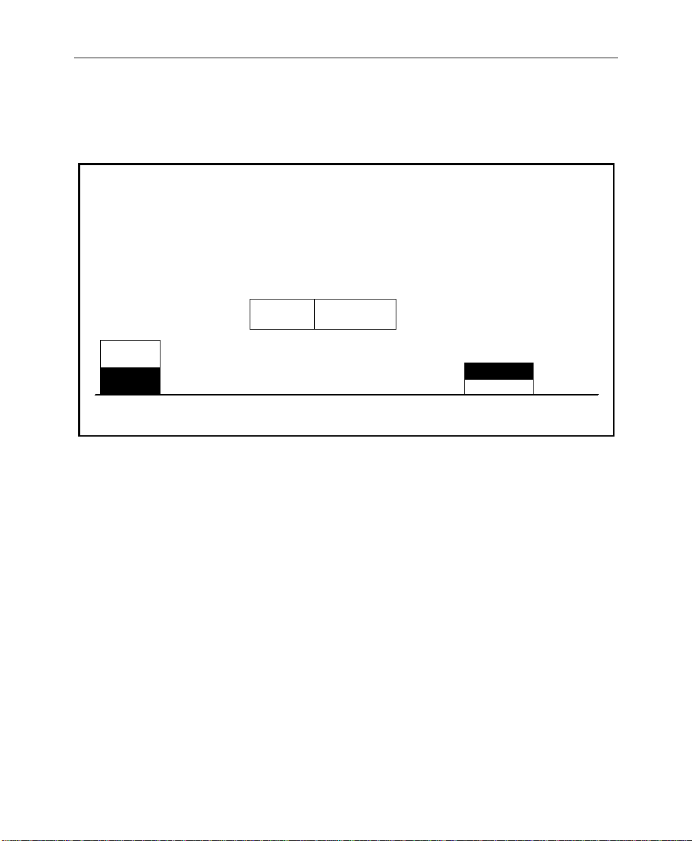
Configuring External Interfaces
assign logical channel 1 of DPM 1 by selecting DPM 1
LOG CHAN 1
.
MAP INPUTS MENU
config / inputs / map inputs
UNSHAPED
VIDEO
SHAPED
VIDEO
VIDEO/
KEY FMT
Use the Preset Bus to select button number.
5. Rotate the KEY INPUT knob to assign the desired DPM
6. Rotate the CHROMA KEY INPUT knob to select the chroma key
VIDEO INPUT
XPT BUTTON
NUMBER
12
XPT BUTTON
NAME
= DPM 1 LOG CHAN 1
= DPM 1 LOG CHAN 1
CHROMA KEY INPUT
LOG CHANNEL
PHYS INPUTS
LOG/PHYS
ASSIGNMENT
(KSCOPE)
KEY INPUT
(KSCOPE)
= NONE
(ENCODED)
NAME XPT
BUTTON >
number and logical channel for this crosspoint. For example,
assign logical channel 1 of DPM 1 by selecting DPM 1 LOG
CHAN 1.
input for this crosspoint.
7. Press the main menu CONFG button to return to the
Configuration Menu.
2-47
Page 84
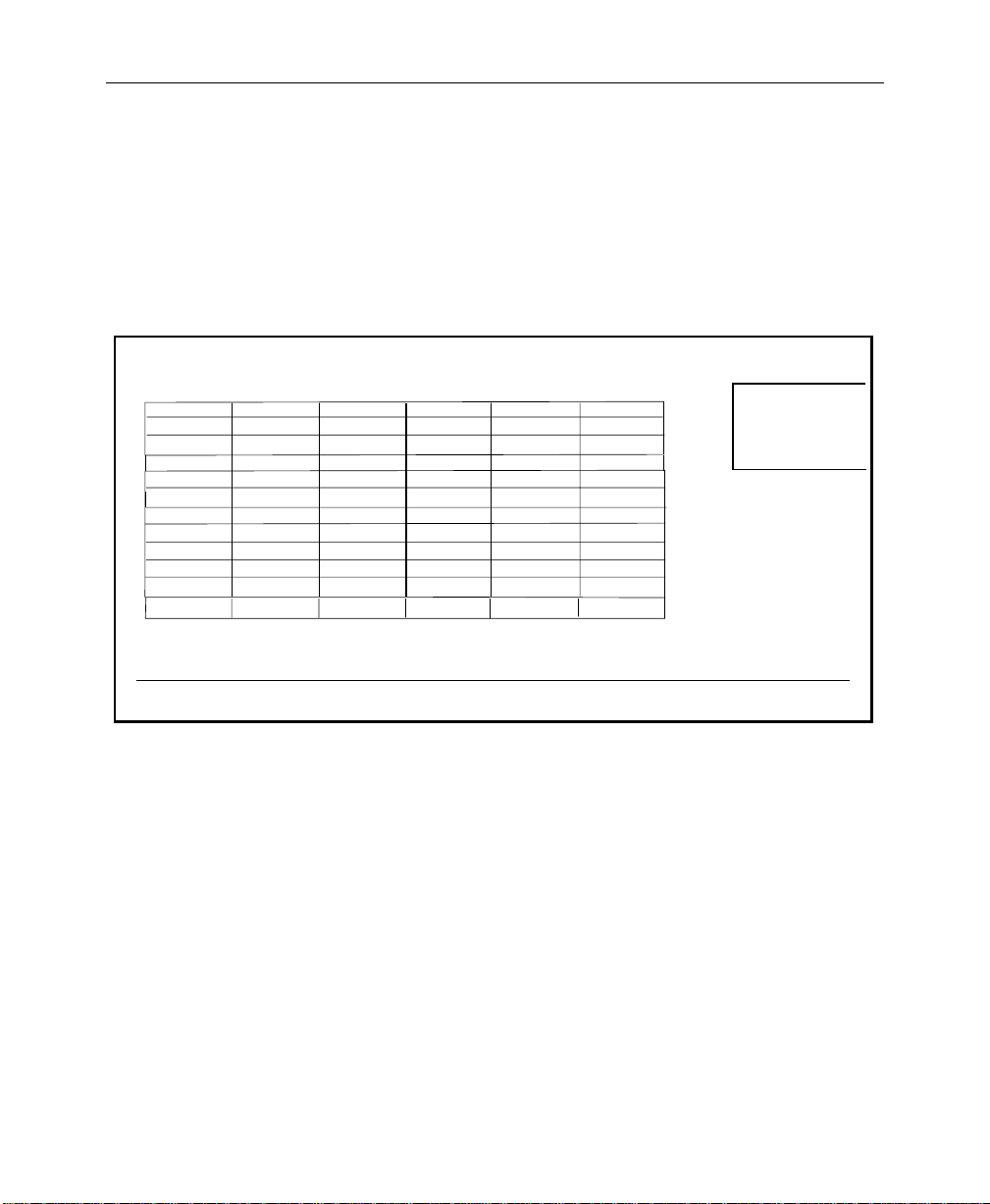
Section 2 — Startup & Configuration
Mapping Kaleidoscope Source Buttons
The DPM Kscope Source Menu allows you to map Kaleidoscope
video source crosspoints to your switcher video source
crosspoints. You may set this map to a Grass Valley default or you
may map each Kaleidoscope source button individually to the
switcher crosspoint button of your choice.
DPM K'SCOPE SOURCES MENU
config/extern if/dpm setup/dpm k'scope sources
K'SCOPE BTN K'SCOPE BTN K'SCOPE BTN
0
12
23
3
4
56
67
78
89
9
10
SWR BTN SWR BTN SWR BTN
1
4
5
10
11
11
12
13
14
15
16
17
18
19
20
21
12
13 23
14
16
17 27
18 28
19 29
20 30
21 31
22
DIAL IN SWITCHER
22
24
2515
26
23
24
S/1
S/2
S/3
S/4
S/5
ME/1
ME/2
PGM
XPT BUTTON FOR
K'SCOPE SOURCE
BUTTON
K'SCOPE BUTTON
=
2-48
SET
DEFAULTS
SWITCHER BUTTON
=
With the top soft knob, highlight the Kaleidoscope button to be
mapped, then turn the second knob to assign the desired switcher
crosspoint.
Press the SET DEFAULTS soft button to return the mapping to the
Grass Valley defaults (shown in the illustration above).
Page 85
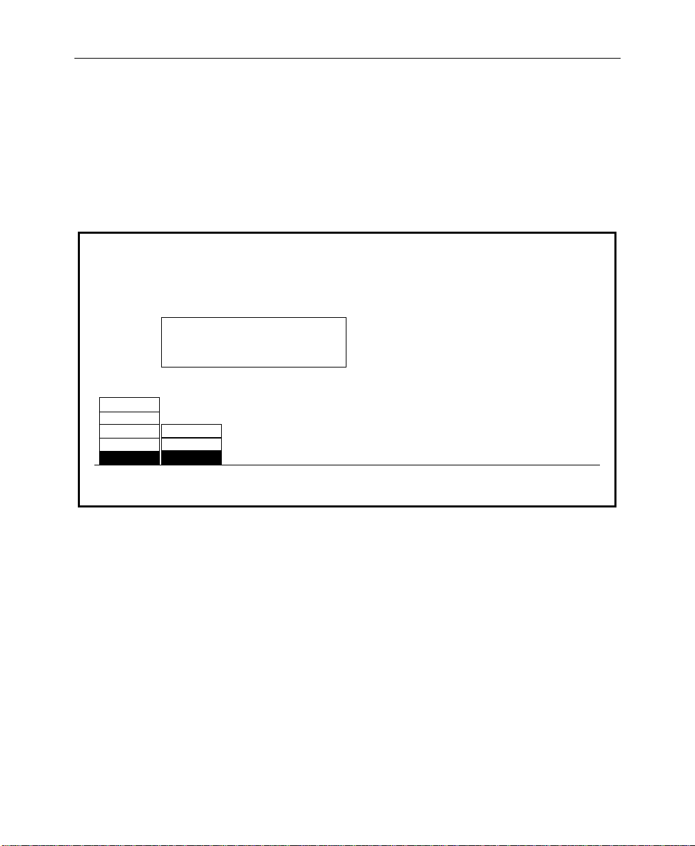
Configuring the Peripheral Interface
The Peripheral Interface Menu allows you to set up the
parameters for the Peripheral Bus II port (A3).
1. From the Configuration Menu, press EXTERN I/F>, then
PERIPHERAL I/F> to bring up the Peripheral Interface Menu.
PERIPHERAL INTERFACE MENU
config / extern if / peripheral if
Configuring External Interfaces
2400
4800
9600
19200
38400
The Peripheral Bus port is labelled
"Port A3" on the rear of the frame
ODD
EVEN
NONE
PARITYBAUD
NOTE:
electronics.
2. Select the baud rate and parity parameters for the Peripheral
Bus II port interface by incrementing to the desired settings.
These should be set to be the same for the Model 3000 and the
peripheral device. For a DPM-700, set the baud rate to 38400
and parity for NONE.
PERIPHERAL
TRIGGERS >
2-49
Page 86
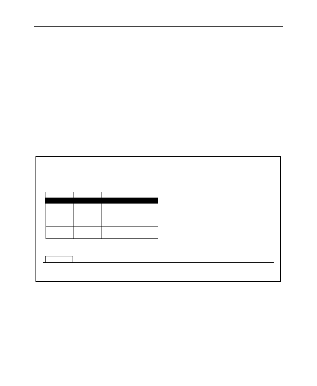
Section 2 — Startup & Configuration
Assigning Peripheral Triggers
This menu allows you to configure up to eight peripheral triggers
for the switcher (designated A through H). Each trigger is sent to
a particular address (Device Number) on the Peripheral Bus.
Once configured, these triggers can be learned into E-MEM effects
(on MISC or DPM 1–4 levels) or fired directly from this menu. Refer
to the Keyframe/Attach Peripheral Trigger Menu description in
the Operator’s Guide for attaching peripheral triggers to E-MEM
registers.
3. From the Peripheral Interface Menu, press PERIPHERAL
TRIGGERS>
to open the Peripheral Triggers Menu.
PERIPHERAL TRIGGERS MENU
config / extern if / peripheral if / peripheral triggers
A
C
D
E
F
G
H
B
TRIGGER
SELECT
DEVICE NO.
FUNCTN NO.
-
14B DPM 1
-
-
-
-
-
-
-
-
-
-
-
-
-
LEVEL
-
-
-
-
-
-
-
4. Increment TRIGGER SELECT to select the trigger to be
configured (A through H).
5. Turn the DEVICE NUMBER soft knob to select the peripheral
device to which that trigger will be sent.
FIRE
B
DEVICE NUMBER
FUNCTION NUMBER
= 1
= 4
LEVEL
= DPM 1
2-50
Page 87

Configuring External Interfaces
6. Turn FUNCTION NUMBER to select the function of the device
that will be triggered by a trigger message on the Peripheral II
bus.
7. Use the LEVEL soft knob to select which E-MEM level will
activate the selected trigger.
For a DPM-700, these functions depend on whether the DPM is
operating in trigger mode or E-MEM recall mode, as listed in
Table 2-1.
Table 2-1. DPM-700 Trigger Functions
Trigger DPM T rigger Function DPM E-MEM Recall
0 Function not defined Not valid
1 STOP DPM RECALL REGISTER 1
2 RUN DPM RECALL REGISTER 2
3 NEXT KEYFRAME DPM RECALL REGISTER 3
4 PREVIOUS KEYFRAME DPM RECALL REGISTER 4
5 STOP NEXT DPM RECALL REGISTER 5
6 REVERSE DPM RECALL REGISTER 6
7 REWIND DPM RECALL REGISTER 7
8 KEYER AUTO-TRANS DPM RECALL REGISTER 8
9 KEYER CUT DPM RECALL REGISTER 9
10 FADE TO BLACK AUTO-TRANS DPM RECALL REGISTER 10
11 FADE TO BLACK CUT DPM RECALL REGISTER 11
12 COMBINER AUTO-TRANS DPM RECALL REGISTER 12
13 COMBINER CUT DPM RECALL REGISTER 13
14 Function not defined DPM RECALL REGISTER 14
15 Function not defined DPM RECALL REGISTER 15
8. Press the main menu CONFG button to return to the
Configuration Menu.
2-51
Page 88
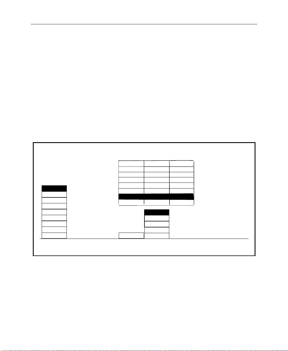
Section 2 — Startup & Configuration
Configuring GPI Outputs
GPI Output triggers each time there is a cut on the PGM Bus. This
GPI is typically connected to an external device such as a clock/
timer which is reset by each trigger. Such a clock would then
indicate how long the current source has been on air.
The duration of GPI Output Triggers can now be configured by
the number of fields. This configuration is set using the GPI
Outputs Menu.
Use the GPI Outputs Menu to set E-MEM levels for each assigned
GPI. You may also set the duration of the GPI trigger signal. This
menu is accessed from the Config/External If Menu.
GPI OUTPUTS MENU
config / external if / gpi outputs
OFF
GPI 1
GPI 2
GPI 3
GPI 4
GPI 5
GPI 6
GPI 7
GPI 8 7
PGM CUT
TRIGGER
1. Use the SELECT GPI button to select the desired GPI number.
2. Press the E-MEM LEVEL button to select the desired E-MEM
level.
3. Use the LENGTH soft knob to select the required GPI trigger
duration in fields.
4. Repeat Steps 1 through 3 for other GPIs.
1 MISC
2 MISC
3 MISC
4 MISC
5
6
7
8
SELECT
GPI
LEVEL LENGTH
1
1
1
1
MISC
MISC
MISC
MISC
MISC
DPM 1
DPM 2
DPM 3
DPM 4
E-MEM
LEVEL
1
1
1
1
LENGTH
= 1 Field
2-52
Page 89

Formatting Aux Buses
Each of the 7 aux buses consists of an “A” bus and a “B” bus. The
A buses ar e for video only. The B buses may be either video or key,
as configured by the Aux Bus Format Menu.
1. From the Configuration Menu, press AUX BUS FORMAT> to
display the Aux Bus Format Menu.
AUX BUS FORMAT MENU
config / aux bus format
Formatting Aux Buses
VIDEO
KEY KEY KEY KEY KEY
AUX
BUS 1B
VIDEO
AUX
BUS 2B
VIDEO
AUX
BUS 3B
VIDEO
AUX
BUS 4B
2. For each B bus to be configured, select either VIDEO or KEY
with the appropriate soft button.
NOTE:
For Effects Send operation, it is not necessary to configure the
B buses in this menu. When Effects Send is selected, this menu is ignored
and the corresponding B bus is automatically configured as a key.
If the Key Store is configured for video, Aux Bus 4 should also be
configured for
VIDEO
;
Any aux buses assigned to Kaleidoscope, but not used for Effects Send,
should have their B buses configured for
VIDEO
AUX
BUS 5B
VIDEO VIDEO
KEY
AUX
BUS 6B
KEY
KEY
AUX
BUS 7B
operation.
2-53
Page 90

Section 2 — Startup & Configuration
Setting User Preferences
The User Preferences Menus are used to gain access to certain
parameters that the operator may need to change.
1. From the Configuration Menu, press the USER PREFS> button
to bring up the User Preferences Menu:
USER PREFS MENU
config / user prefs
LATCH
NORMAL
SHIFT
MODE
KEYER
PREFS >
PREVIEW
PREFS >
BEEPER
PREFS >
DEFINE
DEFAULTS >
Setting Shift Lock Operation
Switcher crosspoint buses may be locked into a shifted state. This
allows ready access to input sources that have been mapped to
shifted crosspoints. Shift lock is enabled by choosing the LATCH
selection on the User Prefs Menu.
When NORMAL is selected, the SHIFT button stays lit and the bus
containing that crosspoint remains in the shifted state after a
shifted crosspoint is selected.
2-54
Page 91

Setting User Preferences
To Shift Lock a Bus
With LATCH enabled on the User Preferences Menu, press and
hold the [SHIFT] button while selecting a crosspoint. The bus
containing that crosspoint is now locked into a shifted state. Any
crosspoint selected on this bus will now be a shifted crosspoint.
The [SHIFT] button light will remain ON while the bus is in this
state.
To Unshift Lock a Bus
On a Shift Locked bus:
Press and hold the [SHIFT] button. Select a crosspoint button. The
bus is now unshifted, and the [SHIFT] button lamp is OFF.
NOTE:
revert to the unshifted state. Simply pressing [SHIFT] will not have any
effect.
You must press [SHIFT] plus a crosspoint button in order to
2-55
Page 92

Section 2 — Startup & Configuration
Setting Keyer Preferences
From the User Preferences Menu, pr ess the KEYER PREFS> button
to display the Keyer Preferences Menu:
KEYER PREFS MENU
config / user prefs / keyer prefs
ON
OFF
DSK
DROP
ON
OFF
KEY
MEMORY
CLEAR
KEY MEM >
The DSK DROP button allows you to enable or disable DSK
Drop mode.
The KEY MEMORY button allows you to turn on or off the key
memory feature.
The CLEAR KEY MEM> button opens the Clear Key Memory
Menu, which allows you to clear the key memory settings for
various areas of the switcher.
2-56
Page 93

2. From the Keyer Preferences Menu, press CLEAR KEY MEM> to
bring up the Clear Key Memory Menu.
CLEAR KEY MEMORY MENU
config / user prefs / keyer prefs / clear key mem
CURRENT
XPT
7
Press a button below to clear key memory for –
M/E 1
M/E 2
M/E 3
DSK
AUX
MASK
SECTION
SELECT
A
B
KEY 1
KEY 2
BUS
SELECT
CLEAR XPT: the current xpt on the selected bus
CLEAR BUS: all xpts on the selected bus
CLEAR SECTION: all xpts on all buses in the selected section
CLEAR SWITCHER: all xpts in the switcher
CLEAR
XPT
CLEAR
BUS
Setting User Preferences
CLEAR
SECTION
CLEAR
SWITCHER
This menu allows you to clear the key memory settings for
selected areas of the switcher.
3. With the SECTION SELECT and BUS SELECT buttons, select
the area of the switcher whose key memory you wish to clear.
To select a specific crosspoint on a bus: After selecting the
section and bus, press the specific crosspoint on the selected
bus. (The number of that crosspoint will appear in the
CURRENT XPT box in the menu.)
4. Use the CLEAR XPT, CLEAR BUS, CLEAR SECTION, or CLEAR
SWITCHER
button to clear the desired memory area.
5. Press EXIT to return to the User Preferences Menu.
2-57
Page 94

Section 2 — Startup & Configuration
Setting Preview Preferences
1. From the User Preferences Menu, press the PREVIEW PREFS>
button to display the Preview Preferences Menu.
NOTE:
PVW output connectors and the PVW Monitor(s)
PREVIEW PREFS MENU
config / user prefs / preview prefs
M/E 1
M/E 3
PGM PST
PVW
SELECT
PGM
LOOKAHEAD
PGM
PGM
AUTO
LOOKAHEAD
PGMM/E 2
ALL KEYERS
OFFM/E 2
OFF
OFF
ALL KEYERS
DELEG KEYER
OFF
DIM
PVW
2. Press PVW SELECT to select the switcher subsystem for which
you which to set the preview options: M/E 1,
M/E 2, M/E 3, or PGM PST.
It is important to note that these menu setups affect only the
ON
OFF
PUSH TO
PVW
PUSH TO PREVIEW TIMEOUT
= 3 secs
2-58
3. Press the PVW MODE button to select the preview mode
desired for the selected switcher subsystem.
Page 95

Setting User Preferences
NOTE:
The optional M/E Preview mezzanine board must be installed
in each M/E in order to select AUTO and LOOKAHEAD Preview Modes.
These selections will not be displayed in the menu if the board is not
installed.
The choice of the Preview Mode to be used depends primarily on
how many monitors you have per M/E and how you wish to use
them, as illustrated in Figure 2-5.
AUTO — Use this mode to automatically toggle between the
M/E PGM and PVW (next transition) outputs when a single
M/E monitor is used. The monitor displays the M/E PVW
output when the M/E is on air (high tally); it displays the M/
E PGM output when it is not on air (low tally).
LOOKAHEAD — Use to preview what is going on-air next.
Always shows the next transition of the selected M/E.
PGM — Use to display the PGM output of the M/E or the
PGM PST on the Preview monitor.
KEY PVW (Displayed only when PGM PST is selected) — Use
to preview DSK 1 and DSK 2 keys over the PGM PST
transition on the Preview Monitor.
2-59
Page 96
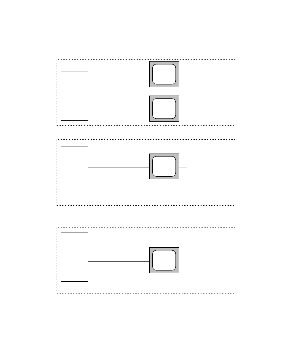
Section 2 — Startup & Configuration
2 Monitors per M/E
Switcher
Switcher
M/E 2 PGM Out
M/E 2 PVW Out
1 Monitor per M/E
PVW Out
1 Monitor per M/E
PGM
PVW
AUTO
Fixed
Lookahead
PGM Out - Low Tally
Lookahead - Hi Tally
2-60
Switcher
PVW Out
PGM
Fixed PGM
(In effect, no PVW
function enabled.)
Figure 2-5. Preview Mode Configurations
Page 97

Setting User Preferences
4. Use the DIM PVW button to assign one of the Dim Preview
modes to the selected keyer, as follows:
ALL KEYERS — Causes the preview of all keyers using a
mask on that M/E or DSK to dim on the Preview monitor .
DELEG KEYER — Causes only the preview of the keyer
that is currently delegated and inserting a mask on that
M/E or DSK to dim on the Preview monitor.
OFF — Turns off the preview dim function so that the
preview never dims on that M/E or DSK regardless of
masking.
5. Press the PUSH TO PVW button to enable/disable the push-to-
preview mode for the entire switcher. Hold down the key
delegate button (for example
panel) of the appropriate keyer for 1/2 second or more to
display the M/E look-ahead preview along with the selected
keyer output on the switched preview monitor.
When the key delegate button is released, the preview display
remains on for a programmed time-out period, as set by the
PUSH TO PREVIEW TIMEOUT
original state.
KEY 1 or KEY 2 on the Keyer
soft knob, before reverting to its
PUSH TO PREVIEW TIMEOUT — Sets how long the
preview will remain on after you have released the key
delegate button. The default value for the auto preview
timeout is 3 seconds. Any adjustments to clip or gain
resets the time-out, thus maintaining the auto preview
mode while making clip and gain adjustments.
6. Press the EXIT button to return to the User Preferences Menu.
2-61
Page 98
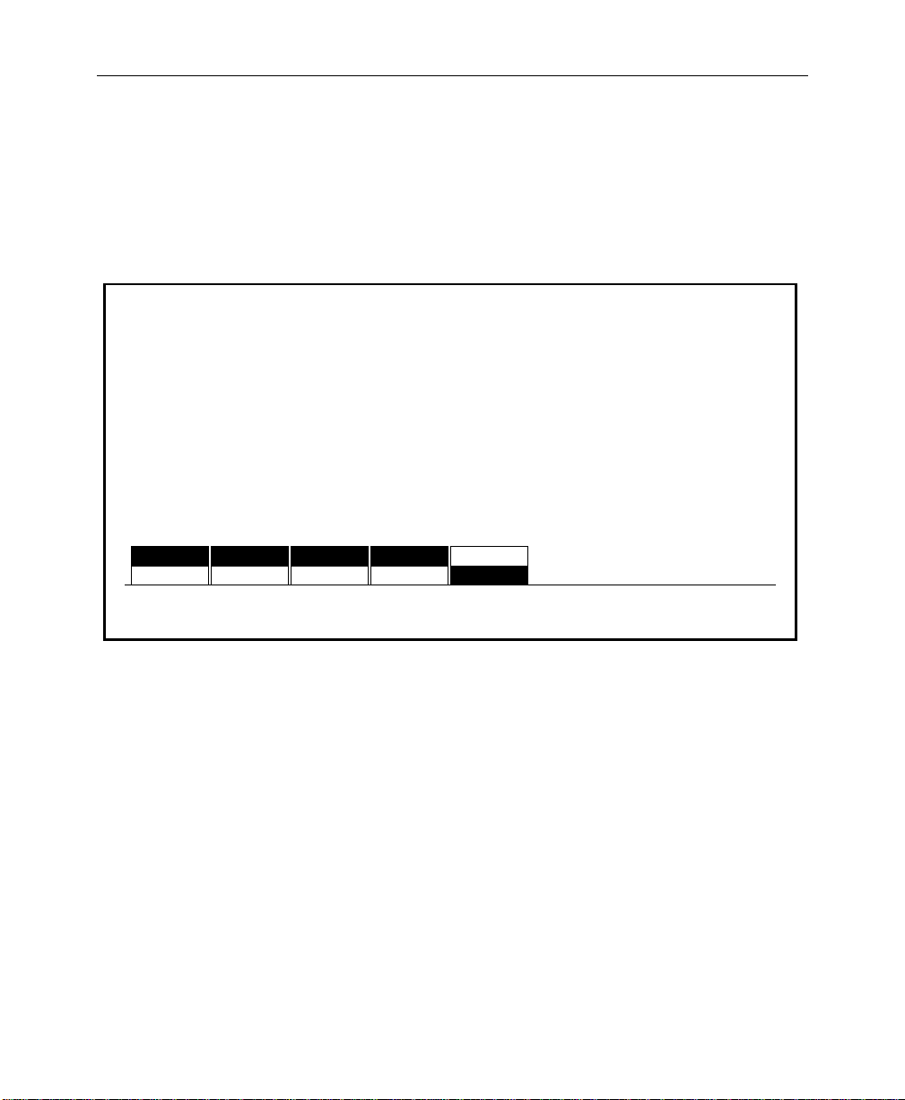
Section 2 — Startup & Configuration
Setting Beeper Preferences
You may wish to customize the beeper alert system. Beeper
preferences are selected on the Configuration/User Preferences/
Beeper Preferences Menu shown below.
BEEPER PREFS MENU
config / user prefs / beeper prefs
OFF
BEEPER
ON/OFF
OFF OFF OFF
WARNING
END OF
KNOB
KNOB
CENTER
ONON ON ON ON
OFF
INACTIVE
KNOB
2-62
BEEPER ON/OFF — Use to enable or disable the beeper
alert system.
WARNING — Use to enable or disable beeper warnings.
(For example: On the Keyer Copy Menu, if you try to copy
M/E 1 Key 1 to M/E 1 Key 1 (copy a key onto itself) you
will get a beep with Beeper Prefs selection: WARNING
ON.)
END OF KNOB — Enable or disable the beeper alert that
sounds when the knob is turned to either end of its’ range.
KNOB CENTER — Enable or disable the beeper alert that
sounds when the knob is turned to the center of its’ range.
INACTIVE KNOB — Enable or disable the beeper alert for
knobs “turned off” during the current switcher state.
Page 99
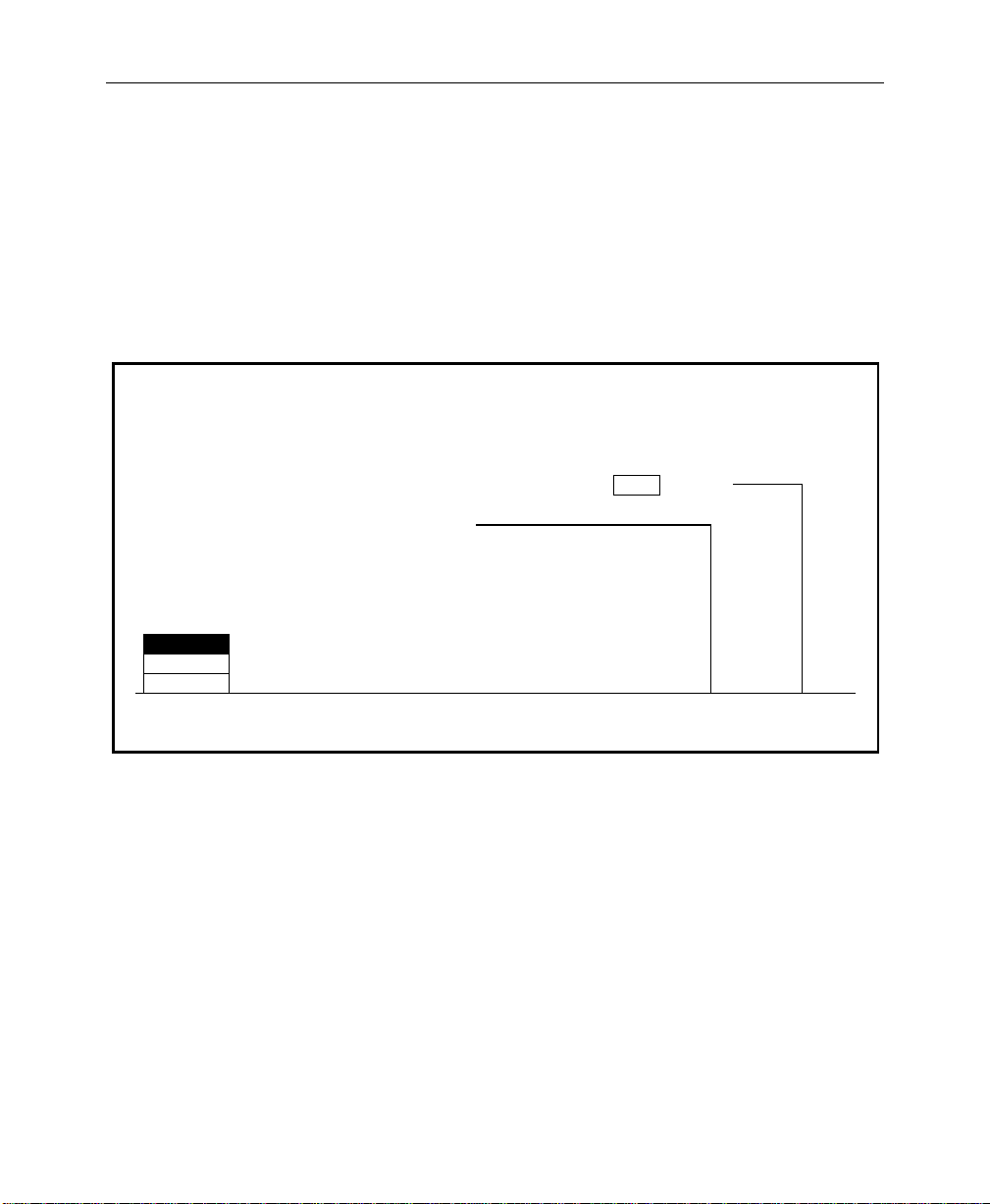
Setting User-Defined System Defaults
Setting User-Defined System Defaults
The Define Defaults Menu allows you to change the default values
that are stored in memory and used when the switcher is turned
on or the CLEAR WORK BUFR button is pressed. The values stored
in the User-Defined Default Buffer (battery-backed RAM) are
loaded into the Working Buffer when power is applied to the
switcher. This sets the initial state of the switcher parameters.
DEFINE DEFAULTS MENU
config / user prefs / define defaults
Set Default State to Current Switcher State. All M/Es will use settings.
Set Default State to GVG Factory Default.
M/E 1
M/E 2
M/E 3
M/E
SELECT
M/E 1
7. With the M/E SELECT button, select the M/E whose settings
you want to be used during power-up. (Only one set of values
is stored for the M/Es, therefore both M/Es will use the same
values at boot-up.)
8. On the switcher panel (including the selected M/E), set up the
switcher state that you want the switcher to assume when it is
turned on.
9. Press
SET DEFAULT to enter the new default values.
10. Pressing the GVG DEFAULT button will r estore the factory-set
default values to the switcher . These are stored in non-volatile
memory (ROM).
GVG
DEFAULT
SET
DEFAULT
2-63
Page 100

Section 2 — Startup & Configuration
Operating Notes
Field Dominance Selection
In the Model 3000 Switcher, all “set” changes such as crosspoint
selections and E-MEM recalls take effect during the vertical
interval of the video signal, just prior to either Field 1 or Field 2.
The Field Dominance feature in the Configuration/System
Parameters Menu allows you to specify when these changes will
take effect.
1. Press the CONFG button on the main menu subpanel, then
press the SYSTEM PARAMS> soft button in the Configuration
Menu. This will bring up the System Parameters Menu.
With Field Dominance off (FIELD DOM set to NONE), selection
changes become effective at the beginning of the next field
(immediately after the functions have been changed).
2-64
Use of Field Dominance
If the output of the Model 3000 is going to be recorded onto tape
that will later be edited along with other tape, it is important that
changes take place consistently on the same field. They can occur
on either Field 1 or Field 2 of the frame, but need to be on the same
field every time. If this is not done, there will be a “flash” at the
edit in the resulting taped video.
With FIELD 1 selected as the dominant field, if a change takes place
just prior to Field 1, the change will become effective at the
beginning of Field 1. But if the change takes place prior to Field 2,
the change will be delayed by one field so that it also becomes
effective at the beginning of the next Field 1. This way, all changes
will be synchronized to take place at the beginning of Field 1.
Similarly, if FIELD 2 were selected as the dominant field, those
changes that take place prior to Field 1 would be delayed until
Field 2.
 Loading...