

Page 1

Software Version 7.13.2
Tektronix Communications | For Licensed Users | Unauthorized Duplication and Distribution Prohibited
G10 Hardware Maintenance Guide
GeoProbe® G10
Page 2

Copyright © Tektronix, Inc. All rights reserved. Printed in the USA. Tektronix products are covered
Tektronix Communications | For Licensed Users | Unauthorized Duplication and Distribution Prohibited
by U.S. and foreign patents, issued and pending. Information in this publication supersedes that in
all previously published material. Specification and price change privileges reserved. TEKTRONIX
and TEK are registered trademarks of Tektronix, Inc. The GeoProbe system uses the SmartHeap
product for memory management. SmartHeap is a product of Compuware Corporation,
Copyright © All rights reserved. All other trade names
trademarks or registered trademarks of their respective companies.
Tektronix Communications
3033 W President George Bush Highway
Plano, Texas 75075
+1 469-330-4000 (voice)
eb
www.tekcomms.com W
site
referenced
are the service marks,
uadocfeedback@tektronix.com (Techn
Plano, Texas USA - serves North America, South Ame
+1 469-330-4581 (Customer Support voice)
uaservice@tek.com (Customer Support USA email)
London, England UK - serves Northern Eu
+44-1344-767-100 (Customer Support voice)
uaservice-uk@tek.com (Customer Support UK email
Frankfurt, Germany DE - serves Central Europe and Middle East
+49-6196-9519-250 (Customer Support voice)
uaservice-de@tek.com (Cus
Padova, Italy IT - serves Southern Europe and Middle East
+39-049-762-3832 (Customer Support voice)
uaservice-it@tek.com (Customer Su
Melbourne, Australia - serves Australia
+61 396 330 400 (Customer Support voice)
uaservice-ap@tek.com (Cu
Singapore - serves Asia and the Pacific Rim
+65 6356 3900 (Customer Support voice)
uaservice-ap@tek.com (Cus
Tektronix, Inc. Proprietary In
992-0411-08-002-140228
tomer Support DE email)
s
tomer Support Australia and APAC email)
tomer Support APAC and Australia email)
formation
ical Publications email)
rica, Latin America
rope, Middle East, and Africa
)
pport IT email)
The products and specifications, configurations, and other technical information regarding the
services described or refe
statements, technical information, and recommendations contained in this document are believed
to be accurate and reliable but are presented “as is” without warranty of any kind, express or
implied. Users must take full responsibility for their application of any products specified in this
document. Tektronix, Inc. makes no implied warranties of merchantability or fitness for a purpose
as a result of this document or the information described or referenced within, and all other
warranties, express or implied, are excluded.
Except where otherwise indicated,
planned capabilities and intended functionality offered by the product and version number
identified on the front of this document. Screen images depicted in this document are
representative and intended to serve as example images only. Wherever possible, actual screen
images are included.
renced in this document are subject to change without notice. All
the information contained in this document represents the
Page 3

WHAT’S NEW IN G10 HARDWARE VERSION 7.13.2?
Tektronix Communications | For Licensed Users | Unauthorized Duplication and Distribution Prohibited
Feature ID Description Refer to:
F-02470 New Applications Blade
G10 probes support a new IAP320 application blade.
Chapter 1, G10 Probe
Configurations
Chapter 3, Blades and
RTMs
Rev. 002-140228
Page 4

User Documentation
Table of Contents
Tektronix Communications | For Licensed Users | Unauthorized Duplication and Distribution Prohibited
What’s New in G10 Hardware Version 7.13.2? ............................................................. 3
Chapter 1 G10 Probe Overview ........................................................................................................... 9
Overview ...................................................................................................................... 9
G10 Probe Configurations .......................................................................................... 10
G10 Architecture Overview ......................................................................................... 11
Data Collection and Processing............................................................................ 11
Line Rate Processing—Iris Interface Card (IIC) ............................................... 12
User Plane and Control Plane Processing—Iris Interface Card (IIC)
and Application Blade .................................................................................... 12
Storage Subsystem—Store to Disk ...................................................................... 12
G10 Hardware Components ....................................................................................... 13
G10 Front View .................................................................................................... 13
G10 Rear View ..................................................................................................... 14
Network Connectivity.................................................................................................. 15
Default Port Settings ............................................................................................ 16
Time Synchronization.................................................................................................. 17
G10 Media Probe Configuration.................................................................................. 18
G10 Control Plane Probe Configuration ...................................................................... 19
Chapter 2 Chassis Subsystem........................................................................................................... 22
Overview .................................................................................................................... 22
Shelf Manager ............................................................................................................ 23
Rear Panel LEDs .................................................................................................. 24
Rear Panel Connectors ........................................................................................ 25
Power Entry Modules (PEMs)...................................................................................... 26
DC PEMs ............................................................................................................. 26
Front Panel LEDs........................................................................................... 27
AC PEMs ............................................................................................................. 28
Front Panel LEDs........................................................................................... 28
Fan Trays.................................................................................................................... 29
Electro-Static Discharge Points................................................................................... 30
G10 Hardware Maintenance Guide 7.13.2 4
Page 5

Rev. 002-140228
Tektronix Communications | For Licensed Users | Unauthorized Duplication and Distribution Prohibited
Chapter 3 Blades and RTMs ..............................................................................................................31
Overview .....................................................................................................................31
Iris Interface Card ........................................................................................................32
IIC LEDs................................................................................................................32
IIC200 ...................................................................................................................34
IIC200 LEDs ...................................................................................................34
FPC200 AMC .................................................................................................35
LPC200 AMC .................................................................................................37
IIC200 RTMs ..................................................................................................39
IIC100 ...................................................................................................................42
FPC100 AMC .................................................................................................43
LPC100 AMC .................................................................................................45
IIC100 RTMs ..................................................................................................46
Applications Blade .......................................................................................................53
Table of Contents
IAP320/IAP200 .....................................................................................................54
IAP320 ...........................................................................................................55
IAP200 ...........................................................................................................58
PRM300 RTM/PRM200 RTM .........................................................................60
IAP100..................................................................................................................63
IAP100 LEDs ..................................................................................................64
IAP100 Connectors ........................................................................................65
SAS AMC .......................................................................................................66
IAP100 RTMs .................................................................................................67
10G Interconnect Card ................................................................................................70
10G Interconnect Card LEDs ..........................................................................71
10G Interconnect Card Connectors ................................................................72
G10 Hardware Component Name Reference ..............................................................72
Chapter 4 Storage Subsystem............................................................................................................74
SAS Storage Arrays.....................................................................................................74
Supported Models ................................................................................................75
Storage Enclosure Features ..................................................................................75
Disk Enclosure Front Panels ........................................................................................77
SA100R, SA100J, SA200R, and SA200J Front Panel ...........................................77
SA210J Front Panel ..............................................................................................77
Front Panel LEDs ..................................................................................................78
Disk Enclosure Rear Panel...........................................................................................79
SA200R Controller Enclosure Rear Panel ..............................................................79
G10 Hardware Maintenance Guide 7.13.2 5
Page 6

Rev. 002-140228
Tektronix Communications | For Licensed Users | Unauthorized Duplication and Distribution Prohibited
SA200R Controller Enclosure Connectors ......................................................81
SA100R Controller Enclosure Rear Panel ..............................................................81
SA100R Controller Enclosure Connectors ......................................................83
SA100J, SA200J, and SA210J Expansion Enclosure Rear Panel ..........................84
Expansion Enclosure Connectors ...................................................................85
Chapter 5 Maintenance Guidelines .....................................................................................................86
Overview .....................................................................................................................86
G10 Maintenance Procedures .....................................................................................87
Field Replaceable Units .........................................................................................87
Removing and Replacing a PEM ...........................................................................89
Replacing a DC PEM ......................................................................................89
Replacing an AC PEM ....................................................................................91
Replacing the Fan Tray .........................................................................................94
Replacing G10 Chassis Air Filters ..........................................................................97
Table of Contents
Replacing the Top Air Filter .............................................................................97
Replacing the Bottom Air Filter .......................................................................99
G10 Blade Removal/Replacement Procedures....................................................102
IAP100 .........................................................................................................102
SAS AMC (IAP100) .......................................................................................105
IAP200/IAP320.............................................................................................106
Iris Interface Card (IIC100 or IIC200) .............................................................108
LPC and FPC AMCs (IIC100 or IIC200).........................................................115
RTMs ...........................................................................................................116
10G Interconnect Card .................................................................................118
Replacing G10 Shelf Managers (SHMMs) ............................................................120
Replacing the First (Standby) SHMM ............................................................120
Replacing the Second (Active) SHMM ..........................................................121
Serial Over LAN (SOL) Support ...........................................................................122
G10 Probe and Array Start Up/Shut Down Sequence .........................................122
Start Up Procedure.......................................................................................122
Shut Down Procedure ..................................................................................124
Storage Array Maintenance Procedures.....................................................................125
Storage Array Maintenance Guidelines................................................................125
Replacing a Power Supply ..................................................................................126
Removing the Power Supply.........................................................................126
Installing the Power Supply...........................................................................128
Bezel (Air Filter) Procedures.................................................................................129
G10 Hardware Maintenance Guide 7.13.2 6
Page 7

Rev. 002-140228
Tektronix Communications | For Licensed Users | Unauthorized Duplication and Distribution Prohibited
Table of Contents
Installing the Bezel ........................................................................................129
Removing the Air Filter ..................................................................................130
Replacing the Air Filter ..................................................................................132
Replacing a Controller or Expansion Module .......................................................134
Removing the Controller Module...................................................................134
Installing the Controller Module
Replacing a Drive Module....................................................................................137
Removing Air Management Modules ............................................................137
Installing Drive Modules ................................................................................138
Replacing the Disk Array Chassis ........................................................................139
Removing the Disk Array Chassis .................................................................140
Installing the Disk Array Chas
Chapter 6 System Operating Specifications......................................................................................143
Overview ...................................................................................................................143
Physical Specifications ..............................................................................................144
Power and Ground Requirements .............................................................................145
DC Power Requirements.....................................................................................145
AC Power Requirements .....................................................................................146
Environmental Specifications...............................................................................147
Regulatory Specifications ..........................................................................................147
Safety Compliance ..............................................................................................147
EMC Standards ..................................................................................................148
.............................
sis
...................................................................141
........................................136
CE Mark..............................................................................................................149
NEBS..................................................................................................................149
ETSI Compliance ................................................................................................149
Safety Guidelines .......................................................................................................150
Equipment Use ...................................................................................................150
Handling the GeoProbe G10 ...............................................................................150
Damage to Circuits .............................................................................................150
GeoProbe G10 Power Disconnect ......................................................................150
Circuit Protection ................................................................................................151
FP100 Fuse Panel ........................................................................................151
G10 Equipment Warning Labels ................................................................................153
Appendix A SFP Reference ........................................................................................................
Monitored Ports SFPs ...............................................................................................154
1 Gb Port SFPs .........................................................................................................155
1000base-LX Fiber..............................................................................................155
...
.....154
G10 Hardware Maintenance Guide 7.13.2 7
Page 8

Rev. 002-140228
Tektronix Communications | For Licensed Users | Unauthorized Duplication and Distribution Prohibited
Table of Contents
1000base-SX Fiber .............................................................................................156
1000base-T Copper............................................................................................156
10 Gb Port SFPs .......................................................................................................157
10Gbase-SR Fiber ..............................................................................................158
10Gbase-LR Fiber...............................................................................................158
Minimum Signal Levels ..............................................................................................158
Installing SFPs ...........................................................................................................159
IIC200 ..........................................................................................................160
IIC100 ..........................................................................................................161
TRM100 RTM...............................................................................................161
PRM200 RTM or PRM300 RTM ...................................................................162
SRM200 RTM...............................................................................................162
G10 Hardware Maintenance Guide 7.13.2 8
Page 9

User Documentation
OVERVIEW
Tektronix Communications | For Licensed Users | Unauthorized Duplication and Distribution Prohibited
G10 Probe Overview
The newest member of the GeoProbe family was designed specifically to address high
bandwidth IP interfaces with a distributed architecture optimized to handle larger traffic
volumes.
With native IPv4 and IPv6 support, the GeoProbe G10 offers the following benefits:
Optimized for portions of the operator networks with high volumes of voice and data
IP traffic.
Additional on-board capabilities improve usability and efficiencies: Store to Disk (S2D)
supports configurable packet capture rates with expandable storage configurations.
Beyond quantifiable performance metr
configuration, and maintenance.
Automated workflows facilitate installation and configuration tasks.
Scheduled group downloads streamline maintenance windows with built-in
reversibility commands for ensuring upgrade integrity.
ics, the GeoProbe G10 enables low-touch installation,
G10 Hardware Maintenance Guide 7.13.2 9
Page 10

Rev. 002-140228
Tektronix Communications | For Licensed Users | Unauthorized Duplication and Distribution Prohibited
G10 Probe Overview
G10 PROBE CONFIGURATIONS
Table 1.1 describes the different GeoProbe G10 configuration options.
Table 1.1 - G10 Configuration Options
G10 Configuration Supported HW Configuration Details Refer to:
1
Standalone 8 x 1G IIC100 + SRM100RTM
Standalone Mixed Model
(1G and 10G)
Media Probe IIC100 + TRM100 RTM
Control Plane Probe IIC100 + TRM100 RTM
a. This configuration is only supported for standalone probe configurations monitoring eHRPD.
b. Due to the Media probe and Control Plane probe configurations, deployments with IIC100/TRM100 RTM have a maximum
of TWO 10G physical ports available to monitor traffic.
c. The control plane probe only supports the IIC100/IAP200 configuration; the IIC100/IAP320 configuration is not supported.
IAP100 + PRM100 RTM
IAP200 + PRM200 RTM
IAP320 + PRM300 RTM
IIC100 + TRM100 RTM
IIC200 + SRM200 RTM
IIC200 + TRM100 RTM
IAP100 + PRM100 RTM
IAP200 + PRM200 RTM
IAP320 + PRM300 RTM
IIC200 + SRM200 RTM
IAP100 + PRM100 RTM
IAP200 + PRM200 RTM
IAP320 + PRM300 RTM
IIC200 + SRM200 RTM
IAP100 + PRM100 RTM
IAP200 + PRM200 RTM
IAP320 + PRM300 RTM
a
b
b,c
Single chassis probe configuration
Supports 8 physical 1G connections
Can be upgraded in the field to a Mixed
Model
Single chassis probe configuration
Provides support for both 1G and 10G
Ethernet connections on one probe.
Various combinations are supported with
the following maximums:
- Maximum support of 8 total ports (1G +
10G)
- Maximum support of 4 10G ports
Two-chassis probe configuration for supporting
RTP media monitoring
Primary Chassis supports:
- Maximum of 8 total ports (1G + 10G)
- Maximum of 4 10G ports
Expansion Chassis provides additional
data processing support
Two-chassis probe configuration for supporting
Mobility Management Entity (MME) monitoring
Primary Chassis supports:
- Maximum of 8 total ports (1G + 10G)
- Maximum of 4 10G ports
Expansion Chassis provides additional
data processing support
Page 13
Page 13
Page 18
Page 19
G10 Hardware Maintenance Guide 7.13.2 10
Page 11

Rev. 002-140228
Tektronix Communications | For Licensed Users | Unauthorized Duplication and Distribution Prohibited
G10 ARCHITECTURE OVERVIEW
As the foundation for Tektronix Communications' Network Intelligence solution, the GeoProbe
G10 efficiently and comprehensively handles virtua lly all data acquisition and processing tasks
within the Iris architecture.
Data is captured directly from the network in a passive and non-intrusive mode, as
opposed to information provided in vendor-specific format by individual network
elements. As a result, carriers can gain an independent view regardless of which
vendor's equipment is deployed in their network.
Serving as a processing hub, the GeoProbe G10 eliminates the need for external
processing equipment-reducing the number of system components required and
ultimately conserving LAN/WAN bandwidth between system elements.
Offering independence from a larger centralized storage server, the GeoProbe
G10 facilitates streaming, real-time, programmable record feeds and real-time
session traces
.
G10 Probe Overview
1
Data Collection and Processing
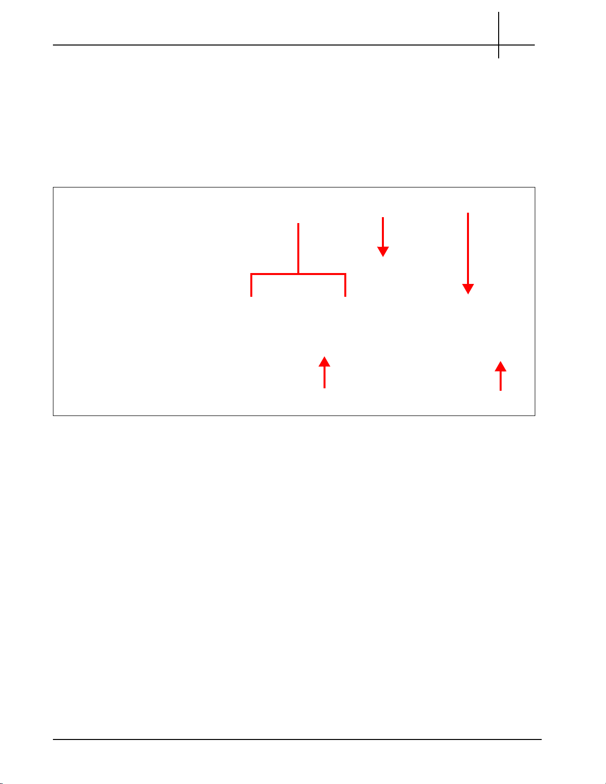
As illustrated in Figure 1.1, the GeoProbe G10 connects to the monitored network via a
physical interface at the link port. Raw packets are pr
Iris Interface Card (line rate processing functions) and forwarded (stream to disk functions) to
the Storage Subsystem.
In parallel, the Iris Interface Card sends contro
correlation, xDR generation, and KPI aggregation (control-plane processing functions).
After the packets are processed, the resulting xDRs, KPIs, and processed packets are made
available
for use by the various Iris Network Management applications.
ocessed in real time as they reach the
l plan
e traffic to the Application Blade for
Figure 1.1 - GeoProbe Data Flow
G10 Hardware Maintenance Guide 7.13.2 11
Page 12

Rev. 002-140228
Tektronix Communications | For Licensed Users | Unauthorized Duplication and Distribution Prohibited
Line Rate Processing—Iris Interface Card (IIC)
G10 Probe Overview
Consisting of a tiered pair of NPUs, the Iris Interface Card is able to process raw packets at
line rate speed with a distributed internal architecture and purpose-specific processing
functions.
Packet Processor NPU-packet classification with fast processing requirements and
lower memory requirements.
Flow Processor NPU-flow specific criteria processing across multiple packets with
higher memory requirements.
1
The Iris Interface Card’s dual NPU architecture allows
either NPU as desired-allowing additional processing power to be added incrementally as
needed and available.
for independent upgrades of each or
User Plane and Control Plane Processing—Iris Interface Card (IIC) and Application Blade
As the GeoProbe G10 architecture can support both User p lane and Control pla ne processing
with the same hardware, domain-specific sizing rules have been applied to maximize
processing performance for both traffic types.
rd h
While the Iris Interface Ca
Plane is forwarded directly to the x86 Application Blade for analysis, correlation and
processing functions.
andles the majority of the User Plane processing, the Control
Storage Subsystem—Store to Disk
In addition to I/O ports, interface processors and application boards, the GeoProbe G10
architecture relies upon a storage subsystem to further optimize processing functions.
Native Store to Disk (S2D) capabilities ensure line rate proces
capturing and storing monitored packets for use with applications requiring more extensive
and expansive data collection.
sing performance integrity by
ra
The incorporation of a RAID dual controller disk ar
provides the additional capacity required.
Refer to Storage Subsyste m for more det ail s about the storage system hardwa re component s.
G10 Hardware Maintenance Guide 7.13.2 12
y with every GeoProbe G10 installation
Page 13
Rev. 002-140228
ESD Bond Point
Power Entry
Modules
Iris Interface Card
(IIC200)
Application Blade
Fan Tray
Tektronix Communications | For Licensed Users | Unauthorized Duplication and Distribution Prohibited
G10 HARDWARE COMPONENTS
The following sections highlight the G10 hardwa re com p onen ts.
G10 Front View
Figure 1.2 shows the front view of the GeoProbe G10.
G10 Probe Overview
1
Figure 1.2 - G10 Probe Front View
The front view of the G10 system provides access to the following hardware components:
Iris Interface Card (IIC200 or IIC100)
Applications Blade (IAP320/IAP200 or IAP100)
Two Power Entry Modules (PEMs) (AC or DC)
Fan Trays (one air inlet fan tray and a second fan tray located on the rear of the G10)
Electro-Static Discharge Points
G10 Hardware Maintenance Guide 7.13.2 13
Page 14
Rev. 002-140228
ESD Bond Point
SHmm Shelf Managers
Applications Blade RTM
AC or DC Power Connectors
Fan Tray
SRM200 RTM
Tektronix Communications | For Licensed Users | Unauthorized Duplication and Distribution Prohibited
G10 Rear View
G10 Probe Overview
1
Figure 1.3 shows rear views of the GeoProbe G10. The IIC RTM installed in Slot 2 (top slot)
varies depending on the G10 configuration.
Figure 1.3 - G10 Probe Rear View
The rear view of the GeoProbe G10 system provides access to the following hardware
compone
nts:
Slot 2 (Top)—Installed IIC RTM varies per G10 model:
- 8x1G Model: SRM100 R
- Mixed 1G and 10G Model: SRM2
TM (Connects to IIC100)
00 RTM (connects to IIC200) or TRM100 RTM
(connects to IIC100 or IIC200)
Slot 1 (Bottom)—Applications Blade RTM (PRM300 RTM/PRM200 RTM or PRM100
RTM)
Redundant Shelf Manager (SHmm)
Fan Trays (front to rear air flow)
Rear connection for power cables
Electro-Static Discharge Points
G10 Hardware Maintenance Guide 7.13.2 14
Page 15

Rev. 002-140228
Tektronix Communications | For Licensed Users | Unauthorized Duplication and Distribution Prohibited
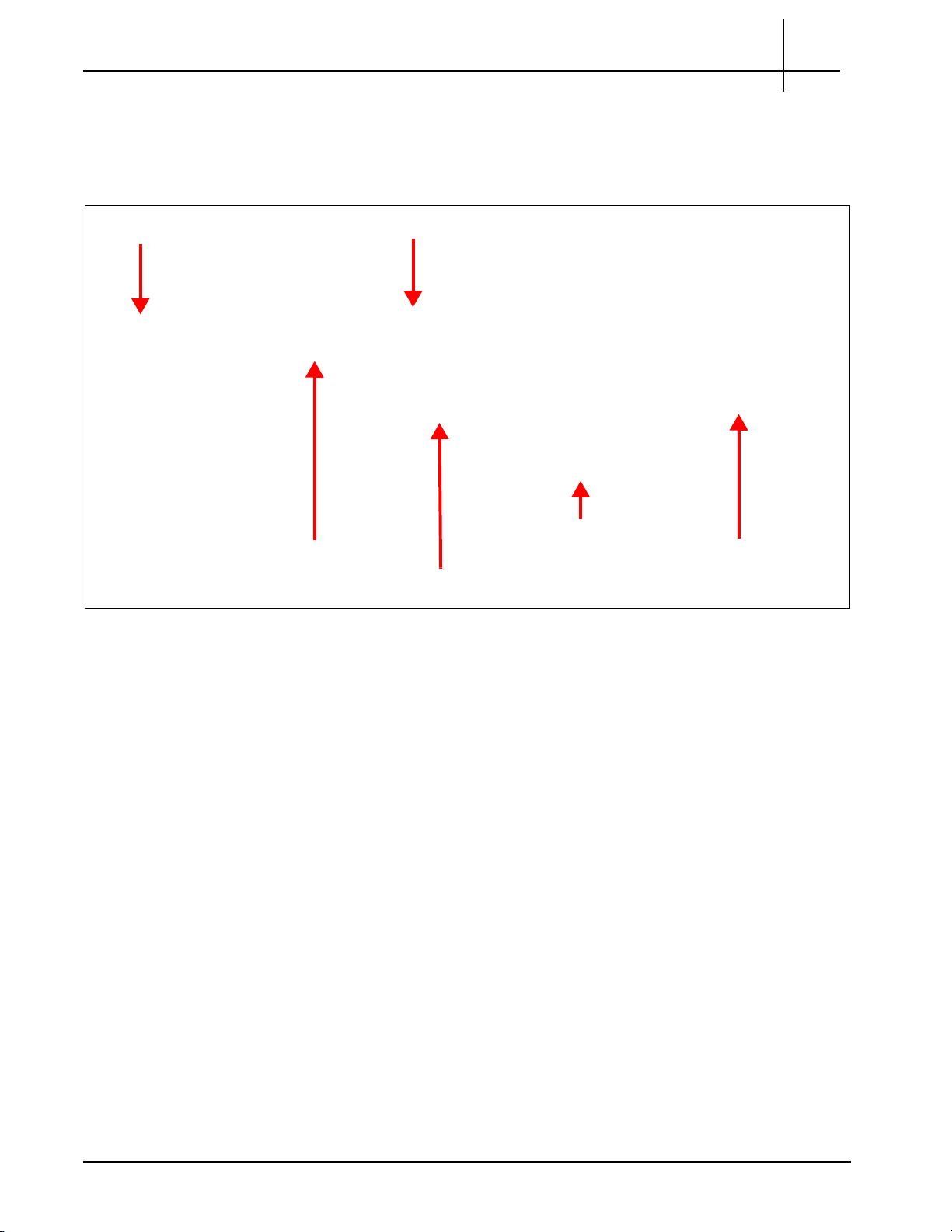
NETWORK CONNECTIVITY
A G10 deployment currently requires that the customer provide three Ethernet connections
and associated addresses on the same subnet (see Figure 1.4):
Primary Interface that connects the G10 to the Iris server. This enables probe
maintenance and configuration, as well as delivery of network traffic statistics and
detailed data to the server for display in IrisView applications. The Primary Interface
supports 100/1000 Mbps (IAP100) and 100/1000/10000 Mbps (PRM200/PRM300
RTM) Ethernet physical connections; it requires at least 100 Mbps connectivity. The
primary interface can be configured as non-redundant or re dunda nt. Refer to the G10
Installation Guide for details.
OAM Interfaces (2) that connect to the Shelf Management Modules (ShMM) on the
rear of the chassis. The SHmms provide a central management point for controlling
the operation of the chassis, for providing probe status, and for monitoring the alarm
conditions. The OAM interfaces support 10/100 Mbps Ethernet physical connections.
They require at least 10Mbps connectivity to the Iris server for management.
Figure 1.4 shows a diagram of the required Ethernet connections for G10 configurations
using the IAP200/PRM200 RTM or IAP320/PRM300 RTM configurations. Primary Interface 2
t B) is optional and only used in redundant configurations.
r
(Po
G10 Probe Overview
1
Figure 1.4 - Ethernet Connections
G10 Hardware Maintenance Guide 7.13.2 15
Page 16

Rev. 002-140228
Tektronix Communications | For Licensed Users | Unauthorized Duplication and Distribution Prohibited
Default Port Settings
Table 1.2 lists the default port settings for the G10 probe.
Table 1.2 - Default Port Settings
G10 Probe Overview
1
G10 Component Ports Supported
e
eds
Sp
LPC200 (IIC200 1G 1G No
LPC200 (IIC200) 10G/1G 10G/1G No
LPC100 (IIC100) All 1G No
SRM200 10G 10G No
TRM100 10G 10G No
PRM300 ETH A-D 10G/1G/100M Yes
PRM200 ETH A-D 10G/1G/100M Yes
IAP320 ETH 1G/100M Yes
IAP200 ETH 1G/100M Yes
IAP100
SHMM MGMT 100M Yes
a
a. Not supported on Control Plane or Media probes.
ETH A, B 1G/100M Yes
Autonegotiation?
G10 Hardware Maintenance Guide 7.13.2 16
Page 17

Rev. 002-140228
Tektronix Communications | For Licensed Users | Unauthorized Duplication and Distribution Prohibited
TIME SYNCHRONIZATION
The GeoProbe G10 system time stamps all captured messages, generated alarms, and
events to a common time base, allowing the Iris system to provide detailed, network-wide
traces and event occurrence reporting. Inter-node timing and message paths can also be
analyzed throughout the network.
The G10 Probe supports NTP timing and IRIG timing as described in Table 1.1. G10 probe
timing is configured in IrisView OAM; r
Timing Support Description
ef
er to the Admin Online Help for details.
Table 1.1 - G10 Probe Timing
G10 Probe Overview
1
NTP Timing from Defined
NTP Servers
IRIG Timing from Master
G10
IRIG Timing from Third-
t
y Source
Par
G10 probes support multiple NTP servers, defined at the systemlevel; system admins c
G10 probes select the best available NTP server from the list an d use
it as their timing reference.
Customize NTP timing at the probe-level by adding or removing NTP
v
ers for a specific probe
ser
G10s support IRIG timing references to and between probes allowing
for greater monitoring ac
Support for the IRIG timing interface allows G10 probes to share
timing with other G10 probes and with 14U and 2U GeoProbes. A
G10 probe can operate as an IRIG master or an IRIG slave.
The G10 designated as the IRIG timin
have a valid timing reference such as NTP. The IRIG slaves use IRIG
timing reference from the IRIG master G10; however, the slave G10s
also require NTP timing reference for the time of day.
G10 probes support receiving IRIG timing from a third-party source,
such as GPS.
an define up to 11 servers for the Iris system.
curacy at facilities with multiple probes.
master to other probes must
g
G10 Hardware Maintenance Guide 7.13.2 17
Page 18

Rev. 002-140228
Tektronix Communications | For Licensed Users | Unauthorized Duplication and Distribution Prohibited
G10 MEDIA PROBE CONFIGURATION
To support RTP monitoring, Tektronix also provides a multiprobe configuration called the G10
Media Probe. The G10 Media probe consists of two G10 chassis with the supported
configurations listed in Table 1.3. See Figure 1.5 and Figure 1.6 for a graphical view of the
media probe configuration.
The IICs within a multiprobe configuration must be the same model, either IIC100 or
IIC200. You cannot install mix IIC100s and IIC200s within the same multiprobe
configuration.
Table 1.3 - G10 Media Probe Configurations
Chassis Supported Blades
Primary Chassis Slot 1 (Bottom) IAP200 + PRM200 RTM OR
Slot 2 (Top) IIC200 + SRM200 RTM OR
Expansion Chassis Slot 1 (Bottom) IIC200 + SRM200 RTM OR
G10 Probe Overview
IAP320 + PRM300 RTM
IIC100 + TRM100 RTM
IIC100 + TRM100 RTM
1
Slot 2 (Top) IIC200 + SRM200 RTM OR
IIC100 + TRM100 RTM
For details about the components of the media probe, refer to the appropriate sections in this
guide. For information about installing and cabling the media probe, refer to the G10 Media
Installation Guide.
Figure 1.5 shows the front view of the G10 media probe components (IIC200 version).
Figure 1.5 - G10 Media Probe Front
G10 Hardware Maintenance Guide 7.13.2 18
Page 19
Rev. 002-140228
Tektronix Communications | For Licensed Users | Unauthorized Duplication and Distribution Prohibited
G10 Probe Overview
Figure 1.6 shows the rear view of the G10 media probe components (IIC200 version).
1
Figure 1.6 - G10 Media Probe Rear
G10 CONTROL PLANE PROBE CONFIGURATION
The G10 Control Plane probe configuration is designed for handling additional contr ol-plane
capacity for one Mobility Management Entity (MME) or several pooled MMEs. This probe
supports capture of the protocols listed in Table 1.4.
Table 1.4 - Control Plane Probe Supported Protocols
VoIP Protocols LTE Protocols
SIP
MGCP
H.323
H.248
DIAMETER
DNS
SIGTRAN
S1AP (S1-MME)
DIAMETER (S6a)
GTPv2-C (S10, inter-MME)
DNS
SgsAP
G10 Hardware Maintenance Guide 7.13.2 19
Page 20
Rev. 002-140228
Tektronix Communications | For Licensed Users | Unauthorized Duplication and Distribution Prohibited
The G10 Control Plane probe consists of two G10 chassis with the supported configurations
listed in Table 1.5. Refer to Figure 1.7 and Figure 1.8 for a graphical view of the control plane
probe configuration.
Pr
Table 1.5 - G10 Control Plane
Chassis Supported Blades
Primary Chassis Slot 1 (Bottom) IAP200 + PRM200 RTM OR
obe Configurations
IAP320 + PRM300 RTM
G10 Probe Overview
1
Slot 2 (Top) IIC200 + SRM200 RTM OR
IIC100 + TRM100 RTM
Expansion Chassis Slot 1 (Bottom) IAP200 + PRM200 RTM OR
IAP320 + PRM300 RTM
Slot 2 (Top) IAP200 + PRM200 RTM OR
IAP320 + PRM300 RTM
a. The control plane probe only supports the IIC100/IAP200 configuration; the IIC100/IAP320
configuration is not supported.
For details about the components of the control plane
in this guide. For information about installing and cabling the control plane probe, refer to the
G10 Control Plane Installation Guide.
Figure 1.7 shows the front view of the G10 Control Plane probe components.
probe, refer to the appropriate sections
a
Figure 1.7 - G10 Control Plane Probe (Front)
G10 Hardware Maintenance Guide 7.13.2 20
Page 21

Rev. 002-140228
Tektronix Communications | For Licensed Users | Unauthorized Duplication and Distribution Prohibited
G10 Probe Overview
Figure 1.8 shows the rear view of the G10 Control Plane probe components.
1
Figure 1.8 - G10 Control Plane Probe (Rear)
G10 Hardware Maintenance Guide 7.13.2 21
Page 22

User Documentation
OVERVIEW
Tektronix Communications | For Licensed Users | Unauthorized Duplication and Distribution Prohibited
Chassis Subsystem
The Chassis subsystem is a high-availability Advanced TCA that integrates cooling, power
distribution, and shelf management into an off-the-shelf platform, which allows you to add
GeoProbe G10 service-related hardware and software. The Chassis subsystem of the
GeoProbe G10 enables scalable reliability through the use of either independent or redundant
functions throughout the chassis. Most electronic modules, blades and cards are Field
Replaceable Units (FRUs).
The Chassis subsystem contains the
Shelf Manager
Power Entry Modules (PEMs)
Fan Trays
G10 Hardware Maintenance Guide 7.13.2 22
following main hardware component
s:
Page 23
Rev. 002-140228
Shelf Manager Modules (SHmms)
Tektronix Communications | For Licensed Users | Unauthorized Duplication and Distribution Prohibited
SHELF MANAGER
The Shelf Manager (SHmm) is the central management unit of the shelf and designed
specifically for the AdvancedTCA systems. Its purpose is to monitor, control and ensure
proper operation of the shelf and all other components of the Advance d TCA shelf. The shelf
manager reports anomalies and errors and takes corrective actions if required (for example,
increases the speed of the fans). Alarm states are displayed from the LEDs of the shelf’s
alarm panel. The shelf manager performs the following functions:
Retrieve FRU inventory information
Receive events from sensors of the shelf
Monitor and control the temperature of the shelf
Reports errors
Execute corrective actions
Manage interconnect resources to prevent damage of the blades due to hot swap
Chassis Subsystem
2
The shelf manager consists of two shelf manager modules (SHmms) located on the back of
the Ge
oProbe G10 (Figure 2.1).
Figure 2.1 - Shelf Manager Modules (SHmms)
The modules have an Ethernet port that connect to the Iris server for maintenance. The ports
are RJ4
5 jacks each capable of connecting to 10/100 Mbps networks. The modules provide
redundant shelf management functionality utilizing an active/ standby architecture and is
based on a proven shelf management design.
G10 Hardware Maintenance Guide 7.13.2 23
Page 24
Rev. 002-140228
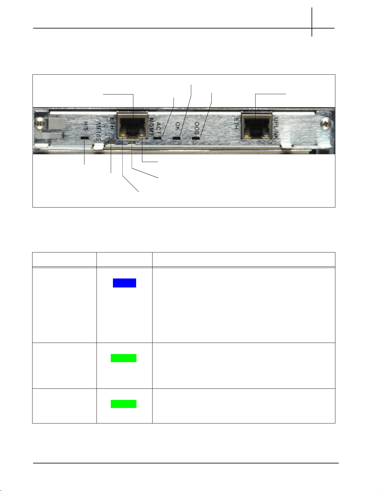
Base Channel 1
Ethernet Management Link
Base
Channel 2
Ethernet
Management Activity
Hot Swap Indicator
ACT MGMT
OK
OOS
Ethernet
Management
Connector
Ethernet
Uplink
Connector
Tektronix Communications | For Licensed Users | Unauthorized Duplication and Distribution Prohibited
Rear Panel LEDs
Figure 2.2 shows the SHmm LEDs on the rear of the G10.
Chassis Subsystem
2
Figure 2.2 - SHmm LEDs
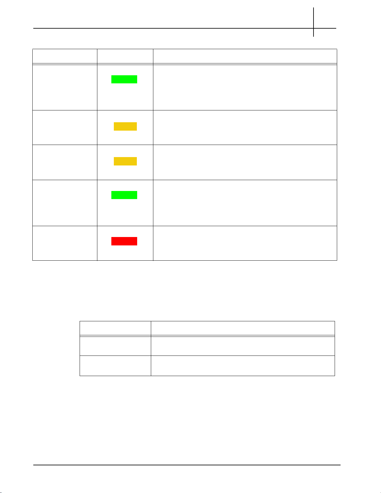
Table 2.1 describes the SHmm LED indicators.
Table 2.1 - LED Indicators of the Shmm
LED LED Color Description
H/S BLUE Hot Swap Indicator. It indicates when it
is safe to
module.
SOLID BLUE—The module is in standby mode and can be
safely extracted.
OFF—The module is operational, and it is unsafe to
extract it.
BLINKING—The module is in transition between standby
mode and operational mode.
Base Channel 1 GREEN Indicates the Ethernet connection to the chassis 1
GREEN—The link to base channel 1 is available.
Ethernet
Mana
gement Link
GREEN Indicates system manager Ethernet link availability.
BLINKING—Link and activity.
OFF—Otherwise.
GREEN—The link is available.
remove the
G backplane.
OFF—Otherwise.
G10 Hardware Maintenance Guide 7.13.2 24
Page 25
Rev. 002-140228
Tektronix Communications | For Licensed Users | Unauthorized Duplication and Distribution Prohibited
Chassis Subsystem
Table 2.1 - LED Indicators of the Shmm (Continued)
2
LED LED Co
lor Description
Base Channel 2 GREEN Indicates the Ethernet connection to the chassis 1
GREEN—The link to base channel 2 is available.
BLINKING—Link and activity.
OFF—Otherwise.
Ethernet
Mana
gement
Activity
AMBER Indicates system manager Ethernet link activity.
AMBER—Activity.
OFF—No activity.
ACT MGMT AMBER Indicates which Shmm is active.
AMBER—The SHmm is active.
OFF—The SHmm is in standby mode.
OK GREEN Indicates normal system functions.
GREEN—The Shmm is operating properly.
OFF—Otherwise.
BLINKING—The board boots up.
OOS RED Indicates SHMM failure.
G backplane.
Rear Panel Connectors
Table 2.2 describes the connectors available on the SHmm (Figure 2.2).
LED/Connector Description
Ethernet Management This port provides 10/100 Mb connectivity to the customer LAN
Ethernet Uplink
Conne
ctor
RED—The Shmm is out-of-service.
OFF—The Shmm is operating properly.
Table 2.2 - Connectors of the Shmm
Operations, Administration, and M ain te na n ce (O AM ).
for
In some configurations, this is used to connect to the
management port on the disk enclosure.
G10 Hardware Maintenance Guide 7.13.2 25
Page 26
Rev. 002-140228
G10 Front View
G10 Rear View
Tektronix Communications | For Licensed Users | Unauthorized Duplication and Distribution Prohibited
POWER ENTRY MODULES (PEMS)
The chassis includes two removable PEMs. The dual PEMs allow for two separate AC or DC
power feeds to the system. Both power feeds are fully distributed to every module and
subassembly within the chassis. Only one of the PEMs must be present for the chassis to be
fully operational.
The G10 supports both DC PEMs and AC PEMs. The PEMs are accessible from the front of
the shelf and connect to the PEM connectors on the
covers the power feeds and returns to prevent accidental shorting. The PEM also features an
injector/ejector handle that provides the hot swap mechanism for signaling the state of the
PEM prior to removal. The PEM is an Field Replaceable Unit (FRU).
Chassis Subsystem
backplane. A removable plastic housing
2
DC PEMs
The PEMs are hot-swappable and will not cause a fault
They operate in load sharing where the tota l load is equal to or le ss than what on e power feed
can provide.
Figure 2.3 shows the G10 DC PEMs front view and back view. Both A and B side power
modules operate within the specifications listed in Power and Ground Requirements. Refer to
Maintenance Guidelines for replacement details.
when one is removed for
replacement.
Figure 2.3 - DC PEMs
G10 Hardware Maintenance Guide 7.13.2 26
Page 27
Rev. 002-140228
Tektronix Communications | For Licensed Users | Unauthorized Duplication and Distribution Prohibited
Front Panel LEDs
Chassis Subsystem
Both A and B side power modules operate within the specifications listed in Power and
Ground Requirements. All probe power and chassis ground c
larger.
Tektronix equipment, cables, and wiring diagrams comply with industry standard DC
electrical color coding. Please ensure proper cabling if your equipment and cabling use
nonstandard DC electrical color coding. Improper cabling can cause damage to equipment
or personal injury. Contact Tektronix to request specially labeled power cables (-48V = Red,
Return = Black) for the G10 chassis and the storage enclosures.
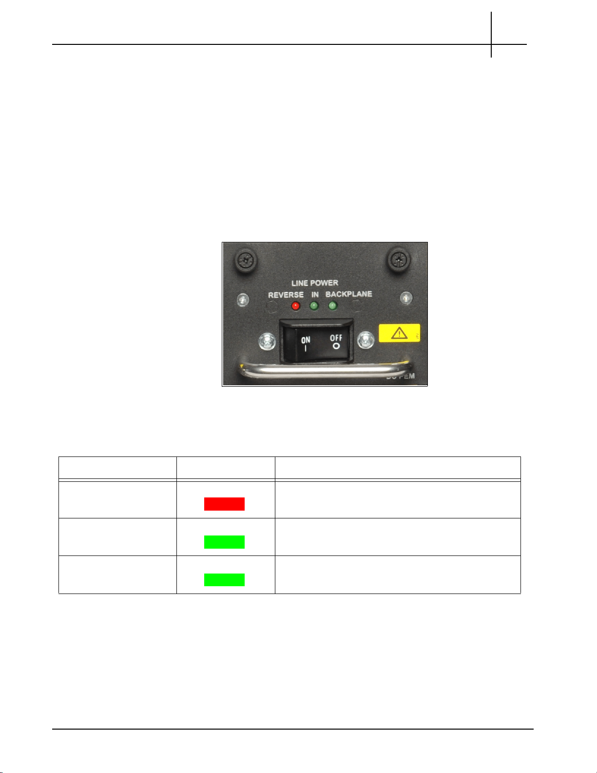
Figure 2.4 displays the DC Front Panel PEM LEDs and the ON and OFF switch.
abling will use 12AWG cable or
2
Figure 2.4 - DC PEM Front Panel LEDs and ON/OFF Switch
Table 2.3 describes the DC PEM LED indicators.
Table 2.3 - DC PEM LED Indicators
LED LED Color Description
Line Power Reverse RED Indicates the connected power is reversed. Do not
swit
ch on the breaker while this LED is on.
Line Power In GREEN Indicates the power is connected properly.
Line Power Backplane GREEN Indicates the power module is sending power from the
ckp
lane.
ba
G10 Hardware Maintenance Guide 7.13.2 27
Page 28
Rev. 002-140228
G10 Front View
G10 Rear View
Tektronix Communications | For Licensed Users | Unauthorized Duplication and Distribution Prohibited
AC PEMs
Chassis Subsystem
Figure 2.5 shows the G10 AC PEMs front view and rear view. Both A and B side power
modules operate within the specifications listed in Power and Ground Requirements. Refer to
Maintenance Guidelines for replacement details.
2
Figure 2.5 - G10 AC PEMs
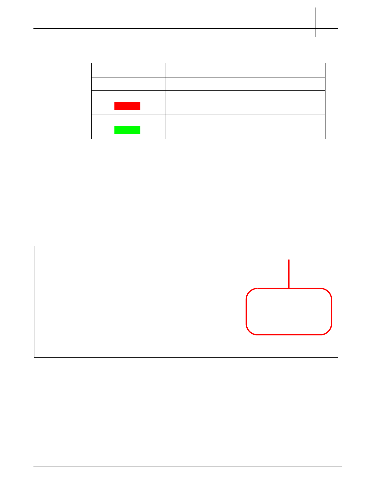
Front Panel LEDs
Figure 2.6 displays the AC Front Panel PEM LED.
Figure 2.6 - AC PEM Front Panel LED
G10 Hardware Maintenance Guide 7.13.2 28
Page 29
Rev. 002-140228
Front Fan Tray
Tektronix Communications | For Licensed Users | Unauthorized Duplication and Distribution Prohibited
FAN TRAYS
Chassis Subsystem
Table 2.3 displays the AC PEM LED indicators.
Table 2.4 - AC PEM LED Indicators
LED Color Description
OFF Power is disconnected.
RED Power supply is in a failed state.
GREEN The power is connected correctly.
The Chassis subsystem supports two fan trays in a push/pull configuration:
One fan tray is accessible from the front of the chassis and contains the replaceable
air filter.
2
The other fan tray is located in the rear of the chassis.
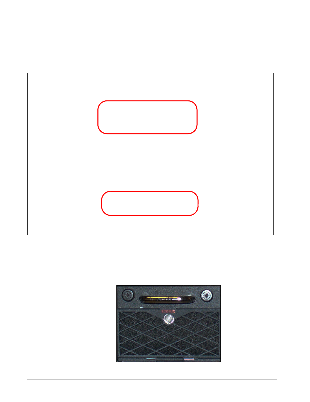
Figure 2.7 displays the front fan tray. Refer to Replacing the Fan Tray and Replacing G10
Chassis Air Filters for replacement details.
Figure 2.7 - Front Fan Tray
G10 Hardware Maintenance Guide 7.13.2 29
Page 30
Rev. 002-140228
Front ESD
Rear ESD
Tektronix Communications | For Licensed Users | Unauthorized Duplication and Distribution Prohibited
ELECTRO-STATIC DISCHARGE POINTS
The Electro-Static Discharge (ESD) points are locations where you can plug an ESD wrist
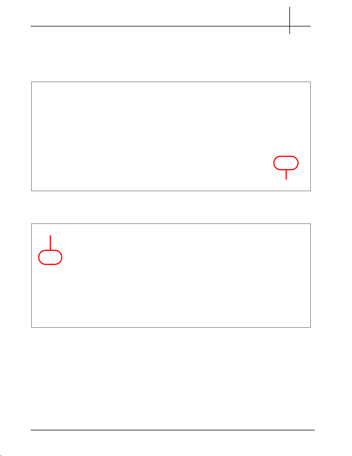
strap to the chassis to prevent electrical dama ge w hen yo u ha nd le the bo a rd s. Figure 2.8
displays the front ESD point.
Chassis Subsystem
2
Figure 2.8 - Front ESD Point
Figure 2.9 displays the rear ESD point.
Figure 2.9 - Rear ESD Point
G10 Hardware Maintenance Guide 7.13.2 30
Page 31

User Documentation
OVERVIEW
Tektronix Communications | For Licensed Users | Unauthorized Duplication and Distribution Prohibited
Blades and RTMs
The GeoProbe G10 is a modular device consisting of blades, Rear Transition Modules
(RTMs), and other hardware components that allow minimal risk and dependency on other
hardware devices. The probe is scalable and includes user-plane monitoring with high
IP traffic networks.
This chapter contains the following sections:
Iris Interface Cards and associated RTMs:
- IIC200 and SRM200 RTM
- IIC100 and SRM100 RTM and TRM100 RTM
Applications Blade and associated RTMs
- IAP320/IAP200 and PRM300 RTM/PRM200 RTM
- IAP100 and PRM100 RTM or SSD-3400 RTM
10G Interconnect Card (for Deep Packet Classification)
G10 Hardware Maintenance Guide 7.13.2 31
Page 32

Rev. 002-140228
CAB100 Carrier Blade
IIC LEDs
LPC200 AMC or LPC100 AMC FPC200 AMC or FPC100 AMC
Tektronix Communications | For Licensed Users | Unauthorized Duplication and Distribution Prohibited
IRIS INTERFACE CARD
The Iris Interface Card (IIC) ships with two Advanced Mezzanine Cards (AMCs) mounted in
the ATCA carrier blade (CAB100). The CAB100 is used to provide connectivity between the
AMC cards and the ATCA backplane. It also provides management interfaces for the AMCs
and the ATCA shelf management modules (ShMM), which are located on the back of the
probe.
Iris currently supports two IICs:
IIC200 (CAB100 + LPC200 AMC + FPC200 AMC)
IIC100 (CAB100 + LPC100 AMC + FPC100 AMC)
Blades and RTMs
3
Figure 3.1 - G10 IIC100
IIC LEDs
A total of four LEDs are visible from the left side of the IIC100 or IIC200 front panel that are
part of the CAB100 carrier blade (see Figure 3.2).
Figure 3.2 - IIC100 or IIC200 Front Panel LEDs
G10 Hardware Maintenance Guide 7.13.2 32
Page 33

Rev. 002-140228
Tektronix Communications | For Licensed Users | Unauthorized Duplication and Distribution Prohibited
Table 3.1 describes the IIC LEDs.
Table 3.1 - IIC LEDs
LED LED Color Description
H/S BLUE Hot Swap Indicator which indicates when it
SOLID BLUE—The module is in standby mode and can be safely
extracted.
Off—The module is operational and it is unsafe to extract it.
BLINKING BLUE—The module is in transition between standby mode
and operational mode.
Note: When either AMC needs to be removed, you must power down and
remove the entire IIC
blade first.
Refer to Iris Interface Card (IIC100 or
IIC200) and LPC and FPC AMCs (IIC100 or IIC200) for removal/
replacement information.
OOS RED Indicates the device is out of service.
SOLID RED—The board is out of service.
Blades and RTMs
is safe to remove the module.
3
OFF—No errors.
+ GREEN Indicates the health of the device.
SOLID GREEN—Out of Service.
OFF—No errors.
RTM SAS GREEN Green LED indicates status of the SAS RTM.
SOLID GREEN—No errors.
OFF—Fault condition.
G10 Hardware Maintenance Guide 7.13.2 33
Page 34

Rev. 002-140228
LPC200 AMC FPC200 AMC
Iris Interface Card (IIC200)
IIC
LEDs
Tektronix Communications | For Licensed Users | Unauthorized Duplication and Distribution Prohibited
IIC200
Blades and RTMs
The Iris Interface Card (IIC200) consists of the following components (Figure 3.3):
AMC ATCA carrier card (CAB100)
FPC200 AMC
LPC200 AMC
3
Figure 3.3 - G10 IIC200
IIC200 LEDs
The four LEDs visible from the left side of the IIC200 front panel are part of th e CAB100 carrier
blade (Figure 3.3). Refer to the IIC LEDs section for details.
G10 Hardware Maintenance Guide 7.13.2 34
Page 35

Rev. 002-140228
FPC200 AMC
Tektronix Communications | For Licensed Users | Unauthorized Duplication and Distribution Prohibited
FPC200 AMC
Blades and RTMs
The FPC200 AMC is located on the right side of the IIC200 (Figure 3.4) and serves as the
main flow processor. The main components of the FPC200 AMC are:
Flow Network Processor—includes a multi-core network processing unit (NPU) to
provide optimum packet processing
Memory—includes 16 GB of DRAM
Two GbE channels—for control plane activity and a 10 Gbps fabric between the
IIC200 and Applications blade through the backplane
3
Figure 3.4 - G10 IIC200 - FPC200 AMC
DO NOT remove AMCs when the IIC is powered on; refer to LPC and FPC AMCs (IIC100 or
IIC200) for removal/replacement details. Call Tektronix Technical Support for any questions
about removing AMCs.
FPC200 AMC LEDs
Figure 3.5 shows the FPC200 AMC LEDs located on the front panel.
Figure 3.5 - FPC200 AMC LEDs
G10 Hardware Maintenance Guide 7.13.2 35
Page 36

Rev. 002-140228
Tektronix Communications | For Licensed Users | Unauthorized Duplication and Distribution Prohibited
LED LED Color Description
Table 3.2 displays the LED indicators of the FPC200 AMC.
Table 3.2 - FPC200 AMC LEDs
Blades and RTMs
3
+ GREEN
GbE A GREEN or
AMBER
GbE B GREEN or
AMBER
CPU GREEN
Indicates the health of the device.
SOLID GREEN—No errors.
OFF—Out of service.
Indicates link status and activity for Gigabit Ethernet A connection
to carrier blade.
GREEN—The link is up.
BLINKING AMBER/GREEN—Link activity.
Indicates link status and activity for Gigabit Ethernet B connection
to carrier blade.
GREEN—The link is up.
BLINKING AMBER/GREEN—Link activity.
Indicates health and status of the processor.
GREEN—The processor has normal functions.
RS 232 COM Not Used.
Hot Sw
ap BLUE
Hot Swap Indicator which indicates when it is safe to remove the
module.
SOLID BLUE—The module is in standby mode and can be
safely extracted.
OFF—The module is operational, and it is unsafe to extract it.
BLINKING BLUE—The module is in transition between standby
mode and operational mode.
Note: W
hen this board needs to be removed, you will be remov
ing
the entire IIC200. Refer to Iris Interface Card (IIC100 or IIC200) for
more information.
G10 Hardware Maintenance Guide 7.13.2 36
Page 37

Rev. 002-140228
LPC200 AMC
1/10 GbE Port 5 and 6
1 GbE Port 1 and 2
1 GbE Port 3 and 4
1/10 GbE Port 7 and 8
Tektronix Communications | For Licensed Users | Unauthorized Duplication and Distribution Prohibited
LPC200 AMC
Blades and RTMs
The LPC200 AMC (Figure 3.6) is located on the left side of the IIC100 and provides 1G and
10G Ethernet connections on front panel. The
- Optical or electrical Ethernet links
- LC type optical ports provided by Small Form-Factor Pluggable (SFP) transceiver
. R
modules
efer to the SFP Reference appendix for details.
Ethernet connections support:
3
DO NOT remove AMCs when the IIC200 is powered on; refer to LPC and FPC AMCs
(IIC100 or IIC200) for removal/replacement details. Call Tektronix Technical Support for any
questions about removing AMCs.
LPC200 AMC Connectors
Figure 3.7 displays the LPC200 AMC connectors. The LPC200 AMC supports eight ports ,
four that support 1G Ethernet traffic, and four th
Figure 3.6 - G10 IIC200 - LPC200 AMC
at support either 10G or 1G traffic.
Figure 3.7 - LPC200 AMC Connectors
G10 Hardware Maintenance Guide 7.13.2 37
Page 38

Rev. 002-140228
1/10 GbE Port 5 and 6
Activity and Link LED
Health
LED
Hot Swap
LED
1 GbE Port 1 and 2
Activity and Link LED
1 GbE Port 3 and 4
Activity and Link LED
1/10 GbE Port 7 and 8
Activity and Link LED
Tektronix Communications | For Licensed Users | Unauthorized Duplication and Distribution Prohibited
Table 3.3 describes the LPC200 AMC connectors.
Table 3.3 - LPC200 AMC Connectors
LED Description
Blades and RTMs
3
1 GbE Ports 1–4
1/10 GbE Ports 5–8
LPC200 AMC LEDs
Figure 3.8 displays the LPC100 AMC LEDs.
Support 1G Ethernet traffic
Support copper or fiber SFP/SFP+s
Support 1G or 10G Ethernet traffic
Support fiber SFP/SFP+s
Figure 3.8 - LPC200 AMC LEDs
Table 3.4 describes the LPC200 AMC LEDs.
Table 3.4 - LPC200 AMC LEDs
LED LED Color Description
Hot Swap BLUE Hot Swap Indicator that indicates when it is safe to remove the
u
le.
mod
SOLID BLUE = The module is in standby mode and can be
safely extracted.
Off = The module is operational, and it is unsafe to extract it.
BLINKING BLUE = The module is in transition between
standby mode and operational mode.
+ GREEN Indicates the health of the device.
GREEN = No errors.
OFF = Out of service.
G10 Hardware Maintenance Guide 7.13.2 38
Page 39

Rev. 002-140228
Tektronix Communications | For Licensed Users | Unauthorized Duplication and Distribution Prohibited
D LED Color Description
LE
Table 3.4 - LPC200 AMC LEDs (Continued)
Blades and RTMs
3
1 GbE Port 1-4
LNK
1 GbE Port 1-4
ACT
1/10 GbE LNK GREEN or
GREEN GbE Port Link Status Indicator
GREEN = The link is up.
YELLOW GbE Por
YELLOW = Activity
t Activity Status Indicator
XGE port link status indicator
AMBER
AMBER = The 10G Link is up.
GREEN = The 1G link is up.
1/10 GbE ACT YELLOW XGE port activity status indicator
YELLOW = Activity
IIC200 RTMs
The IIC200 supports the following RTM configuration options for deployment:
IIC200 and the SRM200 RTM
IIC200 and the TRM100 RTM (to support eHRPD Monitoring)
SRM200 RTM
The SRM200 RTM connects to the back of the G10 chassis in the upper slot location. It
performs the following functions (Figure 3.9):
Communicates the board’s health and configuration status to the IIC200
Provides two Gigabit Ethernet links for connecti vity to controller enclosure
Sends and receives data to the disk array storage subsystem
G10 Hardware Maintenance Guide 7.13.2 39
Page 40

Rev. 002-140228
SRM200 RTM
GbE1 and GbE2
XLink 1-4
SAS Connectors
SysClk (not used)
Tektronix Communications | For Licensed Users | Unauthorized Duplication and Distribution Prohibited
Figure 3.9 - SRM200 RTM
SRM200 RTM Connectors
Figure 3.10 displays the SRM200 RTM connectors.
Blades and RTMs
3
GbE1–GbE 2 RJ45 Gigabit Ethernet connectors to the second controller
SysClk 1–2 Not used.
XLink 1–4 10G Ethernet SFP connections used in multi-cage
SAS 1–2 Provides connectivity to the exte
Figure 3.10 - SRM200 RTM Connectors
Table 3.5 describes the SRM200 RTM connectors.
Table 3.5 - SRM200 RTM Connectors
Connector Description
n
closure.
e
igurations for intercage communications.
conf
rnal disk array storage system.
G10 Hardware Maintenance Guide 7.13.2 40
Page 41

Rev. 002-140228
Hot Swap
LED
+ LED
Gb Ethernet LEDs
XLink 1-4 Lnk and Act LEDs
SAS LEDs
Tektronix Communications | For Licensed Users | Unauthorized Duplication and Distribution Prohibited
LED LED Color Description
SRM200 RTM LEDs
Figure 3.11 displays the SRM200 RTM LEDs.
Figure 3.11 - SRM200 RTM Rear Panel LEDs
Table 3.6 describes the SRM200 RTM LED indicators.
Table 3.6 - SRM200 RTM LED Indicators
Blades and RTMs
3
Hot Swap BLUE Indicates when it is safe to re
BLUE—module is in standby mode and can be safely
move the
SRM200 RTM.
extracted.
OFF—module is operational and it is unsafe to extract it.
BLINKING BLUE—module is in transition between
standby mode and operational mode.
+ (Health) GREEN or RED Indicates the health of the SRM200 RTM.
GREEN—no errors.
RED—an error occurred.
OFF—the board is not powered on.
Gb Ethernet LEDs GREEN Indicates Gigabit Ethernet link and activity.
BLINKING GREEN—Ethernet Activity is occurring.
SOLID GREEN—Ethernet Link is established.
OFF—no Ethernet Link is established.
XLink 1–4 Lnk LEDs GREEN Indicates 10 Gigabit Ethernet link status.
GREEN = Ethernet link is trained at 10 Gb/s speed.
OFF = no Ethernet link established
G10 Hardware Maintenance Guide 7.13.2 41
Page 42

Rev. 002-140228
LPC100 AMC
Iris Interface Card (IIC100)
IIC
LEDs
FPC100 AMC
Tektronix Communications | For Licensed Users | Unauthorized Duplication and Distribution Prohibited
Blades and RTMs
3
Table 3.6 - SRM200 RTM LED Indicato
rs (Continued)
LED LED Color Description
XLink 1–4 Act LEDs YELLOW Indicates 10 Gigabit Ethernet link and activity.
SOLID YELLOW = Ethernet link is trained, no activity.
BLINKING YELLOW = Ethernet activity occurring.
OFF = no Ethernet link established.
SAS LEDs GREEN or RED Indicates SAS link connectivity status.
GREEN—no errors, SAS link is established.
BLINKING GREEN—SAS activity occurring.
RED—an error occurred.
OFF—no SAS link is established.
IIC100
The Iris Interface Card (IIC100) consists of the following components (Figure 3.12):
ATCA carrier card (CAB100)
FPC100 AMC
LPC100 AMC
Figure 3.12 - G10 IIC100
G10 Hardware Maintenance Guide 7.13.2 42
Page 43

Rev. 002-140228
FPC100 AMC
Tektronix Communications | For Licensed Users | Unauthorized Duplication and Distribution Prohibited
FPC100 AMC
Blades and RTMs
The FPC100 AMC is located on the right side of the IIC100 (Figure 3.13) and serves as the
main flow processor. The main components of the FPC100 AMC are:
Flow Network Processor—includes a multi-core network processing unit (NPU) to
provide optimum packet processing
Memory—includes 4 GB or 8 GB of DRAM
Two GbE channels—for control plane activity and a 10 Gbps fabric between the
IIC100 and Applications blade through the backplane
The FPC100 AMC supports 4 GB or 8 GB of DRAM (new systems ship with 8 GB of DRAM).
GB FPC100 AMC can be replaced with the 8 GB FPC100 AMC in the field to support
The 4
Iris applications requiring additional DRAM. Contact Customer Support for details.
3
Figure 3.13 - G10 IIC100 - FPC100 AMC
DO NOT remove AMCs when the IIC is powered on; refer to LPC and FPC AMCs (IIC100 or
IIC200) for removal/replacement details. Call Tektronix Technical Support for any questions
about removing AMCs.
FPC100 AMC LEDs
Figure 3.14 shows the FPC100 AMC LEDs located on the front panel.
Figure 3.14 - FPC100 AMC Front Panel LEDs
G10 Hardware Maintenance Guide 7.13.2 43
Page 44

Rev. 002-140228
Tektronix Communications | For Licensed Users | Unauthorized Duplication and Distribution Prohibited
Table 3.7 displays the FPC100 AMC LEDs.
Table 3.7 - FPC100 AMC LEDs
LED/Connector LED Color Description
Blades and RTMs
3
+ GREEN
GbE A GREEN or
AMBER
GbE B GREEN or
AMBER
10GbE FAB GREEN or
AMBER
CPU AMBER
Indicates the health of the device.
SOLID GREEN—No errors.
OFF—Out of service.
Indicates link status and activity for Gigabit Ethernet A connection
to carrier blade.
GREEN—The link is up.
BLINKING AMBER—Link activity.
Indicates link status and activity for Gigabit Ethernet B connection
to carrier blade.
GREEN—The link is up.
BLINKING AMBER—Link activity.
10-Gigabit Ethernet Fabric.
Indicates status for Ethernet interface to the blade through the
backpla
GREEN—The link is up.
BLINKING AMBER—Link activity.
ne.
Indicates health and status of the processor.
AMBER—The processor has normal functions.
RS 232 COM Not Used.
Hot Swap BLUE
Hot Swap Indicator that indicates when it is safe to remove the
module.
SOLID BLUE—The module is in standby mode and can be
safely extracted.
OFF—The module is operational, and it is unsafe to extract it.
BLINKING BLUE—The module is in transition between
standby mode and operational mode.
Note: When this board needs to be remov
the entire Iris Interface Controller blade. Refer to Iris Interface
Card (IIC100 or IIC200) for more information.
e
d, you will be removing
G10 Hardware Maintenance Guide 7.13.2 44
Page 45

Rev. 002-140228
LPC100 AMC
GbE Port
Activity LED
GbE Port
Link LED
Health
LED
Hot Swap
LED
Tektronix Communications | For Licensed Users | Unauthorized Duplication and Distribution Prohibited
LPC100 AMC
Blades and RTMs
The LPC100 AMC (Figure 3.15) is located on the lef t side of the IIC100 and provides eight 1G
Ethernet connections on front panel. The Ethe
- Optical or electrical Ethernet links
- LC type optical ports provided by Small Form-Factor Pluggable (SFP) transceiver
. R
modules
efer to the SFP Reference appendix for details.
rnet connections support:
3
Figure 3.15 - G10 IIC - LPC100 AMC
DO NOT remove AMCs when the IIC is powered on; refer to LPC and FPC AMCs (IIC100 or
IIC200) for removal/replacement details. Call Tektronix Technical Support for any questions
about removing AMCs.
LPC100 AMC LEDs
Figure 3.16 displays the LPC100 AMC LEDs.
Figure 3.16 - LPC100 AMC LEDs
G10 Hardware Maintenance Guide 7.13.2 45
Page 46

Rev. 002-140228
Tektronix Communications | For Licensed Users | Unauthorized Duplication and Distribution Prohibited
Blades and RTMs
Table 3.8 describes the LPC100 AMC LEDs.
Table 3.8 - LPC100 AMC LEDs
LED LED Color Description
Hot Swap BLUE Hot Swap Indicator which indicates when it is safe to remove the
le.
modu
SOLID BLUE—The module is in standby mode and can be safely
extracted.
Off—The module is operational, and it is unsafe to extract it.
BLINKING BLUE—The module is in transition between standby
mode and operational mode.
+ GREEN Indicates the health of the device.
GREEN—No errors.
OFF—Out of service.
ACT YELLOW GbE Port Activity Status Indicator
3
YELLOW = Activity.
LNK GREEN GbE Port Link Status Indicator
GREEN = The link is up.
IIC100 RTMs
The IIC100 supports the following RTM configuration options for deployment:
8x1G probe—IIC100 and the SRM100 RTM
Mixed 1G and 10G probe—IIC100 and the TRM100 RTM
SRM100 RTM
The SRM100 RTM is used in 8X1G installations and connects to the back of the GeoProbe
G10 chassis in the upper slot location. It performs the following functions (Figure 3.17):
Communicates the board’s health and configuration status to the IIC100
Provides two Gigabit Ethernet links for connectivity to second controller enclosure
Sends and receives data to the disk array storage subsystem
G10 Hardware Maintenance Guide 7.13.2 46
Page 47

Rev. 002-140228
SRM100 RTM
GbE1 and GbE2
XLink 1-4 (not used)
SAS Connectors
Tektronix Communications | For Licensed Users | Unauthorized Duplication and Distribution Prohibited
Figure 3.17 - SRM100 RTM
SRM100 RTM Connectors
Figure 3.18 displays the SRM100 RTM connectors.
Blades and RTMs
3
Figure 3.18 - SRM100 RTM Connectors
Table 3.9 describes the SRM100 RTM connectors.
Table 3.9 - SRM100 RTM Connectors
Connector Description
GbE1–GbE 2 These connectors are the RJ-45 Gigabit Ethernet connectors to
e s
econd controller enclosure.
th
SysClk 1–2 These connectors are not used.
XLink 1–4 These connectors are not used.
SAS 1–2 This connector provides connectivity to the ex
storage system.
ternal disk array
G10 Hardware Maintenance Guide 7.13.2 47
Page 48

Rev. 002-140228
Hot Swap
LED
+ LED
Gb Ethernet LEDs
XLink 1-4 LEDs (not used)
SAS LEDs
Tektronix Communications | For Licensed Users | Unauthorized Duplication and Distribution Prohibited
LED LED Color Description
SRM100 RTM LEDs
Figure 3.19 displays the SRM100 RTM LEDs.
Figure 3.19 - SRM100 RTM Rear Panel LEDs
Table 3.10 describes the SRM100 RTM LED indicators.
Table 3.10 - SRM100 RTM LED Indicators
Blades and RTMs
3
remov
Hot Swap BLUE Indicates when it is safe to
BLUE—The module is in standby mode and can be safely
e the SRM100.
extracted.
OFF—The module is operational, and it is unsafe to extract
it.
BLINKING BLUE—The module is in transition between
standby mode and operational mode.
+ (Health) GREEN or RED Indicates the health of the SRM100 RTM.
GREEN—No errors.
RED—An error occurred.
OFF—The board is not powered on.
Gb Ethernet LEDs GREEN Indicates Gigabit Ethernet link and activity.
BLINKING GREEN—Ethernet activity is occurring.
SOLID GREEN—The Ethernet link is established.
OFF—No Ethernet link is established.
XLink 1–4 LEDs These LEDs are not used.
SAS LEDs GREEN or RED Indicates SAS link connectivity status.
GREEN—No errors; SAS link is established.
RED—An error occurred.
OFF—No SAS link is established.
G10 Hardware Maintenance Guide 7.13.2 48
Page 49

Rev. 002-140228
TRM100 RTM
10GbE Connectors (4)
Sys Clock
SAS Connectors (2)
GbE Connectors (2)
Tektronix Communications | For Licensed Users | Unauthorized Duplication and Distribution Prohibited
TRM100 RTM
Blades and RTMs
The TRM100 RTM is used in the following configurations:
Mixed 1G and 10G Ethernet probe installations with IIC100
Mixed 1G and 10G Ethernet probe installations with IIC200 supporting eHRPD
monitoring
The TRM100 RTM connects to the back of the GeoProbe G10 chassis in the upper slot
location
and performs the following functions:
Communicates the board’s health and configuration status to its counterpart IPMC on
the IIC100 or IIC200
Serves as the store-to-disk interface to the disk array with 10Gb Ethernet capability.
Provides four 10G optical inputs for monitored links when used with IIC100. (When
used with IIC200, no 10G monitored links are connected to the TRM100 RTM; all 10G
monitored traffic is connected to the IIC200 [LPC200].
Figure 3.20 displays the TRM100 RTM.
3
Figure 3.20 - TRM100 RTM
TRM100 RTM Connectors
Figure 3.21 displays the TRM100 RTM connectors.
Figure 3.21 - TRM100 RTM Connectors
G10 Hardware Maintenance Guide 7.13.2 49
Page 50

Rev. 002-140228
Tektronix Communications | For Licensed Users | Unauthorized Duplication and Distribution Prohibited
Table 3.11 describes the TRM100 RTM connectors.
Table 3.11 - TRM100 RTM Connectors
Connector Description
10GbE (4) 10 GbE SFP+ (fiber) connectors
When used with IIC100, these ports provide inputs for monitored links or intercage
communications for multiprobe configurations.
When used with the IIC200, these connectors are not used.
GbE (2) Two Gb Ethernet connections
Blades and RTMs
3
Provide
s connections to storage controller(s).
SysClk (2) System Clock Connectors.
For standalone G10 configurations, these can be used for external SYS CLK
connections.
For the Media Probe configuration, thes e po rts are used for chas sis- to -ch a ssis
timing distribution.
Refer to SysClk Termination Switch for more details.
SAS (2) SAS Connectors
Provides connections to external storage subsystem.
Table 3.12 shows the RJ45 pin assignments for the SYSCLK
Table 3.12 - SYSCLK RJ45 Pin Assignments
Pin Description
1 CARR_CLK1A+
2 CARR_CLK1A3 CARR_CLK2A+
connectors.
4 no connect
5 no connect
6 CARR_CLK2A7 CARR_CLK3A+
8 CARR_CLK3A-
G10 Hardware Maintenance Guide 7.13.2 50
Page 51

Rev. 002-140228
SYSCLK Termination
Switch
Tektronix Communications | For Licensed Users | Unauthorized Duplication and Distribution Prohibited
Blades and RTMs
SysClk Termination Switch
Some G10 probe configurations require the use
of the SYSCLK 1 and SYSCLK 2
connectors, and you must change settings on the SYSCLK Termination switch. The
TRM100 provides access to the SYSCLK termination switch behind a faceplate
(Figure 3.22).
Figure 3.22 - TRM100 SYSCLK Termination Switch
3
ou need to set the SYSCLK DIP switch settings in the following
Y
G10 standalone chassis using external SYSCLK—determine if the SYSCLK signal is
scenarios:
terminated or bridged at customer site and set the DIP switches accordingly.
Media probe two-chassis configuration—the Primary and Expansion Chassis must
use the TERMINATED setting on ALL THREE SYSCLK Termination Switches.
Table 3.13 shows the SYSCLK Dip Switch Settings. All eight DIP swi
same setting at any given time; all switches must be se
t to the up position or all switches must
tches must be set to the
be set to the down position.
Table 3.13 - SYSCLK Termination Switch Dip Switch Settings
Setting Description
Up (open/off)
BRIDGED
Down (closed/on)
TERMINATED
SYSCLK is BRIDGED (not terminated). This is
de
fault switch setting.
SYSCLK is TERMINATED with a 200 Ω pu
resistor.
0
ALL TRM10
RTM SYSCLK switches on the Media
Probe Primary and Expansion chassis must use this
setting.
the
ll-down
G10 Hardware Maintenance Guide 7.13.2 51
Page 52

Rev. 002-140228
GbE Activity LEDs
Hot Swap
LED
10GbE LNK and ACT
Status LEDs
MMC Health
Status LED
SAS LEDs (2)
Tektronix Communications | For Licensed Users | Unauthorized Duplication and Distribution Prohibited
TRM100 RTM LEDs
Figure 3.23 displays the TRM100 RTM LEDs.
Figure 3.23 - TRM100 RTM LEDs
Table 3.14 describ es th e TRM100 RTM LEDs.
Table 3.14 - TRM100 RTM LED Indicators
Blades and RTMs
3
Connector/LED LED Color Description
Hot Swap BLUE
Indicates when it is safe to remove the module.
SOLID BLUE—module is in standby mode and can
be safely extracted.
OFF—module is operational and it is unsafe to
extract it.
BLINKING BLUE—module is in transition between
standby mode and operational mode.
+ GREEN or RED
LNK (10GbE) GREEN
MMC health LED.
GREEN—no errors.
RED—error occurred.
OFF—board is not powered on.
Four 10-Gb link LEDs; one for each of the SFP+
modules. These indicate the status of the port
connectivity.
GREEN—10-Gb link is up.
OFF—no link established.
ACT (10GbE) YELLOW
Four 10-Gb activity LEDs; one for each of the SFP+
modules. These indicate the status of the traf fic ru nning
over the connection.
BLINKING YELLOW—10-Gb Ethernet activity
occurring.
OFF—no 10-Gb Ethernet activity.
G10 Hardware Maintenance Guide 7.13.2 52
Page 53

Rev. 002-140228
Tektronix Communications | For Licensed Users | Unauthorized Duplication and Distribution Prohibited
Table 3.14 - TRM100 RTM LED Indicators (Continued)
Blades and RTMs
3
Connect
or/LED LED Color Description
GbE Activity GREEN
ACT (SAS) GREEN or RED
APPLICATIONS BLADE
The Applications Blade provides the following functions for the G10 probe:
Performs analysis, correlation, and pr ocessing functions
Controls the OS for GeoProbe G10
Gb Ethernet Activity LEDs which indicate the status of
the traffic running over the connection.
BLINKING GREEN—Ethernet activity occurring.
SOLID GREEN—Ethernet link is up.
OFF—no Ethernet link established.
Indicates SAS activity.
GREEN—no errors, SAS link is up.
RED—error occurred.
OFF—no SAS link established.
Provides the Ethernet connection to customer LAN
Enables S2D functionality (LT and ST)
Iris currently supports the following applications blades:
IAP320/IAP200
IAP100
G10 Hardware Maintenance Guide 7.13.2 53
Page 54

Rev. 002-140228
IAP320
IAP200
Tektronix Communications | For Licensed Users | Unauthorized Duplication and Distribution Prohibited
IAP320/IAP200
Blade Description
Blades and RTMs
3
The IAP320 and IAP200 connect to the front of the G10 chassis in Slot 1 (bottom slot). The
blades vary based on the configurations described in Table 3.15.
Table 3.15 - IAP320/IAP200
IAP320
IAP200
Two 10-core Intel Xeon processors (1.9 GHz)
192 GB DDR3 memory
Supports PRM300 RTM
Two 6-core Intel Xeon Processors (2.0 GHz)
96 GB or 112 GB DDR3 memory. New systems ship with 112 GB
DRAM. A G10 can be upgraded to the 112 GB IAP200 to support
Iris applications re
quiring additional DRAM. Contact Customer
Support for details.
Supports PRM200 RTM
Figure 3.24 shows an example of the applications blade.
Figure 3.24 - G10 IAP320 and IAP200
G10 Hardware Maintenance Guide 7.13.2 54
Page 55

Rev. 002-140228
OOS +
F1-F2
H/S
ETH
Link
ETH
Activity
B1-B2
U1-U4
Tektronix Communications | For Licensed Users | Unauthorized Duplication and Distribution Prohibited
IAP320
IAP320 LEDs
Blades and RTMs
3
The IAP320 indicators provide status and error information. The L ED indicators are located on
the front panel of the board. Figure 3.25 displays the front panel LEDs of the IAP320.
Figure 3.25 - IAP320 Front Panel LEDs
Table 3.16 displays th e IAP3 20 LED ind ica tors .
Table 3.16 - IAP320 LED Indicators
LED LED Color Description
OOS RED or AMBER Indicates out of service status.
RED or AMBER—The CPM is out of service.
OFF—Normal operation.
Health (+) GREEN or RED Indicates the health of the RTM.
GREEN—No errors.
RED—An error occurred.
OFF—The board is not powered on.
ETH Link LED GREEN
ETH Activity LED YELLOW
Indicates status of Ethernet connector.
GREEN—The link is available.
OFF—No link established.
Indicates the status of Ethernet traffic on the connection.
F1-F2 (L) GREEN
YELLOW—Ethernet activity occurring.
OFF—No Ethernet activity occurring.
Fabric Interface Link Indicator
GREEN = The Ethernet link is up.
OFF = No link established.
G10 Hardware Maintenance Guide 7.13.2 55
Page 56

Rev. 002-140228
Tektronix Communications | For Licensed Users | Unauthorized Duplication and Distribution Prohibited
Blades and RTMs
3
Table 3.16 - IAP320 LED Indicators
(Continued)
LED LED Color Description
F1-F2 (A) YELLOW Fabric Interface Activity Indicator
YELLOW—Ethernet activity occurring.
OFF—No Ethernet activity occurring.
B1-B2 (L) GREEN or YELLOW Base Interface Link Indicator
GREEN = The Ethernet link is up at 1 Gb speed.
YELLOW = The Ethernet link is up at 100M speed.
OFF = No link established.
B1-B2 (A) YELLOW
Base Interface Activity Indicator
YELLOW—Ethernet activity occurring.
OFF—No Ethernet activity occurring.
U1-U4 Not used.
H/S BLUE Indicates blade state machine status and hot swap status.
During blade installation:
SOLID BLUE—The on-board IPMC powers up.
BLINKING BLUE—The blade communicates with shelf
manager.
OFF—The blade is active.
During blade removal:
SOLID BLUE—The blade is in standby mode and can be
safely extracted.
OFF—The blade is operational, and it is unsafe to extract
it.
BLINKING BLUE—The module is in a transition between
standby mode and operational mode.
G10 Hardware Maintenance Guide 7.13.2 56
Page 57

Rev. 002-140228
ETH
USB Ports
Serial Console Port
Tektronix Communications | For Licensed Users | Unauthorized Duplication and Distribution Prohibited
IAP320 Connectors
Figure 3.26 displays the IAP320 connectors.
Figure 3.26 - IAP320 Connectors
Table 3.17 prov ide s descr ipt i on s of the IAP3 20 con ne ct or s.
Blades and RTMs
3
Table 3.17 - IAP320 Connectors
Connector Description
ETH Connector Used during initial probe configuration; not used during normal
e operation.
ob
pr
Serial Console Port Enables an RJ-45 cable to connect to an external computer to
splay and interact with the CPM’s software. In order to
di
communicate with the CPM, the terminal emulator on the
external computer must match the default settings for the CPM
serial port:
28800 bps
no parity
8 data bits
1 stop bit
no flow control
For best display results, the terminal should be set to 80
columns by 25 lines.
USB 1–2 The se co nn e cto rs are a standard USB 2.0 used for service and
a
intenance.
m
G10 Hardware Maintenance Guide 7.13.2 57
Page 58

Rev. 002-140228
OOS IS ATN
H/S
ETH
Link
ETH
Activity
Tektronix Communications | For Licensed Users | Unauthorized Duplication and Distribution Prohibited
IAP200
IAP200 LEDs
Blades and RTMs
3
The IAP200 indicators provide status and error information. The L ED indicators are located on
the front panel of the board. Figure 3.25 displays the front panel LEDs of the IAP200.
Figure 3.27 - IAP200 Front Panel LEDs
Table 3.16 displays th e IAP2 00 LED ind ica tors .
Table 3.18 - IAP200 LED Indicators
LED LED Color Description
OOS RED or AMBER Indicates out of service status.
RED or AMBER—The CPM is out of service.
OFF—Normal operation.
IS GREEN Indicates Payload Power status.
GREEN—Payload power has been has been enabled by
the IPMC. Note that this LED indicates the payload
power status both in the early power state an d the normal
blade operation.
OFF—Payload power is disabled.
ATN Not Used.
ETH Link LED GREEN
Indicates status of Ethernet connector.
GREEN—The link is available.
OFF—No link established.
ETH Activity LED YELLOW
G10 Hardware Maintenance Guide 7.13.2 58
Indicates the status of Ethernet traffic on the connection.
YELLOW—Ethernet activity occurring.
OFF—No Ethernet activity occurring.
Page 59

Rev. 002-140228
ETH
USB Ports
Serial Console Port
Tektronix Communications | For Licensed Users | Unauthorized Duplication and Distribution Prohibited
Table 3.18 - IAP200 LED Indicators (Continued)
LED LED Color Description
U1-U3 Not used.
Blades and RTMs
3
H/S BLUE Indicates blade state machine st
During blade installation:
SOLID BLUE—The on-board IPMC powers up.
BLINKING BLUE—The blade communicates with shelf
manager.
OFF—The blade is active.
During blade removal:
SOLID BLUE—The blade is in standby mode and can be
safely extracted.
OFF—The blade is operational, and it is unsafe to extract
it.
BLINKING BLUE—The module is in a transition between
standby mode and operational mode.
IAP200 Connectors
Figure 3.26 displays the IAP200 connectors.
atus an
d hot swap status.
Figure 3.28 - IAP200 Connectors
G10 Hardware Maintenance Guide 7.13.2 59
Page 60

Rev. 002-140228
Tektronix Communications | For Licensed Users | Unauthorized Duplication and Distribution Prohibited
Blades and RTMs
Table 3.17 prov ide s descr ipt i on s of the IAP2 00 con ne ct or s.
Table 3.19 - IAP200 Connectors
Connector Description
ETH Connector Used during initial probe configuration; not used during normal
ob
e operation.
pr
Serial Console Port Enables an RJ-45 cable to connect to an external computer to
splay and interact with the CPM’s software. In order to
di
communicate with the CPM, the terminal emulator on the
external computer must match the default settings for the CPM
serial port:
28800 bps
no parity
8 data bits
1 stop bit
no flow control
3
USB 1–2 The se co nn e cto rs are a standard USB 2.0 used for service and
PRM300 RTM/PRM200 RTM
The IAP320 supports the PRM300 RTM; and the IAP200 supports the PRM200 RTM. These
RTMs have the same connectors and LEDs.
The RTM provides additional connectivity opti ons an d a ha rd di sk us ed for the op e ra tin g
system. The R
functions:
Provides cable connections to the disk array
Provides hard drive for operating system
Includes an IPMC
TMs connect to the rear of the respective IAP. The RTM performs the following
For best display results, the terminal should be set to 80
columns by 25 lines.
a
intenance.
m
G10 Hardware Maintenance Guide 7.13.2 60
Page 61

Rev. 002-140228
Hot
Swap
LED
Health (+)
LED
Ethernet LNK and
ACT LEDs
SAS
Activity
LEDs
Tektronix Communications | For Licensed Users | Unauthorized Duplication and Distribution Prohibited
PRM300/PRM200 LEDs
Figure 3.29 displays the PRM200/PRM300.
Figure 3.29 - PRM300/PRM200 RTM
Figure 3.30 shows the RTM LED indicators.
Blades and RTMs
3
Figure 3.30 - PRM300/PRM200 LEDs
Table 3.20 describ es th e PRM 300 /PRM 2 00 LEDs.
Table 3.20 - PRM300/PRM200 RTM LEDs
LED LED Color Description
Hot Swap BLUE Hot Swap Indicator which indicates
when it
is safe to remove
the RTM.
SOLID BLUE— The blade is in standby mode and can be
safely extracted.
BLINKING BLUE—The module is in a transition between
standby mode and operational mode.
OFF—The blade is active; do not extract it.
Health (+) GREEN or RED Indicates the health of the PRM200 RTM.
G10 Hardware Maintenance Guide 7.13.2 61
GREEN—No errors.
RED—An error occurred.
OFF—The board is not powered on.
Page 62

Rev. 002-140228
ETH A
SAS Ports
ETH B
ETH C ETH D
Tektronix Communications | For Licensed Users | Unauthorized Duplication and Distribution Prohibited
LE
D LED Color Description
Table 3.20 - PRM300/PRM200 RTM LEDs (Continued)
Blades and RTMs
3
Ethernet ACT
LEDs
Ethernet LNK
LEDs
YELLOW I
GREEN,
AMBER, or RED
ndicates Ethernet link activity.
SOLID YELLOW = The Ethernet link is up; no activity.
BLINKING YELLOW = Ethernet activity occurring.
OFF = No Ethernet link established.
I
ndicates Ethernet link status.
GREEN = The Ethernet link is up at 10 Gb speed.
AMBER = The Ethernet link is up at 1 Gb speed.
RED = The Ethernet link is up at 100M speed.
OFF = No link established.
ACT (SAS) GREEN or RED SAS activity LED
Two SAS activity LEDs, one fo r each SAS port.
GREEN—No errors; SAS link is up.
RED—Error occurred.
OFF—No SAS link established.
PRM300/PRM200 Connectors
Figure 3.31 shows the RTM LED indicators.
Figure 3.31 - PRM300/PRM200 Connectors
Table 3.21 describ es th e PRM 300 /PRM 2 00 con nect or s .
Table 3.21 - PRM300/PRM200 Connectors
Connector Description
ETH A (Primary Interface) Primary 1G Ethernet LAN (uplink to server). Supports 10G/1G/100Mb;
rm
al usage is 1G/100Mb for OAM.
no
ETH B Redundant Primary 1G Ethernet LAN (uplink to server). Only used for
ndant Primary LAN configuration. Supports 10G/1G/100Mb; normal
redu
usage is 1G/100Mb for OAM.
G10 Hardware Maintenance Guide 7.13.2 62
Page 63

Rev. 002-140228
SAS AMC
IAP100
Tektronix Communications | For Licensed Users | Unauthorized Duplication and Distribution Prohibited
Blades and RTMs
3
Table 3.21 - PRM300/PRM200
Connector Description
ETH C Ethernet LAN used for inter-cage connection
ETH D
SAS Ports (two) Provides connectivity to storage subsystem.
Supports 10G/1G/100Mb; normal usage is 10G for inter -cage
communication.
Connectors (Continued)
IAP100
The IAP100 Applications Blade (Figure 3.32) consists of a quad-core Intel Core Processor
with 32 Gb of DDR3 memory. The IAP100 connects to the front of the G10 chassis in Slot 1
(bottom slot). An
store-to-disk (S2D) functionality. The blade suppor
interface that are PICMG 3.0 compliant and dual 10Gb Ethernet links for the Fabric interface
that are PICMG 3.1 (option 9 or 1) compliant. The IAP100 supports the PRM100 RTM or the
SSD-3400 RTM.
SAS AMC with two SAS ports provides connectivity to storage arrays for
ts dual 1Gb Ethernet links for the Base
in multicage configuration.
Figure 3.32 - G10 IAP100
G10 Hardware Maintenance Guide 7.13.2 63
Page 64

Rev. 002-140228
OOS PWR APP
H/S
Tektronix Communications | For Licensed Users | Unauthorized Duplication and Distribution Prohibited
IAP100 LEDs
Blades and RTMs
3
The IAP100 indicators provide status and error information. The L ED indicators are located on
the front panel of the board (Figure 3.33).
Figure 3.33 - IAP100 Front Panel LEDs
Table 3.22 displays th e IAP1 00 LED ind ica tors .
Table 3.22 - IAP100 LED Indicators
LED LED Color Description
e an
OOS RED or AMBER Indicates the device is out of servic
RED or AMBER—The CPM is out of service.
OFF—Normal operation.
d is controlled by the IPMC.
PWR GREEN Indicates whether the CPM power supplies are within a level of
toler
ance.
GREEN—All power supplies are good, and power has not been
removed.
OFF—The module is not powered on.
APP AMBER This LED is application defined and controlled by the IPMC. When the
LED is Ambe
r, it is controlled by the IPMC with application-defined
functionality.
H/S BLUE Hot Swap mode status; indicates when it is safe to remove the module.
SOLID BLUE— The module is in standby mode and can be safely
extracted.
OFF—The module is operational, and it is unsafe to extract it.
BLINKING BLUE—The module is in a transition between standby
mode and operational mode.
G10 Hardware Maintenance Guide 7.13.2 64
Page 65

Rev. 002-140228
Serial Console Port
ETH A
(Primary
Interface)
ETH B
(Not Used)
USB
Ports
SAS
Connectors
Tektronix Communications | For Licensed Users | Unauthorized Duplication and Distribution Prohibited
IAP100 Connectors
Figure 3.34 displays the IAP100 connectors.
Figure 3.34 - IAP100 Connectors
Table 3.23 prov ide s descr ipt i on s of the IAP1 00 con ne ct or s.
Table 3.23 - IAP100 Connectors
Blades and RTMs
3
Connector Description
Ethernet A Connector Provides the interface to connect to the customer LAN (Primary
te
rface).
In
Ethernet B Connector Not used.
Serial Console Port Enables an RJ-45 cable to connect to an external computer to
splay and interact with the CPM’s software. In order to
di
communicate with the CPM, the terminal emulator on the
external computer must match the default settings for the CPM
serial port:
115200 bps
no parity
8 data bits
1 stop bit
no flow control
For best display results, the terminal should be set to 80
column
s by 25 lines.
USB 1–2 Standard USB 2.0 used for service and maintenance.
SAS Connectors Part of the SAS AMC.
G10 Hardware Maintenance Guide 7.13.2 65
Page 66

Rev. 002-140228
SAS Connectors
ACT LED
OOS LED
Hot Swap LED
Tektronix Communications | For Licensed Users | Unauthorized Duplication and Distribution Prohibited
SAS AMC
Blades and RTMs
3
The SAS AMC on the IAP100 provides connectivity to the disk array via two SAS connectors.
Figure 3.35 displays the SAS AMC. Refer to SAS AMC (IAP100) for removal/replaceme nt
procedures.
Figure 3.35 - IAP100 SAS AMC Connectors
SAS AMC LEDs
Table 3.24 displays the SAS AMC LED indicators.
Table 3.24 - SAS AMC LEDs
LED LED Color Description
ACT YELLOW YELLOW—SAS activity on the device.
OOS RED or AMBER Indicates the device is out of service
options are:
RED or AMBER—The CPM is out of service.
OFF—Normal operation.
H/S BLUE Indicates when it is safe to remo
BLUE—The module is in standby mode and can b e safely extracted.
OFF—The module is operational, and it is unsafe to extract it.
BLINKING—The module is in a transition between standby mode
and operational mode.
an
ve the module. Valid options are:
d is controlled by the IPMC. V a lid
SAS AMC Connectors
The SAS AMC contains SAS Port 1 and SAS Port 2 that provide connectivity to the storage
G10 Hardware Maintenance Guide 7.13.2 66
enclosures.
Page 67

Rev. 002-140228
Tektronix Communications | For Licensed Users | Unauthorized Duplication and Distribution Prohibited
IAP100 RTMs
PRM100 RTM
Blades and RTMs
3
The IAP100 supports the following Rear Transition Modules (RTMs):
PRM100 RTM
SSD-3400 RTM
The PRM100 RTM connects to the rear of IAP100. The RTM works in conjunction with the
IAP100 and provides additional connectivity options and a hard disk used for the operating
system. The PRM100 performs the following functions:
Provides cable connections to the disk array
Provides hard drive for operating system
Includes an IPMC
Figure 3.36 displays the PRM100 RTM.
Figure 3.36 - PRM100 RTM
G10 Hardware Maintenance Guide 7.13.2 67
Page 68

Rev. 002-140228
Tektronix Communications | For Licensed Users | Unauthorized Duplication and Distribution Prohibited
Blades and RTMs
PRM100 LEDs
The PRM100 indicators provide status and error information. The LED indicators are
ted on the face plate of the board (see Figure 3.37).
loca
3
Figure 3.37 - PRM100 LEDs
G10 Hardware Maintenance Guide 7.13.2 68
Page 69

Rev. 002-140228
Tektronix Communications | For Licensed Users | Unauthorized Duplication and Distribution Prohibited
Table 3.25 describ es th e PRM 100 LEDs .
Table 3.25 - PRM100 LEDs
LED LED Color Description
H/S BLUE Hot swap indicator.
SOLID BLUE—Ready for hot swap.
LONG BLUE BLINK—Activating the module after insertion short.
BLUE BLINK—Preparing for the hot swap.
OFF—No hot-swap activity is in progress.
ACT AMBER Indicates HDD activity.
BLINKING AMBER—HDD activity.
OFF—No activity.
PWR GREEN Indicates power status.
GREEN—Power to the RTM is normal.
Blades and RTMs
3
OFF—The RTM is not powered or is in the hot-swap process .
OOS RED or AMBER Indicates the device is out of service.
RED or AMBER—The RTM is out of service.
OFF—The RTM is operating normally.
PRM100 Connectors
Table 3.26 describ es th e PRM 10 0 conn e cto rs.
Table 3.26 - PRM100 Connectors
Connector Description
SFP Sockets (two) Not used.
RS-232 Serial Port Not used.
SAS Ports (two) Provides connectivity to storage subsystem.
USB Port Not used.
G10 Hardware Maintenance Guide 7.13.2 69
Page 70

Rev. 002-140228
10G Interconnect Cards
Tektronix Communications | For Licensed Users | Unauthorized Duplication and Distribution Prohibited
SSD-3400 RTM
The IAP100 also supports an SSD-3400 RTM. This RTM is the same blade as the PRM100
RTM except it provides an 80 GB SSD system disk (Figure 3.38). The RTM supports serial,
USB, and SAS ports.
10G INTERCONNECT CARD
The 10G Interconnect card (Figure 3.39) provides additional 10G Ethernet connectivity
directly to both of the blades in the cage. Two 10
Deep Packet Classification (DPC). Refer to 10G Interconnect Card for installation and removal
procedures.
Figure 3.38 - SSD-3400 RTM
G Interconnect cards are required to support
Blades and RTMs
3
Figure 3.39 - G10 Chassis Rear - 10G Interconnect Cards
G10 Hardware Maintenance Guide 7.13.2 70
Page 71

Rev. 002-140228
OOSH/S OK
Tektronix Communications | For Licensed Users | Unauthorized Duplication and Distribution Prohibited
10G Interconnect Card LEDs
Blades and RTMs
The 10G Interconnect card contains several LEDs to provide status and error information
(Figure 3.40).
Figure 3.40 - 10G Interconnect Card LEDs
3
Table 3.27 describ es th e 10 G In terc
onnect card LEDs.
Table 3.27 - 10G Interconnect Card LEDs
LED LED Color Description
H/S BLUE Indicates card hot swap status.
SOLID BLUE—The card is in standby mode and can be
safely extracted.
BLINKING BLUE—The card is powering up or down; DO
NOT extract the card.
OFF—The card is operational, and it is unsafe to extract it.
OK (power) GREEN Indicates power status.
GREEN—The card is operating properly.
BLINKING GREEN—The card is booting up.
OFF—An error has occurred, and the card is not operating
properly.
OOS (failure) RED Indicates card status.
RED—The card is out of service.
OFF—The card is working properly.
G10 Hardware Maintenance Guide 7.13.2 71
Page 72

Rev. 002-140228
SFP+ Ethernet
Tektronix Communications | For Licensed Users | Unauthorized Duplication and Distribution Prohibited
10G Interconnect Card Connectors
Blades and RTMs
The 10G Interconnect card provides an SFP+ 10G Ethernet interface on the front panel
(Figure 3.41). The card supports:
Fiber connections using an SFP+ module Ethernet cable
Copper connections using Direct Attach SFP+ copper cable
3
Figure 3.41 - 10G Interconnect Card Connecto
G10 HARDWARE COMPONENT NAME REFERENCE
Table 3.28 lists the naming conventions used to identify the various G10 components.
Table 3.28 - G10 Component Names
Component Current Name
Blades
Carrier Blade (see Iris Interface Cards) CAB100
Iris Interface Cards IIC100
Applications Blades IAP100
Advanced Mezzanine Cards (AMCs)
IIC100 AMCs LPC100 AMC
r (Shown with Fiber SFP module)
IIC200
IAP200
IAP320
FPC100 AMC
IIC200 AMCs LPC200 AMC
FPC200 AMC
IAP100 AMC SAS AMC
Rear Tr ansition Modules (RTMs)
IIC100 RTMs SRM100 RTM
TRM100 RTM
G10 Hardware Maintenance Guide 7.13.2 72
Page 73

Rev. 002-140228
Tektronix Communications | For Licensed Users | Unauthorized Duplication and Distribution Prohibited
Blades and RTMs
Table 3.28 - G10 Component Names (Continued)
3
Compon
IIC200 RTMs SRM200 RTM
IAP100 RTMs PRM100 RTM
IAP200 RTM PRM200 RTM
IAP320 RTM PRM300 RTM
Storage Enclosures
RAID Storage Enclosure SA100R
JBOD Storage Enclosure SA100J
ent C
TRM100 RTM
SSD-3400 RTM
SA200R
SA200J
urrent Name
G10 Hardware Maintenance Guide 7.13.2 73
Page 74

User Documentation
SAS STORAGE ARRAYS
Tektronix Communications | For Licensed Users | Unauthorized Duplication and Distribution Prohibited
All G10 systems support disk arrays to provide disk space for applications requiring extensive
data storage. The storage subsystem consists of controller enclo su res and expansion
enclosures for expandable storage configurations. The controller enclosure manages th e
physical disk drives and provides communication between the expansion enclosures and the
G10 probe. Expansion enclosures are JBOD (Jus t a Bunch of Disks) and cont ain no controller
mechanism. Expansion enclosures allow you to add twenty-four more drives of capacity to the
existing disk array configuration.
Storage Subsystem
ndancy configurations to improve system
The disk arrays contain the following built-in re
reliability and availability:
Redundant, hot swappable fans and AC and DC power units
Dual, hot-swappable IO modules or controller modules
Hot-swappable disk drives
G10 Hardware Maintenance Guide 7.13.2 74
du
Page 75

Rev. 002-140228
SAS 24 Disk Enclosure
(SA100R/SA100J, SA200R/SA200J
Near-Line SAS 12-Disk Enclosure
(SA210J)
Tektronix Communications | For Licensed Users | Unauthorized Duplication and Distribution Prohibited
Storage Subsystem
Figure 4.1 displays a SAS 24-disk enclosure and a Near-Line SAS 12-disk enclosure.
4
Figure 4.1 - Disk Enclosure Views
Supported Models
The G10 supports the following storage enclosures:
Controller Enclosure
- 24-disk SA100R or SA200R (300 GB, 600 GB, or 900 GB drives)
Expansion Enclosure
- 24-disk SA100J or SA200J (300 GB, 600 GB, or 900 GB drives)
- 12-disk SA210J (4 TB drives)
Storage Enclosure Features
The disk enclosure contains the following hardware features:
Requires 2 rack units (2U) of space
SAS connectors
- SA200R/ SA200J/SA210J support 6 Gbps connectors
- SA100R/SA100J support 3 Gbps connectors
G10 Hardware Maintenance Guide 7.13.2 75
Page 76

Rev. 002-140228
Tektronix Communications | For Licensed Users | Unauthorized Duplication and Distribution Prohibited
RAID 0 or RAID 5 support
Controller enclosure JBOD support:
Storage Subsystem
4
- SA200R—supports seven SA200J/SA210J JBOD
expansion enclosures.
SA200R controller enclosures support both SA200J and SA210J expansion
enclosures. If both expansion enclosure models are used, connect the SA200J
expansion enclosures first, then connect SA210J expansion enclosures
- SA100R—supports three SA100J JBOD expansion enclosures
Controller enclosures support configurable raw packet capture rates:
- Two SA100R controllers - up to 6 Gbps
- One SA200R controller - up to 10 Gbps
.
G10 Hardware Maintenance Guide 7.13.2 76
Page 77

Rev. 002-140228
Tektronix Communications | For Licensed Users | Unauthorized Duplication and Distribution Prohibited
DISK ENCLOSURE FRONT PANELS
SA100R, SA100J, SA200R, and SA200J Front Panel
The disk enclosure front panel looks the same for the SA100R, SA100J, SA200R, and
SA200J controller and expansion enclosures. The front panel houses the disks and provides
activity status. The disks are numbered 0 to 23 from left to right. Figure 4.2 shows the disk
enclosure front panel and LEDs.
Storage Subsystem
4
Figure 4.2 - Disk Enclosure Front Panel (
SA210J Front Panel
Figure 4.3 shows the disk enclosure front panel and LEDs for the SA210J. The disks are
numbered 0 to 11 from left to right as shown in the graphic.
S
A100R, SA100J, SA200R, and SA200J)
Figure 4.3 - Near-Line SAS Disk Enclosure Front Panel (SA210J)
G10 Hardware Maintenance Guide 7.13.2 77
Page 78

Rev. 002-140228
Tektronix Communications | For Licensed Users | Unauthorized Duplication and Distribution Prohibited
Storage Subsystem
Front Panel LEDs
Table 4.1 describes the LEDs for these enclosures.
Table 4.1 - Disk Enclosure LEDs
LED Description Definition
1 Enclosure ID This indicator enables you to correlate the enclosure with logical views
r
esented by management software. The sequential enclosure ID
p
numbering of controller enclosures begins with the integer 0. The
enclosure ID for an attached drive enclosure is nonze ro. Whe n the L ED is
Green, it is ON.
2 Power/Activity/Fault This LED displays GREEN or YELLOW, depending on the following
ates:
st
GREEN ON—the drive module is operating normally.
GREEN BLINKING—the drive module is active and processing I/O or
is performing a media scan.
GREEN OFF—if neither green nor yellow, the drive module is not
powered on.
4
YELLOW ON—the drive has experienced a fault or has failed. The
vdisk is initializing or rebuilding or the vdisk is down.
YELLOW BLINKING—physically identifies the drive module.
YELLOW OFF—if neither green nor yellow, the drive module is not
powered on.
3 OK to Remove This LED displays BLUE in the following states:
ON—the drive module has been removed from any active virtual disk,
spun down, and prepared for removal.
OFF—the drive module is not prepared for removal.
4 Unit Identification
(UID)
5 Fault/Service
Require
d ID
This LED displays the color WHITE. Valid options are:
BLINKING—enclosure is identified.
OFF—normal operation.
This LED displays the color AMBER. Valid options are:
ON—an enclosure-level fault condition exists. The event has been
acknowledged but the problem needs at te nt ion .
OFF—no fault condition exists.
6 FRU OK—Heartbeat This LED displays the color GREEN. Valid options are:
ON—the enclosure is powered on with at least one power supply
operating normally.
OFF—both power supplies are off; the system is powered off.
7 Temperature Fault Valid options are:
GREEN ON—the enclosure temperature is normal.
YELLOW ON—the enclosure temperature is above threshold.
G10 Hardware Maintenance Guide 7.13.2 78
Page 79

Rev. 002-140228
Tektronix Communications | For Licensed Users | Unauthorized Duplication and Distribution Prohibited
DISK ENCLOSURE REAR PANEL
The components and LEDs on the disk enclosure re ar pa nel vary depending on whether it is a
controller enclosure or an expansion enclosure.
Tektronix equipment, cables, and wiring diagrams comply with industry standard DC
electrical color coding. Please ensure proper cabling if your equipment and cabling use
nonstandard DC electrical color coding. Improper cabling can cause damage to equipment
or personal injury. Contact Tektronix to request specially labeled power cables (-48V = Red,
Return = Black) for the G10 chassis and the storage enclosures.
SA200R Controller Enclosure Rear Panel
The controller enclosure rear panel houses SAS and Ethernet port connectors, power
supplies, and power switches (see Figure 4.4).
Storage Subsystem
4
Figure 4.4 - SA200R Controller Enclosure Re
Table 4.2 displays the SA200R Controller En
Table 4.2 - SA200R Controller Enclosure Rear Panel LEDs
LED Description
Power Supply Input
Source
Power Supply Fault This LED displays the color YELLOW and indicates the DC Voltage/Fan Fault/
This LED displays the color GREEN and indica
power is good. Valid options are:
ON—The power is on, and input voltage is normal.
OFF—The power is off, or input voltage is below the minimum threshold.
Service
ON—The DC output voltage is out of range, or a fan is operating below the
OFF—The DC output voltage is normal.
Required. Valid options are:
minimum required RPM.
ar Panel (DC Power Supplies Shown)
closure Rear Panel LEDs.
te
s whether the input source
G10 Hardware Maintenance Guide 7.13.2 79
Page 80

Rev. 002-140228
Tektronix Communications | For Licensed Users | Unauthorized Duplication and Distribution Prohibited
Storage Subsystem
4
Table 4.2 - SA200R Controller Enclosure
Rear Panel LEDs (Continued)
LED Description
6 Gb SAS Activity Status These LEDs display the color GREEN. Valid options are:
BLINKING—The link has I/O activity.
OFF—The link is idle.
6Gb SAS Link Status These LEDs display the color GREEN. Valid options are:
ON—The port is connected, and the link is up.
OFF—The port is empty, or the link is down.
OK to Remove This LED displays the color BLUE. Valid options are:
ON—The controller module can be removed.
OFF—The controller module is not prepared for removal.
FRU OK This LED displays the color GREEN. Valid options are:
ON—The controller module is operating normally.
OFF—The controller module is not OK.
BLINKING—The system is booting.
Fault/Service Required This LED displays the color AM
BER. Valid options are:
ON—A fault is detected, or a service action is required.
BLINKING—A hardware-controlled power-up, cache flush, or restore error.
Ethernet LNK Status This LED displays the color GREEN. Valid options are:
ON—The Ethernet link is up.
OFF—The Ethernet port is not connected or the link is down.
Ethernet ACT Status This LED displays the color GREEN. Valid options are:
OFF—The Ethernet link has no I/O activity.
BLINKING—The Ethernet link has I/O activity.
Cache Status This LED displays the color GREEN. Valid options are:
ON—The cache is dirty, and operation is normal.
OFF—The cache is clean and contains no unwritten data.
BLINKING—A compactFlash flush or cache self-refresh is in prog re ss ,
indicating cache activity.
Expansion Port Status This LED displays the color GREEN. Valid options are:
ON—The port is connected, and the link is up.
OFF—The port is empty, or the link is down.
G10 Hardware Maintenance Guide 7.13.2 80
Page 81

Rev. 002-140228
Tektronix Communications | For Licensed Users | Unauthorized Duplication and Distribution Prohibited
SA200R Controller Enclosure Connectors
Table 4.3 lists the controller enclosure connectors. Refer to the G10 Installation Guide for
more information about how the G10 conn
Table 4.3 - Controller Disk Enclosure Connectors
Connector Description
SAS 0-SAS 3 Ports SAS Ports 0 and 1 connect to G10.
SAS Ports 2 and 3 are not used.
Ethernet Port Connects to G10.
Service Ports Used only by service personnel.
SAS Expansion Port Connects to another expansion enclosure.
SA100R Controller Enclosure Rear Panel
Storage Subsystem
ects to the storage arrays.
4
The controller enclosure rear panel houses the SAS and Ethernet port connectors, power
supplies, and power switches (see Figure 4.5).
Figure 4.5 - SA100R Controller Enclosure Re
ar Panel (DC Power Supplies Shown)
G10 Hardware Maintenance Guide 7.13.2 81
Page 82

Rev. 002-140228
Tektronix Communications | For Licensed Users | Unauthorized Duplication and Distribution Prohibited
Storage Subsystem
Table 4.4 displays the SA100R Controller Enclosure Rear Panel LEDs.
Table 4.4 - SA100R Controller Enclosure Rear Panel LEDs
LED Description
te
Power Supply Input
Source
This LED displays the color GREEN and indica
power is good. Valid options are:
ON—The power is on, and input voltage is normal.
OFF—The power is off, or input voltage is below the minimum threshold.
s whether the input source
Power Supply Fault This LED displays the color YELLOW and indicates the DC Voltage/Fan Fault/
Service
ON—The DC output voltage is out of range, or a fan is operating below the
Required. Valid options are:
minimum required RPM.
OFF—The DC output voltage is normal.
4
3 Gb SAS Activity
St
atus
These LEDs display the color GREEN. Valid options are:
BLINKING—The link has I/O activity.
OFF—The link is idle.
3 Gb SAS Link Status These LEDs display the color GREEN. Valid options are :
ON—The port is connected, and the link is up.
OFF—The port is empty, or the link is down.
OK to Remove This LED displays the color BLUE. Valid options are:
ON—The controller module can be removed.
OFF—The controller module is not prepared for removal.
Unit Locator This LED displays the color WHIT
OFF—Normal operation.
BLINKING—Physically identifies the controller module.
E. Valid options are:
FRU OK This LED displays the color GREEN. Valid options are:
ON—The controller module is operating normally.
OFF—The controller module is not OK.
BLINKING—The system is booting.
Fault/Service Required This LED displays the color AM
ON—A fault is detected or a service action is required.
BLINKING—A hardware-controlled power-up, cache flush, or restore error.
BER. Valid options are:
Ethernet LNK Status This LED displays the color GREEN. Valid options are:
ON—The Ethernet link is up.
OFF—The Ethernet port is not connected, or the link is down.
G10 Hardware Maintenance Guide 7.13.2 82
Page 83

Rev. 002-140228
Tektronix Communications | For Licensed Users | Unauthorized Duplication and Distribution Prohibited
Storage Subsystem
4
Table 4.4 - SA100R Controller Enclosure
Rear Panel LEDs (Continued)
LED Description
Ethernet ACT Status This LED displays the color GREEN. Valid options are:
OFF—The Ethernet link has no I/O activity.
BLINKING—The Ethernet link has I/O activity.
Cache Status This LED displays the color GREEN. Valid options are:
ON—The cache is dirty, and operation is normal.
OFF—The cache is clean and contains no unwritten data.
BLINKING—A compactFlash flush or cache
self-refresh is in progress, indicating cache activity.
Host Activity This LED displays the color GREEN. Valid options are:
OFF—The host ports have no I/O activity.
BLINKING—At least one host port has I/O activity.
Expansion Port Status This LED displays the color GREEN. Valid options are:
ON—The port is connected, and the link is up.
OFF—The port is empty, or the link is down.
SA100R Controller Enclosure Connectors
Table 4.5 displays the controller enclosure connectors. Refer to the G10 Installation Guide
for more information about how the G10 connects to the storage arrays.
Table 4.5 - Controller Disk Enclosure Connectors
Connector Description
SAS 0 and SAS 1 Ports Connects to G10.
Ethernet Port Connects to G10.
Service Ports Used only by service personnel.
SAS Expansion Ports Connects to another expansion enclosure.
G10 Hardware Maintenance Guide 7.13.2 83
Page 84

Rev. 002-140228
Tektronix Communications | For Licensed Users | Unauthorized Duplication and Distribution Prohibited
Storage Subsystem
SA100J, SA200J, and SA210J Expansion Enclosure Rear Panel
The expansion enclosure rear panel houses SAS IN/OUT port connectors, the power supplies,
and power switches (Figure 4.6).
4
Figure 4.6 - Expansion Disk Enclosure Rear Panel (DC Power Supplies Shown)
Table 4.6 displays the expansion disk enclosure LEDs.
Table 4.6 - Expansion Disk Enclosure LEDs
LED Description
n
Power Supply Input Source This LED displays the color GREEN a
d indicates whether the input
source power is good. Valid options are:
ON—The power is on, and input voltage is normal.
OFF—The power is off, or input voltage is below the minimum
threshold.
Power Supply Fault This LED displays the color YELLOW and indicates the DC Voltage/
n Fault/Service Required. Valid options are:
Fa
ON—The DC output voltage is out of range, or a fan is operating
below the minimum required RPM.
OFF—The DC output voltage is normal.
Unit Locator This LED displays the color WHITE. Valid options are:
OFF—Normal operation.
BLINKING—Physically identifies the controller module.
G10 Hardware Maintenance Guide 7.13.2 84
Page 85

Rev. 002-140228
Tektronix Communications | For Licensed Users | Unauthorized Duplication and Distribution Prohibited
Storage Subsystem
4
Table 4.6 - Expansion Disk Enclosure
LEDs (Continued)
LED Description
Fault/Service Required This LED displays the color AMBER. A fau
lt is detected or a service
action is required. Hardware controlled power-up or a cache flush or
restore error. Valid options are:
ON—A fault has been detected or a service action is required.
BLINKING—A hardware-controlled power-up, cache flush, or
restore error.
OK to Remove Not Implemented
OK This LED displays the color GREEN. Valid options are:
ON—The expansion module is operating normally.
BLINKING—The system is booting.
OFF—The expansion module is not OK.
Service Port Used only by service personne l.
SAS in Status This LED displays the color GREEN. Valid options are:
ON—The port is connected, and the link is up.
OFF—The port is empty, or the link is down.
SAS out Status This LED displays the color GREEN. Valid options are:
ON—The port is connected, and the link is up.
OFF—The port is empty, or the link is down.
Expansion Enclosure Connectors
Table 4.7 displays the expansion disk enclosure connectors. Refer to the G10 Installation
Guide for more information about how the G10 conn
Table 4.7 - Expansion Disk Enclosure Connectors
Connector Description
Service Port Used only by service personnel.
SAS Out Port Connects to another drive enclosure.
SAS In Port Connects to another drive enclosure.
ects to the storage enclosures.
G10 Hardware Maintenance Guide 7.13.2 85
Page 86

User Documentation
OVERVIEW
Tektronix Communications | For Licensed Users | Unauthorized Duplication and Distribution Prohibited
Maintenance
Guidelines
This chapter provides the following sections:
G10 Maintenance Procedures
Storage Array Maintenance Procedures
G10 Hardware Maintenance Guide 7.13.2 86
Page 87

Rev. 002-140228
Tektronix Communications | For Licensed Users | Unauthorized Duplication and Distribution Prohibited
G10 MAINTENANCE PROCEDURES
This section contains the following information:
Field Replaceable Units
Removing and Replacing a PEM
Replacing the Fan Tray
Replacing G10 Chassis Air Filters
G10 Blade Removal/Replacement Procedures
Replacing G10 Shelf Managers (SHMMs)
Serial Over LAN (SOL) Support
G10 Probe and Array Start Up/Shut Down Sequence
Maintenance Guidelines
5
Field Replaceable Units
The following tables lists the Field Replaceable Units (FRUs) for the G10 and storage array.
Chassis
3U DC Chassis with Shelf Manager
G10 SHMMs (replaced in pairs)
G10 DC Power Entry Module (PEM)
AC Power Entry Module (PEM)
G10 Fan Tray (Front)
G10 Fan Tray (Rear)
G10 Air Filters
Blades and RTMs
IIC100 8x 1GB Blade set includes the following:
AMC Carrier Blade CAB100
LPC100 AMC
FPC100 AMC
SRM100 RTM
G10 Hardware Maintenance Guide 7.13.2 87
Page 88

Rev. 002-140228
Tektronix Communications | For Licensed Users | Unauthorized Duplication and Distribution Prohibited
IIC100 4 x 10GB Blade set includes the following:
AMC Carrier Blade CAB100
LPC100 AMC
FPC100 AMC
TRM100 RTM
IIC200 Blade set includes the following:
AMC Carrier Blade CAB100
LPC200 AMC
FPC200 AMC
SRM200 RTM
IIC200e Blade set (for eHRPD monitoring) includes the following:
AMC Carrier Blade CAB100
LPC200 AMC
FPC200 AMC
Maintenance Guidelines
5
TRM200 RTM
IAP100
IAP200
IAP320
SRM100 RTM
SRM200 RTM
TRM100 RTM
PRM100 RTM
PRM200 RTM
PRM300 RTM
LPC100 AMC
FPC100 AMC
LPC200 AMC
FPC200 AMC
SAS AMC
Storage Enclosures
Storage Enclosure Air Filters
Storage Enclosure Power Supplies
SAS RAID Storage Enclosure SA100R or SA200R
SAS Expansion Enclosure SA100J, SA200J, SA210J
G10 Hardware Maintenance Guide 7.13.2 88
Page 89

Rev. 002-140228
Tektronix Communications | For Licensed Users | Unauthorized Duplication and Distribution Prohibited
Controller or Expansion Module
SAS 300 GB, 600 GB, and 900 GB Disk Drives
NLS SAS 4T Disk Drives (SA210J)
Removing and Replacing a PEM
This section provides the information needed to re move and replace the Po wer Entry Modules
(PEMs). The G10 chassis is equipped with two AC or DC PEMs. They are installed in the
middle of the shelf’s front. Before replacing a PEM, verify that a second PEM is present with
both of its green notification LEDs lit. This second PEM will provide a single power supply path
during the replacement process.
Replacing a DC PEM
Hot power supplies may cause injury. Allow the PEM to cool before servicing .
Maintenance Guidelines
5
Perform the following steps to replace a DC PEM.
Step Action
1. Put on an ESD wrist strap.
Electrostatic discharge can damage circuits or shorten their life. Before touching the blade
or electronic components, ensure that you are working in an ESD-safe environment.
2. Connect the strap to the shelf by attaching the front or rear ESD jack/ESD snap.
3. Switch the breaker of the PEM to be replac
is not already in this position.
4. Remove the power connection cables from the PEM.
5. Unfasten the two captive screws of the PEM.
6. Remove the PEM from the shelf bay by pulling the PEM handle.
7. Switch the breaker on the replacement PEM to the OFF (tr
not in this position already.
Inserting or extracting the PEM with the PEM breaker in the ON position may damage your
system. If power is connected to the shelf, ensure that the breaker is in the OFF position
before you insert or extract a PEM.
ed to the OFF (tripped) position, if it
i
pped) position, if it is
G10 Hardware Maintenance Guide 7.13.2 89
Page 90

Rev. 002-140228
Captive Screw
Tektronix Communications | For Licensed Users | Unauthorized Duplication and Distribution Prohibited
8. Insert the replacement PEM (see Figure 5.1).
Maintenance Guidelines
5
Figure 5.1 - Inserting the Replacement DC PEM
9. Fasten the two PEM captive screws.
10. Reconnect the power cables to the PEM.
Tektronix equipment, cables, and wiring diagrams comply with industry standard DC
electrical color coding. Please ensure proper cabling if your equipment and cabling uses
nonstandard DC electrical color coding. Improper cabling can cause damage to equipment
or personal injury. Contact Tektronix to request specially labeled power cables (-48V = Red,
Return = Black) for the G10 chassis and the storage enclosures.
11. Turn on the feed power if it is not already turned on.
G10 Hardware Maintenance Guide 7.13.2 90
Page 91

Rev. 002-140228
Tektronix Communications | For Licensed Users | Unauthorized Duplication and Distribution Prohibited
Maintenance Guidelines
12. Check the PEM LEDs (see Figure 5.2) and take the appropriate actions as
listed in Table 5.1.
Figure 5.2 - PEM LEDs
Applying reverse power causes damage to the electrolytic capacitors of the filter. Therefore,
switch on the breakers only if no red light is visible.
5
PEM LEDs Status
Reverse LED (red)
In LED (green) OFF
Reverse LED (red)
In LED (green) OFF
Reverse LED (red)
In LED (green) ON
13. Switch the breaker to the ON position.
14. Verify that the green BP LED (on the right) is lit.
Replacing an AC PEM
Perform the following steps to replace an AC PEM.
ON
OFF
OFF
Table 5.1 - G10 DC PEM LEDs
t switch on the breaker while the Reverse LED is on.
Do no
Reason—the power connected is reversed.
Action—turn off the feed power and attach the power
cables at the power connector with the correct orientation
(-48V, Return).
t switch on the breaker while the In LED st
Do no
he power is connected correctly. You may switc h on the
T
br
eaker now.
ays off.
Step Action
1. Put on an ESD wrist strap.
Electrostatic discharge can damage circuits or shorten their life. Before touching the blade
or electronic components, ensure that you are working in an ESD-safe environment.
G10 Hardware Maintenance Guide 7.13.2 91
Page 92

Rev. 002-140228
Captive Screw
Tektronix Communications | For Licensed Users | Unauthorized Duplication and Distribution Prohibited
Maintenance Guidelines
2. Connect the strap to the shelf by attaching the front or rear ESD jack /
ESD snap.
3. Disconnect the AC power cord from the rack power supply for the AC PEM that
t
you wan
4. Disconnect the AC power cord from the back
cool before removing it.
5. Loosen the two captive screws
to replace.
of the
o
n the front of the PEM.
AC PEM. Allow the PEM to
5
6. Remove the PEM from the front of the chas
7. Insert the replacement PEM (Figure 5.3).
sis by pulling the PEM handle.
Figure 5.3 - Inserting the Replacement AC PEM
8. Tighten the two PEM captive screws.
9. Connect the AC power cord to the back of the AC PEM.
10. Connect the AC power cord to the rack power supply.
G10 Hardware Maintenance Guide 7.13.2 92
Page 93

Rev. 002-140228
Status LED
Tektronix Communications | For Licensed Users | Unauthorized Duplication and Distribution Prohibited
Maintenance Guidelines
11. Check the PEM Status LED (Figure 5.4) and take the appropriate actions as
listed in Table 5.2.
Figure 5.4 - AC PEM Status LED
Table 5.2 - G10 AC PEM LEDs
5
PEM LEDs Status
LED OFF The power is disconnected.
th
Action: Check
LED RED The power supply is in a failed state.
Action: Disco
Remove and insert the PEM again to be sure that it is properly seat ed
secure. If the LED lights again, contact Tektronix Communications
and
Customer Support.
LED GREEN The power is connected correctly.
e AC power cable connections.
nnect the AC power cord from the PEM.
G10 Hardware Maintenance Guide 7.13.2 93
Page 94

Rev. 002-140228
Tektronix Communications | For Licensed Users | Unauthorized Duplication and Distribution Prohibited
Replacing the Fan Tray
The following section provides the information needed to remove and replace the fan trays.
The fan trays are located on the right-hand side of the shelf’s front and on the right-hand side
of the rear. If you wa nt to check or replace an air filter, you must remove the front fan tray first.
Removing the single operating fan tray leads to overheating very quickly. Ensure that one
operating fan tray is present in the system at all times.
Perform the following steps to replace the fan tray. These steps are the same for the front and
rear fan trays.
Step Action
1. Put on an ESD wrist strap.
Electrostatic discharge can damage circuits or shorten their life. Before touching the blade
or electronic components, ensure that you are working in an ESD-safe environment.
2. Remove the replacement fan tray from the shipping box and ensure that it is the
Maintenance Guidelines
correct model for the shelf and the required front or rear fan tray.
5
When a fan tray is taken out of operation or is removed during a replace ment procedure, the
system manager compensates for the loss by increasing the speed of the remaining fans.
Running a fan on high speed for a long time can shorten the fan’s life and can exceed the
allowable acoustic noise limits. Replace the fan tray as soon as possible.
G10 Hardware Maintenance Guide 7.13.2 94
Page 95

Rev. 002-140228
Tektronix Communications | For Licensed Users | Unauthorized Duplication and Distribution Prohibited
Maintenance Guidelines
3. Loosen the three mounting screws of the tray (see Figure 5.5).
5
Figure 5.5 - Fan Tray Mounting Screws (Rear)
Please use caution because there are rotating fa ns. Inserting tools or fingers into
operational fans can cause injuries. Keep clear of the fans as long as they are rotating.
4. Grasp the handle and pull the tray carefully out of the shelf (see Figure 5.6).
Figure 5.6 - Pulling Out the Fan Tray (Rear)
G10 Hardware Maintenance Guide 7.13.2 95
Page 96

Rev. 002-140228
Tektronix Communications | For Licensed Users | Unauthorized Duplication and Distribution Prohibited
Maintenance Guidelines
5. Take the replacement fan tray and insert it into the shelf (see Figure 5.7).
5
Figure 5.7 - Front Fan Tray (Front)
6. Slide the tray into the slot until you feel resistance (see Figure 5.8). The fans
start rotating during this step.
Figure 5.8 - Rear Fan Tray
e
7. Fasten the three mounting scr
G10 Hardware Maintenance Guide 7.13.2 96
ws of the tray.
Page 97

Rev. 002-140228
Tektronix Communications | For Licensed Users | Unauthorized Duplication and Distribution Prohibited
Replacing G10 Chassis Air Filters
The G10 chassis is equipped with two air filters located below and above the front fan tray. If
you want to replace both filters at the same time, replace the top filter first. Otherwise, dust
may fall and soil the new bottom filter when you remove the top filter.
To ensure that the G10 probe operates efficiently, Tektronix requires the air filters to
be changed every 3 months.
Replacing the Top Air Filter
Perform the following steps to replace the top air filter.
Step Action
1. Put on an ESD wrist strap.
Maintenance Guidelines
5
Electrostatic discharge can damage circuits or shorten their life. Before touching the blade
or electronic components, ensure that you are working in an ESD-safe environment.
2. Ensure that you have a new replacement filter available.
3. Remove the front fan tray if it is not removed already (refer to Replacing the Fan
Tray.)
4. After the fan tray is removed, use compressed air to remove dust from the front
if
fan tray
necessary.
G10 Hardware Maintenance Guide 7.13.2 97
Page 98

Rev. 002-140228
Tektronix Communications | For Licensed Users | Unauthorized Duplication and Distribution Prohibited
Maintenance Guidelines
5. Insert two fingers in the round holes at the front of the air filter frame and pull it
downward and out of its compartment (Figure 5.9). If you cannot remove th e
frame with your fingers, you can also use a tool such as a screwdriver.
When using a tool to remove the air filter frame, be careful not to damage the frame or the
G10 chassis.
5
Figure 5.9 - Top Air Filter Frame Removal
6. Pull the frame carefully out of the chassis (Figure 5.10).
Figure 5.10 - Top Air Filter Frame Removal
G10 Hardware Maintenance Guide 7.13.2 98
Page 99

Rev. 002-140228
Tektronix Communications | For Licensed Users | Unauthorized Duplication and Distribution Prohibited
Maintenance Guidelines
7. Detach the air filter from its frame.
8. Attach the new filter to the frame (Figure 5.11). Ensure that it is aligned with
the frame.
5
Figure 5.11 - Top Air Filter Replacement
9. Press the air filter to the hook-and-loop fastener on the fram e.
10. Insert the frame into the shelf by placing the right edge in the guide.
11. Slide the frame into the slot until you feel resistance.
12. Push the frame upward until it snaps in place.
13. Perform one of the following actions:
Replace the bottom air filter (refer to Replacing the Bottom Air Filter).
Replace Fan Trays (refer to Replacing the Fan Tray).
Replacing the Bottom Air Filter
Perform the following steps to replace the bottom air filter.
Step Action
1. Put on an ESD wrist strap.
Electrostatic discharge can damage circuits or shorten their life. Before touching the blade
or electronic components, ensure that you are working in an ESD-safe environment.
2. Ensure that a new replacement filter is available.
G10 Hardware Maintenance Guide 7.13.2 99
Page 100

Rev. 002-140228
Tektronix Communications | For Licensed Users | Unauthorized Duplication and Distribution Prohibited
Maintenance Guidelines
3. Remove the front fan tray if it is not removed already (refer to Replacing the Fan
Tray).
4. Insert two fingers in the round holes at the front of the bottom air filter frame
d
pull the frame upward and out of its compartment (Figure 5.12). If you
an
cannot remove the frame with your fingers, you can also use a tool such as
a screwdriver.
When using a tool to remove the air filter frame, be careful not to damage the frame or the
G10 chassis.
5
Figure 5.12 - Bottom Air Filter Removal
5. Pull the frame carefully out of the chassis.
6. Detach the air filter from its frame.
7. Attach the new filter to the frame. Ensure that it is aligned with the frame.
G10 Hardware Maintenance Guide 7.13.2 100
 Loading...