


xx
Generic Precompensation
ZZZ
Plug-in Application
Printable Help Document
*P077121200*
077-1212-00


Generic Precompensation
Plug-in Application
ZZZ
Printable Help Document
www.tektronix.com
077-1212-00

Copyright © Tektronix. All rights reserved. Licensed software products are owned by Tektronix or its
subsidiaries or suppliers, and are protected by national copyright laws and international treaty provisions.
Tektronix products are covered by U.S. and foreign patents, issued and pending. Information in this
publication supersedes that in all previously published material. Specifications and price change privileges
reserved.
TEKTRONIX and TEK are registered trademarks of Tektronix, Inc.
®
SourceXpress
is a registered trademark of Tektronix, Inc.
Microsoft, Windows, Windows XP Professional, and Windows 7 are registered trademarks of Microsoft
Corporation.
Supports Precompensation Plug-in application Version 1.0 and above.
Help part number: 076–0393–00
PDF of Help system part number: 077–1212–00
Contacting Tektronix
Tektronix, Inc.
14150 SW Karl Braun Drive
ox 500
P. O. B
Beaverton, OR 97077
USA
For product information, s ales, service, and technical support:
In North America, call 1-800-833-9200.
ldwide, visit www.tektronix.com
Wor
to find contacts in your area.

Table of Contents
Introduction
Welcome............................................................................................................. 1
Documentation......................................... ................................ ............................. 2
Support information....... .................................. ................................ ....................... 2
Feedback........................ ................................ ................................ ..................... 3
Orientation
Elements of the display ............................................................................................ 5
Plug-in selection button........................... .................................. ............................... 5
Create coefficients button....................................... ................................ ................... 6
Reset Plug-in button....................................... ................................ ......................... 7
Help button ............... ................................ .................................. ......................... 7
Instrument Connection
Instrument connection....... .................................. ................................ ..................... 9
Table of Contents
Generic Precompensation Plug-in types
Generic Precompensation Plug-in types ........................................................................ 11
RF coefficients
RF coefficients ...................... ................................ .................................. ........ 11
IF coefficients
IF coefficients ................................................................................................. 12
IQ with modulator coefficients
IQ with modulator coefficients ...... ................................ ................................ ........ 13
Direct IQ coefficients
Direct IQ coefficients......................................................................................... 14
Output Filepath
Output Filepath ............ .................................. ................................ ...................... 17
Apply the Coefficient file
Apply the Coefficient file......................................................................................... 19
Coefficient file structure
Coefficient file structure .......................................................................................... 21
Licensing
Licensing ..... ................................ ................................ .................................. .... 23
Generic Precompensation Printable Help Document i

Table of Contents
Error messages
Error codes ......................................................................................................... 25
Index
ii Generic Precompensation Printable Help Document
Introduction Welc o me
Welcome
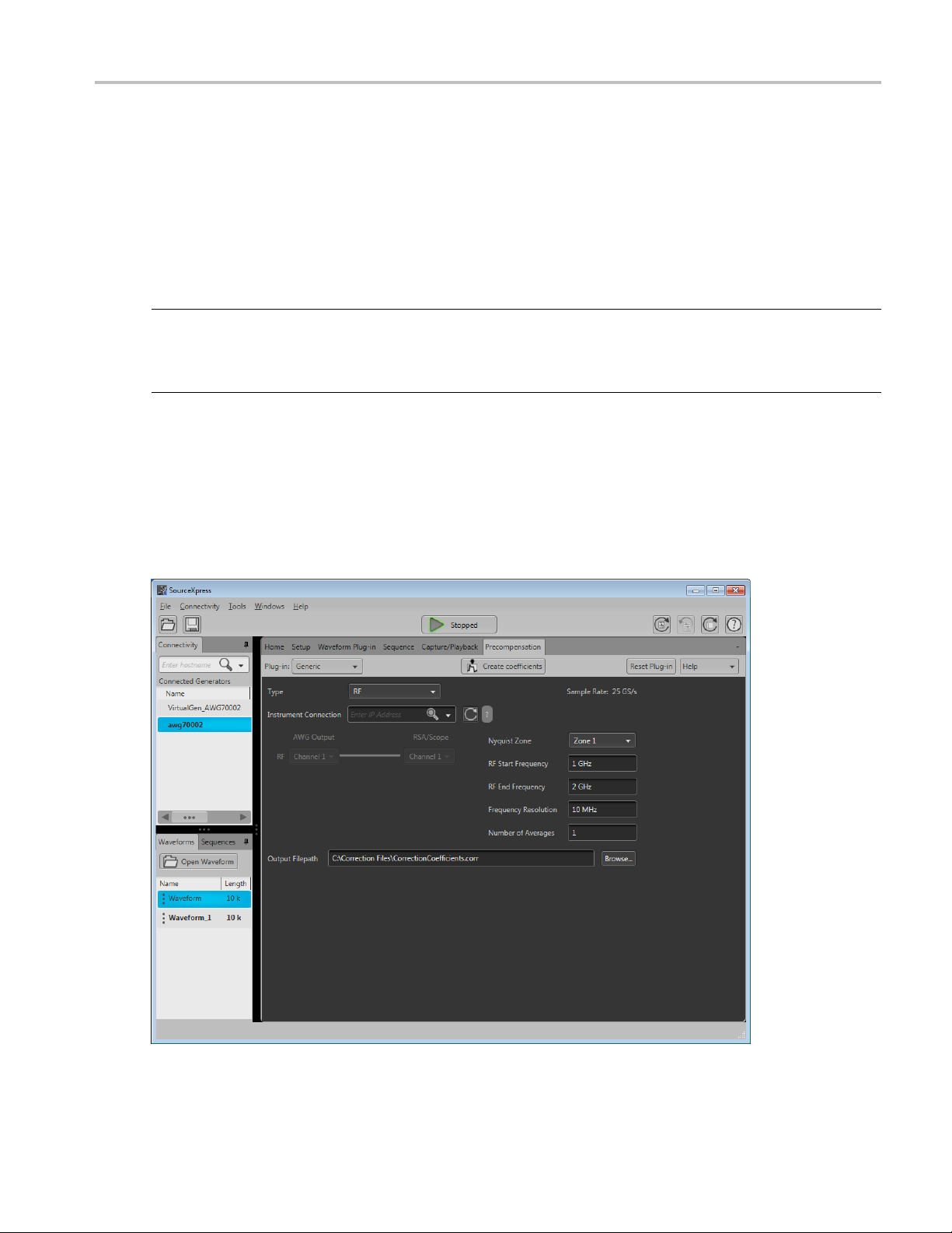
The Generic Precompensation plug-in application is used to create correction coefficients that can be
applied to waveforms to obtain a flat frequency response and linear phase response.
The plug-in is designed to integrate and operate seamlessly as an enhancement to the SourceXpress
waveform creation software application or to an AWG70000A series arbitrary waveform generator.
NOTE. When u
connected to an Arbitrary Waveform Generator (AWG). You cannot use a virtual generator connection to
create coefficient files. Refer to the SourceXpress help for information about establishing a connection
to an AWG.
To create
through the entire system to the point it is connected to an oscilloscope or analyzer. The captured
waveform is then compared to the stimulus signal. From the compared data, the magnitude and the phase
characteristics of the system is obtained and is used to create a correction file.
This illustration shows the Generic Precompensation plug-in viewed from the SourceXpress application.
The plug-in is identical whether it is used from SourceXpress or from an AWG70000A series instrument.
sing the Generic Precompensation Plug-in with SourceXpress, SourceXpress must be
the correction coefficients, a known stimulus signal (golden signal) is generated and passed
Generic Precompensation Printable Help Document 1

Introduction Documentation
Documentation
In addition to this application Help system, the following documentation is available for the software.
All documentation is available on the Tektronix Web site (www.Tektronix.com/manuals
To read about Use these documents
SourceXpre
Connected instrument operation and user
interfac
xxx
Suppor
Tektro
).
ss operation and user interface help
ehelp
Access the S
information on all controls and elements on screen.
The SourceXpress help system is also available in PDF format, available
on the Tekt
For operation and interface help of a connected instrument, refer to the
instrume
This is available with the instrument or on the Tektronix web site
ourceXpress application help from the Help menu for
ronix web site.
nt’s documentation.
t information
nix offers the following services in support of their products:
Technical Support. For application-related questions about a Tektronix product, contact us by
hone or email
telep
Service Support. For service-related questions about a Tektronix product, contact us by telephone
ail
or em
).
).
Tektronix also offers extended warranty and calibration programs as options on many products. Contact
r local Tektronix distributor or sales office.
you
2 Generic Precompensation Printable Help Document

Introduction Feedback
Feedback
Tektronix values your feedback on our products. To help us serve you better, please send any suggestions,
ideas, or other comments you may have regarding your instrument.
Directyourfeedbacktousbyemailatwww.tek.com/home/mytek/survey .
Please be as specificaspossible.
Recommended information to include
Instrument hardware, such as display and chassis type
Application software version
Optional information
Your name, company, mailing address, phone number, and FAX number
Generic Precompensation Printable Help Document 3

Introduction Feedback
4 Generic Precompensation Printable Help Document
Orientation Elements of the display
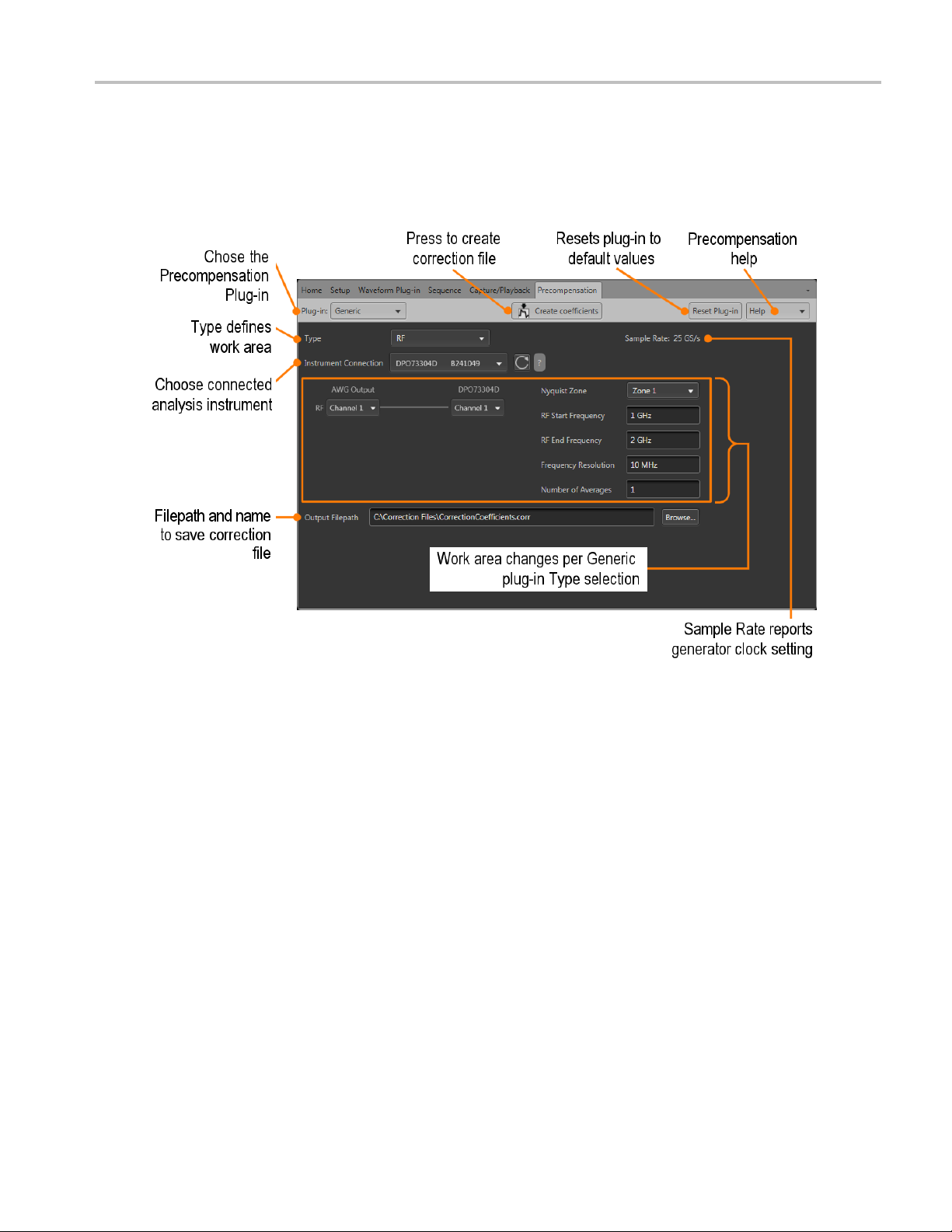
Elements of the display
The main areas of the plug-in window are shown in the following figure.
Plug-
Generic Precompensation Printable Help Document 5
in selection button
utton selects specific types of correction coefficients. At this time, only Generic type coefficients
This b
(RF, IF, and IQ) are available.
re enhancements to Precompensation will provide additional plug-in selections.
Futu

Orientation Create coefficients button
Create coefficients button
Select to create the coefficient file as defined.
The following conditions must be met to create a coefficient file:
The Generic Precompensation plug-in must be licensed for use with the application you are creating
the coefficient file (i.e. SourceXpress or an AWG70000A series generator).
For example, if you connect SourceXpress (without the plug-in license) to an AWG70000A series
generator that is licensed to use the plug-in, you cannot use SourceXpress to create the coefficients.
Refer to the documentation for SourceXpress or the AWG70000A series generators for details about
obtaining and using license files.
Coefficient files cannot be created without the proper instrument connections.
If using the Precompensation Plug-in with SourceXpress, SourceXpress must be connected to an
Arbitrary Waveform Generator (AWG). You cannot use a virtual generator to create coefficient files.
Refer to the SourceXpress help for information a bout establishing a connection to an AWG.
Upon completion of the coefficient file, a response plot is displayed in the Frequency Response display.
Close the window to complete the operation.
NOTE. If using a Real-time Signal Analyzer (RSA) as the analysis instrument, only Magnitude coefficients
are obtained.
NOTE. If using the Generic Precompensation plug-in from an AWG70000A series instrument, coefficients
can not be created if Synchronization (Sync Hub) is enabled. Refer to the instruments help system
for information
6 Generic Precompensation Printable Help Document

Orientation Reset Plug-in button
Reset Plug-in button
Returns the plug-in to the RF type and returns all settings to their default values.
Selecting Reset does not affect the Instrument Connection.
Help button
Help button: Provides links where you can obtain a dditional product help and documentation.
Item Descripti
User manual
About ...
xxx
Opens the p
Provides
helpful when contacting Tektronix about your application.
on
lug-in help system.
you with information about your plug-in application. This information is
Generic Precompensation Printable Help Document 7

Orientation Help button
8 Generic Precompensation Printable Help Document

Instrument Connection Instrument connection
Instrument connection
The Instrument Connection is a common element regardless of the Type selection.
In order to create a coefficient file (correction fi le), a connection to a Tektronix Real-time Signal Analyzer
(RSA) or a Tektronix oscilloscope (Scope) is required. The RSA or Scope replaces the device under
test (DUT) which is at the end-point of the signal.
NOTE. When u
corrected. To create coefficients for both magnitude and phase, you must use an oscilloscope.
If you hav
button
You can connect directly to a networked instrument by entering the IP address of the instrument (e.g.
192.168.1.101).
sing a Real-time Signal Analyzer (RSA) to create coefficients, only the magnitude is
e established a connection to an instrument (or instruments) using TekVISA, use the Refresh
to display and choose the connected instrument.
Generic Precompensation Printable Help Document 9

Instrument Connection Instrument connection
10 Generic Precompensation Printable Help Document

Generic Precompensation Plug-in types Generic Precompensation Plug-in types
Generic Precompensation Plug-in types
The Generic plug-in p rovides the capability to create the following Types of coefficient files:
RF (see page 11)
IF (see page 12)
IQ with modulator (see page 13)
Direct IQ (s
Use the Type pull down menu to select the type signal y ou want to create the correction file (coefficients)
based on yo
As you choose the different Types, the available settings change along with an illustration of the
connecti
being used to capture the resulting signal.
ur setup.
ons that must be made between the arbitrary waveform generator output and the instrument
RF coefficients
The RF coefficients are for a single RF signal from the AWG to the device under test (DUT).
In the example shown, the RF signal is being output from channel 1 of the AWG and input to channel
1 of the connected oscilloscope (DPO73304D).
Use the connection diagram pull-down lists to select the proper output and input channels of your setup.
For RF type coefficients, you can connect to either an oscilloscope or a real time signal analyzer (RSA) to
capture the waveform.
ee page
14)
The settings for the RF type include:
Generic Precompensation Printable Help Document 11

Generic Precompensation Plug-in types IF coefficients
Item Description
Sample Rate: The Sample Rate displays the current AWG’s clock rate. It is not adjustable from the
Precompensat
Nyquist Zone
RF Start Frequency Used in conjunction with the RF End Frequency setting, select the frequency range you want
RF End Frequency
Frequency
Resolution
r of Averages
Numbe
xxx
Choose Nyquis
to create
Start and Stop Frequency settings are based on ½ the available Sample Rate of the AWG and
the Nyquist Zone selection.
Used in conjunction with the RF Start Frequency setting, select the frequency range you want
to creat
Start and Stop Frequency settings are based on ½ the available Sample Rate of the AWG and
the Nyquist Zone selection.
Enter the frequency resolution of the signal to determine the number of frequency points between
start a
the number of times the software sends and captures the signal through the user defined
Enter
configuration to create an average.
Increasing the number of averages reduces the noise level but increases processing time.
ion plug-in.
t Zone 1 or Zone 2.
acorrectionfile.
e a correction file.
nd end frequencies that coefficients will be created.
IF coefficients
The IF coefficients are for a single IF signal from the AWG to the device under test (DUT).
In the example shown, the IF signal is being output from c hannel 1 of the AWG, mixed with the local
oscillator, and input to channel 1 of the connected oscilloscope (DPO73304D).
Use the connection diagram pull-down lists to select the proper output and input channels of your setup.
For IF type coefficients, you can connect to either an oscilloscope or a real time signal analyzer (RSA) to
capture the waveform.
12 Generic Precompensation Printable Help Document

Generic Precompensation Plug-in types IQ with modulator coefficients
The settings for the IF type include:
Item Description
Sample Rate: The Sample Rate displays the current AWG’s clock rate. It is not adjustable from the
Precompensation plug-in.
Sideband Select the frequency band (Upper or Lower) which is to be calibrated.
IF Start Frequency Used in conjunction with the IF End Frequency setting, select the frequency range you want
to create a correction file.
IF End Frequency
Frequency
Resolution
LO Frequency Enter the frequency of the local oscillator to be mixed with the IF signal
Number of Averages Enter the number of times the software sends and captures the signal through the user defined
xxx
Used in conjunction with the IF Start Frequency setting, select the frequency range you want
to create a correction file.
Enter the frequency resolution of the signal to determine the number of frequency points between
start and end frequencies that coefficients will be created.
configuration to create an average.
Increasing the number of averages reduces the noise level but increases processing time.
IQ with modulator coefficients
The IQ with modulator coefficients are individual I and Q signals from the AWG and modulated with a
carrier frequency to provide a single RF signal to the device under test (DUT).
In the example shown, the I and Q signals are being output from channels 1 and 2 of the AWG, modulated
with a 30 GHz carrier frequency, and input to channel 1 of the connected oscilloscope (DPO73304D).
Use the connection diagram pull-down lists to select the proper output and input channels of your setup.
For IQ with modulator type coefficients, you can connect to either an oscilloscope or a real time signal
analyzer (RSA) to capture the waveform.
Generic Precompensation Printable Help Document 13

Generic Precompensation Plug-in types Direct IQ coefficients
The settin
Item Description
Sample Rate: The Sample Rate displays the current AWG’s clock rate. It is not adjustable from the
Baseban
Frequen
Resolution
Carrier Frequency Enter the carrier frequency of the modulator to create the RF signal.
Number of Averages Enter the number of times the software sends and captures the signal through the user defined
xxx
gs for the IQ with modulator type include:
Precompe
dOffset
cy
The defa
signal center + or – from the carrier frequency.
Enter the frequency resolution of the signal to determine the number of frequency points between
start and end frequencies that coefficients will be created.
config
Increasing the number of averages reduces the noise level but increases processing time.
Direct IQ coefficients
The Direct IQ coefficients are individual I and Q signals from the AWG and connected directly to the
device under test (DUT).
In the example shown, the I and Q signals are being output from channels 1 and 2 of the AWG and input
to channels 1 and 3 of the connected oscilloscope (DPO73304D).
nsation plug-in.
ult signal is centered at the Carrier Frequency. The Baseband Offset changes moves the
uration to create an average.
Use the connection diagram pull-down lists to select the proper output and input channels of your setup.
or Direct IQ coefficients, you must connect to an oscilloscope to capture the waveform since two
F
channels are required.
14 Generic Precompensation Printable Help Document

Generic Precompensation Plug-in types Direct IQ coefficients
The settings for the Direct IQ type include:
Item Description
Sample Rate: The Sample Rate displays the current AWG’s clock rate. It is not adjustable from the
Precompensation plug-in.
Bandwidth
Baseband Offset The default signal is centered at the Bandwidth Frequency. The Baseband Offset changes moves
Frequency
Resolution
r of Averages
Numbe
xxx
Enter the bandwidth of the signal.
The avai
lable bandwidth setting is dependent on the AWG’s sample rate and the Frequency
Resolution setting.
the signal center + or – from the bandwidth frequency.
Enter the frequency resolution of the signal to select the number of samples between start and
quencies.
end fre
the number of times the software sends and captures the signal through the user defined
Enter
configuration to create an average.
Increasing the number of averages reduces the noise level but increases processing time.
Generic Precompensation Printable Help Document 15

Generic Precompensation Plug-in types Direct IQ coefficients
16 Generic Precompensation Printable Help Document

Output Filepath Output Filepath
Output Filepath
The Output Filepath is a common element to all Generic plug-in Types. .
You can enter a directory path and file name directly in the fi eld or use the Browse... button to display the
Save As screen a nd navigate to a location to name and save the file.
Generic Precompensation Printable Help Document 17

Output Filepath Output Filepath
18 Generic Precompensation Printable Help Document

Apply the Coefficient file Apply the Coefficient file
Apply the Coefficient file
T o use a coefficient file, you need to apply the correction file to a waveform. You can use either the
SourceXpress applic ation or an AWG70000A series instrument to perform the operation if the Generic
Precompensa
Use the Waveforms list to select the waveform(s) and then select Apply Corrections.
RF coefficients can be applied to Real, I, or Q files. Select a single waveform and apply the correction
file.
IQ coefficients must be applied to two waveforms, I and Q. Select the two waveforms (high lighting
both at the same time) and apply the correction file.
tion plug-in is installed.
A window opens to allow you to navigate to the saved coefficient file (correction file). When applying
corrections, the application displays a Frequency Response window showing the plot information and
actions to take.
Generic Precompensation Printable Help Document 19

Apply the Coefficient file Apply the Coefficient file
Choose to either create a new waveform or overwrite the existing waveform. (For RF type corrections, you
also have the Advanced options to apply a Gaussian filter or remove Sin(x)/x distortions.
Select Apply to complete the operation.
Refer to the application help (for either SourceXpress or the AWG70000A series instruments) for
information about using the Waveforms list.
20 Generic Precompensation Printable Help Document

Coefficient file structure Coefficient file structure
Coefficient file structure
The coefficient file created is an ascii (human readable) file with .corr as the file extension. This section
describes the structure and contents of a typical correction file.
Coefficient files are created using the Touchstone file format.
Referencing the example coefficient file provided, here are some key e lements:
Line Description
1—14
15
16
17 — ...
xxx
Comments lines providing basic setup information, including the instruments that were used.
This line includes the # symbol, indicating the start of the coefficient data. The # symbol is required.
The characters following the # symbol are not required. In this example, they indicate the following:
Hz: The data is in Hertz.
S: S-Parameter file format
DB: Data is in magnitude (dB)
R 50: The coefficients are in reference to a 50 Ω system setup
A comment line indicating the contents of the data columns.
In the example, the columns are:
Frequency, Magnitude (dB (S21), and Phase (deg (s21)
Contains the coefficient data.
Generic Precompensation Printable Help Document 21

Coefficient file structure Coefficient file structure
22 Generic Precompensation Printable Help Document

Licensing Licensing
Licensing
A license is required for this plug-in to become operational. The plug-in must be licensed for use with the
host application from where you want to use the plug-in.
For example, to use the plug-in from SourceXpress, SourceXpress must have a license. To use the plug-in
from an instrument, the instrument must have a license.
Refer to the application help (for either SourceXpress or the AWG70000A series instruments) for complete
information about obtaining and installing license files.
Generic Precompensation Printable Help Document 23

Licensing Licensing
24 Generic Precompensation Printable Help Document

Error messages Error codes
Error codes
The following table lists error codes and messages that are unique to the Generic Precompensation plug-in.
Error code Error message
7812
7813
7814
7815
7816
7817
7818
7819
7820
7821
7822 Precompensation Error. Unable to trigger, signal amplitude too low.
7823 Precompensation Error. Unable to capture signal, signal is clipping.
7824 Precompensation Error. U nable to c apture s ignal. Amplitude is too large.
7825
7826
7830 Precompensation Error. Resolution too large. Need a better resolution.
7831
7832 Precompensation Error. Unable to create stimulus. Requires more than two tones. Need a larger
7833
7834
7835 Precompensation Error. Bandwidth cannot be less than or equal to 0.
7836
7837
7838
7839
7840
7841
7842
7843
Instrument Connection Error. Failed to connect to the selected instrument.
Instrument Connection Error. Please connect to an instrument to continue.
Precompensation Error. Error during calculation of coefficients.
Precompensation Error. Error while setting Oscilloscope Record Length.
Check instrument connections and retry.
Precompensation Error. Access to correction file denied.
Precompensation Error. Invalid Output Filepath for correction file.
Precompensation Error. Correction file not found.
Precompensation Error. Cannot calculate coefficients using a virtual generator.
Precompensation Setup Error. Cannot use an RSA with a Direct IQ setup.
Precompensation Error. No good signal correlation between the captured and reference signals.
Sample Rate Error. Insufficient sample rate. Please increase to <recommended value> or higher.
Recommended value is dependent on current setup.
Precompensation Error. Captured waveform length is insufficient for calculation of coefficients.
Precompensation Error. Too few trace points.
span or smaller resolution.
Precompensation Error. Desired start frequency is lower than the set resolution.
Precompensation Error. 80% of the data captured is below noise floor.
Precompensation Error. Creation of coefficients already in progress.
Precompensation Setup Error. Cannot use an ATI Channel and Non-ATI channel with a Direct
IQ setup.
Precompensation Setup Error. Cannot use the same AWG Channel for I and Q with an IQ setup.
Precompensation Setup Error. Cannot use the same Scope Channel for I and Q with an IQ setup.
Precompensation Setup Error. Input parameters are greater than instrument parameters. Please
reduce Bandwidth/Start/End Frequencies.
Precompensation Setup Error. Input parameters is setting analysis frequency to less than or
equal to zero.
Precompensation Setup Error. Sample Rate cannot be less than or equal to 0 or NaN.
Precompensation Error. AWG play timed out. Please check settings and try again.
Generic Precompensation Printable Help Document 25

Error messages Error codes
Error code Error message
7844
7850
7851
7852
7853
7854
7856
7857
7858
7859
7860
7861
7862
xxx
Precompensation Error. Cannot create correction coefficients with Sync Hub enabled.
Asset not found. Unable to access selected asset.
Correction file not supported. Only dB-Angle correction files are supported.
Refer to Coef
Correction
ficient file structure
file not supported. Only Scattering correction files are supported.
Refer to Coefficient file structure
(see page 21).
(see page 21).
Error Calculating Correction Parameter. Unable to calculate <parameter> from correction file.
Frequency Count Mismatch. When reading the correction file, the number of frequencies <current
value> did not match the expected number <expected value>.
The curre
Precompe
Error us
nt value is based on the correction file.
nsation Apply Error. E rror while applying correction coefficients.
ing Waveform Sample Rate. Sampling Rate must be set for <waveform name> waveform
to apply correction coefficients.
Precompensation Apply Error. Cannot apply IQ Correction Coefficients to a Real Signal.
Precompensation Apply Error. Cannot apply < signal format> Correction Coefficient to a <signal
format value> Signal Format waveform.
to Apply the Coefficient file
Refer
mpensation Apply Error. C orrections are c urrently being applied.
Preco
ompensation Apply Error. No sample rate detected in file.
Prec
ompensation Apply Error. Too few frequency points detected in file.
Prec
(see page 19).
26 Generic Precompensation Printable Help Document

Index
Index
A
Apply corrections, 19
B
Bandwidth,
Baseband Offset, 15
15
C
Carrier Frequency, 14
Coefficient file
apply, 19
Direct IQ, 14
IF, 12
IQ with modulator, 13
RF, 11
structure, 21
Coefficient file structure, 21
Corrections file
,19
apply
Create coefficients, 6
D
Direct IQ coefficients, 14
bandwidth, 15
baseband offset, 15
frequency resolution, 15
splay elements, 5
Di
Documentation, 2
Connected instrument, 2
SourceXpress, 2
E
Elements of the display, 5
F
Feedback, 3
Frequency Re
solution, 14
G
Generic Plug-in types, 11
Generic Precompensation plug-in
description, 1
H
Help menu, 7
I
IF coefficients, 12
ncy resolution, 13
freque
IF end frequency, 13
IF start frequency, 13
LO frequency, 13
sideband, 13
IF End Frequency, 13
art Frequency, 13
IF St
Instrument connection, 9
IQ with modulator coefficients, 13
baseband offset, 14
carrier frequency, 14
frequency resolution, 14
L
icense, 6
L
Licensing, 23
LO Frequency, 13
Local oscillator, 13
N
Nyquist Zone, 12
O
Output File
path, 17
P
Plug-in licensing, 23
Plug-in selection, 5
Plug-in types, 11
R
Reset Plug-in, 7
RF coefficients, 11
ncy resolution, 11
freque
Nyquist zone, 11
RF end frequency, 11
RF start frequency, 11
RF End Frequency, 12
RF Start Frequency, 12
S
vice support, 2
Ser
Sideband, 13
Support information, 2
T
Technical support, 2
Generic Precompensation Printable Help Document 27
 Loading...