


xx
FCA3000, FCA3100, & MCA3000 Series
ZZZ
Timer/Counter/Analyzers
Specifications and Performance Verification
*P077049504*
077-0495-04


xx
FCA3000, FCA3100, & MCA3000 Series
ZZZ
Timer/Counter/Analyzers
Specifications and Performance Verification
Revision A
www.tek.com
077-0495-04

Copyright © Tektronix. All rights reserved. Licensed software products are owned by Tektronix or its subsidiaries
or suppliers, and are protected by national copyright laws and international treaty provisions.
Tektronix products are covered by U.S. and foreign patents, issued and pending. Information in this publication
supersedes that in all previously published material. Specifications and price change privileges reserved.
TEKTRONIX and TEK are registered trademarks of Tektronix, Inc.
Contacting Tektronix
Tektronix, Inc.
14150 SW Karl Braun Drive
P.O. Box 500
Beaverto
USA
For product information, sales, service, and technical support:
n, OR 97077
In North America, call 1-800-833-9200.
Worldwide, visit www.tek.com to find contacts in your area.

Warranty
Tektronix warrants that this product will be free from defects in materials and workmanship for a period of one (1)
year from the date of shipment. If any such product proves defective during this warranty period, Tektronix, at its
option, either will repair the defective product without charge for parts and labor, or will provide a replacement
in exchange for the defective product. Parts, modules and replacement products used by Tektronix for warranty
work may be n
the property of Tektronix.
ew or reconditioned to like new performance. All replaced parts, modules and products become
In order to o
the warranty period and make suitable arrangements for the performance of service. Customer shall be responsible
for packaging and shipping the defective product to the service center designated by Tektronix, with shipping
charges prepaid. Tektronix shall pay for the return of the product to Customer if the shipment is to a location within
the country in which the Tektronix service center is located. Customer shall be responsible for paying all shipping
charges, duties, taxes, and any other charges for products returned to any other locations.
This warranty shall not apply to any defect, failure or damage caused by improper use or improper or inadequate
maintenance and care. Tektronix shall not be obligated to furnish service under this warranty a) to repair damage
result
b) to repair damage resulting from improper use or connection to incompatible equipment; c) to repair any damage
or malfunction caused by the use of non-Tektronix supplies; or d) to service a product that has been modified or
integrated with other products when the effect of such modification or integration increases the time or difficulty
of servicing the product.
THIS WARRANTY IS GIVEN BY TEKTRONIX WITH RESPECT TO THE PRODUCT IN LIEU OF ANY
OTHER WARRANTIES, EXPRESS OR IMPLIED. TEKTRONIX AND ITS VENDORS DISCLAIM ANY
IMPLIED WARRANTIES OF MERCHANTABILITY OR FITNESS FOR A PARTICULAR PURPOSE.
TRONIX' RESPONSIBILITY TO REPAIR OR REPLACE DEFECTIVE PRODUCTS IS THE SOLE
TEK
AND EXCLUSIVE REMEDY PROVIDED TO THE CUSTOMER FOR BREACH OF THIS WARRANTY.
TEKTRONIX AND ITS VENDORS WILL NOT BE LIABLE FOR ANY INDIRECT, SPECIAL, INCIDENTAL,
OR CONSEQUENTIAL DAMAGES IRRESPECTIVE OF WHETHER TEKTRONIX OR THE VENDOR HAS
ADVANCE NOTICE OF THE POSSIBILITY OF SUCH DAMAGES.
[W2 – 15AUG04]
btain service under this warranty, Customer must notify Tektronix of the defect before the expiration of
ing from attempts by personnel other than Tektronix representatives to install, repair or service the product;


Table of Contents
Important safety information........... .................................. ................................ ........ iv
General safety summary ..................................................................................... iv
Service safety summary............................ ................................ .......................... vi
Terms in t hi
Symbols and terms on the product ......................................................................... vii
Specifications .. .................................. ................................ ................................ ... 1
Performance Verification ................... .................................. ................................ .... 17
Test Record............ ................................ .................................. ...................... 19
Internals Calibration .......................................................................................... 23
Channel
Front End Characteristics .................................................................................... 25
Sensitivity, DC–400 MHz at 1X Attenuation.... . .... . ..... . ..... . .... . . .... . ..... . ..... . .... . ..... . ..... . 30
Timebase Accuracy........................................................................................... 33
Quantization Error ............................................................................................ 34
External Reference Clock Frequency and Sensitivity . . .... . ..... . ..... . ..... ..... . ..... . ..... . .... . ..... 37
10 MH
Channel C (if installed) Input Impedance.................................................................. 39
Channel C (if installed) Frequency Sensitivity .... . ..... . ..... . .... . ..... . ..... . ..... . .... . . .... . ..... . ... 41
s manual ..... ................................ .................................. .................. vi
A and B Input Resistance................................ ................................ .......... 24
z Out Amplitude .... . ..... . ..... . ..... . ..... ..... . ..... . ..... . ..... . ..... . ... . . . .... . ..... . ..... . ..... 39
FCA3000, FCA3100, and MCA3000 Series Specifications and Performance Verification i

Table of Contents
List of Figure
Figure 1: Numerical Analysis display........................................................................... 28
s
ii FCA3000, FCA3100, and MCA3000 Series Specifications and Performance Verification

List of Tables
Table 1: Input characteristics, channels A and B ............................................................... 1
Table 2: Inp
Table 3: Input characteristics, channel C (frequency and period only) . . ..... . ..... . .... . . .... . ..... . ..... . .. 3
Table 4: Timebase error characteristics ....................... ................................ ................... 4
Table 5: Guaranteed measurement capabilities ................................................................. 5
Table 6: Other available readings.......... ................................ .................................. .... 13
Table 7: Other option capabilities . . ..... . ..... . ..... . ..... . ..... . .... . ..... . ..... . ..... . ..... . ... . . . .... . ..... . . 14
Table 8 : S
Table 9: Power ..................................................................................................... 15
Table 10: I/O connectors.......................................................................................... 15
Table 11: Display characteristics ................................................................................ 16
Table 12: Mechanical Characteristics ..... .................................. ................................ .... 16
Table 13: Environmental performance – Laboratory Products............... ................................ 16
Table
Table 15: Test record ............................ .................................. ................................ 19
Table 16: Front End Characteristics Worksheet........................................ ........................ 22
ut characteristics, Rear Panel I/O.... .................................. ............................. 2
oftware functions ...................... ................................ ................................ 14
14: Recommended Equipment............................................................................ 17
Table of Contents
FCA3000, FCA3100, and MCA3000 Series Specifications and Performance Verification iii

Important safety information
Important saf
ety information
This manual c
for safe operation and to keep the product in a safe condition.
To safely perform service on this product, additional information is provided at
the end of this section. (See page vi, Servicesafetysummary.)
General safety summary
Use the product only as specified. Review the following safety precautions to
avoid injury and prevent damage to this product or any products connected to it.
Carefully read all instructions. Retain these instructions for future reference.
Comply with local and national safety codes.
For correct and safe operation of the product, it is essential that you follow
generally accepted safety procedures in addition to the safety precautions specified
in this manual.
The product is designed to be used by trained personnel only.
Only qualified personnel who are aware of the hazards involved should remove
the cover for repair, maintenance, or adjustment.
ontains information and warnings that must be followed by the user
To avoid fire or personal
injury
Before use, always check the product with a known source to be sure it is
operating correctly.
This product is not intended for detection of hazardous voltages.
Use personal protective equipment to prevent shock and arc blast injury where
hazardous live conductors are exposed.
While using this product, you may need to access other parts of a larger system.
Read the safety sections of the other component manuals for warnings and
cautions related to operating the system.
When incorporating this equipment into a system, the safety of that system is the
responsibility of the assembler of the system.
Use proper power cord. Use only the power cord s pecified for this product and
certified for the country of use.
Do not use the provided power cord for other products.
Ground the product. This product is grounded through the grounding conductor
of the power cord. To avoid electric shock, the grounding conductor must be
connected to earth ground. Before making connections to the input or output
terminals of the product, make sure that the product is properly grounded.
iv FCA3000, FCA3100, and MCA3000 Series Specifications and Performance Verification

Important safety information
Do not d isable t
Power disconnect. The power cord disconnects the product from the power
source. See instructions for the location. Do not position the equipment so that it
is difficult to access the power cord; it must remain accessible to the user at all
times to allow for quick disconnection if needed.
Connect and disconn
leads while they are connected to a voltage source.
Observe all terminal ratings. To a void fire or shock hazard, observe all ratings
and markings on the product. Consult the product manual for further ratings
information before making connections to the product.
Do not apply a potential to any terminal, including the common terminal, that
exceeds the maximum rating of that terminal.
The measuring terminals on this product are not rated for connection to mains or
Category II, III, or IV circuits.
Do not operate without covers. Do not operate this product with covers or panels
removed, or with the case open. Hazardous voltage exposure is possible.
Avoid exposed circuitry. Do not touch exposed connections and components
when power is present.
he power cord grounding connection.
ect properly. Do not connect or disconnect probes or test
Do not operate with suspected failures. If you suspect that there is damage to this
product, have it inspected by qualified service personnel.
Disable the product if it is damaged. Do not use the product if it is damaged
or operates incorrectly. If in doubt about safety of the product, turn it off and
disconnect the power cord. Clearly mark the product to prevent its further
operation.
Use only specified replacement parts.
Use proper fuse. Use only the fuse type and rating specified for this product.
Do not operate in wet/damp conditions. Be aware that condensation may occur if
a unit is moved from a cold to a warm environment.
Do not operate in an explosive atmosphere.
Keep product surfaces clean and dry. Remove the input signals before you clean
the p roduct.
Provide proper ventilation. Refer to the installation instructions in the manual for
details on installing the product so it has proper ventilation.
Slots and openings are provided for ventilation and should never be c overed or
otherwise obstructed. Do not push objects into any of the openings.
FCA3000, FCA3100, and MCA3000 Series Specifications and Performance Verification v

Important safety information
Provideasafew
convenient for viewing the display and indicators.
Be sure your wo
ergonomics professional to avoid stress injuries.
Servicesafetysummary
The Service safety summary section contains additional information required to
safely perform service on the product. Only qualified personnel should perform
service procedures. Read this Service safety summary and the General safety
summary before performing any service procedures.
To avoid e
Do not service alone. Do not perform internal service or adjustments of this
product unless another person capable of rendering first aid and resuscitation is
present.
Discon
disconnect the power cord from the mains power before removing any covers or
panels, or opening the case for servicing.
orking environment. Always place the product in a location
rk area meets applicable ergonomic standards. Consult with an
lectric s hock. Do not touch exposed connections.
nect power. To avoid electric shock, switch off the product power and
Termsinthismanual
Use care when servicing with power on. Dangerous voltages or currents may exist
in this product. Disconnect power, remove battery (if applicable), and disconnect
t leads before removing protective panels, soldering, or replacing components.
tes
Verify safety after repair. Always recheck ground continuity and mains dielectric
strength after performing a repair.
These terms may appear in this manual:
WARNING. Warning statements identify conditions or practices that could result
in injury or loss of life.
CAUTION. Caution statements identify conditions or practices that could result in
damage to this product or other property.
vi FCA3000, FCA3100, and MCA3000 Series Specifications and Performance Verification

Important safety information
Symbols and te
rms on the product
These terms may appear on the product:
DANGER indicates an injury hazard immediately accessible as you read
the marking.
WARNING indicates a n injury hazard not immediately accessible as you
read the marking.
CAUTION indicates a hazard to property including the product.
When this symbol is marked on the product, be sure to consult the manual
to find out the nature of the potential hazards and any actions which have to
be taken to avoid them. (This symbol may also be used to refer the user to
ratings in the manual.)
The follo
wing symbol(s) may appear on the product:
FCA3000, FCA3100, and MCA3000 Series Specifications and Performance Verification vii

Important safety information
viii FCA3000, FCA3100, and MCA3000 Series Specifications and Performance Verification

Specifications
This chapter contains the specifications for the instrument. Specifications that are
marked with the symbol are checked in the manual. All specifications apply
to all models
Table 1: Input characteristics, channels A and B
unless noted otherwise.
Characteristic
Description
Frequency Range, DC Coupled DC to 300 MHz
Verified as part of Sensitivity, DC to 300 MHz, 1X Attenuation
Frequency Range, AC Coupled 10 Hz to 300 MHz, 1 MΩ input impedance
10 Hz to 300 MHz, 50 Ω input impedance
10 Hz to 400 MHz Manual Trigger Mode, DC Coupled, 50 Ω
Verified as part of Sensitivity - DC–300 MHz, 1X Attenuation
Impedance, Front Panel, 1 MΩ 1MΩ, DC, 1X/10X mode: 1.0 MΩ (±5%) || 14 pF (±2 pF)
1MΩ, AC, 1X mode: 1.3 MΩ (±5%) || 14 pF (±2 pF)
1MΩ, AC, 10X mode: 1.0 MΩ (±5%) || 14 pF (±2 pF)
Impedance, Front Panel, 50 Ω
Impedance, Rear Panel inputs
(Option RP)
50 Ω Input Protection
Trigger Slope
Maximum Channel Timing
50Ω, AC/DC, 1X/10X mode: 50 Ω (±5%); VSWR ≤2:1
1MΩ || 50 pF
50 Ω (VSWR ≤2:1)
None
Positive or negative
500 ps
Difference
Amplifier Noise Level (1X)
Amplifier Noise Level (10X)
Hysteresis Window, 1X
500 μV
200 μV
5mV
2mV
<(30 mV +|1% of trigger level|) for Pulse Width and Duty Factor measurements
(guaranteed)
RMS
(typical)
RMS
(guaranteed)
RMS
(typical)
RMS
Hysteresis window compensation exists to: 6 mV ±1% of trigger level over a frequency range
of DC to 10 kHz for other measurement functions
Hysteresis Window, 10X
<(300 mV ±|1% of trigger level|) for Pulse Width and Duty Factor measurements
Hysteresis window compensat ion exists to: 60 mV ±1% of trigger level over a frequency range
of DC to 10 kHz for other measurement functions
Sensitivity, DC to 400 MHz,
1X Attenuation
DC to 200 MHz
200 MHz to 300 MHz 25 mV
15 mV
Auto Trig 35 mV
Attenuation
Dynamic Range, 1X
Trigger Level
Resolution
1X, 10X ratio within 5%
Minimum Sensitivity to 10 V
within ±5 V window
p-p
Trigger level as read out on display has the following characteristics
FCA3000, MCA3000 S eries: 3 mV
FCA3100 Series: 1 mV
RMS
RMS
RMS
FCA3000, FCA3100, and MCA3000 Series Specifications and Performance Verification 1

Specifications
Table 1: Input characteristics, channels A and B (cont.)
Characteristic
Trigger Level Uncertainty,
1X
Trigger Level Uncertainty,
10X
Description
±(15 mV + 1% of trigger level)
TLU for uncertainty analysis purposes
±(150 mV + 1% of trigger level)
Tested as part of Trigger Level Uncertainty (1X)
AUTO Trigger Level Trigger level is automatically set to 50% point of input signal (10% and 90% for Rise/Fall Time)
AUTO Hysteresis, Time Minimum hysteresis window (hysteresis compensation)
AUTO Hysteresis, Frequency One third of input signal level
Instrument measures Signal(high) + Noise(pk) - ½ hysteresis and Signal(low) – Noise(pk) + ½
hysteresis to calculate 30% and 70% levels for auto-hysteresis
Analog LP Filter
Nominal 100 kHz, RC-type
Digital Hold-Off Filter 1 Hz to 50 MHz cut-off frequency
Software fi lter programs FPGA to hold-off
Maximum Voltage Without Damage
1MΩ: 350 V (DC + AC pk) to 440 Hz, falling to 12 V
50 Ω:12V
, 35 V peak for duty factor less than 0.1%
RMS
RMS
at 1 MHz
Connector 50 Ω BNC
Table 2: Input characteristics, Rear Panel I/O
Characteristic
Reference Input
requencies
F
Amplitude
nput Impedance
I
ull-In Range
P
Reference Output Outputs the internal reference signal
Frequency 10 MHz
Amplitude
Arming Input
Frequency Range
Input Impedance
Threshold
Slope Selectable Positive or Negative
Pulse Output (FCA3100 Series) Capable of outputting a variable mode pulse
Modes
Period 20 n s to 2 s in 10 ns increments
Pulse Width 10 ns to 2 s in 10 ns increments
Output Level TTL into 50 Ω (1.4 V nominal, 0.4 VOL,2.4VOH)
Description
1, 5, or 10 MHz
0.1 to 5 V
RMS
sinewave
>1 kΩ
5 ppm
>1 V
RMS
into 50 Ω
Arming of all measurement functions
DC to 80 MHz
1kΩ
TTL (1.4 V nominal, 0.8 V
,2.0VIH)
IL
Pulse Out, Gate Open, Alarm Out
2 FCA3000, FCA3100, and MCA3000 Series Specifications and Performance Verification

Specifications
Table 3: Input c
haracteristics, channel C (frequency and period only)
Characteristic Description
High Frequenc
y Range
Product Min Frequency Max Frequency
FCA3003, FCA
FCA3020, FC
MCA3027
MCA3040
Connector
FCA3003, F
FCA3020, FCA3120
MCA3027, MCA3040 Front Panel: 2.92 mm female with field r eplaceable fusible
Impedance
VSWR
50 Ω nominal
FCA3003, FCA3103, MCA3040: VSWR <2.5:1
FCA3020, FCA3120, MCA3027: VSWR <2.0:1
Prescaler Factor
FCA3003, FCA3103: 16
FCA3020, FCA3120: 128
Sen
sitivity
Measured using a sine wave of stated level rms. Harmonic content -10 dBc or more. All
ts are 50 Ω.
inpu
3003, FCA3103
FCA
100 MHz to 300 MHz
0.3 GHz to 2.5 GHz
GHz to 2.7 GHz
2.5
2.7 GHz to 3.0 GHz
FCA3020, FCA3120
250 MHz to 500 MHz
.5 GHz to 18 GHz
0
18 GHz to 20 GHz
MCA3027, MCA3040
300 MHz to 18 GHz
18 GHz to 20 GHz
20 GHz to 27 GHz
27 GHz to 40 GHz:
Overload Indicator
+10 dBm (0.7 V
(MCA3027, MCA3040
Maximum Voltage Maintaining
+13 dBm (1.0 V
Function (MCA3027, MCA3040)
Maximum Voltage without Damage
FCA3003, FCA3103: +34 dBm (12 V
FCA3020, FCA3120: +27 dBm (5 V
MCA3027, MCA3040: +18 dBm (1.78 V
3103
A3120
CA3103,
RMS
RMS
100 MHz
250 MHz
300 MHz
300 MHz
Front pane
l: Type N female
3GHz
20 GHz
27 GHz
40 GHz
Rear panel: SMA female
link
RMS
RMS
RMS
RMS
RMS
RMS
RMS
RMS
RMS
RMS
RMS
)
)
)
)
)
)
)
)
)
)
)
dBm (20 mV
–21
–27 dBm (10 m V
–21 dBm (20 mV
5 dBm (40 m V
–1
–21 dBm (20 mV
–27 dBm (10 m V
21 dBm (20 mV
–
–33 dBm (5 mV
–29 dBm (8 mV
–27 dBm (10 m V
–23 dBm (16 m V
)
)
)
RMS
)
RMS
)
RMS
FCA3000, FCA3100, and MCA3000 Series Specifications and Performance Verification 3

Specifications
Table 3: Input characteristics, channel C (frequency and period only) (cont.)
Characteristic Description
AM tolerance
FCA3003, FCA3103 DC to 0.1 MHz modulation: up to 94% depth
0.1 MHz to 6 MHz modulation: Signal level with lowest output
must meet sensitivity requirements. Signal level at highest
level must not exceed maximum voltage requirements. Within
these constraints >85% AM is acceptable.
FCA3020, FCA3120 Signal level with lowest output must meet sensitivity
requirements. Signal level at highest level must not exceed
maximum voltage requirements. Within these constraints
>90% AM is acceptable.
MCA3027 MCA3040 Signal level with lowest output must meet sensitivity
requirements. Signal level at highest level must not exceed
maximum voltage requirements.
FM tolerance
(MCA3027, MCA3040)
Manual: 50 MHz
Auto: 20 MHz
p-p
atf>3.5GHz;30MHz
P-P
at f ≤3.5 GHz
P-P
for modulation frequency >100 kHz
Table 4: Timebase error characteristics
Characteristic Description
Tim
ebase Error
Timebase Error (TBE) is the sum of the relevant uncertainties depending upon aging, temperature,
ption.
and o
Standard
me base type
Ti
certainty due to:
Un
TCXO OCXO OCXO OCXO
Aging:
.a.
er 24h
p
per month
per year
n
<5×10
<5×10
-7
-6
Temperature variation:
-5
0°C-50°C
20 °C - 26 °C (typical)
Short term stability: t = 1 s
<1×10
-6
<3×10
not specified
(root Allan Variance) t = 10 s
ion MS
Opt
(Medium S tability)
1
-9
5×10
<
-8
<6×10
-7
<2×10
-8
<5×10
-8
<2×10
-10
<1×10
-10
<1×10
ion
Opt
Opt
(High Stability)
<
<1×10
<5×10
<5×10
<1×10
<1×10
<1×10
ion HS
5×10
-10
-8
-8
-9
-9
-11
-11
ion US
Opt
(Ultra High Stability)
1
<
<3×10
<1.5×10
<2.5×10
<4×10
<5×10
<5×10
3×10
-10
-9
-10
-12
-12
1
-8
-9
4 FCA3000, FCA3100, and MCA3000 Series Specifications and Performance Verification

Table 4: Timebase error characteristics (cont.)
Characteristic Description
Power-on stability
Deviation versus final value
after 24h on time,
after a warm-up time of:
n.a.
30 min
Total uncertainty, for operating
temperature
20 °C to 26 °C, at 2σ (95%)
confidence interval:
1 year after calibration
2 years after calibration
1
After 1 month of continuous operation.
<7×10
<1.2×10
-6
-5
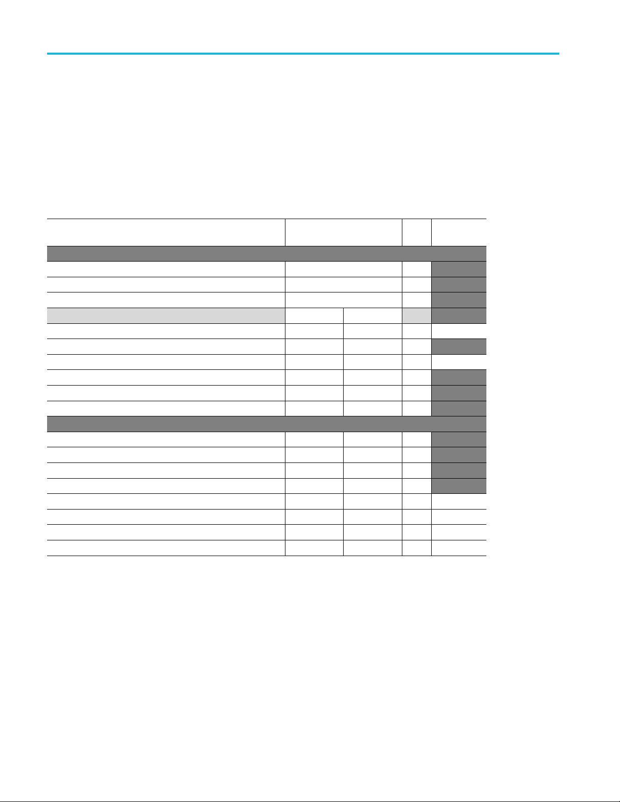
Table 5: Guaranteed measurement capabilities
Characteristics Description
Measurement Control
Measuring Time
Quantization Error
Trigger Error
20 ns to 1000 s for Frequency, Burst, and Period Average
Single cycle for other measuring functions.
FCA3000 Series
FCA3100 Series
MCA3000 Series
<1×10
30 min
<2.4×10
<4.6×10
Specifications
-7
-7
-7
100 ps
65 ps
100 ps
<1×10
10 min
<0.6×10
<1.2×10
RMS
RMS
RMS
-8
<5×10
-9
10 min
-7
-7
<1.8×10
<3.5×10
-8
-8
Where:
ANL = Input N
oise Level (Amplifier Noise Level) (3.1.6)
CNL = Customer Input Signal Noise Level
SSR = S ignal Slew Rate at trigger level
er S ignal Single Period Jitter
RMS
Gate Time U
Mixer Jitter
(MCA3000 c
Timebase
Reference
ncertainty
hannel C only)
SPJ =Custom
200 ps
50 ps
RMS
Internal, External, or Automatic
Display Hold Freezes result, until a new measurement is initiated via Restart.
FCA3000, FCA3100, and MCA3000 Series Specifications and Performance Verification 5

Specifications
Table 5: Guaranteed measurement capabilities (cont.)
Characteristics Description
Limit Alarm Settings
Frequency
Resolution
Low Frequency Capability Ch A and B : 0.002 Hz
Total Measurement
Uncertainty
(FCA3000, FCA3100,
MCA3000 Series channels A
and B)
Total Measurement
Uncertainty
(MCA3000 Series c hannel C)
Graphical indication on front panel and/or SRQ using GPIB, plus pulse on output connector
(FCA3100 Series)
Limit Values: Lower limit, Upper limit
Settings: OFF or Alarm if value is above/below/inside or outside limits
On Alarm: STOP or CONTINUE
Display: Numeric and Graphic
Capable of measuring frequency on any of up to three inputs.
12 digits in 1 s measuring time (normal)
Ch C: Specification covered in Channel C table
Where:
RMU = Random Measurement Uncertainty
SMU = Systemic Measurement Uncertainty
Where:
RMU = Random Measurement Uncertainty
SMU = Syste
MT is driven by customer
F is the input Frequency rounded to the next GHz up
TBE is Tim
MJ is Mixer Jitter, and the only VISIBLE unknown. There is an uncertainty in the .02 that
becomes part of the .0151
mic Measurement Uncertainty
eBaseErrorverified in the PV
6 FCA3000, FCA3100, and MCA3000 Series Specifications and Performance Verification

Table 5: Guaranteed measurement capabilities (cont.)
Characteristics Description
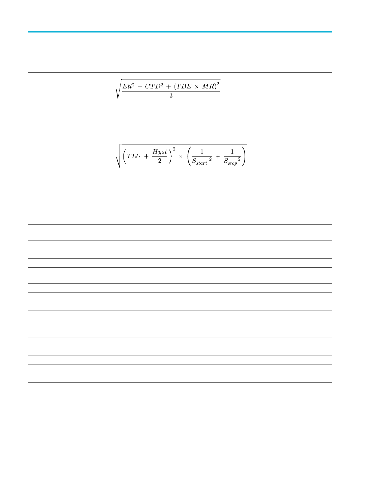
Random Measurement
Uncertainty
(FCA3000, FCA3100,
MCA3000, channels A
and B)
For measurement time ≥200 ms and Smart Freq = Auto or ON:
NOTE. This equation is the default on FCA3100 Series.
Where:
MR = Measurement reading
QE = Quantization Error
TE = Trigger Error
MT = Measurement Time
N = 800/MT with the following limits: 6 ≤ N ≤ 1000 and N<((MR/2)*MT) – 2
For FCA3100, additionally, N < M T/8 μs
For measurement time <200 ms and Smart Freq = Auto or OFF:
Specifications
Systemic Measurement
Uncertainty
(FCA3000, FCA3100,
MCA3000 channels A and B)
Where:
TBE = Timebase Error
MR = Measurement Reading
MT = Measurement Time
GTU = Gate Time Uncertainty
Ancillary Measurements Vmax, Vmin, V
Period
Mode
Range
Resolution
(FCA3000 Series)
Capable of measuring period on any of up to three inputs
Single, Average
Channel A, B: 3.3 ns to 1000 s (single, average)
Channel C (Option): 10 ns down to 330 ps, 125 ps, 70 ps, or 50 ps
100 ps (single shot) 12 digit/s (average)
Where:
MR = Measurement reading
QE = Quantization Error
TE = Trigger Error
MT = Measurement Time
p-p
FCA3000, FCA3100, and MCA3000 Series Specifications and Performance Verification 7

Specifications
Table 5: Guaranteed measurement capabilities (cont.)
Characteristics Description
Total Measurement
Uncertainty
Where:
RMU = Random Measurement Uncertainty
SMU = Systemic Measurement Uncertainty
Total Measurement
Uncertainty
(MCA3000 channel C)
Where:
RMU = Random Measurement Uncertainty
SMU = Systemic Measurement Uncertainty
stomer
er, and the only V ISIBLE unknown. There is an uncertainty in the .02 that
Random Measure
Uncertainty
(FCA3000, FCA3100,
MCA3000 Serie
and B)
ment
s, channels A
MT is driven by cu
F is the input Frequency rounded to the next GHz up
TBEisTimeBaseErrorverified in the PV
MJ is Mixer Jitt
becomes part of the .0151
For measurement time ≥200 ms and Smart Freq = Auto or ON:
NOTE. This equation is the default on FCA3100 Series.
Ancillary Measurements V
Where:
MR = Measurement reading
QE = Quantization Error
TE = Trigger Error
MT = Measurement Time
N = 800/MT with the following limits: 6 ≤ N ≤ 1000 and N<((MR/2)*MT) – 2
For FCA3100, additionally, N < MT/8 μs
For measurement time <200 ms and Smart Freq = Auto or OFF:
Where:
MR = Measurement reading
QE = Quantization Error
TE = Trigger Error
MT = Measurement Time
MAX,VMIN,Vp-p
8 FCA3000, FCA3100, and MCA3000 Series Specifications and Performance Verification

Table 5: Guaranteed measurement capabilities (cont.)
Characteristics Description
Time Interval Error (TIE)
FCA31xx only
Time Interval
Range, Nominal Calculation
Range, Smart Calculation
Resolution
(FCA3000 Series)
Minimum Pulse Width 1.6 ns
Smart Calculation Smart Time Interval determines sign (A before B or A after B)
Total M easurement
Uncertainty
Random Measurement
Uncertainty
Normalized Period Back-to-back measurements, calculated as:
TIE(k) = kT
REF–Ti
where:
= individual period back-to-back
T
i
= R eference period value
T
REF
Capable of measuring time from one event until the next. Time intervals only measurable
on the A and B channels.
6
sto+106s
6
s
0nsto+10
-10
100 ps
Where:
RMU = Random Measurement Uncertainty
SMU = Systemic Measurement Uncertainty
Specifications
ic Measurement
System
Uncertainty
Trigger Level Timing Error
(Etl)
Where:
QE = Quantization Error
TE
igger E rror for a particular edge X
=Tr
X
Where:
Etl = Trigger Level Timing Error
CTD = Channel Timing Difference
TBE = Timebase Error
MR = Measurement Result
Where:
TLU = Trigger Level Uncertainty
Hyst = Hysteresis Win
S
= Slew Rate at the trigger point for timing location X
X
dow
FCA3000, FCA3100, and MCA3000 Series Specifications and Performance Verification 9

Specifications
Table 5: Guaranteed measurement capabilities (cont.)
Characteristics Description
Positive and Negative
Pulse Width
Range 2.3 ns to 106s
Minimum Pulse Width 2.3 ns
Total Measurement
Uncertainty
Random Measurement
Uncertainty
Systemic Measurement
Uncertainty
Capable of measuring Pulse Width on A or B channels
Where:
RMU = Random Measurement Uncertainty
SMU = Systemic Measurement Uncertainty
Where:
QE = Quantiz
TE
= Trigger Error for a particular edge X
X
ation Error
Where:
Etl = Trigger Level Timing Error
CTD = Channel Timing Difference
TBE = Timebase Error
MR = Measurement Result
Trigger Level Timing Error
(Etl)
Where:
TLU = Trigger Level Uncert
Hyst = Hysteresis Window
S
= Slew Rate at the trigger point for timing location X
X
Ancillary Measurements V
Rise and Fall Time
max,Vmin,Vp-p
Capable of measuring Rise or Fall Time on A or B channels
Range 1.5 ns to 106sec.
Trigger Levels
10% and 90% of signal lev
Pulse Width 1.6 ns
Total Measurement
Uncertainty
Where:
RMU = Random Measurement Uncertainty
SMU = Systemic Measurement Uncertainty
ainty
el
10 FCA3000, FCA3100, and MCA3000 Series Specifications and Performance Verification

Table 5: Guaranteed measurement capabilities (cont.)
Characteristics Description
Random Measurement
Uncertainty
Where:
QE = Quantization Error
ror for a particular edge X
Systemic Measu
rement
Uncertainty
Trigger Level Timing Error
(Etl)
TE
= Trigger Er
X
Where:
Etl = Trigger Level Timing Error
CTD = Channel Timing Difference
TBE = Timebase Error
MR = Measurement Result
Specifications
Where: TLU = Trigger Level Uncertainty
Hyst = Hysteresis Window
= Slew Rate at the trigger po
S
X
Ancillary Measurements
Positive and Negative Duty
Slew rate, V
Capable of measuring Positi
Factor
Range 0.000001 to 0.99999
Frequency Range 0.1 Hz to 300 MHz
Total M easurement
Uncertainty
Where:
RMU = Random Measurement U
SMU = Systemic Measurement Uncertainty
Random Measurement
Uncertainty
Where:
QE = Quantization Error
TE
= Trigger Error for a particular edge X
X
int for timing location X
MAX,VMIN
ve or Negative Duty Factor on A or B c hannels
ncertainty
FCA3000, FCA3100, and MCA3000 Series Specifications and Performance Verification 11
Specifications
Table 5: Guaranteed measurement capabilities (cont.)
Characteristics Description
Systemic Measurement
Uncertainty
Where:
Etl = Trigger Level Timing Error
CTD = Channel Timing
TBE = Timebase Error
MR = Measurement Result
Trigger Level Timing Error
(Etl)
Where:
TLU = Trigger Level Uncertainty
Hyst = Hysteresis Window
= Slew Rate at the trigger point for timing location X
S
X
Ancillary Measurements Period, Pulse width
Time stamping
Time-Stamp-capable
channels
Maximum Sample Speed See GPIB specifications.
Maximum Frequency 160 MHz
Maximum Frequency to catch
each edge
Minimum Pulse Width
Timestamp Resolution
Voltage Measurement,
Channels A and B
Range 1X attenuator: –5 V to +5 V
Frequency Range
Modes V
Resolution (FCA3000 Series)
Capable of providing raw time stamp data together with pulse counts on inputs. Accessible over
programmatic interfaces only. Timestamping is not available for MCA3000 Series channel C.
FCA3000 Series: A, B, C
FCA3100, MCA3000 Series: A, B
I/O Transfer Rate determines Maximum Sample Speed.
250 kHz (FCA3000, FCA3100 Series)
2.5 ns (FCA3000, FCA3100 Series)
70 ps (FCA3000 Series)
50 ps (FCA3100 Series)
Capable of identifying positive peak and negative peak voltages
Vmax = Signal (positive peak) + Noise (pk) – 1/2 hysteresis
Vmin = Signal (negative peak) – Noise (pk) + 1/2 hysteresis
10X attenuator: –50 V to +50 V
DC,1Hzto300MHz
MAX,VMIN,Vp-p
V
is calculated from the Vmax and Vmin values. Thus it has twice the error band.
p-p
1X attenuator: 3 mV
10X attenuator: 30 mV
Difference
12 FCA3000, FCA3100, and MCA3000 Series Specifications and Performance Verification

Table 5: Guaranteed measurement capabilities (cont.)
Characteristics Description
Accuracy (5 V range)
Power
(MCA3000 Series channel C)
Power R ange -35 dBm to +10 dBm
Frequency Range
Resolution 0.01 dB m at 100 ms measuring time
Accuracy
Totalize A, B (FCA31XX Only) The instrument is capable of totalizing counts
Totalize Modes Tot A, Tot B, Tot A+B, Tot A–B
Totalize Range 1 to 1010counts
Totalize Frequency Range < 160 MHz
Totalize Controls Start: Manual or Start Arming
Ancilliary Measurements
1X Attenuator
DC, 1 Hz to 1 kHz: 1% +15 mV
1kHzto20MHz:
20 MHz to 100 MHz:
100 MHz to 300 MHz:
10X Attenuator
DC, 1 Hz to 1 kHz: 1% +150 mV
1kHzto20MHz:
20 MHz to 100 MHz:
100 MHz to 300 MHz:
Product can measure the power input to channel C
MCA3027: 0.3 GHz to 27 GHz
MCA3040: 0.3 GHz to 40 GHz
MCA3027: 0.3 GHz to 27 GHz: ±1 dBm
MCA3040: 0.3 GHz to 20 GHz: ±3 dBm
>27 GHz to 40 GHz: ±2 dBm
Stop: Manual or Stop Arming or Timed
Totalize A: A–B, A/B
Totalize B: A–B, A/B
Totalize A+B: A, B
Totalize A–B: A, B
Totalize A/B: A, B
Specifications
3% + 15 mV
10% + 15 mV
30% + 15 mV
3% + 150 mV
10% + 150 mV
30% + 150 mV
Table 6: Other available readings
Characteristic
1
Frequency Ratio
Range 10-9to 10
Lowest Input Frequency for
Correct Operation
Description
Able to provide the ratio of two input signals. Available measurements may depend upon
selected options
11
0.1 Hz
FCA3000, FCA3100, and MCA3000 Series Specifications and Performance Verification 13

Specifications
Table 6: Other available readings (cont.)
Characteristic
1
Ancillary Measurements
Phase
Range
Resolution
Maximum Usable Frequency 160 MHz
Ancillary Measurements
1
Other Available Readings do not have an accuracy specification.
Description
Frequency of either input signal
Capable of measuring Phase between the A and B channels using either as the reference
–180° to +360°
Single-cycle 0.001° up to 10 kHz, decreasing to 1° >10 MHz. Resolution can be improved by
using averaging (statistics)
Frequency (A)
Va, Vb (in dB)
Table 7: Other option capabilities
Characteristic
Frequency Burst A, B, C
(FCA3020/FCA3120)
Function
Description
Frequency and PRF of repetitive burst signals can be measured without external control
signal and with selectable start arming delay.
Frequency in burst (in Hz)
PRF (in Hz)
Range
Input A, B, C: See Frequency Spec.
Minimum Burst Duration Down to 40 ns
Minimun Pulses in Burst
Channel A or B: 3 (6 above 160 MHz)
Channel C: 3 x prescaler factor
PRF Range: 0.5 Hz to 1 MHz
Start Delay
Other Measurement:
10 ns to 2 s, 10 ns resolution
PRF
Table 8: Software functions
Characteristic
Statistics
Measurements
Display Numeric, histogram, or trend plots
Sample Size
Limit Quali fier OFF or Capture v alues above/below/inside our outside limits
Measurement Pacing, Pacing
Time Range
Auxiliary Functions; Trigger
Hold-Off, Time Delay Range
Auxiliary Functions; External
Arming
Description
Maximum, Minimum, Mean, ΔMax-Min, Standard Deviation and Allan Deviation
9
2to2x10
samples
4 μs to 500 s
20 ns to 2 s, 10 ns resolution
Provides Start and S top Arming
14 FCA3000, FCA3100, and MCA3000 Series Specifications and Performance Verification

Table 8: Software functions (cont.)
Specifications
Characteristic
Modes
Description
Start, Stop, Start and Stop Arming
Input Channels A, B, or E (rear panel)
Maximum Repetition Rate for
Arming Signal
Channel A , B: 160 MHz
Channel E: 80 MHz
Start Time Delay Range FCA3000 Series: 20 ns to 2 s, 10 ns resolution.
MCA3000 Series: 10 ns to 2 s, 10 ns resolution
Mathematics Functions
(K*X+L)/M
(K/X +L)/M
Where:
X is current reading
K, L, and M are constants
Constants set by keyboard or as frozen reference value (X
Mathematics Functions; Stored
Instrument Setups
Mathematics, Other Functions;
20 (10 can be user protected)
Instrument setups are saved/recalled from internal nonvolatile m emory
14 digits in numerical mode
Number of Displayed Digits
Table 9: Power
Characteristic
Line Power
Fuse Rating
Description
100 – 240 V
±10%, CAT II: 50 – 400 Hz ±10%: 40 W
AC
No customer accessible fuse
)
6
Table 10: I/O connectors
Characteristic
GPIB Interface Included IEEE488.2 - 1987 Interface
Functions
Modes
Interface Functions SH1, AH1, T6, L4, S R1, RL1, DC1, DT1, E2
Measurement Rate, FCA3000
Series
Measurement Rate,
FCA30xx/MCA30xx
USB Interface USB2.0, full speed
Classes USBTMC USB488 subclass
Description
All front panel accessible controls
Native Agilent 53131/132/181 command emulation. Timing and resolution not compatible
To GPIB: 2000 readings/s block, 350 readings/s individual, 4000 readings/s talker only
To Internal Memory: 250K readings/s
Internal memory size: up to 750K readings
To GPIB: 13,900 readings/s block, 650 readings/s individual, 4000 readings/s talker only
To Internal Memory: 250K readings/s, 100K readings/s with calibration on
Internal memory size: Up to 3.9 M readings with calibration off
FCA3000, FCA3100, and MCA3000 Series Specifications and Performance Verification 15

Specifications
Table 11: Displ
Characteristic
Display Type
Display Reso
ay characteristics
lution
Description
Backlit LCD Graphics screen for menu control, numerical readout, and status information
320 x 97 pixel
s
Table 12: Mechanical Characteristics
Characteristic
Dimensions
Width
Height
Depth
Weight
Net
Shipping
Description
210 mm (8.27 in)
90 mm (3.54 in)
395 mm (15.55 in)
2.7 kg (5.8 lb)
3.5 kg (7.5 lb)
Table 13: Environmental performance – Laboratory Products
Characteristic Description
Temperature
Humidity
Altitude (maximum) Operating and nonoperating: 2000 m (6500 feet)
Operating: +0 °C to +50 °C
rating: -40 °C to +71 °C
Nonope
to +30 °C (50 °F to 86 °F): 5% to 95%
+10 °C
+30 °C to +40 °C (86 °F to 104 °F): 5% to 75%
+40 °C to +50 °C (104 °F to 122 °F): 5% to 45%
16 FCA3000, FCA3100, and MCA3000 Series Specifications and Performance Verification

Performance Verification
This chapter contains performance verification procedures for the specifications
marked with the symbol. The following equipment, or a suitable equivalent, is
required to c
Table 14: Recommended Equipment
Equipment Requirements Example
Frequency
Standard
Signal source
(Function
generator)
Microwave signal
source
Digital multimeter
Accuracy 5X better than the timebase being tested
Output Amplitude ≥0.5 V
-11
6×10
required for the ultra high stability timebase
1 channel at 200 MHz or better
Signal noise at 1 V output < –40 dBc
External reference input
40 GHz operation
Frequency accuracy better than 1%
Amplitude accuracy better than 1.5 dB
Output range –50 dBm to +7 dBm
1% measurement accuracy of resistance near 1 MΩ
omplete these procedures.
rms
(1.4 V
)
p-p
Spectracom/Pendulum 6689
Frequency Standard
Tektronix AFG3251 or AFG3252
Gigatronics 2440C Signal Source with
Option 18,and Option 26C
Tektronix DMM4020
0.5% measurement accuracy on AC Volts at 10 mV
Oscilloscope 100 MHz Bandwidth, 5 mV/div and up Tektronix D PO3012 Oscilloscope
Power meter
Power splitter
Adapter
Adapter
Adapter Type N male to 2.92 m ale connector
40 GHz operation
VSWR < 1.37 at 40 G Hz
Maximum power +7 dB
Minimum power –10 dB
200MHzto40GHz
Linearity Error < ±0.35 dB from –10 dBm to +10 dBm
DC to 40 GHz
Type K connector
Male input connection
Female output connections
Insertion loss < 8.5 dB at 40 GHz SWR < 2
SMA female to SMA female
BNC to Banana Plug adapter
20 GHz operation
R&S NRVS Power Meter with
NRV-Z15 Sensor
Anritsu K241C
Tektronix part number 015-1012-XX
Tektronix part number 012-1450-XX
Fairview Microwave SM3140
FCA3000, FCA3100, and MCA3000 Series Specifications and Performance Verification 17

Performance Verification
Table 14: Recommended Equipment (cont.)
Equipment Requirements Example
Adapter
Adapter
Adapter (Qty 2) 2.92 male to SMA female connector
Adapter (Qty 2)
Cable (Qty 2) SMA male to BNC male
Cable (Qty 2) Coaxial cable, BNC male to BNC male
Cable Coaxial cable, BNC male to BNC female
Cable SMA male to SMA male cable
Cable 1 m cable with 2.92 mm male and female connector Huber & Sohner
Termination
Attenuator (Qty 2) 50 Ω 10X attenuator, ±5% accuracy
2.92 mm male to N female
Low frequency requirement
Type N male to BNC female
4GHz
40 GHz operation
2.92 male to 2.92 male connector
40 GHz operation
Coaxial BNC feedthrough terminator, 50 Ω,2W
Fairview Microwave SM3130
Fairview Microwave SM3510
Fairview Microwave SM3285
Fairview Microwave SM3242
Tektronix part number 174-3998-XX
Tektronix part number 012-0117-XX
Tektronix part number 012-0104-XX,
18 inch, or Pomona 4524-C-36,
36 inch
Tektronix part number 174-5401-XX
84119347–SF102/115K/215K/1.0M
Tektronix part number 011-0049-XX
Tektronix part number 011-0059-XX
se procedures cover all FCA3000, FCA3100, and MCA3000 series models.
The
Please ignore checks that do not apply to the specific model that you are testing.
otocopy the test record and use it to record the performance test results for
Ph
your instrument.
s an alternative, you can access an Excel spreadsheet by clicking on the
A
paperclip icon, at the left. This spreadsheet form of the test record will perform
some of the necessary calculations for you.
1. Double-click on the paperclip icon, to the left.
2. Select File > Save As in the spreadsheet File menu, and save it to a convenient
place on your desktop.
3. When you perform the Front End Characteristics procedure, enter the
measured values on the yellow Front End Characteristics tab. Calculated
values will automatically be added to the Test Record tab.
18 FCA3000, FCA3100, and MCA3000 Series Specifications and Performance Verification

Test Record
Table 15: Test record
Performance Verification
Instrument Model Number:
Instrument Serial Number:
Instrument T
imebase Option:
Date of Test:
Certificate Number:
Temperature
:
RH %:
Technician:
Instrument performance test Minimum Measured Maximum
Input Impedance
Channel A 47.5 Ω 52.5 Ω
Channel B 47.5 Ω 52.5 Ω
Front End Characteristics
Channel A
1X Noise (RMS)
1X Hysteresis Window
0mV 0.5mV
——
30 mV
1X Trigger Level Uncertainty –15 mV 15 mV
10X Noise (RMS)
10X Hysteresis Window
0mV 5mV
——
300 m V
10X Trigger Level Uncertainty –150 mV 150 m V
Channel B
1X Noise (RMS)
1X Hysteresis Window
——
0mV 0.5mV
——
30 mV
1X Trigger Level Uncertainty –15 mV 15 mV
10X Noise (RMS)
10X Hysteresis Window
0mV 5mV
——
300 m V
10X Trigger Level Uncertainty –150 mV 150 m V
Sensitivity, DC-400 MHz at 1X Attenuation
Channel A
10 Hz @ 15 m V
RMS
10 kHz @ 15 mV
200 MHz @ 15 mV
300 MHz @ 25 mV
400 MHz @ 25 mV
RMS
RMS
RMS
RMS
9.9 Hz 10.1 Hz
9.9 kHz 10.1 kHz
198 MHz 202 MHz
297 MHz 303 MHz
396 MHz 404 MHz
Channel B
10 Hz @ 15 m V
RMS
10 kHz @ 15 mV
200 MHz @ 15 mV
RMS
RMS
9.9 Hz 10.1 Hz
9.9 kHz 10.1 kHz
198 MHz 202 MH
FCA3000, FCA3100, and MCA3000 Series Specifications and Performance Verification 19

Performance Verification
Instrument performance test Minimum Measured Maximum
300 MHz @ 25 mV
400 MHz @ 25 mV
RMS
RMS
297 MHz 303 MHz
396 MHz 404 MHz
Timebase Ac
FCA3X00 Ser
MCA3X00
Quant
FCA3
FCA3
MCA
ternal Reference Clock Frequency and Sensitivity
Ex
curacy
Std (7.00E
Opt. MS (2.
Opt. HS (6
Series
Std (2.4
Opt. HS
Opt. US
ization Error
100 Series
000 Series
3000 Series
ies
–6
.00E
–7
0E
(6.00E
(1.80E
)
40E
)
0.9999930000 1.0000070000
–7
)
–8
)
0.9999997600 1.0000002400
0.9999999400 1.0000000600
0.9999997600 1.0000002400
–8
)
–8
)
0.9999999400 1.0000000600
0.9999999820 1.0000000180
——
——
——
65 ps
100 ps
100 ps
0.999999 MHz 10.000005 MHz 10.000015 MHz
4.999995 MHz 10.000005 MHz 10.000015 MHz
.999990 MHz
9
0.000005 MHz
1
0.000015 MHz
1
RMS
RMS
RMS
0 MHz Out Amplitude
1
Output Amplitude
1.0 V
——
20 FCA3000, FCA3100, and MCA3000 Series Specifications and Performance Verification

Performance Verification
Instrument performance test Minimum Measured Maximum
Channel C (If Installed)
Input Impeda
FCA3003, FC
FCA3020, FC
Frequency
FCA3X03
FCA3X2
MCA
nce
A3103, MCA3040
A3120, MCA3027
Sensitivity
100 MHz @ –
300 MHz @
2.5 GHz @
3.0 GHz
21 dBm (~20 mV
–27 dBm (~10 mV
–21 dBm (~20 mV
@ –15 dBm (~40 mV
0
z @ –21 dBm (~20 mV
250 MH
Hz @ –21 dBm (~20 mV
500 M
z @ –27 dBm (~20 mV
18 GH
Hz @ –21 dBm (~20 mV
20 G
30XX
0 MHz @ –33 dBm (~5 mV
30
GHz @ –33 dBm (~5 mV
18
0 GHz @ –29 dBm (~8 mV
2
7 GHz @ –27 dBm (~10 mV
2
40 GHz @ –23 dBm (~16 mV
–5.61 dB (0.
–5.09 dB (0.
)
RMS
)
RMS
)
RMS
)
RMS
)
RMS
)
RMS
)
RMS
)
RMS
)
RMS
)
RMS
)
RMS
)
RMS
) 40.00 GHz 40.00 GHz
RMS
100.0 MHz 100.0 MHz
300.0 MHz 300.0 MHz
2.500 GH
3.000 G
250.0 MHz 250.0 MHz
500.0 MHz 500.0 MHz
18.0
00 GHz
20.
300.0 MHz 300.0 MHz
.00 G Hz
18
0.00 GHz
2
7.00 GHz
2
524)
556)
z
Hz
0GHz
-1.84 dB (0.
–2.19 dB (0.
2.500 GH
Hz
3.000 G
0GHz
18.0
00 GHz
20.
.00 GHz
18
0.00 GHz
2
7.00 GHz
2
809)
777)
z
FCA3000, FCA3100, and MCA3000 Series Specifications and Performance Verification 21
Performance Verification
Front End Characteristics
Worksheet
The Front End Ch
are used to calculate the characteristics of the instrument. The calculations shown
in this worksheet use the line references (Ref) to indicate which measured value to
use in that calculation.
There is also a spreadsheet version of the test record, available from the paperclip
icon on Page 2-2, which will perform the calculations automatically as the
measured values are entered.
Table 16: Front End Characteristics Worksheet
Measurement Step
Ref Name
Measure:
A
Terminator Only Step 6
B First Attenuator
C Second Attenuator Step 8
D 1X Trigger Level Uncertainty
E 1X Just Triggers
F 10X Trigger Level Uncertainty
10X Just Triggers
G
H 10X Just Becomes Inaccurate
I 1X Just Becomes Inaccurate
Calculate:
J
10X Attenuator Correction A/B
K
100X Attenuator Correction A/C
L
1X Pk-Pk Noise
M 10X Pk-Pk Noise
N
1X noise (RMS) L / 2 / 3.1
1X Hysteresis Window
O
P
10X Noise (RMS) M / 2 / 3.1
10X Hysteresis Window
Q
or Calculation Value Units
Step 7
Step 14
Step 15
Step 18
Step 18
Step 21
Step 26
((I – E) / K) × 500
((H – G) / J) × 500
(((I + E) / 2) / K) × 1000
(((H + G) / 2) / J) × 1000
aracteristics procedure requires several measurements, which
Copy into
Test Record
V
V
V
Channel A Channel B
mV X
V
mV X
V
V
V
na
na
mV
mV
mV X
mV X
mV X
mV X
22 FCA3000, FCA3100, and MCA3000 Series Specifications and Performance Verification

Instrument Calibration Procedures
Instrument Ca
Instrument Warmup
Require
Internals Calibration
ments
Equipment
libration Procedures
Run the Inter
Verification, or whenever the ambient ai r temperature of the instrument changes
bymorethan5°C(9°F).
CAUTION. The FCA/MCA3X00 Series instrument can be damaged by trying
to run calibration procedures without the correct test equipment, setup, and
procedure. To avoid damage to the FCA/MCA3X00 Series instrument, do NOT
attempt to
Calibration procedures.
All FCA/MCA3X00 Series models require a 48 hour warm-up period,except
FCA models with a Standard Timebase. FCA models with a Standard Timebase
only req
No equipment is required.
nals Calibration procedure before running a Performance
perform the Timebase Calibration, Voltage Calibration, or Power
uire a 20 minute warm-up.
Procedure
Reset the Instrument
1. Disconnect all cables and inputs from the FCA/MCA3X00 Series instrument.
2. Power on the FCA/MCA3X00 Series instrument for a minimum of 20
minutes. (See page 24, Instrument Warmup Re quirements.)
3. Push User Opt -> Calibrate -> 62951413 -> Enter.
4. Push Internals.
NOTE. Only push Internals. Do not select any other calibration program
available at this point, only Internals. Doing so may void your traceability.
5. Push Start Calib.
6. The FCA/MCA3X00 Series instrument displays the Frequency A
measurement screen when the calibration is done.
After performing any procedure on an FCA/MCA3X00 Series instrument, it is a
good idea to reset the instrument to the factory defaults, to return the instrument
to a known state:
Push the User Opt button, and then select Save Recall > Setup > Recall
Setup > Default.
FCA3000, FCA3100, and MCA3000 Series Specifications and Performance Verification 23
Performance Verification
Performance V
Instrument Warmup
Requirements
erification
This procedu
all of the guaranteed specifications.
NOTE. Before starting the Performance Verification procedures, look at the
serial number sticker on the back of the FCA/MCA3X00 Series instrument to see
which timebase the instrument has; Std., Opt. MS, Opt. HS or Opt. US. N ote
the timebase type on the test record.
All FCA/MCA3X00 Series models require a 48 hour warm-up period,except
FCA models with a Standard Timebase. FCA models with a Standard Timebase
only require a 20 minute warm-up.
re tests the FCA/MCA3X00 Series instrument, to verify that it meets
Channel A and B Input Resistance
Equipment:
Digital Multimeter
Coaxial cable, BNC male to BNC male
BNCtoBananaPlugadapter
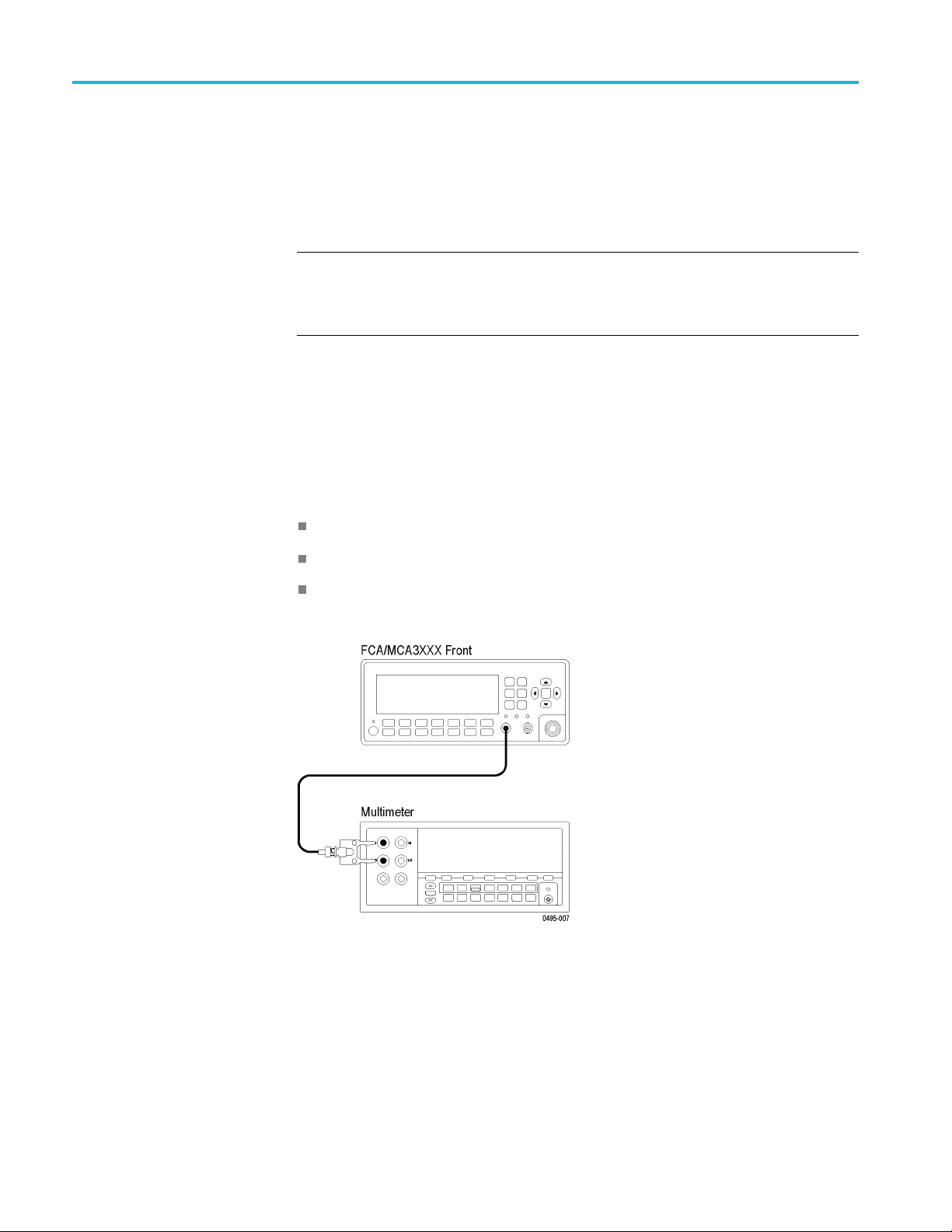
Equipment Setup
Procedure
1. Connect the equipment as shown.
2. Power on the instruments for at least 20 minutes. (See page 24, Instrument
Warmup Requirements.)
24 FCA3000, FCA3100, and MCA3000 Series Specifications and Performance Verification

Performance Verification
3. Set the Digital
Tektronix DMM4020:
a. Push the Ω butt
not
4Wire mode).
b. Push the RAN
4. On the Tektronix FCA/MCA3X00 Series instrument under test:
a. Push Input A.
b. Set the input coupling to DC.
c. Set the input impedance to 50 Ω.
d. Set the input attenuator to 1X.
5. Record t
6. Move the Coaxial cable from Input A to Input B on the FCA/MCA3X00
Series
7. On the Tektronix FCA/MCA3X00 Series instrument under test:
a. Push Input B.
b. Set the input coupling to DC.
instrument.
Multimeter to measure resistance in an autorange mode. On a
on (if necessary, push again to get to 2X4Wire mode,
GE button to select Auto Range (if not already selected).
he measured Channel A input r esistance in the test record.
8. Rec
Front End Characteristics
Th
trigger level uncertainty and 10X attenuator scale factor.
Equipment:
c. Set the input impedance to 50 Ω.
d. Set the input attenuator to 1X.
ord the measured Channel B input resistance in the test record.
is procedure checks the hysteresis band at 1X, and RMS noise. It also verifies
Function Generator
Digital Multimeter
Coaxial Cable, BNC male to BNC male
50 Ω 10X (20 dB) Attenuator (Qty 2)
50 Ω Feed Through Terminator
BNC to Banana Plug adapter
FCA3000, FCA3100, and MCA3000 Series Specifications and Performance Verification 25

Performance Verification
Equipment Setu
p
Worksheet
Procedure
This procedure uses a worksheet, as several of the characteristics must be
calculated. The worksheet is located directly after the Test Record.(See Table 16
on page 22.) As an alternative, there is a spreadsheet version of the Test Record,
available from a link on page 2-2, which will perform these calculations for you.
During this procedure you will add and remove 10X attenuators to the signal
path. When more than one attenuator is connected they may be referred to as an
attenuator stack.
1. Connect the equipment as shown. Connect the 50 Ω feedthrough terminator
to the BNC-to-Banana Plug adapter, and a ttach them to the Multimeter.
2. Power on the instrumen
Warmup Requirements.)
3. Set the Function Generator to produce a 1 V DC output. Use the following
steps to set a Tektronix AFG3251:
a. Push the More function button.
b. Push the More Waveform side menu button.
c. Push DC.
d. Push the Top Me n u panel button.
ts for at least 20 minutes.(See page 24, Instrument
e. Push the Amplitude/Level Menu side menu button.
26 FCA3000, FCA3100, and MCA3000 Series Specifications and Performance Verification

Performance Verification
f. Push Offset.
g. Adjust the offset voltage to 1V.
h. Push the Output ON button to turn on the signal output. (The button
glows green.)
4. Set the Multimeter to measure DC volts, autoranging.
5. Connect the Function Generator output to the feedthrough terminator and
BNC-to-Banana Plug adapter on the Multimeter.
6. Enter the measured Terminator Only value in the test record. This value
should be approximately 1 V.
NOTE. As you add and remove attenuators in this procedure, make sure to keep
them in t
he same sequence relative to one another and to the cable. When you
first remove an attenuator, whether you remove the one closest to the cable or the
one closest to the DUT, make sure to add/remove that same attenuator in that
same position for the rest of the procedure. If necessary, label the attenuators
to maintain the order.
7. Add th
e first 10X attenuator between the feedthrough terminator and the
coaxial cable, and enter the measured First Attenuator value in the test record.
The value should be approximately 100 mV.
8. Add the second 10X attenuator between the feedthrough terminator and the
coaxial cable, and enter the Second Attenuator measured value in the test
record. The value should be approximately 10 mV.
9. Set the Function Generator to generate a 100 Hz, 1 V
signal. On an
pp
AFG3251, use these steps:
a. Push the Sine function button.
b. Push the Frequency/Period side menu button.
ush the Frequency side menu button.
c.P
d. Use the keypad and side menu buttons to enter 100 Hz.
e. Push the Top M e n u panel button.
f. Push the Amplitude/Level Menu side menu button.
g. Push Offset.
h. Use the keypad and side menu buttons to set the offset voltage to 0mV.
i. Push the Amplitude side menu button.
j. Use the keypad and side menu buttons to set the amplitude to 1V
.
pp
FCA3000, FCA3100, and MCA3000 Series Specifications and Performance Verification 27
Performance Verification
k. Use the arrow bu
cursor to the 10 mV unit of the amplitude value so that the knob changes
the output amplitude in 10 mV increments.
l. Push the Output ON buttontoturnonthesignaloutput.
10. Move the cab
voltmeter to the Channel A input on the FCA/MCA3X00 Series instrument.
Both 10X attenuators are installed. (Do not include the 50 Ω feedthrough
termination.)
11. On the Tektronix FCA/MCA3X00 Series instrument:
a. Push the Meas button and select Freq > Freq > A.
b. Push the S
the Save/Exit buttontoreturntothemainscreen.
c. Push Inp
d. Set the input coupling to DC.
e. Set the input impedance to 50 Ω.
f. Set the input attenuator to 1X.
g. Set the Trigger mode to Man.
le and attenuator stack from the feedthrough terminator on the
ettings button, select Meas Time,enter20 ms, and then push
ut A and make the following selections:
ttons below the control knob to position the control
h. Push the Tr ig menu button, enter 0V, and push the Save/Exit button to
return to the main screen.
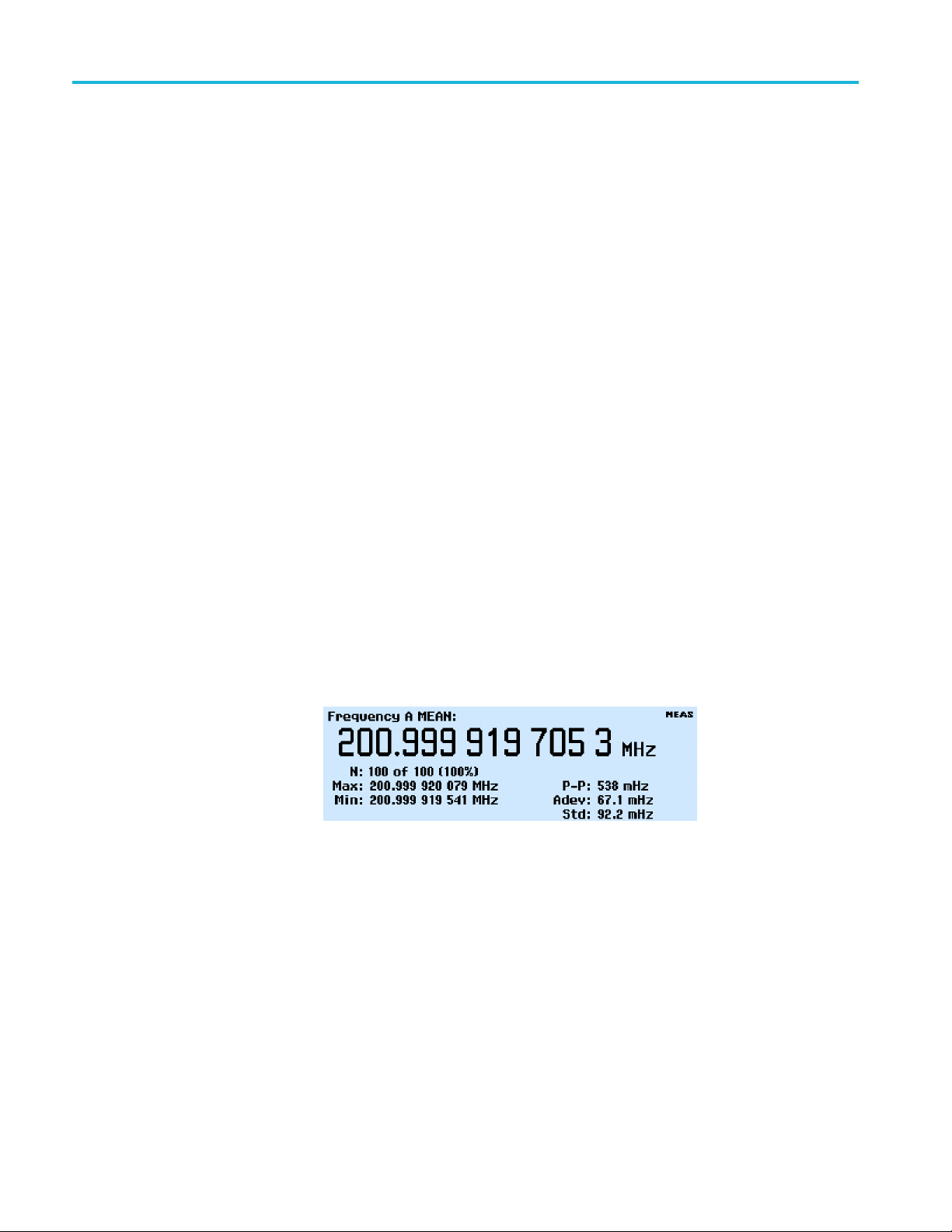
i. Push the Analyze button until you see the Numerical Analysis display,
shown here:
Figure 1: Numerical Analysis display
Note that this display has the standard deviation readout (shown as Std:)
in the lower right corner of the screen.
j. Make sure that Hold/Run is set to Run (Meas appears in the upper right
segment of the screen).
28 FCA3000, FCA3100, and MCA3000 Series Specifications and Performance Verification

Performance Verification
12. If the instrume
the Function Generator output level until the FCA/MCA3X00 Series
instrument stops counting.
NOTE. When adjusting the signal amplitude, if you hear a relay click in the
generator there will be a few cycles of incorrect data, which must be ignored.
Wait several seconds before proceeding.
13. On the Function Generator, increase the output level in 10 mV increments
until the Gate LED begins to flash. This can be an intermittent flash, it does
not have t
14. On the Tektronix FCA/MCA3X00 Series instrument, push Input A > Trig
and adjust the trigger level to read the highest possible frequency. Enter the
adjusted trigger level from the
record as 1X Trigger Level Uncertainty at 0 V.
15. On the Function Generator, reduce the signal output level until the Tektronix
FCA/MCA3X00 Series instrument does not trigger (the
flashing). Then slowly increase the Function Generator output to find the
minimum amplitude to cause the unit to count. This does not have to be an
accurate count, you are just finding the point the counter just starts to trigger,
on noise. Enter the Function Generator amplitude in the test report as 1X
Just Triggers.
nt is still triggering (the Trig LED is flashing), slowly decrease
o be regular.
FCA/MCA3X00 Series instrument into the test
Trig LED stops
16. On the Tektronix FCA/MCA3X00 Series instrument, push the Input A button
and set the input attenuation to 10X.
17. Disconnect the cable and attenuator stack from the Tektronix FCA/MCA3X00
Series instrument, remove one of the external 10X Attenuators, and reconnect
the cable and remaining attenuator to the Tektronix FCA/MCA3X00 Series
instrument.
NOTE. As you go through this procedure you will be told to remove or add
an attenuator from/to the attenuator stack. Always remove/replace the same
attenuator when you do this.
18. Repeat Steps 12 through 15, and enter the values in the test report as 10X
Trigger Level Uncertainty and Just Triggers (10X).
19. Push the Input A button to return to the Numerical Analysis screen (shows
Std).
20. Set the Function Generator signal amplitude to 3.0 Vpp.
21. Slowly decrease the Function Generator amplitude until the counter accuracy
is affected; that is, when the Std Deviation at lea st doubles (watch for a
sudden shift from mHz to Hz, as well as watching the numbers), or when the
FCA3000, FCA3100, and MCA3000 Series Specifications and Performance Verification 29

Performance Verification
frequency read
three sample periods after changing the amplitude before taking the reading.
Enter the resu
NOTE. When adjusting the signal amplitude, if you hear a relay click in the
generator there will be a few cycles of incorrect data, which must be ignored.
Wait several seconds before proceeding.
22. Disconnect the cable to the Tektronix FCA/MCA3X00 Series instrument,
replace the external 10X Attenuator removed in Step 17, and reconnect the
cable to the Tektronix FCA/MCA3X00 Series instrument.
23. On the Tektronix FCA/MCA3X00 Series instrument, push the Input A button
and set the input attenuation to 1X.
24. Reset the Trigger value to that noted in step 14, the 1X Trigger Level
Uncertainty at 0 V value.
25. Push the Save/Exit button to save the change and return to the Numerical
Analysis display.
26. Repeat steps 20 and 21, entering the result in the test record as 1X Just
Becomes Inaccurate.
out becomes noticeably incorrect. You should wait for two or
lts in the test report as 10X Just Becomes Inac curate .
27. Move the input cable and attenuator stack to the Channel B input.
28. Repeat steps 9 through 26 for Channel B.
29. Now that the measurements have been made, perform the calculations shown
at the bottom of the Front End Characteristics Worksheet. The letters in the
calculations show which reference (Ref) line to use.
If you are using the spreadsheet version of the test record, these calculations
are done for you as you enter the measurement results.
Sensitivity, DC–400 MHz at 1X Attenuation
This procedure v erifies the 1X Attenuation path sensitivity over the frequency
range.
Equipment:
Microwave Signal Generator
Function Generator
10X Attenuator
Coaxial Cable, BNC male to BNC male
30 FCA3000, FCA3100, and MCA3000 Series Specifications and Performance Verification

Performance Verification
Equipment Setup
Adapter, 2.92 m
mmaletoNfemale
Adapter, Type N male to BNC female
1
Use adapters appropriate for your test equipment and cables.
1
1
Procedure
1. Power on the instruments.
2. Wait at least 20 minutes. (See page 24, Instrument Warmup Requirements.)
3. Connect the Function Generator output through a 10X Attenuator to
Channel A on the Tektronix FCA/MCA3X00 Series instrument.
4. Set the Function Generator to produce a 10 Hz sinewave at 150 mV
(424.2 mV
). Follow these steps to set a Tektronix AFG3251:
p-p
RMS
a. Push the Sine function button.
b. Push the Frequency/Period menu button.
c. Push the Frequency menu button.
d. Use the keypad and menu buttons to set the output frequency to 10 Hz.
e. Push the Top M e nu button.
f. Push the Amplitude/Level menu button.
g. Push the –More- side menu button.
h. Push the Units side menu button, and then push the Vrms side menu
button.
FCA3000, FCA3100, and MCA3000 Series Specifications and Performance Verification 31

Performance Verification
i. Push the –More-
side menu button.
j. Push the Amplitude menu button.
k. Use the keypad and menu buttons to set the output level to 150 mV
(424.2 mV
p-p
).
l. Push the Output ON button to turn on the signal (On button glows green).
5. On the Tektronix FCA/MCA3X00 Series instrument:
a. Push the Meas button and select Freq > Freq > A.
b. Push the Settings button, select Meas Time,enter20 ms, and then push
the Save/Exit buttontoreturntothemainscreen.
c. Push the Input A button.
d. Set the input coupling to DC.
e. Set the input impedance to 50 Ω.
f. Set the input attenuator to 1X.
g. Set the Trigger mode to Man.
h. Push the Trig menu button, enter 0V, and then push the Save/Exit button
to return to the main screen.
RMS
i. Push the Analyze button as many times as needed, until you see the
Numerical Analysis display. (See Figure 1.)
6. On the Function Generator, at each of the following frequencies, verify that
the Tektronix FCA/MCA3X00 Series instrument is counting, and that the
count is accurate. Enter the frequency in the test record.
10 Hz
10 kHz
200 MHz
7. On the Function Generator, push the Output ON buttontoturnofftheoutput
signal (button goes from green to unlit).
8. On the Tektronix FCA/MCA3X00 Series instrument, disconnect the cable and
attenuator from Channel A and connect them to Channel B.
9. Repeat steps 4 through 7. Substitute Channel B for the instructions in steps
5aand5c.
10. Set the Microwave Signal Generator output to Off, set the output amplitude to
0dBm, and then set the output frequency to 300 MHz.
11. Disconnect the cable from the Function Generator and connect it to the
adapter on the Microwave Signal Generator.
12. Set the Microwave Signal Generator output to On.
32 FCA3000, FCA3100, and MCA3000 Series Specifications and Performance Verification

Performance Verification
13. Enter the Frequ
instrument as Channel B 300 MHz sensitivity in the test record.
14. Set the Microw
15. Enter the Frequency shown on the Tektronix FCA/MCA3X00 Series
instrument
16. On the Microwave Signal source, set the output to Off.
17. On the Tektronix FCA/MCA3X00 Series instrument:
a. Disconnect the cable from Channel B and connect it to Channel A.
b. Push the Meas button and select Freq > Freq > A.
18. On the Microwave Signal source, set the output to On.
19. Enter th
instrument as Channel A 400 MHz sensitivity in the test record.
20. Set the
21. Enter the Frequency shown on the Tektronix FCA/MCA3X00 Series
instr
22. On the Microwave Signal source, set the output to Off.
e Frequency shown on the Tektronix FCA/MCA3X00 Series
Microwave Signal source to 300 MHz.
ument as Channel A 300 MHz sensitivity in the test record.
ency shown on the Tektronix FCA/MCA3X00 Series
ave Signal Generator to 400 MHz.
as Channel B 400 MHz sensitivity in the test record.
Timebase Accuracy
Equipment:
uipment Setup
Eq
Frequency Standard
Coaxial cable, BNC male to BNC male
FCA3000, FCA3100, and MCA3000 Series Specifications and Performance Verification 33

Performance Verification
Procedure
1. Power on the ins
Warmup Requirements.) The frequency standard should never be turned
off but, if it has been, check the manufacturers instructions for its proper
warm-up period.
2. Connect the Frequency Standard 10 MHz output to Input A on the Tektronix
FCA/MCA3X00 Series instrument.
3. Set the Tektronix FCA/MCA3X00 Series instrument:
a. Push the Meas button and select Freq > Freq > A.
b. Push the Se
Save/Exit buttontoreturntothemainscreen.
c. Push the I
d. Set the input coupling to DC.
e. Set the input impedance to 50 Ω.
f. Set the input attenuator to 1X.
g. Set the Trigger mode to Man.
h. Push the Tr ig menu button, enter 0V, and push the Save/Exit button to
return to the main screen.
truments for at least 20 minutes. (See page 24, Instrument
ttings button, select Meas Time,enter1s, and push the
nput A button.
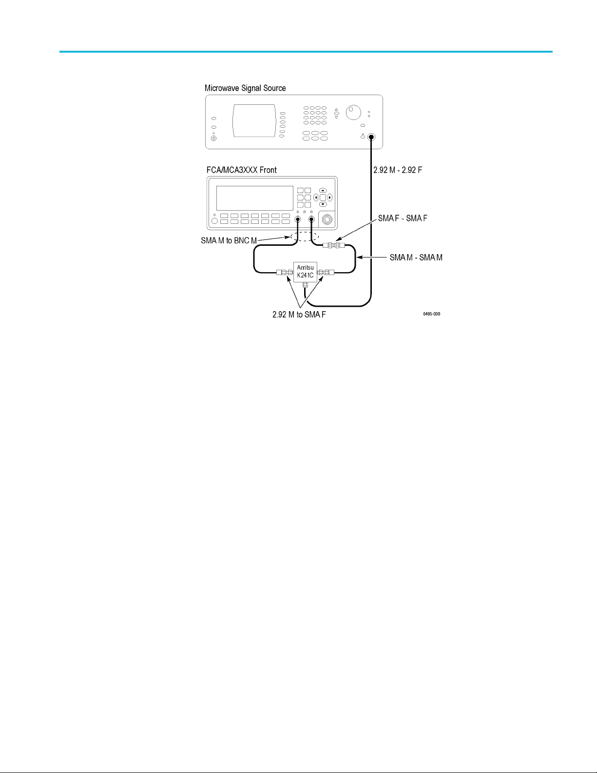
Quantization Error
Equipment:
i. Push the Value button.
j. Push
k. Using a calculator, calculate <reading>/<timebase nominal value> to get
l. Record the frequency error ratio in the test record in the appropriate
Microwave Signal Generator
Type K male to female cable
Power Splitter, Type K connectors
2.92 male to SMA female connectors (Qty 2)
SMA male to BNC male cables (Qty 2)
SMA male to SMA male cable
SMA female to SMA female adapter
the Hold/Run button to set the instrument in Hold mode.
errorasaratio.
the
cation depending upon the installed instrument timebase option (Std,
lo
or Option MS, HS, or US).
34 FCA3000, FCA3100, and MCA3000 Series Specifications and Performance Verification
Performance Verification
Equipment Setu
Procedure
p
1. Connect the equipment as shown.
ower on the instruments. Wait at least 20 minutes.
2.P
3. On the Microwave Signal Generator:
a. Set the Output to OFF.
b. Set the frequency to 300 MHz.
c. Set the outp
ut level to at least +10 dBm, not to exceed +13 dBm (2.8 V
d. Turn the Output On.
4. On the Tektronix FCA/MCA3X00 Series instrument:
a. Push the Meas button and select Time > Time Interval > A to B.
b. Push the Settings butt
on, select Meas Time,enter20 ms,andpushthe
Save/Exit buttontoreturntothemainscreen.
c. Push the Input A button.
d. Set the input coupling to DC.
e. Set slope to Falling.
f. Set the input impedance to 50 Ω.
g. Set the input attenuator to 1X.
p-p
).
h. Set the Trigger mode to Man.
FCA3000, FCA3100, and MCA3000 Series Specifications and Performance Verification 35

Performance Verification
i. Push the Trig me
nu button, enter 0.0 V, and push the Save/Exit button to
return to the main screen.
j. Push the Input B button.
k. Repeat steps d through i to set the Input B parameters.
l. Push the Value button.
5. On the Tektronix FCA/MCA3X00 Series instrument:
a. Push the Hold/Run button to put the FCA/MCA3X00 Series instrument
into Hold mode.
b. Push the Va lue button. This runs a single acquisition and returns to Hold
mode.
c. Enter the time interval measurement value in the table below.
1. 6.
2.
3. 8.
4. 9.
5.
7.
10.
e. Repeat parts b and c nine times, for a total of 10 entries in the table above.
f. Add all values together, and divide by 10 to get the mean (A1). For each
measurement, put into the A2 table the value (measurement - MEAN).
For each measurement in the A2 table, Put into the A3 table the value
A3=A2^2. Sum all of the A3 values together, divide by 9, and take the
square root (Quantization error).
A1 Value _______________
A2 Value
16
2
38
49
5
A3 Value
16
2
38
49
5
Quantization error _______________
7
10
7
10
36 FCA3000, FCA3100, and MCA3000 Series Specifications and Performance Verification
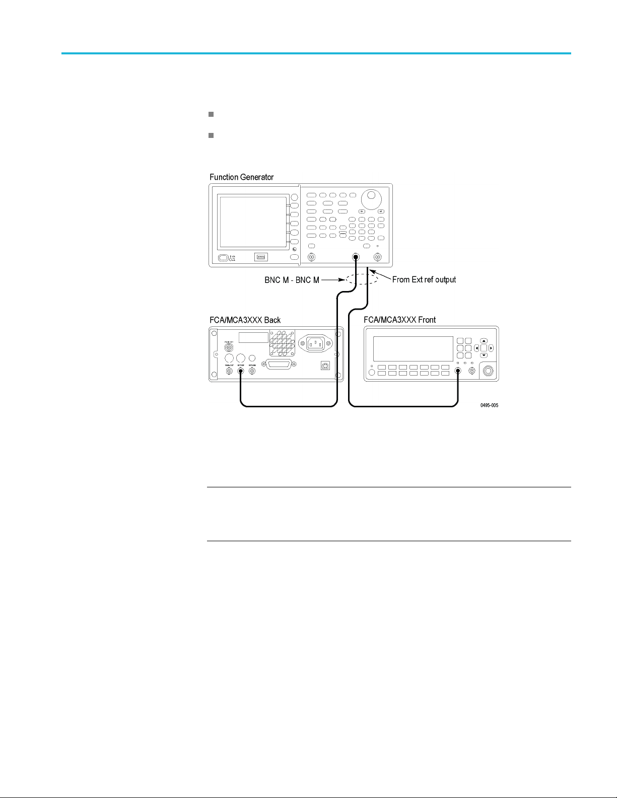
Performance Verification
External Refe
Equipment:
Equipment Setup
rence Clock Frequency and Sensitivity
Function Generator
BNC male to BNC male 50 Ω cable (24 inches) (Qty 2)
Procedure
1. Connect the equipment as shown.
2. Power on the instruments. Wait at least 20 minutes.
NOTE. To ensure that the external timebase is being used, the frequency is
intentionally offset. If the measured value does not agree with the expected value
shown in the procedure, the signal applied to the DUT External Reference input
may not be adequate.
3. Set the Function Generator to produce a 0.999999 MHz sine wave at 0.25 V
On an AFG3251, use these steps:
a. Push the Sine function button.
b. Push the Frequency/Period menu button.
c. Push the Frequency menu button.
d. Use the keypad and menu buttons to set the output frequency to
0.999999 MHz.
p-p
.
FCA3000, FCA3100, and MCA3000 Series Specifications and Performance Verification 37

Performance Verification
e. Push the Top Me n
f. Push the Amplitude/Level menu button.
g. Push the Amplitude menu button.
h. Use the keypad and menu buttons to set the output level to 0.25 Vpp.
i. Push the To p M enu button.
j. Push the Output ON button to turn o n the signal (On button turns green).
4. On the Tekt
a. Push the Meas button and select Freq > Freq > A.
b. Push the Settings button, select Meas Time,enter20 ms, and then push
the Save/Exit buttontoreturntothemainscreen.
c. Push the Input A button.
d. Set the input coupling to DC.
e. Set the input impedance to 1MΩ.
f. Set the input attenuator to 10X.
g. Set th
ronix FCA/MCA3X00 Series instrument:
eTriggermodetoMan.
u button.
h. Push the Trig menu button, enter 1.4 V, and then push the Save/Exit
on to return to the previous screen.
butt
i. Verify that Filter is set to Off.
j. Push the Settings button, select Timebase Ref, and then select Ext.
k. Push the Save/Exit button.
5. Push the Analyze button to display the Numeric Analysis screen (with Std
in lower right corner). (See Figure 1 on page 28.)
6. Enter measured frequency in the test report. (It should be close to
10.000010 MHz.)
7. Change the Function Generator frequency to 4.999995 MHz.
8. Enter measured frequency in the test report. (It should be close to
10.000010 MHz.)
9. Change the Function Generator frequency to 9.999990 MHz.
10. Enter measured frequency in the test report. (It should be close to
10.000010 MHz.)
11. Set the FCA/MCA3000 Series instrument to the factory defaults; push User
Opt > SaveRecall > Setup > Recall Setup > Default.
38 FCA3000, FCA3100, and MCA3000 Series Specifications and Performance Verification

Performance Verification
10 MHz Out Ampl
Equipment:
Setup
itude
Oscilloscope
BNC male to BNC male Cable (24 inches)
Procedure
1. Connect the as shown.
2. Power on the instruments. Wait at least 20 minutes.
3. Set the Oscilloscope:
a. Set channel 1 to 50 Ω input, 500 mV/div,andDC coupled.
b. Set the timebase to 40 nS/div.
c. Adjust the trigger for a stable display.
4. Verify that the signal amplitude on the oscilloscope is ≥1V
Enter this amplitude in the test record.
5. Verify that the output frequency is approximately 10 MHz. At 40 nS/Div two
complete sine waves should have a duration of 5 divisions.
Note that this frequenc y measurement is not sufficient to assure accuracy
of the timebase, since the oscilloscope’s timebase is less accurate than the
counter. However, it provides confidence that the output is actually 10 MHz.
Channel C (if installed) Input Impedance
Equipment:
Microwave Signal Source
(≥2.828 V
RMS
P-P
).
Power Meter with sensor
FCA3000, FCA3100, and MCA3000 Series Specifications and Performance Verification 39
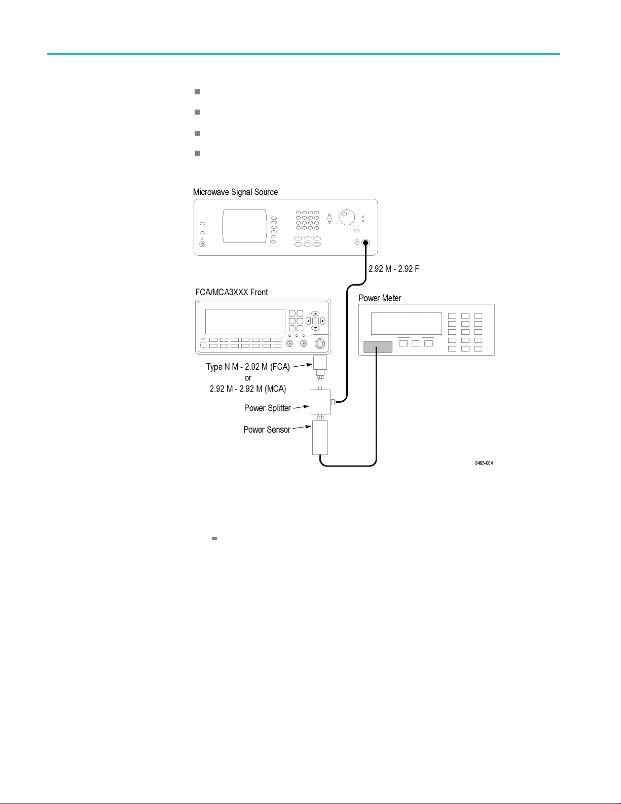
Performance Verification
Power Splitter
Setup
1m cabl
e with 2.92 mm male and female connectors
Type N male to 2.92 male adapter (FCA3X00 Series)
2.92 male to 2.92 male adapter (MCA3000 Series)
1
If installed.
Procedure
1. Connect the as shown:
FCA3100 Series instruments: Attach the type N to 2.92 mm adapter to
the FCA3100 Series instrument. Do not connect the power splitter to it
for the initial steps in the procedure. The power splitter is connected to
the adapter in Step 5.
MCA3000 Series instruments: Attach the 2.92 mm male to 2.92 mm
male adapter to the MCA3000 Series instrument. Do not connect the
power splitter to it for the initial steps in the procedure. The power splitter
is connected to the adapter in Step 5.
2. Power on the instruments. Wait at least 20 minutes. (See page 24, Instrument
Warmup Requirements.)
3. Set the Microwave signal source to output +7 dBm at 500 MHz.
40 FCA3000, FCA3100, and MCA3000 Series Specifications and Performance Verification

Performance Verification
4. Set the Power Me
input that it currently is receiving. Use these steps to set a Rohde & Schwarz
NRVS Power Meter:
a. Push W<->dBm twice, to display dBm.
b. Verify that
test record as Relative, under Input Impedance.
c. Push Unit.
d. Push REL, under the display.
e. Push ΔdB under the display.
f. Press STO under the display.
5. Connect the power splitter to the adapter on the Tektronix FCA3100 or
MCA3000 Series instrument.
NOTE. If the specified adapter is not available, it is important that the splitter
port attached to the Tektronix FCA3100/MCA3000 Series instrument has no
rs attached. The goal is to have the minimum possible load on that port
adapte
of the splitter for the first measurement. Load capacitance should be minimized.
Adapters present an unterminated stub.
ter to measure power at roughly +1 dBm relative to the
the signal is approximately +1 dBm, and log the result in the
. The length between the Type N port and the splitter must be minimized.
NOTE
Any cable length between the splitter and the Tektronix FCA3100/MCA3000 Series
instrument is likely to cause unexpected errors during the sec ond measurement.
6. Enter the relative power measured by the power meter, with the splitter
connected to the Tektronix FCA3100/MCA3000, in the Test Report:
FCA3003, FCA3103, MCA3040: Between -5.61 dB (.524) and -1.84 dB
(.809) to assure a VSWR of 2.5.
FCA3020, FCA3120, MCA3027: Between -5.09 dB (.556) and -2.19 dB
(.777)foraVSWRof2.0.
VSWR of 1:1 is at a ratio of -3.52 dB (.667).
Channel C (if installed) Frequency Sensitivity
Equipment:
Microwave Signal Source
Power Meter with sensor
1 m cable with 2.92 mm male and female connectors.
FCA3000, FCA3100, and MCA3000 Series Specifications and Performance Verification 41

Performance Verification
Setup
Type N male to 2 .
2.92 mm male to 2.92 mm male adapter (MCA3000 Series)
92 mm male adapter (FCA3100 Series)
Procedure
1. Connect the as shown. This is the same setup as the preceding step.
2. Power on the instruments. Wait at least 20 minutes. (See page 24, Instrument
Warmup Requirements.)
3. On the Tektronix FCA/MCA3000 Series instrument, push the Meas button
and select Freq > Freq > C.
4. Set the Microwave Signal Generator to output the first frequency listed below,
for the Tektronix FCA/MCA3000 Series instrument being tested.
5. Adjust the Microwave Signal Generator output so that the Power Meter shows
the amplitude listed for the frequency setting made in Step 4.
6. Enter Pass in the test record if the first four significant digits of the Tektronix
FCA/MCA3000 Series frequency readout match the microwave signal
generator’s frequency. Enter Fail if the frequency readouts do not agree.
igits after the first 4 most significant do not matter.
D
7. Repeat steps 4 through 6 for the remaining frequencies shown for the
instrument being tested.
42 FCA3000, FCA3100, and MCA3000 Series Specifications and Performance Verification

Frequency Amplitude
FCA3X03
100 MHz
300 MHz
–21 dBm (~20 mV
–27 dBm (~10 m
2.5 GHz –21 dBm (~20
3.0 GHz –15 dBm (~40
FCA3X20
250 MHz
500 MHz
–21 dBm (~
–21 dBm (~
18 GHz –27 dBm (
20 GHz –21 dBm
MCA30X
X
300 MHz
–33 dB
18 GHz –33 dB
z
20 GH
27 GH
40 G
z
Hz
–29 d
–27 d
dBm (~16 mV
–23
m(~5mV
m(~5mV
Bm (~8 mV
Bm (~10 mV
mV
mV
20 mV
20 mV
~10 mV
(~20 mV
Performance Verification
)
RMS
V
)
RMS
)
RMS
)
RMS
)
RMS
)
RMS
)
RMS
)
RMS
)
RMS
)
RMS
)
RMS
)
RMS
)
RMS
sh the User Opt button, and then select Save Recall > Recall Setup > Default
Pu
to return the instrument to the factory default settings.
• This completes the Performance Verification procedure •
FCA3000, FCA3100, and MCA3000 Series Specifications and Performance Verification 43
 Loading...