

Page 1
How-To Guide Continuous Measurements with Zero Dead-time
Continuous Measurements with Zero Dead-time
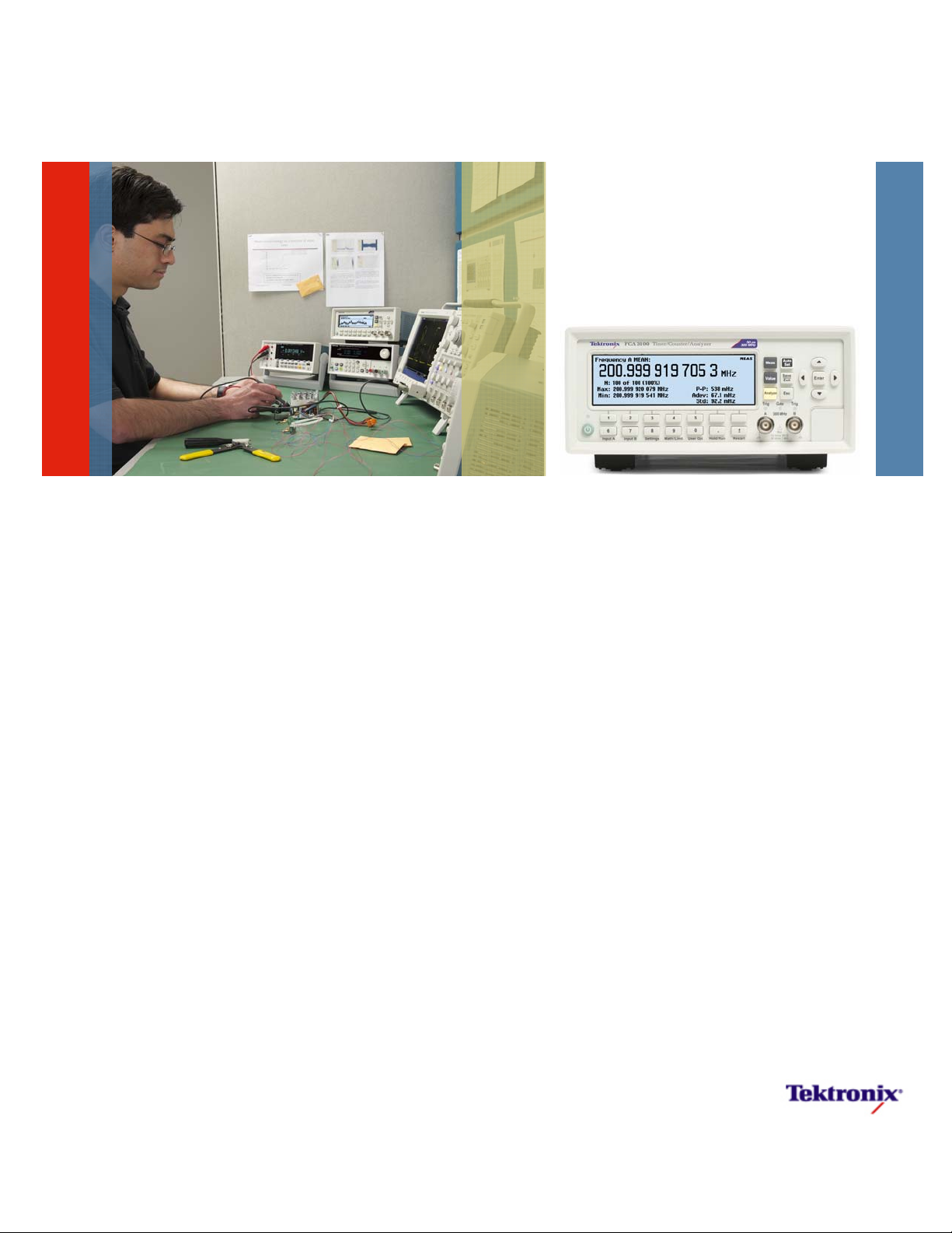
FCA3100 Series
How-To Guide
Page 2

How-To Guide Continuous Measurements with Zero Dead-time
Tektronix FCA3100 Series Timer/Counter/Analyzer introduces the concept of Continuous Data
Output with Zero Dead-time. While this How-to Guide will focus on continuous measurement for
the FCA3100 series products, it will also describe the basic functionality of measuring and
streaming data and the differences of this between the FCA3000 and FCA3100 Series products.
1. The FCA3000/FCA3100 Measuring and Output Data Transfer Modes
Let’s begin with a summary of the different measurement and output data transfer modes in the FCA3000
and FCA3100 series products.
The FCA3000 and FCA3100 Series products can operate in several different measuring and data transfer
modes:
Single (individual) measurements
Block measurements
Mode Local Operation Remote Operation
Zero-dead-time block measurements
Zero-dead-time single measurements
(FCA3100 series only)
Single
measurements
(with dead-time)
Block
measurements
(with dead-time)
Zero-dead-time
single
measurements
Zero-dead-time
block
measurements
Mode Max speed (calculated results/second)
FCA3100 FCA3000
Single measurements
(with dead-time)
FCA3100 FCA3000 FCA3100 FCA3000
Values mode Values mode READ?. INIT+FETCH?
GET INIT +TALK ONLY
Analyze mode of
any measurement
Freq BtB,
Period BtB, TIE
Freq BtB,
Period BtB,
TIE &
Analyze mode
Analyze mode of
any measurement
Not available READ?. INIT+FETCH?
Not available READ:ARR?
GET: 650/s TALK ONLY: 4000/s GET: 500/s
READ:ARR?
INIT/FETCh:ARRay?
GET INIT +TALK ONLY
INIT+FETCh:ARRay? of
Freq BtB, Period BtB, TIE
(1-timestamp/value);
Or Raw timestamp
(4-timestamp/value)
READ?.
INIT/FETCH? GET
READ ARR?
INIT/FETCH ARR?
Not available
READ ARR?
INIT/FETCH ARR? of
Raw timestamp
(4-timestamp/value)
Block measurements
(with dead-time)
Zero-dead-time
block measurements with deadtime between blocks
Continuous zero-dead-time
block measurements
READ:ARR?: 15K Sa/s READ ARR? 5K Sa/s
READ:ARR?: 15K Sa/s, 250K Sa/s
to internal memory of 3.75MB
ARM:COUNT INF
READ:ARRay:? 10K Sa/s
2 www.tektronix.com/frequencycounter
READ:ARR?: 15K Sa/s, 250K Sa/s
to internal memory of 750KB
Not available
Page 3

How-To Guide Continuous Measurements with Zero Dead-time
Single Measurements
READ?
INIT+FETCH?
GET
Single measurements mean that you do one measurement at a time and transfer to the display and to the
data outputs (GPIB or USB). This mode has a dead time between measurements of approx. 2 ms, when you
trigger the counter’s individual measurements, one by one, via the GET command (Group Execute Trigger),
from the connected controller. The internal measurement memory buffer is not involved in this mode.
Using the above commands single measurements, you can control exactly when you want to initialize (start)
the measurement. The communication process is simplified:
Controller talker /FCA3000 or FCA3100 listener: “start measurement” (GET)
Controller talker / FCA3000 or FCA3100 listener: “send result” (FETCH?)
FCA3000 or FCA3100 talker/ Controller listener: “sending result data”
Controller talker / FCA3000 or FCA3100 listener: “start next measurement” (GET) …
FCA3100: In addition to the FCA3000 modes, the FCA3100 has an additional output mode;
Talker only (SYSTem:TALKonly ON)
Talker only differs from the GET-triggered individual measurements in that the counter will be triggered once
and after that the counter will output measurement data at the highest possible rate, without waiting for
subsequent trigger commands (GET) from the controller. This reduces the transfer overhead since the
controller is not taking control between the measurements. The controller cannot initialize individual
measurements and the measurement data continues to be sent until the controller stops the transfer via the
Interface Clear command or by pressing the ESC key on the counters front panel.
The dead-time between measurements in this “real-time” transfer mode is <250 microseconds. To reach this
throughput rate, the communication process is simplified:
Controller talker /FCA3000 listener: “go to Talker only mode and start measurement”
FCA3000 talker/ Controller listener: “sending result data”
FCA3000 talker/ Controller listener: “sending result data”
Etc…
3 www.tektronix.com/frequencycounter
Page 4

How-To Guide Continuous Measurements with Zero Dead-time
Block Measurements
READ:ARR?
INIT + FETCH:ARR?
Block measurements mean that you set up a certain measurement function, e.g. frequency, and trigger a
block measurement sequence from the controller. Then the individual measurement results are transferred
one-by-one to the internal memory and stored, until the set number of samples has been reached. After that
the memory contents can be sent to the controller using the FETCH ARRAY command.
The dead-time between measurements is significantly smaller, only 4-8 microseconds. To reduce the dead
time to a minimum, you can for example disable calibration of interpolators (CAL:INT:AUTO OFF). To
maximize throughput you can also turn off the display (DISP:ENAB OFF) and use Packed data format
(FORM:PACK).
Using these modes of fetching data, you do a block transfer and cannot see the individual measurements
until the whole block is received. You can control via SW exactly when you want to initialize (start) the block.
The procedure for block measurements in the FCA3000 is pure sequential. First you measure and store ALL
values in the block in internal memory, then all measurements in the block are processed (calculated and
formatted), and finally the block is transferred to the PC. The measurement function can be any standard
function with dead time (e.g. Frequency, Period, Vp-p) or the raw time-stamping function (zero-dead-time).
This means there is always a gap of data due to the dead time between blocks in the data output, even if
individual blocks contain zero-dead-time data. In the FCA3000, true zero-dead-time measurements can only
be made up to 750K Samples (internal memory limit), after that there must be a gap in the data.
Zero Dead-time Data
Measure Gap in the data Gap in the data
Process
Transfer
4 www.tektronix.com/frequencycounter
Page 5

How-To Guide Continuous Measurements with Zero Dead-time
Zero Dead-Time Single Measurements
Only the FCA3100 features zero-dead-time single measurements, accessible from both the front panel in
local operation, as well as in remote bus operation. There are three pre-defined measurements; frequency
back-to-back, period back to back and TIE (Time Interval Error).
In frequency or period back-to-back you read the number of elapsed input trigger events or input cycles (Ni)
and the elapsed time (Ti) at intervals defined via the measuring time setting, every time you read the elapsed
events and time, you calculate the Frequency or Period on-the-fly as:
N
Freq (i) = Per (i) = TIE (i) = T
T
– N
i
– T
i
i-1
i-1
T
N
– T
i
i-1 Ni
– T0 –
i
– N
i
i-1 FREF
– N
0
Note that the Frequency value is always, per definition, the average number of cycles/s during the
measurement time. When measuring frequency, the input signal is divided by 2 before it is time-stamped,
which means the minimum frequency measurement time is over 2 cycles.
Period back-to-back and TIE has no input divider, and is a single period as long as N
case for input frequencies up to approximately 250 KHz. At higher frequencies, up to 160 MHz, the value is
= N
i
+ 1. This is the
i-1
the average period back-to-back.
Zero Dead-Time Block Measurements (Raw Time-stamping Data)
Both FCA3100 and FCA3000 series products perform zero-dead-time “raw” time-stamping measurements as
a block measurement function only, which is not accessible from the front panel. From the GPIB or USB bus
you set up a certain block sizes, select a pacing time from 4 microseconds and up, and start the timestamping measurement (FUNC:TSTA). This mode will then store the number of accumulated and timestamped input trigger events, in groups of 4, without losing any single cycle up to 160 MHz input signals.
[E(i),Tp1(i)] [E(i)+1,Tp2(i)] [E(i+1),Tp1(i+1)] [E(i+1)+1,Tp2(i+1)]
[0,Tn1(i)] [0,Tn2(i)] [0,Tn1(i+1)] [0,Tn2(i+1)]
Event Event Event Event
no E(i) no E(i+1) no E(i)+1 no E(i+1)+1
E(i) is the i:th sample of accumulated input cycles (ALL trigger events are counted and accumulated up to
160 MHz on input A or B,). E(i)=0 for the negative slopes, and the accumulated number of input cycles for
the positive slope.
Tp1(i) is the timestamp of the first positive trigger event
Tp2(i) is the timestamp of the second positive trigger event
Tn1(i) is the timestamp of the first negative trigger event
Tn2(i) is the timestamp of the second negative trigger event
5 www.tektronix.com/frequencycounter
Page 6

How-To Guide Continuous Measurements with Zero Dead-time
Please note that the first trigger event that occurs after the pacing time, may be a negative as well as a
positive trigger slope, so the sequence of the 4 timestamps may be:
pos – neg – pos – neg OR neg – pos – neg – pos .
The way to identify this is to look at the event number which is 0 for negative slopes and is a positive integer
for positive slopes.
In addition to the FCA3000 raw time-stamping mode, the FCA3100 can also measure Frequency and Period
Back-to-Back plus TIE, as zero-dead-time block measurements.
Just like normal block array measurements, this measurement can continue at maximum speed a limited
time until the internal memory buffer is filled, after 3.75M Samples (FCA3100) respectively 750k Samples
(FCA3000). After that the memory must be read and emptied before the next block of zero-dead-time data
can be measured again.
The FCA3100 can also make continuous “streaming” measurements of zero-dead-time data for an unlimited
time, as described below.
2. Continuous Streaming Output Mode
This unique FCA3100 output mode is basically a normal block measurement mode, however with the
exception that there are parallel processes for storing data in internal memory, processing stored data and
outputting data. Furthermore the block can have an unlimited size in FCA3100.
Zero dead-time data (<10K measurements/s)
Measure
Process
Transfer
Continuous measurements come in two flavors "Fetch on the Fly" and "Overwrite Mode" as described below.
Fetch on the Fly
This is simply the ability the fetch the results from a normal block measurement that fits in the buffer while it
is still running. One thing to consider though is that while the measurement hasn't finished, you may not
know how many samples are actually available for fetching. So, you use the FETC:ARR? MAX functionality
(see below).
Overwrite Mode
This is the case when you specify a larger total number of measurements than will fit in the memory, that is
>3.75M samples. As the buffer fills up, old values are overwritten with the new ones. This is done in such a
way that it should always (with reasonable measurement speed) be safe to fetch on the fly. That is, the data
that is overwritten should never be the data that is in progress of being fetched.
For almost all measurement functions the method used is the following. The memory buffer is divided into six
segments, each of which is at any one time dedicated to some particular usage (segments where data is
being fetched from and segments where new data is written to). The roles of the segments can be switched
around as needed.
6 www.tektronix.com/frequencycounter
Page 7

How-To Guide Continuous Measurements with Zero Dead-time
As long as the fetching speed more or less keeps up with the measurement speed, this works out much the
same as a regular circular buffer would do. But when you do not fetch sufficiently fast, or when you stop the
measurement and the buffer contains a lot of un-fetched data, there is always one or two segment's with
valid newest result data remaining in the buffer, i.e. between one sixth and one third of the buffer (600K to
1200K measurements).
If the instrument is set up to measure faster than it can handle in overwrite mode, you will eventually end up
with invalid data in the buffer. Most often invalid timestamps, but also invalid measurement results can
occur. Internal tests will detect when this happens, and abort the measurement and put a -321, "Storage
fault" error in the error queue, indicating that the buffer contents can't be trusted (but data is still available for
fetching).
The measurement speed limit in overwrite mode depends on a lot of factors, including for example how fast,
and in what way, the user fetches data on the fly. For this reason it's hard to set any firm rules for
measurement speed recommendation.
Currently, one limit is enforced; in overwrite mode the pacing time used is minimum 50 microseconds,
regardless of actual setting. This is to prevent the user from “choking” the instrument.
Practical tests show that data capture rates of >10K Sa/s is likely to cause invalid data at some point during a
long measurement. To be on the safe side, set a pacing time of more than 100 microseconds, with some
margin. Measurements with more complex calculations such as Phase, requires longer pacing time than
simpler measurements such as Period Single.
3. New SCPI Commands or Changed Behavior in FCA3100
FETCh:ARRay? <number of samples> | MAX (FCA3100 only)
When specifying <number of samples>, the instrument will wait until that number is available before
responding. This could result in long waits if the measurement doesn't proceed as expected.
When using the "MAX" parameter, the instrument will respond immediately with as many samples as
currently possible. The number of samples in the response is limited by the number of un-fetched samples
currently remaining in the buffer and the FORMAT:SMAX setting.
Error; -230,"Data corrupt or stale", is generated when there is no valid sample(s) to fetch at all from the
buffer.
Error -224,"Illegal parameter value" error is generated if you try to fetch a larger number of samples than
remains to fetch in the buffer. This includes also the case of using the "MAX" parameter when already at the
end of the buffer, and you have already fetched all samples.
7 www.tektronix.com/frequencycounter
Page 8

How-To Guide Continuous Measurements with Zero Dead-time
ABORt
ABORT no longer invalidates already finished results when breaking an array measurement. This means you
can now fetch the partial result after the abort.
FORMat:SMAX <number>
Where “number” is any integer between 4 and 10000. Default setting is 10000 (not affected by *RST). This
command is intended for use with any controller or application program that have problems with reading
large amounts of data, but where the FETC:ARR? MAX functionality is wanted. To query the actual setting
use:
FORMat:SMAX?
When using the "MAX" parameter, the instrument should always respond within a predictable time. Actual
response time depends primarily on the number of samples in the response and the FORMat settings used
(ASCii being particularly slow, REAL is fast and PACKed is fastest), and to some extent the actual
measurement function. When no new measurement since the latest fetch is available in the buffer (and not
at the end of it), FETC:ARR? MAX will give a "zero samples" response, ie empty string in case of format
ascii, and an empty binary data packet ("#10") in the case of format real or packed.
ARM:COUNt <number> | INFinity
ARM:COUNt?
The "INF" parameter is available in CNT91 only. It will cause the arm loop to continue endlessly. (Note: The
timestamp counter will overflow after approx 107 days of non-aborted operation, something that must be
taken care of in the application SW, if it is important to run continuously for more the 3 months.) When set to
INFinity, the query responds with "INF" (without the quotes).
Talker Only Mode
To switch on talker only mode:
SYSTem:TALKonly ON
Since now the FCA3100 will be talker “forever”, and will not listen to any programming command from the
controller via the normal handshake lines, there is no command “SYST:TALK OFF” available. Once you have
sent the command SYST:TALK ON to the counter, the FCA3100 will no longer respond to normal commands
via the data lines in the GPIB interface
To switch off Talker Only mode, you use the ESC key (C) on the front panel alternatively send an Interface
Clear (IFC) over GPIB.
Further settings to implement for successful high-speed talker only transfer are:
DISPlay:ENABle OFF.
FORMat REAL or FORMat PACKed.
ARM:COUNt 1
TRIGger:COUNt 1
INIT:CONT ON.
8 www.tektronix.com/frequencycounter
Page 9

How-To Guide Continuous Measurements with Zero Dead-time
The measurement function can be any except the following:
Period average (smart calculation)
Frequency (smart calculation)
Time Interval (smart calculation)
Time-stamping
Voltage
Totalize
This means that Frequency BtB and Period BtB is OK, but not “smart” frequency where a regression line
fitting between several time-stamped data is used to improve the basic resolution.
9 www.tektronix.com/frequencycounter
Page 10

Contact Tektronix:
ASEAN / Australasia (65) 6356 3900
Austria 00800 2255 4835*
Balkans, Israel and other ISE Countries +41 52 675 3777
Belgium 00800 2255 4835*
Brazil + 55 (11) 3759 7600
Canada 1-800-833-9200
Central East Europe, Ukraine and the Baltics +41 52 675 3777
Central Europe & Greece +41 52 675 3777
Denmark +45 80 88 1401
Finland +41 52 675 3777
France 00800 2255 4835*
Germany 00800 2255 4835*
Hong Kong 400-820-5835
India 000-800-650-1835
Italy 00800 2255 4835*
Japan 81 (3) 6714-3010
Luxembourg +41 52 675 3777
Mexico, Central/South America & Caribbean (52) 56 04 50 90
Middle East and Africa +41 52 675 3777
The Netherlands 00800 2255 4835*
Norway 800 16098
People’s Republic of China 400-820-5835
Poland +41 52 675 3777
Portugal 80 08 12370
Republic of Korea 001- 800-8255-2835
Russia & CIS +7 (495) 7484900
South Africa +41 52 675 3777
Spain 00800 2255 4835*
Sweden 00800 2255 4835*
Switzerland 00800 2255 4835*
Taiwan 886 (2) 2722-9622
United Kingdom & Ireland 00800 2255 4835*
USA 1-800-833-9200
European toll-free number. If not accessible, call: +41 52 675 3777
Contact List Updated 25 May 2010
For Further Information
Tektronix maintains a comprehensive, constantly expanding
collection of application notes, technical briefs and other
resources to help engineers working on the cutting edge of
technology. Please visit www.tektronix.com
Copyright © 2010, Tektronix. All rights reserved. Tektronix products are
covered by U.S. and foreign patents, issued and pending. Information in this
publication supersedes that in all previously published material. Specification
and price change privileges reserved. TEKTRONIX and TEK are registered
trademarks of Tektronix, Inc. All other trade names referenced are the service
marks, trademarks or registered trademarks of their respective companies.
9/2010 WWW 3CW-25883-1
 Loading...