

Page 1

x
FCA3000 and FCA3100 Series Timer/Counter/Analyzer
MCA3000 Series Microwave Counter/Analyzer
ZZZ
Quick Start User Manual
*P071278701*
071-2787-01
Page 2

Page 3

xx
FCA3000 and FCA3100 Series Timer/Counter/Analyzer
MCA3000 Series Microwave Counter/Analyzer
ZZZ
Quick Start User Manual
www.tektronix.com
071-2787-01
Page 4

Copyright © Tektronix. All rights reserved. Licensed software products are owned by Tektronix or its subsidiaries or suppliers, and are
protected by na
tional copyright laws and international treaty provisions.
Tektronix pro
previously published material. Specifications and price change privileges reserved.
TEKTRONIX and TEK are registered trademarks of Tektronix, Inc.
LabVIEW, National Instruments, NI, and SignalExpress are trademarks of National Instruments.
TimeView is a trademark of Pendulum Instruments AB .
ducts are covered by U.S. and foreign patents, issued and pending. Information in this publication supersedes that in all
Contacting Tektronix
Tektronix, Inc.
14150 SW Karl Braun Drive
P.O. Box 500
Beaverton, OR 97077
USA
For product information, sales, service, and technical support:
In North America, call 1-800-833-9200.
Worldwide, visit www.tektronix.com to find contacts in your area.
Page 5

Warranty
Tektronix warrants that this product will be free from defects in materials and workmanship for a period of three (3) years from the date
of shipment. If any such product proves defective during this warranty period, Tektronix, at its option, either will repair the defective
product without charge for parts and labor, or will provide a replacement in exchange for the defective product. Parts, modules and
replacement products used by Tektronix for warranty work may be new or reconditioned to like new performance. All replaced
parts, modules and products become the property of Tektronix.
In order to obtain service under this warranty, Customer must notify Tektronix of the defect before the expiration of the warranty period
and make suitable arrangements for the performance of service. Customer shall be responsible for packaging and shipping the
defective product to the service center designated by Tektronix, with shipping charges prepaid. Tektronix shall pay for the return of the
product to Customer if the shipment is to a location within the country in which the Tektronix service center is located. Customer shall
be responsible for paying all shipping charges, duties, taxes, and any other charges for products returned to any other locations.
This warranty shall not apply to any defect, failure or damage caused by improper use or improper or inadequate maintenance and
care. Tektronix shall not be obligated to furnish service under this warranty a) to repair damage resulting from a ttempts by personnel
other than Tektronix representatives to install, repair or service the product; b) to repair damage resulting from improper use or
connection to incompatible equipment; c) to repair any damage or malfunction caused by the use of non-Tektronix supplies; or
d) to service a product that has been modified or integrated with other products when the effect of such modification or integration
increases the time or difficulty of servicing the product.
THIS WARRANTY IS GIVEN BY TEKTRONIX WITH RESPECT TO THE PRODUCT IN LIEU OF ANY OTHER WARRANTIES,
EXPRESS OR IMPLIED. TEKTRONIX AND ITS VENDORS DISCLAIM ANY IMPLIED WARRANTIES OF MERCHANTABILITY OR
FITNESS FOR A PARTICULAR PURPOSE. TEKTRONIX’ RESPONSIBILITY TO REPAIR OR REPLACE DEFECTIVE PRODUCTS
IS THE SOLE AND E XCLU S IVE REMEDY PROVIDED TO THE CUSTOMER FOR BREACH OF THIS WARRANTY. TEKTRONIX
AND ITS VENDORS WILL NOT BE LIABLE FOR ANY INDIRECT, SPECIAL, INCIDENTAL, OR CONSEQUENTIAL DAMAGES
IRRESPECTIVE OF WHETHER TEKTRONIX OR THE VENDOR HAS ADVANCE NOTICE OF THE POSSIBILITY OF SUCH
DAMAGES.
[W4 – 15AUG04]
Page 6

Page 7

Table of Contents
General Safety Summary ...... . . . . . .... . . . . . . ... . . . . . . .... . . . . . .... . . . . . . ... . . . . . . .... . . . . . ..... . . . . . .... . . . . . . ... . . . . . . .... . . . . . ... . iii
Compliance I
Preface............................................................................................................................... viii
Installation.............................................................................................................................. 1
Getting Acquainted with Your Instrument.. . . . . . . ... . . . . . . .... . . . . . . ... . . . . . . ... . . . . . . .... . . . . . . .... . . . . . . ... . . . . . . ... . . . . . . .... . . . . . .3
Application Examples................................................................................................................. 12
Conn
nformation ............................................................................................................... v
EMC Compliance................................................................................................................. v
Safety Compliance ............................................................................................................... vi
Environmen
Key Features ................................................................................................................... viii
Documenta
Conventions Used in This Manual.... . . . . . . .... . . . . . . ... . . . . . . ... . . . . . . ... . . . . . . .... . . . . . ..... . . . . . .... . . . . . . ... . . . . . . ... . . . . . . . ix
Unpacking
Operating Considerations........................................................................................................ 1
Powering the Instrument Onand Off............................................................................................ 2
Function
Front Panel .. . . . . . . . .... . . . . . . .... . . . . . . ..... . . . . . . .... . . . . . . .... . . . . . . . ... . . . . . . . ... . . . . . . . .... . . . . . . .... . . . . . . ..... . . . . . . .... . .. 3
Rear Pan
Input Connectors . . . .... . . . . . . ... . . . . . . ... . . . . . . ... . . . . . . ... . . . . . . .... . . . . . .... . . . . . .... . . . . . . ... . . . . . . ... . . . . . . ... . . . . . . ... . . . . . .5
Controls........................................................................................................................... 6
Main Sc
Restore Default Settings ........................................................................................................ 12
Basic M
Math Measurement ............................................................................................................. 13
Limit Testing..................................................................................................................... 13
Two-C
Input C Measurements . . . . . ..... . . . . . . .... . . . . . . .... . . . . . . .... . . . . . . .... . . . . . . ..... . . . . . . ... . . . . . . . ... . . . . . . . .... . . . . . . .... . . . . . 15
Save an Instrument Setup ...................................................................................................... 16
ectivity........................................................................................................................... 18
tal Considerations.................................................................................................. vii
tion ................................................................................................................... ix
the Instrument ....................................................................................................... 1
al Check................................................................................................................. 2
el ....................................................................................................................... 4
reen...................................................................................................................... 9
easurements............................................................................................................ 12
hannel Measurements .... . . . . . . .... . . . . . . .... . . . . . . .... . . . . . . ..... . . . . . . ... . . . . . . . ... . . . . . . ..... . . . . . . .... . . . . . . .... . . . . 15
Table of Content
s
FCA3000, FCA3100, and MCA 3000 Series Quick Start User Manual i
Page 8

Table of Content
s
ii FCA3000, FCA3100, and MCA3000 Series Quick Start User Manual
Page 9

General Safety S
ummary
General Safet
Review the following safety precautions to avoid injury and prevent damage to this product or any products connected to it.
To avoid potential hazards, use this product only as specified.
Only qualified personnel should perform service procedures.
While using this product, you may need to access other parts of a larger system. Read the safety sections of the other
component manuals for warnings and cautions related to operating the system.
To Avoid Fire or Personal Injury
Use proper power cord. Use only the power cord specified for this product and certified for the country of use.
Connect and disconnect properly. Do not connect or disconnect probes or test leads while they are connected
to a voltag
Ground th
shock, the grounding conductor must be connected to earth ground. Before making connections to the input or output
terminals of the product, ensure that the product is properly grounded.
Observe all terminal ratings. To avoid fire or shock hazard, observe all ratings and markings on the product. Consult the
product
The inpu
e source.
e product.
manual for further ratings information before making connections to the product.
ts are not rated for connection to mains or Category II, III, or IV circuits.
y Summary
This product is grounded through the grounding conductor of the power cord. To avoid electric
Do not ap
Power d
must remain accessible to the user at all times.
ply a potential to any terminal, including the common terminal, that exceeds the maximum rating of that terminal.
isconnect.
The power cord disconnects the product from the power source. Do not block the power cord; it
Do not operate without covers. Do not operate this product with covers or panels removed.
Do not operate with suspected failures. If you suspect that there is damage to this product, have it inspected by
qualified service personnel.
Avoid exposed circuitry. Do not touch exposed connections and components when power is present.
Do not operate in wet/damp conditions.
Do not operate in an explosive a tmosphere.
Keep product surfaces clean and dry.
Provide proper ventilation.
per ventilation.
pro
Refer to the manual’s installation instructions for details on installing the product so it has
FCA3000, FCA3100, and MCA 3000 Series Quick Start User Manual iii
Page 10

General Safety S
Terms in This Manual
These terms may appear in this manual:
WARNING. Warning statements identify conditions or practi ces that could r esult in injury or loss of life.
CAUTION. Caution statements identify conditions or practices that could result in damage to this product or other property.
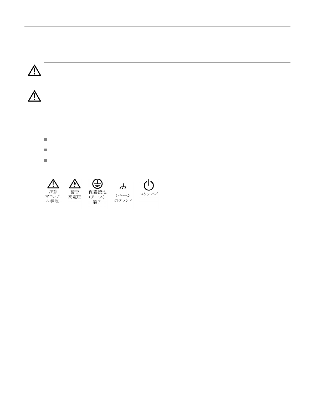
Symbols and Terms on the Product
These terms may appear on the product:
DANGER indicates an injury hazard immediately accessible as you read the marking.
WARNING indicates an injury hazard not immediately accessible as you read the m arking.
CAUTION indicates a hazard to property including the product.
The following symbol(s) may appear on the product:
ummary
iv FCA3000, FCA3100, and MCA3000 Series Quick Start User Manual
Page 11

Compliance Info
rmation
Compliance In
This section lists the EMC (electromagnetic compliance), safety, and environmental standards with which the instrument
complies.
EMC Compliance
EC Declarati
Meets intent of Directive 2004/108/EC for Electromagnetic Compatibility. Compliance was demonstrated to the following
specifications as listed in the Official Journal of the European Communities:
EN 61326-1:2006, EN 61326-2-1:2006. EMC requirements for electrical equipment for measurement, control, and
laborator
CISPR 11:2
IEC 61000
IEC 61000
IEC 61000
IEC 6100
IEC 6100
IEC 6100
on of Conformity – EMC
123
yuse.
003. Radiated and conducted emissions, Group 1, Class A
-4-2:2001. Electrostatic discharge immunity
-4-3:2002. RF electromagnetic field immunity
-4-4:2004. Electrical fast transient/burst immunity
0-4-5:2001. Power line s urge immunity
0-4-6:2003. Conducted RF immunity
0-4-11:2004. Voltage dips and interruptions immunity
formation
4
4
5
EN 61000-3-2:2006. AC power line harmonic emissions
EN 6100
0-3-3:1995.
Voltage changes, fluctuations, and flicker
European contact.
Tektronix UK, Ltd.
Western Peninsula
Western Road
Bracknell, RG12 1RF
1
This product is intended f or use in nonresidential areas only. Use in residential areas may cause electromagnetic interference.
2
Emissions which exceed the levels required by this standard may occur when this equipment is connected to a test object.
3
For compliance with the EMC standards listed here, high quality shielded interface cables should be used.
4
With a 10 MHz 0.1 Vp-p sine wave signal applied to the A or B input channels, the instrument’s frequency readout value can
typically vary up to ±1 Hz beyond the inherent base variance, when the instrument is subjected to the fields and signals as defined
in the IEC 61000-4-3 and IEC 61000-4-6 tests.
5
Performance Criterion C applied at the 70%/25 cycle Voltage-Dip and the 0%/250 cycle Voltage-Interruption test levels
(IEC 61000-4-11).
FCA3000, FCA3100, and MCA 3000 Series Quick Start User Manual v
Page 12

Compliance Info
rmation
Australia / New Zealand Declaration of Conformity – E MC
Complies with the EMC provision of the Radiocommunications Act per the following standard, in accordance with ACMA:
CISPR 11:2003. Radiated and Conducted Emissions, Group 1, Class A, in accordance with EN 61326-1:2006 and
EN 61326-2-1:2006.
Australia / New Zealand contact.
Baker & McKenzie
Level 27, AMP Centre
50 Bridge St
Sydney NSW 2000, Australia
reet
Safety Compliance
EC Declaration of Conformity – Low Voltage
Compliance was demonstrated to the following specification as listed in the O fficial Journal of the European Communities:
Low Volta
ge Directive 2006/95/EC.
EN 61010-
1: 2001. Safety requirements for electrical equipment for measurement control and laboratory use.
U.S. Nationally Recognized Testing Laboratory Listing
UL 61010-1:2004, 2ndEdition. Standard for electrical measuring and test equipment.
Canadian Certification
CAN/CSA-C22.2 No. 61010-1:2004. Safety requirements for electrical equipment for measurement, control, and
laboratory use. Part 1.
tional Compliances
Addi
IEC 61010-1: 2001. Safety requirements for electrical equipment for measurement, control, and laboratory use.
Equipment Type
t and measuring equipment.
Tes
Safety Class
Class 1 – grounded product.
vi FCA3000, FCA3100, and MCA3000 Series Quick Start User Manual
Page 13

Compliance Info
rmation
Pollution Degree Description
A measure of the contaminants that could occur in the environment around and within a product. Typically the internal
environment inside a product is considered to be the same as the external. Products should be used only in the environment
for which they are rated.
Pollution Degree 1. No pollution or only dry, nonconductive pollution occurs. Products in this category are generally
encapsulated, hermetically sealed, or located in clean rooms.
Pollution Degree 2. Normally only dry, nonconductive pollution occurs. Occasionally a temporary conductivity that is
caused by condensation must be expected. This location is a typical office/home environment. Temporary condensation
occurs only when the product is out of service.
Pollution Degree 3. Conductive pollution, or dry, nonconductive pollution that becomes conductive due to condensation.
These are sheltered locations where neither temperature nor humidity is controlled. The area is protected from direct
sunshine, rain, or direct wind.
Pollution Degree 4. Pollution that generates persistent conductivity through conductive dust, rain, or snow. Typical
outdoor locations.
Pollution Degree
Pollution Degree 2 (as defined in IEC 61010-1). Note: Rated for indoor use only.
Environmental Considerations
This section provides information about the environmental impact of the product.
Product End-of-Life Handling
Observe the following guidelines when recycling an instrument or component:
Equipment recycling. Production of this equipment required the extraction and use of natural resources. The equipment
may contain substances that could be harmful to the environment or human health if improperly handled at the product’s
end of life. To avoid release of such substances into the environment and to reduce the use of natural resources, we
encourage you to recycle this product in an appropriate system that will ensure that most of the m aterials are reused
or recycled appropriately.
This symbol indicates that this product complies with the applicable European Union requirements according
to Directives 2002/96/EC and 2006/66/EC on waste electrical and electronic equipment (WEEE) and
batteries. For information about recycling options, check the Support/Service section of the Tektronix Web
site (www.tektronix.com).
Restriction of Hazardous Substances
This product is classified as Monitoring and Control equipment, and is outside the scope of the 2002/95/EC RoHS Directive.
FCA3000, FCA3100, and MCA 3000 Series Quick Start User Manual vii
Page 14

Preface
Preface
This manual describes the i nstallation and basic operations of the FCA3000 Series, FCA 3100 Series, and MCA3000 Series
instruments. For more detailed information see the FCA3000 Series, FCA3100 Series, and MCA3000 Series User Manual
(provided as a PDF file on the product CD). This manual supports the following instruments:
FCA3000 Series: FCA3000, FCA3003, and FCA3020
FCA3100 Series: FCA3100, FCA3103, and FCA3120
MCA3000 Series: MCA3027 and MCA3040
Key Features
Wide measu
Fastest mi
Industry’
High reso
Simultan
Trigger s
Voltage
Fast USB
Zero-de
Best ov
MCA300
Progra
10 MHz
Measu
Histo
rement frequency range to 40 GHz
crowave counter on the market (25 ms acquisition time)
s only frequency c ounter with a graphical display
lution down to 50 ps single shot (time), or 12 digits/s (frequency)
eous display of signal frequency and voltage parameters
ensitivity of 15 mVrms from DC to 200 MHz
resolution to 1 mV
/GPIB bus transfer speeds, up to 15k measurements per second (block mode)
ad time frequency/period measurements
en-controlled crystal oscillator (OCXO) time base options (1.5 E-8/year)
0 Series offers microwave CW frequency measurements and very short burst measurements down to 40 ns
mmable Pulse output from 0.5 Hz to 50 MHz (FCA3100 Series)
reference output oscillator
rement Statistics Mode
gram Mode
Plot mode
Tend
t or rear input connection options
Fron
viii FCA3000, FCA3100, and MCA3000 Series Quick Start User Manual
Page 15

Documentation
Review the following for the location of different types of information available for this product.
To read about Use these documents
Installation and Operation (overviews) Quick Start User Manual. Provides general operating information.
In-Depth Operation and User Interface Help User Manual (on the documentation browser disc). Provides detailed
Programmer Commands Programmer Manual (on the documentation browser disc). Includes GPIB
Analysis and Connectivity Tools National Instruments SignalView Express CD and the Connectivity
Conventions Used in This Manual
The following icons are used throughout this manual.
Preface
instructions for using instrument functions.
command syntax.
Installation Instructions (on the documentation browser disc).
Sequence
Step
Sequential button pushes are separated with a > symbol. For example, Meas > Pulse > Width Positive > A means to push
the Meas button, the Pulse menu button, the Width Positive menu button, and then the A menu button
Front pa
power
nel
Connect
power
USB
FCA3000, FCA3100, and MCA 3000 Series Quick Start User Manual ix
Page 16

Preface
x FCA3000, FCA3100, and MCA3000 Series Quick Start User Manual
Page 17

Installation
Unpacking the Instrument
Unpack the instrument and check that you received all items listed as Standard Accessories. Check the Tektronix Web site
(www.tektronix.com) for the most current information, recommended accessories, instrument options, and upgrades.
Standard Accessories
Accessory
FCA3000 and FCA3100 Series Timer/Counter/Analyzer, MCA3000 Series Microwave
Counter/Analyzer Quick Start User Manual (English/Simplified Chinese/Japanese)
Product documentation CD-ROM
NI LabVIEW SignalExpress CD-ROM
Power cord
Type-N male to BNC adapter (FCA3003, FCA3020, FCA3103, and FCA3120 only) N/A
Certificate of Calibration N/A
Installation
Tektronix p art
number
071-2787-xx
063-4288-xx
063-4253-xx
Country-specific
Operating Considerations
e verify that the area in which you will use the instrument meets the following operating requirements:
Pleas
Requirement Description
Clearance Top and bottom: 0 mm (0 in)
ePower
Lin
perature
Tem
Humidity
Altitude (maximum) 2000 m (6500 feet)
aximum input voltage without
M
damage, Input A and Input B
Maximum input level without
damage, Input C
and right side: 51 mm (2 in)
Left
Rear: 51 mm (2 in)
100 – 240 VAC ±10%, CAT II: 50 – 400 Hz ±10%: 40 W
Operating: 0 °C to +50 °C (32 °F to 122 °F)
Nonoperating: –40 °C to +71 °C (–40 °F to +160 °F)
+10°Cto+30°C(50°Fto86°F):5%to95%
0 °C to +40 °C (86 °F to 104 °F): 5% to 75%
+3
+40 °C to +50 °C (104 °F to 122 °F): 5% to 45%
50 Ω:12V
,35V
rms
for duty factor less than 0.1%
peak
1MΩ, 1X attenuator: 350 V (DC + AC pk) to 440 Hz, falling to 12 V
1MΩ, 10X attenuator: 350 V (DC + AC pk) to 440 Hz, falling to 12 V
FCA3003, FCA3103: 12 V
FCA3020, FCA3120: +27 dBm (5 V
MCA3027, MCA3040: +27 dBm (5 V
(+34 dBm)
rms
rms
rms
)
)
at 1 MHz
rms
rms
at 1 MHz
FCA3000, FCA3100, and MCA 3000 Series Quick Start User Manual 1
Page 18

Installation
Powering the Instrument On and Off
This instrument operates from a single-phase power source with the neutral conductor at or near earth ground. (See
page 1, Operating Considerations.) A protective ground connection through the grounding conductor in the power cord is
essential for safe operation.
Functional Check
1. Power on the instrument
2. Push User Opt > Test.
3. Push the Test Mode menu button and select All.
4. Push the Start test menu button. Verify that all tests pass.
5. Push the OK menu button to r eturn to the previous measurements display.
6. Connect a 50 Ω cable from the 10 MHz Output connector on the rear panel to the Input A connector on the front panel.
7. Push Input A and select 50 Ω input impedance.
8. Push Meas > Freq > Freq > A. The instrument should read 10 MHz.
2 FCA3000, FCA3100, and MCA3000 Series Quick Start User Manual
Page 19

Getting Acquain
tedwithYourInstrument
Getting Acqua
Front Panel
inted with Your Instrument
1. Power button (See page 6, Power Button.)
2. Main screen (See page 9, Main Screen.)
3. Measurement buttons (See page 6, Measurement Buttons.)
4. Navigation buttons (See page 7, Navigation Buttons.)
5. Input connectors (See page 5, Input Connectors.)
6. Keypad buttons (See page 7, Keypad Buttons .)
FCA3000, FCA3100, and MCA 3000 Series Quick Start User Manual 3
Page 20

Getting Acquain
ted with Your Instrument
Rear Panel
1. Pulse Out
2. ID label,
3. Line pow
4. USB 2.0 1
5. GPIB por
6. Option
available for MCA3000 Series instruments. (See page 5, Preventing ESD.)
7. External Arm Input connector (for external arming (synchronization) of measurements). The main inputs A and B can
also be selected for measurement arming from the Settings Menu. (See page 5, Preventing ESD.)
8. External Reference Input connector (If the Measurement Reference is set to Auto in the Settings Menu, this input is
autom
9. 10 MHz
external reference). The measurement reference source is set in the Settings Menu. (See page 5, Preventing ESD.)
put connector (FCA3100 Series only). (See page 5, Preventing ESD.)
including model, serial, installed options, and instrument electrical ratings.
er connector.
2 Mb/s port to connect to PC.
t to connect to controller.
al input connectors (a factory-installed option that moves the front panel input connectors to the rear panel). Not
atically selected, provided a valid signal is present). (See page 5, Preventing ESD.)
Output connector. Provides a reference signal derived from the active measurement reference (internal or
4 FCA3000, FCA3100, and MCA3000 Series Quick Start User Manual
Page 21

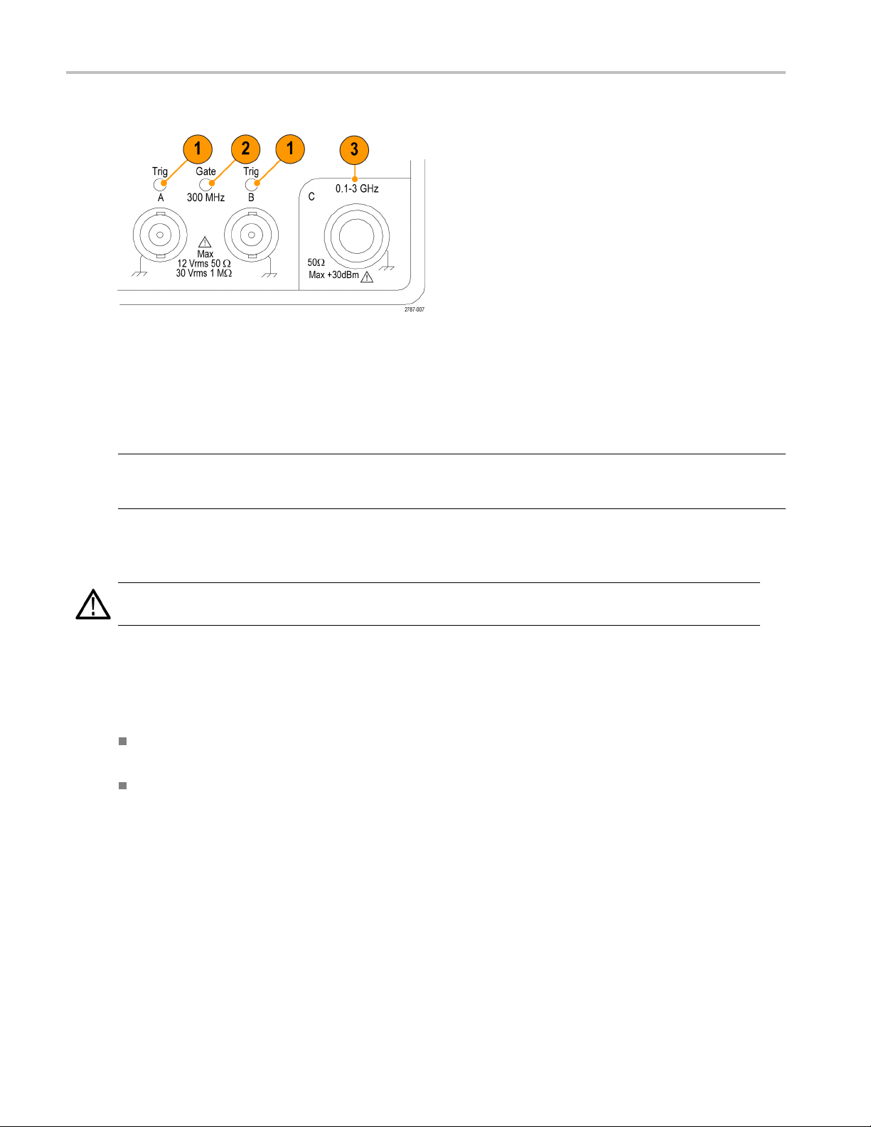
Input Connectors
1. Input A and Input B connectors, and input trigger indicators.
2. Gate indicator. The GATE indicator is on when the counter is busy counting input cycles.
3. Input C prescaler (3 GHz or 20 GHz, FCA3000 Series and FCA3100 Series) or down converter (27 GHz or 40 GHz,
MCA3000 Series) for measuring higher frequencies.
Getting Acquain
tedwithYourInstrument
NOTE. Ins
instruments only). The Gate and Trig A/B LED indicators remain on the front panel.
Prevent
CAUTION. A direct electrostatic discharge can damage the instrument input. To learn how to avoid this damage, read
the following information.
Electrostati
protection, however it is possible that large discharges of static electricity directly into the signal input may damage the
instrument. To avoid damage to the instrument, use the followi ng techniques to remove electrostatic charge from yourself
and test cabl
truments with Option RP have the input connectors on the rear panel (FCA3000 Series and FCA3100 Series
ing ESD
c discharge (ESD) is a concern when handling any electronic equipment. The instrument is designed with ES D
es before connecting any cables to the instrument:
Discharge th
disconnecting cables.
A cable that is left unconnected on a bench can develop a large static charge. Discharge the static voltage from all
cables before connecting them to the instrument or device under test by momentarily grounding the center conductor of
the cable, o
e static voltage from your body by wearing a grounded antistatic wrist strap while connecting and
r by connecting a 50 Ω termination to one end, before attaching the cable to the instrument.
FCA3000, FCA3100, and MCA 3000 Series Quick Start User Manual 5
Page 22

Getting Acquain
Controls
Power Button
Item Description
Measurement Buttons
Use the Measurement buttons to select and display a measurement.
Item Description
ted with Your Instrument
The Power button is a toggling secondary power switch. Part of the instrument is always on as soon as
line power is applied, indicated by the red LED above the button. Push the Power button to power on or
off the instrument.
Use the Meas button to display the instrument measurement menu along the bottom of the screen. Push a
menu button directly below a menu item to select that menu item and open a sub-menu as needed.
Typical measurements include frequency, period, time, pulse, phase, totalize (FCA3100 Series only), and
volts. The available menu items depend on the instrument model and configuration.
Use the Value button to display the current measurement as a numerical value. The instrument also displays
supplementary measurements along the lower part of the screen.
Use the Analyze button to display the current measurement in one of three statistical analysis display modes.
Repeate
Use the Auto Set button to automatically set trigger levels for the measurement function and input signal
amplitude (for relatively normal signals). This enables you to quickly set the instrument to display a
me
Push the Auto Set button twice within two seconds to re set most instrument settings (such as measuring
time, mathematics, filter and arming) to their default values. The intention is to prevent possible lockups and
mi
dly push the Analyze button to cycle through the statistical display modes:
cal display: The instrument displays statistical data as numerical data. The statistical data
Numeri
readouts include Mean (running mean value of the main measurement over N samples), Max ( maximum
value), Min (minimum value), P-P (peak-to-peak deviation), Adev (Allan deviation), and Std (standard
ion). (See page 10, Numerical display.)
deviat
Histogram display: The instrument displays successive main measurement results as a histogram. The
n the histogram are autoscaled based on the measured data. Limits, if active, and the running mean
bins i
value X are shown as vertical dotted lines. The center of the graph is indicated by a filled triangle on
the X-axis. The plot scale factor, plot center measurement value, and measurement percent complete
s are shown along the bottom of the plot. Limit se ttings affect the autoscaling to show the current
value
measurements and the set limits simultaneously. (See page 11, Histogram display.)
Use the Settings > Stat > No. Of Samples menu to set the number of bins along the horizontal axis.
Trend Plot display: The instrument displays successive main measurement results as a trend plot. This
mode is useful for observing periodic fluctuations or possible trends. The trend plot autoscales based
e measured data, starting with 0 at restart. Limits (if active) are shown as horizontal lines. (See
on th
page 11, Trend plot display.)
asurement.
sinterpretations when changing measurement function or test setup.
6 FCA3000, FCA3100, and MCA3000 Series Quick Start User Manual
Page 23

Getting Acquain
tedwithYourInstrument
Navigation Buttons
Use the Navigation buttons to select menu items, increment or decrement numeric setting values, and clear numeric values.
Item Description
The Navigation buttons provide multiple functions depending on the instrument mode:
Menu mode: Use the left-arrow, right-arrow, and Enter buttons to display and select menu items
(as an alternative to using the keypad menu select buttons).
Numeric entry mode: Use the left-arrow button to clear the right-most digit in a settings field. Use
the up- and down-arrow buttons to increment or decrement a numeric value in a settings field
(in a 1-2-5 pattern).
Use the Enter button to accept the displayed value or menu and return to the previous menu.
When the instrument is not displaying a menu or prompting for input, use the up- and down-arrow
buttons to set the LCD screen contrast.
Use the Save/Exit button to confirm the current selection and exit to the previous menu level.
Use the Esc button to exit to the previous menu level without confirming the current selection.
Keypad Buttons
Use the keypad buttons to select menu items and enter setting values.
Item Description
Numeric buttons Use buttons 1-0, ., and ± to enter numeric parameter values.
Menu select buttons
Menu access buttons
Use the top row of the keypad buttons (1-5 and the two blank buttons) to select the
corresponding screen menu items.
Use the bottom row of the keypad buttons (6-0) to display the menu for that button (Input A,
Input B, Settings, and so on).
Use the Input A or Input B buttons to display the input channel configuration menu for the
selected channel.
The Input A and Input B menus provide channel-related settings, including trigger slope, signal
coupling (AC or DC), input impedance (50 Ω or 1 MΩ), input attenuation (1x or 10x), trigger
mode (Manual or Auto), Trigger level, and Filter (frequency cutoff).
FCA3000, FCA3100, and MCA 3000 Series Quick Start User Manual 7
Page 24

Getting Acquain
Item Description
ted with Your Instrument
Use the Settings button to display the measurement settings configuration menu.
The Settings m
(for frequency measurements), Burst (for pulse-modulated signals), Arming ( conditional
measurement start/stop), Trigger Holdoff (stop trigger delay), Statistics (settings for statistical
measurements
Miscellaneous (such as the input signal timeout period and the auto trigger low frequency
setting).
See the FCA30
instrument menus and settings.
Use the M a th/L imit button to display the m ath and limit testing configuration menus.
The Math menu provides predefined formulas and user-defined constants to mathematically
postproce
measurement to take into account a mixer or multiplier that is part of the signal under test.
The Limits menu lets you set numerical limits and select how the instrument reports limit
violation
Use the Us
The User Options menu provides instrument settings, including saving or recalling instrument
setups (factory default or up to twenty user setups in nonvolatile memory, each with a unique
bus interface selection (USB or GPIB), GPIB bus con figuration (mode, address),
label),
instrument self-tests, conditional pulse output signal setup (FCA3100 Series only), and
instrument configuration information (model, serial number, firmware, and configuration).
The User
calibration process requires password access. See the FCA3000 and FCA3100 Series
Timer/Counter/Analyzers and MCA3000 Series Microwave Counter/Analyzers Technical
nce Manual for instructions on how to do an internal instrument calibration.
Refere
Use the
between run (constantly acquiring measurements) and hold (measurement pause) modes.
The measurement indicator in the upper right corner of the screen changes from MEAS to
HOLD w
again to resume the normal (continuous) m easurement mode.
While in the hold mode, you can push the Restart button to take single measurements. The
urement indicator in the upper right corner of the screen changes from HOLD to SING
meas
when the instrument is taking a single measurement.
he Restart button to zero the measurement values and retake a measurement. This
Use t
is useful when you need to initiate a new measurement after a change in the input signal,
especially when using long measuring times.
ake a single measurement, push Hold/Run to put the instrument in Hold mode (the
To t
measurement indicator changes from MEAS to HOLD), and then push the Restart button. The
measurement indicator changes from HOLD to SING, the instrument takes the measurement,
the indicator returns to HOLD.
and
Restart does not affect any instrument settings.
enu provides measurement-related settings, including Measure Time
including number of samples), Time base Reference (internal or external), and
00 Series and MCA3000 Series User Manual for full information on these
ss the measurement result. A typical use for math processing is to convert a
s.
er Opt button to display the user options configuration menu.
Options menu also provides an instrument calibration function. This internal
Hold/Run button to control measurement acquisition. Push the button to toggle
hen the instrument is in the measurement hold mode. Push the Hold/Run button
8 FCA3000, FCA3100, and MCA3000 Series Quick Start User Manual
Page 25

Main Screen
The instrument uses a monochrome LCD to show signal sources, instrument measurements (numerical and graphical), and
menu items. What items are shown depends on the display mode.
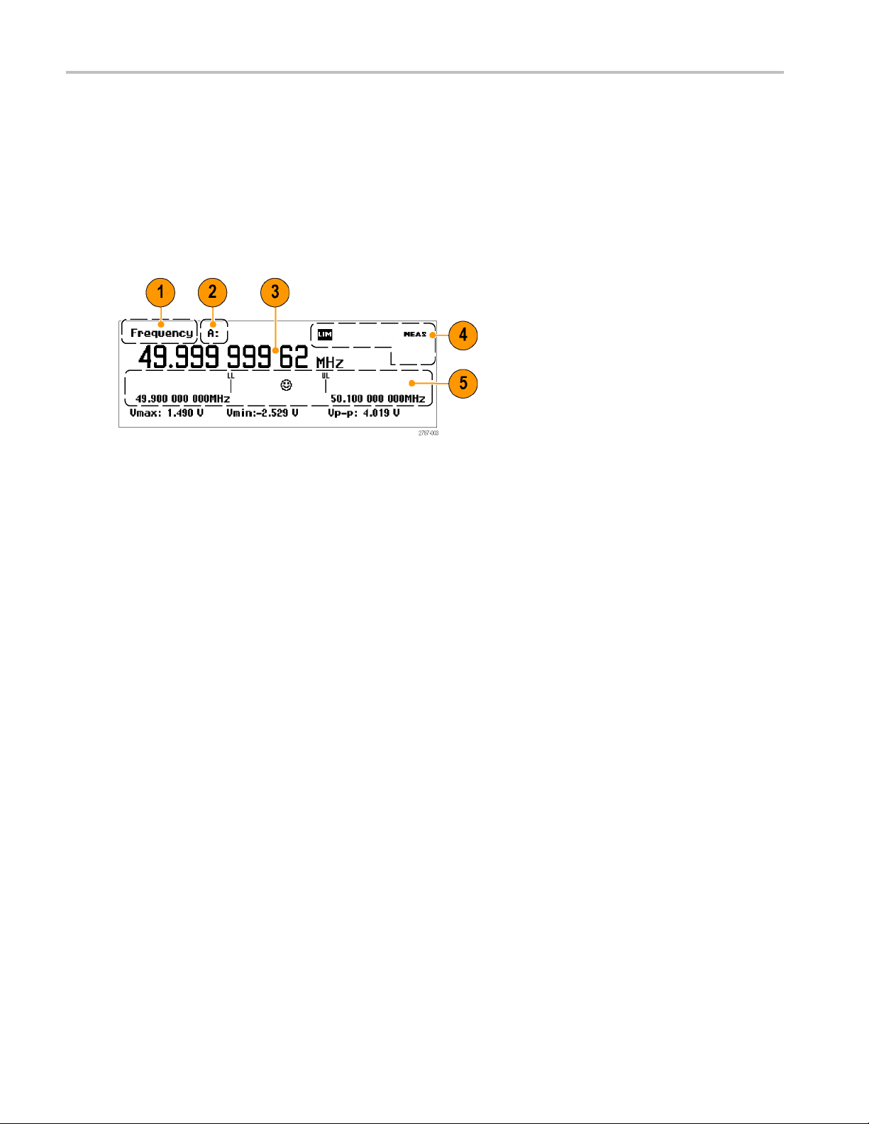
Measurement Value Mode
Getting Acquain
tedwithYourInstrument
Push the Val
1. The current measurement.
2. The measurement signal source.
3. The main measurement readout. The readout at the bottom of the screen shows electrical information for the source
signal. The readouts or display changes depending on the measurement or analysis mode.
4. Measurement status. Shows the math or limit testing mode (MATH or LIM), the measure status (MEAS, HOLD, or SING),
and if t
all display modes.
5. Limit Alarm readout (when active). Lower limit (LL) and upper limit (UL) settings are shown as vertical bars with their
associated limit value. An emoticon icon shows the relative measurement value and limit pa ss/fail state (a s m iling face
when t
status text at the top of the screen flashes when the measurement exceeds the limits, and continues to flashevenwhen
the measurement is back within limits. Push the Restart button to reset the LIM indicator.
ue button to enable this mode and show a high-resolution numeric readout of the current measurement.
he instrument is being remotely controlled from the GPIB bus (REM). The measurement status is present in
he measurement is within the limits, and a frowning face when the m easurement is outside the limits). The LIM
FCA3000, FCA3100, and MCA 3000 Series Quick Start User Manual 9
Page 26

Getting Acquain
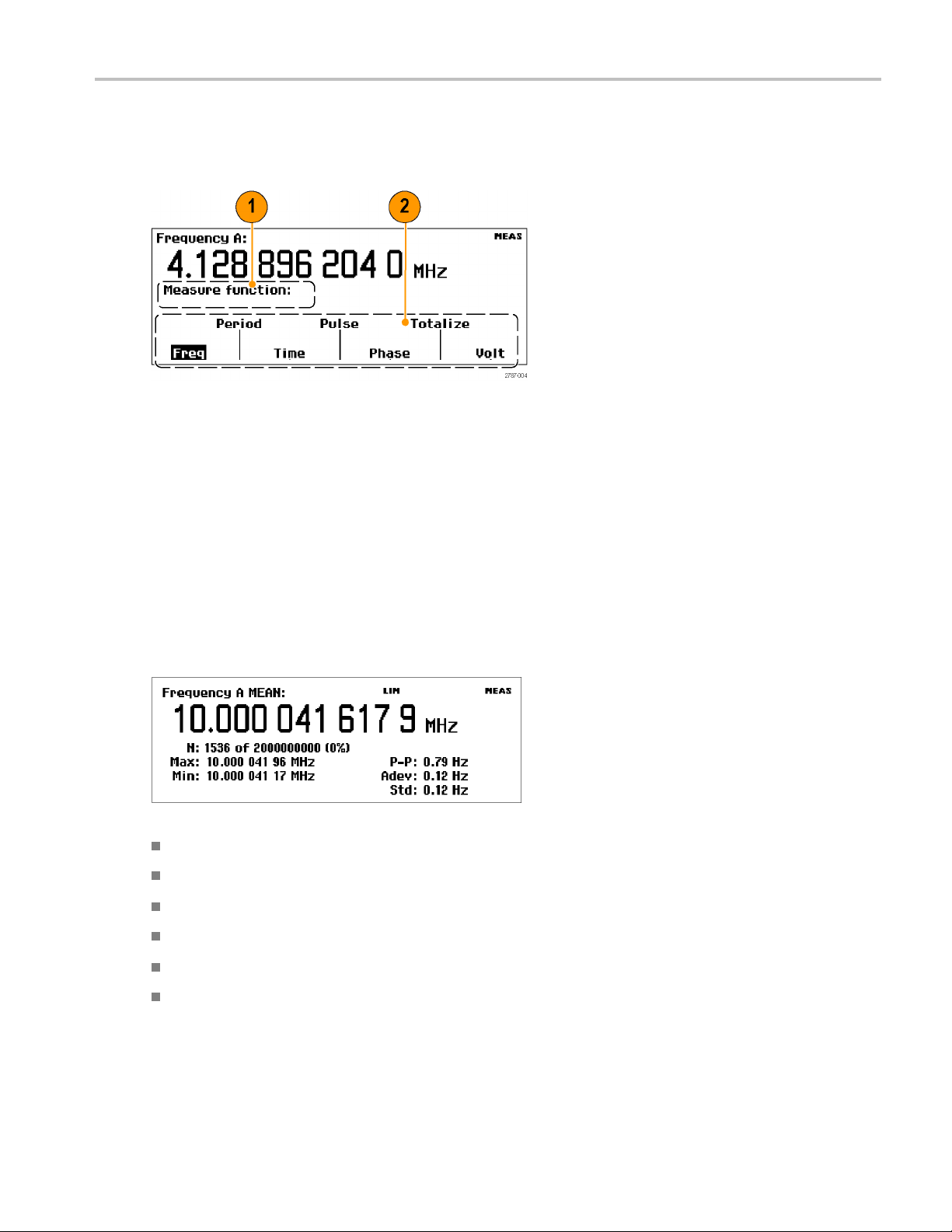
Menu Mode
Pushing a menu button (Meas, Input A, Input B, Settings, Math/Limit, or User Opt) replaces the lower screen area with the
menu items for that button. The following figure shows the menu items for the Meas button.
1. The Path area shows the menu path of the current menu selections.
2. The Menu area shows the available menu options. Push the keypad button directly below a menu item to select that
item and/or open a lower-level menu. The current selection is shown in inverse text. You can also use the Navigation
buttons to highlight and select menu items.
ted with Your Instrument
Analyze Modes
The Anal
to display numerical, histogram, or trend plot statistical analysis readouts.
Numerical display. The instrument takes successive measurements and displays the results as numeric statistical
readouts.
yze modes (accessible by repeatedly pushing the A nalyze button) apply basic statistical analysis to measurements
MEAN: The main measurement shows the running mean value over N samples.
N: The number of measurement samples (set in the Settings > Stat menu).
Max, Min: The maximum and minimum measurement values.
P-P: The peak-to-peak deviation.
Adev: Allan deviation.
Std: Standard deviation.
10 FCA3000, FCA3100, and MCA3000 Series Quick Start User Manual
Page 27

Getting Acquain
tedwithYourInstrument
Histogram display. The instrument displays successive measurements as a histogram. The number of bins along
the horizontal
1. The upper and lower Limits Alarm levels (if active). When limit testing is active, the instrument autoscales the graph to
show both the histogram and the limit. The instrument only uses data inside the limits for autoscaling; measurements
outside the visible graph area are shown by an arrowhead at the left or the right edge of the display.
axis are set in the Settings > Stat menu.
2. The running mean measurement value (X
3. The percent of the measurement completed.
4. The graph center (marked with a dark triangle) and corresponding frequency.
5. The graph horizontal scale per division. Limits Alarm (if active) sets the scale to s how both the current measurements
and the limit settings. The instrument continually autoscales the histogram bins based on the measured data.
).
Trend plot display. The instrument takes successive measurements and plots the values over time. This mode is useful
for observing fluctuations or measurement deviation trends. A trend plot stops (if Hold is activated) or restarts (if Run is
activated) after the set number of samples is completed. The trend plot graph continually autoscales based on the measured
data, starting with zero at restart. Limit Alarms, if active, are shown as horizontal lines.
1. The upper and lower frequency range of the plot display. The trend plot graph continually autoscales based on the
measured data to show the measurement trend values.
2. The percent of the measurement completed.
3. The horizontal units per division.
4. The Limits Alarm levels (if active). When limit testing is active, the instrument sets the graph scale to show both the
measurement trend plot and the limit values (horizontal dashed lines).
FCA3000, FCA3100, and MCA 3000 Series Quick Start User Manual 11
Page 28

Application Exa
mples
Application Examples
Assumptions for the examples in this section unless noted otherwise; 1 MHz signal, 5 Vpp square wave source connected to
the instrument using 50 Ω cables; input signals levels and frequency are within acceptable range.
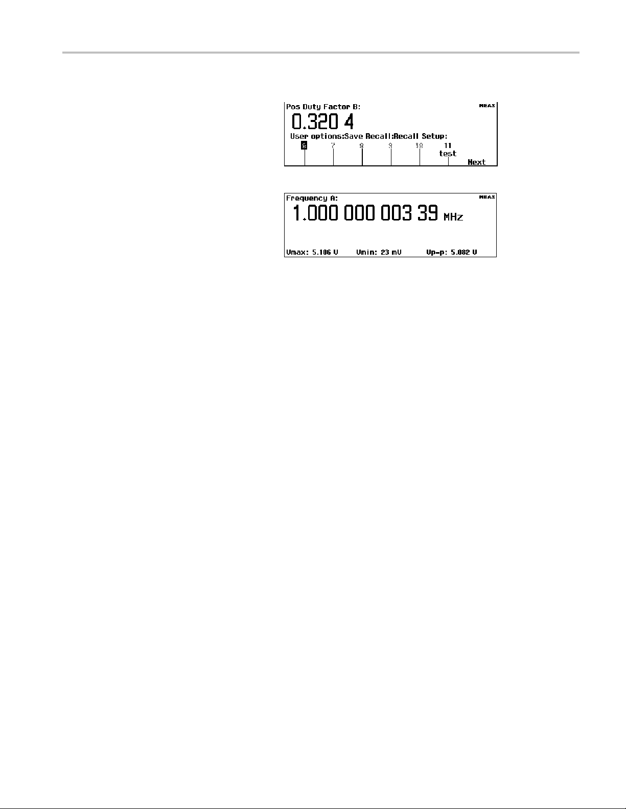
Restore Default Settings
1. Push User Opt > Save/Recall > Setup >
Recall Setup > Default to recall (load)
the instrument default setup. The
instrument displays the Frequency
measurement by default.
Basic Measurements
Prerequisite: Reset the instrument to the default settings. (See page 12, Restore Default Settings.)
1. Push Meas to open the Measurement
menu.
2. Select a measurement by using the
menu softkeys below a menu item.
mple, select Period > Single > A
For exa
to display the period measurement for
Input A.
>
12 FCA3000, FCA3100, and MCA3000 Series Quick Start User Manual
Page 29

Math Measurement
The built-in math functions let you apply postprocessing operations, such as scaling and offsetting to the measurement.
One use for this is to display the deviation from a desired value. This is known as offsetting. The value X in the formulas
represents the instrument measurement value.
Prerequisite: Reset the instrument to the default settings. (See page 12, Restore Default Settings.)
1. Push Math/Limit to open the Math a nd
Limits menu.
2. Select Math > Math Off > (K*X+L)/M.
3. Select L and enter –1 EE6.
Application Exa
>
mples
4. Repeatedly push Save/Exit to exit
the men
measurement readout. T he instrument
displays the deviation frequency from
1MHz(
Limit Testing
This example tests frequency limits, but you can set test limits for most measurements.
1. Reset the instrument to the default
ings. (See page 12, Restore Default
sett
Settings.)
2. Push Math/Limit and select Limits.
u levels and return to the
in this case, 29.91 milliHertz).
>
FCA3000, FCA3100, and MCA 3000 Series Quick Start User Manual 13
Page 30

Application Exa
3. Push Limit Behavior Off and select
4. Verify that the Limit Mode is set to
5. Select Lower Limit and enter the lower
mples
Alarm_Stop. The instrument returns to
the previous m
Behavior menu label to Alarm_Stop.
Range.
measureme
Save/Exit to accept the value.
Repeat this step to set the Upper L imit
value.
enu and changes the Limit
nt limit value. Push Enter or
6. Repeatedly push Save/Exit to ex it
the menu system and return to the
measurement display. Then push
Restart.
The range mode limit test readout uses
vertical lines to represent the lower and
upper limit values, and an emoticon
(smiley face) to indicate when the
measurement is within or outside the
limits.
Measurements that are outside the
displayed limits are shown with a
frowning emoticon and a flashing LIM
status indicator.
Measurements that are outside the limit
testscaleareshownwithanarrowatthe
left or the right edge of the screen. The
instrument only uses data that is inside
the limits for autoscaling.
14 FCA3000, FCA3100, and MCA3000 Series Quick Start User Manual
Page 31

Application Exa
mples
7. You can also dis
as part of other readouts. For example,
push the Analyze button repeatedly until
the instrumen
readout.
8. To stop (disable) limit testing, push
Math/Limit > Limit Behavior > Off.
play the limit settings
t shows the Histogram
Two-Channel Measurements
Prerequisite: Reset the instrument to the default settings. (See page 12, Restore Default Settings.)
1. Push the Input A and Input B
buttons and verify that the settings
are approp
The input settings are identical for this
example.
2. Connect signals to inputs A and B.
3. Push Meas and select Phase > B Rel
A. The instrument displays the B input
phase di
riate for your measurement.
fference relative to the A input.
4. Push Meas and select Time > Time
Interval > A to B. The instrument
displays the time interval from the rising
edge of Input A to the rising edge of
Input B.
t C Measurements
Inpu
Instruments that include the Input C high-frequency prescaler (FCA3000 Series, FCA3100 Series) or down converter
(MCA3000 Series) provide a subset of measurements for the C input. These measurements are Frequency, Frequency Ratio
(C to A and C to B), Frequency Burst, and Period (Average). Input C is added to the relevant menus on the instrument.
Use normal processes to set the instrument to take measurements on Input C. See the FCA3000 Series, FCA3100 Series,
and MCA3000 Series User Manual for m ore information on Input C measurements.
FCA3000, FCA3100, and MCA 3000 Series Quick Start User Manual 15
Page 32

Application Exa
mples
Save an Instrument Setup
The instrument provides 20 nonvolatile m emory locations in which to store instrument setup information. All instrument
parameters are stored including measurement settings, trigger levels, mathematical constants, and so on. You can label
each stored setup with a unique identifier (up to seven characters long).
NOTE. Restoring the default instrument setup does not erase the setups stored in memory.
1. Set the instrument to the configuration
that you want to save.
2. Push User Opt > Save/Recall > Setup >
Save Current Setup.
3. Select Next until the instrument displays
an available location (indicated by a
nt number). Locations that are
black fo
empty or unavailable are shown in gray
text.
4. Push the menu key to select a location
.
number
NOTE.
protected by default to prevent accidental
overwriting of their contents. See the User
manua
protection.
5. Use t
6. Use the Navigation buttons to backspace
7. Push Enter or Save/Exit to accept the
Setup locations 1 through 10 are
l for information on setup location
he menu softkeys to enter a label
(up to seven characters long) for the
instrument setup file. The default label is
ived from the current measurement.
der
er characters or move the insertion
ov
cursor to a new position.
label text and save the instrument setup.
16 FCA3000, FCA3100, and MCA3000 Series Quick Start User Manual
Page 33
Recall a Setup
Application Exa
mples
1. Push User Opt >
Recall Setup.
2. Push the Next menu button to display
the location from which to recall the
instrument s
empty are shown in gray text.
3. Push the menu button for the setup
location. The instrument loads the
setup and di
associated with that setup.
Save/Recall > Setup >
etup. Locations that are
splays the measurement
FCA3000, FCA3100, and MCA 3000 Series Quick Start User Manual 17
Page 34

Connectivity
Connectivity
With the fast USB and GPIB bus transfer speeds of your FCA3000, FCA3100, and MCA3000 Series bench instrument, you
can easily capture, save, and analyze measurement results by using the special Tektronix edition of National Instruments
LabVIEW SignalExpress™ software. Every instrument ships with a free copy of the Tektronix version of SignalExpress for
basic instrument control, data logging and analysis. An optional Full Edition offers over 200 built-in functions that provide
additional signal processing, advanced analysis, sweeping, limit testing and user-defined step capabilities.
SignalExpress connects the entire range of Tektronix bench instruments to let you access the feature-rich tools of each
instrument from one intuitive software interface. A single interface lets you automate complex measurements requiring
multiple instruments, time correlate data from multiple instruments, log data for an extended period of time, and easily
capture and analyze your results, all from your PC.
An optional TimeView™ Modulation Domain Analysis PC software application (TVA3000) allows for instrument remote
control and the analysis and display of measurement results in a choice of graphs. You can analyze practically any type of
dynamic variation of time or frequency, including modulation, jitter, wander, sweep linearity, frequency agile communication,
wireless LANs, Bluetooth frequency hopping, VCO frequency response and much more. For example, you can display
results as raw data, as a statistical histogram, as a waveform graph (as if you were using an oscilloscope), or as an FFT
spectrum graph. TimeView also lets you analyze modulation parameters such as modulation depth or frequency modulation
index. You can download a 30-day trial version of TimeView from the Tektronix Web site (www.tektronix.com).
18 FCA3000, FCA3100, and MCA3000 Series Quick Start User Manual
Page 35

x
FCA3000 および FCA3100 シリーズ・タイマ/カウン
タ/アナライザ
MCA3000 シリーズ・マイクロ波カウンタ/アナライザ
ZZZ
クイック・スタート・ユーザ・マニュアル
*P071278801*
071-2788-01
Page 36

Page 37

xx
FCA3000 および FCA3100 シリーズ・タイマ/カウンタ
/アナライザ
MCA3000 シリーズ・マイクロ波カウンタ/アナライザ
ZZZ
クイック・スタート・ユーザ・マニュアル
www.tektronix.com
071-2788-01
Page 38

Copyright © Tektronix. All rights reserved. 使用許諾ソフトウェア製品は、Tektronix またはその子会社や供給者が
所有するもので、米国著作権
法および国際条約の規定によって保護されています。
Tektronix 製品は
発行されている他の資料の内容に代わるものです。 また、本製品の仕様および価格は、予告なく変更させていただ
く場合がございますので、予めご了承ください。
TEKTRONIX および TEK は Tektronix, Inc. の登録商標です。
LabVIEW、National Instruments、NI、および SignalExpress は National Instruments の商標です。
TimeView は Pendulum Instruments AB の商標です。
Tektronix 連
Tektronix, Inc.
14150 SW Karl Braun Drive
P.O. Box 500
Beaverton, OR 97077
USA
製品情報、代理店、サービス、およびテクニカル・サポート:
北米内:1-800-833-9200 までお電話ください。
世界の他の地域では、www.tektronix.com にアクセスし、お近くの代理店をお探しください。
、登録済および出願中の米国その他の国の特許等により保護されています。 本書の内容は、既に
絡先
Page 39

保証
当社では、本製品において、出荷の日から 3 年間、材料およびその仕上がりについて欠陥がないことを保証します。
この保証期間中に製品に欠陥があることが判明した場合、当社では、当社の裁量に基づき、部品および作業の費
用を請求せずに当該欠陥製品を修理するか、あるいは当該欠陥製品の交換品を提供します。保証時に当社が使用
する部品、モジュール、および交換する製品は、新しいパフォーマンスに適応するために、新品の場合、または再生
品の場合もあります。交換したすべての部品、モジュール、および製品は当社で保有されます。
本保証に基づきサービスをお受けいただくため、お客様には、本保証期間の満了前に当該欠陥を当社に通知して
いただき、サービス実施のための適切な措置を講じていただきます。お客様には、当該欠陥製品を梱包していただ
き、送料前払いにて当社指定のサービス・センターに送付していただきます。本製品がお客様に返送される場合に
おいて、返送先が当該サービス・センターの設置されている国内の場所であるときは、当社は、返送費用を負担し
ます。しかし、他の場所に返送される製品については、すべての送料、関税、税金その他の費用をお客様に負担し
ていただきます。
本保証は、不適切な使用または不適切もしくは不十分な保守および取り扱いにより生じたいかなる欠陥、故障または
損傷にも適用されません。当社は、以下の事項については、本保証に基づきサービスを提供する義務を負いません。
a)当社担当者以外の者による本製品のインストール、修理またはサービスの試行から生じた損傷に対する修理。b)不
適切な使用または互換性のない機器への接続から生じた損傷に対する修理。c)当社製ではないサプライ用品の使用
により生じた損傷または機能不全に対する修理。d)本製品が改造または他の製品と統合された場合において、改造
または統合の影響により当該本製品のサービスの時間または難度が増加したときの当該本製品に対するサービス。
この保証は、明示的または黙示的な他のあらゆる保証の代わりに、製品に関して当社がお客様に対して提供するも
のです。当社およびベンダは、商品性または特定目的に対する適合性についての一切の黙示保証を否認します。
欠陥製品を修理または交換する当社の責任は、本保証の不履行についてお客様に提供される唯一の排他的な法
的救済となります。間接損害、特別損害、付随的損害または派生損害については、当社およびそのベンダは、損害
の実現性を事前に通知されていたか否に拘わらず、一切の責任を負いません。
[W4 – 15AUG04]
Page 40

Page 41

目次
安全にご使用いただくために.......................................................................... iii
適合性に関する情報.................................................................................. v
はじめに............................................................................................. viii
インストレーション............................................................................................ 1
機器の概要........................................................................................... 4
使用例 .............................................................................................. 14
接続................................................................................................. 20
目次
EMC...................................................................................................... v
安全性 ........................................................................................... vi
環境に関する考慮事項 .......................................................................... vii
主な特長 ........................................................................................ viii
マニュアル ....................................................................................... ix
このマニュアルで使用
機器の開梱 ...................................................................................... 1
動作要件......................................................................................... 2
機器の電源投入と切断 ........................................................................... 2
機能チェック...................................................................................... 3
フロント・パネル................................................................................... 4
リア・パネル....................................................................................... 5
入力コネクタ...................................................................................... 6
コントロール ...................................................................................... 7
メイン画面....................................................................................... 10
デフォルト設定のリストア ......................................................................... 14
基本的な測定 ................................................................................... 14
演算測定........................................................................................ 15
リミット・テスト .................................................................................... 15
2 チャンネルの測定.............................................................................. 17
C の測定 .................................................................................. 17
Input
機器の設定値の保存 ............................................................................ 18
される表記規則 ............................................................. ix
FCA3000、FCA3100、および MCA3000 シリーズ・クイック・スタート・ユーザ・マニュアル i
Page 42

目次
ii FCA3000、FCA3100、および MCA3000 シリーズ・クイック・スタート・ユーザ・マニュアル
Page 43

安全にご使用いただくために
人体への損傷を避け、本製品や本製品に接続されている製品への損傷を防止するために、次の安全性に
関する注意をよくお読みください。
安全にご使用いただくために、本製品の指示に従ってください。
資格のあるサービス担当者以外は、保守点検手順を実行しないでください。
本製品をご使用の際に、規模の大きなシステムの他の製品にアクセスしなければならない場合があります。
システムの操作に関する警告や注意事項については、他製品のマニュアルにある安全に関するセクション
をお読みください。
火災や人体への損傷を避けるには
適切な電源コードを使用してください。 本製品用に指定され、使用される国で認定された電源コードの
みを使用してくださ
い。
安全にご使用いただくために
接続と切断は正しく
ないでください。
行ってください。
プローブと検査リードは、電圧ソースに接続されている間は着脱し
本製品を接地してください。 本製品は、電源コードのグランド線を使用して接地します。 感電を避けるた
め、グランド線をアースに接続する必要があります。 本製品の入出力端子に接続する前に、製品が正しく接
地されていること
すべての端子の
マーキングに従ってください。 本製品に電源を接続する前に、定格の詳細について、製品マニュアルを参
照してください。
本製品の定格は測定カテゴリIになります。一次回路、設置カテゴリII,III,およびIVの回路には接続しな
いでください
共通端子を含
電源を切断し
ないでください。このコードは常にアクセス可能であることが必要です。
を確認してください。
定格に従ってください。
。
むどの端子にも、その端子の最大定格を超える電位をかけないでください。
てください。
電源コードの取り外しによって主電源が切り離されます。電源コードをさえぎら
火災や感電の危険を避けるために、本製品のすべての定格と
カバーを外した状態で動作させないでください。 カバーやパネルを外した状態で本製品を動作させな
いでください。
故障の疑いがあるときは動作させないでください。 本製品に故障の疑いがある場合、資格のあるサー
ビス担当者
露出した
触れないでください。
に検査してもらってください。
回路への接触は避けてください。
電源がオンのときに、露出した接続部分やコンポーネントに
湿気の多いところでは動作させないでください。
爆発性のあるガスがある場所では使用しないでください。
製品の表面を清潔で乾燥した状態に保ってください。
適切に通気してください。
の設置方法を参照してください。
FCA3000、FCA3100、および MCA3000 シリーズ・クイック・スタート・ユーザ・マニュアル iii
適切な通気が得られるような製品の設置方法の詳細については、マニュアル
Page 44
安全にご使用いただくために
本マニュアル内の用語
本マニュアルでは、次の用語を使用します。
警告: 人体や生命に危害をおよぼすおそれのある状態や行為を示します。
注意: 本製品やその他の接続機器に損害を与える状態や行為を示します。
本製品に関する記号と用語
本製品では、次の用語を使用します。
DANGER: ただちに人体や生命に危険をおよ
WARNING: 人体や生命に危険をおよぼす可
CAUTION: 本製品を含む周辺機器に損傷
本製品では、次の記号を使用します。
ぼす可能性があることを示します。
能性があることを示します。
を与える可能性があることを示します。
iv FCA3000、FCA3100、および MCA3000 シリーズ・クイック・スタート・ユーザ・マニュアル
Page 45

適合性に関する情報
このセクションでは、本製品が適合している EMC 基準、安全基準、および環境基準について説明します。
EMC
EC 適合宣言 - EMC
指令 2004/108/EC 電磁環境両立性に適合します。『Official Journal of the European Communities』に記載
の以下の基準に準拠します。
適合性に関する情報
EN 61326-1:2006、EN 61326-2-1:2006: 測定、制御、および実験用途の電子機器を対象とする EMC
基準。
123
CISPR 11:2003:グループ 1、クラス A、放射および伝導エミッション
IEC 61000-4-2:2001:静電気放電イミュニティ
IEC 61000-4-3:2002:RF 電磁界イミュニティ
4
IEC 61000-4-4:2004:電気的ファスト・トランジェント/バースト・イミュニティ
IEC 61000-4-5:2001:電源サージ・イミュニティ
IEC 61000-4-6:2003:伝導 RF イミュニティ
IEC 61000-4-11:2004:電圧低下と停電イミュニティ
4
5
EN 61000-3-2:2006: AC 電源ライン高調波エミッション
EN 61000-3-3:1995: 電圧の変化、変動、およびフリッカ
欧州域内連絡先:
Tektronix UK, Ltd.
Western Peninsula
Western Road
Bracknell, RG12 1RF
1
本製品は住居区域以外での使用を目的としたものです。住居区域で使用すると、電磁干渉の原因となることがあります。
2
本製品をテスト対象に接続した状態では、この規格が要求するレベルを超えるエミッションが発生する可能性があります。
3
ここに挙
4
信号を A
±1 Hz まで変化することがあります。
5
70%/
げた各種 EMC 規格に確実に準拠するには、高品質なシールドを持つインタフェース・ケーブルが必要です。
機器に IEC 61000-4-3 および IEC 61000-4-6 の各試験で定義する電磁界と信号をかけ、10 MHz、0.1 Vp-p の正弦波
または B 入力チャンネルに印加した場合、機器の周波数リードアウト値は固有基本変動に超えて標準で最大
25 サイクルの電圧低下および 0%/250 サイクルの瞬断テスト・レベルにおいて、性能基準 C を適用(IEC 61000-4-11)。
FCA3000、FCA3100、および MCA3000 シリーズ・クイック・スタート・ユーザ・マニュアル v
Page 46

適合性に関する情報
オーストラリア/ニュージーランド適合宣言 - EMC
ACMA に従い、次の規格に準拠することで Radiocommunications Act の EMC 条項に適合しています。
CISPR 11:2003:グループ 1、クラス A、放射および伝導エミッション(EN61326-1:2006 および EN613262-1:2006 に準拠)
オーストラリア/ニュージーランドの連絡先:
Baker & McKenzie
Level 27, AMP Centre
50 Bridge St
Sydney NSW 2000, Australia
安全性
EC 適合宣言 - 低電圧指令
『Official Journal of the European Communities』に記載の以下の基準に準拠します。低電圧指令 2006/95/EC
IEC 61010-1: 2001: 測定、制御および実験用途の電子装置に対する安全基準
reet
米国の国家認定
UL 61010-1:2004 年第 2 版。電子計測器および試験用機器の標準規格
試験機関のリスト
カナダ認証
CAN/CS
1部
A-C22.2 No.61010-1:2004:測定、制御、および実験用途の電子装置に対する安全基準、 第
その他の基準に対する適合性
IEC 61010-1:2001:測定、制御、および実験用途の電子装置に対する安全基準
機器の種類
測定機器
クラス
安全
クラス 1:アース付き製品
vi FCA3000、FCA3100、および MCA3000 シリーズ・クイック・スタート・ユーザ・マニュアル
Page 47
適合性に関する情報
汚染度
製品内部およびその周辺で発生する可能性がある汚染度の尺度です。通常、製品の内部環境は外部環境
と同じとみなされます。製品は、その製品に指定されている環境でのみ使用してください。
汚染度 1:汚染なし、または乾燥した非導電性の汚染のみが発生します。このカテゴリの製品は、通常、
被包性、密封性のあるものか、クリーン・ルームでの使用を想定したものです。
汚染度 2:通常、乾燥した非導電性の汚染のみが発生します。ただし、結露によって一時的な導電性が
発生することもまれにあります。これは、標準的なオフィスや家庭内の環境に相当します。一時的な結露
は製品非動作時のみ発生します。
汚染度 3:伝導性のある汚染、または通常は乾燥して導電性を持たないが結露時に伝導性を帯びる汚
染。これは、温度、湿度のいずれも管理されていない屋内環境に相当します。日光や雨、風に対する直
接の曝露からは保護されている領域です。
汚染度 4:導電性のある塵、雨、または雪により持続的な導電性が生じる汚染。これは一般的な屋外環
境に相当します。
汚染度
汚染度 2(IEC
61010-1 の定義による)。注:屋内使用のみについての評価です。
環境に関する考慮事項
このセクションでは本製品が環境におよぼす影響について説明します。
使用済み製品の処理方法
機器またはコンポーネントをリサイクルする際には、次のガイドラインを順守してください。
機器のリサイクル: この機器を生産する際には、天然資源が使用されています。本製品には環境または
人体に有害となる可能性のある物質が含まれているため、廃棄の際には適切に処理する必要があります。
有害物質の放出を防ぎ、天然資源の使用を減らすため、本製品の部材の再利用とリサイクルの徹底にご協
力ください。
この記号は、本製品が WEEE(廃棄電気・電子機器)およびバッテリに関する Directive
2002/96/EC および 2006/66/EC に基づき、EU の諸要件に準拠していることを示しています。
リサイクル方法については、当社 Web サイト(www.tektronix.com)の「Service and Support」のセ
クションを参照してください。
有害物質に関する規制
本製品は Monitoring and Control(監視および制御)装置に分類され、2002/95/EC RoHS Directive(電気・
電子機器含有特定危険物質使用制限指令)の適用外です。
FCA3000、FCA3100、および MCA3000 シリーズ・クイック・スタート・ユーザ・マニュアル vii
Page 48

はじめに
はじめに
本マニュアルでは、FCA3000 シリーズ、FCA3100 シリーズ、および MCA3000 シリーズの機器のインストー
ルおよび基本的な操作について説明します。詳細については、FCA3000 シリーズ、FCA3100 シリーズ、お
よび MCA3000 シリーズ・ユーザ・マニュアル(製品 CD 内の PDF ファイルとして提供されます)を参照してく
ださい。このマニュアルは次の機器を対象にしています。
FCA3000 シリーズ:FCA3000 型、FCA3003 型、FCA3020 型
FCA3100 シリーズ:FCA3100 型、FCA3103 型、FCA3120 型
MCA3000 シリーズ:MCA3027 型、MCA3040 型
主な特長
40 GHz までの幅広い測定周波数レンジ
業界最高速のマイクロ波カウンタ(25 ms のアクイジション・タイム)
業界唯一のグラフィカル・ディスプレイ付き周波数カウンタ
50 ps シングル・ショット(時間)、または 12 桁/s(周波数)までの高い解像度
信号の周波数と電圧パラメータの同時表示
DC ~ 200 MHz で 15 mVrms のトリガ感度
1 mV までの電圧解像度
高速 USB/GPIB バス転送速度、最大で毎秒 15k の測定(ブロック・モード)
ゼロ・デッド・タイムの周波数/周期測定
最上位の OCXO(恒温槽型水晶発振器)タイム・ベース・オプション(1.5 E-8/年)
MAC3000 シリーズはマイクロ波 CW 周波数測定、および 40 ns までの極短バースト測定が可能
0.5 Hz ~ 50 MHz のプログラマブル・パルス出力(FCA3100 シリーズ)
10 MHz リファレンス出力オシレータ
測定値統計モード
ヒストグラム・モード
トレンド・プロット・モード
フロントまたはリアの入力接続オプション
viii FCA3000、FCA3100、および MCA3000 シリーズ・クイック・スタート・ユーザ・マニュアル
Page 49

マニュアル
本製品に関する各種マニュアルの参照先は次のとおりです。
参照項目 参照するマニュアル
インストレーション、操作概要
操作方法の詳細とユーザ・インタフェー
スに関するヘルプ
プログラマ・コマンド
解析、接続ツール
クイック・スタート・ユーザ・マニュアル:操作情報の概要を提供し
ます。
ユーザ・マニュアル(ドキュメンテーション・ブラウザ・ディスクに搭
載):機器の機能を使用するための詳細な指示を提供します。
プログラマ・マニュアル(ドキュメンテーション・ブラウザ・ディスク
に搭載):GPIB のコマンド構文が含まれています。
National Instruments の SignalView Express CD および Connectivity Installation Instructions(ドキュメンテーション・ブラウザ・ディ
スクに搭載)
このマニュアルで使用される表記規則
はじめに
このマニュアル
手順
連続したボタン操作は > 記号で区切られています。例えば、Meas>Pulse>WidthPositive>Aは、Meas ボ
タン、Pulse メニュー・ボタン、Width Positive メニュー・ボタン、そして A メニュー・ボタンを押すことを意味し
ます。
では次のアイコンを使用しています。
フロント・パ
ネル電源
電源の接続
USB
FCA3000、FCA3100、および MCA3000 シリーズ・クイック・スタート・ユーザ・マニュアル ix
Page 50

はじめに
x FCA3000、FCA3100、および MCA3000 シリーズ・クイック・スタート・ユーザ・マニュアル
Page 51

インストレーション
機器の開梱
機器を開梱し、スタンダード・アクセサリとして記載されているすべての付属品が含まれていることを確認し
ます。最新の情報、推奨アクセサリ、機器のオプション、およびアップグレードについては、当社 Web サイト
(www.tektronix.com)を参照してくだ さい。
スタンダード・アクセサリ
アクセサリ 当社部品番号
FCA3000 および FCA3100 シリーズ・タイマ/カウンタ/アナライザ、MCA3000 シリー
ズ・マイクロ波カウンタ/アナライザ・クイック・スタート・ユーザ・マニュアル(英語版/
簡体中国語版/日本語版)
製品マニュアル CD-ROM
NI LabVIEW SignalExpress CD-ROM
電源コード
N オス-BNC アダプタ(FCA3003 型、FCA3020 型、FCA3103 型および FCA3120 型
のみ)
校正証明書
インストレーション
071-2787-xx
063-4288-xx
063-4253-xx
各国固有
なし
なし
FCA3000、FCA3100、および MCA3000 シリーズ・クイック・スタート・ユーザ・マニュアル 1
Page 52

インストレーション
動作要件
機器を使用する場所が、以下の動作要件を満たしていることを確認してください。
要件 説明
周囲のスペース
AC 電源
温度 動作時: 0℃ ~ +50℃(32゚F ~ 122゚F)
湿度 +10℃ ~ +30℃(50゚F ~ 86゚F):5% ~ 95%
高度(最大)
非破壊最大入力電圧、入力 A
および入力 B
非破壊最大入力レベル、入力
C
上部および底部: 0 mm(0 インチ)
左側および右側: 51 mm(2 インチ)
リア:51mm(2インチ)
100 - 240 VAC ±10%、CAT II:50 - 400 Hz ±10%:40 W
非動作時: -40℃ ~ +71℃(-40゚F ~ +160゚F)
+30℃ ~ +40℃(86゚F ~ 104゚F):5% ~ 75%
+40℃ ~ +50℃(104゚F ~ 122゚F):5% ~ 45%
2,000 m(6,500 フィー ト)
50 Ω: 12 V
、デューティ・ファクタ 0.1% 未満で 35 V
rms
peak
、
1 MΩ、1X アッテネータ:440 Hz までは 350 V(DC + AC pk)、1 MHz で
は12V
まで低下
rms
1 MΩ、10X アッテネータ:440 Hz までは 350 V(DC + AC pk)、1 MHz で
は12V
FCA3003 型、FCA3103 型: 12 V
FCA3020 型、FCA3120 型:+27 dBm(5 V
MCA3027 型、MCA3040 型: +27 dBm(5 V
まで低下
rms
(+34 dBm)
rms
rms
rms
)
)
機器の電源投入と切断
本製品は、
操作のために、電源コードの接地線を通じた保護用グランド接続が不可欠です。
アース近辺に中性線を使用した単相電源で動作します。(2 ページ 「動作要件」 参照)。安全な
2 FCA3000、FCA3100、および MCA3000 シリーズ・クイック・スタート・ユーザ・マニュアル
Page 53

機能チェック
1. 機器の電源を投入します。
2. User Opt > Test の順に押します。
3. Test Mode メニュー・ボタンを押して、All を選択します。
4. Start test メニュー・ボタンを押します。すべてのテストに合格することを確認します。
5. OK メニュー・ボタンを押して、前の測定画面に戻ります。
6. リア・パネルの 10 MHz Output コネクタから、フロント・パネルの Input A コネクタに 50 Ω のケーブルを
接続します。
7. Input A を押して、50 Ω の入力インピーダンスを選択します。
8. Meas>Freq>Freq>Aの順に押します。機器が 10 MHz を示します。
インストレーション
FCA3000、FCA3100、および MCA3000 シリーズ・クイック・スタート・ユーザ・マニュアル 3
Page 54

機器の概要
機器の概要
フロント・パネル
1. 電源ボタン(7 ページ 「電源ボタン」 参照)。
2. メイン画面(10 ページ 「メイン画面」 参照)。
3. 測定ボタン(7 ページ 「測定ボタン」 参照)。
4. ナビゲーション・ボタン(8 ページ 「ナビゲーション・ボタン」 参照)。
5. 入力コネクタ(6 ページ 「入力コネクタ」 参照)。
6. キーパッド・ボタン(8 ページ 「キーパッド・ボタン」 参照)。
4 FCA3000、FCA3100、および MCA3000 シリーズ・クイック・スタート・ユーザ・マニュアル
Page 55

リア・パネル
機器の概要
1. パルス出力コネクタ(FCA3100 シリーズのみ) (6 ページ 「ESD の防止」 参照)。
2. 型番、シリアル番号、インストール・オプション、および機器の電気定格を記載した ID ラベル
3. AC 電源コネクタ
4. PC 接続用の USB 2.0 12 Mbps ポート
5. コントローラ接続用の GPIB ポート
6. オプションの入力コネクタ(フロント・パネルの入力コネクタ類をリア・パネルに移動する工場出荷時オプ
ション)。MCA3000 シリーズの機器では使用できません。 (6 ページ 「ESD の防止」 参照)。
7. 外部アーム入力コネクタ(測定の外部アーミング用(同期))。Settings メニューで、メイン入力 A および B
も測定アーミ
8. 外部リファ
信号が入力されている場合、この入力が自動的に選択されます)。 (6 ページ 「ESD の防止」 参照)。
9. 10 MHz 出力コネクタ。アクティブな測定リファレンス(内部または外部リファレンス)からのリファレンス信
号を出力します。測定リファレンスは Setteings メニューで設定します。 (6 ページ 「ESD の防止」 参照)。
ングに選択できます。 (6 ページ 「ESD の防止」 参照)。
レンス入力コネクタ(Settings メニューで Measurement Reference が Auto に設定され、有効な
FCA3000、FCA3100、および MCA3000 シリーズ・クイック・スタート・ユーザ・マニュアル 5
Page 56
機器の概要
入力コネクタ
1. 入力 A および入力 B コネクタ、および入力トリガ・インジケータ。
2. ゲート・インジケータ。ゲート・インジケータは、カウンタの入力サイクルのカウント中に点灯します。
3. 入力 C プリスケーラ(3 GHz または 20 GHz、FCA3000 シリーズおよび FCA3100 シリーズ)または、高周
波測定用ダウン・コンバータ(27 GHz または 40 GHz、MCA3000 シリーズ)
注: 機器にオプシ
よび FCA3100 シリーズの機器のみ)。ゲートおよび Trig A/B の LED インジケータは、フロント・パネルに残
ります。
ョン RP 型が付属する場合、入力コネクタはリア・パネルとなります(FCA3000 シリーズお
ESD の防止
注意: 直接的
ついて、以下の情報をお読みください。
どのような電子機器を取り扱う場合でも、ESD(静電気放電)に常に注意を払う必要があります。本器には
ESD 対策が施されていますが、信号入力への直接の大きな静電気放電が生じると機器を損傷する可能性
があります。機器への損傷
テスト・ケーブルから静電気帯電を除去してください。
ケーブルの取り付けまたは取り外しの際には、接地された帯電防止リスト・ストラップを付けて、人体から
静電気を放電します。
未接続で放置されたままのケーブルは、大量の静電気を帯びている可能性があります。すべてのケー
ブルは機器やテスト対
ブルの一端を 50 Ω ターミネータに接続して放電します。
な静電気放電により機器の入力が損傷することがあります。このような損傷を回避する方法に
を回避するために、機器にケーブル類を接続する前に、次の要領で人体および
象デバイスに接続する前に、ケーブルの中心導体を一時的に接地するか、ケー
6 FCA3000、FCA3100、および MCA3000 シリーズ・クイック・スタート・ユーザ・マニュアル
Page 57

コントロール
電源ボタン
項目 説明
測定ボタン
測定ボタンを使用して、測定の選択および表示を行います。
項目 説明
機器の概要
この電源ボタンにより、電源のオン・オフを切り替えます。電源が接続されると同時に、機器の
一部は常時オンになり、ボタン上部の赤い LED が点灯します。このとき電源ボタンを押すと、
機器の電源がオンになります。
Meas ボタンは、画面の下部に機器の測定メニューを表示します。メニュー項目の直下にあるメ
ニュー・ボタンを押してそのメニュー項目を選択すると、必要に応じてサブメニューが開きます。
一般的な測定項目には、周波数、周期、時間、パルス、位相、積算(FCA3100 シリーズのみ)、
および電圧があります。使用できるメニュー項目は、機器の型式および構成によって異なります。
Value ボタンは、現在の測定値を数値で表示します。機器の画面下部には補足的な測定項目
も表示されます。
Analyze ボタンは、現在の測定値を次の 3 つの統計解析表示モードの 1 つで表示します。
Analyze ボタンを繰り返し押すと、統計表示モードが切り替わります。
数値表示:統計データが数値データとして表示されます。統計データのリードアウトには、
Mean(メ
ク間偏差)、Adev(アラン偏差)、および Std(標準偏差)があります。 (11 ページ 「数値表
示」 参照)。
ヒストグラム表示:連続したメイン測定値をヒストグラムとして表示します。ヒストグラムのビン
は、測定データに基づいてオートスケールされます。アクティブな場合はリミット値、および
移動平均値
示されます。プロットの下に沿って、プロットのスケール・ファクタ、プロットの中央測定値、
および測定完了率の値が表示されます。リミット値を設定すると、オートスケールが変化し
て、現在
ム表示」 参照)。
Settings > Stat > No. Of Samples メニューを使用して、水平軸に沿ったビン数を設定します。
トレンド・プロット表示:連続したメイン測定値をトレンド・プロットとして表示します。このモー
ドは、周期的な変動や傾向の観察に便利です。トレンド・プロットは、測定データを元にオー
トスケ
実線で示されます。 (12 ページ 「トレンド・プロット表示」 参照)。
Auto Set ボタンは、測定機能のトリガ・レベルおよび入力信号の振幅を自動的に設定します
(標準的な信号の場合)。この機能により、機器の測定表示をすばやく設定できます。
to Set ボタンを 2 秒以内に 2 回押すと、機器の多くの設定(測定時間、演算、フィルタ、お
Au
よびアーミング)がデフォルト値にリセットされます。これは測定機能やテストのセットアップの変
更時に生じがちなロックアップを防いだり、解釈を誤らないようにするためのものです。
イン測定値の N サンプルの移動平均値)、Max(最大値)、Min(最小値)、P-P(ピー
X が縦の点線で表示され、グラフの中央は X 軸上の塗りつぶしの三角形で
の測定値と設定されているリミット値を同時に表示します。 (12 ページ 「ヒストグラ
ールされ、リスタート時には 0 から開始されます。リミット(アクティブな場合)は水平の
FCA3000、FCA3100、および MCA3000 シリーズ・クイック・スタート・ユーザ・マニュアル 7
Page 58

機器の概要
ナビゲーション・ボタン
ナビゲーション・ボタンを使用して、メニュー項目の選択、設定数値の増減、および数値のクリアを行います。
項目 説明
ナビゲーション・ボタンは、以下のモードによって異なった機能を提供します。
メニュー・モード:左矢印、右矢印、および Enter の各ボタンを使用して、メニュー項目
の表示と選択を行います(キーパッドのメニュー選択ボタンと同様の機能)。
数値入力モード:左矢印ボタンは、設定フィールドの右端の桁をクリアします。上下の
矢印ボタンを使用して、設定フィールドの数値を増減します(1-2-5 のパターンで)。
Enter ボタンは、表示された値またはメニューを確定して、前のメニューに戻ります。
機器にメニューや入力プロンプトが表示されない場合は、上下の矢印ボタンで LCD
画面のコントラストを設定します。
Save/Exit ボタンは、現在の選択を確定して終了し、前のメニュー・レベルに戻ります。
Esc ボタンは、
現在の選択を確定せずに前のメニュー・レベルに戻ります。
キーパッド・ボタン
キーパッド・ボタンを使用してメニュー項目を選択し、設定値を入力します。
項目 説明
数値ボタン 1 ~ 0、.、および ± ボタンで、数値パラメータの値を入力します。
メニュー選択ボタン
メニュー・アクセス・ボタンキーパッド・ボタンの下の列(6 ~ 0)で、ボタンのメニュー(Input A、Input B、
キーパッド・ボタンの上の列(1 ~ 5 および 2 つのブランク・ボタン)で、対応する
画面メニュー項目を選択します。
Settings、など)が表示されます。
Input A または Input B ボタンで、選択したチャンネルの入力チャンネル構成メ
ニューを表示します。
Input A および Input B のメニューではチャンネル関連の設定が可能で、トリガ・
スロープ、信号カップリング(AC または DC)、入力インピーダンス(50 Ω または
1 MΩ)、入力減衰(1× または 10×)、トリガ・モード(手動または自動)、トリガ・レ
ベル、およびフィルタ(カットオフ周波数)が設定できます。
8 FCA3000、FCA3100、および MCA3000 シリーズ・クイック・スタート・ユーザ・マニュアル
Page 59

項目 説明
Settings ボタンは測定の構成メニューを表示します。
Settings メニューでは測定関連の設定が可能で、測定時間(周波数測定用)、バー
スト(パルス変調信号用)
ドオフ(停止トリガ遅延)、統計(サンプル数など統計測定の設定)、タイム・ベース
のリファレンス(内部または外部)、その他(入力信号タイムアウト期間および自動
トリガの低周波設定など
これらの機器のメニューおよび設定の詳細情報は、『FCA3000 シリーズおよび
MCA3000 シリーズ・ユーザ・マニュアル』を参照してください。
Math/Limit ボタンは、演算およびリミット・テストの構成メニューを表示します。
Math メニューでは、測定結果を数学的にポストプロセスするために、定義済みの
式やユーザ定義の定数
テスト対象信号の一部のミキサやマルチプライヤを考慮した測定結果の変換など
が挙げられます。
Limits メニュ
す。
User Opt ボタンは、ユーザ・オプションの構成メニューを表示します。
User Opti
呼び出し(工場出荷時のデフォルトまたは不揮発メモリに最大 20 のユーザセット
アップを固有のラベル付きで)、バス・インタフェースの選択(USB または GPIB)、
GPIB バスの
信号のセットアップ(FCA3100 シリーズのみ)、および機器の構成情報(型式、シ
リアル番号、ファームウェア、および構成)の設定が可能です。
User Opt
セスを実行するには、パスワードの入力が必要になります。内部校正プロセスを実
行する手順の詳細については、『MCA3000 シリーズ・マイクロ波カウンタ/アナラ
イザ・テクニ
Hold/R
定値を取得)モードおよびホールド(測定の一時停止)モードを切り替えます。
機器が測定のホールド・モードになると、画面の右上の測定インジケータが MEAS
から HOL
モードに戻ります。
ホールド・モードの状態で、Restart ボタンを押すと、単発の測定が行えます。単
発の測定
Rest
時間の長い場合に、入力信号を変えた後で新しい測定を開始する場合に便利で
す。
単発の測
ジケータが MEAS から HOLD に変化)、次に Restart ボタンを押します。測定イ
ンジケータが HOLD から SING に変わり、測定が行われ、インジケータが HOLD
に戻り
Restart は機器の他の設定には影響をおよぼしません。
機器の概要
、アーミング(条件付き測定開始/停止)、トリガ・ホール
)が設定できます。
を提供します。一般的な演算処理の使用目的としては、
ーでは、数値リミットを設定し、リミット違反を報告する方法を選択しま
ons メニューでは機器の設定が行えます。機器のセットアップの保存や
構成(モード、アドレス)、機器のセルフテスト、条件付きパルス出力
ions メニューでは、機器の校正もあわせて行えます。この内部校正プロ
カル・リファレンス・マニュアル』を参照してください。
un ボタンは、測定の実行を制御します。このボタンを押して、実行(常に測
D に変わります。Hold/Run ボタンをもう一度押すと、通常の(連続)測定
中、画面右上の測定インジケータは HOLD から SING に変わります。
art ボタンは、測定値をゼロに戻して測定を再度行います。これは、特に測定
定を行うには、Hold/Run を押して機器をホールド・モードにし(測定イン
ます。
FCA3000、FCA3100、および MCA3000 シリーズ・クイック・スタート・ユーザ・マニュアル 9
Page 60
機器の概要
メイン画面
本機器ではモノクロ LCD を使用し、信号ソース、測定値(数値およびグラフィカル)、およびメニュー項目を
表示します。表示される項目は、表示モードによって異なります。
測定値モード
Value ボタンを押してこのモードを有効にし、現在の測定値について高分解能の数値リードアウトを表示し
ます。
1. 現在の測定項目
2. 信号ソース
3. メイン測定リードアウト。画面の下部には、ソース信号の電気的な情報が表示されます。リードアウトや表
示は測定や解析
4. 測定ステータ
または SING)、また機器が GPIB バスからリモート・コントロールされているか(REM)を表示します。測定
ステータスはすべての表示モードで表示されます。
5. リミット・アラームのリードアウト(アクティブな場合)。下限(LL)および上限(UL)の設定は、関連のリミット
値と併せて垂
タスを示します(測定値がリミット内の場合は笑顔、測定値がリミットを超えた場合はしかめ顔)。測定値が
リミットを超えると画面最上部の LIM ステータス・テキストが点滅し、測定値がリミット内に戻っても点滅し
続けます。
のモードによって変わります。
ス。演算またはリミット・テスト・モード(MATH または LIM)、測定ステータス(MEAS、HOLD、
直バーで表示されます。顔文字は、相対的な測定値およびリミットの合/不合格のステー
LIM インジケータをリセットするには、Restart ボタンを押します。
10 FCA3000、FCA3100、および MCA3000 シリーズ・クイック・スタート・ユーザ・マニュアル
Page 61
機器の概要
メニュー・モード
メニュー・ボタン(Meas、Input A、Input B、Settings、Math/Limit、User Opt)を押すと、画面の下部がそのボ
タンのメニュー項目に置き換わります。次の図は、Meas ボタンのメニュー項目を示しています。
1. パス領域には、現在のメニュー選択のメニュー・パスが表示されます。
2. メニュー領域には、使用可能なメニュー・オプションが表示されます。メニュー項目のすぐ下のキーパッ
ド・ボタンを押すとその項目が選択され、さらに下位レベルのメニューが表示されます。選択されている
項目は反転文字で表示されます。ナビゲーション・ボタンを使用しても、メニュー項目のハイライトや選
択が行えます。
解析モード
解析モード(Analyze ボタンを繰り返し押してアクセス)では、測定値に基本統計解析を適用して、数値、ヒス
トグラム、ま
数値表示: 連続して測定を行い、結果を数値統計リードアウトとして表示します。
MEAN:メイン測定値は、N サンプルの移動平均を示します。
N:測定サンプル数(Settings > Stat メニューで設定)
Max:、Min:測定の最大値と最小値
P-P:ピーク間偏差
Adev:アラン偏差
Std:標準偏差
たはトレンド・プロットの統計解析リードアウトを表示します。
FCA3000、FCA3100、および MCA3000 シリーズ・クイック・スタート・ユーザ・マニュアル 11
Page 62

機器の概要
ヒストグラム表示: 連続した測定をヒストグラムとして表示します。水平方向のビンの数は、Settings > Stat
メニューで設定します。
1. Limits Alarm の上限および下限レベル(アクティブな場合)。リミット・テストがアクティブな場合、グラフは
オートスケールされヒストグラムとリミットの両方が表示されるようにします。オートスケールに使用される
データはリミット内のもののみで、グラフの可視領域外の測定値は表示の左端または右端のアローヘッ
ドで示されます。
2. 移動平均測定値(X
3. 完了した測定のパーセンテージ
4. グラフの中央(黒い三角マーク)および対応する周波数
5. グラフ目盛の水平スケール。Limits Alarm(アクティブな場合)は、現在の測定値とリミット設定の両方を
示すようにスケールを設定します。測定したデータに基づいて、ヒストグラムのビンが連続的にオートス
ケールされます。
)
トレンド・プロット表示: 連続した測定を行い、値の時間変化をプロットします。このモードは、変動や測定
値の偏差トレンドの観察に便利です。設定されたサンプル数が完了すると、トレンド・プロットは停止(Hold が
アクティブな場合)またはリスタート(Run がアクティブな場合)します。トレンド・プロットのグラフは、測定デー
タを元に連続的にオートスケールされ、リスタート時には 0 から開始されます。Limit Alarms がアクティブな
場合は、水平の実線で表示されます。
1. プロット表示の周波数レンジの上限と下限。トレンド・プロット・グラフは、測定したデータに基づいて、測
定トレンド値を示すためにオートスケールされます。
2. 完了した測定のパーセンテージ
12 FCA3000、FCA3100、および MCA3000 シリーズ・クイック・スタート・ユーザ・マニュアル
Page 63

機器の概要
3. 目盛の水平方向の単位
4. Limits Alarm レベル(アクティブな場合)。リミット・テストがアクティブな場合、測定トレンド・プロットとリミッ
ト値(水平の破線)の両方
を示すために、グラフのスケールが設定されます。
FCA3000、FCA3100、および MCA3000 シリーズ・クイック・スタート・ユーザ・マニュアル 13
Page 64

使用例
使用例
特に断りがない限り、本セクションの例では、1 MHz の信号、50 Ω のケーブルを使用して機器に接続され
た 5 Vpp 方形波のソース、入力信号レベルおよび周波数は許容範囲であると仮定します。
デフォルト設定のリストア
1. User Opt > Save/Recall > Setup >
Recall Setup > Default を押して機器
のデフォルトの設定を呼び出します
(ロード)。デフォルトで、Frequency
測定が表示されます。
基本的な測定
必要条件:機器をデフォルト設定にリセットします。 (14 ページ 「デフォルト設定のリストア」 参照)。
1. Meas を押して、Measurement メ
ニューを開きます。
2. メニュー項目の下のメニュー・ソフト
キーを使用して、測定項目を選択
します。
例えば、Per
して、Input A の周期測定を表示し
ます。
iod > Single > A を選択
>
14 FCA3000、FCA3100、および MCA3000 シリーズ・クイック・スタート・ユーザ・マニュアル
Page 65

演算測定
本器内の演算機能により、スケーリングおよびオフセットなどのポストプロセス操作を測定結果に適用できま
す。この使用例の 1 つが、目標値からの偏差の表示です。これはオフセットとして知られています。式内の
値 X は機器の測定値を表しています。
必要条件:機器をデフォルト設定にリセットします。 (14 ページ 「デフォルト設定のリストア」 参照)。
1. Math/Limit を押して Math と Limits
のメニューを表示します。
2. Math>MathOff>(K*X+L)/Mを選
択します。
使用例
>
3. L を選択して、-1 EE6 と入力しま
す。
4. Save/E
ニュー・レベルを終了し、測定の
リードアウトに戻ります。 1 MHz か
らの周波数偏
のケースでは、29.91 milliHertz)。
xit を繰り返し押してメ
リミット・テスト
この例では周波数リミットをテストしますが、テスト・リミットは多くの測定項目で設定可能です。
1. 機器をデフォルト設定にリセットしま
す。 (14 ページ 「デフォルト設定の
ア」 参照)。
リスト
2. Mat
h/Limit を押して Limits を選択
します。
移が表示されます(こ
>
FCA3000、FCA3100、および MCA3000 シリーズ・クイック・スタート・ユーザ・マニュアル 15
Page 66

使用例
3. Limit Behavior Off を押して、
Alarm_Stop を選択します。前のメ
ニューに戻り、Limit
ニューのラベルが Alarm_Stop に変
わります。
4. Limit Mode が Range に設定されて
いることを確認します。
5. Lower Limit を選択し、測定の下
限値を入力します。Enter または
Save/Exit
このステップを繰り返して、Upper
Limit 値を設定します。
6. Save/Exit を繰り返し押してメ
ニュー・システムを終了し、測定表
示に戻ります。次に Restart を押し
ます。
レンジ・モードにおけるリミット・テス
トのリードアウトでは垂直ラインで下
限値と上限値を表し、顔文字により
測定がリミット内かリミット外かを示し
ます。
を押して値を確定します。
Behavior メ
表示リミット外の測定値では、しか
め面の顔文字が表示され、LIM ス
テータス・インジケータが点滅しま
す。
リミット・テストのスケール外の測定
は、画面の左端または右端の矢印
で示されます。本機器ではリミット
内のデータのみを使用してオートス
ケールされます。
16 FCA3000、FCA3100、および MCA3000 シリーズ・クイック・スタート・ユーザ・マニュアル
Page 67
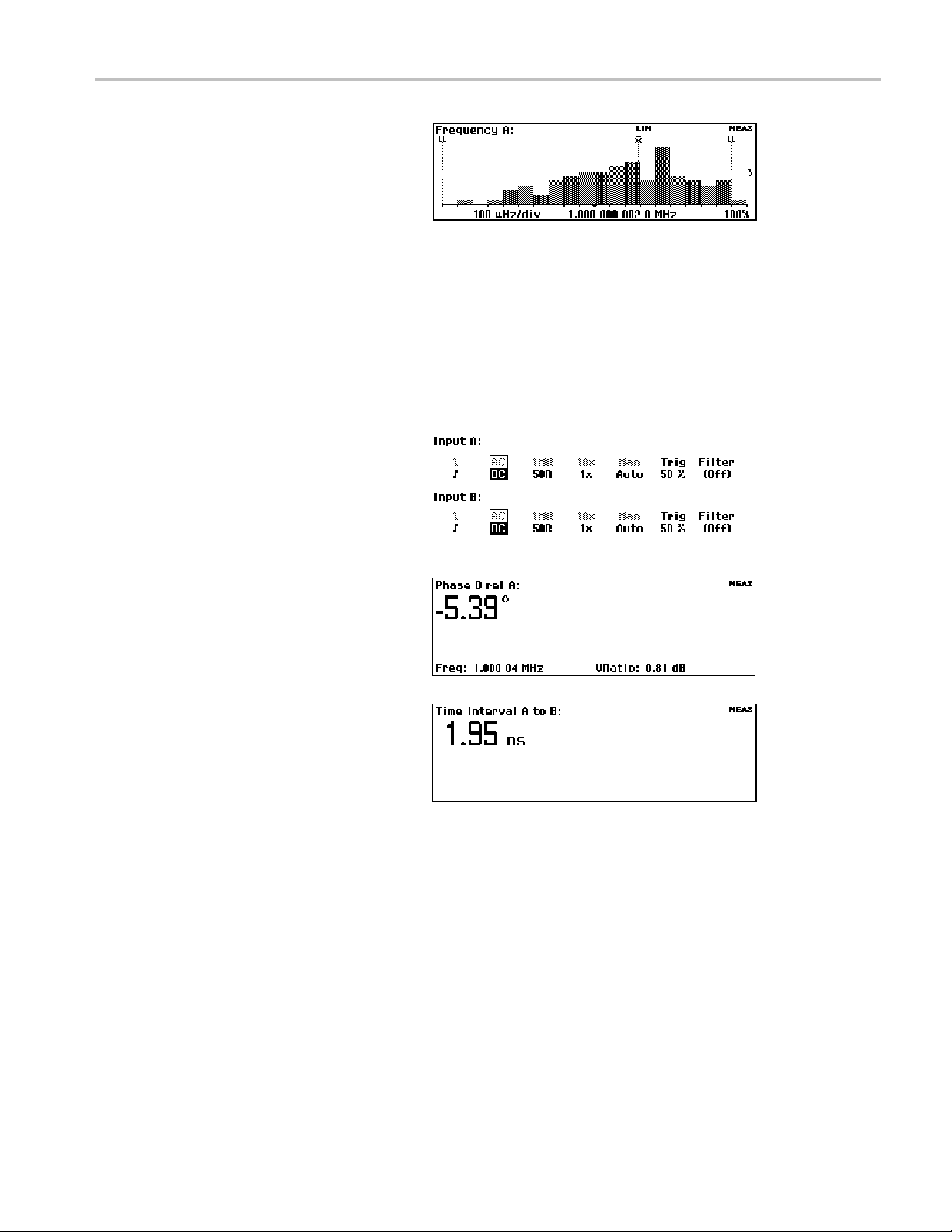
7. リミット設定を他のリードアウトに追
加して表示することもできます。例
えば、ヒストグラムのリー
示されるまで、Analyze ボタンを繰り
返し押します。
8. リミット・テストを停止(無効)にする
には、Math/Limit > Limit Behavior
>Offを押します。
2 チャンネルの測定
必要条件:機器をデフォルト設定にリセットします。 (14 ページ 「デフォルト設定のリストア」 参照)。
1. Input A および Input B のボタンを
押して、測定に適し
とを確認します。この例では、入力
設定は同じ内容です。
使用例
ドアウトが表
た設定であるこ
2. 信号を入力 A および B に接続しま
す。
3. Meas を押し
選択します。A 入力と比較した B 入
力の位相差が表示されます。
4. Meas を押して、Time > Time Inter-
val > A to B を選択します。 Input A
の立上りエッジから Input B の立上
りエッジまでのタイム・インターバル
が表示されます。
Input C の測定
Input C 高周波プリスケーラを持つ機器(FCA3000 シリーズ、FCA3100 シリーズ)またはダウン・コンバータ
を持つ機器(MCA3000 シリーズ)では、C 入力の測定サブセットが使用可能です。これらの測定項目は、周
波数、周波数レシオ(C と A、および C と B)、周波数バースト、および周期(平均)です。機器のメニューに
Input C が追 加されます。
て、Phase > B Rel A を
通常の手順で Input C の測定を行います。Input C での測定に関する詳細は、『FCA3000 シリーズ、FCA3100
シリーズ、および MCA3000 シリーズ・ユーザ・マニュアル』を参照してください。
FCA3000、FCA3100、および MCA3000 シリーズ・クイック・スタート・ユーザ・マニュアル 17
Page 68
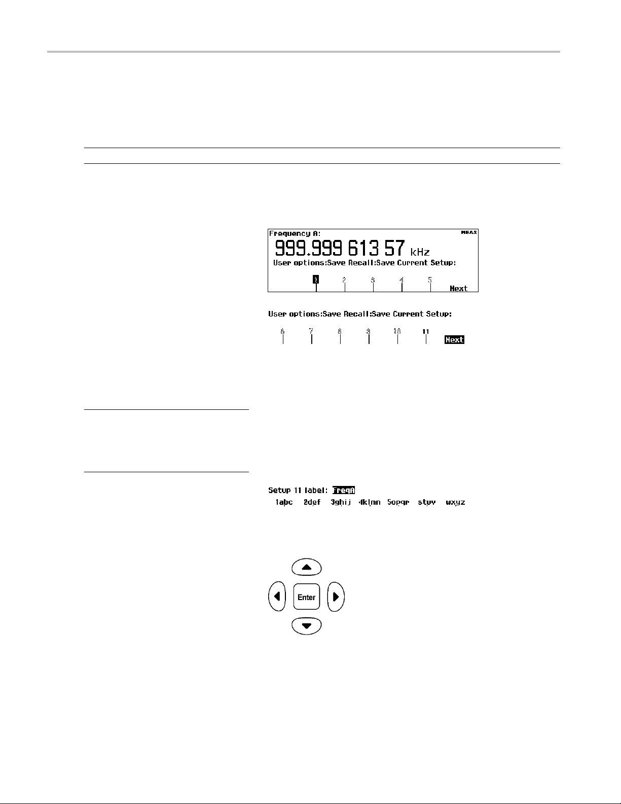
使用例
機器の設定値の保存
機器では、20 の設定情報を不揮発メモリに保存することができます。測定項目の設定、トリガ・レベル、演算
の定数などを含めたすべての機器パラメータが保存されます。保存するセットアップごとに固有の識別子で
ラベルを付けることができます(最長 7 文字)。
注: デフォルトの機器設定を復元しても、メモリに保存された設定が消去されることはありません。
1. 保存したい構成に機器を設定しま
す。
2. User Opt > Save/Recall > Setup >
Save Current Setup を押します。
3. 使用可能なメモリ
ト番号で示す)が表示されるまで、
Next を選択します。空または使用
できないメモリ
で示されます。
4. メニュー・キーを押して、メモリの番
号を選択します。
注: 内容を誤って上書きするのを防ぐ
ために、セッ
はデフォルトで保護されています。セッ
トアップ・メモリの保護に関する詳細は、
ユーザ・マ
5. メニューの
器の設定ファイルにラベルを入力し
ます(最長 7 文字)。デフォルトのラ
ベルは現
たものです。
6. ナビゲ
挿入カーソルを移動します。
7. Enter または Save/Exit を押してラ
ベル・テキストを確定し、機器の設
定を保
トアップ・メモリの 1 ~ 10
ニュアルを参照してください。
ソフトキーを使用して、機
在の測定を元に生成され
ーション・ボタンを使用して、
存します。
位置(黒いフォン
位置はグレーの文字
18 FCA3000、FCA3100、および MCA3000 シリーズ・クイック・スタート・ユーザ・マニュアル
Page 69

セットアップの呼び出し
1. User Opt > Save/Recall > Setup >
Recall Setup を押します。
2. Next メニュー・ボタンを押して、機
器のセットアップを呼び
を表示します。空の場所はグレーの
文字で示されます。
3. セットアップ・メモリのメニュー・ボタ
ンを押します。セットアップがロード
され、そのセットアッ
測定項目が表示されます。
出すメモリ
プに基づいた
使用例
FCA3000、FCA3100、および MCA3000 シリーズ・クイック・スタート・ユーザ・マニュアル 19
Page 70

接続
接続
FCA3000、FCA3100、および MCA3000 の各シリーズのベンチ機器に備わる高速 USB および GPIB バスを
利用すると、当社専用エディションの National Instruments LabVIEW SignalExpress ソフトウェアを使用して、
測定結果の収集、保存、および解析がすばやく簡単に行えます。すべての機器には、基本的な機器のコン
トロール、データ・ロギング、および解析が可能な SignalExpress の 当社 バージョンの無償コピーが付属し
ています。オプションの完全版では、詳細な信号処理、拡張解析、掃引、リミット・テスト、およびユーザによ
るステップ定義など、200 以上の機能を備えています。
SignalExpress は当社のすべてのベンチ機器を接続でき、各機器のさまざまな機能に、単一の直感的なソフト
ウェア・インタフェースを介してアクセスすることができます。単一のインタフェースにより、複数の機器を必要
とする複雑な測定、複数の機器の時間相関データ、長時間にわたるデータ・ロギングを自動化することがで
き、結果を簡単に収集し解析することができます。これらすべてを手元の PC から操作することが可能です。
オプションの TimeView™ Modulation Domain Analysis PC ソフトウェア・アプリケーション(TVA3000)を使用す
ると、機器のリモート・コントロールが可能になり、測定結果の解析と表示がグラフの選択だけで行えます。
変調、ジッタ、ワンダ、スイープの線形性、周波数可変型通信、ワイヤレス LAN、Bluetooth 周波数ホッピン
グ、VCO 周波数応答など、時間と周波数に関するほぼすべてのダイナミック変動が解析できます。例えば、
結果を生データ、統計ヒストグラム、波形グラフ(オシロスコープを使用しているかのように)、また FFT のス
ペクトル・グラフとして表示できます。TimeView ではさらに、変調度や周波数変調指数などの変調パラメー
タの解析も行えます。TimeView は、当社 Web サイト(www.tektronix.com)から 30 日間のトライアル版をダ
ウンロードできます。
20 FCA3000、FCA3100、および MCA3000 シリーズ・クイック・スタート・ユーザ・マニュアル
Page 71

x
FCA3000 和 FCA3100 系列定时器/计数器/分析仪
MCA3000 系列微波计数器/分析仪
ZZZ
快速入门用户手册
*P071278901*
071-2789-01
Page 72

Page 73

xx
FCA3000 和 FCA3100 系列定时器/计数器/分析仪
MCA3000 系列微波计数器/分析仪
ZZZ
快速入门用户手册
www.tektronix.com
071-2789-01
Page 74

Copyright © Tektronix. 保留所有权利。许可软件产品由 Tektronix、其子公司或提供商所有,受国家版权
法及国际条约规定的保护。
Tektronix 产品受
有以前出版的资料中的信息。保留更改技术规格和价格的权利。
TEKTRONIX 和 TEK 是 Tektronix, Inc. 的注册商标。
LabVIEW、National Instruments、NI 和 SignalExpress 是 National Instruments 的商标。
TimeView 是 Pendulum Instruments AB 的商标。
美国和外国专利权(包括已取得的和正在申请的专利权)的保护。本文中的信息将取代所
Tektronix 联系信息
Tektronix, Inc.
14150 SW Karl Braun Drive
P.O. Box 500
Beaverton, OR 97077
USA
有关产品信息、销售、服务和技术支持:
在北 美地区,请拨打 1-800-833-9200。
其他地区用户请访问 www.tektronix.com,以查找当地的联系信息。
Page 75

保证声明
Tektronix 保证,本产品自发货之日起三 (3) 年内不会出现材料和工艺缺陷。 如果在保修期内证明任何此类
产品有缺陷,Tektronix 将会选择对缺陷产品进行维修或更换,不收部件和人工费用。 Tektronix 作保证用
途的部件、模块和更换产品可能是全新的,或者经修理具有相当于新产品的性能。 所有更换的部件、模块和
产品将成为 Tektronix 的财产。
为得到本保证声明承诺的服务,客户必须在保修期内向 Tektronix 通报缺陷,并为服务的履行做适当安排。
客户应负责包装缺陷产品并托运到 Tektronix 指定的维修中心,同时预付运费。 如果产品运送到 Tektronix
维修中心所在国之内的地点,Tektronix 应支付向客户送返产品的费用。 如果产品送返到任何其他地点,客
户应负责支付所有的运费、关税、税金及任何其他费用。
本保证声明不适用于由于使用不当或者维护保养不当或不足所造成的任何缺陷、故障或损坏。 Tektronix 在
本保证声明下没有义务提供以下服务:a) 修理由非 Tektronix 服务代表人员对产品进行安装、修理或维护
所导致的损坏;b) 修理由于使用不当或与不兼容的设备连接造成的损坏;c) 修理由于使用非 Tektronix 提
供的电源而造成的任何损坏或故障;d) 维修已改动或者与其他产品集成的产品(如果这种改动或集成会增加
产品维修的时间或难度)。
本保证由 TEKTRONIX 关于本产品而订立,用于替代任何其他的明示或暗示的保证。 TEKTRONIX 及其供应商拒
绝对用于特殊目的的适销性或适用性做任何暗示的保证。 对于违反本保证的情况,TEKTRONIX 负责修理或更
换有缺陷产品是提供给客户的唯一和独有的补救措施。 无论 TEKTRONIX 及其供应商是否被预先告知可能发
生任何间接、特殊、意外或引发的损坏,TEKTRONIX 及其供应商对这些损坏都不负有责任。
[W4 – 15AUG04]
Page 76

Page 77

目录
常规安全概要.............................................................................................. iii
符合性信息 ................................................................................................. v
前言....................................................................................................... viii
安装........................................................................................................ 1
认识仪器................................................................................................... 3
应用示例.................................................................................................. 12
连接....................................................................................................... 18
目录
EMC 符合性............................................................................................ v
安全符合性............................................................................................ vi
环境注意事项 ......... . . . . . . . . . . . ........... . . . . . . . . . . . ........... . . . . ................................ vii
主要功能 ............................................................................................. viii
文档 ................................................................................................... ix
本手册中使用的约定........ . . . . . . . . . . ........... . . . . . . . . . . . ........... .. . ............................ ix
打开仪器包装 ......... . . . . . . . . . . . ........... . . . . . . . . . . . ........... . . . . ................................ 1
操作注意事项 ......... . . . . . . . . . . . ........... . . . . . . . . . . . ........... . . . . ................................ 1
接通和断开仪器电源........ . . . . . . . . . . ........... . . . . . . . . . . . ........... .. . ............................ 2
功能检查 .............................................................................................. 2
前面板................................................................................................. 3
后面板................................................................................................. 4
输入连接器............................................................................................ 5
控件 ................................................................................................... 6
主屏幕................................................................................................. 9
恢复默认设置 ......... . . . . . . . . . . . ........... . . . . . . . . . . . ........... . . . . ............................... 12
基本测量 ............................................................................................. 12
数学测量 ............................................................................................. 13
门限测试 ............................................................................................. 13
双通道测量
输入 C 测量 .......................................................................................... 15
保存仪器设置 ......... . . . . . . . . . . . ........... . . . . . . . . . . . ........... . . . . ............................... 16
........................................................................................... 15
FCA3000、FCA3100 和 MCA3000 系列快速入门用户手册 i
Page 78

目录
ii FCA3000、FCA3100 和 MCA3000 系列快速入门用户手册
Page 79

常规安全概要
详细阅读下列安全性预防措施,以避免人身伤害,并防止损坏本产品或与本产品连接的任何产品。
为避免可能的危险,请务必按照规定使用本产品。
只有合格人员才能执行维修过程。
使用此产品时,可能需要接触到大系统的其他部分。请阅读其他组件手册的安全性部分中的有关操作
此系统的警告和注意事项。
避免火灾或人身伤害
常规安全概要
使用合适的电源线。 请
正确连接并正确断开
将产品接地。 本产品
本产品的输入端或输出端进行连接之前,请务必将本产品正确接地。
只使用本产品专用并经所在国家/地区认证的电源线。
连接。
通过电源线的接地导线接地。为避免电击,必须将接地导线与大地相连。在对
探头或测试导线连接到电压源时请勿插拔。
遵守所有终端额定值。 为避免火灾或电击,请遵守产品上的所有额定值和标记。在对产品进行连
接之前,请首先查阅产品手册,了解有关额定值的详细信息。
输入端的额定值不适用于连接到市电或 II、III 或 IV 类型电路。
对任何终端(包括公共终端)施加的电压不要超过该终端的最大额定值。
断开电源。 电源线可以使产品断开电源。不要阻挡电源线;用户必须能随时触及电源线。
切勿开盖操作。 请勿在外盖或面板打开时运行本产品。
怀疑产品出现故障时,请勿进行操作。 如果怀疑本产品已损坏,请让合格的维修人员进行检查。
远离外露电路。 电源接通后,请勿接触外露的线路和元件。
请勿在潮湿环境下操作。
请勿在易燃易爆的环境中操作。
请保持产品表面清洁干燥。
请适当通风。
有关如何安装产品使其保持适当通风的详细信息,请参阅手册中的安装说明。
FCA3000、FCA3100 和 MCA3000 系列快速入门用户手册 iii
Page 80
常规安全概要
本手册中的术语
本手册中可能出现以下术语:
警告: “警告”声明指出可能会造成人身伤害或危及生命安全的情况或操作。
注意: “注意”声明指出可能对本产品或其他财产造成损坏的情况或操作。
产品上的符号和术语
产品上可能出现以下术语:
“危险”表示当您阅读该标记时会立即发生的伤害。
“警告”表示当您阅读该标记时不会立即发生的伤害。
“注意”表示可能会对本产品或其他财产带来的危险。
产品上可能出现以下符号:
iv FCA3000、FCA3100 和 MCA3000 系列快速入门用户手册
Page 81

符合性信息
本部分列出仪器遵循的 EMC(电磁兼容性)、安全和环境标准。
EMC 符合性
EC 一致性声明 - EMC
符合 2004/108/EC 指令有关电磁兼容性的要求。 经证明符合《欧洲共同体官方公报》中所列的以下
技术规范:
符合性信息
EN 61326-1:2006,EN 61326-2-1:2006: 测量、控制和实验室用电气设备的 EMC 要求。
CISPR 11:2003。 放射和传导辐射量,组 1,A 类
IEC 61000-4-2:2001。 静电放电抗扰性
IEC 61000-4-3:2002。 射频电磁场抗扰性
IEC 61000-4-4:2004。 电气快速瞬变/突发
4
抗扰性
IEC 61000-4-5:2001。 电源线路浪涌抗扰性
IEC 61000-4-6:2003。 传导射频抗扰性
IEC 61000-4-11:2004。 电压骤降和中断抗扰性
4
5
EN 61000-3-2:2006: 交流电源线谐波辐射
EN 61000-3-3:1995: 电压变化、波动和闪变
欧洲联系方式:
Tektronix UK, Ltd.
Western Peninsula
Western Road
Bracknell, RG12 1RF
1
本产品仅在非居民区内使用。 在居民区内使用可能造成电磁干扰。
2
当该设备与测试对象连接时,可能产生超过此标准要求的辐射级别。
3
为确保符合上面列出的 EMC 标准,应使用高质量的屏蔽接口电缆。
4
如果在 A 或 B 输入通道上施加 10 MHz 0.1 Vp-p 正弦波信号,则当仪器置于 IEC 61000-4-3 和 IEC 61000-4-6
测试中定义的磁场和信号环境时,仪器的频率读数值通常可超出固有基准方差,达到 ±1 Hz 的差异。
5
性能标准 C 适用于 70%/25 循环电压骤降以及 0%/250 循环电压中断测试电平 (IEC61000-4-11)。
123
澳大利亚/新西兰一致性声明 – EMC
根据 ACMA,符合 Radiocommunications Act(无线电通信法)有关 EMC 规定的以下标准:
CISPR 11:2003。 放射和传导辐射量,组 1,A 类,依照 EN 61326-1:2006 和 EN 61326-2-1:2006。
澳大利亚/新西兰联系方式:
Baker & McKenzie
FCA3000、FCA3100 和 MCA3000 系列快速入门用户手册 v
Page 82

符合性信息
Level 27, AMP Centre
50 Bridge Stree
Sydney NSW 2000, Australia(澳大利亚)
安全符合性
加拿大认证
CAN/CSA-C22.2 No. 61010-1:2004。 测量、控制和实验室用电气设备的安全性要求。 第 1 部分。
设备类型
测试和测量设备。
安全级别
1级-接地产品。
污染度说明
t
对产品周围和产品内部环境中可能出现的污染的一种量度。 通常认为产品的内部环境与外部环境相
同。 产品只应该在其规定环境中使用。
污染度 1。 无污染或仅出现干燥、非传导性污染。 此类别的产品通常进行了封装、密封或被置
于干净的房间中。
污染度 2。 通常只发生干燥、非传导性污染。 偶尔会发生由凝结引起的临时传导。 典型的办
公室/家庭环境属于这种情况。 只有当产品处于非使用状态时,才会发生临时凝结。
污染度 3。 传导性污染,或由于凝结会变成传导性污染的干燥、非传导性污染。 此类场所为温
度和湿度不受控制的建有遮盖设施的场所。 此类区域不受阳光、雨水或自然风的直接侵害。
污染度 4。 通过传导性的尘埃、雨水或雪而产生永久传导性的污染。 户外场所通常属于这种
情况。
污染度
污染度
2(如 IEC 61010-1 中定义)。 注意: 仅适合在室内使用。
vi FCA3000、FCA3100 和 MCA3000 系列快速入门用户手册
Page 83

环境注意事项
本部分提供有关产品对环境影响的信息。
产品报废处理
回收仪器或元件时,请遵守下面的规程:
设备回收: 生产本设备需要提取和使用自然资源。 如果对本产品的报废处理不当,则该设备中包含
的某些物质可能会对环境或人体健康有害。 为避免将有害物质释放到环境中,并减少对自然资源的
使用,建议采用适当的方法回收本产品,以确保大部分材料可以得到恰当的重复使用或回收。
此符号表示该产品符合欧盟有关废旧电子和电气设备 (WEEE) 以及电池的 2002/96/EC 和
2006/66/EC 号指令所规定的相关要求。 有关回收方式的信息,请查看 Tektronix 网站
(www.tektronix.com) 上的 Support/Service(支持/服务)部分。
有害物质限制
根据其分类,本产品属于监视控制设备,不在 2002/95/EC RoHS 指令范围之列。
符合性信息
FCA3000、FCA3100 和 MCA3000 系列快速入门用户手册 vii
Page 84

前言
前言
本手册介绍了 FCA3000 系列、FCA3100 系列及 MCA3000 系列仪器的安装和基本操作。 有关详细信
息,请参阅《FCA3000 系列、FCA3100 系列和 MCA3000 系列用户手册》(产品光盘上的 PDF 文件)。
本手册适用于以下仪器:
FCA3000 系列: FCA3000、FCA3003 和 FCA3020
FCA3100 系列: FCA3100、FCA3103 和 FCA3120
MCA3000 系列: MCA3027 和 MCA3040
主要功能
测量频率范围达 40
市面上最快的微波计
业界唯一带图形显示
高分辨率,单次可
同时显示信号频率
触发灵敏度为 15
电压分辨率达 1
USB/GPI
零停滞时间频率
最佳的恒温晶
MCA300
0.5 Hz 至
10 MHz
测量统计模
直方图模式
B 总线传输速度高,每秒多达 15k 次测量(块模式)
0 系列提供微波 CW 频率测量以及低至 40 ns 的极短突发脉冲测量
50 MHz 的可编程脉冲输出( FCA3100 系列)
基准输出振荡器
达 50 ps(时间),即相当于 12 位/秒(频率)
和电压参数
mVrms,从直流到 200 MHz
mV
/周期测量
体振荡器 (OCXO) 时基选项(1.5 E-8/年)
式
GHz
数器(采集时间为 25 ms)
的频率计数器
趋势图模
前后输入
viii FCA3000、FCA3100 和 MCA3000 系列快速入门用户手册
式
连接选项
Page 85

文档
查看以下内容,了解在哪些地方可以获取本产品的各类信息。
需获取的信息 使用的文档
安装和操作(概述) 快速入门用户手册。 提供一般的操作信息。
详细的操作和用户界面帮助 用户手册(位于文档浏览器光盘上)。 提供有关仪器功能使
程序员命令 程序员手册(位于文档浏览器光盘上)。 包含 GPIB 命令语
分析和连接工具 National Instruments SignalView Express 光盘和连接安装
本手册中使用的约定
本手册中使用了以下图标。
前言
用的详细说明。
法。
说明(位于文档浏览器光盘)。
顺序步骤 前面板电源 连接电源
用 > 符号分隔一
> 正频宽 > A)的意思是依次按下 Meas(测量)按钮、Pulse(脉冲)菜单按钮、Width Positive
(正频宽)菜单按钮和 A 菜单按钮
系列按钮的按击操作。 例如,Meas > Pulse > Width Positive > A(测量>脉冲
USB
FCA3000、FCA3100 和 MCA3000 系列快速入门用户手册 ix
Page 86

前言
x FCA3000、FCA3100 和 MCA3000 系列快速入门用户手册
Page 87

安装
打开仪器包装
打开仪器包装,检查是否收到列为“标准附件”的所有物品。 请访问 Tektronix 网站 (www.tektronix.com) 了解最新信息、推荐的附件、仪器选件和升级。
标准附件
附件
FCA3000 和 FCA3100 系列定时器/计数器/分析仪、MCA3000 系列微波计数器/分
析仪快速入门用户手册(英文/简体中文/日文)
产品文档光盘
NI LabVIEW SignalExpress 光盘
电源线 因国家/地区而异
类型 N 针型至 BNC 适配器(仅适用于 FCA3003、FCA3020、FCA3103 和 FCA3120)
校准证明
安装
Tektronix 部件
号
071-2787-xx
063-4288-xx
063-4253-xx
不适用
不适用
操作注意事项
请验证要使用仪器的区域是否符合以下操作要求:
要求 说明
间隙
线路电源
温度 工作状态: 0℃ 至 +50℃(32℉ 至 122℉)
湿度
海拔高度(最大值) 2000 米(6500 英尺)
最大无损输入电压,输入 A
和输入 B
最大无损输入电平,输入 C
顶部和底部: 0 毫米(0 英寸)
左右两侧: 51 毫米(2 英寸)
后部:51毫米(2英寸)
100–240VAC±10%,CATII:50–400Hz±10%:40W
非工作状态: –40℃ 至 +71℃(–40℉ 至 +160℉)
+10℃至+30℃(50℉至86℉):5%至95%
+30℃ 至 +40℃(86℉ 至 104℉): 5% 至 75%
+40℃ 至 +50℃(104℉ 至 122℉): 5% 至 45%
50 Ω: 12 V
1 MΩ,1X 衰减器: 350 V (DC + AC pk) 至 440 Hz,在 1 MHz 时
降至 12 V
1 MΩ,10X 衰减器: 350 V (DC + AC pk) 至 440 Hz,在 1 MHz 时
降至 12 V
FCA3003、FCA3103: 12 V
FCA3020、FCA3120: +27 dBm (5 V
MCA3027、MCA3040: +27 dBm (5 V
,35 V峰值,占空比低于 0.1%
rms
rms
rms
(+34 dBm)
rms
rms
rms
)
)
FCA3000、FCA3100 和 MCA3000 系列快速入门用户手册 1
Page 88

安装
接通和断开仪器电源
本仪器使用带接地或近地中性导线的单相电源。 ( 见第1页,
线提供保护性接地对于安全操作十分重要。
功能检查
1. 接通仪器电源
2. 按下 User Opt > Test(用户选项 > 测试)。
操作注意事项
)通过电源线中的接地导
3. 按下 Test Mode(测试模式)菜单按钮并选择 All(全部)。
4. 按下 Start test(开始测试)菜单按钮。 检查是否通过了所有测试。
5. 按下 OK(确定)菜单按钮返回到上一个测量显示。
6. 将一根 50 Ω 电缆从后面板上的 10 MHz Output(10 MHz 输出)连接器连接到前面板上的 Input
A(输入 A
7. 按下 Inp
8. 按下 Mea
)连接器上。
ut A(输入 A)并选择 50 Ω 输入阻抗。
s>Freq>Freq>A(测量 > 频率 > 频率 > A)。 仪器显示的值应该为 10 MHz。
2 FCA3000、FCA3100 和 MCA3000 系列快速入门用户手册
Page 89

认识仪器
前面板
认识仪器
1. 电源按钮( 见第6页,
2. 主屏幕( 见第9页,
3. 测量按钮( 见第6页,
4. 导航按钮( 见第7页,
5. 输入连接器( 见第5页,
6. 键盘按钮( 见第7页,
电源按钮
主屏幕
测量按钮
导航按钮
小键盘按钮
)
)
)
)
输入连接器
)
)
FCA3000、FCA3100 和 MCA3000 系列快速入门用户手册 3
Page 90

认识仪器
后面板
1. 脉冲输出连接器(仅适用于 FCA3100 系列)。 ( 见第5页,
2. ID 标签,包括型号、序列号、所安装的选件和仪器电源额定值。
3. 线路电源连接器。
4. 用 于连接 PC 的 USB 2.0 12 Mb/s 端口 。
5. 用于连接控制器的 GPIB 端口。
6. 可选输入连接器(工厂安装的选件,用于将前面板输入连接器移至后面板)。 不适用于 MCA3000
系列仪器。 (
7. 外部启动输入
择主输入 A 和 B 进行测量启动。 ( 见第5页,
8. 外部基准输入连接器(如果在 Settings(设置)菜单中将 Measurement Reference(测量基准)
设置为 Auto(自动),则只要存在有效的信号,此输入就会自动选中)。 ( 见第5页,
9. 10 MHz 输出连接器。 提供源自活动测量基准(内部或外部基准)的基准信号。 测量基准源在
ngs(设置)菜单中设定。 ( 见第5页,
Setti
见第5页,
连接器(用于外部启动(同步)测量)。 另外,也可从 Settings(设置)菜单中选
防止 ESD
)
防止 ESD
防止 ESD
)
防止 ESD
)
)
防止 ESD
)
4 FCA3000、FCA3100 和 MCA3000 系列快速入门用户手册
Page 91

输入连接器
认识仪器
1. 输入 A 和 B 连接器以
2. Gate(选通)指
3. 输入 C 预定标器(3
40 GHz,MCA3000 系列),用于测量较高的频率。
说明: 带有选件 RP 的仪器在后面板上有输入连接器(仅适用于 FCA3000 系列和 FCA3100 系列仪
器)。 Gate(
示器。 当计数器在统计输入周期数时,GATE(选通)指示器就会亮起。
选通)和 Trig(触发)A/B LED 指示器仍位于前面板上。
及输入触发指示器。
GHz 或 20 GHz,FCA3000 系列和 FCA3100 系列)或下变频器(27 GHz 或
防止 ESD
注意: 直接静电放电可能会损坏仪器输入端。 要了解如何避免这种损坏,请阅读以下信息。
静电放电 (ESD) 是操作
较大的静电放电直接进入信号输入端仍有可能损坏仪器。 为避免损坏仪器,请在对仪器连接任何电
缆之前使用以下方法消除您身上以及测试电缆中所带的静电:
连接和断开电缆时,佩戴接地的防静电腕带以释放您身上所带的静电。
工作台上闲置未连接的电缆会积累大量静电电荷。 对准备测试的仪器或设备连接电缆之前,将电
缆的中心导线暂时接地,
仪器上。
任何电子设备时都需注意的事项。 虽然仪器在设计时就带有 ESD 保护,但
或将一端连接 50 Ω 终端,以便放掉电缆上的静电,然后再将其连接到
FCA3000、FCA3100 和 MCA3000 系列快速入门用户手册 5
Page 92
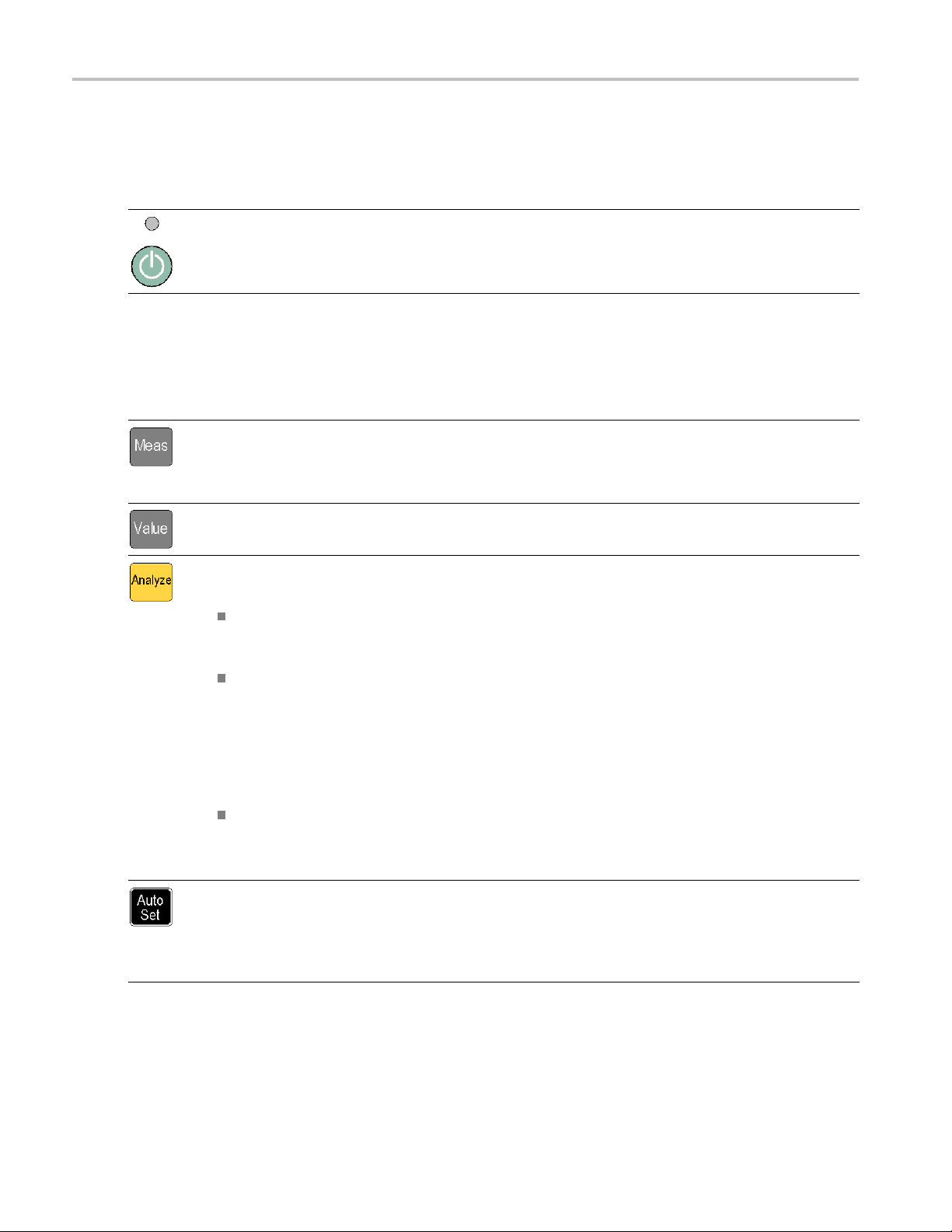
认识仪器
控件
电源按钮
项目 说明
电源按钮是一种切换式二次电源开关。 仪器中有一部分会在线路电源接通后就立即保持开
启状态,通过该按钮上方的红色 LED 进行指示。 按电源按钮即可接通或断开仪器电源。
测量按钮
使用测量按钮可以选择并显示测量值。
项目 说明
使用 Meas(测量)按钮可在屏幕底部显示仪器测量菜单。 按下某一菜单项正下方的菜
单按钮可选择该菜单项并根据需要打开子菜单。
典型的测量值包括频率、周期、时间、脉冲、相位、总计(仅适用于 FCA3100 系列)和
电压伏特数。 可用的菜单项根据仪器型号和配置而异。
使用 Value(值)按钮可显示当前测得的数值。 仪器还会在屏幕下方显示补充测量值。
使用 Analy
下 Analyze(分析)按钮可循环出现以下统计显示模式:
Numerical display(数字显示): 仪器以数字形式显示统计数据。 统计数据读数
包括 Mean(N 个取样主测量值的移动平均值)、Max(最大值)、Min(最小值)、
P-P(峰-峰
Histog
直方图中的容器会根据测得的数据自动缩放。 门限(如果有效)和移动平均值 X 显
示为垂直虚线。 图形中心由 X 轴上的实心三角形表示。 直方图底部显示有直方图标
度因数、直方
显示当前测量值以及设定的门限。 ( 见第11页,
使用 Settings > Stat > No. Of Samples(设置 > 统计 > 取样数)菜单可设置水
平轴上的容
Trend
此模式有助于观察周期性的波动或可能的趋势。 趋势图会根据测得的数据自动缩放,
重新开始时以 0 为起点。 门限(如果有效)以水平线显示。 ( 见第11页,
显示
使用 Au
言)自动设置触发电平。 这样可以快速设置仪器以便显示测量值。
在两秒钟内按两次 Auto Set(自动设置)按钮可将大部分仪器设置(例如测量时间、运
算、过
定和误解。
ze(分析)按钮可通过三种统计分析显示模式之一显示当前测量值。 反复按
偏差)、Adev(艾伦偏差)和 Std(标准差)。 ( 见第10页,
ram display(直方图显示): 仪器以直方图形式显示连续的主测量结果。
图中心测量值和测量完成百分比值。 门限设置会影响自动缩放,以同时
直方图显示
器数量。
Plot display(趋势图显示): 仪器以趋势图形式显示连续的主测量结果。
)
数字显示
趋势图
)
to Setx(趋势图显示)按钮可为测量功能和输入信号幅度(对相对正常的信号而
滤和启动)复位到默认值。 这样是为了防止在更改测量功能或测试设置时发生锁
)
6 FCA3000、FCA3100 和 MCA3000 系列快速入门用户手册
Page 93

导航按钮
使用导航按钮可选择菜单项、增加或减小数字设定值以及清除数值。
项目 说明
导航按钮根据各仪器模式提供了多种不同的功能:
Menu mode(菜单模式): 使用向左箭头、向右箭头和 Enter(输入)按钮可显
示和选择菜单项(作为使用小键盘菜单选择按钮的替代方式)。
Numeric entry mode(数字输入模式): 使用向左箭头按钮可清除设置字段中
最右端的数字。 使用向上箭头和向下箭头按钮可增加或减小设置字段中的数值
(以 1-2-5 这种方式)。
使用 Enter(输入)按钮可接受所显示的值或菜单并返回到上一个菜单。
当仪器未显示菜单或提示输入时,请使用向上和向下箭头按钮设置 LCD 屏幕对
比度。
使用 Save/Exit(保存/退出)按钮确认当前选择并退回到上一级菜单。
使用 Esc(退出)按钮直接退回到上一级菜单而不确认当前选择。
认识仪器
小键盘按钮
使用小键盘按钮可选择菜单项并输入设定值。
项目 说明
数字按钮 使用按钮 1-0、. 和 ± 可输入数字参数值。
菜单选择按钮 使用小键盘顶行按钮(1-5 和两个空白按钮)可选择相应的屏幕菜单项。
菜单访问按钮 使用小键盘底行按钮 (6-0) 可显示该按钮对应的菜单,如 Input A(输入
A)、Input B(输入 B)、Settings(设置)等。
使用 Input A(输入 A)或 Input B(输入 B)按钮可显示所选通道的输入
通道配置。
Input A(输入 A)和 Input B(输入 B)菜单提供了与通道相关的设置,包
括触发斜率、信号耦合(交流或直流)、输入阻抗(50 Ω 或 1 MΩ)、输
入衰减(1x 或 10x)、触发模式(手动或自动)、触发电平和滤波器(频率
截止)。
FCA3000、FCA3100 和 MCA3000 系列快速入门用户手册 7
Page 94

认识仪器
项目 说明
使用 Settings(设置
Settings(设置)菜单提供了与测量相关的设置,包括测量时间(用于频率
测量)、突发脉冲(用于脉冲调制信号)、启动(条件测量开始/停止)、
触发释抑(停止触发延迟)
基基准(内部或外部)和杂项(例如输入信号超时时间段和自动触发低频设
置)。
有关这些仪器菜单和设置
列用户手册》。
使用 Math/Limit(数学/门限)按钮显示数学和门限测试配置菜单。
Math(数学)菜单提供了预定义的公式和用户定义的常数,用于对测量结果
进行数学后处理。 数学
一部分的混音器或倍增器考虑在内。
通过 Limits(门限)菜单可设置数字门限以及选择仪器报告门限违例的方
式。
使用 User Opt
User Options(用户选项)菜单提供了多个仪器设置,包括保存或调出仪器
设置(出厂默认设置或者在非易失性存储器中存储的最多二十个用户设置,
每个设置都带有唯
置(模式、地址)、仪器自检、条件脉冲输出信号设置(仅适用于 FCA3100
系列)和仪器配置信息(型号、序列号、固件和配置)。
“用户选项”菜单
请参阅《FCA3000 和 FCA3100 系列定时器/计数器/分析仪及 MCA3000 系列微
波计数器/分析仪技术参考手册》了解如果进行内部仪器校准。
使用 Hold/Run(保持/运行)按钮可控制测量值采集。 按下此按钮可在运行
(不断采集测量
仪器处于测量保持模式时,屏幕右上角的测量指示器将从 MEAS(测量)变为
HOLD(保持)。 再次按下 Hold/Run(保持/运行)按钮可继续正常(连续)
测量模式。
处于保持模式时,可以按下 Restart(重新启动)按钮进行单次测量。 仪
器进行单次测量时,屏幕右上角的测量指示器将从 HOLD(保持)变为 SING
(单次)。
使用 Res
输入信号发生更改后需要启动新测量时(尤其是使用较长的测量时间时)十
分有用。
要进行单
模式(测量指示器从 MEAS(测量)变为 HOLD(保持)),然后按下 Restart
(重新启动)按钮。 测量指示器从 HOLD(保持)变为 SING(单次),仪器
进行测量
重新启动不会影响任何仪器设置。
)按钮可显示测量设置配置菜单。
、统计(包括取样数在内的统计测量设置)、时
的完整信息,请参阅《FCA3000 系列和 MCA3000 系
处理的典型用途是转换测量值,以便将作为待测信号
(用户选项)按钮可显示用户选项配置菜单。
一的标签)、总线接口选择(USB 或 GPIB)、GPIB 总线配
还提供仪器校准功能。这种内部校准过程需要密码访问。
值)和保持(测量暂停)模式之间进行切换。
tart(重新启动)按钮可将测量值归零,然后重新进行测量。 这在
次测量,请按下 Hold/Run(保持/运行)以将仪器置于 Hold(保持)
,然后指示器恢复为 HOLD(保持)。
8 FCA3000、FCA3100 和 MCA3000 系列快速入门用户手册
Page 95

主屏幕
仪器使用单色 LCD 显示信号源、仪器测量结果(数字和图形)和菜单项。 所显示的项目内容取决于
显示模式。
测量值模式
按下 Value(值)按钮启用此模式并显示当前测量项的高分辨率数字读数。
1. 当前测量项。
认识仪器
2. 测量信号源。
3. 主测量读数。 屏
化。
4. 测量状态。 显示数学或门限测试模式(MATH(数学)或 LIM(门限))、测量状态(MEAS(测
量)、HOLD(保持)或 SING(单次)),以及当前是否从 GPIB 总线远程控制 (REM) 仪器。 在
所有显示模式
5. 门限告警读数
情符号图标显示相关的测量值和门限通过/不通过状态(测量值在门限范围内时显示笑脸,测量值
在门限范围之外时显示皱眉表情)。 当测量值超出门限时,屏幕顶部的 LIM(门限)状态文本会
闪烁,即使
(门限)指示器。
幕底部的读数显示源信号的电气信息。 读数或显示会随测量项或分析模式而变
下都会显示测量状态。
(如果有效)。 下限 (LL) 和上限 (UL) 设置显示为带有关联门限值的垂直条。 表
测量值恢复到门限范围内也会继续闪烁。 按下 Restart(重新启动)按钮可复位 LIM
FCA3000、FCA3100 和 MCA3000 系列快速入门用户手册 9
Page 96
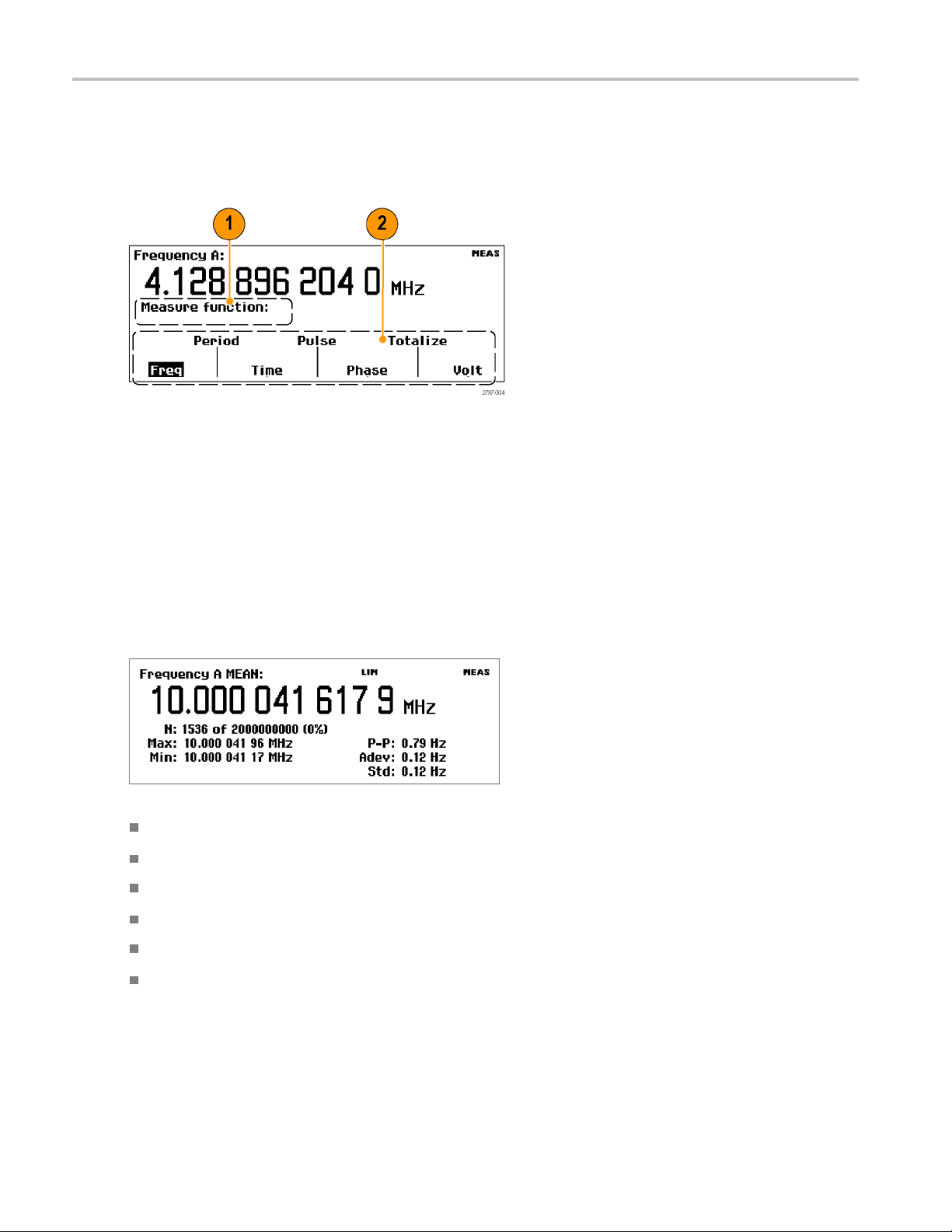
认识仪器
菜单模式
按下菜单按钮(Meas(测量)、Input A(输入 A)、Input B(输入 B)、Settings(设置)、
Math/Limit(数学/门限)或 User Opt(用户选项)),可将屏幕下方区域替换为该按钮的菜单项。
下图显示了 Meas(测量)按钮的菜单项。
1. 路径区域显示当前菜单选项的菜单路径。
2. 菜单区域显示可用的菜单选项。 按下某菜单项正下方的小键盘按钮可选择该项和/或打开下一级
别的菜单。 当前选项以反白文本显示。 另外,还可以使用导航按钮突出显示和选择菜单项。
分析模式
分析模式(可通过反复按下 Analyze(分析)按钮进行访问)用于将基本的统计分析应用于测量项,
以便通过数字、直方图或趋势图方式显示统计分析结果。
数字显示: 仪器进行连续测量并以数字统计读数显示测量结果。
MEAN: 主测量值显示 N 个取样的移动平均值。
N: 测量取样数(在 Settings > Stat (设置 > 统计)菜单中设置)。
Max、Min: 最大测量值和最小测量值。
P-P: 峰 -峰偏差。
Adev: 艾伦偏差。
Std: 标准差。
10 FCA3000、FCA3100 和 MCA3000 系列快速入门用户手册
Page 97

认识仪器
直方图显示: 仪器以直方图形式显示连续的测量结果。 水平轴上的容器数量在 Settings > Stat
(设置 > 统计)菜单中设置。
1. 上限和下限告警电平(如果有效)。 当门限测试处于活动状态时,仪器会自动缩放图形以显示直
方图和门限。 仪器仅使用门限范围内的数据进行自动缩放;对于可见图形区域之外的测量值,显
示屏左边沿或右边沿将会显示一个箭头。
2. 移动平均测量值 (X
3. 测量完成的百分比。
4. 图形中心(以黑色三角形标记)和相应频率。
5. 每格的图形水平标度。 门限告警(如果有效)将标度设置为显示当前测量值和门限设置。 仪器
根据测得的数据持续自动缩放直方图容器。
)。
趋势图显示: 仪器进行连续测量并按时间的发展绘制测量值的点线图。 此模式有助于观察波动或测
量值的偏差趋
(如果激活 Run(运行))。 趋势图会根据测得的数据连续自动缩放,重新启动时以 0 为起点。 门
限告警(如果有效)以水平线显示。
1. 趋势图显示的上段和下段频率范围。 趋势图会根据测得的数据持续自动缩放以显示测量趋势值。
势。 设定的取样数完成后,趋势图将会停止(如果激活 Hold(保持))或者重新启动
2. 测量完成的百分比。
3. 每格的水平单位。
4. 门限告警电平(如果有效)。 当门限测试处于活动状态时,仪器会设置图形标度以显示测量趋势
图和门限值(水平虚线)。
FCA3000、FCA3100 和 MCA3000 系列快速入门用户手册 11
Page 98
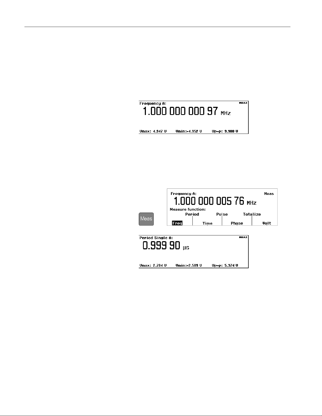
应用示例
应用示例
本部分示例的假设条件如下(除非另有说明):1 MHz 的信号;使用 50 Ω 电缆与仪器相连的 5 Vpp
方波信号源;输入信号电平和频率在可接受的范围内。
恢复默认设置
1. 按下 User Opt > Save/Recall >
Setup > Recall Setup > Default
(用户选项 > 保存/调出 > 设
置 > 调出设置 > 默认设置)可
调出(加载)仪器默认设置。 仪
器默认显示 Frequency(频率)
测量项。
基本测量
前提条件: 将仪器
1. 按下 Meas(测
surement(测量)菜单。
2. 使用菜单项下方的菜单软键选择
测量项。
例如,选择 Period > Single > A
(周期>单次>A)可显示输
入 A 的周期测量。
复位到默认设置。 ( 见第12页,
量)以打开 Mea-
恢复默认设置
>
)
12 FCA3000、FCA3100 和 MCA3000 系列快速入门用户手册
Page 99
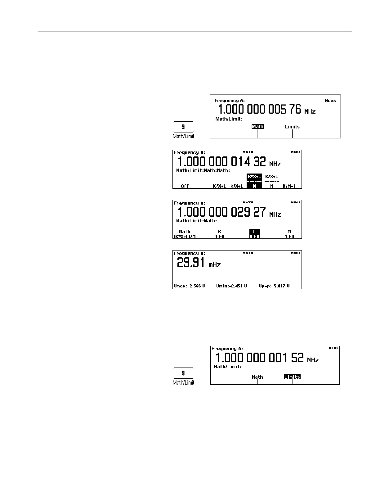
数学测量
内置的数学函数可用于应用后处理运算,例如对测量值进行缩放和偏置。 此功能的其中一个用途便
是显示理想值的偏差。 这称为偏置。 公式中的 X 值代表仪器测量值。
应用示例
前提条件: 将仪器复位到默认设置。 ( 见第12页,
1. 按下 Math/Limit(数学/门限)
以打开 Math and Limits(数学和
门限)菜单。
>
2. 选择 Math > Math Off >
(K*X+L)/M
算 > (K*X+L)/M)。
3. 选择 L 并输入 –1 EE6。
4. 反复按下 Sa
出)以退出各级菜单并返回到测
量读数。 仪器会显示 1 MHz 的
偏差频率(在
赫)。
(数学 > 关闭数学运
ve/Exit(保存/退
本例中为 29.91 毫
恢复默认设置
)
门限测试
此示例测试频率门限,但大多数测量都可设置测试门限。
1. 将仪器复
第12页,
2. 按下 Math/Limit(数学/门限)
并选择 Limits(门限)。
FCA3000、FCA3100 和 MCA3000 系列快速入门用户手册 13
位到默认设置。 ( 见
恢复默认设置
)
>
Page 100

应用示例
3. 按下 Limit Behav
限行为关闭)并选择 Alarm_Stop
(告警_停止)。 仪器会返回到
上一个菜单并将 Limit
(门限行为)菜单标签更改为
Alarm_Stop(告警_停止)。
4. 验证 Limit Mode(门限模式)是
否设置为 Range(范
5. 选择 Lower Limit (下限)并输
入测量下限值。 按下 Enter(输
入)或 Save/Exit(保存/退出)
以接受该值。
重复执行此步骤以设置 Upper
Limit(上限)值。
6. 反复按下 Save/Exit (保存/退
出)以退出菜单系统并返回到测
量显示。 然后按下 Restart(重
新启动)。
范围模式门限测试读数使用垂直
线表示下限和上限值,使用笑脸
表情符号表示测量值在门限范围
内。
ior Off(门
Behavior
围)。
在所显示的门限之外的测量值将
以皱眉表情符号和闪烁的 LIM(门
限)状态指示器表示。
超出门限测试标度的测量值将以屏
幕左边沿或右边沿的箭头表示。
仪器仅使用门限范围内的数据进
行自动缩放。
7. 您也可以将门限设置显示为其他
读数的一部分。 例如,反复按下
Analyze(分析)按钮,直到仪器
显示直方图读数为止。
8. 要停止(禁用)门限测试,请按
ath/Limit > Limit Behavior
下 M
> Off(数学/门限 > 门限行为
>关闭)。
14 FCA3000、FCA3100 和 MCA3000 系列快速入门用户手册
 Loading...