


EXP-16 and EXP-16/A
User’s Guide
A GREATER MEASURE OF CONFIDENCE

WARRANTY
Hardware
Keithley Instruments, Inc. warrants that, for a period of one (1) year from the date of shipment (3 years for Models 2000,
2001, 2002, 2010 and 2700), the Keithley Hardware product will be free from defects in materials or workmanship. This
warranty will be honored provided the defect has not been caused by use of the Keithley Hardware not in accordance with
the instructions for the product. This warranty shall be null and void upon: (1) any modification of Keithley Hardware that
is made by other than Keithley and not approved in writing by Keithley or (2) operation of the Keithley Hardware outside
of the environmental specifications therefore.
Upon receiving notification of a defect in the Keithley Hardware during the warranty period, Keithley will, at its option,
either repair or replace such Keithley Hardware. During the first ninety days of the warranty period, Keithley will, at its
option, supply the necessary on site labor to return the product to the condition prior to the notification of a defect. Failure
to notify Keithley of a defect during the warranty shall relieve Keithley of its obligations and liabilities under this
warranty.
Other Hardware
The portion of the product that is not manufactured by Keithley (Other Hardware) shall not be covered by this warranty,
and Keithley shall have no duty of obligation to enforce any manufacturers' warranties on behalf of the customer. On those
other manufacturers’ products that Keithley purchases for resale, Keithley shall have no duty of obligation to enforce any
manufacturers’ warranties on behalf of the customer.
Software
Keithley warrants that for a period of one (1) year from date of shipment, the Keithley produced portion of the software or
firmware (Keithley Software) will conform in all material respects with the published specifications provided such Keithley
Software is used on the product for which it is intended and otherwise in accordance with the instructions therefore.
Keithley does not warrant that operation of the Keithley Software will be uninterrupted or error-free and/or that the Keithley
Software will be adequate for the customer's intended application and/or use. This warranty shall be null and void upon any
modification of the Keithley Software that is made by other than Keithley and not approved in writing by Keithley.
If Keithley receives notification of a Keithley Software nonconformity that is covered by this warranty during the warranty
period, Keithley will review the conditions described in such notice. Such notice must state the published specification(s)
to which the Keithley Software fails to conform and the manner in which the Keithley Software fails to conform to such
published specification(s) with sufficient specificity to permit Keithley to correct such nonconformity. If Keithley determines that the Keithley Software does not conform with the published specifications, Keithley will, at its option, provide
either the programming services necessary to correct such nonconformity or develop a program change to bypass such
nonconformity in the Keithley Software. Failure to notify Keithley of a nonconformity during the warranty shall relieve
Keithley of its obligations and liabilities under this warranty.
Other Software
OEM software that is not produced by Keithley (Other Software) shall not be covered by this warranty, and Keithley shall
have no duty or obligation to enforce any OEM's warranties on behalf of the customer.
Other Items
Keithley warrants the following items for 90 days from the date of shipment: probes, cables, rechargeable batteries, diskettes,
and documentation.
Items not Covered under Warranty
This warranty does not apply to fuses, non-rechargeable batteries, damage from battery leakage, or problems arising from
normal wear or failure to follow instructions.
Limitation of Warranty
This warranty does not apply to defects resulting from product modification made by Purchaser without Keithley's express
written consent, or by misuse of any product or part.

Disclaimer of Warranties
EXCEPT FOR THE EXPRESS WARRANTIES ABOVE KEITHLEY DISCLAIMS ALL OTHER WARRANTIES,
EXPRESS OR IMPLIED, INCLUDING WITHOUT LIMITATION, ALL IMPLIED WARRANTIES OF MERCHANTABILITY AND FITNESS FOR A PARTICULAR PURPOSE. KEITHLEY DISCLAIMS ALL WARRANTIES WITH
RESPECT TO THE OTHER HARDWARE AND OTHER SOFTWARE.
Limitation of Liability
KEITHLEY INSTRUMENTS SHALL IN NO EVENT, REGARDLESS OF CAUSE, ASSUME RESPONSIBILITY FOR
OR BE LIABLE FOR: (1) ECONOMICAL, INCIDENTAL, CONSEQUENTIAL, INDIRECT, SPECIAL, PUNITIVE OR
EXEMPLARY DAMAGES, WHETHER CLAIMED UNDER CONTRACT, TORT OR ANY OTHER LEGAL THEORY,
(2) LOSS OF OR DAMAGE TO THE CUSTOMER'S DATA OR PROGRAMMING, OR (3) PENALTIES OR PENALTY
CLAUSES OF ANY DESCRIPTION OR INDEMNIFICATION OF THE CUSTOMER OR OTHERS FOR COSTS, DAMAGES, OR EXPENSES RELATED TO THE GOODS OR SERVICES PROVIDED UNDER THIS WARRANTY.
Keithley Instruments, Inc.
Sales Offices: BELGIUM: Bergensesteenweg 709 • B-1600 Sint-Pieters-Leeuw • 02-363 00 40 • Fax: 02/363 00 64
CHINA: Yuan Chen Xin Building, Room 705 • 12 Yumin Road, Dewai, Madian • Beijing 100029 • 8610-6202-2886 • Fax: 8610-6202-2892
FINLAND: Tietäjäntie 2 • 02130 Espoo • Phone: 09-54 75 08 10 • Fax: 09-25 10 51 00
FRANCE: 3, allée des Garays • 91127 Palaiseau Cédex • 01-64 53 20 20 • Fax: 01-60 11 77 26
GERMANY: Landsberger Strasse 65 • 82110 Germering • 089/84 93 07-40 • Fax: 089/84 93 07-34
GREAT BRITAIN: Unit 2 Commerce Park, Brunel Road • Theale • Berkshire RG7 4AB • 0118 929 7500 • Fax: 0118 929 7519
INDIA: Flat 2B, Willocrissa • 14, Rest House Crescent • Bangalore 560 001 • 91-80-509-1320/21 • Fax: 91-80-509-1322
ITALY: Viale San Gimignano, 38 • 20146 Milano • 02-48 39 16 01 • Fax: 02-48 30 22 74
JAPAN: New Pier Takeshiba North Tower 13F • 11-1, Kaigan 1-chome • Minato-ku, Tokyo 105-0022 • 81-3-5733-7555 • Fax: 81-3-5733-7556
KOREA: 2FL., URI Building • 2-14 Yangjae-Dong • Seocho-Gu, Seoul 137-888 • 82-2-574-7778 • Fax: 82-2-574-7838
NETHERLANDS: Postbus 559 • 4200 AN Gorinchem • 0183-635333 • Fax: 0183-630821
SWEDEN: c/o Regus Business Centre • Frosundaviks Allé 15, 4tr • 169 70 Solna • 08-509 04 679 • Fax: 08-655 26 10
SWITZERLAND: Kriesbachstrasse 4 • 8600 Dübendorf • 01-821 94 44 • Fax: 01-820 30 81
TAIWAN: 1FL., 85 Po Ai Street • Hsinchu, Taiwan, R.O.C. • 886-3-572-9077• Fax: 886-3-572-9031
28775 Aurora Road • Cleveland, Ohio 44139 • 440-248-0400 • Fax: 440-248-6168
1-888-KEITHLEY (534-8453) • www.keithley.com
4/02

EXP-16
and
EXP-IG/A
User’s
Revision
Part
E
-
Number:
Guide
April
1995
61
590

New Contact Information
Keithley Instruments, Inc.
28775 Aurora Road
Cleveland, OH 44139
Technical Support: 1-888-KEITHLEY
Monday – Friday 8:00 a.m. to 5:00 p.m (EST)
Fax: (440) 248-6168
Visit our website at http://www.keithley.com

The information contained
Instruments,
of
third parties that
patent
rights
Inc.,
of
Keithley
assumes
may
result
Instruments, hc.
in
this
manual
no
responsibility for its
from
is believed
its use.
to
be accixate and reliable. However, Keithley
use
or
No
license is granted
for
any
infringements
by
implication
of
patents
or
or
other
otherwise under any
rights
KEITHLEY INSTRUMENTS,
OR
CONSEQUENTIAL
PRODUCT
SUITABLE
Refer
All
brand
0
Copyright Keithley Instruments, Inc., 1985,1992, 1995.
All
rights reserved. Reproduction
by
Section 117
unlaw
to
fd
IS
NOT
DESIGNED
FOR
USE
IN LIFE SUPPORT OR
your
Keithley Instruments license agreement
and
product names
of
the 1976 United States
.
INC.,
DAMAGES
WITH
are
trademarks
or
adaptation
SHALL
RELATED
NOT
COMPONENTS
CRITICAL
or
registered trademarks
of
Copyright
BE LIABLE
TO
any part
Act without permission
THE
USE
OF
A
APPLICATIONS.
for
specific
of
this
FOR
ANY
SPECIAL,
OF
THIS
PRODUCT.
LEVEL
documentation beyond that permitted
OF
RELIABILITY
warranty
and liability information.
of
their respective companies.
of
the Copyright owner
WCIDENTAL,
THIS
is

S
The following safety precautions should be observed before using this product and any associated instrumentation.
Although some instruments and accessories would normally be used with non-hazardous voltages, there are situations
where hazardous conditions may be present.
This product is intended for use by qualified personnel who recognize shock hazards and are familiar with the safety
precautions required to avoid possible injury. Read and follow all installation, operation, and maintenance information
carefully before using the product. Refer to the manual for complete product specifications.
If the product is used in a manner not specified, the protection provided by the product may be impaired.
The types of product users are:
Responsible body
the equipment is operated within its specifications and operating limits, and for ensuring that operators are adequately
trained.
Operators
of the instrument. They must be protected from electric shock and contact with hazardous live circuits.
Maintenance personnel
the line voltage or replacing consumable materials. Maintenance procedures are described in the manual. The procedures explicitly state if the operator may perform them. Otherwise, they should be performed only by service personnel.
Service personnel are trained to work on live circuits, and perform safe installations and repairs of products. Only
properly trained service personnel may perform installation and service procedures.
Keithley products are designed for use with electrical signals that are rated Installation Category I and Installation
Category II, as described in the International Electrotechnical Commission (IEC) Standard IEC 60664. Most measurement, control, and data I/O signals are Installation Category I and must not be directly connected to mains voltage
or to voltage sources with high transient over-voltages. Installation Category II connections require protection for high
transient over-voltages often associated with local AC mains connections. Assume all measurement, control, and data
I/O connections are for connection to Category I sources unless otherwise marked or described in the Manual.
Exercise extreme caution when a shock hazard is present. Lethal voltage may be present on cable connector jacks or
test fixtures. The American National Standards Institute (ANSI) states that a shock hazard exists when voltage levels
greater than 30V RMS, 42.4V peak, or 60VDC are present.
age is present in any unknown circuit before measuring.
Operators of this product must be protected from electric shock at all times. The responsible body must ensure that
operators are prevented access and/or insulated from every connection point. In some cases, connections must be exposed to potential human contact. Product operators in these circumstances must be trained to protect themselves from
the risk of electric shock. If the circuit is capable of operating at or above 1000 volts,
may be exposed.
Do not connect switching cards directly to unlimited power circuits. They are intended to be used with impedance
limited sources. NEVER connect switching cards directly to AC mains. When connecting sources to switching cards,
install protective devices to limit fault current and voltage to the card.
Before operating an instrument, make sure the line cord is connected to a properly grounded power receptacle. Inspect
the connecting cables, test leads, and jumpers for possible wear, cracks, or breaks before each use.
is the individual or group responsible for the use and maintenance of equipment, for ensuring that
use the product for its intended function. They must be trained in electrical safety procedures and proper use
perform routine procedures on the product to keep it operating properly, for example, setting
afety Precautions
A good safety practice is to expect that hazardous volt-
no conductive part of the circuit
5/02
When installing equipment where access to the main power cord is restricted, such as rack mounting, a separate main
input power disconnect device must be provided, in close proximity to the equipment and within easy reach of the
operator.
For maximum safety, do not touch the product, test cables, or any other instruments while power is applied to the circuit under test. ALWAYS remove power from the entire test system and discharge any capacitors before: connecting
or disconnecting cables or jumpers, installing or removing switching cards, or making internal changes, such as installing or removing jumpers.
Do not touch any object that could provide a current path to the common side of the circuit under test or power line (earth)
ground. Always make measurements with dry hands while standing on a dry, insulated surface capable of withstanding the
voltage being measured.
The instrument and accessories must be used in accordance with its specifications and operating instructions or the
safety of the equipment may be impaired.
Do not exceed the maximum signal levels of the instruments and accessories, as defined in the specifications and operating information, and as shown on the instrument or test fixture panels, or switching card.
When fuses are used in a product, replace with same type and rating for continued protection against fire hazard.
Chassis connections must only be used as shield connections for measuring circuits, NOT as safety earth ground con-
nections.
If you are using a test fixture, keep the lid closed while power is applied to the device under test. Safe operation re-
quires the use of a lid interlock.
If or is present, connect it to safety earth ground using the wire recommended in the user documentation.
!
The symbol on an instrument indicates that the user should refer to the operating instructions located in the manual.
The symbol on an instrument shows that it can source or measure 1000 volts or more, including the combined
effect of normal and common mode voltages. Use standard safety precautions to avoid personal contact with these
voltages.
The
WARNING
associated information very carefully before performing the indicated procedure.
The
CAUTION
the warranty.
Instrumentation and accessories shall not be connected to humans.
Before performing any maintenance, disconnect the line cord and all test cables.
To maintain protection from electric shock and fire, replacement components in mains circuits, including the power
transformer, test leads, and input jacks, must be purchased from Keithley Instruments. Standard fuses, with applicable
national safety approvals, may be used if the rating and type are the same. Other components that are not safety related
may be purchased from other suppliers as long as they are equivalent to the original component. (Note that selected parts
should be purchased only through Keithley Instruments to maintain accuracy and functionality of the product.) If you
are unsure about the applicability of a replacement component, call a Keithley Instruments office for information.
To clean an instrument, use a damp cloth or mild, water based cleaner. Clean the exterior of the instrument only. Do
not apply cleaner directly to the instrument or allow liquids to enter or spill on the instrument. Products that consist
of a circuit board with no case or chassis (e.g., data acquisition board for installation into a computer) should never
require cleaning if handled according to instructions. If the board becomes contaminated and operation is affected,
the board should be returned to the factory for proper cleaning/servicing.
heading in a manual explains dangers that might result in personal injury or death. Always read the
heading in a manual explains hazards that could damage the instrument. Such damage may invalidate

Preface
1
Overview
Features
Applications
Accessories
2
Functional Description
Input
Multiplexer
Insfnunentation Amplifier.
CJC Circuit
Power
............................................
.........................................
.........................................
Circuits
Open-Thermocouple Detection
Signal Filtering
Current-Measuring Resistor
..........................................
..........................................
..............................................
Table
of
Contents
........................................
........................
....................................
..........................
.............................
1-1
i-2
1-2
2.2
2.2
2.3
2.3
2.3
2.4
2.4
2-4
3
Setup
Unwrapping
Locating Components
Activating Open-Thermocouple Detection
Setting Gain
Setting
Selecting
Selecting a
Setting
Using
Using
Installing
Setting
Power
and
Inspecting
.................................
.........................................
the
Output
Up
Power
+5
External
the
Setting the Jumper
Setting
Notes
Jumpers
a
CJC
Channel
DAS
Board
.....................................
V
and
f12 V External Supplies
+5 V Only
a
PG-408A
+5
V
Jumper
the
Jumper
......................................
Your
.............................
.............................
Channel
DC/DC Converter
.............................
for
for
Board
...................
.................
.......................
................
...........................
................
an
EXP.16
an
EXP-lG/A (Jumper
...................
J9)
.......
3.1
3.2
3.3
3.3
3.5
3.5
3.5
3-7
3.7
3.7
3.7
3.8
3.8
3.9
3.9
4
Wiring and Cabling
Using
the
Main
1/0
Connectors
Connecting
Using
Using
Using
Using
Avoiding Ground Loops
5
Calibration
Equipment Requirements
Instrumentation Amplifier Calibration
CJC Circuit Calibration
6
Troubleshooting
Problem Isolation
Common Problems
Technical Support
Multiple EXP-16s
EXP-16s or EXP-lG/As
Series
Boards
EXP-16s or EXP-16/As
DAS-SPGA/pCDAS-8PGA
EXl-16s
Boards
Board
.......................................
EXP-16s
........................................
.................................
and
EXF-16/As
and
EXF'-16/As
................................
................................
.....................................
and
Solutions
....................................
..........................
or
EXP.l6/As
with
with
Board
with
with
...............................
........................
...............
DAS-16/1600/1400/1200
a
.................
DAS-gAO/LT
aDASCON-1
....................
4.
4.2
4.2
4.4
4-5
4-5
4.6
5.1
5.2
5.4
6.
6.2
6.4
1
1
iv
A
Specifications
B
Connector Pin Assignments
C
Operating Notes
Input Channel Selection
Software
D
Channel Numbers
Channel Numbering
Channel Numbering
Index
Support for Low-Level Devices
with
DAS-8 Calls
for
Software
for
8-Channel DAS
for
16-Channel DAS
.................
..................
Boards
Boards
...........
..........
C.
C.2
D-
D-2
1
1
List
of
Figures
Figure 2.1
Figure 2.2
Figure 3.1
Figure
Figure
Figure
Figure
Figure 4.2
Figure
Figure 4.4
Figure 4.5
Figure 4.6
Figure
Figure
Figure 6.1
Figure
Figure D.1
Figure D.2 . Analog Input Channels
3.3
3.4
4.1
4.3 . S-1600 Cable Wiring
Block Diagram
.
Input Circuit
.
Locations
.
Locations
3.2
.
Gain Switch (set
.
Locating
.
Board Socket
Ph
Assignments
JlmdJ2
Daisy
Chain
EXP-l6/A
C-1800)
A Daisy Chain
Series board with
Eight EXP-16s
Connecting a Grounded Signal Source
Connecting a Floating Signal Source
Locations
Locations
EXP-16
.
Pin Assignments
.
Analog
or
J1
adJ2
Input Channel Numbering
Software Control
5.1
5.2
B.1
.
.
.
.
.
.
.
.
of
anEXP-16 andEXP.l6/A
for
Each Analog Input Channel
of
Em-16 Key Components
of
EXP-l6/A
for
gain
Fin
1
on the
PG-408A
.........................
of
Main
.............................
of
a
DAS
and
an
..............................
.......................
of
a DAS-16/1600/1400/1200
or
of
Em-16 Calibration Components
of
EXP-l6/A Calibration Components . 5-3
EXP-l6/A System Components
for
Main
.............................
........
Key
Components
of
50)
..............
and
I/O
Connectors
Board with Em-16
STA-XX (all cables
an
STA-XX
EXP- 16fAs
and up
............
.........
..........
1/0
Connectors
for
.....................
....................
....
....
......
or
are
to
...
.....
2.1
2.2
3.2
3.2
3.3
3.8
4-1
4-2
4.3
4.3
4.6
4.6
5.3
6.1
B-1
D-2
D-4
List
of
Table 3.1
Table
3.2
Table
6.1
TabIe
A.1
TabIe
A.2
TabIe A.3
TabIe A.4
Table
A.5
Table A.6
TabIe
D.1 .
Table D.2
Tables
.
Recommended Gains
Channel Selection Configurations
.
.
Problems
Analog
.
Cold-Junction Compensation
.
Gain Relationships
.
Power Requirements
.
Environmental Specifications
.
.
Physical Specifications
Channels
Channels
.
and
Suggested Solutions
Data
.............................
in
Maximum
Configuration
in
Maximum EXP-16 Series
Configuration
........................
........................
........................
for
Thermocouple Types . .
.............
............
...............
......................
...............
....................
EXP-8/800
3-4
3.6
6.2
A-1
A-1
A-2
A-2
A-2
A-3
D-1
D-3
V
The
EXP-16
program, and use the
guide
and
EXP-16IA
also
explains how to calibrate and troubleshoot.
EXP-
UserS
16 and
Preface
Guide
describes how
EXP-
16/A expansion accessories. This
to
set
up,
install,
This guide serves data acquisition
programmers, and other users responsible for
wiring
and instructions contained in this guide, you
data-acquisition principles
The
signals
to the Em-I6
and
EXP-I6
Chapter
applications, and accessories.
Chapter
EXP-I
Chapter
Chapter
Em-16
Chapter
Chapter
your
technical
Appendix
and
EXP-16IA
1
provides an overview
2
provides a
6/A, including
3
describes how to set up
4
describes how
or
EXP-l6/A.
5
describes
6
explains how
Em-16 or
functional
bIock
calibration procedures.
EXP-l6/A
support.
A
lists
the specifications
system
and
EXP-l6/A. To
your
WserS
to
Guide
diagrams.
to
connect accessories and
troubleshoot problems
and
designers, engineers,
DAS
board.
is
of
the
hardware features, typical
description
your
EXF-16
provides information
for
the
setting
must
organized as follows:
up, cabling,
follow the information
be
familiar with
of
the
EXP-16 and
or
EXP-l6/A.
EXP-16
signals
that
and
to
may
arise
on
obtaining
EXP-l6/A.
and
your
with
Appendix B lists
the
Em-I6
Appendix
operation
and
C contains misceltaneous additional
of
the EXP-16 and EXP-l6/A.
the
pin
assignments for the
EXP-l6/A.
main I/O
material
connectors of
on the
vii

Appendix D explains
purposes
An
index
of
software
completes
how
control
this
manual.
to
assign logical
of
your
EXP-16
channel
numbers
or EXF'-16/A.
for
viii

Overview
The
En-
16 is
an
expansion interface board equipped with half-inch
standoffs. The EXP-l6/A
plastic encIosure.
An
Em-16
single signal for amplification and input to one single-ended input
channel
multiplexed signal at switch-selectable gains, and
contains circuitry for filtering, current
detection.
circuit
or
EX€-16/A can multiplex 16 analog input signals into a
of
a data acquisition
The
two EXPs
for
correcting thermocouple readings.
is an expansion interface board mounted in a
also
system.
contain
The
two
EXPs can
measuring,
a
CJC
(cold junction compensation)
amplify
each
of
their
16 inputs
and open-thermocouple
the
Features
Features
This chapter briefly describes the EXP-16
features, applications, and accessories.
Principal features
a
Expands a single-ended analog input channel
system into 16 differential inputs
Works
0
DAS-1200, DAS-1400, and DAS-1600 Series
a
Offers
and T thermocouples
0
Offers
a
Contains terminah
with the Keithley
a
open-thermocouple detection at each
CJC
of
an
Em-16
channel
for a current-measuring resistor at each input
or
EXP-16/A
MetraByte
that
supports the use of
DAS-8,
and
EXP-16/A
are
as
follows:
of
any
data
DAS-800,
boards
type B,
E,
input
and
their
acquisition
DAS-115,
J,
K,
R,
S,
1-1
Connects
provide up
in
a daisy chain
to 128
analog
of
up to eight
input
channels
EXF-16s
or
EXP-l6/As
to
Applications
Typical applications for EXP-16s and
Accessories
Accessories
Contains
switch-seIectable gain settings
Offers filtering at each input
Input channel expansion
Energy management
Signal amplification
Signal conditioning
C-1800
or
an
for
is
a
DAS-800
instrumentation amplifier with a choice
the
EXP-16
cable for connecting
Series board, or
and
EXP-l6/A
to
Em-l6/As
an
EXP-
another
are
as
16
or
EXP-16
of
are
as
follows:
follows:
EXP-l6/A
or
EXP-16/A.
eight
to
a
DAS-8
1-2
S-1600
D
AS
PG-408A
EXP-l6/A
board.
Refer
to
Em-16
is
a cable
-
1 6/ 1
ZOO/
is
Chapter 4 for instructions
or
EXP-l6/A.
for
connecting
1400/ 1600
a
snap-in DC/DC converter
that
is used with a
Series board.
an
EXP-16
or
EXP-l6/A
module
for
an
EX€-16
to
DAS-SA0/16/1200/1400/1600
on
attaching these accessories
a
or
Series
to
an
Overview
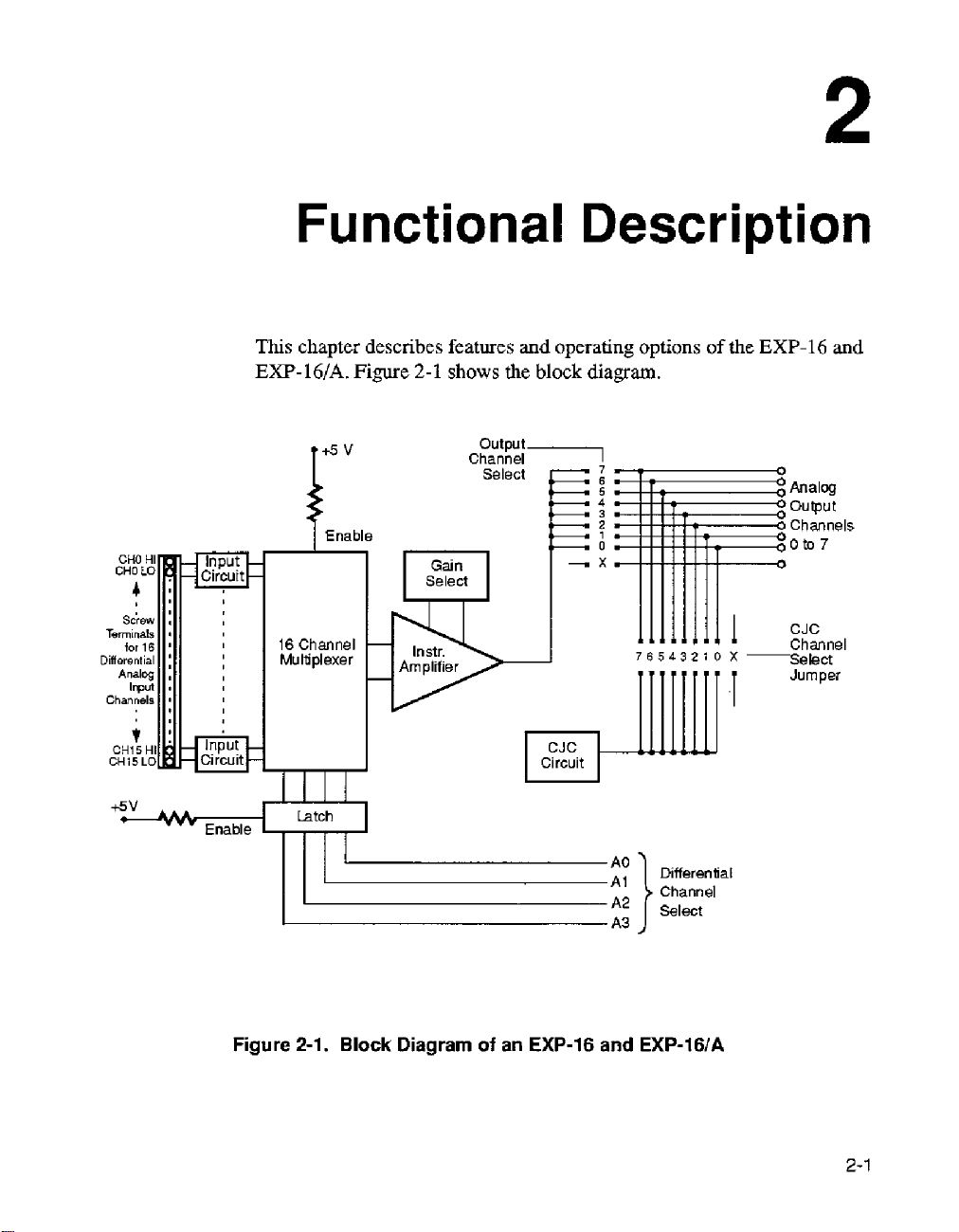
2
Functional
This
chapter
EXP-lWA.
describes
Figure
2-1
features
shows
and
the
Description
operating
block
options
diagram.
76543210
of
the
X-
EXP-16
and
Figure
2-1.
Block
Diagram
of
an
EXP-16
and
EXP-16IA
2-1
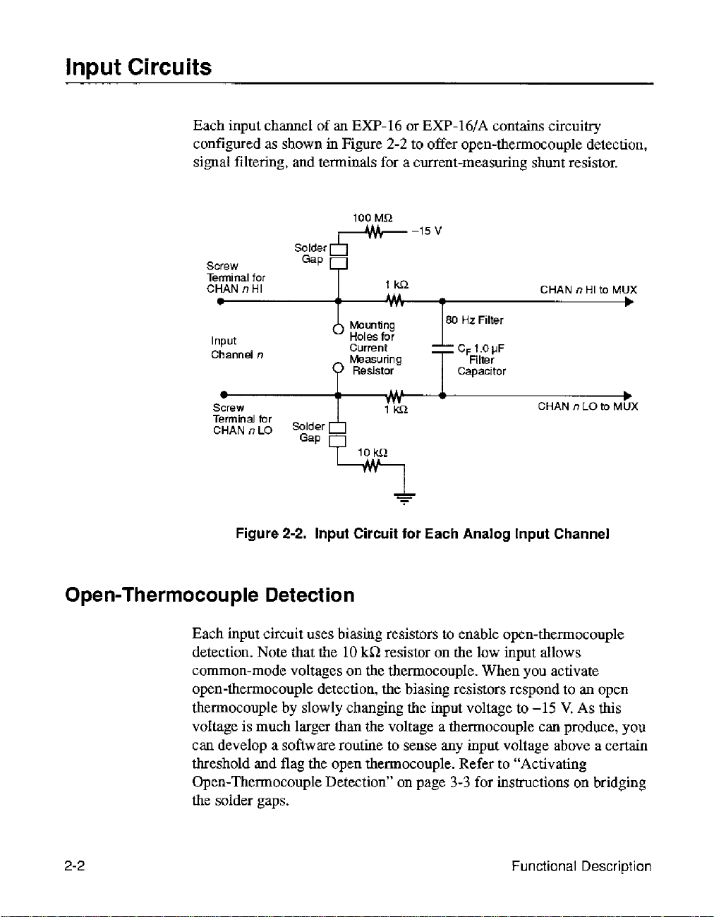
Input
Circuits
Each input channel
configured as shown
of
an
Em-16 or EXP-lGIA contains circuitry
in
Figure
signal filtering, and terminals
100
Screw
Tenninal
CHAN
for
nHI
-
Input Holes
Channel
Solder
Gap
0
I
T T
Mounting
n
Current
L
Screw
Terminal
CHAN
far
n
LO
Figure
sgzF
2-2.
Input Circuit
2-2
to offer open-thermocouple detection,
for
a current-measuring shunt resistor.
MR
-15
V
CHAN
80
HZ
Filter
for
wv
1
, ,--
111
Im
1
C,l.OpF
Filter
Capacitor
T
1
CHAN
-
for
Each
Analog
Input Channel
n
n
HI
LO
to
to
MUX
r
b
MUX
Open-Thermocouple
Each input circuit uses biasing resistors
detection. Note that the
common-mode voltages on
open-thermocouple detection,
thermocouple by slowly changing the
voltage
can develop a software routine to sense
threshold and flag the open thermocouple. Refer
Open-Thermocouple Detection”
the
2-2
is
much larger than the voltage a thermocouple can produce, you
solder
gaps.
Detection
10
to
enable open-thermocouple
ki2
resistor on
the
thermocoupIe. When you activate
the
biasing resistors respond to
on
input
page
the
low input allows
voltage
any
input
to
3-3
for
instructions
to
-15
voltage above a certain
“Activating
Functional
an
open
V.
As
this
on
bridging
Description
Signal Filtering
The
1.0
pF
filter capacitor and the two
filter for the input signal. If you
particular channel, you can remove the capacitor
that channel.
Current-Measuring Resistor
A
pair
of
mounting holes for a current-measuring
the
screw terminals
to
you
allow
size and power rating for the current
find it more convenient to place the resistor across the channel screw
terminals rather than in the mounting holes.
to solder
the
Multiplexer
An
Em-16
analog
be
to
TTL/CMOS-compatible address on the differential-channel-select lines,
shown
channel
or
input
sampled
in
Figure
1,2h
EXP-I6/A
channels
for
multiplexing
2-1.
selects channel
need
faster settling response for a
for
each channel. The holes
resistor into place.
you
multiplexes signals
into
one signal for the
is
selected
An address
of
Oh selects channel
2,
and
so
1
kn
resistors make
You
must determine the resistor
want
to
from
analog
by
a 4-bit
on.
up
an 80
to
disable the filter
resistor
are
measure.
is
located next
plated-through to
You
may also
the 16 differential
output.
Each channel
0,
lh
selects
Hz
for
Multiplexer
When
you
use
an EXP-16
con&ol the address
outputs are activated
and
guide
Refer to Appendix D for information
channels for software control.
Appendix C
with
or EXl-lG/A with a DAS-8 Series
by
for
DAS-8
DAS-8
digital
CALL
more information).
board,
outputs OP1
Mode 14 (see the DAS-8 user’s
on
the
numbering
to
OP4.
The
of
expansion
DAS-8
you
2-3

Instrumentation
The
multiplexer output feeds to
switch-selectable
also set the amplifier for other gains by installing a gain-adjustment
resistor
a high-performance device suitable for use with strain gauges and other
low-level transducers.
Amplifier
gains
of
(see
“Setting Gain” on page
0.5,
an
instrumentation amplifier with
1,
2,
10,
50,
100,
200, and
3-3).
The instrumentation amplifier
1000.
You
can
is
CJC
Circuit
Power
An
EXP-16
compensation circuitry that delivers
latter value corresponds
You
can connect the
output
circuit can support a data acquisition
measurements with types
If
you
An
EXP-
the
+5
converter module. The accessory
up the
Up Power” on page
or
EXP-l6/A.
or
EXP-l6/A
lines
using jumper
plan
to
use the
16 or
EXP-
V
alone from
+5
V
according to the
includes cold-junction sensing and
to
10 bits/”C with most 12-bit
CJC
output voltage
J3
(refer
to
B,
E,
J,
K,
CJC
circuit, refer
16/A
uses the
the
computer with the optional
+5
also
type
of
3-7
for information
0.0
V
at 0°C
and
24.4
mV/”C.
A/D
converters.
to
any
of the EXP-16 Series
Figure 2-1 on page
system
R,
has
DAS
performing temperature
S,
and
T
thermocouples.
to
the
cautionary note
V
and
+12
V
jumper arrangements for setting
board used. Refer
on
setting up power to
2-1).
from
the computer
PG-4OSA
The CJC
on
DC/DC
to
an
The
page
3-5.
“Setting
EXP-16
or
2-4
Functional
Description

Setup
Unwrapping
This chapter describes setup options for
this chapter before you attempt to install
and
After you remove the wrapped board from its outer shipping carton,
proceed as follows:
1.
2.
Inspecting Your
Your
Em-16
wrapper that must not be removed until you have discharged any
static electricity by either
-
If
you are equipped with a grounded wrist strap, you discharge
static electricity as soon as you hold the wrapped
-
If you are not equipped with a grounded wrist strap, discharge
static electricity by holding the wrapped
placing
chassis (your computer must be turned
Carefully unwrap your
(You may wish
or
EXF’-16/A
your
other hand firmly
EXP
to
store
is packaged at
of
the following methods:
from
the
wrapping material for future
the
Em-16
and
use your
and
EX€-lG/A.
Em.
Board
the
factory
EXP
on
a metal portion
off
its anti-static wrapping material.
in
an
anti-static
Em.
in one hand while
of
the computer
but grounded).
use.)
Read
3.
Inspect the board for signs
to return the board to
6-4).
4.
Check
to be sure
immediately.
5.
When
and hardware setup instructions.
Unwrapping and Inspecting
the
you
Your
of
damage.
the
factory
remaining contents
your
order is complete. Report any missing items,
are satisfied with the inspection, proceed with the software
Board
of
If
damage is apparent,
(see
“Technical Support”
your package against the packing list
arrange
on
page
3-1

Locating
components
Figure
EXP-16
3-
I
and
and
EXP-I6/A.
OUTPLT
mJ4
01
234587X
CJCwJ3
IR
Fl-
Figure
Figure
3-1.
3-2
show
the
Locations
locations
of
EXP-16
for
key
components
-
rE---fR0
piiiiiil
Key
Components
!
Gain
Switch
of
USER
the
3-2
1
52
dai
Switch
I
Figure
3-2.
Locations
of
EXP-16/A
Key
n
~~
Components
Setup

Act
i
va
t
i
n
g
0
pen
To
activate the open-thermocouple detection circuit
must bridge
EXP-16
solder gaps for the
the
screw terminals.
-T
her
m
o
co
u
p
I
e
Detect
the
two
solder gaps for that channel.
are
located under the board, beneath the screw terminals;
EXP-l6/A
are located on top
i o n
for
The
solder gaps for
of
the board, in front
a channel,
you
the
the
of
Setting
Caution:
soldering iron that
develops no more
To
avoid damaging the printed circuitry and components, use a
is
isolated,
than
40
grounded, operates on
W.
Gain
You
control gain on an
or
by
installing a resistor
configures the entire board for the selected gain.
The
gain switch is an 8-position
of
0.5,
1,2,
10,50,
as shown in Figure
ON
Em-16 orEXP-lG/A
in
special mounting holes.
DIP
100,200,
3-3.
and
1000.
t
I
12345678
q-N
0
less
either with the gain switch
Either
switch that
Positions
~0000
“Z88
offers settings
of
the switch are labeled
than
method
7
40
V,
for
and
gains
Figure
Activating Open-Thermocouple Detection
3-3.
Gain
Switch
(set for gain of
50)
3-3

In
applications calling
offerings, you
appropriate value
RU1
(on the
appropriate resistance value:
may
EXP-l6/A).
for
a gain other than the switch-selectable
set a gain of
on
the board space labeled
Use the folIowing calculation
your
choosing
USER
by
inserting a resistor of
(on
the
Em-16)
to
determine the
or
Resistance
The largest differential analog input
choosing a value of gain, or the output of
mix
you can
they all use
gains,
3-1
lists recommended gains for different thermocouple
Table
thermocouples
the
same
use a separate
3-1.
Recommended Gains
Thermocouple Maximum Maximum Suitable
I
J
(ohms)
of
gain.
For
Em-16
I
I
=
200,000
must
different types on one board so long as
mixed thermocouples requiring different
or
EX€-16/A
Output
43mV
/ (desired gain)
always be considered when
the
amplifier may saturate. Also
for each different gain. Table
for
Thermocouple Types
I
"C
I
760
I
I
types.
Gain
100
I
I
3-4
T
Note: Higher gains can be used for less than a full-scale span. Gains
based on a
45
V
output.
21
mV
400
200
are
Setup

Setting
the
Output Jumpers
The
Em-16
the selection of a
channel. The nine jumper positions include eight channel positions,
marked
positions
board (such as the
each jumper block.
and
0
to
7,
connect through external cabling to the inputs
EXP-16IA
CJC
and a blank position, marked
DAS-8).
contain two 9-position jumper blocks:
channel and J4 for the selection
The following subsections describe the use of
of
an
X.
The eight channel
of
an
J3
for
analog output
%channel
Selecting
Selecting
a
CJC Channel
If
CJC
is
required for a particular
of
J3
corresponding pins
choose for
output.
If
no cold-junction compensation is required, place the CJC jumper in
position
Caution:
the screw terminals, you
to place an
a
DAS
The eight jumper-selectable outputs of
to
you
(such
CJC
X
of
To ensure
EXP-
Board
connect
as
a
DAS-8
must
J3.
16
Channel
up
to eight
Series board) without the need for special cables.
for
be
different from
a
uniform
are
in
a covered enclosure.
of
DAS
board channel, jumper the
that channel. The
the
temperature between the CJC sensor and
advised to
these accessories to an 8-channel
use
an
DAS
board channel
channel you choose
an
EXF-l6/A with a cover or
ED-16
or
EXP-lGIA
DAS
for
allow
you
analog
board
Setting
the
Output
Note:
using
degraded.
Jumpers
You
for CJC, or the performance
cannot
use
the
same
channel for
of
your
analog
system will be seriously
output that you are
3-5

In
a
given system, each
of
a
3-2
details
board.
DAS
matches
channel
EXP-l6/A
Table
Series
Em-
16
or
EXP-l6/A
board.
channel selection configurations
the
Make
selected
sure
input
the
channel of
connects to a separate input
jumper
on
J4
the
for
of each
attached
an
attached
EXP-16
DAS
board.
DAS-8
or
Output Jumper
Location
I
I
I
I
As
Table 3-2 shows, the output channel
matches
Note:
board, you are advised to refer
board
Before connecting
user’s
the
1
3
5
7
input
channel of the
guide.
DAS
Channel Number
I
I
I
I
an
Em-16
to
Board
1
3
5
7
DAS
or
the
Call
Input Connector
Pin
Number
I
I
of
the
EXP-16
board.
EXE-l6/A
Mode descriptions in the
to
a
36
34
32
30
or
EXP-l6/A
DAS-8
JllJ2
I
I
I
I
Series
DAS
3-6
Setup

Setting
Up
Power
Using
Using
The following subsections describe the setup
arrangements
+5
V
and
To
perform
1.
2.
3.
4.
External
To
perform
for
theEXP-16
f12
V
External Supplies
use external
the
Set switch
Connect
EXP-16IA
Connect
maximum) to pin
Connect all power supply returns
EXP-16IA main
+5
V
use
an
the
+5
V
and
following procedure:
S
1
to EXT.
i-5
V
(30 mA
main
110
+12
V
(10
20
110
Only
external
+5
V
following procedure:
and
f12
V
supplies with the EXP-16
maximum)
connector.
mA maximum) to
of
the EXP-16
connector.
supply only with the EXP-16 and EXP-IG/A,
EXP-l6/A.
to
pin 29 of
pin
or
EXP-16IA main
to
pin
of
available power supply
and
EXP-l6/A,
the
EXP-16
1
and
-12
V
(10
1/0
11
of the EXP-16
or
or
mA
connector.
1.
Install a PG408A
PG-408A
2.
Set switch
3.
Connect the
EXP-l6/A
4.
Connect
1/0
connector.
Installing a PG-408A
The
PG-408A
pins protruding
space
on the EX€-16
Setting
Up
Figure
Power
3-2.
DC/DC
DC/DC Converter”
S
1
to
INT
@C/DC
+5
V
(250
main
I/O
connector.
th~
+5
V
return to pin 11
DC/DC
DC/DC
Converter
converter module
from
its bottom surface. The socket for this package is a
or
EXP-l6/A
converter module (refer to “Installing a
on
page
3-7).
on
some
boards).
mA
maximum)
marked
of
to pin
29
of
the
EX€-16
is
an
ecapsulated package
as
shown
or
in
the
ED-16
EXP-IG/A main
Figure
3-1
or
with
and
3-7

Pin 1 on the
module
of
the
when snapping the module onto the
shows
PG-408A
or a beveled corner
PG-408A
a diagram
with pin
of
the
is
indicated either by a beveled comer on the
on
the module label. Be
1
of
the socket (pin
pin 1 location.
EX€-16
sure
to
match pin
1 is
marked on the board)
or
EXP-16/A.
Figure
01
LJ
0 0
0
Board
socket
1
3-4
0
0
Setting
Setting
the
the
Figure
+5
V
Jumper
An Em-16 and
C-1800
an
S-1600
board. The
20
pin
how
Jumper
When an EXP-16
boards, you need no jumper
29
pin
plated-through holes labeled
Figure
must solder a
(also shown in Figure
3-4.
cable when connected to a DAS-S/SOO Series board or by way
cable when connected
+5
V
by way of a
to
set the EXP-16
for
an
EXP-16
is
hard-wired (on
3-1).
When
wire
0
0
0
Locating Pin 1 on
EXP-IGIA
power
C-1800
is
connected
receive
from
cable. The following two subsections explain
or
EXP-16IA jumpers for these situations,
for
the
EXP-16, see the trace between the
A
an
EXP-16
between the plated-through holes labeled B and
the
PG-408A
+5
V
power on pin
to a DAS-16/1600/1400/1200 Series
a
DASCON-1 board, however, arrives on
to
DAS-8/800/1200/1600/1400 Series
the
+5
V because the
and
+5
V,
which are
is
connected to a
and
Board
29
by way
+5
V
connection to
shown
shown in
DASCON-1
3-1).
0
0
0
Socket
board,
of
you
+5
a
of
V
Setup

Setting the
Jumper for
an
EXP-l6/A
(Jumper
J9)
Power
Notes
When
board, the jumper at
be on
When
EXT.
the
+5
the computer power supply.
input common-mode range
an
EXP-l6/A
(the factory default position,
an
EXP-16/A
the
two
used with a DAS-8 board,
and
f12 V power through the
If
a
PG-408A
S
1
to
INT (or
Note that the computer
(or
DC/DC)
i-5
V and
Also
note that the computer
switch
V
supply.
10
S1
mode,
mA
to
INT;
is
connected
J9
must
is connected to a
pins closest to switch
module
DC/DC).
is
installed
If
a
I/O
an
EXF-16
In
the
EXT
from
the
f12
the
f12
V
to
a DAS-8/800/1200/1600/1400
be
on
the
two pins
as
shown
DASCON-1
C-1800
PG-408A
bus has a limited output capability.
or
mode, the board draws up to
V
bus
of
f10
computer supply
in
S
1.
an
EXF-16
cable that connects
on
the
EXP-16
is
not installed,
EXP-l6/A
supplies. Be sure
supplies are
V,
you must install
farthest
Figure
board,
or
EXP-l6/A
draws up to
f12
is
inadequate for
3-2
on
page
the
jumper
or
EXP-l6/A,
set
you
do not overIoad
V.
If
you plan
a
from switch S 1
receives
the
switch
250
30
mA from
PG-408A
Series
3-2).
When
at
J9
must
+5
V
two boards.
set
switch
S 1 to
In
the
INT
mA
from
the
to
use
an
and
set
this
range.
Setting
Up
Power
3-9

Wiring
and Cabling
Using
the
This chapter describes
EXF-16s
Main
The
connectors:
board
Em-16
labeled
or
EXP-l6/As
I/O
Connectors
Em-16
J1
and
the
or
EXP-l6/A. The
J1
and
and EXP-l6/A
and
other
J2.
the
I/O
connectors
to
DAS boards and
contain
52.
Use either connector
for connection to
two
connectors
Figure
4-1
shows
LLGND-18
LLGND-17
LLGND-16
LLGND-I5
LLGND-14
LL GND; 13
LLGND-12
DCOM
19
-
11
A3-10
A2
-09
A1
-08
A0
-
07
06
05
04
03
02
+Vs-Ol
and
the
cabling
accessories.
or
two, parallel-wired main
for
an
STA-XX
are
37-pin,
the
pin assignments
connection
or
to
an
additional
D-type and are
for
wiring
1/0
a
DAS
J1
and
of
J2.
Using
the
Main
Figure
110
Connectors
4-1.
Pin Assignments
of
Main
UO
Connectors
J1
and
52
4-1

Connecting
Multiple
Use
C-1800
EXP-l6/As
system of up
or
up
to
compensation).
You
must select a different output channel on each
in a daisy
DAS
a
board input channel.
EXP-16s
cables to connect a daisy chain
with a
DAS
to
128
channels for standard voltage or current measurement
112
channels for thermocouple measurement (with cold-junction
chain. Set each board
or
EXP-I6/As
board. A daisy chain allows development of a
for
an
output channel that corresponds to
of
up to eight
EXP-16
EXP-16s
or
EXF'-16/A
or
Using
Series
Direct connection is also possible between an
an
the
seven single-ended inputs remaining, depending on whether cold-junction
compensation is used.
several
The folIowing subsections give specifics
or
EXP-16s
Boards
STA-XX
16
Figure
EXP-lG/As
or
screw terminal accessory. The
differential inputs of
EXP-
16s
4-2.
Daisy Chain
to various
EXP-I6/As
Figure
or
EXP- 16/As,
or
EXP-16
and an
EXP-1M
with
ED-16
STA-XX
an
EXP-16
4-2
of
a
STA-XX
DAS
boards.
outpot
Channel
or
EXP-16/A
illustrates a daisy chain
and
an
STA-XX.
1
EXP-16
or
EXP-lWA
DAS
Board
(all cables
with
EXP-16
are
C-1800)
on
connecting multiple
DAS-16/1600/1400/1200
or
EXP-l6/A
can accommodate
and
still have
of
a DAS board,
or
and
six
STA-XX
EXP-lG/A
ED-16s
or
4-2
You
can add up to eight
of
a
DAS-16/1600/1400/1200
Digital
outputs
EXE-16
it exercises the digital outputs
OPO
or
EXa-16/A.
EXP-16
to
OP3
drive the multiplexer address Iines
Check your application
or
EXP-l6/As
Series
while
board
to
gain up
software
performing
to
A/D
the
analog
conversions.
input
to
128
channels.
of
to
determine how
Wiring
and
section
the
Cabling

Use
an
S-1600 adapter cable to connect the first
the DAS-16/1600/1400/1200 Series board. Use
or
more EXP-lGs
EXP-lG/As. Refer to Figure 4-3
3-foot S-1600 cable.
EXP-16
C-I800
for
a
or EXP-I6/A
cables to add
diagram
of
to
the
Connecting
Multiple
Figure
When connecting EXP-16
Series
boards,
set switch
should
be
as shown in Figure
additional
you
S1
to
INT
on
the
two
EXF-16s
must use
or
DC/DC.
pins farthest
3-2.
Figure 4-4 is a diagram showing the
or
EXP-lG/As.
DAS-16/1600/1400/X200
Figure 4-4.
EXP-I
with
6s
A
Daisy Chain
an
STA-XX
or
EXP-1
and
6/As
4-3. S-1600
or
EXP-l6/As to
the
optional PG-408A DCDC converters
On
Series
boards
of
a
up
to
Cabte
Wiring
the
DAS-l6/1600/1400/1200
the EXP-l6/A, the
from
switch
You
S
must set
I.
(in
the
jumper
its
default
for single-ended
DAS-16/1600/1400/1200 Series
Eight EXP-16s
or
EXP-l6/As
use
inputs.
and
at
J9
position),
of
board
4-3

Note that in Figure 4-4,
be
wired to the
STA-XX.
the
analog outputs of additional
DAS
boards can
Using
Board
When you connect
DAS-16/1600/1400/1200
Em-16
EXP-16
However, you can partition
inputs (that are sampled directly
indirect inputs (sampled through the
EXP-l6/A
such
All
and each
different gain.
different channel functions,
differential).
EXP-16s
You
inputs of a
multiplexes
DAS-XPGNpCDAS-XPGA
for a total of
are set
or
scan
an
EXP-16
channels in the fast
multiplexer address lines through the
is best suited to handling high-gain, low-rate-of-change inputs
as
thermocouples, pressure transducers, and
analog
or
5,
input channel connections are made
EXP-16
EXP-l6/As
can add
DAS-XPGA/pCDAS-8PGA. An
by
digital outputs
increments the multiplexer address with Mode 14,
of
Mode
or
EXP-l6/A
In
this way, a system can be configured with a variety of
with
EXP-
16s
or
16
inputs into a single output channel. Therefore, a single
128
input channels.
4
or
5 on the next set
or
EXP-lG/A
Series board, you cannot sample the added
DMA
sampling mode because you drive the
your
channels into some high-speed direct
by
the
EXP-
(group
gains,
and input modes (single-ended and
a
DAS-8PGAlpCDAS-8PGA
EXP-l6/As
supports
OF1
to
The
OP4,
of
to any
up
Em-16
to
a
digital
DAS
board) and some low-speed
16
or
Em-
through
of
16
channels) can operate at a
or
dl
EXP-16
to
eight
EXP-16s
multiplexer address lines
so
that a typical scan uses Mode
multiplexer channels, and
output
16/A).
so
on.
of
the eight
or
port.
screw connectors,
EXP-l6/A
or
and
repeats the
The
EXP-
16
analog
EXP-l6/As
4
so
on.
4-4
When
using
the
DAS-SPGA/pCDAS-SPGA
EXP-l6/As,
inputs
necessitated by the wiring configuration of the
addition, you must
correspond to
or
EXP-
jumper at
default position), as shown in Figure
using
16/A
J9
you
must configure channels
switch
must
S2
(on
the
DAS
board); this requirement is
also
set the
the
analog output and CJC jumper settings
for single-ended configuration. On the
be
on the two
DAS-XPGA/pCDAS-SPGA
pins
farthest
3-2.
with EXP-16s
1,2,3,
and
EXP-16
from
or
5
as
single-ended
or
EXP-l6/A.
channels that
of
each
EXP-
EXP-l6/A,
switch
Wiring and Cabling
S
1
(in its
the
In
16

An
Em-16 or EXP-l6/A
connectors similar
cable should be provided for each EXP-16
channel connections are made through screw terminals, and each EXP- 16
or
EXP-lG/A (group
this way, a system can be configured with a variety of different channel
functions, gains, and input modes (single-ended and differential).
Use
a C-1800 cable for connecting aDAS board to
EXP-16IA and
The EXP-16s
measured are near f10
to
for
connecting a daisy chain
or
EXP-l6/As do not require a PG408A unless signals to be
is
designed to connect with flat cable and
those used for the DAS-8PGA/pCDAS-8PGA. One
or EXP-I6/A. All analog input
of
16
channels) can operate at a different gain. In
an
V.
EX€-16
of
EXP-16s or EXP-16/As.
or
Using
Using
EXP-16s
Use
DAS-8AO/LT Series board. These DAS boards
connected EXF-16
converter module and that switch
EXP-l6/A, the jumper at
S1 (in
EXP-16s
Use only
DASCON-1 board. You should be aware, however, that
can properly connect only the first three channels
the
the input channels to
The DASCON-1 requires
used with a PG408A
or
To
follows:
and
EXP-I6/As
a
C-1800 cable to connect
or
EXP-16/A to be used with a PG408A
its
default position), as shown in Figure
and
EXP-I6/As
a
C-1800
EXP-16s
cable to connect an EXF-16
or
EXP-16/As and that you should connect
analog
DC/'DC converter and
DCDC.
use
a
DASCON-1 with
with
J9
DAS-8AO/LT
an
ED-I6
S
1
be set for JNT
must
be
on the two
or
EXP-I6/A
also
pins
Boards
to a
require each
DCDC
or
DCDC.
farthest
from
3-2.
with
a
DASCON-1
Board
or
EXF-16IA
of
the DASCON-1 and
to
a
C-1800 cable
the
low side
ground.
each
connected EXP-16
that
an
EXP-16, you must modify the EXP-16 as
or
EXP-lWA to be
switch S 1 be set
On
a
for
an
switch
of
INT
Connecting
Multiple
1.
Cut the etch between the point
+5
marked
2.
Add a jumper between the point marked B and the
EXP-16s
V.
or
EXP-16iAs
on
the board marked A and the point
point
marked
+5
V.
4-5

To use
the two
a
DASCON-1
pins
closest
with an
to
switch
EXP-l6/A,
S1.
you must place the
J9
jumper on
Avoiding Ground
An
EXP-16 or
input. While differential inputs are better
many applications, they require more
ground loops
offered
to
If you
is
already grounded,
&L
GND)
correct connections for
Loops
EXP-l6/A
and
other undesirable effects. The following rules are
help you avoid
are
driving
to
Figure
an
its channel’s low
4-5.
Connecting a Grounded Signal
provides
the
EX€-16
do
not connect the
16
pitfalls
or
input
a
grounded
channels of differential
than
single-ended
care
in their configuration
of
configuring
EXP-l6/A
EXP‘s
(LO).
these
horn
a signal source that
low-level
Figure
4-5
source.
Source
analog
inputs
to
for
avoid
inputs:
ground
illustrates the
to
LL
GND
at
he
4-6
If
you are connecting
source (such
must be connected
at
wire
as
a
thermocouple), the low-level ground
to
the
appropriate screw terminals. Figure
correct connections for
+
Signal
Source
,-
Es
Figure
4-6.
Connecting a Floating Signal Source
an
Em-16
or
EXP-
I.
6/A
the channel’s low input
a floating source.
to a floating
(LL
GND)
by
instdling a jumper
4-6
illustrates the
Wiring
and
signal
Cabting

Cali
bration
Equipment
This chapter describes calibration requirements for
EXP-lG/A.
Each
EXP-16
adjustment prior to installation. However, periodic calibration may be
required to compensate for component aging, environmental changes, and
so
on.
The
can be one year or more.
the calibration period can
Req
u
You
must have
EXP-
16JA
A
4
A
voltage calibrator (or a stable noise-free
be
used with the digital voltmeter)
If
the
or other temperature-measuring device accurate to
and
EXF'-16/A
calibration
period
is factory cdibrated; it requires no further
in
a
clean, temperature-stable environment
In a dusty or varying-temperature environment,
be
as littIe
as
three
irernents
the
following equipment
1/2
digit digital voltmeter
CJC
circuitry is to be calibrated, you need a digital thermometer
to
calibrate
your
months.
an
DC
voltage source
Em-
EXP-16
+2O
C
16
or
or
that
can
Equipment Requirements
5-
1

Instrumentation
To
calibrate the instrumentation amplifier of
perform
1.
Connect power to the EXP-16 Series board (refer to “Setting the
Output Jumpers” on page
Wire
2.
GND terminal to
Amplifier
the
following steps:
the
CH15
HI
short
Calibration
3-5
for
instructions).
terminal
to
the
CH15
them together.
your
Em-16
LO
terminal and to the
or
ED-
16/A,
LL
Select channel 15 either
3.
to
+5
V
or,
if connected to a DAS
outputs high with your application software.
Connect the digital multimeter
4.
pins
on
the
upper side
shown in Figure
Set the gain switch to
5.
6.
Adjust the zero
the
multimeter reads 0 VDC.
7.
Set the
8.
Adjust the
until the multimeter reads
9.
One
step 2 of this procedure; select a channel using the channel-select bits,
and make sure the channel is at
10.
Set the gain switch
11.
Connect the positive terminal
and
Set
12.
V;
to
gain
at
a time, connect each
the
negative terminal to CH15
the
input voltage
for example,
5
V I 10
5-1
in
switch
zero
out potentiometer
if
=
0.5
V.
by
tying
of
the
output channel jumper connector
and
Figure
1000.
potentiometer
to
0.5.
0
VDC.
of
the
to
the desired value.
of
so
that
the
you
are
to
run
the channel-select pins (pins 7 to
board,
by
setting all
from
LL
GND
to one
5-2,
below.
(Em-16:
(Em-16:
other input channels
0
VDC
the voItage calibrator to
LO
input voltage times
at
a
R75;
fl
mV.
and to LL
gain
of
EXl-16A:
R76; EXP-16A:
10,
four
of
the
R49)
(0
to
CH15
GND.
the
gain equals
set the input voltage
digital
jumper
(541,
until
R34)
14)
as
HI
10)
as
in
+5
5-2
Adjust the
13.
+5.000
+1
gain
potentiometer (EXP-16: R74; EXP-16A:
mV
output reading.
R50)
Cali
for a
brat
ion

J2
r-----_l
1
PG408A
1
(if
L-----,
used)
I
I
&in
Switch
Figure
Figure
5-1.
5-2.
Locations
Locations
of
EXP-16
of
EXP-lG/A
Calibration Components
Calibration Components
Instrumentation
Amplifier
Calibration
5-3

CJC
Circuit Calibration
1.
Connect the multimeter
the upper side
2.
Monitor
the
temperature in the vicinity
from
LL
GND to one
of
the output channel jumper (33).
of
of
the jumper
CR2,
the CJC sensor.
pins
on
3. Adjust the
obtain a multimeter reading
digital thermometer reads 17.0
until the multimeter reads
CJC
ADJ
potentiometer (Em-16: R77; Em-16A: R33) to
of 24.4
"C,
0.0244
mV
per "C; for example, if
adjust
the
CJC
x
17.0
or
0.4148
the
ADJ potentiometer
V).
5-4
Calibration

This
chapter guides you
an
using
EXP-16
Troubles
in
resolving problems
or
EXP-l6/A.
hooting
with
measurement systems
Problem
Is0
lation
If you suspect a problem with faulty hardware
try
to
isolate
the
problem
the
components
EXP-l6/A.
I
;
HOSTPC
Figure
Measurement systems that use
configuration
isolation
you
procedure
can
use to isolate a system problem
in
6-1.
and
complexity,
to a major
a simple measurement system using
EXP-16
that applies to
or
EXP-lG/A
the
EXP-16
so
it
all
or
with
cabling
system component. Figure
an
Em-16
EXP-16
or
0
EXP-IWA
is
not
systems.
System
or
possible
are
as
Components
EXP-l6/A
to
Two
follows:
vary
provide one problem
general techniques
and
6-1
in
wiring,
shows
or
Remove a suspected component
separately.
from
the
system and test
it
6-1

An
example
Em-16
connector
example
conductors
or
is
of
this
kind
of
test
is
checking the
EXP-l6/A
and
observing the outputs at the output connector. Another
using
.
by applying known input signals at
an
ohmmeter to test the continuity
signal
of
path through
the
wiring
input
or
cable
an
Common
~
Symptom
Replace a suspected component
you have another
DAS
board
works,
then
Problems
Table
6-1
measurement systems using the
solve
the
6-4.
Table
6-1. Problems
I
Possible
and
lists symptoms and suggested solutions for problems with
problem with
DAS
in
a malfunctioning system.
you have isolated
Solutions
this
Cause
with
one that
board that is functional,
the
problem to
EXP-16
table,
refer
and Suggested Solutions
or
to
“Technical
~ Suggestions
works.
use
If
the malfunctioning system
the
original DAS board.
EXP-lWA.
Support”
For example, if
it
to
replace the
If
you
cannot
on
page
I
6-2
Troubleshooting

Table
6-1.
Problems
and
Suggested
Solutions
(cont.)
Symptom
Mermittent operation
Possible
Vibrations or loose connections
Overheating
Electrical
Inadequate power
Cause
noise
Suggestions
Cushion source
tighten
connections.
Check for
and
try
to position the
EXP-lG/A
Make sure
correct cable to connect the
board
to
EXP-l6/A. Make
cover
is
installed. Re-route
cable away
emissions,
monitors.
Make sue
rating
is
current demand. Make sure the
wires
or
Refer
to
of
vibration and
external
away from them.
you
the
are
EXP-16
heat sources
EXP-16
using
or
sure
from
likely sources
such
as video
the power supply
sufficient
cable
Chapter
to handle the
are
not
too
4.
the
the
DAS
PC
the
long.
or
of
[nvalid data
Bad input connections
EIectrical noise
Check cabling or wiring
sensors
inputs.
Use shielded input
sure
Re-route the
likely sources
as
to
EXF-16
the
PC
cover is installed.
wiring
of
video monitors.
or
EXP-l6/A
wiring.
away
emissions, such
from
Make
from
6-3

j
Symptom
Table
6-1,
Problems and Suggested Solutions
I
Possible
Cause
I
Suggestions
(cont.)
I
Technical
6-4
Support
Troubleshooting

An
applications engineer will help
board problem over the teiephone.
following information:
you
try
To
save time,
to
diagnose
be
md
ready
resolve
to
furnish
your
the
EXP-16
or
EXP-l6/A
configuration
DAS
board
configuration
Computer
Operating System
Model
Serial
#
Revision
Number
Number
Model
Serial
Revision
Base address
Interrupt
Number
Input
Mode
DMA
Manufacturer
CPU
Clock
KB
Video
BIOS
DOS
Windows
Windows
code
of
of
#
code
level
of
(S.E.
(uni.
channel(s)
type
speed
of
RAM
system
type
version
version
mode
channels
Ew-16~.
setting
setting
channels
or
Diff.)
or
bip.)
(MHz)
Software package
Compiler
(if applicable)
Accessories
Name
Serial
#
Version
Invoice/Order
Language
Manufacturer
Version
#
6-5

If
a
teiephone resolution is not possible,
issue you a Return
return the equipment.
documentation regarding
Material Authorization
Please
reference the
the
equipment and on the outside of
shipping container.
When
returning equipment
for
information:
Your
name,
A
description
The
RMA
address,
of
the
and
problem
number on the
telephone number.
outside ofthe package.
repair,
please include the following
or
its symptoms.
the
applications engineer
@MA)
RMA
number and
number in
any
the
ask
will
you to
Note:
you
Repackage
If
you
are
submitting
must hish the invoice number
the
equipment. Use its original anti-static wrapping, if
possible.
your
equipment
and
date
for
repair
of
purchase.
under
warranty,
6-6
Troubleshooting

The
following
Specifications
tables contain specifications
for
EXP-16
and
EXP-I
A
6/A.
1
Feature
1
Temperature
1
Common
I
Analog
output
Table
Feature
1
Output
coefficient
mode
range
current
A-2.
at
Table
0.0
A-I.
Analog Data
I
Specification
1
5
ppm
typical;
1
k1O
V
maximum
I
20
mA
maximum
Cold-Junction Compensation
I
Specification
c
I
0.0
v
15
ppm
maximum
1
I
1
I
I
I
A-1

Table
A-3.
Gain
Relationships
Gain
1
100
1
Notes
I
Settling
standard
I
Feature
1
+12
Maximum
input Offset
Voltage
1
times were obtained without
input
V
current
Drift
2pV/T
filter
Table
Common instrumentation
Mode
Rejection Nonlinearity 1 Settling Time'
I
125dB
(two
1
kn
resistors
A-4.
I
Specification
1
8
mA
typical;
Amplifier
1
0.005
0.015
an
input
filter.
and
a
1
pF
Power Requirements
I0
mA
maximum
I
Settling
capacitor)
(without
times
are
15
ps
12
ps
obtained with
greater.
I
PG-408A)
I
A-2
Table
A-5.
]
Feature
j
Storage temperature
Environmental Specifications
I
Specification
1-40
to
100
range
OC
I
I
Specifications

I
Feature
I
Weidt
I
screw
Table
terminal
wire
A-6.
sizes
Physical
I
Specification
I
0.5
I
12
Specifications
lb
to
22
AWG
I
I
A-3

Connector
An
EX€-16
connectors.
connector
is
normally
types
shown
or
EXF-l6/A
While
(Jl)
cabled
of
accessory. Pin assignments
in
Figure
both
is
normally cabIed
to
B-1.
Pin
Assignments
contains two, parallel-wired, 37-pin,
connectors carry the
to
the
an
additional
EXP-16
for
main
DAS
board,
or
EXP-
the main
I/O
I/O
signals,
and
the second
16/A
or
to
connectors
male
the
first
another
are
D
(J2)
Figure
A3-
A2 - 09
A1
A0
+vs
14
-
16
-
12
10
-08
-
07
06
05
04
03
02
-
01
LL GND - 18
LLGND-17
LL GND
LLGND-15
LLGND-14
LL GND-- 13
LL GND
DCOM - 11
B-1.
Pin Assignments for Main
I/O
Connectors
J1
and
52

Operating
This appendix contains miscellaneous additional material on the
operation
of
an
EXP-16
or
EXP-l6/A
with
DAS-8
Notes
Calls.
Input
Channel Selection with
Each channel
TTL/CMOS-compatibIe address on the differential-channel-select lines,
shown in Figure
channel
When
you use
address with the
outputs are activated
for
guide
Upon
execution of
DAS-8
the selected channel. To read other channels, use the Mode
again to select a new input channel.
Input channels
BASICfor..
steps required
A/D
(in
the
DAS-8
set, the
user’s guide for detaiIs.
to
be sampled
2-1.
1,
2h
selects channel
an
EXP-16
DAS-8
a description
the
remain fixed;
of
an
.next
loop.
to
scan
Mode
4),
and
must be ready
DAS-8
binary code
An
address of Oh selects channel 0,
or
digital outputs
by
DAS-8 CALL
of CALL
Mode
any
subsequent
EXP-1.6
The following example shows the programming
the channels
store the data in
to
must
DAS-8
for
multiplexing
2,
and
so
EXP-16/A
modes).
14
CaL, the
or
EXP-l6/A
of
run;
that is, the
be loaded,
Calls
on.
with a
OPl
Mode
DAS-8
can
an
EXP-16
an
may called
and
is
selected by a 4-bit
lh
selects
DAS-8,
to
OP4.
14
(see the
OPO
to
routines are performed
be scanned using a simple
DAS-8
so
you
control the
These
DAS-8
DAS-8
OP3
outputs
or
EXP-lWA,
DIO%.
base address must be
on. Refer to the
14
Note
user’s
of
CALL
read the
the
on
that
DAS-8
Input
Channel
Selection
with
DAS-8
Calls
c-1

XXXlO
xxx2
0
xxx3
0
xxx4
0
xxx5
0
xxx6
0
xxx7
0
xxx8
0
xxx9
0
CALL
FOR
I
MDS
=
CALL
MD%
=
CALL
NEXT
DAS*
DAS8
DAS8
I
(MD%,
=
0
TO
14:
OPZ
(MDC,
4:
(MD%,
The
data
channel
2
channels are
loops.
LT%(O),
15
=
I
OPS,
DIO%(I),
from
channel
in
DI0%(2),
to
be used, they can
FLAG%)
FLAGS)
FLAG%)
0
is
in
and
Array
DIO%,
so
on. If more than
be
scanned simply by nestingfor.
'Sets
'channel.
'This
'to
'channel selected
'EXP-16
'Sets up channel scan
'routine.
'Sets
'channel
'Sets
'Set
'Perform
'Return
DAS-8
must be
the
EXP-16
jumpers.
up
MODE
1.
channel.
MODE
4.
conversion.
to
channel 1 is
one
of
the
input
set
equal
out
by
14,
next
scan.
in
DIO%(I),
DAS-8 input
...
the
next
Software
Support
The outputs
strain-gage bridges
amplification before their application
(analog-to-digitai) inputs (including
for
Low-Level Devices
of
low-level transducers, such
(load
cells,
pressure
the
and
to
the
DAS-8).
as
Em-lG/A incorporates an instrumentation amplifier
amplification
of
thermocouples. The
requirements
and
includes circuitry
Em-16
for
DC output transducers.
or EXP-lG/A can handle most interface
allowing
thermocouples
and
force transducers), require
high
level
of
many
AD
An
EXP-16
that
or
provides stable
cold-junction compensation
c-2
Operating
Notes

Included in
Themolub.
Em-16
intended to interface directly with
linearization routines are adaptable to perform linearization on any set
thermocouple data that
Thermolab programs include the following:
0
ONE-EXP.BAS
with a
ED-16
This diskette contains
or
EXP-l6/A
or
EXP-lG/A
with a
can
-
A
program for using one
DAS-8
software package is a diskette labelled
BASIC
DAS-8.
the
be brought
programs illustrating use
Though this package of programs is
DAS-8,
into
the thermocouple
the
BASIC
ED-
workspace.
16
or
EXP-l6/A
of
an
of
MANY-EXP.BAS
0
EXP-l6/As
EXP-J
0
J.BAS
Before running these routines, copy
Em-I6
from
thermocouple subroutines
your own
to
subroutines are commented
software diskette. You may
your
allow merging for use with different thermocouple types. The
GOSUB’d
look-up array (that may
section of each subroutine performs a linear interpolation.
both fast
thermocouples. To avoid error messages, data should be bounded to
physicafly realizable minimum/rnaximum values before entering the
subroutines.
The examples
for
programming
use
and
with
with a
to
R
to
R.BAS
DOS
diskette to
BASIC
in the initialization section
accurate over
are
a
DAS-8,
your
-
A
program
for
using three
EXP-16s
or
DAS-8
-
Examples
-
programs. Each subroutine has different line numbering
just one way
own applications.
of
using thermocouples
Subroutines for thermocouple linearization
the
EXP-16
are
in
and
require a
DAS-8.ADR
also
wish to copy
software diskette. The
ASCII
consist of a data section that should be
to facilitate merging them into
of
your
few
seconds
and
DAS8.BLN
BASICA.COM
program. This loads a
of
load time). The second
This
the
full
operating temperature range of the
of
programming
but they can serve as a starting point
an
EXP-16
or
EXP-l6/A
for
onto the
method is
Software
Support
for
Low-Level Devices
c-3

Channel
This
appendix describes the assignment
board and all attached
Panel utility.
Numbers for Software
of
EXP-16s
channel numbers
for
use in software such
for
as the
a
DAS
Control
Channel
Numbering
DAS-8/800
0
through
16-channel EXP-16 Series
of
available channels
consecutive
beginning
channels associated
Table
for
Series
7.
If
you
analog
with
D-1
.
DAS-81800
Onboard Channel
I
I
I
8-Channel
boards
require additional channels,
onboard channel
Channels in Maximum
contain
expansion
to
128.
Expansion accessories are assigned
input channels
with
each expansion accessory.
Series
0
2
4
eight
accessories
of
the
0.
Table
I
I
I
DAS
analog
EXP-16
Boards
input channels,
you
can use
to
increase the number
DAS-S/SOO
D-1
lists the software (logical)
EXP-8/800
and
EXP-lfYA
Software (Logical)
Channels
0
to
15
32
to
41
64
to
79
up
Series board,
Configuration
numbered
to
eight
to
I
I
I
Channel
Numbering
for
&Channel
I
DAS
6
Boards
I
96
to
111
I
D-I

Figure
remaining onboard channels on
single-ended mode.
to
D-1
illustrates
the
physical channels on the Em-16
the
use of three EXP-16s or EXP-l6/As
In
software such as the Control
a
DAS-8/800 Series board configured
input channel 0 as logical channels 0 to
EXP-16
channels 16 to
attached to analog input channel
to the remaining 13 onboard
through
or
EXP-16/A
31,
7)
in
software as logical channels
attached
and the physical channels
analog
~
DAS-8/800
Series
Board
to
analog input channel
2
as logical channels
input channels (physical channels
chm
0t015
0-
1-
2
3’
4
5
>channels
6
7-
Panel
or
EXP-l6/A attached to
15,
the physical channels
1
on
the
EXP-16
32
48
through 52.
ne
Is
EXP-16
channels
16
to
31
EXP-16
Onboard
48to52
I,
channels
32
and
utility,
as
logical
or
EXP-l6/A
to
47.
to
47
the five
you
refer
analog
on
You
refer
for
the
3
Figure
You
can
0-1.
perform
multiple channels.
Channel Numbering
DAS-16/1600/1400/1200 Series boards are switch-configurable
16
single-ended analog input channels (numbered
differential analog input channels (numbered
more than the
EXP-16s
256.
D-2
or
EXP-l6/As
Analog Input Channel
an
analog input operation
for
16-Channel
16
single-ended onboard channels, you can use up
to
increase
Numbering
on
a
DAS
0
the
number of
Channel Numbers
for Software Control
single
channel or
Boards
0
through
through
7).
available
on
for
15)
or
If
you require
to
channels
for
Software
either
eight
16
to

EXP-16s
channels, beginning with onboard
(or
or
EXP-l6/As
logical) channels associated
are assigned to
with
consecutive
channel
each
0.
Tabfe
EXP-16
onboard analog input
D-2
lists
the
software
or
EXP-l6/A.
Table
D-2.
Channels in Maximum
Onboard Channel
I
I
I
I
I
I
0
2
4
6
8
10
EXP-16
EXP-16
Software (Logical)
I
I
I
I
I
I
Series Configuration
and
Channels
Oto
32
to
64
to
96
to
128
to
160
to
EXP-16/A
15
47
79
111
143
175
I
I
I
I
I
I
Channel
Numbering
I
I
Figure
remaining onboard channels
configured
utility,
attached
physical
for
D-2
illustrates
for
you
refer
to
analog
channels
16-Channel
12
14
the
use
single-ended mode.
to
?.he
physical channels
input
channel 0
on
the
EXP-16
DAS
Boards
I
I
of
three
Em-16~
on
a
DAS-16/1600/1400/1200
In
software
as
logical channels 0 to
or
EXP-16/A
on
192
224 to
or
such
the
EX€-16
attached
to
207
239
EXF-lG/As
Series board
as
the
Control
or
EXP-l6/A
15,
to
analog input
I
I
and
the
the
13
Panel
D-3

channel 1
EXP-16
channels
as
logical
or
EXP-I6/A
32
to
47.
channels
attached
You
refer
channels (physical channels
60.
EXP-16
channels
010
to
3
16
to
the
to
15
to
31,
and
analog
remaining
15)
in
software
EXP-16
channels
16
to
the
input
31
physical
channel
13
onboard
as
channels
2
as
logical
analog input
logical channels 48 to
on
the
DAS-16/16c10/1400/1200
Series
Board
Figure
D-2.
15
t]
Analog
On
board
channels
Input
Channels
EXP-16
channels
32
to
47
D-4
Channel
Numbers
for
Software

Index
connectors, main
current-measuring resistor
I/O
4-1
2-3
A
accessory
C-1800
PG-408A
PG-408A
S-1600
amplifier, instrumentation
anti-static wrapper
applications engineer
applications
avoiding ground loops
cable
1-2
2-4
DCDC
cable
converter
1-2
2-4
3-1
6-5
for
EXP-16 Series boards
4-6
B
block
diagram
2-1
C
C-1800
calibration requirements
Call
channels, logical
channel-select Lines
CJC
common problems and solutions
component
components, calibration
connecting multipIe
connecting
cable
1-2
5-
1
Mode
3-6
D-3
2-3
circuit
2-4
locations
3-2
5-3
boards
to
DAS-
16/l600/1400
DAS-sAOLT
DAS-gPGA/PCDAS-8PGA
DASCON-
STA-XX
Boards
1
Board
accessory
4-2
Series
4-5
4-5
4-2
boards
1-2
6-2
4-4
1-2
4-3
D
daisy chain
da5-8
DCDC
detection, open-thennocouple
diagram,
of
EXP-16
CALL
modes
converter
block
2-1
3-7
Series
C-
1
E
equipment, calibration
expansion accessories
external
power supplies,
5-1
D-1
using
F
factory calibration
features
filter, input signal
of
EXP-16
note
5-1
Series boards
2-3
G
gain
amplifier
for
resistor
setting
ground
grounded
2-4
thermocouple
type
3-4
3-3
loops, avoiding
wrist
strap
3-1
3-4
4-6
boards
2-2
3-7
1-1
4-2
x-1

I
R
input channel selection
instrumentation amplifier
instrumentation amplifier, calibration 5-2
C-
1
2-4
J
J9
jumper
jumper blocks,
(EXP-16A
9-pin
only)
3-5
3-9
L
logical channels
D-3
M
multiplexer 2-3
resistor
current-measuring
gain-adjustment 2-4,3-4
RMA
number
6-6
5
5-1600
selecting
setting
software
STA-XX
switch, gain
cable 1-2,4-3
CJC
channel
CJC output channel
DAS
board channel
J9
jumper position
3-5
4-6
switch
S1
support
accessory
3-7, 4-3,
C-2
4-2
3-3
2-3
3-5
3-5
3-9,4-3,4-4,4-5,
4-5
0
open-thermocouple detection
activation
circuit description 2-2
output
jumper
3-3
settings
3-5
P
PG-408A
accessory
instaIlation
module
pin assignments, main
problem
programming example
x-2
1-2
2-4
isolation
3-7
6-
1
I/O
C-
1
connectors B-
1
T
technical support, obtaining
thermocouple linearization routines
thermocouple types
Thermolab diskette
2-4
C-3
6-4
U
using
an
S-1600
cable
4-3
W
wrapper, anti-static
3-
1
C-3
Index

Specifications are subject to change without notice.
All Keithley trademarks and trade names are the property of Keithley Instruments, Inc. All other trademarks and
trade names are the property of their respective companies.
Keithley Instruments, Inc. 28775 Aurora Road • Cleveland, Ohio 44139 • 440-248-0400 • Fax: 440-248-6168
1-888-KEITHLEY (534-8453) • www.keithley.com
Sales Offices: BELGIUM: Bergensesteenweg 709 • B-1600 Sint-Pieters-Leeuw • 02-363 00 40 • Fax: 02/363 00 64
CHINA:
Yuan Chen Xin Building, Room 705 • 12 Yumin Road, Dewai, Madian • Beijing 100029 • 8610-6202-2886 • Fax: 8610-6202-2892
FINLAND: Tietäjäntie 2 • 02130 Espoo • Phone: 09-54 75 08 10 • Fax: 09-25 10 51 00
FRANCE: 3, allée des Garays • 91127 Palaiseau Cédex • 01-64 53 20 20 • Fax: 01-60 11 77 26
GERMANY: Landsberger Strasse 65 • 82110 Germering • 089/84 93 07-40 • Fax: 089/84 93 07-34
GREAT BRITAIN: Unit 2 Commerce Park, Brunel Road • Theale • Berkshire RG7 4AB • 0118 929 7500 • Fax: 0118 929 7519
INDIA: Flat 2B, Willocrissa • 14, Rest House Crescent • Bangalore 560 001 • 91-80-509-1320/21 • Fax: 91-80-509-1322
ITALY: Viale San Gimignano, 38 • 20146 Milano • 02-48 39 16 01 • Fax: 02-48 30 22 74
JAPAN:
New Pier Takeshiba North Tower 13F • 11-1, Kaigan 1-chome • Minato-ku, Tokyo 105-0022 • 81-3-5733-7555 • Fax: 81-3-5733-7556
KOREA: 2FL., URI Building • 2-14 Yangjae-Dong • Seocho-Gu, Seoul 137-888 • 82-2-574-7778 • Fax: 82-2-574-7838
NETHERLANDS: Postbus 559 • 4200 AN Gorinchem • 0183-635333 • Fax: 0183-630821
SWEDEN: c/o Regus Business Centre • Frosundaviks Allé 15, 4tr • 169 70 Solna • 08-509 04 679 • Fax: 08-655 26 10
SWITZERLAND: Kriesbachstrasse 4 • 8600 Dübendorf • 01-821 94 44 • Fax: 01-820 30 81
TAIWAN: 1FL., 85 Po Ai Street • Hsinchu, Taiwan, R.O.C. • 886-3-572-9077• Fax: 886-3-572-9031
© Copyright 2001 Keithley Instruments, Inc.
Printed in the U.S.A.
4/02
 Loading...