

Tektronix ERA-01 Electromechanical 8-Channel SPDT Relay Output Accessory Board Packing List PA-594 Rev. A User manual
Page 1

ERA-01 Electromechanical 8-Channel SPDT Relay Output
Accessory Board
Description
Mounted in a covered plastic box, the ERA-01 board provides eight Form C electromechanical relays driven by the "PB" port of
a digital I/O board or a DASCON-1 board. The relays can used for general switching purposes, setting up test configurations,
power switching, etc. The NO (normally open), NC (normally closed) and C (common) relay contacts are connected to screw
terminals. Each relay is energized when the associated “PB” port bit is a logic “1.” A red LED adjacent to each relay lights when
the relay is energized.
Additionally, the ERA-01 provides screw terminals connected directly to the lower four bits of the digital I/O "PC" port bits, PC0
through PC3 (and to 10 KΩ pull-ups as well). These bits, which can be configured as either inputs or outputs, are therefore
available for additional digital I/O. When the ERA-01 is used with a PIO-12, PIO-24, DAS-1200, or DAS-1600 card, the upper
four bits of the digital I/O "PC" port (bits PC4 through PC7) are also connected directly to screw terminals.
The ERA-01 may be powered by the 5 VDC supply of the computer. Alternatively, the ERA-01 may be powered externally from
a regulated +5 VDC supply or a Keithley OPA-01 10 VAC adapter. The ERA-01 converts external AC to regulated +5 VDC.
A user-circuit area is provided, consisting of a matrix of 8 x 13 solder pads, on 0.1" centers, and adjacent solder pads supplied
with +5 VDC power.
The ERA-01 layout is shown in Figure 1. Screw terminal connections are defined in Table 1.
Digital signal
terminal block
External power
terminal block
Internal-external
power selector
switch
37-pin connector, to
DAS card
Relay output screw
terminal blocks
Figure 1. Layout of ERA-01 relay output accessory board
User circuit
area
Relay coilenergized
indicators
(LEDs)
PA-594 Rev. A / 3-98
Page 2
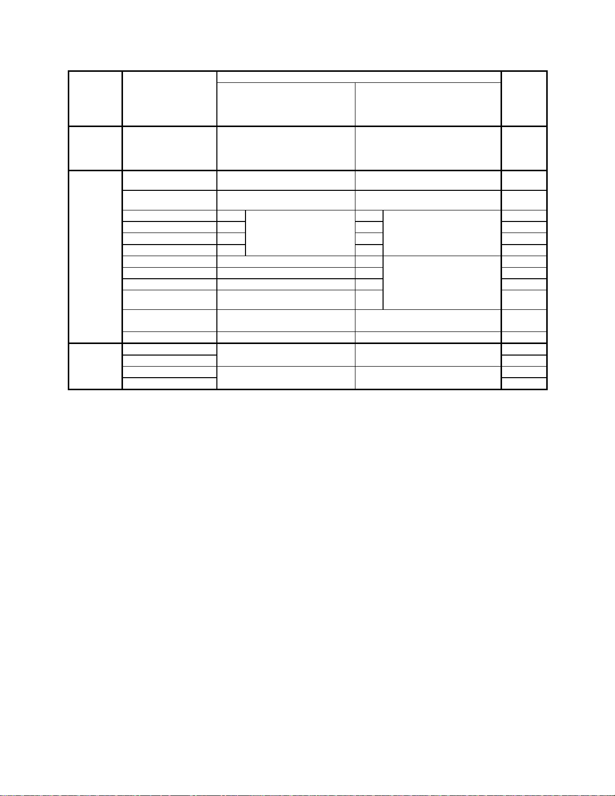
Table 1. Screw terminal definitions
Screw Screw terminal label Signal identity Directly
terminal
block
Relay
outputs
(J2 and J3)
Digital
signals (J5)
When the ERA-01 is connected to
DASCON-1 card
PB0, PB1, PB2,…PB7
- NO (normally open)
- C (common)
- NC (normally closed)
____
IRQ IN
___
CC
Relay contacts corresponding to
digital outputs PB0, PB1, PB2,…
and PB7 from the digital I/O “PB”
port
______________________
INTERRUPT INPUT
____________
CONV COMP
When the ERA-01 is connected to a
PIO-12/PIO-24 card or to a DAS1200/DAS-1600 card (at auxiliary
connector)
Relay contacts corresponding to
digital outputs PB0, PB1, PB2,… and
PB7 from the digital I/O “PB” port
INTERRUPT INPUT
________________________
INTERRUPT ENABLE
attached
pin on D
connector
(J1)
N/A*
1
2
PC0 PC0 Directly from lower bits PC0 Directly from lower bits 29
PC1 PC1 of the digital I/O “PC” PC1 of the digital I/O “PC” port. 28
PC2 PC2
port. (A 10 KΩ pull- up
PC2
(A 10 KΩ pull- up resistor
27
PC3 PC3 resistor is attached to each.) PC3 is attached to each.) 26
BSY BUSY PC4 Directly from upper bits 25
CH0 ADR CH ADDR 0 PC5 of the digital I/O “PC” port 24
CH1 ADR CH ADDR 1 PC6 (no pull-up resistors) 23
_________
LD ADR
__
R/H
_______________
LD CH ADDR
_______
RUN/HOLD
PC7
Digital signal common
22
21
GND Digital signal common Digital signal common 11
External AC 10 VAC from Keithley external 10 VAC from Keithley external N/A
power (J4) AC adapter, part number OPA-01 adapter, part number OPA-01 N/A
DC - Regulated 5 VDC from external Regulated 5 VDC from external 11
DC + supply supply N/A
*N/A = not applicable
Specifications
Relays
Number of relays: 8
Relay type: Form C (SPDT)
Contacts: Silver alloy
Contact rating: 3A at 125 Vrms or 28 VDC (resistive), Installation Category II
Contact life, mechanical: 10 million operations
Contact life, electrical: 100,000 operations at full load
Operate time: 20 ms max.
Release time: 10 ms max.
Other hardware
Breadboard area: 0.7 in x 1.2 in (1.78 cm x 3.05 cm) (8 x 13 solder pad matrix)
PC bus power available: +5V
Number of LEDs: (8 red, one per relay)
Environmental
Operating temperature range: 0 to 60 °C
Storage temperature range: -40 to +100
°
C
Humidity: 0 to 90% non-condensing
Power and Signal Requirements
+5V power: 760 mA typical, 800 mA max. (all relays energized)
Logic level to energize relay (make): "1" logic high
Switching load current for relay "off" (break): 0.018 mA
2
Page 3

Physical
Dimensions, with enclosure: 6.687 in L x 5.125 in W x 2.375 in H (17 cm L x 13.0 cm W x 6 cm H)
Dimensions, without enclosure: 6.187 in L x 4.687 in W x 1.3 in H (15.7 cm L x 11.9 cm W x 3.3 cm H)
Weight, with enclosure: 17 oz (0.482 kg)
Weight, without enclosure: 9 oz (0.285 kg)
Screw terminal wire spacing: 0.197 in (5 mm)
Screw terminal wire sizes: 12 - 22 AWG
Mounting holes (without enclosure): 0. 125 in (3.17 mm)
Safety precautions
The following safety precautions should be observed before using this product and any associated instrumentation. This product
may be used with hazardous voltages.
This product is intended for use by qualified personnel who recognize shock hazards and are familiar with the safety precautions
required to avoid possible injury. Read the operating information carefully before using the product.
General safety definitions
The types of product users are:
Responsible body is the individual or group responsible for the use and maintenance of equipment, and for ensuring that
operators are adequately trained.
Operators use the product for its intended function. They must be trained in electrical safety procedures and proper use of the
instrument. They must be protected from electric shock and contact with hazardous live circuits.
Maintenance personnel perform routine procedures on the product to keep it operating, for example, setting the line voltage or
replacing consumable materials. Maintenance procedures are described in the manual. The procedures explicitly state if the
operator may perform them. Otherwise, they should be performed only by service personnel.
Service personnel are trained to work on live circuits, and perform safe installations and repairs of products. Only properly
trained service personnel may perform installation and service procedures.
If a grounding screw
The
symbol on an instrument indicates that the user should refer to the operating instructions located in the manual.
The WARNING heading in a manual explains dangers that might result in personal injury or death. Always read the associated
information very carefully before performing the indicated procedure.
The CAUTION heading in a manual explains hazards that could damage the instrument. Such damage may invalidate the
warranty.
Installation safety
As described in the International Electrotechnical Commission (IEC) Standard IEC 664, the signal terminals are Installation
Category I and must not be connected to mains, except as noted in the specifications.
When connecting to sources, install protective devices to limit current and voltage to the card.
Operators and maintainers of this product must be protected from electric shock at all times. The responsible body must ensure
that users are prevented access and/or insulated from every connection point. In some cases, connections must be exposed to
potential human contact. Product users in these circumstances must be trained to protect themselves from the risk of electric
shock. If the circuit is capable of operating at or above 1000 volts, no conductive part of the circuit may be exposed.
is present, connect it to safety earth ground using the wire recommended in the user documentation.
3
Page 4

Operation safety
Exercise extreme caution when a shock hazard is present. Lethal voltage may be present on cable connector jacks or test fixtures.
The American National Standards Institute (ANSI) states that a shock hazard exists when voltage levels greater than 30V RMS,
42.4V peak, or 60VDC are present. A good safety practice is to expect that hazardous voltage is present in any unknown
circuit before measuring.
For maximum safety, do not touch the product, test cables, or any other instruments while power is applied to the circuit under
test. ALWAYS remove power from the entire test system and discharge any capacitors before: connecting or disconnecting
cables or jumpers, installing or removing switching cards, or making internal changes, such as installing or removing jumpers.
Do not touch any object that could provide a current path to the common side of the circuit under test or power line (earth)
ground. Always make measurements with dry hands while standing on a dry, insulated surface capable of withstanding the
voltage being measured.
Do not exceed the maximum signal levels of the instruments and accessories, as defined in the specifications and operating
information, and as shown on the instrument or test fixture panels, or switching card.
If you are using a test fixture, keep the lid closed while power is applied to the device under test. Safe operation requires the use
of a lid interlock.
Instrumentation and accessories shall not be connected to humans.
Maintenance and service for safety
Inspect the connecting cables, test leads, and jumpers for possible wear, cracks, or breaks before each use.
Before performing any maintenance, disconnect all power sources and test cables.
Cleaning
Keep the connections free of contaminants (such as dirt, oil, etc.) in order to maintain maximum insulation resistance. If the
connections become contaminated, clean them thoroughly with methanol and allow them to dry completely before use.
To clean the exterior of the plastic box, use a damp cloth or mild, water based cleaner. Clean the exterior of the box only, never
the circuit board. Do not apply cleaner directly to the box or allow liquids to enter or spill on the box.
Installation
Connecting the ERA-01 to the data acquisition card
You may use an optional C1800 cable to connect the ERA-01 to a data acquisition board. See Figure 2.
DASCON-1, PIO-12/24,
or
DAS-1600/1200 (connected at
auxiliary connector)
C1800 cable
ERA-01
Optional
OPA-01
power adapter
Figure 2. System configuration example
Connecting I/O signals to the screw terminals
The screw terminals and signals are identified in Figure 1 and Table 1. Logic levels and relay voltage and current limits are listed
in the specifications. Refer to this information when making connections.
WARNING
Ensure that no high voltages are accidentally connected to the wrong ERA-01 screw terminals. Some of
the ERA-01 screw terminals are directly connected to conductors in the digital I/O interface cable (i.e.
the C1800 or equivalent cable). The maximum voltage allowed for a C1800 cable is 30V RMS, 42.4V
peak, or 60VDC. Misconnected high voltages will not only damage the I/O board, and possibly the
computer, but also can cause cable insulation failure and shock hazard.
Always install the cover on the plastic box when high voltages are connected to the relay terminals.
4
Page 5

Power supply connections
The ERA-01 can be powered by the computer power bus or an external DC or AC power source. The information below will
help you choose and use the best option for your situation.
Using the computer power bus
Each relay on the board consumes about 0.095 A when energized. If all relays are active, the board draws about 0.76 A from the
computer +5 V power bus. The digital I/O board installed in the computer draws as much as 0.40 A. Therefore, the combined
ERA-01 and I/O board can draw as much as 1.16 A from the +5 V power bus. If you know that this additional current will not
overload the computer power bus, and you wish to operate the ERA-01 on internal computer power, then leave the internalexternal power selector switch, S1, in the INT PWR position (toward the D connector).
Using an external power source
However, if the +5 V power bus is already connected to several accessory boards, adding the ERA-01 may cause an overload. If
so, then power the ERA-01 externally. To use external power, first move the internal-external power selector switch, S1, to the
EXT PWR position (toward the heat sink). Then connect ONE of the following power sources:
• Option 1: Connect a regulated +5 VDC power source to the +DC and -DC screw terminals, which are located on the
external power terminal block (next to the heat sink).
CAUTION
Before turning on the DC power supply, ensure that the DC power supply is connected with correct
polarity. Incorrect polarity may cause circuit damage.
• Option 2: Connect a plug-in 10
the external power terminal block (next to the heat sink). The ERA-01 includes a +5 V voltage regulation circuit that
activates when external AC power is supplied.
VAC adapter (Keithley part number OPA-01) to the two AC terminals, which are located on
5
 Loading...