

Page 1

xx
Environment Signals
ZZZ
Plug-in Application
Printable Help Document
*P077140100*
077-1401-00
Page 2

Page 3

Environment Signals
Plug-in Application
ZZZ
Printable Help Document
w.tek.com
ww
077-1401-00
Page 4

Copyright © Tektronix. All rights reserved. Licensed software products are owned by Tektronix or its
subsidiaries or suppliers, and are protected by national copyright laws and international treaty provisions.
Tektronix products are covered by U.S. and foreign patents, issued and pending. Information in this
publication supersedes that in all previously published material. Specifications and price change privileges
reserved.
TEKTRONIX and TEK are registered trademarks of Tektronix, Inc.
®
SourceXpress
is a registered trademark of Tektronix, Inc.
Microsoft, Windows, Windows XP Professional, and Windows 7 are registered trademarks of Microsoft
Corporation.
Supports the Environment Signals Plug-in Version 3.0.x and above.
Help part number: 076–0415–00
PDF of Help system part number: 077–1401–00
Contacting Tektronix
nix, Inc.
Tekt ro
14150 SW Karl Braun Drive
P. O . B o x 500
Beaverton, OR 97077
USA
roduct information, sales, service, and technical support:
For p
In North America, call 1-800-833-9200.
Worldwide, visit www.tek.com to find contacts in your a rea.
Page 5

Table of Contents
Introduction
Welcome............................................................................................................. 1
Key features ......................................................................................................... 2
Documentation......................................... ................................ ............................. 3
Support information....... .................................. ................................ ....................... 3
Orientation
Elements of the display ............................................................................................ 5
Plug-in selection ....................................... .................................. ........................... 5
Signal Format selection............. ................................ ................................ ............... 6
Environment Scenarios ................................... .................................. ....................... 6
Compile button..................... ................................ ................................ ................. 6
Reset Plug-in button......... ................................ ................................ ...................... 11
Help button ............... ................................ ................................ .......................... 11
Emitter graphical displays ........................................................................................ 11
Table of Contents
Environment scenarios
Working with scenarios ................................. ................................ .......................... 15
Creating scenarios
Scenario definition area . . . . . . . . . . . . . . . . . . . . . . . . . . . . . . . . . . . . . . . . . . . . . . . . . . . . . . . . . . . . . . . . . . . . . . . . . . . . . . . . . . . . . . 15
Common scenario parameters ............................................................................... 16
Defining scenario durations........................ .................................. ........................ 16
Emitter basic parameters . . . . . . . . . . . . . . . . . . . . . . . . . . . . . . . . . . . . . . . . . . . . . . . . . . . . . . . . . . . . . . . . . . . . . . . . . . . . . . . . . . . . . 17
Scenario list
Scenarios list menu ............................... ................................ ............................ 19
Emitter menu
Emitter menu operations .. . .................................................................................. 20
Emitter advanced settings
Advanced emitter settings .............. .................................. ................................ ........ 23
Pulse emitter
Pulse emitter parameters . . . . . . . . . . . . . . . . . . . . . . . . . . . . . .................................... .. .. . . . . . . . . . . . . . . . . 23
Bluetooth emitter
Bluetooth emitter parameters .. .. .. .. .. .. .. .. .. .. . . . . . . . . . . . . . . . . . . . . . . . . . . . . . . . . . . . . . . . . . . . . . . . . . . . . . . . . . . . . 23
CDMA emitter
CDMA emitter parameters......................... ................................ .......................... 23
W-CDMA emitter
W-CDMA emitter parameters . . . . . . . . . . . . . . . . . . . . . . . . . . . . . . . . . . . . . .......................................... 24
Environment Printable Help Document i
Page 6

Table of Contents
Digital Modulation emitter
Digital Modulation emitter parameters . .................................................. .. .. . . . . . . . . . . . . . . 24
Setup
Hopping
Power Ramp
Analog Modulation emitter
Analog Modulation emitter parameters . . . . . . . . . . . . . . . . . . . . . . . . . . . . . . . . . . . . . . . . . . .......................... 30
DVB-T emitter
DVB-T emitter parameters . . . . . . . . . . . . . . . . . . . . . . . . . . . . . . . . . . . . . . . . . . . . . . . . . . . . . . . . . . . . .. .. .. .. .. .. .......... 31
GSM emitter
GSM emitter parameters . . . . . . . . . . . . . . . . . . . ............................ .. . . . . . . . . . . . . . . . . . . . . . . . . . . . . . . . . . . . . 31
LTE (Long Term Evolution) emitter
LTE emitter parameters . . . . . . . . . . . . . . . . . . . . . . . . . . . . . . . . . . . . . . ................................................ 32
Noise emitter
Noise emitter parameters. .. .. . . . . . . . . . . . . . . . . . . . . . . . . . . . . . . . . . . . . . . . . . . . . . . . . . . . . . . . . . . . . .................... 33
OFDM emitter
OFDM emitter parameters ........................... .. .. . . . . . . . . . . . . . . . . . . . . . . . . . . . . . . . . . . . . . . . . . . . . ........ 33
Frame Settings tab
Preamble tab
Header tab
Payload tab
Symbol tab
Hopping tab
P25 emitter
Setup tab ........ ................................ .................................. ........................ 24
PRBS Editor.............................................................................................. 26
Hopping tab............................................................................................... 27
Power Ramp tab.................................... .................................. .................... 29
Frame Settings tab . ................................ .................................. .................... 33
Preamble tab.............................................................................................. 34
Header tab ................................................................................................ 35
Payload tab ............................................................................................... 35
Symbol tab................................................................................................ 36
Subcarriers for symbols
Subcarriers for symbols ............................................................................ 38
Defining the Pattern................................................................................. 39
PRBS Editor ......... ................................ ................................ ................ 40
Modulation types available ........................................................................ 40
Defining subcarrier positions .. . . . . . . . . . . . . . . . . . . . . . . . . . . . . . . . . . . . . . . . . . . . . ........................ 41
Amplitude Phase Profile
Amplitude Phase Profile............................ .................................. .............. 41
Hopping tab............................................................................................... 42
ii Environment Printable Help Document
Page 7

Table of Contents
P25 emitter parameters . . . . . . . . . . . . . . . . . . . . . . . . . . . . . . . . . . . . . . . . . . . . . . . . . . . . . . . . . . . . . . . . . ...................... 43
Radar emitter
Radar emitter
Pulse Envelope
Pulse Envelope tab....................................................................................... 43
Modulation
Modulation tab ........................................................................................... 45
PRBS Edito
Staggered PRI
Staggered PRI tab........................................................................................ 55
Offsets
Offsets tab .................... ................................ ................................ ............ 59
Hoppin
Hopping tab............................................................................................... 60
Antenna
Antenna tab ................... .................................. ................................ .......... 63
Tones emitter
Tones emitter parameters . . . . . . . . . . . . . . . . . . . . . . . . . . .......................................................... 66
Defined emitter
User
User Defined emitter parameters .......... .. .. .. . . . . . . . . . . . . . . . . . . . . . . . . . . . . . . . . . . . . . . . . . . . . . . . . . . . . . . . . . . . . 66
WiFi emitter
WiFi emitter parameters ............. .. .. . . . . . . . . . . . . . . . . . . . . . . . . . . . . . . . . . . . . . . . . . . . . . . . . . . . . . . . . . . . . ........ 67
WiMAX emitter
WiMAX emitter parameters . .. . . . . . . . . . . . . . . . . . . . . . . . . . . . . . . . . . . . . . . . . . . . . ................................ .. 68
parameters .......... ................................ .................................. ........ 43
Modulation settings ............................... .. . . . . . . . . . . . . . . . . . . . . . . . . . . . . . . . . . . . . . . . . . . . . . . . . 46
r
PRBS Editor ......... ................................ ................................ ................ 55
g
Licensing
Licensing ..... ................................ ................................ .................................. .... 69
Index
Environment Printable Help Document iii
Page 8

Table of Contents
iv Environment Printable Help Document
Page 9

Introduction Welcom e
Welcome
The Environment signal plug-in is a waveform creation application that allows you to emulate realistic
signal interference.
The standards that are supported in the Environment plug-in include:
• Bluetooth • DVB-T • P25
•CDMA •GSM
•W-CDMA
xxx
•LTE •WiMAX
Along with the various signal standards, it also a llows seamless integration of signals created using other
waveform plug-in capabilities such as:
1
• Radar
•OFDM
1
• Analog modulation
• Digital modulation
xxx
1
Requires additional licensing.
1
1
• Pulses
•Noise
• Tones
• User created waveforms
The Environment signal plug-in is designed to integrate and operate seamlessly as an enhancement to
the following products:
•WiFi
SourceXpress waveform creation software version 5.3 and above
AWG70000 series arbitrary waveform generators s oftware version 5.3 and above
AWG5200 series arbitrary w aveform generators software version 6.0 and above
Once installed, the plug-in becomes available as another waveform plug-in application in SourceXpress.
illustrations in this document show the Environment signals plug-in viewed from the SourceXpress
The
application. The plug-in interface is identical whether used from SourceXpress or installed on a generator.
Environment Printable Help Document 1
Page 10

Introduction Key features
Key features
The Environment signal plug-in allows you to build scenarios of v arying types of signal interference.
Some of the key features include:
Build a variety of scenarios
Ability to build up to 50 scenarios
A large variety of emitters available
ty to add up to 100 emitters to a scenario
Abili
Compile both scenario waveforms and sequences
Control durations of each emitter
Set emitter power, start time, center frequency/baseband offset
Import user created interference signals
Create RF/IF or IQ signal formats
2 Environment Printable Help Document
Page 11

Introduction Documentation
Documentation
In addition to this application Help system, the following documentation is available for the software.
All documentation is available on the Tektronix Web site (www.tek.com/manual/downloads
To read about Use these documents
Environment plug-in operation and user interface
help
Environment plug-in programmer commands
SourceXpress operation and user interface help Access the SourceXpress application help from the Help menu for
SourceXpress programmer commands Access the SourceXpress programmer manual for the syntax of remote
Connected instrument operation and user
interface help (such as an AWG70002A or
AWG5204)
Access the plug-in application help from the plug-in Help menu for
information on all controls and elements on screen.
The Environment plug-in help systemisalsoavailableinPDFformat
located in the program’s installation folder and also available on the
Tektronix web site.
Access the plug-in programmer manual for the syntax of remote commands
specific to the plug-in.
This is available on the Tektronix web site.
information on all controls and elements on screen.
The SourceXpress help system is also available in PDF format, available
on the Tektronix web site.
commands.
This document is available in PDF format located in the program’s
installation folder and also available on the Tektronix web site.
For operation and interface help of a connected instrument, refer to the
instrument’s documentation.
This is available with the instrument or on the Tektronix web site.
).
Connected instrument programmer commands
(such as an AWG70002A or AWG5204)
xxx
Support information
Tektronix offers the following services in support of their products:
Technical Support. For application-related questions about a Tektronix product, contact us by
telephone or email.
Service Support. For service-related questions about a Tektronix product, contact us by telephone or
email.
Tektronix also offers e xtended warranty and calibration programs as options on many products. Contact
your local Tektronix distributor or sales office.
For programming information of a connected instrument, refer to the
instrument’s documentation. This is available with the instrument or on
the Tektronix web site.
Environment Printable Help Document 3
Page 12

Introduction Support information
4 Environment Printable Help Document
Page 13

Orientation Elements of the display
Elements of the display
The main areas of the application window are shown in the following figure.
Plug-in selection
Use the Plug-in pull-down menu to select the Environment plug-in application. The plug-in pull-down
menu varies depending on the installed applications.
NOTE. The Environment plug-in requires a license to create waveforms.
Refer to Licensing
(see page 69).
Environment Printable Help Document 5
Page 14

Orientation Signal Format selection
Signal Format selection
The Environment plug-in supports generation of two signal formats (RF/IF and IQ). This allows you to
create baseband waveforms (complex signals with I and Q waveforms) and RF/IF waveforms (real signal
waveforms).
Baseband signals (IQ format): When the IQ signal format is selected, a baseband complex signal is
generated f
assigned to a single channel which will be upconverted to the user defined center frequency. Refer
to the compile settings
RF signals (RF/IF format): When the RF signal format is selected, one waveform file is generated for
each scenario if the setting is to create a single waveform in the compile settings.
or each scenario. If the instrument contains an IQ modulator, a complex signal can be
(see page 6).
Environment Scenarios
The Environment Scenarios area contains both the current list of scenarios and the emitter selections (for
the selected scenario). A graphical representation of each emitter is also provided. The emitters can be
shows in relation to emitter durations or a spectral graph of each emitter.
Refer to:
Environment Scenarios list and menu
Emitter menu operations (see page 20)
Compile button
Use the Compile button to compile all Environment Scenarios and place the scenari
Waveforms list of the host application. Sequences (if enabled) are placed in the Sequence list.
Use the Compile settings button to edit the compilation settings.
(see page 19)
o waveforms into the
6 Environment Printable Help Document
Page 15

Orientation Compile button
NOTE. When c
ompiling, all scenarios in the Environment Scenarios list are compiled.
Compile settings
Environment Printable Help Document 7
Page 16

Orientation Compile button
Item Description
Channel Assignment The channel assignment area changes based on several factors:
selection (RF/IF verses IQ).
RF channel ass
I and Q channel
assignmen
IQ channel assignment
ignment
t
Signal Format
Generator capabilities (IQ modulator to create IQ waveforms).
Choose the channel to associate with the compiled RF waveform. The selected channel is
also used to defi ne the amplitude ranges.
Choose the channels to associate with the compiled I and Q waveforms. The selected
channel i
See the information about the “Use Internal IQ Modulator” selection.
salsousedtodefine the amplitude ranges.
If the generator has IQ modulator capabilities (digital up converter), you are able to assign
the complex IQ waveform to a channel.
Choose
also used to defi ne the amplitude ranges.
See the information about the “Use Internal IQ Modulator” selection.
Correction Files Check the box to apply a correction file directly to the scenario when compiling.
Use th
Onceavalidfile path is entered, the Correction Settings icon
display the Frequency Response screen.
For R
For IQ signal formats, you can choose either a single IQ correction file or correction files
for I and Q.
the channel to associate with the compiled IQ waveform. The selected channel is
e browse folder icon
F signal formats, you apply a single correction file to the scenario.
to navigate to a saved correction file.
is enabled. Select to
8 Environment Printable Help Document
Page 17

Orientation Compile button
Item Description
Create each Environment
Scenario as se
quence
If checked, each scenario will be compiled as a sequence.
If unchecked,
each scenario is created as one single waveform, which may take more
memory to compile, depending on the settings.
This check box is not shown if the instrument does not have the sequence option.
Adjust Frequency for
wrap-around
When a waveform is in continuous play mode, it repeats when the end is reached. It is
important to
take care of the phase continuity between the start and end of the waveform.
Discontinuity in the waveform produces frequency spurs.
The application might adjust the Sampling Rate, waveform length, and other waveform
to make the phase continuous at the end and beginning of the waveform.
a complex IQ waveform is created during compile.
Use Interna
l IQ Modulator
properties
If checked,
This check box is not shown if the instrument does not have an internal IQ modulator.
Overwrite existing
waveform(s)/sequence(s)
If checked, a scenario with the same name (in the scenario list) is o verwritten with no
warnings.
Compile only The compiled scenarios are simp ly entered into the Waveforms and Sequences lists.
Compile and assign to
channel
ter assign
Play af
ng Rate
Sampli
Auto calculate
The compiled scenarios are automatically assigned to the selected c hannel.
The scenarios are compiled and listed in the waveform and sequence lists depending on
e of the "Create each Environment Scenario as sequence" setting.
the stat
ked, the scenarios starts to play out immediately after compiling.
If chec
s the default method to set the sampling rate. The application creates a sampling
This i
rate based on the settings chosen.
l
Manua
Select to enter a specific sampling rate.
Compile Compiles the scenarios.
When compiling, all scenarios in the E nvironment Scenarios list are compiled.
xxx
Correction file frequency response
If applying an RF correction file, the Frequency Response screen shows plot information and provides
Advanced options to apply a Gaussian filter or remove Sin(x)/x distortions.
Environment Printable Help Document 9
Page 18

Orientation Compile button
If applying an I/Q correction file (to a pair of I and Q waveforms), the Frequency Response screen shows
plot information and provides Advanced options to apply a skew.
When applying an I/Q correction file you can choose either a single IQ correction file or correction files for
I and Q. The Frequency Response screen shows plot information and provides Advanced Options to apply
a Gaussian filter or remove Sin(x)/x distortions. When selecting I and Q correction files, separate files for I
and Q are shown in the Frequency Response window.
10 Environment Printable Help Document
Page 19

Orientation Reset Plug-in button
Reset Plug-in button
Returns all plug-in settings to their default values.
Help button
Click User Manual to display the plug-in Help file which provides information about the selected plug-in
application. Click About to display the selected plug-in’s version information.
Emitter graphical displays
The emitter definition area provides two types of graphical di
in the scenario when compiled.
Duration: provides a graphical representation of the emitte
Spectrum provides a plot of the emitters represented as amplitude verses frequency in relation to
each other.
splays of the emitters selected to be included
r’s durations in relation to each other.
Environment Printable Help Document 11
Page 20

Orientation Emitter graphical displays
Duration display
The duration displays a time-bar for each emitter’s duration. The emitter must be turned on.
As seen in the illustration here, there are three emitters. As shown, the duration display represents the
following aspects:
The Pulse is the anchor emitter.
Each emitter has a color assignment.
The Scenario Duration is set to Anchor. So the Pulse duration is the total scenario duration, at 280 μs.
The Radar emitter has a duration of 85 μs but has a Start Time (delay) of 10 μs from the anchor emitter.
The Tones emitter has a duration of 100.043 μs.
All durations are within (less than) the Anchor emitter.
Spectrum display
The spectrum displays a spectrum plot for each emitter. The emitter must be turned on.
As seen in the illustration here, there are three emitters. As shown, the spectrum display represents
the following aspects:
Each emitter has a color assignment.
The center frequency of each emitter.
The amplitude relationship between emitters.
12 Environment Printable Help Document
Page 21

Orientation Emitter graphical displays
Environment Printable Help Document 13
Page 22

Orientation Emitter graphical displays
14 Environment Printable Help Document
Page 23

Environment scenarios Working with scenarios
Working with scenarios
The Environment plug-in displays all existing scenarios. As you select scenarios, the emitters table display
the emitters for the selected scenario. You can only display the e mitters table for one scenario at a time.
NOTE. New sce
See the Scenarios list operations
narios are created with a single Pulse emitter with all default settings.
Scenario definition area
The Scenario definition area contains two areas to add and define emitter parameters:
Common scenario parameters (see page 16)
Basic emitter parameters (see page 17)
(see page 19) for details about managing the scenario list.
Environment Printable Help Document 15
Page 24

Environment scenarios Common scenario parameters
Once an emitter is added to the Scenario definition area, selecting the emitter displays its Advanced
settings in tabs at the bottom of the screen.
See the section Advanced emitter settings
Common scenario parameters
Each scenario has three basic parameters that are applicable to the selected scenario:
Magnitude (Peak): If the Signal Format is RF/IF, set the signal amplitude in units of dBm.
Amplitude: If the Signal Format is IQ, set the signal amplitude in units of peak-to-peak volts.
Scenario Duration: Choose to set the scenario’s duration to either match the Anchor emitter’s duration
or to set the duration manually. See Defining scenario durations
(see page 23) to configure emitters.
(see page 16) for more information.
Defining scenario durations
The total scenario duration is determined by the Scenario Duration setting.
Anchor sets the scenario duration to the duration of the emitter (plus start time) chosen to be the anchor.
Manual lets you enter a
Using the Anchor as duration
When the Scenario Duration is set to use the Anchor, the scenario duration equals the duration of the
emitter chosen to be the Anchor. If the emitter has a Start Time, this is added to the scenario duration.
scenario duration independent of the emitters.
16 Environment Printable Help Document
Page 25
Environment scenarios Emitter basic parameters
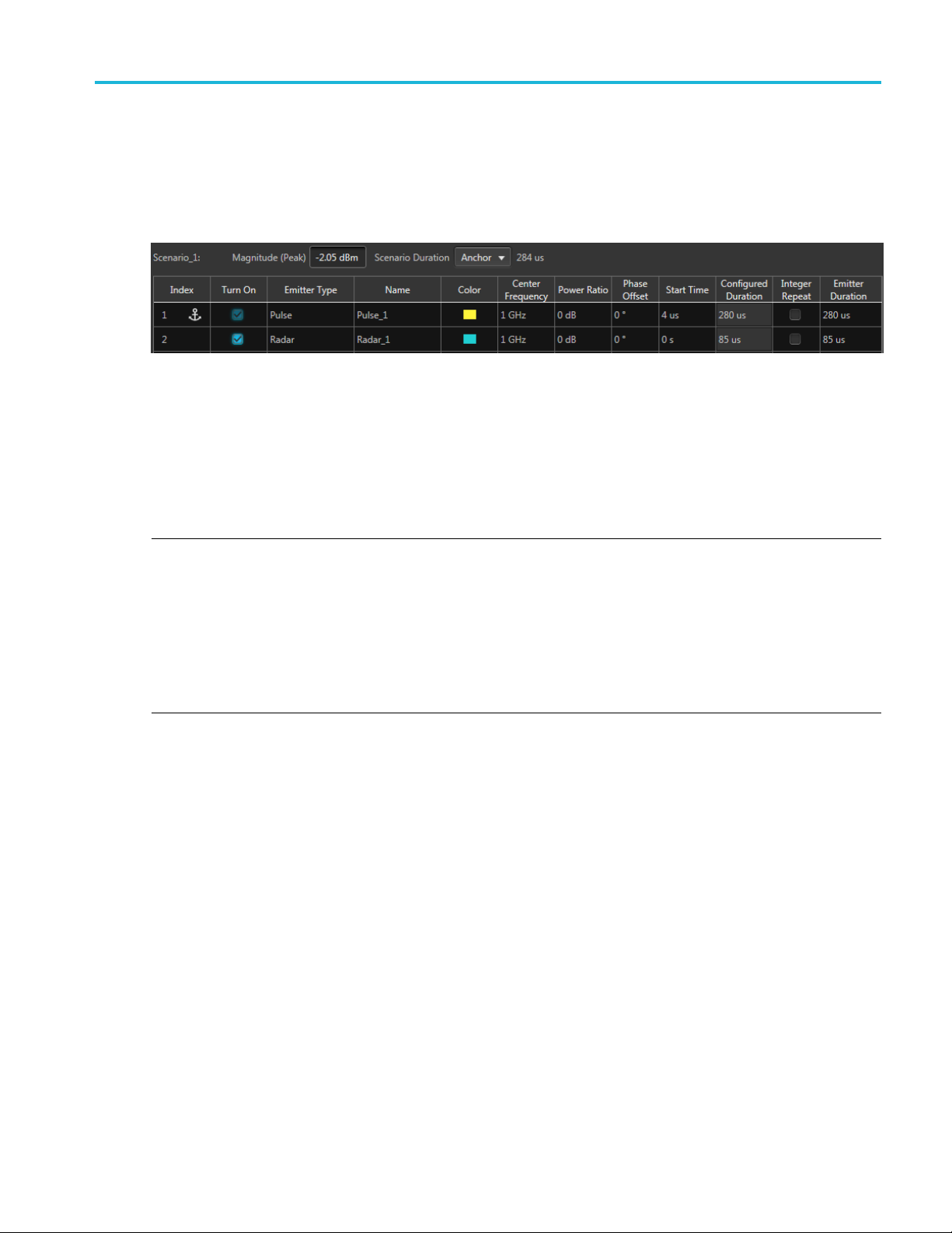
In the example below, the Scenario Duration is set to Anchor. The Anchor emitter is chosen to be the
Pulse emitter, which has an Emitter Duration of 280 μs. The Pulse emitter also has a Start Time of 4 μs.
So the total Sc
The Radar emitter duration is less than the Anchor emitter duration, which allows the Radar emitter signal
to complete i
Note that the emitters have both a Configured Duration and an Emitter Duration field.
enario Duration is set to 284 μs.
ts entire cycle.
The Config
The Configured Duration is not adjustable from the emitter table, only from the emitter’s advanced settings.
The Emit
emitter’s duration in this field.
NOTE. Changing the emitter duration to a value different than its configured duration will impact the
emitter signal.
Shortening the Emitter Duration will truncate the si gnal. Lengthening the Emitter Duration causes the
emitter signal to repeat (as many times necessary) to match the modified Emitter Duration time. But the
final repeated cycle of the signal might be truncated. If an emitter’s configured duration is such that there
is dead time when compared to the Anchor emitter’s duration, consider using the Integer Repeat function.
This
frame, without truncating the signal.
ured Duration is the duration of the emitter as configured in the emitter’s Advanced settings.
ter Duration field is initially set to match the Configured Duration, but you can adjust the
causes the emitter signal to repeat as many times as possible, within the Anchor duration time
Using Manual duration
Setting the Scenario Duration to Manual allows you to directly specify the scenario duration. No emitters
impact the duration.
Emitter basic parameters
Each emitter contained within a scenario has basic parameters that are displayed next to the selected
scenario. These settings are independent between the scenario emitters, although the chosen anchor may
impact other emitters, based on duration settings.
Environment Printable Help Document 17
Page 26

Environment scenarios Emitter basic parameters
NOTE. Detailed emitter settings are displayed at the bottom of the screen. Refer to the specific emitter in
the Advanced emitter settings
Item Description
Index
Turn On
Emitter Type Use the pull-down list to select an emitter.
Name
Color Select the color to use to represent the emitter in both the Duration and Spectrum
Center Frequency Available for RF/IF signal format.
(see page 23) section.
Lists the index number of the emitter. Up to 100 emitters can be defined per scenario.
This field a
waveform is limited by the anchor signal duration.
or manual). This will cause the emitter s ignal to be truncated to the length of the
scenario duration.
When selected, the emitter signal will be included when the scenario is compiled.
Use this field to rename the emitter. The emitter name is used in the Duration graph.
By default, the emitter name uses the Emitter Type name appended with a numerical
value.
graphs.
Adjust the center frequency for each emitter.
lso includes two possible icons: Anchor and warning icons.
indicates the emitter the anchor emitter. The overall duration of the compiled
indicates that the emitter’s duration is longer than the scenario duration (anchor
NOTE. ForUserDefined emitters (user supplied RF waveforms), the center
frequency and phase offset is obtained from the waveform file.
Baseband Offset Available for IQ signal format.
Adjust the Baseband Offset for each emitter.
Power Ratio
Phase Offset Enter a phase offset (of the emitter) with respect to other emitters within the scenario.
Enter a relative power level (of the emitter) with respect to other emitters within the
scenario.
NOTE. ForUserDefined emitters (user supplied RF waveforms), the center
frequency and phase offset is obtained from the waveform file.
Start Time Select a start time for the emitter to start in relation to the other emitters in the scenario,
effectively adding a delay to the emitter signal.
If the emitter is the anchor, the overall scenario duration is increased by the additional
start time.
Configured Duration Displays the current configured duration for the emitter. This is not adjustable from the
emitter table. The duration is defined in the advanced emitter setup tabs.
18 Environment Printable Help Document
Page 27

Environment scenarios Scenarios list menu
Item Description
Integer Repeat
Emitter Durat
xxx
ion
Selecting Integer Repeat causes the emitter signal to repeat (as many times as
possible) com
defined by the Scenario Duration.
Defines the signal duration for the specific emitter in the final compiled scenario.
If the value is less than the configured duration, the signal will be incomplete.
If the v alue i
the emitter duration is reached. This can lead to incomplete cycles and truncated
signals. Use the Integer Repeat function for the emitter to avoid incomplete and
truncated s
plete full cycles of the emitter’s Configured Duration within the time
s more than the configured duration, the configured duration repeats until
ignals.
Scenarios list menu
Initially, the Environment plug-in contains one default Scenario with a single Pulse emitter. Right-clicking
in the Envi
cancontainupto50scenarios.
ronment Scenario list opens a menu that allows you to manage the scenario list. The list
The Environment Scenario menu contains the following options:
Item Description
Add Scenario Creates an new Scenario containing one Pulse emitter. The Scenario is placed at the bottom
of the Environment Scenarios list. All parameters of the new Scenario are set to their default
values.
Open Scenario(s) Allows you to select and open an existing setup file containing scenarios. The scenarios are
added to the Environment Scenarios list.
If the setup file contains multiple scenarios, you are presented with an Available Environment
Scenarios screen to select which scenarios to import.
If a scenario name already exists, you’ll be presented with a screen to decide how to handle the
scenario.
Waveforms and Sequences, that may have been saved with the setup file, are not imported. If
you want the saved waveforms and sequences, use the File menu of the host application.
Environment Printable Help Document 19
Page 28
Environment scenarios Emitter menu operations
Item Description
Combine Scenarios
Allows you to create a new scenario that includes all emitters contained in the scenarios
selected to combine.
The order in wh
the new combined scenario.
The anchor emitter for the new combined scenario is the anchor emitter from the scenario
selected firs
ich you select the scenarios to combine dictate the order of the emitters in
t.
NOTE. The order in which the emitters are displayed has no impact on the compiled scenario.
Make a Copy Creates a duplicate copy of the selected scenario.
Rename Allows you t
Remove
xxx
Deletes the
This menu item is not selectable if there is only one scenario in the list. At least one scenario
must always exist.
o rename the selected scenario.
selected Scenario.
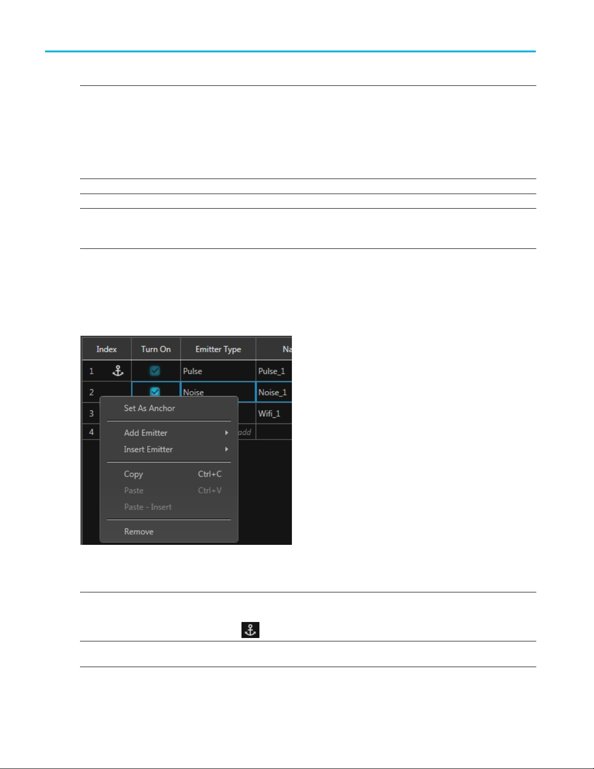
Emitter menu operations
With any emitter selected, a right-mouse click in the table displays a menu of operations.
Item Description
Set As Anchor Chooses which emitter to use as the anchor.
The overall duration of the final waveform is limited by the anchor signal duration.
Add Emitter
The anchor icon
Select to add a new emitter type to the selected scenario. Use the drop-down list to select the
emitter type to add. The new emitter is appended to the end of the existing emitters.
is placed in the index column of the anchor emitter.
20 Environment Printable Help Document
Page 29

Environment scenarios Emitter menu operations
Item Description
Insert Emitter
Copy Copies the sel
Paste
Select to insert a new emitter type into the selected scenario. Use the drop-down list to select
the emitter ty
pe to add. The new emitter is inserted above the currently selected emitter.
ected emitter definition (or definitions) in preparation to paste into a scenario.
Pastes the co
pied emitter definition(s) over the selected emitter definition(s).
NOTE. The anchor emitter can not be pasted over.
Emitter definitions can be copied and pasted between scenarios.
Paste-Insert
Pastes the
copied emitter definition(s) into the scenario above the selected emitter definition.
Remove D eletes the selected emitters.
You can als
o press Delete on the keyboard.
There are several ways to select multiple emitters:
Left-mouse click on an emitter, continue to hold the left-mouse button and slide the selection
either up
or down to highlight the emitters.
Select an emitter, then hold the Shift key to select continuous emitters.
Hold the Ctrl key and select emitters.
NOTE. Th
xxx
e anchor emitter can not be removed.
Environment Printable Help Document 21
Page 30

Environment scenarios Emitter menu operations
22 Environment Printable Help Document
Page 31

Emitter advanced settings Advanced emitter settings
Advanced emitter settings
This section contains the information for about advanced parameters available for each emitter. The
advanced parameters appear as tabbed sections at the bottom of the screen.
The links below provide quick a ccess to each emitter ’s advanced settings.
Pulse emitter parameters (see page 23) Noise emitter parameters (see page 33)
Bluetooth emitter parameters (see page 23) OFDM emitter parameters (see page 33)
CDMA emitter parameters (see page 23) P25 emitter parameters (see page 43)
W-CDMA emitter parameters (see page 24) Radar emitter parameters (see page 43)
Digital Modulation emitter parameters (see page 24) Tones emitter parameters (see page 66)
Analog Modulation emitter parameters1 (see page 30) User Defined emitter parameters (see page 66)
DVBT emitter parameters (see page 31) WiFi emitter parameters (see page 67)
GSM emitter parameters (see page 31) WiMAX emitter parameters (see page 68)
LTE emitter parameters (see page 32)
xxx
Pulse emitter parameters
Item Description
Pulse Width Enter the pulse width.
PRI
Repeat Count Select the number of times to repeat the pulse emitter signal. The emitter duration
xxx
The Pulse Repetition Interval (PRI) value sets the configured emitter duration and is
displayed as seconds. The PRI value can be affected by the Pulse Width setting.
(PRI) increases to match the repeat count.
Bluetooth emitter parameters
Item Description
Standard Choose the Bluetooth standard to create.
LE 1M, LE 2M, LE Coded, BR, EDR
Modulation
DataRate Fixedto1Mbps.
xxx
FixedtoGFSK.
CDMA emitter parameters
Item Description
Link
Number of channels Set the number of traffic channels to 9, 12, or 15.
Set the CDMA channel type to Forward or Reverse.
Environment Printable Help Document 23
Page 32

Emitter advanced settings W-CDMA emitter parameters
Item Description
Radio configuration Set the radio configuration to RC1, RC2, RC3, RC4, or RC5.
Data rate
xxx
The available data rates is dependent on the Radio configuration setting.
RC1: 1200 bps,
RC2: 1800 bps, 3600 bps, 7200 bps, 14400 bps.
RC3: 1500 bps, 2700 bps, 4800 bps, 9600 bps.
RC4: 1500 bps
RC5: 1800 bps, 3600 bps, 7200 bps, 14400 bps.
2400 bps, 4800 bps, 9600 bps.
, 2700 bps, 4800 bps, 9600 bps.
W-CDMA emitter parameters
Item Description
Link
Down link mode
With CPICH channel Select this to include a CPICH channel.
Number of Channels Set the number of channels.
Number of HS-PDSCH channels Set the number of channels to 4 or 8.
Number of DPCH channels Select the number of channels, 1–6. This option is available when you select Down in
Data rate When the Link type is Up, the data rates can be set to 15 kbps 30 kbps, 60 kbps, 120
xxx
SetthelinktypetoDownorUp.
Set the mode to DPCH or TestMode 1–6.
This option is available when the Link type is set to Down.
This option is available when you select Down in the Link list a nd TestMode4 in the
Down Link Mode list.
When the Link is set to Up, the number of channels is from 1 to 6.
When the Link type is set to Down, the number of channels varies based on the
Down Link mode.
This option is available when you select Down in the Link list a nd TestMode6 in the
Down Link Mode list.
the Link list and DPCH in the Down Link Mode list, or when you select Up in the Link list.
kbps, 240 kbps, 480 kbps, or 960 kbps.
When the Link type is Down, the data rate is fixedat15kbps.
Digital Modulation emitter parameters
Setup tab
Item Description
Digital Modulation setup parameters
Data
Pattern
All Zero
All One Sends a sequence of binary 1 symbols.
24 Environment Printable Help Document
Select the data source:
Sends a sequence of binary 0 symbols.
Page 33
Emitter advanced settings Setup tab
Data
PRBS Select the PRBS type from the following: 7, 9, 15, 16, 20, 21, 23, 29, 31, and User Defined.
To edit the bit
display the PRBS Editor
Pattern
File
Coding Depending on how the receiver is set to receive the information bits, coding can be applied on
Digital Mod
Modulation
nDPSK
APSK (16, 32,
64)
ulation
Phase
Rotation
n
Advanced
Parameters
Enter a pattern of 0s and 1s up to a maximum of 256 digits in the text field that appears.
Select the base data file to be used by entering the path or browsing to the file. The supported
formats are .txt.
the bit str
Specify the coding type: None, Gray, Differential.
Select a mo
parameters that are displayed upon selection. Below are descriptions of the various additional
parameters.
Available when modulation is set to n DPSK.
Set the ph
Set the n value of n-DPSK modulation. n must be a power of 2.
Available when modulation is set to one of the APSK types.
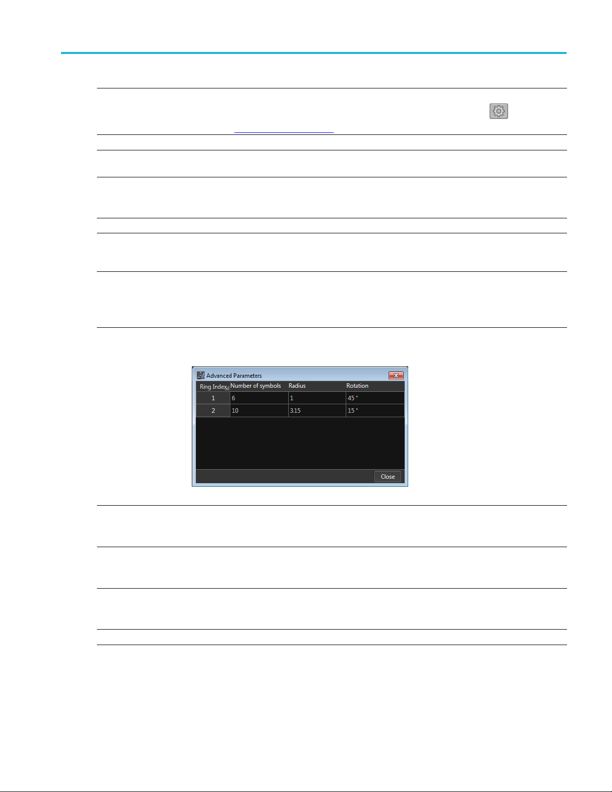
The Adv
symbol arrangement.
sequence, select User Defined. This displays the PRBS Editor icon
(see page 26) dialog screen.
eam.
dulation type from the pull-down list. Some modulation types have additional
ase in degrees for the Differential PSK Modulation.
anced Parameters displays how the symbols are arranged. Use the fields to define the
. Select to
The number of symbols must equal the APSK type selected.
FSK
FSK Peak
Deviation
CPM
Index
ASK
ASK Mod
Index
Symbol Rate Enter the symbol rate for modulation.
Available when modulation is set to one of the FSK types.
Enter the FSK peak deviation value in Hz.
Continuous Phase Modulation uses a multi-h phase c oded scheme, where h is the modulation
index.
Choose one of the predefined modulation index pairs.
Available when modulation is set to ASK.
Enter the ASK modulation index from 0 to 200%.
Environment Printable Help Document 25
Page 34
Emitter advanced settings PRBS Editor
Filter
Filter
Window
Convolution Length
xxx
The filter selection is dependent on the M odulation selection.
Select the filt
Gaussian, Triangular, Edge, Half-Sine, and User Defined.
User Defined
Selecting Us
use the folder icon to browse to a filter file).
A filter file allows users to provide the filter coefficients. The file should have header information
containing S
For example:
SamplesPerSymbol = 50
Select the window type from the following: None, Triangular, Hamming, Hanning, Blackman,
Kaiser, Blackman Harris, Exact Blackman, Flat Top, Tapered Cosine, and Chebyshev Ripple.
Enter the convolution length.
Convolution Length defines the number of adjacent symbols to consider while filtering the symbol.
This in
er from the following options: Rectangular, Raised Cosine, Root Raised Cosine,
er Defined provides a filename dialog box to enter a path to a user defined filter file (or
amples to be considered per symbol followed by filter coefficients.
-0.000007
-0.000014
-0.000021
-0.000028
-0.000034
-0.000041
-0.00004
....
turn defines the number of filter taps.
8
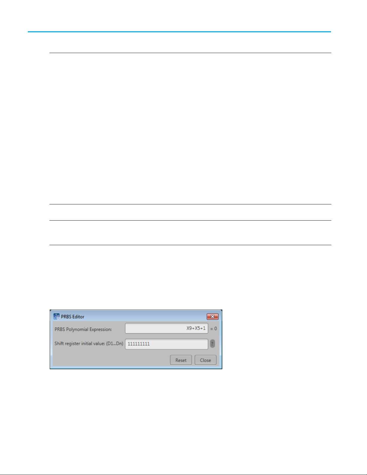
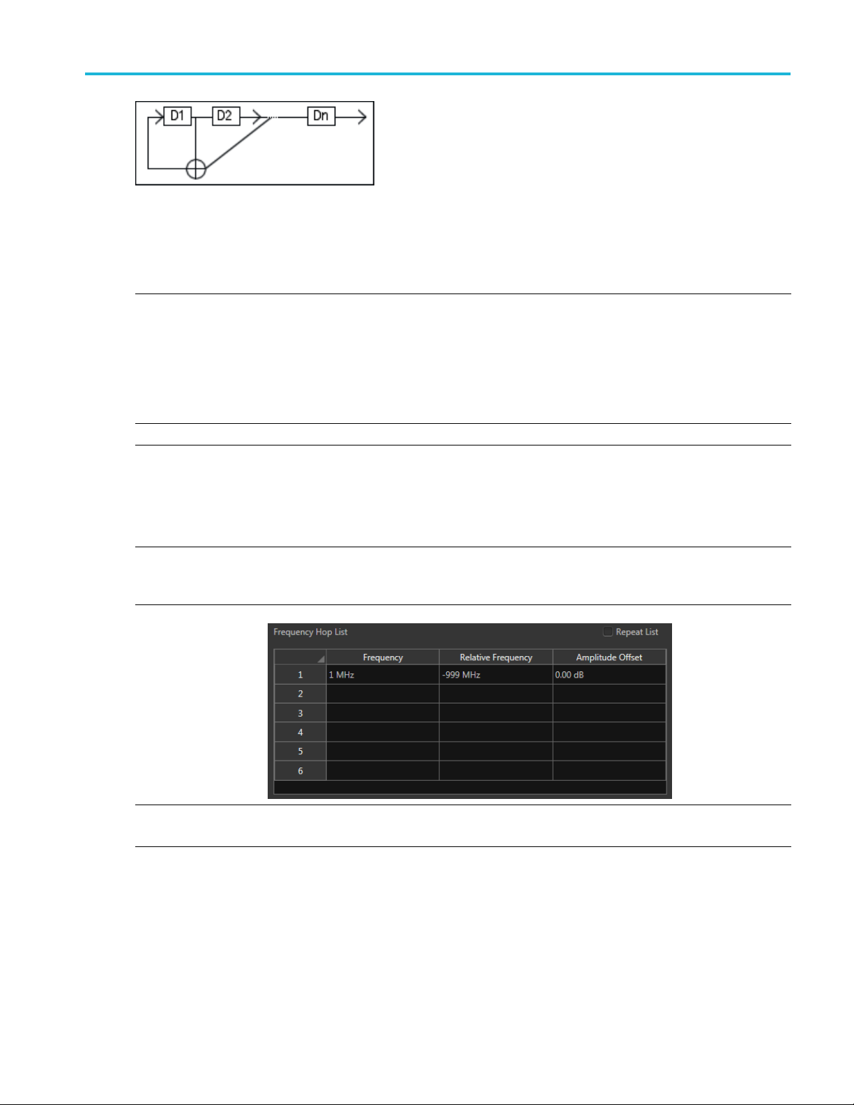
PRBS Editor
This dialog box is displayed when clicking PRBS Editor icon when PRBS is set to User Defined for
the Data and Pilot pattern type. (Symbols tab).
PRBS sequences are generated by a feedback shift register. The number (#) following PRBS indicates the
length of the generating shift register. For instance, a shift register with 16 memory cells is required to
generate a PRBS 16 sequence. The pseudo-random sequence of a PRBS generator is determined by the
number of registers and the feedback.
26 Environment Printable Help Document
Page 35
Emitter advanced settings Hopping tab
Hopping tab
Item Description
Hopping Pat
Custom Hop
Hop Time
Symbols P er Hop Symbols per Hop determines how many Sy mbols occur between each Hop. The value applies to
tern
ping Pattern
Three hoppi
Custom: Hops are based on the Frequency Hop List.
Pseudo Random List: Hops are chosen randomly (based on PRBS selection) from the Frequency
Hop List.
Pseudo Random Range: Hops are chosen randomly (based on PRBS selection) from frequencies
between a minimum and maximum frequency with a minimum frequency spacing Frequencies
included i
Select th
the entire hop pattern.
Range:
Use the Frequency Hop List
ng patterns are available.
n the Frequency Avoid List will be skipped.
emethodtodefine the Hop Time
Symbols Per Hop
Hops Per Second
Symbol St
Hop Duration
art Index
1 to 5000000.
Hops Per
Second
Hops Per Second determines how many hops occur for each second.
Range: 1 to 1000000000.
Environment Printable Help Document 27
Page 36

Emitter advanced settings Hopping tab
Custom Hopping
Symbol Start
Index
Pattern
Use the Frequency Hop List
Defines the index the specific hop starts. Each hop must contain a unique start index.
Hop Duration
Pseudo Random List Hopping Pattern
Hop Time
Symbols Per Hop Symbols per Hop determines how many Symbols occur between each Hop. The value applies to
Defines the amount of hop time the pattern will play each hop. Each hop must have its own
on.
durati
Select the method to define the H op Time
Symbols Per Hop
Hops Per Second
the entire hop pattern.
Range: 1 to 5000000.
28 Environment Printable Help Document
Page 37

Emitter advanced settings Power Ramp tab
Pseudo Random List Hopping Pattern
Use the Frequency Hop List
PRBS Pattern Select the PRBS pattern for hopping.
Pseudo Random Range Hopping Pattern
Hop Time
Symbols P er Hop Symbols per Hop determines how many Symbols occur between each Hop. The value applies to
Minimum Frequency
Maximum Frequency
Frequency Spacing Specify the minimum frequency intervals for hopping. The signal will hop avoiding the frequencies
PRBS Pattern Select the PRBS pattern for hopping:
Frequency Avoid List
Select the method to define the Hop Time
Symbols Per Hop
Hops Per Second
the entire hop pattern.
Range: 1 to 5000000.
Enter the frequency range within which to hop. Specify the start frequency for the range.
Specify the end frequency for the range.
specified in the table in this interval or at multiples of this interval.
Enable the Avoid List and the signal will avoid hopping in the frequencies specified in the table.
xxx
wer Ramp tab
Po
Item Description
Ramp Function
Initial Level
Ramp Duration
Select the power ramping function from the following: Linear and Cosine.
Enter the level of the power ramping. Range: –100 dB to 0 dB.
Enter the duration of ramp. Range: 1 ns to 1 sec.
Environment Printable Help Document 29
Page 38

Emitter advanced settings Analog Modulation emitter parameters
Item Description
Duration Unit
Periodically extend
power levels
xxx
Define the duration of time in the defined power level.
Time: The dura
Symbols: The duration is set by choosing a start symbol and an end symbol.
The Power ramp table adjusts to accommodate using Time or Symbols.
When selected, the time characteristic of the power ramping is continued periodically until the
end of the sig
If the total defined Durations of power ramp is less than the waveform duration, the signal power
during the rest of the duration not defined by the table is set to –200 dB.
If Periodic
in the table.
tion is set in units of time.
nal.
ally Extend is selected, the Power ramp table is circularly selected to repeat the pattern
Analog Modulation emitter parameters
Item Description
Analog Modulation setup parameters
Analog Modulation
Modulation
AM
AM Index
PM
PM Deviation
FM
Frequency
Deviation
Modulating Signal
Modulating Signal Select the Modulating Signal from the following options: Sinusoidal, Triangular, Square, and
Modulating
Frequency
Phase Offset Available for Sinusoidal, Triangular, and Square modulation signals.
Filename
Select the Modulation from the following options: AM, PM, and FM.
Defines the Modulation depth in percentage
Defines the Phase deviation in degrees.
Defines the Frequency deviation in Hz.
User Defined.
Available for Sinusoidal, Triangular, and Square modulation signals.
Define the frequency of the baseband/modulating signal in Hz.
Define the phase offset of the modulating signal from 180° to –180°.
Available for User Defined modulation signals. Provides a filename dialog box to enter a path to a
user defined filter or use the folder icon to browse to a filter file.
30 Environment Printable Help Document
Page 39

Emitter advanced settings DVB-T emitter parameters
Modulating Sig
Sampling Rate Available for
Interpolatio
Sinc
Nearest
Neighbor
xxx
nal
Define the Sampling Rate at w hich the signal is created.
n
Available for User Defined modulation signals.
The User defined signals will have to be interpolated to the sampling rate as required by the
software. Ty
If the signal is bandlimited, Sinc interpolation can be used.
If the signal is rectangular or square type, Nearest Neighbor interpolation can be used.
DVB-T emitter parameters
Item Description
Transmission
Mode
Interleaver
Bandwidth
Modulation
Alpha
xxx
Set transmission type to Hierarchical or Non-Hierarchical.
In hierarchical modulation, two separate data streams are modulated onto a single
DVB-T stream. A high-priority stream (HP) is embedded in a low-priority stream (LP).
In non-hierarchical modulation, all the programs multiplexed onto the transport stream
effectively undergo the same channel coding and mapping in the physical layer.
Set the mode to 2 K or 8 K.
Set the interleaver to Native or In-Depth.
Set the bandwidth to 5 MHz, 6 MHz, 7 MHz, or 8 MHz.
Set the modulation from the following:
Hierarchical transmission: 16 Q AM or 64 QAM.
Non-hierarchical transmission: QPSK, 16 QAM, or 64 QAM.
This value is fixed at 1 and is only displayed when the transmission type is set to
hierarchical modulation.
User Defined modulation signals.
pe of interpolation depends on the users signals.
GSM emitter parameters
m
Ite
CN
ARF
Frequency band
ransmit device
T
Radio format Set the radio format to GSM, EDGE, EGPRS2A, or EGPRS2B.
Environment Printable Help Document 31
cription
Des
s display-only field shows a value based on what you choose in the Frequency
Thi
Band field: either 100, 512, or 600.
ARFCN specifies a pair of physical ratio carriers and channels used for transmission
d reception.
an
ecifies the cellular frequencies designated by the ITU. Set the frequency band to
Sp
P-GSM_900, DCS_1800, or PCS_1900.
GSM networks consist of a Mobile Station (MS) and a BaseStation Subsystem (BSS).
Set the transmit device to Base or Mobile.
Page 40
Emitter advanced settings LTE emitter parameters
Item Description
Timeslot burst type
Modulation
Timeslot configuration Specifies the number of timeslots that are occupied. Set the Timeslot timing to All
Timeslot timing mode
xxx
The options in this list depend on what you chose for Radio format:
GSM: Normal, F
EDGE: Normal, Frequency correction, Synchronization, Access, Dummy
EGPRS2A: Normal
EGPRS2B: Nor
The options i
GSM: GMSK
EDGE: GMSK
EGPRS2A: π/
EGPRS2B: π/4 HSR 16QAM, π/4 HSR HSR 32QAM, π/4 HSR QPSK
timeslots, 1 timeslots, or 047 timeslots.
The options in this list depend on what you chose for Radio format.
GSM: 157 s
EDGE: 157 symbols*2 TS, 156 symbols*6 TS or 156.25 symbols*8 timeslots
EGPRS2A: 157 symbols*2 TS, 156 sym bols*6 TS or 156.25 symbols*8 TS
EGPRS2B
ymbols*2 TS, 156 symbols*6 TS or 156.25 symbols*8 timeslots
:188.4 symbols*2 T S, 187.2 symbols*6 TS or 187.5 symbols*8 TS
requency c orrection, Synchronization, Access, Dummy
mal
n this list depend on what you chose for Radio format:
4 16QAM, π/4 32Q AM
LTE emitter parameters
Item Description
Bandwidth
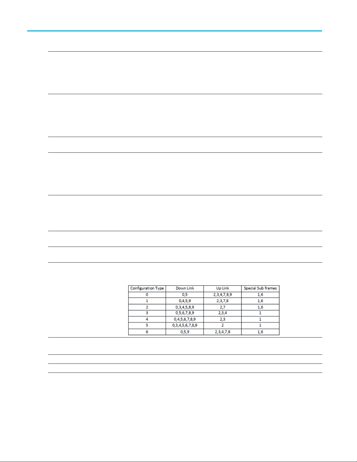
Duplexing Type
Configuration Configuration is available when the Duplexing Type is set to TDD.
ansmission
Tr
Carrier Aggregation
Additional Carriers Set the number of addition carriers to 1, 2 or 3.
Set the carrier bandwidth value to 1.4 MHz, 3 MHz, 5 MHz, 10 MHz, 15 MHz, or 20
MHz.
Set the Duplexing Type to TDD (time-division-duplexing) or FDD (frequency division
duplexing).
Choose a Configuration type from 0 to 6. See the following chart for specifics about
the various types.
ansmission is available when the Duplexing Type is set to FDD.
Tr
Set the Transmission to UpLink or DownLink.
32 Environment Printable Help Document
Page 41

Emitter advanced settings Noise emitter parameters
Item Description
Carrier BandWidth Set a Carrier BandWidth for each addition carrier.
r BandWidth to 1.4 MHz, 3 MHz, 5 MHz, 10 MHz, 15 MHz, or 20 MHz.
ffset for each addition carrier.
Carrier O ffse
xxx
Set the Carrie
t
Set a Carrier O
The carrier offset frequency range is determined by the selected Bandwidth.
Noise emitter parameters
Item Description
Noise
White Adds white noise.
Band Limited
Bandwidth
Duration
Full Scenario Duration Choose this option to match the noise signal duration to the final waveform duration.
User Defined Duration If you select this option, the Duration field becomes active.
xxx
Adds Band Limited noise. If you select this option, the Bandwidth field becomes active.
Available only if you choose Band Limited as the Noise type. Enter a value to specify
the bandwidth of the noise signal.
Enter a value to specify the duration, in seconds, of the noise signal.
OFDM emitter parameters
The O FDM emitter advanced parameters are divided into six tabs:
Frame Settings tab
mble tab
Prea
(see page 33)
(see page 34)
Header tab (see page 35)
Payload tab (see page 35)
Symbol tab (see page 36)
Hopping tab (see page 42)
Frame Settings tab
The Frames tab sets the bandwidth and off-time of the OFDM frame.
Environment Printable Help Document 33
Page 42

Emitter advanced settings Preamble tab
Item Description
Bandwidth
Off-Time Enter the amount of off-time to add to the end of the OFDM frame.
xxx
Enter the bandwidth of the carrier in Hz.
The bandwidth is dependent on the instrument type.
Preamble tab
Click Turn On to enable the frame preamble.
Enable one (or both) of the Preamble selections to define the path to a saved preamble file. You can enter
the path directly or use the folder icon to navigate to your saved file.
For each frame, you can use either or both preamble files. Based on the different standard needs, there can
be multiple preamble requirements. Two preambles are supported.
Item Description
ain
Dom
epeat
R
equency
Fr
me
Ti
Specify data in Frequency domain or Time domain.
Preamble data can be specified in the Frequency domain.
Preamble data can be specified in the Time domain.
Specify the repeat value, which defines the number of times Preamble is repeated.
34 Environment Printable Help Document
Page 43

Emitter advanced settings Header tab
Item Description
Subcarriers Spacing Subcarrier spacing defines the separation of each carrier in the frequency domain description
of the Preambl
Sampling Rate Specify the sa
xxx
e data.
mpling rate for the data in the Preamble file.
Header tab
Click Turn On to enable the header.
Item Description
File
Domain
Repeat
arriers
Subc
Spacing
Sampling Rate Specify the sampling rate for the data in the Header file.
Symbols Select S ymbols to insert defined symbols i nto the table.
Symbols Select a row to insert a user defined symbol. A dialog box is presented to allow you the select
Repeat
xxx
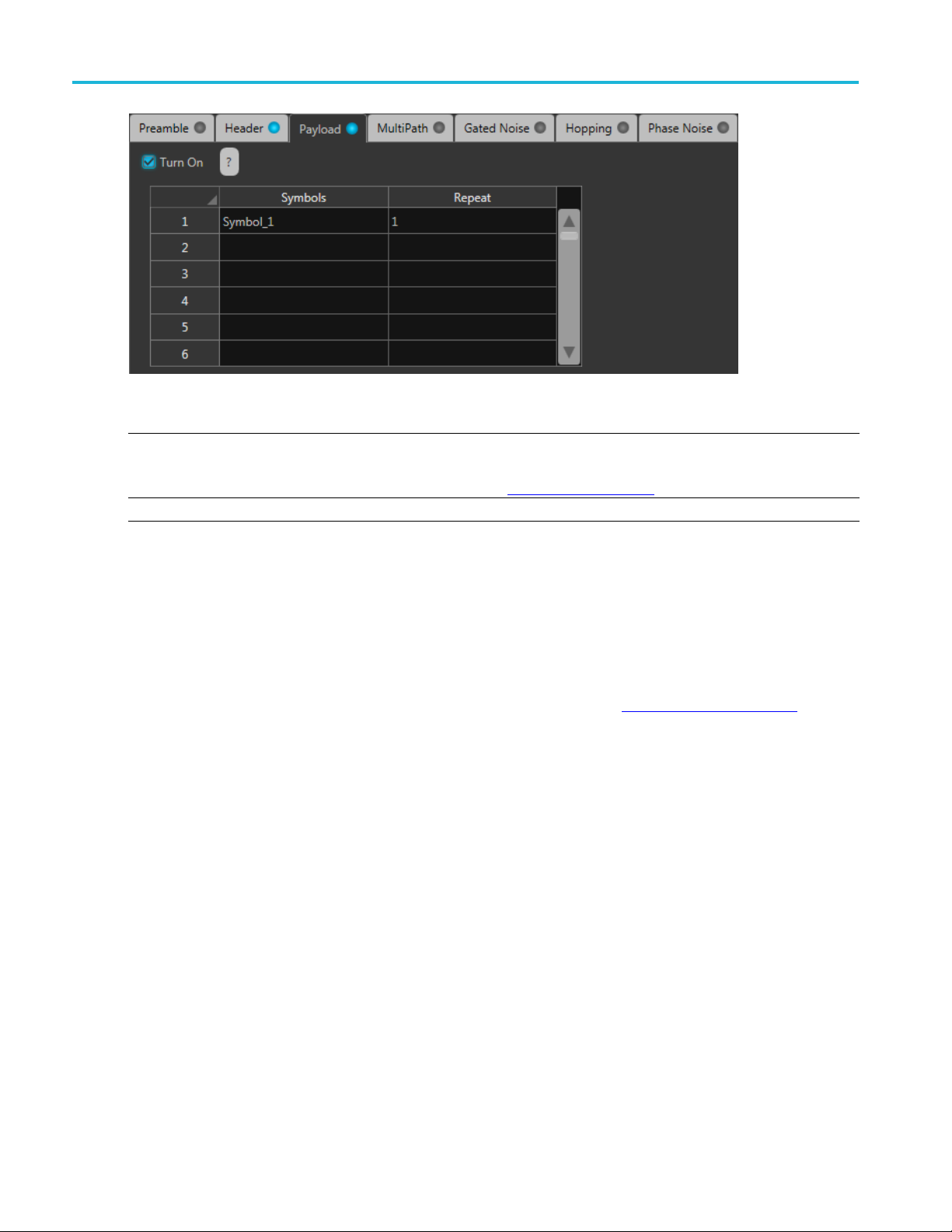
Payload tab
ClickTurnOntoenablethepayload.
Select file to use a predefined header file.
Chose how the header file is structured in the Frequency domain or Time domain.
ided spectrum is assumed for Frequency domain.
Two-s
fy the repeat value, which defines the number of times Header is repeated.
Speci
arrier spacing defines the separation of each carrier in the frequency domain description
Subc
of the Header data.
the symbol to insert.
e symbols must first be defined in the Symbol tab
Th
pecify the repeat value, which defines the number of times the symbol is repeated.
S
(see page 36).
Environment Printable Help Document 35
Page 44
Emitter advanced settings Symbol tab
Item Description
Symbols Select a row to insert a user defined symbol. A dialog box is presented to allow you the select
the symbol to insert.
(see page 36).
xxx
Repeat
The symbols must first be defined in the Symbol tab
Specify the repeat value, which defines the number of times the symbol is repeated.
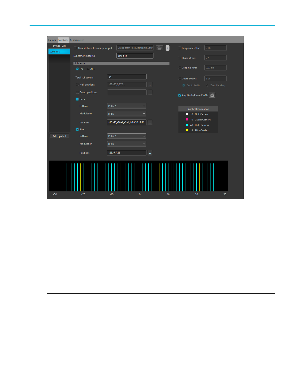
Symbol tab
Use the Symbol tab to create and define symbols. Each symbol is unique with different settings.
At least one symbol is present in the symbol tab. Click Add to add a symbol to the table. To rename a
symbol, select the symbol, double-click it and type a name.
The symbols defined here are then available for selection in the Frames Payload tab
(see page 35).
36 Environment Printable Help Document
Page 45
Emitter advanced settings Symbol tab
Item Description
User-defined
ency weight
frequ
arriers Spacing
Subc
Frequency Offset If enabled, then specify the frequency offset value for the selected symbol.
Phase Offset If enabled, then specify the phase offset value for the selected symbol.
Clipping Ratio If enabled, then specify the Clipping Ratio value for the selected symbol. Clipping Ratio is the
Specify the file from which to load symbol data. You still have to specify the Subcarrier spacing.
ionally, you can add Frequency Offset, Phase Offset, Clipping Ratio, Guard Interval, and an
Addit
Amplitude/Phase Profile to the symbol.
The Subcarrier parameter selections are disabled when using a user defined file.
sided spectrum is assumed for a frequency domain symbol description.
Atwo-
r the frequency interval between carriers.
Ente
The maximum value is dependent on carrier bandwidth (BW). Range is from 1 Hz to carrier
bandwidth.
1Hz
Min:
Max: Carrier BW value
Clip power level divided by Average Power.
Environment Printable Help Document 37
Page 46

Emitter advanced settings Subcarriers for symbols
Item Description
Guard Interval This is used to reduce inter-symbol interference and reducing fading due to the frequency selective
hannels.
to display the profile configuration display.
c Amplitude Phase Profile
rier section is not available when using a user-defined frequency weight.
(see page 38) for an explanation of the settings.
(see page 41).
Amplitude Phase
Profile
Subcarrie
xxx
r
nature of the c
Cyclic Prefix
Zero Padding
Select to turn on the profi le.
Use the settings icon
See the topi
The subcar
See the Subcarriers
Subcarriers for symbols
The subcarrier section is not available when using a user-defined frequency weight.
38 Environment Printable Help Document
Page 47

Emitter advanced settings Defining the Pattern
Item Description
–/+
All+
Total subcarriers
Null positions
Select –/+ to show both the negative and positive subcarriers in the display graph.
Select All+ to
Enter the numb
A minimum of two carriers is required.
A maximum of 4096 carries is allowed but the number must be a multiple of two.
Enable the Null positions if you want to specify certain subcarriers as null carriers, then specify the
positions.
Double click inside the positions box to enter values directly.
only show the positive subcarriers in the display graph.
er of carriers for each symbol.
Click the
Null carriers are colored white in the display graph.
See Defining subcarrier positions
positions.
Guard positions Enable Guard positions if you want to specify certain subcarri ers a s guard carriers, then specify
the positions.
Double click inside the positions box to enter values directly.
Click the
Guard carriers are colored fuchsia in the display graph.
See Defi
positions.
nd Pilot
Data a
subcarriers
ern
Patt
Modu
itions
Pos
xxx
lation
Enable Data and Pilot subcarriers to specify these subcarriers.
Data carriers are colored blue in the display graph.
carriers are colored yellow in the display graph.
Pilot
Once enabled, you can specify the Pattern, Modulation, and Positions.
Data and Pilot subcarriers require a pattern selection. See Defining the Pattern
Data and Pilot subcarriers require a modulation selection. See Modulation types
Data and Pilot subcarriers require that you specify the positions of these carriers.
See Defining subcarrier positions
sitions.
po
icon to display a text entry screen for easier entry.
(see page 41) for information on how to properly format the
icon to display a text entry screen for easier entry.
ning subcarrier positions
(see page 41) for information on how to properly format the
(see page 41) for information on how to properly format the
(see page 39).
(see page 40).
Defining the Pattern
tem
I
ll One
A
All Zero
File
Environment Printable Help Document 39
escription
D
ends a sequence of binary 1 symbols.
S
Sends a sequence of binary 0 symbols.
Select the base data file to be used by entering the path or browsing to the file. The supported
format is .txt.
Page 48

Emitter advanced settings PRBS Editor
Item Description
PRBS Select the PRBS type from the following: 7, 9, 15, 16, 20, 21, 23, 29, 31, and User Defined.
Pattern
xxx
PRBS Editor
This dialog box is displayed when clicking PRBS Editor icon when PRBS is set to User Defined for
the Data and Pilot pattern type. (Symbols tab).
PRBS sequences are generated by a feedback shift register. The number (#) following PRBS indicates the
length of the generating shift register. For instance, a shift register with 16 memory cells is required to
generate a PRBS 16 sequence. The pseudo-random sequence of a PRBS generator is determined by the
number of registers and the feedback.
To edit the bit
display the PRBS Editor
Enter a pattern of 0s and 1s up to a maximum of 256 digits in the text field that appears.
sequence, select User Defined. This displays the PRBS Editor icon
(see page 40) dialog screen.
. Select to
Modulation types available
Item Description
PSK BPSK, QPSK, 8PSK
QAM 8 QAM, 16 QAM, 32 QAM, 64 QAM, 128 QAM, 256 QAM, 512 QAM, 1024 QAM
xxx
40 Environment Printable Help Document
Page 49

Emitter advanced settings Defining subcarrier positions
Defining subcarrier positions
Null, Guard, Data, and Pilot positions all need to be specified when enabled.
Proper format of the positions must be followed to avoid errors.
Double click inside a positions box to enter values directly. Or, click the icon to display a text
entry scree
Separate all positions (or ranges) with a single comma.
Define a range of positions with the use of colon.
Example:
–22:–19,12,20 selects the four positions from –22 through –19, then positions 12 and 20.
n for easier entry.
Amplitude Phase Profile
This feature enables the you to selectively apply attenuation and phase rotation on each subcarrier or each
type of
subcarrier, such as pilot and data subcarriers.
Environment Printable Help Document 41
Page 50

Emitter advanced settings Hopping tab
Item Description
Fixed
Data
Pilot
Custom Selecting Custom enables the table editor.
xxx
Selecting Fixed a llows you to enter the amplitude and phase for all data and pilot positions.
The data subcarrier (in the Symbols tab) must be enabled before you can choose to set the
data phase pro
The pilot sub
phase profile.
With the custom table editor, you can specify the amplitude and phase for any carrier position.
See Defining
positions.
file.
carrier (in the Symbols tab) must be enabled before you can choose to set the Pilot
subcarrier positions
(see page 41) for information on how to properly format the
Hopping tab
Click Turn On to enable hopping.
Hopping a
llows you to add frequency and amplitude hopping for a selected carrier.
Frequency hopping can be used to create frequency agile waveforms. Frequency hopping is used in
nic counter measures by rapidly switching the frequency of the transmitted energy, and receiving
electro
only that frequency during the receiving time window.
Item Description
Hop Time Hopping times are based on the Frequency Hop List.
Select the method to define the Hop Time:
Symbol Start Index
Symbols Per Hop
Symbol Start
Index
Defines the index the specific hop starts. Each hop must contain a unique start index.
42 Environment Printable Help Document
Page 51

Emitter advanced settings P25 emitter parameters
Symbols Per Hop
Symbols per Ho
field
Repeat List
xxx
p
Symbols per Ho
the entire hop pattern.
Range: 1 to 5000000.
Frequency (not available for IQ signal format)
Relative Frequency
Amplitude
When the Repeat List is enabled, the relative frequency and amplitude offset values are repeated.
p determines how many Symbols occur between each Hop. The value applies to
P25 emitter parameters
Item Description
Standard Choose the P25 standard to create.
Modulation
xxx
Radar emitter parameters
Radar e mitter advanced parameters are divided into six tabs:
Pulse Envelope (see page 43)
Modulation (see page 45)
Staggered PRI (see page 55)
Offsets (see page 59)
Hopping (see page 60)
Antenna (see page 63)
Phase 1 or Phase 2.
For Phase 1, Modulation is fixedtoC4FM.
ase 2, Modulation can be set to either HCPM or HDQPSK.
For Ph
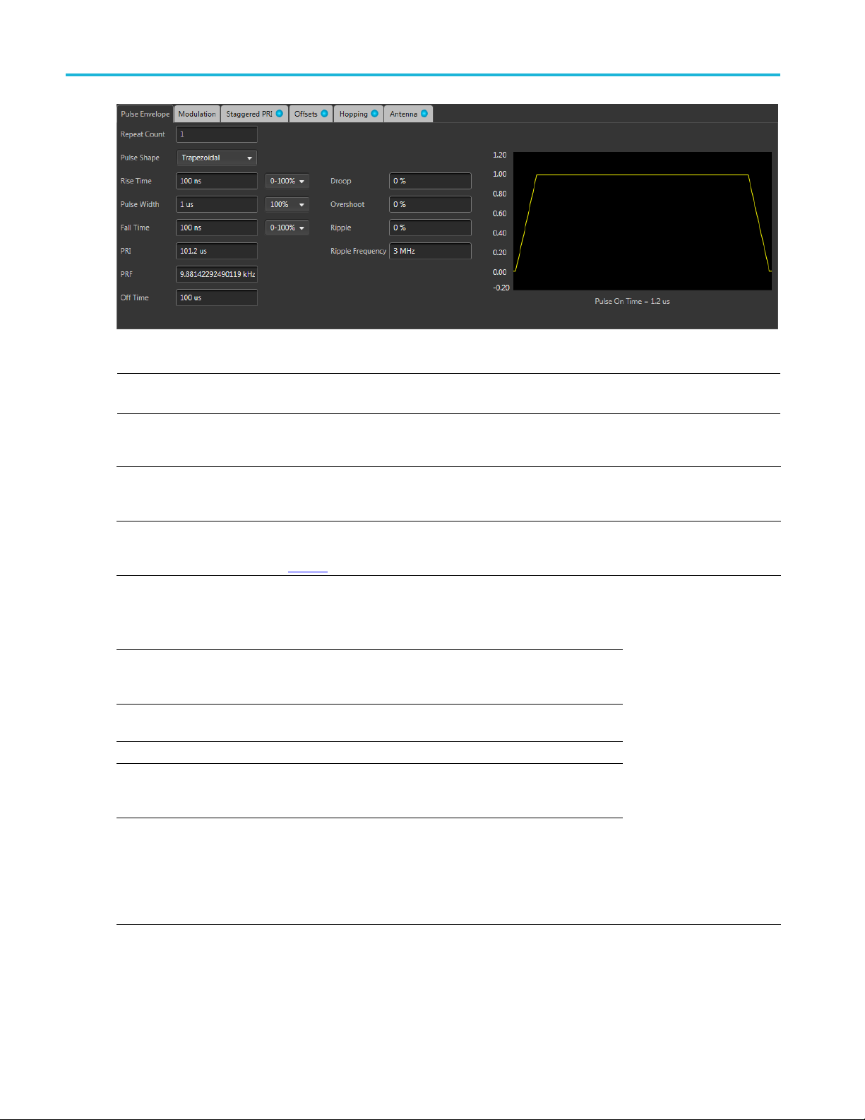
Pulse Envelope tab
Pulse Envelope parameters define the Pulse Shape, Rise Time, Pulse Width, Fall Time, and Off Time.
Environment Printable Help Document 43
Page 52
Emitter advanced settings Pulse Envelope tab
NOTE. The available Pulse Envelope parameters depend on the selected pulse shape. Not all parameters
are available for all pulse shapes.
Item Description Range, Default value
Repeat Count Enter the number of times to repeat the pulse. The PRI of the
pulse does not increase, but the Configured Duration for the
radar emitter increases to match the PRI × Repeat Count.
Pulse Shape Select the pulse shape from the following: Rectangular,
Trapezoidal, Raised Cosine, Exponential, Saw tooth, Gaussian,
and Custom
Rise Time
Fall Time
Pulse Width
Off Time (dead time) Enter the o ff tim e after the fall time.
Sampling Rate Available only when the pulse shape is Custom. Enter the
PRI
Enter the rise time for the pulse. Define the rise time between
0–100%, 10–90% or 20–80% of the voltage level.
Available only for Trapezoidal, Raised Cosine, Exponential, and
Saw Tooth pulse shapes.
Enter the fall time for the pulse. Define the fall time between
0–100%, 10–90% or 20–80% of the voltage level. Available for
all pulse shapes except Saw Tooth, Gaussian, and Custom.
Enter the pulse width. Define the width at 50% or 100% voltage.
Available for all pulse shapes except Saw Tooth and Custom.
sampling rate at which the custom pulse has been generated in
kHz, MHz, GHz, or Hz.
The Pulse Repetition Interval (PRI) value is automatically
generated based on the pulse envelope parameters and is
displayed as seconds. The PRI value is updated whenever the
values of any of the pulse envelope parameters are changed.
Changing the PRI updates the off time without changing the
other parameters of the pulse.
.
Trapezoidal
The range depends on the
instrument and options
installed.
The default values
change based on the
pulse shape.
44 Environment Printable Help Document
Page 53

Emitter advanced settings Modulation tab
Item Description Range, Default
PRF
Droop
Overshoot Enter the ov
Ripple
Ripple Fr
xxx
equency
The Pulse Repe
is automatically generated based on the pulse envelope
parameters.
ThePRFvaluei
pulse envelope parameters are changed.
Enter the droop in percentage of voltage.
Available for all pulse shapes except Saw Tooth, Gaussian, and
Custom.
Available for all pulse shapes except Saw Tooth, Gaussian, and
Custom.
Enter the ripple in percentage of voltage.
e for all pulse shapes except Saw Tooth, Gaussian, and
Availabl
Custom.
Enter the ripple frequency in H z, kHz, MHz, or GHz.
Available for all pulse shapes except Saw Tooth, Gaussian, and
Custom.
tition Frequency (PRF) is 1/PRI and the value
s updated whenever the values of any of the
ershoot in percentage of voltage.
NA
0 to 50%, 0
0 to 50%, 0
0 to 50%, 0
Based on t
and the options installed,
3MHz
value
he instrument
Create a custom pulse
Selecting Custom from the pulse Shape menu allows you to define a custom pulse shape. The custom file
must meet the following conditions:
Input files are ASCII files(.txt)orMATLABfiles (.mat).
Only positive numbers are allowed. All other characters are invalid (including tab and space). The
application stops reading data when it encounters invalid data.
The maximum length of the file is 1M samples.
In ca se of an ASCII file, the data should be in floating point and the values should be arranged in a
single column and several rows with one value in each row.
Thevariablenameinthe.matfile should be "SamplePoints". The .mat file should be saved with
the v7.3 option.
Here is an example of MATLAB command for saving a file: save('SamplePulseEnvelope.mat','SamplePoints', '-v7.3');
A MATLAB file should contain a variable with ‘n’ sample points or values of the format 1 x n or
n x 1. For example,
SamplePoints = [ 0.5 0.3 0.2 0.7 ….]
Modulation tab
The Modulation tab allows you to provide different modulation schemes that can be applied to the pulse
width for a selected pulse.
Environment Printable Help Document 45
Page 54

Emitter advanced settings Modulation tab
The available modulation schemes are shown in the following table. See the links in the following table
to view detailed information about these modulation types. You can also view the Modulation Settings
(see page 46) top
ic.
NOTE. The No Modulation setting is the same as continuous modulation. No Modulation is the default
setting.
Modulation category Modulation type
No modulati
Frequency
Phase
igital Modulation
D
Custom Modulation You can select a custom pulse shape file from a directory.
xxx
on
Linear fre
Chirp Sequ
Up-Down C
Piece-wise LFM
Step Frequency
User Defined Step FM AM
Non Linear FM
Barker Code
Frank Code
Polyphase Codes
P1 Polyphase Codes
P2 Polyphase Codes
P3 Polyphase Codes
P4 Polyphase Codes
User Defined Step P M AM
BPSK
QPSK
quency modulation (LFM)
ence
hirp
Modulation s ettings
Linear Frequency Modulation (LFM)
In LFM or Chirp Modulation, the frequency is swept linearly across the pulse width. The sweep can
be Low to High (upward) or High to Low (downward). LFM is used to achieve higher bandwidths in
pulse compression RADARS.
Table 1: Linear frequency modulation parameters
Selection
Sweep Range Enter the sweep range in Hz, kHz, MHz, or GHz.
Frequency Sweep Enter the frequency sweep: High to Low, or Low to High.
xxx
46 Environment Printable Help Document
Description
Range, default value
Range is dependent on
the instrument, 10 MHz
Low to High
Page 55

Emitter advanced settings Modulation tab
Chirp Sequence Modulation
Chirp Sequence modulation allows you to define multiple LFMs. This modulation is mainly used in
automobile RADAR.
Table 2: Chirp Sequence parameters
Selection
Sweep Range Enter the sweep range in Hz, kHz, MHz, or GHz.
Description
Range, default value
Range is dependent on
the instrument, 10 MHz
Frequency Sweep Enter the frequency sweep: High to Low, or Low to High.
Number of chirps Enter the number of chirps in the modulation.
xxx
Low to High
1 to 100, 4
Up-Down Chirp Modulation
Up-Down Chirp modulation varies the frequency of the carrier from –Sweep Range/2 to +SweepRange/2
and then again from +Sweep Range/2 to –Sweep Range/2.
Table 3: Up-down chirp modulation parameters
Selection
Sweep Range Enter the sweep range in Hz, kHz, MHz, or GHz.
Number of Up-Downs Enter the number of peaks (ups) and troughs (downs) in the
ert
Inv
xxx
Description
ation.
modul
If the number of Up-downs = 1, then the pulse width is divided
into two. The first half of the pulse will have l inear chirp from
ep/2 to +Sweep/2 and the second half of the pulse will
–Swe
have linear chirp from +Sweep/2 to –Sweep/2.
If the number of Up-downs is greater than 1 (n>1), then the
lation shall create multiple (n) number of ‘V’s or Inverted
modu
‘V’s. T he subpulse width of each V is equal to PulseWidth/n.
Check the box to create Down-Up chirp, which creates a ‘V’
shaped frequency profile.
en unchecked, an inverted ‘V’ shaped frequency profile is
Wh
created.
Range, default value
Range is dependent on
the instrument, 10 MHz
1to12,1
hecked
Unc
Piecewise LFM Modulation
Piecewise LFM modulation allows you to define LFM for each subpulse.
Environment Printable Help Document 47
Page 56

Emitter advanced settings Modulation tab
Table 4: Piecewise LFM parameters
Selection
Initial Offse
t
Add steps button
Description
Enter the init
Enter the num
ial offset in Hz, kHz, MHz, or G Hz .
ber of steps to add and then click the Add button.
Range, default
Range is dependent on
the instrumen
1to10,1
value
t, 10 MH z
The added step(s) will appear in the table.
If there are no entries in the table and the Add button is clicked,
then the dura
tion of each sub pulse = pulse width / number of
steps.
Table setti
Duration (
ngs:
s)
Enter the d
uration of the subpulse width in s.
Cannot be g
reater than
the pulse On Time
Duration (%)
Automatic
ally calculated based on the pulse width and the
N/A
duration of the subpulse.
Sweep Range Enter the sweep range in Hz, kHz, MHz, or GHz.
Range is d
ependent on
the instrument, 10 MHz
Frequency Sweep Enter the frequency sweep: High to Low, or Low to High.
xxx
Low to Hig
h
Step Frequency Modulation
Step Frequency modulation allows you to divide the pulse width to equal subpulses and to assign different
frequencies to each subpulse.
Table 5: Step Frequency parameters
Selection
Step Count Enter the number of steps.
Initial Offset Enter the initial offset in Hz, kHz, MHz, or GHz.
Frequency Offset Enter the frequency offset in Hz, kHz, MHz, or GHz.
Ramp Function
Ramp Duration (%)
xxx
Description
Select Linear or Cosine to set how the transition from one
subpulse to another occurs.
Enter the desired ramp duration.
Range, default value
1 to 200, 4
Range is dependent on
the instrument, 10 MHz
Range is dependent on
the instrument, 10 MHz
Linear
Up to 100%, 0%
User-defined Step FM AM Modulation
User Defined Step FM AM modulation allows you to define the number of subpulses and to set frequency
offset and amplitude values for each subpulse.
Table 6: User-defined Step FM AM parameters
Selection
Ramp Function
Ramp Duration
Description
Select Linear or Cosine to set how the transition from one
Range, default value
Linear
subpulse to another occurs.
Enter the desired ramp duration (%). Up to 100%, 0%
48 Environment Printable Help Document
Page 57

Emitter advanced settings Modulation tab
Selection
Add steps button
Table settin
Duration (s
Duration (%) Automatically calculated based on the pulse On Time and the
Frequency O ffset Enter the frequency offset in Hz for the subpulse.
Amplitude (dB) Enter the amplitude in dB for the subpulse.
xxx
gs:
)
Description
Enter the numb
The added step(s) will appear in the table.
If there are no entries in the table and the Add button is clicked,
then the durat
steps.
Enter the du
duration of the subpulse.
er of steps to add and then click the Add button.
ion of each sub pulse = pulse width / number of
ration of the subpulse width in s.
Range, default
1to10,1
Cannot be gr
the pulse On Time
N/A
Range is dependent on
the instrument, 10 MHz
-100 dB to 0 dB, 0 dB
value
eater than
NOTE. Duration in percentage is calculated automatically up to three decimal places. This can cause
rounding of the actual duration entered.
Nonlinear Frequency Modulation
Nonlinear FM can be used to define a frequency modulation that can have a nonlinear profile, unlike
with Linear FM.
Nonlinear FM uses the coefficients to create the instantaneous frequencies for modulation. F(t) =
2*pi*C(t)*t, where C(t) is the instantaneous frequency
Instantaneous frequency C(t) can be defined b y the following polynomial:
C(t) = c0+c1*t+c2*t*t +c3*t*t*t..., where c0, c1, and c2 and others are the coefficients with order 0,
1, 2, and others.
Curves can be defined/drawn (curve fitting) with polynomials. In the following, a
and a0are the
n
coefficients.
Y(t) = a
*xn+a
n
n-1
*x
n-1
+a
n-2
*x
n-2
+ ....+ a
0
The equation is based on what the you want to fit. Examples are available in Radar books for different
types of nonlinear profiles.
Nonlinear FM profiles. When Nonlinear FM is the chosen Modulation, you can select from the following
three profiles. When one of the Taylor Weighted profiles is selected, a control for Bandwidth is also
available. When User Defined Coefficients is selected, click on t he folder icon that appears to provide
a file path.
Taylor Weighted Non symmetrical (default)
Taylor Weighted Symmetrical
User Defined Coefficients
Environment Printable Help Document 49
Page 58

Emitter advanced settings Modulation tab
Taylor Weighted Nonlinear FM signals are created using the following equation:
Where
BW = bandwidth
PW = pulse on
K
=–0.1145
1
= 0.0396
K
2
= –0.0202
K
3
=0.0118
K
4
= 0.0082
K
5
K
K
055
=0.0
6
= –0.0040
7
time
User defined coefficients file requirements. AUserdefined coefficients file must meet the following
conditions:
Input files are ASCII files(.txt)orMATLAB(.mat).
aximum length of the file is 100 coefficients.
The m
When ASCII file is chosen, the data should be in fl oating point format and the values should be
anged in a single column and several rows with one value in each row.
arr
Thevariablenameinthe.matfile should be "NLFMCoefficients". The .mat file should be saved
th the v7.3 option.
wi
Here is an example of MATLAB command for saving a file: save('Coefficients.mat','NLFMCoeffi-
ients', '-v7.3');
c
A MATLAB file should contain a variable with ‘n’ coefficients or values of the format 1 x n or n x
. For example,
1
NLFMCoefficients=[0.50.30.20.7….]
Barker Code
With the Barker Code (a bi-phase coded pulse), the phase is switched between 0 and 180 degrees. The
number of subpulses is defined by the Barker Code number. For example, Barker 11 has eleven subpulses.
The Barker codes are predefined.
50 Environment Printable Help Document
Page 59

Emitter advanced settings Modulation tab
Table 7: Barker code parameters
Selection
Description
Code Length Enter the leng
th of the Barker code. The options are: 2, 3, 4,
Range, default
2
value
5, 7, 11, and 13.
xxx
Frank Code
Frank Code is a type of Polyphase code where the pulse width is divided into subpulses and the phase of
the subpulse is changed.
The phase value for each subpulse changes based on the following formula, where subpulse = Code Length
* Code Length and p=0, 1, 2,…..code length–1 and q=0, 1, 2…code length–1.
Phase(p,q) = 2*pi*p*q/Code length
Table 8: Frank code parameter
Selection
Code Length Enter the length of the code.
xxx
Description
Range, default value
1to10,1
Polyphase Codes
Polyphase codes are a type of phase-coded pulse waveform.
Table 9: Polyphase codes parameters
Selection
Number of Steps Enter the number of phase entries.
Description
Range, default value
1 to 200, 4
Initial Offset Enter the initial offset in degrees. –180° to +180°, 45°
Phase Offset Enter the phase offset in degrees. –180° to +180°, 90°
Ramp Function
Select Linear or Cosine to set how the transition from one
Linear
subpulse to another occurs.
Ramp Duration
xxx
Enter the desired ramp duration (%). Up to 100%, 0%
P1 Polyphase Code
P1 Polyphase code is a type of Polyphase code.
Table 10: P1 polyphase code parameter
Selection
Code Length Enter the length of the code.
xxx
Description
Range, default value
1to10,1
The phase for each of the subpulses is derived as follows:
Phase(p,q) = –180/Codelength*(Codelength–(2*p–1))*[(p–1)*Codelength)+(q–1))]; where p=1, 2…code
length and q=1, 2, …code length
Where:
Environment Printable Help Document 51
Page 60

Emitter advanced settings Modulation tab
Number of subpulses = Codelength * Codelength
P2 Polyphase Code
P2 Polyphase code is a type of Polyphase code.
Table 11: P2 polyphase code parameter
Selection
Code Length Enter the length of the code.
xxx
Description
Range, default value
1to10,1
The phase for each of the subpulses is derived as follows:
Phase(p,q)=[((90/Codelength )*((Codelength –1)/ Codelength))–((180/ Codelength)*(p–1))]*[
Codelength+1–(2*q)] ; where p=1, 2 , … code length and q=1, 2, .. code length
Where:
Number of subpulses = Codelength * Codelength
P3 Polyphase Code
P3 Polyphase code is a type of Polyphase code.
Table 12: P3 polyphase code parameter
Selection
Code Length Enter the length of the code.
xxx
Description
Range, default value
1 to 100, 1
The phase for each of the subpulses is derived as follows:
Phase(p)=(180*(p–1)*(p-1))/ code length; where p=1, 2, …..Codelength
Where:
Number of subpulses = Codelength
P4 Polyphase Code
P4 Polyphase code is a type of Polyphase code.
Table 13: P4 polyphase code parameter
Selection
Code Length Enter the length of the code.
xxx
Description
The phase for each of the subpulses is derived as follows:
e(p)=[180*(p–1)2/ code length]–[180*(p–1)]
Phas
Where:
Number of subpulses = Codelength
User Defined Step PM AM
Range, default value
1 to 100, 1
52 Environment Printable Help Document
Page 61

Emitter advanced settings Modulation tab
User DefinedStepPMAMallowsyoutodefine the number of subpulses and phase and amplitude values
for each subpulse.
Table 14: User-defined step PM AM parameters
Selection
Ramp Function
Ramp Duration
Add step button
Duration (s) Enter the duration of the subpulse width. Cannot be greater than
Duration (%) Automatically calculated based on the pulse On Time and the
Phase Offset (
Amplitude (d
xxx
deg)
B)
Description
Select Linear or Cosine to set how the transition from one
subpulse to anothe
Enter the desired r
Enter the number o
The added step(s) will appear in the table.
If there are no entries in the table and the Add button is clicked,
then the duratio
steps.
duration of th
Enter the phas
Enter the amp
r occurs.
amp duration (%).
f steps to add and then click the Add button.
n of each sub pulse = pulse width / number of
e subpulse.
e offset in degrees for the subpulse.
litude in dB for the subpulse.
Range, default value
Linear
Up to 100%, 0%
1to10,1
the pulse On Time
N/A
–180° to +180°
-60dBto0dB,0dB
, 90°
NOTE. Duration in percentage is calculated automatically up to three decimal places. This can cause
rounding of the actual duration entered.
BPSK and QPSK Modulation
Enter the number of symbols for the pulse. Check the option “Use same symbols for all pulses” to have
the same number of symbols for all the pulses in the pulse group.
Item Description
Modulation
Number of Symbols Enter the number of symbols in the pulse.
Use same sym
Data
Pattern
All Zero
All One Sends a sequence of binary 1 symbols.
bols for all pulses
Select the data source:
Sends a sequence of binary 0 symbols.
Select BPSK or QPSK.
Range: 1 to 200
Default: 4
Check (enab
This option is available only when the Repeat parameter (in the Pulse Train table for
the selected Pulse Group) is greater than 1.
Default: Un
le) to use the same number of symbols for all the pulses in the modulation.
checked
Environment Printable Help Document 53
Page 62

Emitter advanced settings Modulation tab
Data
PRBS Select the PRBS type from the following: 7, 9, 15, 16, 20, 21, 23, 29, 31, and User Defined.
Pattern
File
Filter
Filter
Alpha
Pre/Post
xxx
Pattern
To edit the bit
display the PRBS Editor
Enter a pattern of 0s and 1s up to a maximum of 80 digits in the text field that appears.
Select the base data file to be used by entering the path or browsing to the file. The supported
formats are .txt.
Select the filter from the following options: Rectangular, Raised Cosine, and Root Raised Cosine.
Specify a value for the alpha factor.
Range: 0 to 1
Default: 0
Set the bi
Zeros, or Pattern.
sequence, select User Defined. This displays the PRBS Editor icon
(see page 55) dialog screen.
.35
t pattern for the initial (pre) and final (post) values of the filter. Select Wrap Around,
. Select to
Custom Modulation
Custom modulation allows you to specify a custom pulse modulation using an external file of the
MATLAB format or .txt format. This file should contain Time versus Phase values in the specified format.
Phase values should be in degrees.
A custom modulation file must meet the following conditions:
Input files are ASCII files(.txt)orMATLAB(.mat).
Both positive and negative numbers are allowed. All other characters are invalid (including tab and
space). The application stops reading data when it encounters invalid data.
The maximum length of the file is 1M samples.
When ASCII file is chosen, the data should be in fl oating point format and the values should be
arranged in a single column and several rows with one value in each row.
Thevariablenameinthe.matfile should be "CustomPhaseProfile". The .mat file should be saved
with the v7.3 option.
Here is an example of MATLAB command for saving a file: save('SamplePhaseProfile.mat','CustomPhaseProfile', '-v7.3');
A MATLAB file should contain a variable with ‘n’ phase points or values of the format 1 x n or
n x 1. For example,
54 Environment Printable Help Document
Page 63

Emitter advanced settings PRBS Editor
CustomPhaseProfile = [ 0.5 0.3 0.2 0.7 ….]
PRBS Editor
The Hopping tab and the Modulation tab both provide access to this dialog box when User Defined is
selected as t
this dialog box.
PRBS sequences are generated by a feedback shift register. The number (#) following PRBS indicates the
length of the generating shift register. For instance, a shift register with 16 memory cells is required to
generate a PRBS 16 sequence. The pseudo-random sequence of a PRBS generator is determined by the
number of registers and the feedback.
he PRBS Pattern. Clicking on the icon that appears next to the PRBS Pattern setting opens
Staggered PRI tab
Use the Staggered PRI tab to create multiple pulse repetition intervals and define pulse-to-pulse staggering.
Environment Printable Help Document 55
Page 64

Emitter advanced settings Staggered PRI tab
Follow these steps to specify multiple PRIs for a pulse group:
1. Check the Turn On box to enable and access parameter settings. Default setting is off (unchecked).
2. Set the following parameters for the selected p ulse.
Table 15: PRI/PRF parameters
Item Descriptio
Deviation Type
Ramp
File
Select fro
Select the
Default is U p.
The Ramp deviation type is:
Click the folder icon to select a file path to an ASCII file (.txt) or MATLAB (.mat)
rmat. Files must meet the conditions described in the File format conditions
file fo
(see page 58) topic below.
The File deviation type is:
n
m R amp, File, and Table.
Slope type (Up, Down, Up Down, Down Up).
Range, defa
Ramp
ult value
56 Environment Printable Help Document
Page 65

Emitter advanced settings Staggered PRI tab
Table 15: PRI/PRF parameters (cont.)
Item Description Range, default value
Table
Enter the PRI deviation for each pulse group in the table.
Right-click on the blank area in the table to access the menu to add and remove
items in the table.
Right-click on the deviation value cell access the menu to set deviation.
Slope Type (degrees)
(Available only w hen the R amp is the
selected deviation type.)
Min Deviation (ΔT)
The table deviation type is:
Enter the deviation slope in degrees or as the minimum deviation.
Slope = ΔT/PRI = tan(angle) = Peak Deviation/ (Repeat*PRI)
Peak Deviation = Repeat * ΔT
Deviation slope as the minimum
deviation.
0toPRI,0s
Environment Printable Help Document 57
Page 66

Emitter advanced settings Staggered PRI tab
Table 15: PRI/PRF parameters (cont.)
Item Description Range, default value
Degrees Deviation slope in degrees.
Repeat deviation pattern
(Available only when File or Table is
the selected deviation type.)
xxx
When checked, the application
repeats the PRI deviation values for
all the pulses. When unchecked, PRI
deviation values are used for only
those pulses and 0 is used for the
number of deviations listed in the file.
–180° to +180°, 0°
Unchecked
NOTE. If the Deviation Type is Ramp, the deviation ΔT is calculated as follows:
ΔT=(y*PRI*(i-1)), where y=tan(slope) in radians and i=1 to Repeat value
3. If you have selected Table, right-click and select Add to add a row to the table. Edit the deviation
values directly in the table. The number of rows in the table is limited to the value in the Repeat
pulse envelope parameter
File format conditions
A staggered PRI deviation file must meet the following conditions:
Input files are ASCII files(.txt)orMATLAB(.mat).
Both positive and negative numbers are allowed. All other characters are invalid (including tab and
space). The application stops reading data when it encounters invalid data.
The maximum length of the file is 1M samples.
When ASCII file is chosen, the data should be in fl oating point format and the values should be
arranged in a single column and several rows with one value in each row.
Thevariablenameinthe.matfile should be "StaggeredPRIDeviations". The .mat file should be
saved with the v7.3 option.
Here is an example of MATLAB command for saving a file: save('SamplePRIDeviations.mat','StaggeredPRIDeviations', '-v7.3');
A MATLAB file should contain a variable with ‘n’ deviations or values of the format 1 x n or n x
1. For example,
58 Environment Printable Help Document
Page 67
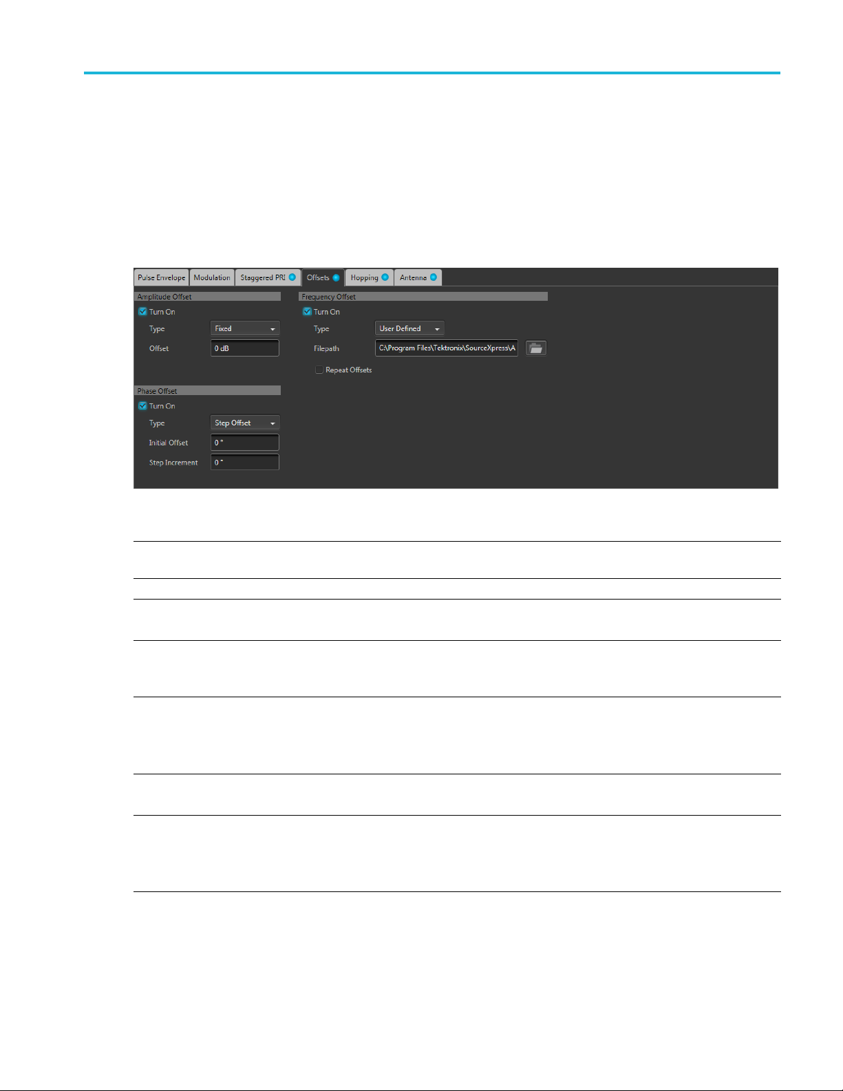
Emitter advanced settings Offsets tab
StaggeredPRIDeviations = [ 0.5 0.3 0.2 0.7 ….]
Offsets tab
This tab allows you to set Amplitude, Frequency, and Phase offset from pulse to pulse. Amplitude hopping
can be used to create different swirling models. Frequency and Phase offsets can be used to create
Frequency and Phase agile signals used in EW countermeasures.
Item Description
Turn On Check a box to activate the associated offset. You can select Amplitude Offset, Phase Offset,
and Frequency Offset.
Type
Choose Fixed, Step Offset, or User Defined as the offset type.
Offset This setting is available when Fixed is the selected offset type.
Set the offset in H z (for Frequency), dB (for Amplitude), or degrees (for Phase). Default setting is 0.
Initial Offset This setting is available when Step Offset is the selected offset type.
Set the initial offset in Hz (for Frequency), dB (for Amplitude), or degrees (for phase). Default
setting is 0.
Step Increment This setting is available when Step Offset is the selected offset type.
The step increments sets the offset to the pulses in the pulse group if the repeat is more than 1.
Set the step increment in Hz (for Frequency), dB (for Amplitude), or degrees (for phase). Default
setting is 0.
File Path
This setting is available when User Defined is the selected offset type.
Select a file to apply as frequency, phase, or amplitude offset.
Repeat Offsets Check the box to repeat offsets. Default setting is unchecked (off).
If the P ulse Group has a greater repeat count than the offsets listed in the file, then checking this
option repeats the offsets in the file for the rest of the pulses.
This selection only applies when User Defined is the selected offset type.
x
xx
Environment Printable Help Document 59
Page 68

Emitter advanced settings Hopping tab
File format conditions
A deviation file must meet the following conditions:
Input files are ASCII files(.txt)orMATLAB(.mat).
Both positive and negative numbers are allowed. All other characters are invalid (including tab and
space). The application stops reading data when it encounters invalid data.
The maximum length of the file is 1M samples.
When ASCII fi
arranged in a single c olumn and several rows with one value in each row. The values are frequency
values in Hz for Frequency Offset, in dB for Amplitude Offset, and in degrees for Phase Offset.
The .mat fileshouldbesavedwiththev7.3option.Thevariablenameinthe.matfile should be:
"Amplitu
"FrequencyOffsets" for Frequency Offset fi le.
"PhaseOffsets" for Phase Offset file.
Here is an example of MATLAB command for saving a file: save('SampleOffsets.mat','AmplitudeOffsets', '-v7.3');
A MATLAB file should contain a variable with ‘n’ sample points or values of the format 1 x n or
n x 1. For example,
PhaseOffsets = [ 0.5 0.3 0.2 0.7 ….]
Hopping tab
This tab allows you to define the hopping pattern from pulse-to-pulse. You can provide frequency offset
d amplitude deviation.
an
le is chosen, the data should be in floating point format and the values should be
deOffsets" for Amplitude Offset file.
Frequency hopping can used to create frequency agile waveforms. Frequency is changed from one pulse
another pulse. Frequency hopping is used in electronic counter m easures by rapidly switching the
to
frequency of the transmitted energy, and receiving only that frequency during the receiving time window.
mplitude hopping can be used to create different amplitudes from one pulse to another. Amplitude
A
hopping can be used to create different swirling models.
60 Environment Printable Help Document
Page 69
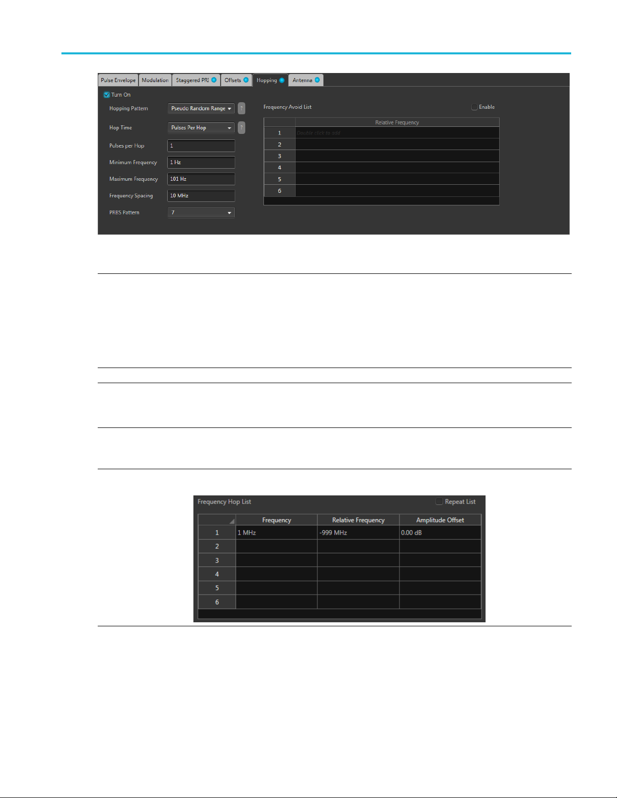
Emitter advanced settings Hopping tab
Item Descripti
Hopping Pattern Three hopping patterns are available.
Custom: Ho
Pseudo Random List: Hops are chosen randomly (based on PRBS selection) from the Frequency
Hop List.
Pseudo Ra
between a minimum and maximum frequency with a minimum frequency spacing. Frequencies
included in the Frequency Avoid List will be skipped.
Custom Hopping Pattern
Hop Time
Pulses
Per Hop
Select the method to define the Hop Time
Pulses
entire hop list.
Range: 1 to 5000000.
Use the Frequency Hop List.
on
ps are based on the F requency Hop List.
ndom Range: Hops are chosen randomly (based on PRBS selection) from frequencies
Pulses P
Pulse Start Index
er Hop
per Hop determines how many Pulses occur between each Hop. The v alue applies to the
Environment Printable Help Document 61
Page 70
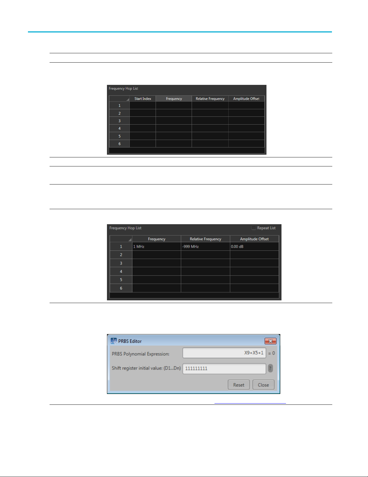
Emitter advanced settings Hopping tab
Custom Hopping
Pulse Start In
Pseudo Random List Hopping Pattern
Hop Time
Pulses Per Hop Pulses per Hop determines how many Pulses occur between each Hop. The value applies to
Pattern
dex
Defines the ind
Use the Freque
frequency.
Select the method to define the H op Time
Pulses Per Hop
the entire hop pattern.
Range: 1 to 5000000.
Use the Frequency Hop List.
ex the s pecifi c hop starts. Each hop must contain a unique start index.
ncy Hop List. Each index indicates the pulse that needs to hop to the specified
PRBS Pattern Select the PRBS pattern for hopping.
When User Defined is selected, a settings icon appears that allows you to open the PRBS Editor to
r a pattern.
ente
You can read more about the PRBS Editor in the PRBS Editor topic (see page 55).
62 Environment Printable Help Document
Page 71
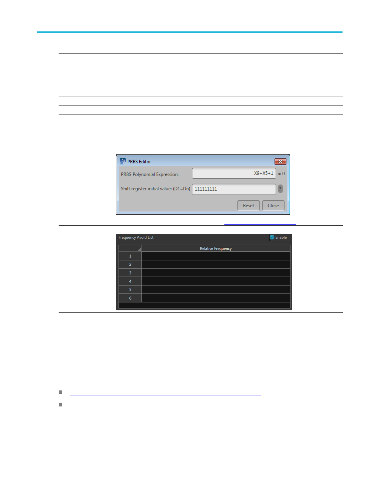
Emitter advanced settings Antenna tab
Pseudo Random Range Hopping Pattern
Hop Time
Pulses Per Hop Pulses per Hop determines how many Pulses occur between each Hop. The value applies to
Minimum Freq
Maximum Fre
Frequency Spacing Specify the minimum frequency intervals for hopping. The signal will hop avoiding the frequencies
PRBS Pattern Select the PRBS pattern for hopping.
uency
quency
Select the method to define the Hop Time
Pulses Per Hop
the entire hop
Range: 1 to 5000000.
Enter the frequency range within which to hop. Specify the start frequency for the range.
Specify the end frequency for the range.
specified in the table in this interval or at multiples of this interval.
When User
enter a pattern.
pattern.
Defined is selected, a settings icon appears that allows you to open the PRBS Editor to
Frequency Avoid List
xxx
Antenna tab
This tab allows you to apply Circular and Custom antenna scan types to the selected Pulse Group. The
ettings associated with each scan type are described below.
s
Quick links:
Antenna settings when Circular is the selected Scan Type (see page 64)
You can
Enabl
read more about the PRBS Editor in the PRBS Editor topic
e the Avoid List and the signal will avoid hopping in the frequencies specified in the table.
(see page 55).
Antenna settings when Custom is the selected Scan Type (see page 65)
Environment Printable Help Document 63
Page 72
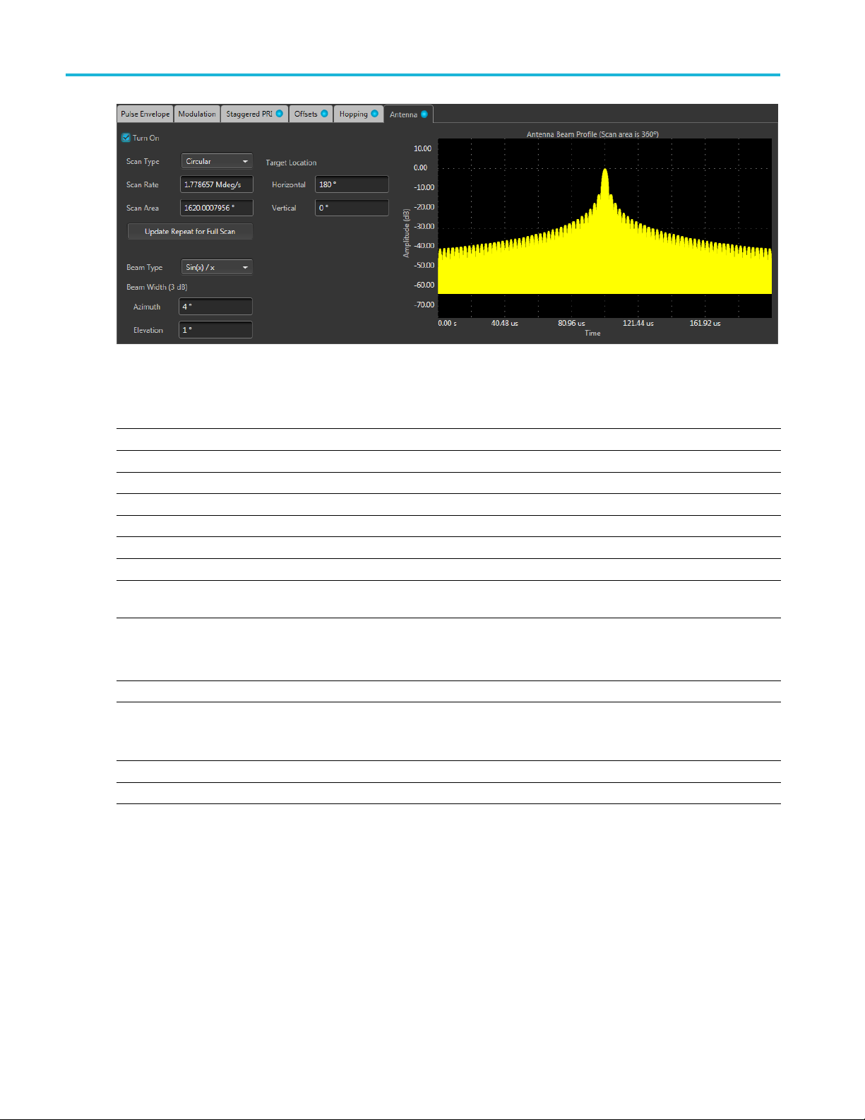
Emitter advanced settings Antenna tab
Antenna settings when Circular is the selected Scan Type
Item Description
Turn On Check box to apply antenna settings to the pulse train.
Scan Type Choose Circular or Custom scan to apply.
Scan Rate Enter the rate at which the scan takes place (degrees/second).
Scan Area Enter the scanned area (degrees).
Target Location
Horizontal
Vertical
Update Repeat for
can
Full S
Beam Type
Beam Width (3 dB)
Azimuth
evation
El
Show Plot Displays the antenna beam profile on an Amplitude vs Time graph.
xxx
Shows the following coordinates of the target.
Enter the horizontal location of the target (degrees).
Enter the vertical location of the target (degrees).
Click to update the pulse repeat count for one full scan.
t from the following beam types:
Selec
Sin(x)/x
Gaussian
Shows the compass direction of the antenna (azimuth). You can force the azimuth by entering a
ue.
val
Range: 0° to 360°
Shows the elevation of the antenna in degrees. You can force the elevation by entering a value.
64 Environment Printable Help Document
Page 73

Emitter advanced settings Antenna tab
Antenna s ettings when Custom is the selected Scan Type
Item Description
Turn On Check box to apply antenna settings to the pulse train.
Scan Type Choose Gaussian or Circular scan to apply to the pulse train.
Scan Rate Enter the rate at which the scan takes place (degrees/second).
Scan Area Enter the scanned area (degrees).
Custom File Allows you to apply settings using a custom antenna scan file. See the File format conditions
pic for details.
ys the antenna beam profile on an Amplitude vs Time graph.
Show Pl
xxx
page 65) to
ot
Displa
(see
File format conditions
A custom antenna scan file must meet the following conditions:
Input files are ASCII files (.txt) or MATLAB (.mat).
Both positive and negative numbers are allowed. All other characters are invalid (including tab and
space). The application stops reading data when it encounters invalid data.
The maximum length of the file is 1M samples.
When ASCII file is chosen, the data should be in floating point format and the values should be
arranged in a single column and several rows with one value in each row.
Thevariablenameinthe.matfile should be "Profile". The .mat file should be saved with the v7.3
option.
Here is an example of MATLAB command for saving a file: save('Antenna.mat','Profile', '-v7.3');
MATLAB file should contain a variable with ‘n’ values of the format 1 x n or n x 1. For example,
A
Environment Printable Help Document 65
Page 74

Emitter advanced settings Tones emitter parameters
Profile = [ 0.5 0.3 0.2 0.7 ….]
Tones emitter
Item Description
Single-Tone
Multi-tone
Number of Cy
When Multi
Bandwidth
Phase
Tone Spacing Sets the number of tones by defining the spacing between tones. Entering a spacing
Tone C
xxx
parameters
Select to add a single-tone or multi-tone emitter signal.
cles
-tone is selected, the following parameters are available.
ount
Set the numb
Enter the b
The bandwidth is dependent on the instrument type.
Selects the method of applying the phase shift. The selections include:
value automatically creates the number of tones (Tone Count) within the set frequency
range.
Selec
range. Entering a tone count automatically sets the Spacing between tones.
andwidth of the carrier in Hz.
Random: The application applies a random phase shift to each of the tones.
Newman:
User Defined: Select a specific phase shift in degrees to apply to each of the tones.
ts the number of tones by defining the number of tones within the frequency
User Defined emitter parameters
er of cycles of the frequency/resolution for the emitter signal.
The phase s hift is based on the Newman phase calculations.
The user defined emitter allows you to add an existing waveform (interference signal) to the scenario.
66 Environment Printable Help Document
Page 75

Emitter advanced settings WiFi emitter parameters
Item Description
Signal Format Sets the type of interference signal you are adding to the scenario, RF/IF or IQ.
If the Scenari
interference signal or an IQ interference signal. If you choose to add an IQ waveform, it
will be up-converted to an RF waveform during the scenario compile.
If the Scenari
o’s signal format is set to RF/IF, you can choose to add either an RF/IF
o’s signal format is set to IQ, you can only add an IQ interference signal.
NOTE. For RF/IF waveforms, the center frequency and phase offset is obtained from
the waveform file and can not be adjusted in the emitter definition table.
Interferen
xxx
ce Signal
The S ignal F
Select the W
the scenario.
The waveforms must have been previously loaded into the Waveform List of the
instrumen
The listed w aveforms displayed are dependent on the selected Signal Format.
ormat controls the type of waveforms you can add to the scenario.
aveform List button to display the list of available waveforms to add to
t.
WiFi e
mitter parameters
Item Description
Standard Set the WiFi Standard to 802.11a, 802.11b, or 802.11g.
Data Rate Data Rate is dependant on the selected standard.
802.11a: 6 Mbps, 9 Mbps, 12 Mbps, 18 Mbps, 24 Mbps, 36 Mbps, 48 Mbps, 54 Mbps.
.11b: 1 Mbps-Barker_DPSK, 2 Mbps-Barker_DPSK, 5.5 Mbps-CCK_DQPSK, 5.5
802
Mbps-PBCC_BPSK, 11 Mbps-CCK_QPSK, 11 Mbps-PBCC_QPSK.
802.11g: 1 Mbps-Barker, 2 Mbps, 5.5 Mbps-CCK, 5.5 Mbps-PBCC, 11 Mbps-CCK,
Mbps-PBCC, 22 Mbps-PB CC, 33 Mbps-PBCC, 6 Mbps-OFDM, 9 Mbps-OFDM, 12
11
Mbps-OFDM, 18 Mbps-OFDM, 24 Mbps-OFDM, 36 Mbps-OFDM, 48 Mbps-OFDM, 54
Mbps-OFDM.
Data Length
Select between 40 Bytes and 102 4 Bytes.
Environment Printable Help Document 67
Page 76

Emitter advanced settings WiMAX emitter parameters
Item Description
Offtime Set the amount of off time to add to the end of the signal.
PLCP Format PLCP Format is dependant on the selected Standard and Data Rate.
For many combi
nat ions, the Format is fixed to Standard.
Other combinations allow
802.11b: Fixed to Standard.for DPSK. For DQPSK , BPSK, and QPSK type data rates,
set to Long or
Short.
For OFDM type Data Rates, set to OFDM, LDSS, or SDSS.
xxx
WiMAX emitter parameters
Item Description
Bandwidth
Modulation
Payload
Guard Interval Displays the guard/cyclic prefix interval. The value is fixed at 1/4 (25%) of the symbol
Off Time Defines the spacing between the packets.
xxx
Select a bandwidth of 1.25 MHz, 2.5 MHz, 5 MHz, 7 MHz, 10 MHz, 15 MHz, 20
MHz, or 28 MHz.
Select a modulation type of BPSK, QPSK, QAM 16, or QAM 64.
Select a payload length of 4 symbols, 10 symbols, or 40 symbols.
duration.
68 Environment Printable Help Document
Page 77

Licensing Licensing
Licensing
A license is required for this plug-in to become operational. The plug-in must be licensed for use with the
host application from where you want to use the plug-in.
For example, to use the plug-in from SourceXpress, So urceXpress must have a license. To use the plug-in
from an instrument, the instrument must have a license.
Refer to the application help (for SourceXpress, AWG70000 series instruments, or AWG5200 series
instruments) for complete information about obtaining and installing license files.
Environment Printable Help Document 69
Page 78

Licensing Licensing
70 Environment Printable Help Document
Page 79

Index
Index
A
Add emitter, 20
Add scenario
Amplitude phase profile, 41
Anchor, 16
emitter, 20
Anchor emitter
icon, 18
Antenna,
Antenna show plot, 64
Apply corrections file, 8
Azimuth, 64
,19
63
C
Combine scenarios, 20
Compile, 6
le settings, 7
Compi
Configured duration, 17
Copy scenarios, 20
Correction file, 8
frequency response, 9
Custom hopping pattern, 61
D
ete scenario, 20
Del
Display elements, 5
Documentation, 3
Connected instrument, 3
Environment plug-in, 3
SourceXpress, 3
Duration
anchor, 16
manual, 17
scenario, 16
Duration d isplay, 12
E
Elements of the display, 5
Elevation, 64
Emitter duration, 17
Emitter index
menu operations, 20
Emitter list, 20
Emitter p arameters, 16
amplitude, 16
magnitude, 16
scenario du
Environment plug-in
description, 1
Environment scenarios, 15
Environment Scenarios list, 19
ration, 16
G
Graphical displays, 11
H
Help me
Hopping, 42
Hopping pattern
nu, 11
custom, 61
Pseudo Random List, 62
Pseudo Random Range, 29
I
IF
signal format, 6
Insert emitter, 21
IQ
compile settings, 7
signal format, 6
K
Key features, 2
L
Licensing, 69
M
Menu
emitters, 20
environment scenarios, 19
Modulation, 45
Modulation types available, 40
O
OFDM
header, 35
preamble, 34
OFDM emitter, 33
Offsets, 59
Open scena
rio, 19
P
Paste emitter, 21
Pattern, 39
Payload, 35
Plug-in selection, 5
PRBS editor, 40
PRBS Ed
Pseudo Random List hopping
Pseudo Random Range hopping
itor, 55
pattern, 62
pattern, 63
R
Remove emitter, 21
ove scenario, 20
Rem
Rename s cenario, 20
Reset plug-in, 11
RF
signal format, 6
RF/IF
ompile settings, 7
c
S
Scan rate, 64
Scenario
duration, 16
Scenario creation, 15
Scenario definition, 15
Scenario duration, 16
Scenario parameters, 16
Service support, 3
Set As Anchor, 20
Signalformatselection
RF/IF or IQ, 6
Environment Printable Help Document 71
Page 80

Index
Spectrum display, 12
Subcarrier positions
formatting, 4
Subcarriers
settings, 38
Subcarriers spacing, 35
Support information, 3
SW version, 11
1
Symbols
settings, 36
Symbols per ho
p, 43
T
Technical support, 3
V
Ver s i o n
software, 11
72 Environment Printable Help Document
 Loading...