

Page 1
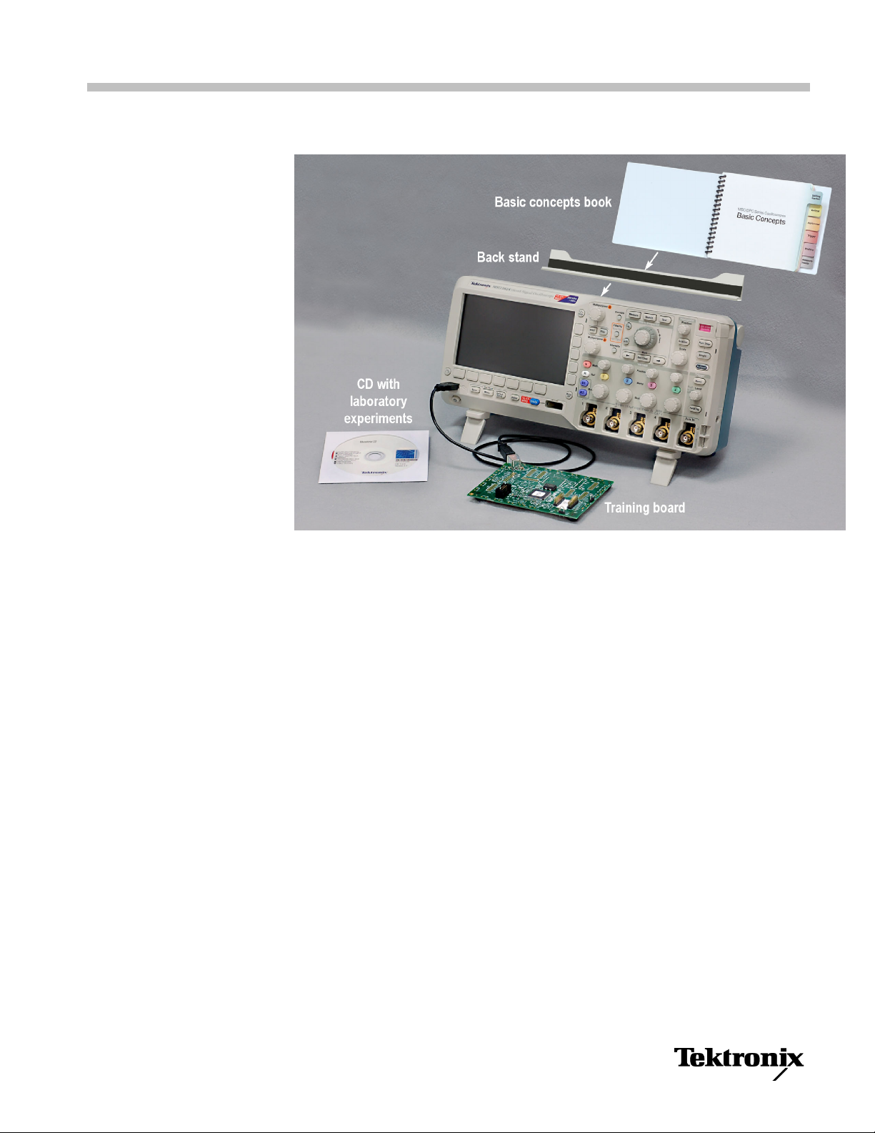
Educator’s Resource Kit
The Educ
engineering students the fundamentals of test and measurement. Included on the
CD are six problem-based laboratory experiments, with matching instructor’s
guides and reference fact sheets , and a training board for use with the experiments.
The laboratory experiments are designed to be scalable from two to four hours
in length to match your lab needs. All instructional materials – lab experiments,
inst
and an editable format (either as a Word document or a PowerPoint file). The
copyright on the instructional materials grants you permission to reprint, modify
and distribute in whole or in part the documents for the purpose of training
students on Tektronix test instrumentation.
An Oscilloscope Basic Concepts book is also included, which covers the basic
features and functions of an oscilloscope. Hardware to attach the Oscilloscope
Basic Concepts to the oscilloscope is provided.
ator’s Resource Kit offers a comprehensive suite of tools for teaching
ructor’s guides and reference fact sheets – are provided in both .pdf format
www.tektronix.com
Copyright © Tektronix
*P071269200*
071-2692-00
Page 2

Educator’s Resource Kit
Resource Kit Contents Description
Six Laboratory Experiments (on the CD):
Introduction to Oscilloscopes
Introduction to Oscilloscope Probes
Advanced Oscilloscope Features
Introduction to Arbitrary/Function Generators
Digital Debug with Oscilloscopes
Parallel and Serial Bus Analysis
Six Instructor’s Guides (on the CD) One for each experiment
Six Refer
Training Board
ence Fact Sheets (on the CD)
Problem-base
Hands-on using real-world signals
Designed to match your lab time; scale from 2 to 4 hours
Answers to the exercises
Helpful hi
Designed
Covers basic test and measurement theory
Reference tools for use during the lab or future classes
Provides signals for:
Noisy si
Digital signal with common anomalies
Parallel bus
RS-232
d learning
nts to performing the experiments
for students
ne wave
serial bus
2
Page 3
Educator’s Resource Kit
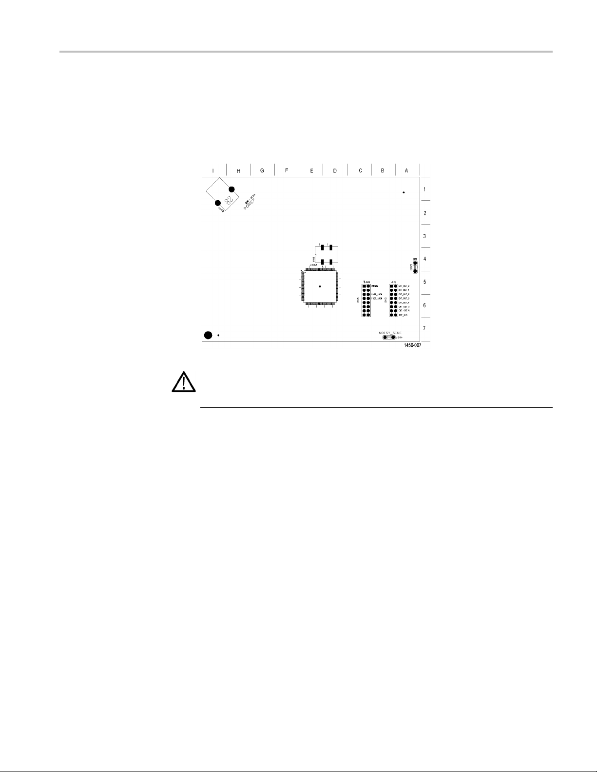
Locating Sign
als on the Training Board
The diagram includes a grid to help you locate signals on the training board
connectors and headers. To find the desired signal on the diagram, look up the
grid locatio
on the diagram and on the board.
ns in the signal description, and then use the grid to find that location
Noisy Sine
RS232 U ART, Transmit
CAUTION. To avoid damage to the training board, handle it in a static conscious
manner. Som
accidental ESD (electro-static discharge).
Board label. NOISY_SINE
Connector grid location. B7
Description. The Noisy Sine signal is a 19.07 Hz sine wave with 64 analog steps
per cycle, resembling those made by a digital-to-analog converter (DAC). It also
has 18 glitches per cycle, resembling those from a switch-mode power supply.
Board label. RS232
Connector grid location. B5 to C5
Description. The UART signal is the logic level input to the RS-232 UART from
the μC. The transmit signal (TX) is the RS-232 voltage level serial bus signal.
The decoded data packets display the ASCII string: “Tektronix”, followed by six
spaces and one error.
e components on the board are susceptible to damage from
There are no matching receive or data flow control signals.
The baud rate is 9600. The data format is 1 start bit, and 8 data bits with no parity.
3
Page 4

Educator’s Resource Kit
Counter Clock
Counter Output Bits
Frequent Anomaly
Board label. CN
Connector grid location. B6
Description. This is the 1.25 MHz clock signal for the 7-bit Counter Output
described next.
Board label. CNT_OUT0: CNT_OUT6
Connector grid location. B5, B6
Description. These are the 7-bits of the binary counter. The least significant bit
(LSB) is CNT OUT0 at 625 KHz, that is half of the counter input clock. The
Counter Output Bits and the Counter Clock signals are on eight adjacent sets of
header pins for easy connection to a digital probe.
Board label. FREQ_ANOM
Connector grid location. B6 to C6
Description. There are three frequently occurring anomalies in this pulse train.
T_CLK
Rare Anomaly
A half height runt signal occurs every 51.2 μs. You can use a Run
isolate the signal.
A 25 ns (narrow) and a 50 ns (narrow) pulse appears every 51.2 μs. You can use a
Pulse Width trigger to isolate each signal.
The pulse train is a repeating group of three pulses. The thre e pulses are 100 ns,
200 ns, and 100 ns wide, with a 100 ns low between. The group repeats at a
1.6 μs rate.
The anomaly is a group of four pulses. The four pulses are 50 ns (narrow), 25 ns
(narrow), 75 ns (runt), and 100 ns wide (full pulse), with a low time between them
of 25 ns, 100 ns, and 225 ns.
Board label. RARE_ANOM
Connector grid location. B6 to C6
Description. There are three less-frequently occurring anomalies in this pulse
train.
A half-height runt signal occurs every 838.8 ms. You can use a Runt trigger to
isolate the signal.
ttriggerto
A 25 ns (narrow) and a 50 ns (narrow) pulse appears every 838.8 ms. You can use
a Pulse Width trigger to isolate each signal.
4
Page 5

Educator’s Resource Kit
The pulse train
200 ns, and 100 ns wide, with a 100 ns low between each pulse. The group
repeats at a 1.6 μs rate.
The anomaly is a group of four pulses. The four pulses are 50 ns (narrow), 25 ns
(narrow), 75 ns (runt), and 100 ns wide (full pulse), with a low time between them
of 25 ns, 100 ns, and 225 ns.
is a repeating group of three pulses. The three pulses are 100 ns,
5
Page 6

Compliance Information
Compliance In
EMC Compliance
EC Declaration of
Conformity – EMC
formation
This section
environmental standards with which the training board complies.
Meets intent of Directive 2004/108/EC for Electromagnetic Compatibility.
Compliance was demonstrated to the following specifications as listed in the
Official Journal of the European Communities:
EN 61326-1 2006. EMC requirements for electrical equipment for measurement,
control, and laboratory use.
CISPR 11:2003. Radiated and conducted emissions, Group 1, Class A
IEC 61000-4-2:2001. Electrostatic discharge immunity
IEC 61000-4-3:2002. RF electromagnetic field immunity
IEC 61000-4-4:2004. Electrical fast transient / burst immunity
IEC 61000-4-5:2001. Power line surge immunity
IEC 61000-4-6:2003. Conducted RF immunity
IEC 61000-4-11:2004. Voltage dips and interruptions immunity
lists the EMC (electromagnetic compliance), safety, and
1234
5
EMC Compliance
EN 61000-3-2:2006. AC power line harmonic emissions
EN 61000-3-3:1995. Voltage changes, fluctuations, and flicker
European Contact.
Tektronix UK, Ltd.
Western Peninsula
Western Road
Bracknell, RG12 1RF
United Kingdom
Meets the intent of Directive 2004/108/EC for Electromagnetic Compatibility
when it is used with the product(s) stated in the specifications table. Refer to the
EMC specification published for the stated products. May not meet the i ntent of
the directive if used with other products.
European Contact.
Tektronix UK, Ltd.
Western Peninsula
Western Road
Bracknell, RG12 1RF
United Kingdom
6
Page 7

Compliance Information
1
This product is
interference.
2
Emissions whi
test object.
3
To e n sure com p
4
This product is intrinsically static sensitive and must be handled in a Static Conscious manner. IEC 61000-4-2 is
considered no
5
Performance Criterion C applied at the 70%/25 cycle Voltage-Dip and the 0%/250 cycle Voltage-Interruption test
levels (IEC 61
Australia / New Zealand
Declaration of
Conformity – EMC
Complies with the EMC provision of the Radiocommunications Act per the
following standard, in accordance with ACMA:
CISPR 11:2003. Radiated and Conducted Emissions, Group 1, Class A, in
accordance with EN 61326-1:2006.
Environmental Considerations
This section provides information about the environmental impact of the product.
intended for use in nonresidential areas only. Use in residential areas may cause electromagnetic
ch exceed the levels required by this standard may occur when this equipment is connected to a
liance with the EMC standards listed here, high quality shielded interface cables should be used.
t applicable.
000-4-11).
Product
triction of Hazardous
Res
End-of-Life
Substances
Handling
Observe the following guidelines when recycling an instrument or component:
Equipment Recycling. Production of this equipment required the extraction and
use of n
atural resources. The equipment may contain substances that could be
harmful to the environment or human health if improperly handled at the product’s
end of life. In order to avoid release of such substances into the environment and
to reduce the use of natural resources, we encourage you to recycle this product
in an appropr iate system that will ensure that most of the materials are reused or
recycled appropriately.
This symbol indicates that this product complies with the applicable European
Union requirements according to Directives 2002/96/EC and 2006/66/EC
on waste electrical and electronic equipment (WEEE) and batteries. For
information about recycling options, check the Support/Service section of the
Tektronix Web site (www.tektronix.com).
This product has been classified as Monitoring and Control equipment, and is
outside the scope of the 2002/95/EC RoHS Directive.
7
 Loading...