

Page 1

xx
ECO8000 Series
ZZZ
Automatic Changeover Unit
User Manual
*P071322100*
071-3221-00
Page 2

Page 3

xx
ECO8000 Series
ZZZ
Automatic Changeover Unit
User Manual
Register now!
Click the following link to protect your product.
► www.tektronix.com/register
www.tektronix.com
071-3221-00
Page 4

Copyright © Tektronix. All rights reserved. Licensed software products are owned by Tektronix or its subsidiaries
or suppliers, and are protected by national copyright laws and international treaty provisions.
Tektronix products are covered by U.S. and foreign patents, issued and pending. Information in this publication
supersedes that in all previously published material. Specifications and price change privileges reserved.
TEKTRONIX and TEK are registered trademarks of Tektronix, Inc.
Contacting Tektronix
Tektronix, Inc.
14150 SW Karl Braun Drive
P.O. B o x 5 0 0
Beaverto
USA
For product information, sales, service, and technical support:
n, OR 97077
In North America, call 1-800-833-9200.
Worl dwid e, v isit www.tektronix.com to find contacts in your area.
Page 5

Warranty
Tektronix warrants that this product will be free from defects in materials and workmanship for a period of one (1)
year from the date of shipment. If any such product proves defective during this warranty period, Tektronix, at its
option, either will repair the defective product without charge for parts and labor, or will provide a replacement
in exchange for the defective product. Parts, modules and replacement products used by Tektronix for warranty
work may be n
the property of Tektronix.
ew or reconditioned to like new performance. All replaced parts, modules and products become
In order to o
the warranty period and make suitable arrangements for the performance of service. Customer shall be responsible
for packaging and shipping the defective product to the service center designated by Tektronix, with shipping
charges prepaid. Tektronix shall pay for the return of the product to Customer if the shipment is to a location within
the country in which the Tektronix service center is located. Customer shall be responsible for paying all shipping
charges, duties, taxes, and any other charges for products returned to any other locations.
This warranty shall not apply to any defect, failure or damage caused by improper use or improper or inadequate
maintenance and care. Tektronix shall not be obligated to furnish service under this warranty a) to repair damage
result
b) to repair damage resulting from improper use or connection to incompatible equipment; c) to repair any damage
or malfunction caused by the use of non-Tektronix supplies; or d) to service a product that has b een modified or
integrated with other products when the effect of such modification or integration increases the time or difficulty
of servicing the product.
THIS WARRANTY IS GIVEN BY TEKTRONIX WITH RESPECT TO THE PRODUCT IN LIEU OF ANY
OTHER WARRANTIES, EXPRESS OR IMPLIED. TEKTRONIX AND ITS VENDORS DISCLAIM ANY
IMPLIED WARRANTIES OF MERCHANTABILITY OR FITNESS FOR A PARTICULAR PURPOSE.
TRONIX' RESPONSIBILITY TO REPAIR OR REPLACE DEFECTIVE PRODUCTS IS THE SOLE
TEK
AND EXCLUSIVE REMEDY PR OVIDED TO THE CUSTOMER FOR BREACH OF THIS WARRANTY.
TEKTRONIX AND ITS VENDORS WILL NOT BE LIABLE FOR ANY INDIRECT, SPECIAL, INCIDENTAL,
OR CONSEQUENTIAL DAMAGES IRRESPECTIVE OF WHETHER TEKTRONIX OR THE VENDOR HAS
ADVANCE NOTICE OF THE POSSIBILITY OF SUCH DAMAGES.
[W2 – 15AUG04]
btain service under this warranty, Customer must notify Tektronix of the defect before the expiration of
ing from attempts by personnel other than Tektronix representatives to install, repair or service the product;
Page 6

Page 7

Table of Contents
Important safety information....... .................................. ................................ ............ iv
General safety summary ..................................................................................... iv
Service safety summary ................................ ................................ ...................... vi
Terms in this manual . ................................ .................................. ..................... vii
Symbols and terms on the product......................................................................... vii
Compliance information ......................................................................................... viii
EMC compliance ......... ................................ ................................ ................... viii
Safety compliance ............................................................................................ ix
Environmental considerations............................................................................... xi
Preface ............................................................................................................. xiii
Product description ................... .................................. ................................ ..... xiii
Product documentation....... ................................ ................................ ................ xv
Conventions Used in This Manual.................................. .................................. ...... xv
Getting Started ..... . ..... . ..... ..... . ..... . ..... . .... . . .... . ..... . ..... . ..... ..... . ..... . ..... . .... . . .... . ..... . .... 1
Initial product inspection. ..... . ..... . ..... . .... . ..... . ..... . ..... . ... . . ..... . ..... . .... . . .... . ..... . ..... . .... 1
Accessories..................................................................................................... 2
Product installation ....................... ................................ .................................. ... 3
Network installation........................................................................................... 7
System considerations................ ................................ ................................ ........ 11
Signal connections .............................. .................................. ............................ 12
Operating Basics................................................................................................... 17
Operational overview... ................................ ................................ ...................... 17
Controls, connectors, and LED indicators ................................................................. 19
Initial product setup . ..... ..... . ..... . .... . . .... . ..... . ... . . ..... . ..... . .... . ..... . ..... . .... . ..... . ... . . . .... 28
How to operate an instrument with two power supplies (Option DPW only).......................... 36
How to upgrade the inst
How to use the Event Log and event history .......... .................................. .................. 48
Menus................... .................................. ................................ .......................... 53
Menu navigation .............................................................................................. 53
Main menu..................................................................................................... 54
STATUS menu ...... .................................. ................................ ........................ 56
CHANNEL menu................. ................................ ................................ ............ 62
SYSTEM CONFIG menu. . ... . . . .... . ..... . ..... ..... . ..... . ..... . .... . ..... . ..... . ... . . ..... . ..... . .... . ... 65
Remote control............................... ................................ .................................. .... 95
How to use the Web Interface ............................................................................... 95
How to use SNMP.............. ................................ ................................ .............. 98
Index
rument firmware .......... ................................ ........................ 40
ECO8000 Series Automatic Changeover Unit User Manual i
Page 8

Table of Contents
List of Figure
Figure 1: Installing or removing the instrument into or from the rack . .... . ..... . ..... . ..... . .... . . .... . .... 5
Figure 2: Location of rear panel power connectors (ECO8000 shown)...................................... 7
Figure 3: ECO8000 and SPG8000 system installation example ............................................. 13
Figure 4: ECO8020 and SPG8000 system installation example ............................................. 15
Figure 5: ECO8000 Series subsystems (ECO8020 with Option DPW shown)............................. 17
Figure 6: ECO8000 controls
Figure 7: ECO8020 controls and connectors............... ................................ .................... 19
Figure 8: Removing a Power Supply module .................. .................................. .............. 39
Figure 9: Installing the backup or replacement Power Supply module. . ..... . ..... . ..... . ..... . ..... . ...... 40
Figure 10: Sample of transfer.exe window after the upgrade is complete ........ .......................... 45
Figure 11: Main menu ............................................................................................ 54
Figure 12: STATUS menu.............. .................................. ................................ ........ 56
Figure 13: EVENT LOG (BY TYPE) submenu – part 1...................................................... 58
Figure 14: EVENT LOG (BY TYPE) submenu – part 2...................................................... 59
Figure 15: EVENT LOG (BY TYPE) submenu – part 3...................................................... 60
Figure 16: EVENT LOG (BY TIME) submenu ..................... ................................ .......... 61
Figure 17: CHANNEL submenu ................ .................................. .............................. 62
Figure 18: Custom level threshold display ....................... ................................ .............. 63
Figure 19: SYSTEM CONFIG menu – part 1.. . ..... . ..... ..... . ..... . ..... . ..... . .... . . .... . ..... . ..... . ..... 65
Figure 20: SYSTEM CONFIG menu – part 2.. . ..... . ..... ..... . ..... . ..... . ..... . .... . . .... . ..... . ..... . ..... 66
Figure 21: SYSTEM CONFIG menu – part 3.. . ..... . ..... ..... . ..... . ..... . ..... . .... . . .... . ..... . ..... . ..... 67
Figure 22: NETWORK CONFIG submenu .................................................................... 72
Figure 23: SNMP CONFIG submenu............. ................................ .............................. 74
Figure 24: EMAIL REPORTING submenu ...................... .................................. ............ 76
Figure 25: INTERNAL CLOCK submenu ................. .................................. .................. 79
Figure 26: SET LOCAL TIME submenu..................... .................................. ................ 80
Figure 27: DST SCHEDULE submenu..... .................................. ................................ .. 81
Figure 28: <type> EVENTS submenu – part 1 ................................................................ 84
Figure 29: <type> EVENTS submenu – part 2 ................................................................ 85
Figure 30: <type> EVENTS submenu – part 3 ................................................................ 86
Figure 31: OPTIONS ENABLED submenu.................................................................... 87
Figure 32: DIAGNOSTICS submenu – part 1 ... ................................ .............................. 89
Figure 33: DIAGNOSTICS submenu – part 2 ... ................................ .............................. 90
Figure 34: Example ECO8020 Web Interface window ... ................................ .................... 97
s
and connectors............... .................................. .................. 19
ii ECO8000 Series Automatic Changeover Unit User Manual
Page 9

List of Tables
Table 1: Standard and optional accessories...................................................................... 2
Table 2 : ECO
Table 3: AC line power requirements ............................................................................ 6
Table 4: Example plan for connecting signals to an ECO8000............................... ................ 12
Table 5: ECO8000 and SPG8000 system installation example connections...................... .......... 13
Table 6: ECO8020 and SPG8000 system installation example connections...................... .......... 15
Table 7: GPIO connector signal pinouts ........................................................................ 22
Table 8 : L
Table 9: LTC OUT connector signal pinouts ................................................................... 24
Table 10: Power on LED states for a Power Supply module ................................................. 25
Table 11: Power off LED states for a Power Supply module................................................. 26
Table 12: Self test error codes........................ ................................ ............................ 27
Table 13: SPG trigger cable connections and GPI configuration..................................... ........ 32
14: Signal pinouts for the SPG8000 GPI/LTC connector and the TG8000 GPS7 module LTC/GPI
Table
connector ...................................................................................................... 32
Table 15: Signal pinouts for the SPG8000 GPI connector.................................................... 33
Table 16: Signal pinouts for the TG8000 GPI port . .................................. ........................ 33
Table 17: Fault and event descriptions............ .................................. ............................ 49
Table 18: Relationship between module and channel numbers ........ ................................ ...... 50
le 19: Board voltage error codes..................................... ................................ ........ 51
Tab
Table 20: Event reporting methods and menu access points.................................................. 83
Table 21: Relationship between module and channel numbers ........ ................................ ...... 92
Table 22: Elements of the Web user interface .................................. ................................ 98
Table 23: SNMP parameters ..................................................................................... 99
8000 Series environmental requirements......... ................................ ............... 3
TC/SPG connector signal pinouts.................................................................... 23
Table of Contents
ECO8000 Series Automatic Changeover Unit User Manual iii
Page 10

Important safety information
Important saf
ety information
This manual c
for safe operation and to keep the product in a safe condition.
To saf ely p e
the end of this section. (See page vi, Servicesafetysummary.)
General safety summary
Use the product only as specified. Review the following safety precautions to
avoid injury and prevent damage to this product or any products connected to it.
Carefully read all instructions. Retain these instructions for future reference.
Comply with local and national safety codes.
For correct and safe operation of the product, it is essential that you follow
generally accepted safety procedures in addition to the safety precautions specified
in this manual.
The product is designed to be used by trained personnel only.
Only qualified personnel who are aware of the hazards involved should remove
the cover for repair, maintenance, or adjustment.
ontains information and warnings that must be followed by the user
rform service on this product, additional information is provided at
Before use, always check the product with a known source to be sure it is
operating correctly.
This product is not intended for detection of hazardous voltages.
personal protective equipment to prevent shock and arc b last injury where
Use
hazardous live conductors are exposed.
ile using this product, you may need to access other parts of a larger system.
Wh
Read the safety sections of the other component manuals for warnings and
cautions related to operating the system.
When incorporating this equipment into a system, the safety of that system is the
responsibility of the assembler of the system.
iv ECO8000 Series Automatic Changeover Unit User Manual
Page 11

Important safety information
To avoid fire or
personal
injury
Use proper powe
certified for the country of use.
Do not use the p
Ground the product. This product is grounded through the grounding conductor
of the power cord. To avoid electric shock, the grounding conductor must be
connected to earth ground. Before making connections to the input or output
terminals of the product, make sure that the product is properly grounded.
Do not disable the power cord grounding connection.
Power disconnect. The power cord disconnects the product from the power
source. S
it is difficult to operate the power cord; it must remain accessible to the user at
all times to allow for quick disconnection if needed.
Observe all terminal ratings. To avoid fire or shock hazard, observe all ratings
and markings on the product.
Do not operate without covers. Do not operate this product with covers or panels
removed, or with the case open. Hazardous voltage exposure is possible.
ee instructions for the location. Do not position the equipment so that
r cord. Use only the power cord specified for this product and
rovided power cord for other products.
Do not operate with suspected failures. If you suspect that there is damage to this
product, have it inspected by qualified service personnel.
Disable the product if it is damaged. Do not use the product if it is damaged
or operates incorrectly. If in doubt about safety of the product, turn it off and
connect the power cord. Clearly mark the product to prevent its further
dis
operation.
amine the exterior of the product before you use it. Look for cracks or missing
Ex
pieces.
Do not operate in wet/damp conditions. Be aware that condensation may occur if
a unit is moved from a cold to a warm environment.
Do not operate in an explosive atmosphere.
Keep product surfaces clean and dry. Remove the input signals before you clean
the product.
ECO8000 Series Automatic Changeover Unit User Manual v
Page 12

Important safety information
Provide proper
details on installing the product so it has proper v entilation.
Slots and open
otherwise obstructed. Do not push objects into any of the openings.
Provide a safe working environment. Always place the product in a location
convenient for viewing the display and indicators.
Be sure your work area meets applicable ergonomic standards. Consult with an
ergonomics professional to avoid stress injuries.
Use only the Tektronix rackmount hardware specified for this product.
Servicesafetysummary
The Service safety summary section contains additional information required to
safely perform service on the product. Only qualified personnel should perform
service procedures. Read this Service safety summary and the General safety
summar
To avoid electric shock. Do not touch exposed connections.
ventilation. Refer to the installation instructions in the manual for
ings are provided for ventilation and should never be covered or
y before performing any service procedures.
Do not service alone. Do not perform internal service or adjustments of this
product unless another person capable of rendering first aid and resuscitation is
ent.
pres
Disconnect power. To avoid electric shock, switch off the product power and
disconnect the power cord from the mains power before removing any covers or
panels, or opening the case for servicing.
e care when servicing with power on. Dangerous voltages or currents may exist
Us
in this product. Disconnect power, remove battery (if applicable), and disconnect
test leads before removing protective panels, soldering, or replacing components.
Verify safety after repair. Always recheck ground continuity and mains dielectric
strength after performing a repair.
vi ECO8000 Series Automatic Changeover Unit User Manual
Page 13

Terms in this manual
These terms may appear in this manual:
WAR NI NG . Warning statements identify conditions or practices that could result
in injury or loss of life.
CAUTION. Caution statements identify conditions or practices that could result in
damage to this product or other property.
Symbols and terms on the product
Important safety information
These ter
The following symbol(s) may appear on the product:
ms may appear on the product:
DANGER indicates an injury hazard immediately accessible as you read
the mark
WARNING indicates an injury hazard not immediately accessible as you
read th
CAUTION indicates a hazard to property including the product.
ing.
emarking.
When this symbol is marked on the product, be sure to consult the manual
to find out the nature of the potential hazards and any actions which have to
be taken to avoid them. (This symbol may also be used to refer the user to
ratings in the manual.)
ECO8000 Series Automatic Changeover Unit User Manual vii
Page 14

Compliance information
Compliance in
EMC compliance
EC Declaration of
Conformity – EMC
formation
This section
environmental standards with which the instrument complies.
Meets intent of Directive 2004/108/EC for Electromagnetic Compatibility.
Compliance was demonstrated to the followin
Official Journal of the European Communities:
EN 55103:1996. Product family standard for audio, video, audio-visual and
entertainment lighting control apparatus for professional use.
Environment E2 – commercial and light industrial
Part 1 Emission
Part 2 Immunity
lists the EMC (electromagnetic compliance), safety, and
g specifications as listed in the
12
EN 55022:1987. Class B radiated and conducted emissions
EN 55103-1:1996 Annex A. Radiated magnetic field emissions
IEC 61000-4-2:2001. Electrostatic discharge immunity
IEC 61000-4-3:2006. RF electromagnetic field immunity
IEC 61000-4-4:2004. Electrical fast transient / burst immunity
IEC 61000-4-5:2005. Power line surge immunity
IEC 61000-4-6:2003. Conducted RF Immunity
IEC 61000-4-11:2004. Voltage dips and interruptions immunity
EN 55103-2:1996 Annex A Radiated magnetic field immunity
EN 61000-3-2:2006. AC power line harmonic emissions
EN 61000-3-3:1995. Voltage changes, fluctuations, and flicker
European contact.
Tektronix UK, Ltd.
Western Peninsula
Western Road
Bracknell, RG12 1RF
United Kingdom
1
For compliance with the EMC standards listed here, high quality shielded interface cables should be used.
2
Average half-cycle r.m.s. inrush current at initial switch-on, and after a 5 second power interruption, is 2 A.
viii ECO8000 Series Automatic Changeover Unit User Manual
Page 15

Compliance information
Australia / New Zealand
Declaration of
Conformity – EMC
Safety compliance
EU declaration of
conformity – low voltage
Complies with t
following standard, in accordance with ACMA:
EN 55022:1987
with EN 55103-1:1996.
Australia / New Zealand contact.
Baker & McKenzie
Level 27, AMP Centre
50 Bridge Street
Sydney NSW 2000, Australia
This section lists the safety standards with which the product complies and other
safety c
Compliance was demonstrated to the following specification as listed in the
Official Journal of the European Union:
Low Voltage Directive 2006/95/EC.
ompliance information.
he EMC provision of the Radiocommunications Act per the
. Radiated and conducted emissions, Class B , in accordance
nationally recognized
U.S.
testing laboratory lis ting
Canadian certification
Additional compliances
Equipment type
Safety class
EN 61010-1. Safety Requirements for Electrical Equipment for Measurement,
Control, and Laboratory Use – Part 1: General Requirements.
UL 61010-1. Safety Requirements for Electrical Equipment for Measurement,
Control, and Laboratory Use – Part 1: General Requirements.
CAN/CSA-C22.2 No. 61010-1. Safety Requirements for Electrical
Equipment for Measurement, Control, and Laboratory Use – Part 1: General
Requirements.
IEC 61010-1. Safety Requirements for Electrical Equipment for
Measurement, Control, and Laboratory Use – Part 1: General Requirements.
Test and measuring equipment.
Class1–groundedproduct.
ECO8000 Series Automatic Changeover Unit User Manual ix
Page 16

Compliance information
Pollution degree
descriptions
Pollution degree rating
A measure of the
and within a product. Typically the internal environment inside a product is
considered to be the same as the external. Products should be used only in the
environment for which they are rated.
Pollution degree 1. No pollution or only dry, nonconductive pollution occurs.
Products in this category are generally encapsulated, hermetically sealed, or
located in clean rooms.
Pollution degree 2. Normally only dry, nonconductive pollution occurs.
Occasionally a temporary conductivity that is caused by condensation must
be expected. This location is a typical office/home environment. Temporary
condensa
Pollution degree 3. Conductive pollution, or dry, nonconductive pollution
that bec
where neither temperature nor humidity is controlled. The area is protected
from direct sunshine, rain, or direct wind.
Pollution degree 4. Pollution that generates persistent conductivity through
conductive dust, rain, or snow. Typical outdoor locations.
tion degree 2 (as defined in IEC 61010-1). Rated for indoor, dry location
Pollu
use only.
contaminants that could occur in the environment around
tion occurs only when the product is out of service.
omes conductive due to condensation. These are sheltered locations
IP rating
Measurement and
overvoltage category
descriptions
Mains overvoltage
category rating
IP20 (as defined in IEC 60529).
surement terminals on this product may be rated for measuring mains voltages
Mea
from one or more of the following categories (see specific ratings marked on
the product and in the manual).
Category II. Circuits directly connected to the building wiring at utilization
points (socket outlets and similar points).
Category III. In the building wiring and distribution system.
Category IV. At the source of the electrical supply to the building.
NOTE. Only mains power supply circuits have an overvoltage c ategory rating.
Only measurement circuits have a measurement category rating. Other circuits
within the product do not have either rating.
Overvoltage category II (as defined in IEC 61010-1).
x ECO8000 Series Automatic Changeover Unit User Manual
Page 17

Environmental considerations
This section provides information about the environmental impact of the product.
Compliance information
Product end-of-life
handling
Restriction of hazardous
tances
subs
Observe the f
Equipment recycling. Production of this equipment required the extraction and
use of natural resources. The equipment may contain substances that could be
harmful to the environment or human health if improperly handled at the product’s
end of life. To avoid release of such substances into the environment and to
reduce the
an appropriate system that will ensure that most of the materials are reused or
recycled appropriately.
Perchlorate materials. This product contains one or more type CR lithium
batteries. According to the state of California, CR lithium batteries are
ified as perchlorate materials and require special h andling. See
class
www.dtsc.ca.gov/hazardouswaste/perchlorate for additional information.
This product is classified as an industrial monitoring and control instrument,
s not required to comply with the substance restrictions of the recast RoHS
and i
Directive 2011/65/EU until July 22, 2017.
ollowing guidelines when recycling an instrument or component:
use of n atural resources, we encourage you to recycle this product in
This symbol indicates that this product complies with the applicable European
Union re
on waste electrical and electronic equipment (WEEE) and batteries. For
information about recycling options, check the Support/Service section of the
Tekt r on
quirements according to Directives 2002/96/EC and 2006/66/EC
ixWebsite(www.tektronix.com).
ECO8000 Series Automatic Changeover Unit User Manual xi
Page 18

Compliance information
xii ECO8000 Series Automatic Changeover Unit User Manual
Page 19

Preface
Preface
Product description
This manual p
Automatic Changeover Unit. Also included is information about basic instrument
operation.
The ECO8000 Series Automatic Changeover Unit is a highly versatile automatic
sync and signal changeover unit with configurations and capabilities r equired
to address modern master sync application and other advanced sync timing
application. The ECO8000 Series offers exceptional reliability, stability, and is
designed
and/or 3G-SDI signal environments.
Each ECO
complete sync generator system, which offers extra redundancy for the critical
timing and synchronization system in the facilities.
A pair of Tektronix Master Sync / Master Clock Reference Generators
(SPG8000) for most broadcast facility timing applications.
A pair of Tektronix Test Signal Generators (TG8000) for more advanced post
production facility timing applications.
rovides safety and installation information for the ECO8000 Series
with optional high-bandwidth input changeover capabilities for HD/SD
8000 unit can be used with the following signal generators to form the
ECO8000 Series models
ECO8000 Series consist of the following models:
The
ECO8000: This model provides up to nine user-configurable BNC channels
d four LTC channels. The base configuration has three 50 MHz Electronic
an
Fast Switch (REF/ELSW) channels with options for six more 50 MHz
Electronic Fast Switch or 3 GHz Relay Switch (HREF/Relay) channels in
groups of three channels each, plus four optional LTC channels. Each channel
consisting of primary and backup inputs, and an output.
ECO8020: This model provides up to 20 user-configurable high-density
BNC channels and four LTC channels. The base configuration has five 50
MHz Electronic Fast Switch (REF/ELSW) channels with options for 15
more 50 MHz Electronic Fast Switch or 3 GHz Relay Switch (HREF/Relay)
channels in groups of five channels each, plus four optional LTC channels.
Each channel consisting of primary and backup inputs, and an output.
ECO8000 Series Automatic Changeover Unit User Manual xiii
Page 20

Preface
Key features and benefits
Innovative arc
advanced monitoring capability
Switches anal
LTC, as well as 3G-SDI, HD-SDI, and SD-SDI signals – all the timing and
synchronization signals required in modern broadcast, production, and post
production facilities
Scalable product architecture to fit various application needs
Electronic Fast Switch function for near glitch-less sync source switching,
minimizing disruption in operations if a switch is necessary to service the
primary sync source
Relay backups provide continued signal connection in the event that the
ECO loses power
Automatic and Manual changeover modes with indicator
Front panel LED indicators for the status o f each Primary and Backup channel
Front p
supply
Dual h
reference s ignals
anel LED indicators for the AC and DC status of each installed power
ot-swappable power supplies ensure continuous availability of
hitecture provides highly reliable basic ECO function and
og black burst, HD tri-level sync, AES/DARS, word clock,
Web Interface. An easy to navigate Web-based interface allows quick access to
most of the instrument settings and views. (See page 95, How to use the Web
Interface.) In most cases, it is easier to access and configure the instrument using
Web Interface. Examples of where this is especially true are:
the
Viewing instrument status
Viewing the Event Log
Viewing diagnostic results
Configuring event reporting
Configuring e-mail reporting
Configuring channel settings such as threshold levels, labels, etc.
xiv ECO8000 Series Automatic Changeover Unit User Manual
Page 21
Product documentation
Product documentation
To read about Use these documents
Product safety, installation, and
operation
Product specifications and
performan
Servicin
Clearing or sanitizing the product ECO8000 Series Declassification and Security Instructions
New features or known operational
issues
Softwa
ce verification
g the product
re licenses
ECO8000 Series User Manual
(Tektronix part number 071-3221-xx (English))
(Tektronix p
(Tektronix part number 077-0874-00 (Russian))
ECO8000 Series Video System Integration Technical Reference
(Tektronix part number 077-0877-00)
ECO8000 Series Specifications and Performance Verification Technical Reference
(Tektroni
ECO8000 S
(Tektronix part number 077-0880-00)
(Tektronix part number 077-0879-00)
ECO8000 Series Release Notes
(Tektro
tware licenses used by the ECO8000 Series are available for download from the
The sof
Tektronix Web site. T he licenses are bundled with the product firmware package.
art number 077-0873-00 (Japanese))
x part number 077-0876-00)
eries Service Manual
nix part number 077-0878-00)
Preface
Conve
ntions Used in This Manual
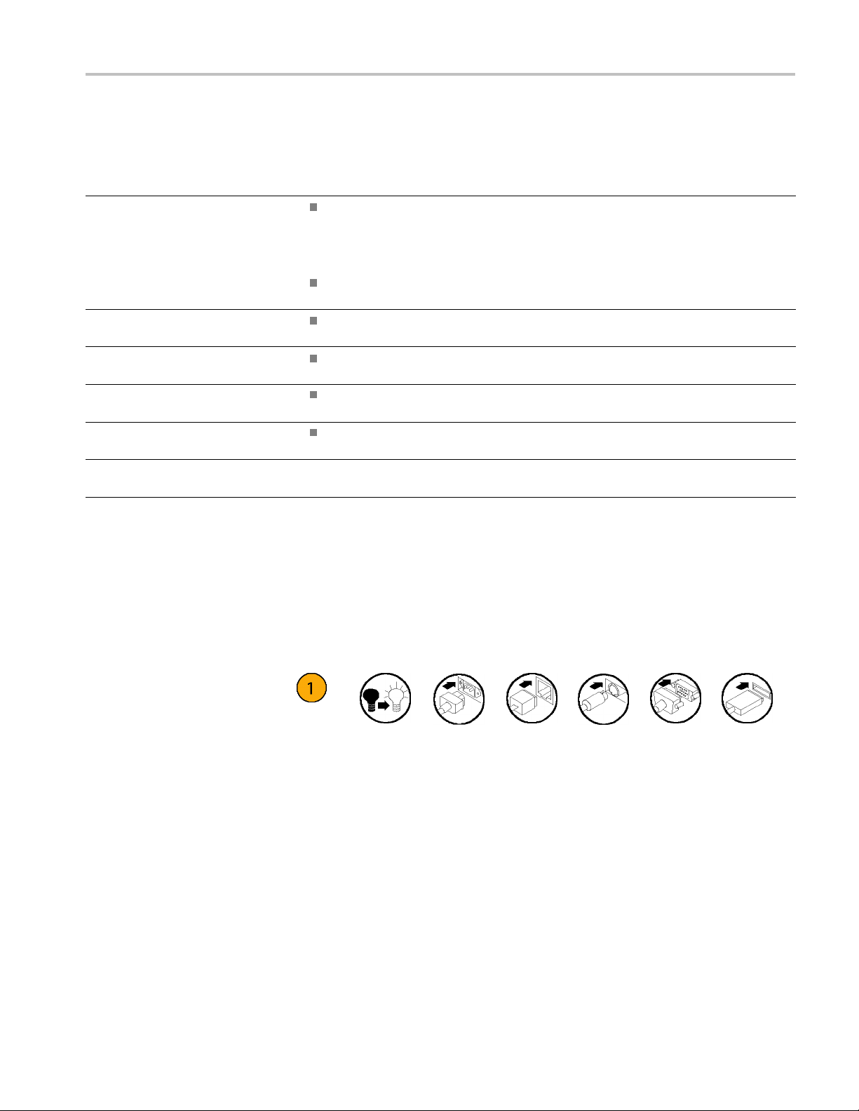
The following icons are used throughout this manual.
Sequence
Step
Fron
panel
power
t
Connect
power
Netw
ork
PS2 SVGA USB
ECO8000 Series Automatic Changeover Unit User Manual xv
Page 22

Preface
xvi ECO8000 Series Automatic Changeover Unit User Manual
Page 23

Getting Started
Initial produ
ct inspection
Perform the following product inspection procedure when you receive your
instrument:
1. Inspect the shipping carton for external damage, which may indicate damage
2. Remove the instrument from the shipping carton, and then check that the
NOTE. Save the shipping carton and packaging materials for instrument
repackaging in case shipment becomes necessary.
3. Verify that the shipping carton contains the basic instrument, all modules
Contact your local Tektronix Field Office or representative if there is a problem
with your instrument or if your shipment is incomplete.
to the instrument.
instrument has not been damaged in transit. Prior to shipment the instrument
is thorou
any scratches or impact marks.
you ordered, the standard accessories and any optional accessories that you
ordered listed in the table. (See Table 1.)
ghly inspected for mechanical defects. The exterior should not have
ECO8000 Series Automatic Changeover Unit User Manual 1
Page 24

Getting Started
Accessories
The following table lists the standard and optional accessories provided with
the ECO8000 Series product.
Table 1: Standard and optional accessories
Tektronix
Accessory Std. Opt.
ECO8000 Ser
Japanese and Russian language versions are available in
PDF format on the Tektronix Web site.
Power cord
(See page 2, International power cord options.)
Rackmount slides and rails kit (Option RACK only)
Adapter cable (6 feet long) from 15-pin D-sub LTC OUT
connect
LTC outputs) and 3 BNC male connectors (for General
Purpose Interface outputs) (Option XLR only)
Coaxial adapter cables from high-density m ale BNC
connec
cables, 75 Ω, 18 inches long) (ECO8020 Option CBL only)
1
To reorder the rack mounting kit, order ECO800UP or ECO802UP Option RACK.
2
To reor
3
To reorder the set of BNC adapter cables, order ECO802UP Option CBL.
ies User Manual (English)
or on the ECO8000 to 4 XLR male connectors (for
tor to standard male BNC connector (a set of 10
der the XLR adapter cable, order ECO800UP or ECO802UP Option XLR.
●
●
●
●
●
part number
071-3221-xx
Varies by
option
1
NA
2
NA
3
NA
International power cord
ns
optio
All of the available power cord options listed below include a lock mechanism
pt as otherwise noted.
exce
Opt. A0 – North America power (standard)
Opt. A1 – Universal EURO power
Opt. A2 – United Kingdom power
Opt. A3 – Australia power
Opt. A5 – Switzerland power
t. A6 – Japan power
Op
Opt. A10 – China power
Opt. A11 – India power (no locking cable)
Opt. A12 – Brazil power (no locking cable)
Opt. A99 – No power cord
2 ECO8000 Series Automatic Changeover Unit User Manual
Page 25

Product installation
Getting Started
Environmental operating
requirements
Check that the location of your installation has the proper operating environment
as listed in the following table. (See Table 2.)
CAUTION. Damage to the instrument can occur if this instrument is powered on at
temperatures outside the specified temperature range.
Table 2: ECO8000 Series environmental requirements
Parameter Description
Temperature
Relative
Humidity
de
Altitu
Operating 0 °C to +50 °C
Nonoperating
Operating 20% to 80% (No condensation); Maximum wet-bulb
Nonoperating
Operating To 3,000 m (9,842 feet)
Nonoperating
–20 °C to +60 °C
temperat
5% to 90%
temperature 40.0 °C
Maximum operating temperature decreases 1 °C for
each 30
To 15,
ure 29.0 °C
(No condensation); Maximum wet-bulb
0 m above 1.5 km.
000 m (49,212 feet)
Leave space for cooling by ensuring standard side clearance for rack mounting or
2 inches (5.1 cm) of side clearance for benchtop use. Also, ensure sufficient rear
clearance (approximately 2 inches) so that cables are not damaged by sharp bends.
For complete specifications for the instrument, refer to the ECO8000 Series
Specifications and Performance Verification Technical Reference. You can locate
this document on the Tektronix Web site (www.tektronix.com\downloads).
ECO8000 Series Automatic Changeover Unit User Manual 3
Page 26

Getting Started
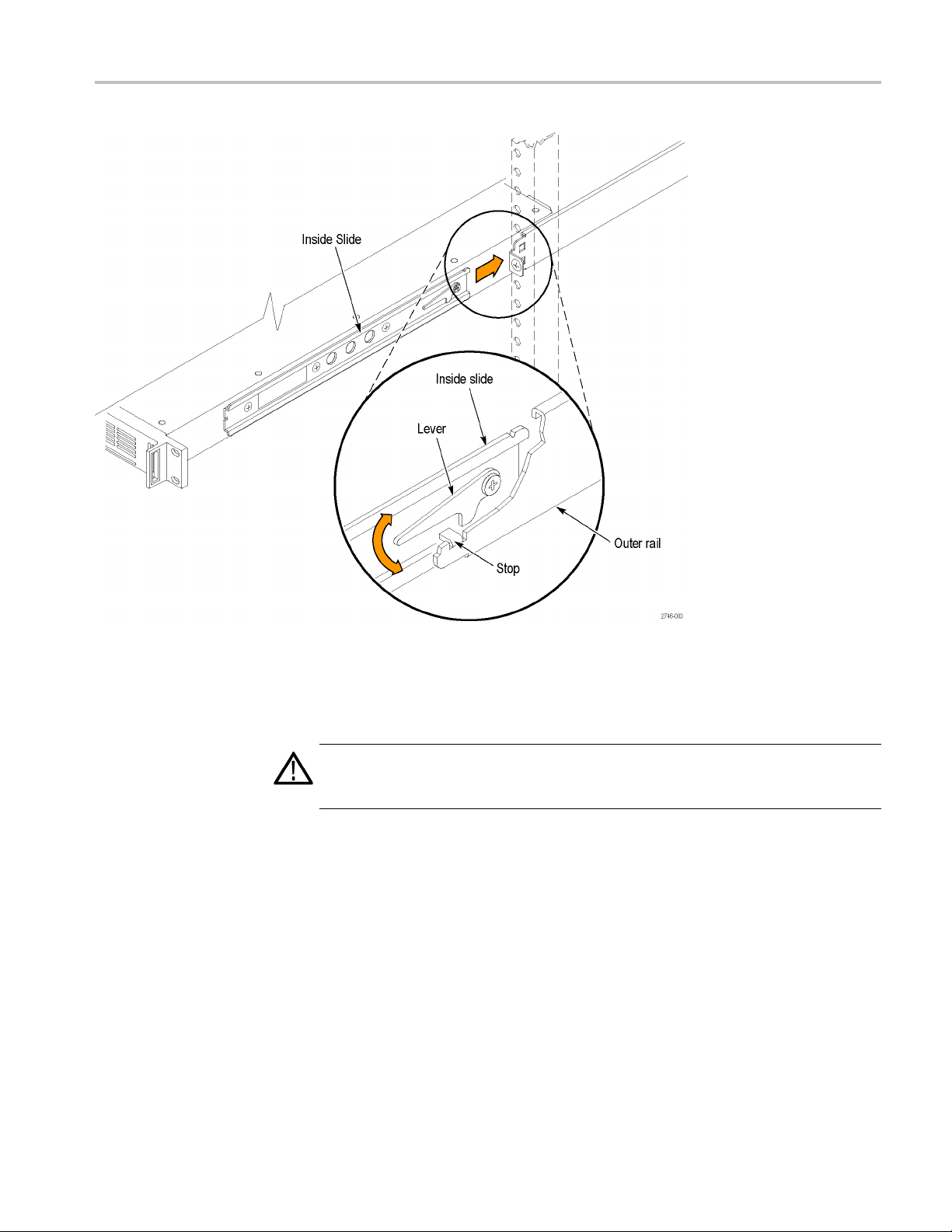
Rackmount installation
(Option RACK only)
This instrumen
if Option RACK was ordered. Refer to the Rackmount Slides and Rails Kit
Instructions, Tektronix part number 071-2746-XX, that was supplied with the
instrument for instructions on how to install the rackmounting hardware.
WARNING. Personal injury or damage to the instrument can occur if the
instrument is not properly secured in the equipment rack.
To install the instrument into an equipment rack. After you have installed the
rackmounting hardware, perform the following steps to install the instrument
into an eq
WARNING. To prevent injury during product installation, use care not to pinch
hands or fingers in the rails and slides.
1. Insert the instrument left and right slides into the ends of the rack rails while
tilting the long handle part of each lever upward. (See Figure 1.)
NOTE. Make sure to insert the instrument slides inside the inner rack rails. You
may also need to tilt the rear of the instrument up or down at a slight angle to fit
the slides into the rails.
tisconfigured at shipment for use in an equipment rack only
uipment rack:
2. Push the instrument into the rack until it stops.
CAUTION. To prevent damage to the instrument and rackmount, do not force the
instrument into the rack if it does not slide smoothly. The rails assembly may need
to be adjusted to resolve the problem.
3. Retighten any loose screws and push the instrument all the way into the rack.
If the tracks do not slide smoothly, readjust the rail assemblies.
4. When adjusting is completed, tighten all rail assembly 10-32 screws using
28 inch-lbs of torque.
5. If the instrument has knob screws on the front corners, tighten them so that
they are secured in the rack.
6. To remove the instrument from the rack, loosen the knob screws.
4 ECO8000 Series Automatic Changeover Unit User Manual
Page 27
Getting Started
Figure 1: Installing o r removing the instrument into or from the rack
To remove the instrument from an equipment rack. Perform the following steps to
remove an instrument that is installed in an equipment rack:
WAR NI NG . To prevent injury when removing the product from the rack, do not
forcefully and abruptly pull the product from the rack. Pull with the minimum
erequiredtomovetheinstrumentwith a consistent, even motion.
forc
1. Loosen the knob screws, if present, that attach the front of the instrument
he rack.
to t
2. Gently pull the instrument toward you until you can reach the levers at the
ar of the instrument.
re
3. Tilt both lever handles upward simultaneously to allow them to clear the
tops. (See Figure 1.)
s
4. Pull the instrument past the stops and out of the rack.
ECO8000 Series Automatic Changeover Unit User Manual 5
Page 28

Getting Started
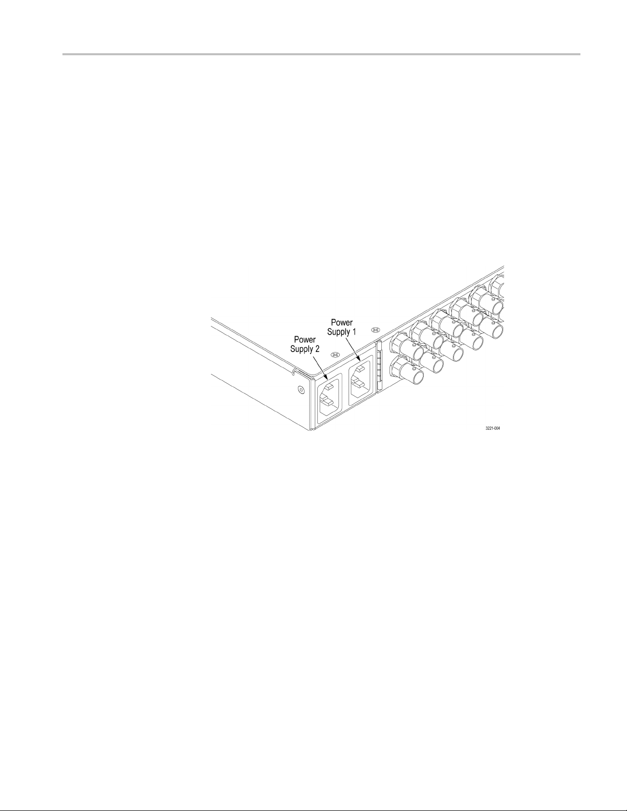
Power connection
This instrumen
t operates from a single-phase power source with the neutral
conductor at or near earth ground. The line conductor is fused for over-current
protection. A protective ground connection through the grounding conductor in
the locking power cord is essential for safe operation.
CAUTION. The instrument does not have a power switch. When you connect
the power plug to one of the AC line connectors, and the Power Supply module
for that slo
t is installed, the instrument powers on. If you have only one power
supply installed, be sure to connect the power plug to the correct rear-panel
power connector.
AC power r
equirements. Check that your location provides the proper electrical
power requirements as listed in the following table. (See Table 3.)
Table 3: AC line power requirements
Parameter Description
ltage Range
Line Vo
100 - 240 VAC
WAR NI NG . To reduce the risk of fire
ck, ensure that the mains supply
and sho
voltage fluctuations do not exceed 10% of
the operating voltage range.
Line frequency 50/60 Hz
Maximum power 50 VA
6 ECO8000 Series Automatic Changeover Unit User Manual
Page 29
Getting Started
Connect the pow
Supply module installed in slot 1. If you ordered Option DPW, your instrument
was shipped with two Power Supply modules installed.
Connect the power cable(s) to the instrument first, and then connect it to the AC
power source. Connecting the power cable causes the instrument to power on.
After connecting the power, make sure that the fan in the instrument is working.
If the fan is not working, turn off the power by disconnecting the power cable
from the AC power source, and then contact your local Tektronix Field Office
or representative.
A power-on self test is run when the instrument firstbootsup. (Seepage27,
Power-on self test.)
er cable(s). Standard instruments are shipped with one Power
Network installation
Figure 2: Location of rear panel power connectors (ECO8000 shown)
Configure the preferred supply (Option DPW only). If your instrument has two
Power Supply modules installed, configure one of the supplies to be the preferred
tive) supply. (See page 37, Configuring the p referred (active) supply (Option
(ac
DPW only).)
The ECO8000 Series has a 10/100 BASE-T Ethernet port on the rear panel that
allowsyoutouseaPCtoremotelycontroltheinstrument.
This section provides instructions for connecting the ECO8000 Series to a single
PC or to a network and for setting the network parameters on the Ethernet port.
ECO8000 Series Automatic Changeover Unit User Manual 7
Page 30

Getting Started
Connecting the instrument
to your PC(s)
To configure the network
parameters
You can use one o
PC(s):
If you are conn
cable to connect between the Ethernet port on the instrument and the Ethernet
port on th e PC.
If you are connecting the instrument to your local Ethernet network, use an
Ethernet cable to connect between the Ethernet port on the instrument and
the Ethernet hub port of your local network. By connecting to an Ethernet
network, you can access the instrument using any PC on the network.
The following two procedures describe how to configure the ECO8000 Series
network parameters. Use the first procedure if your network supports DHCP; use
the second procedure if your network does not support DHCP.
To config
a DHCP server, perform the following steps to configure the instrument to
function as a DHCP client. When the instrument is connected to the network and
DHCP service is enabled, the instrument obtains the necessary network addresses
automatically from the DHCP server.
NOTE. Under some network environments, the instrument may not be able to
get t
manually enter the appropriate network parameter values.
ure parameters for a network with a DHCP server. If your network has
he IP address automatically from a DHCP server. In this case, you need to
f the following two methods to connect the instrument to your
ecting the instrument directly to a single PC, use an Ethernet
er to your network administrator or to the user documentation supplied with
Ref
your network server operating system (OS) for detailed information about DHCP
server functions.
1. Press the front-panel BACK button as necessary to access the top-level Main
menu.
2. Press the up (▲)ordown(▼) arrow button to select SYSTEM CONFIG,
andthenpresstheENTER button to access the SYSTEM CONFIG menu.
3. Press the up (▲)ordown(▼)arrowbuttontoselectNETWORK CONFIG,
and then press the ENTER button to access the NETWORK CONFIG
submenu. The display shows whether DHCP is enabled or not.
4. If necessary, press the left (◄)orright(►) arrow button to select Enable,
and then press the ENTER button to implement the selection.
5. Press the down (▼)arrowbuttontoselectIP ADDRESS.
8 ECO8000 Series Automatic Changeover Unit User Manual
Page 31

Getting Started
6. The second line
receives an address from the DHCP server. The message “Waiting for DHCP”
will appear until the instrument receives the address.
7. After the display shows an IP address, press the BACK buttontoexitthe
NETWORK CONFIG submenu.
To configure parameters for a network without a DHCP server. If your network
does not have a DHCP server, perform the following procedure to set the network
parameter
1. Press the front-panel BACK button as necessary to access t he top-level Main
2. Press the up (▲)ordown(▼) arrow button to select SYSTEM CONFIG,
3. Press the up (▲)ordown(▼)arrowbuttontoselectNETWORK CONFIG,
4. If nec
5. If you
s:
menu.
and then
and the
submenu. The display shows whether DHCP is enabled or not.
and then press the ENTER button to implement the selection.
press the ENTER button to access the SYSTEM CONFIG menu.
npresstheENTER button to access the NETWORK CONFIG
essary, press the left (◄)orright(►)arrowbuttontoselectDisable,
connected the instrument directly to a single PC:
of the d isplay will show an IP address after the instrument
a. Press the up (▲)ordown(▼) arrow button to select IP ADDRESS,and
press the ENTER button to enter the edit mode.
then
b. Use the arrow buttons to set the IP address to be the same IP address as
PC's address except for the last number, and then press the ENTER
the
button. The last number in the address must be different than the last
number in the PC's IP address.
c. Press the up (▲) or down (▼) arrow button to select SUBNET MASK,
and then press the ENTER button to enter the edit mode.
d. Use the arrow buttons to set the subnet mask to be the same net mask
(subnet mask) used by the PC, and then press the ENTER button. Do not
enter a number if the PC does not have a net mask.
e. YoudonotneedtoenteraGATEWAY address if you are directly
connectedtoasinglePC.
f.
Press the BACK button to exit the NETWORK CONFIG submenu.
ECO8000 Series Automatic Changeover Unit User Manual 9
Page 32

Getting Started
6. If you connecte
CAUTION. To prevent communication conflicts on your Ethernet network, ask your
local network administrator for the correct numbers to enter in the NETWORK
CONFIG submenu if you connect the instrument to your local Ethernet network.
a. Press the up (▲)ordown(▼) arrow button to select IP ADDRESS,and
then press the ENTER button to enter the edit mode.
b. Use the arrow buttons to set the IP address to the address supplied by your
network administrator, and then press the ENTER button.
c. Press the up (▲)ordown(▼) arrow button to select SUBNET MASK,
and then press the ENTER button to enter the edit mode.
d. Use the arrow buttons to set the subnet mask to the address supplied by
your network administrator, and then press the ENTER button.
e. Press the up (▲)ordown(▼)arrowbuttontoselectGATEWAY
ADDRESS, and then press the ENTER button to enter the edit mode.
f. Use the arrow buttons to set the gateway address to the address supplied
by your network administrator, and then press the ENTER button.
d the instrument to your local Ethernet network:
g. Press the BACK button to exit the NETWORK CONFIG submenu.
7. Verify the Ethernet connection by using a ping command from the PC.
10 ECO8000 Series Automatic Changeover Unit User Manual
Page 33

Getting Started
System consid
Using identical sync
erations
sources
It is recommended that the primary and backup sync sources be identically
configured. If the two sync source generators have significantly different
configuratio
power.
To underst
sync sources, the sync signals will fail as the power supples on the generators turn
off. If the signal output from one of the sync generators is maintained longer,
then the ECO8000 Series may detect one input as good and the other as bad and
switch to the “good” sync source.
This might happen if the backup sync generator has only a few black outputs,
but the primary sync generator has many blacks, audio and SDI signal outputs.
The difference in the number of outputs loading the power supplies will make
the pri
detect the primary source as failed while the backup is still working, resulting in
a source switch.
The ECO8000 Series detects the loss of AC power and inhibits source switching to
mitigate this issue. However, it can still occur in extreme cases. If it is necessary
to have differently configured sync generators on the primary and backup inputs,
it is recommended that you thoroughly test the loss of power condition during the
system qualification testing.
ns, it may cause a source switch when both of the sync sources lose
and this, consider the following scenario. If power is cut to both of the
mary sync generator turn off faster. This causes the ECO8000 Series to
ng the Expansion port
Usi
to gang two ECOs
Testing the backup source
The ECO8000 Series has the ability to connect two instruments so that they
function as a single larger switch. This function is useful in situations where
more channels are needed than can be supported using only one instrument. One
nstrument operates as a master unit and the other as a slave unit.
i
A slave unit may change state if the master unit is changed from master to
isabled or if the interconnection cable is removed. It is recommended that
d
you configure the master and slave units during system setup and that you not
change the configuration while the instrument is in operation. To help enforce this
recommendation, the ECO8000 Series must b e in Manual mode before you can
change the state of the expansion port. (See page 35, Configure the Expansion
port.)
Tektronix recommends that you test the backup sync source every 6 months. The
ECO8000 Series keeps track of the last time the source was changed from primary
to backup and visa-versa. If it has been more that 6 months since a source switch,
then an event will be entered in the Event Log. You can also configure any of the
reporting methods (SNMP trap, e-mail, GPI signal, instrument beeper) to generate
an output when the backup test is due. (See page 83, EVENT submenus.)
ECO8000 Series Automatic Changeover Unit User Manual 11
Page 34

Getting Started
Signal connec
tions
Before you connect signals to the ECO8000 Series, create a table similar to the
one shown below so that you can plan which signals need to connect to which
channels on t
he ECO8000 Series.
Table 4: Example plan for connecting signals to an ECO8000
Channel Channel type Signal source Destination Signal format Notes
1
2
3
4
5
6
7
8
9
LTC1 LTC
LTC2 LTC
LTC3 LTC
LTC4 LTC
SPG trigger Loss of lock,
REF (ELSW)
REF (ELSW)
REF (ELSW)
REF (ELSW)
REF (ELSW)
REF (ELSW) Word Clock MC WC
HREF (Relay) Silence S ound room AES
HREF (Relay) SDI 1 MC SD BARS SD 525
HREF (Relay) SDI 2 MC HD BARS
Black 1
Black 2
Black 3 Basement 1080i59
Black 4
Black 5 Truck 1 1080i60
0.5 V
1V
2V
5V
hardware error
Studio 1 NTSC
Studio 2
MC Tri
MC LTC
Studio 1 LTC
Studio 2 LTC 25 FPS
Basement LTC
PAL
1080i50
5V
HD 1080i59
30 DF
30 DF 4 dB
30 DF
2.5, 2.3 dB
Channel type connection guidelines. When connecting signals to the instrument,
use the following guidelines:
Use REF (ELSW) channels to connect non-SDI signals
Use HREF (Relay) channels to connect SDI signals
You can connect non-SDI signals to HREF (Relay) channels. However, there will
be a sync interruption when p rimary/backup source switches occur.
Recommended tools. The ECO8020 uses HD BNC connectors. Due to the
tight spacing between co nnectors, it is recommended that you use a HD BNC
installation/removal tool to connect or disconnect cables on these connectors.
Listed below is one source where you can obtain this tool.
Manufacturer Part number
Amphenol®RF (www.amphenolrf.com)
227–T2000
12 ECO8000 Series Automatic Changeover Unit User Manual
Page 35

Getting Started
Example connec
tion diagrams. The following illustrations show a couple of
examples on how to connect signals from a pair of Tektronix SPG8000 generators
to the ECO8000 Series. For more detailed information about connecting signals,
see the ECO8000 Series Video System Integration Technical Reference manual.
Figure 3: ECO8000 and SPG8000 system installation example
Table 5: ECO8000 and SPG8000 system installation example connections
Connection
number (See
Figure 3.)
1
2
3
4
5
6
7
8
9
External
signal
SPG8000
primary
connector
SDI 2
SDI 1
DARS
WORD CLK
CMPST 1
SPG8000
backup
connector
SDI 2 BACKUP 9
SDI 1 BACKUP 8
DARS BACKUP 6
WORD CLK BACKUP 5
ECO8000
connector
PRIMARY 9
PRIMARY 8
PRIMARY 6
PRIMARY 5
PRIMARY 4
ECO8000 Series Automatic Changeover Unit User Manual 13
Page 36

Getting Started
Table 5: ECO8000 and SPG8000 system installation example connections (cont.)
Connection
number (See
Figure 3.)
10
11
12
13
14
15
16
17
18
19
SPG8000
External
signal
GPS signal GPS ANT GPS ANT
primary
connector
10 MHz/
BLACK 3
BLACK 2
BLACK 1
GPI/LTC
SPG8000
backup
connector
CMPST 1 BACKUP 4
10 MHz/
BLACK 3
BLACK 2 BACKUP 2
BLACK 1 BACKUP 1
GPI/LTC BACKUP
ECO8000
connector
PRIMARY 3
BACKUP 3
PRIMARY 2
PRIMARY 1
PRIMARY
LTC /S PG
LTC /S PG
NA
14 ECO8000 Series Automatic Changeover Unit User Manual
Page 37

Getting Started
Figure 4: ECO8020 and SPG8000 system installation example
Table 6: ECO8020 and SPG8000 system installation example connections
Connection
number (See
Figure 4.)
1
2
3
4
5
6
7
8
9
10
11
External
signal
SPG8000
primary
connector
SDI 2
SDI 1
DARS
WORD CLK
AES 5+6
AES 7+8
SPG8000
backup
connector
SDI 2 BACK 20
SDI 1 BACK 19
DARS BACK 9
WORD CLK BACK 14
AES 5+6 BACK 8
ECO8000
connector
PRI 20
PRI 19
PRI 9
PRI 14
PRI 8
PRI 13
ECO8000 Series Automatic Changeover Unit User Manual 15
Page 38

Getting Started
Table 6: ECO8020 and SPG8000 system installation example connections (cont.)
Connection
number (See
Figure 4.)
12
13
14
15
16
17
18
19
20
21
22
23
24
25
26
27
28
29
30
31
32
33
SPG8000
External
signal
GPS signal GPS ANT GPS ANT
primary
connector
AES 1+2
AES 3+4
CMPST 1
CMPST 2
BLACK 4
BLACK 5
10 MHz/
BLACK 3
BLACK 2
BLACK 1
GPI/LTC
SPG8000
backup
connector
AES7+8 BACK13
AES 1+2 BACK 7
AES3+4 BACK12
CMPST 1 BACK 6
CMPST 2 BACK 11
BLACK 4 BACK 4
BLACK 5 BACK 5
10 MHz/
BLACK 3
BLACK 2 BACK 2
BLACK 1 BACK 1
GPI/LTC BACKUP
ECO8000
connector
PRI 7
PRI 12
PRI 6
PRI 11
PRI 4
PRI 5
PRI 3
BACK 3
PRI 2
PRI 1
PRIMARY
LTC /S PG
LTC /S PG
NA
16 ECO8000 Series Automatic Changeover Unit User Manual
Page 39

Operating Basics
Operational o
Figure 5: ECO8000 Series subsystems (ECO8020 with Option DPW shown)
verview
The ECO8000 Series has three main subsystems:
Channel Control system
Configuration and Monitoring system
Redundant Power system
These thre
main ECO function, which is sensing faults on the input signals and switching to
a backup if necessary.
e subsystems are loosely coupled to assume maximum reliability of the
Channel Control system
The Channel Control system monitors the level on each input, and switches to the
other sync source if a fault occurs. This subsystem is implemented as a simple
hardware state machine to maximize reliability. This portion of the instrument is
accessed via the left keyboard, and the status is displayed on the button lights and
the per-channel LEDs on the front panel.
If the instrument is in AUTO mode, then the Channel Control system locks out
any changes from the other subsystems. This prevents most issues in the other
bsystems from impacting the basic operation of the ECO.
su
When the instrument powers on, the Channel Control system restores all basic
onfiguration settings that were in place when the instrument was powered off.
c
This restoration is independent of the processor booting to run the display and
the Configuration and Monitoring system. If the Configuration and Monitoring
system is rebooted, the Channel Control system is unaffected.
If the instrument loses power, the REF/ELSW channels will automatically switch
from electronic to relay mode to maintain the signal throughput. These channels
will automatically switch back to electronic mode when power is restored. When
the REF/ELSW channels switch from electronic mode to relay mode and back,
the sync on these channels will experience a momentary glitch.
ECO8000 Series Automatic Changeover Unit User Manual 17
Page 40

Operating Basics
Configuration and
Monitoring system
The Configurati
menus. This system is accessed via the right keyboard, the LCD, and the Web
Interface. If the instrument is in MANUAL mode, then the Configuration and
Monitoring system can program the settings in the Channel Control system.
For example, it can set the level threshold on each channel, or disable unused
channels. When the instrument is in AUTO mode, most configuration is disabled
and this sub
If the Configuration and Monitoring system processor stops running, a 20 minute
watchdog t
processor reboot. If the watchdog timer causes a reboot, the event is entered
in the Event Log.
Under certain conditions, such as after several y ears of continued use, you may
want to reboot the Configuration and Monitoring system. You can reboot this
system by pressing and holding the ENABLE and RESET buttons for about five
seconds until the instrument beeps about five times. Rebooting this system will
have no affect on the other subsystems. When this system is rebooted, a power-on
st is performed. (See page 27, Power-on self test.)
self te
Menu system. The top-level Main menu provides access to the following three
menus:
STATUS: Use this menu to view instrument faults and the Event Log. (See
page 56.)
on and Monitoring system is software based and includes the
system is used for monitoring only.
imer in the Channel Control System will automatically cause a
Redundant Power system
Channel configuration
CHANNEL: UsetheCHANNELmenutoviewandconfigure the settings for
each of the BNC or LTC (Option LTC only) channels.(See page 62.)
SYSTEM CONFIG: Usethismenutoviewandconfigure all instrument
settings except for the channel configuration.
The Redundant Power system monitors each Power Supply module (Option DPW
provides a second, backup supply) and switches to the backup if the preferred
supply has a problem. This subsystem is independent of the other two systems.
The Configuration and Monitoring system can set some parameters in the
Redundant Power system and display its status.
The channel configuration for the ECO is done in MANUAL mode. When the
system is fully configured, and all channels in use show green status LEDs and
good signal margin, switch the instrument to AUTO mode. When the instrument
is in AUTO mode, the channel configuration is disabled and the system will react
to input signal faults. In AUTO mode, monitoring can be done locally via the
LCD or remotely via the Web Interface with no risk of accidental changes that
would impact the basic ECO operation.
18 ECO8000 Series Automatic Changeover Unit User Manual
Page 41

Operating Basics
Controls, con
Figure 6: ECO8000 controls and connectors
nectors, and LED indicators
The following figures show the front-panel controls and rear-panel connectors for
the ECO8000 and ECO8020 changeover units. See the following table for a
description
of each control and connector.
Figure 7: ECO8020 controls and connectors
ECO8000 Series Automatic Changeover Unit User Manual 19
Page 42

Operating Basics
Item
(See Figure 6.)
(See Figure 7.) Description
1
Control buttons (Channel Control system):
PANEL ENABLE – Press and hold for about four seconds to enable/disable the front-panel
control butt
of the front-panel control buttons.
NOTE. The front panel must be enabled to use the following five control buttons.
ons. The instrument beeps to indicate the change in the enable/disable status
FAULT RESET
(turn yellow LEDs to green).
MODE – Press AUTO or MANUAL to select the desired changeover mode. The changeover
mode must set to AUTO to react to signal faults. The changeover mode must be set to
MANUAL bef
button is illuminated.
SOURCE – When in Manual mode, press PRIMARY or BACKUP to select which signal source
to output. This setting applies to all channels. The selected source button is illuminated.
2
Status LED’s:
SPG – When enabled, indicates the status of the SPG trigger input.
LTC – When Option LTC is installed, indicates the combined status of all LTC channels which
are enab
ECO800
ECO802
The color of the LED’s indicate their status:
Green: Indicates a no-fault condition.
Yellow: Indicates that a fault condition occurred in the past but has been corrected. Press the
FAULT RESET button to change yellow LEDs to green.
Red: Indicates an active fault condition.
– Press to clear the individual channel fault history on the front-panel LEDs
ore you can change the instrument configuration settings. The selected mode
led. If any enabled LTC channel had a fault, then this LED will be red.
0: The 1 to 9 LEDs indicate the status for each of the possible 9 installed channels.
0: The 1 to 20 LEDs indicate the status for each of the possible 20 installed channels.
Off: Indicates the channel is inactive (disabled).
3
4
5
6
LCD display showing the instrument status and the control menu.
Menu navigation (Configuration and Monitoring system) buttons:
Arrow buttons – Use to navigate through the menus or to change parameter values.
ENTER button – Use to enter submenus or to implement menu selections.
BACK button – Use to exit submenus.
Standard Power Supply module. (See page 25, Power Supply module LED states.)
Optional backup Power Supply module (Option DPW only).
See page 25, Power Supply module LED states.)
(
(See page 37, Configuring the preferred (active) supply (Option DPW only).)
20 ECO8000 Series Automatic Changeover Unit User Manual
Page 43

Item
(See Figure 6.)
(See Figure 7.) Description
7
8
9
10
11
12
13
Power connectors. When viewed from the rear of the instrument, the Power Supply 1 connector is
on the right. (
ECO8000: Opt
or 3 GHz Relay Switch channels
ECO8020: Optional channels 6–20; each row can be either 50 MHz Electronic Fast Switch
channels or
ECO8000: St
ECO8020: Standard 50 MHz Electronic Fast Switch channels 1–5.
ETHERNET – Standard Ethernet connector used for connecting the instrument to an Ethernet
network. (See page 7, Network installation.)
EXPANSION – Standard Ethernet connector used for connecting multiple ECO 8000 S eries
instrume
the Expansion port.)
GPIO – 15-pin DSUB connector used to connect G PI signals to the ECO8000 Series units. (See
page 22, GPIO connector signal pinouts.)
nt together so that they function as one larger changeover unit. (See page 35, Configure
NOTE. The SPG Trigger signal on this connector (pin 1) will operate even when Option LTC is not
installed. (See page 23, LTC/SPG connector signal pinouts.)
Operating Basics
See Figure 3 on page 13.)
ional channels 4–9; each row can be either 50 MHz Electronic Fast Switch channels
3 GHz Relay Switch channels
andard 50 MHz Electronic Fast Switch channels 1–3.
14
15
PRIMARY LTC/SPG – 15-pin DSUB connector used to connect LTC and GPI signals from Tektronix
SPG8000 or TG8000 generators to the ECO8000 Series units. (See page 31, Configure the SPG
trigger input.)
NOTE. The SPG Trigger signals on this connector (pins 1 and 2) will operate even when Option
s not installed. (See page 24, LTC OUT connector signal pinouts.)
LTC i
Option LTC only: LTC OUT – 15-pin DSUB connector for connecting LTC signals. The LTC1
signal can be be configured as an input using the CHANNEL menu. (See page 62, CHANNEL
u.)(See page 31, Configure the SPG trigger input.)
men
NOTE. The SPG Trigger signal on this connector (pin 1) will operate even when Option LTC is not
installed. (See page 23, LTC/SPG connector signal pinouts.)
BACKUP LTC/SPG – 15-pin DSUB connector used to connect LTC and GPI signals from Tektronix
SPG8000 or TG8000 generators to the ECO8000 Series units. (See page 31, Configure the SPG
trigger input.)
ECO8000 Series Automatic Changeover Unit User Manual 21
Page 44

Operating Basics
GPIO connector
signal pinouts
The following t
able lists the signals and their function for each pin on the GPIO
connector.
Table 7: GPIO connector signal pinouts
Pin
1
2
3
4
5
6
7
8 Auto mode Input – drive this pin low to assert Auto
9 Fault reset Input – drive this pin low to assert a
10
11
12 Not used
3
1
4
1
15 Not used
Signal
State – Primary Backup Output – high if Primary is selected, low
Primary f
Backup fault Output – goes low if a Backup fault is
State – Manual Auto Output – high if Manual mode is
GND Ground
Power
Manual mode Input – drive this pin low to assert
Configurable fault Output – goes low if any fault selected
GND Ground
P
B
ault
fault
rimary select
ackup select
Function
if Backup i
Output – g
present
present
selecte
Outpu
the power subsystem as indicated by
the AC or DC LEDs on the supplies
Manual mode (10 KΩ pullup resistor)
mode (10 KΩ pullup resistor)
fault reset (10 KΩ pullup resistor)
in t
also goes low during any watchdog
reboot
nput – drive this pin low to select the
I
Primary source (10 KΩ pullup resistor)
nput – drive this pin low to select the
I
Backup source (10 KΩ pullup resistor)
s selected
oes low if a Primary fault is
d, low if Auto mode is selected
t – goes low if a fault is preset in
he GPI EVENTS menu are present;
22 ECO8000 Series Automatic Changeover Unit User Manual
Page 45

Operating Basics
LTC/SPG connector
signal pinouts
The following t
able lists the signals and their function for each pin on the
LTC/SPG connector.
NOTE. The SPG Trigger signal on this connector (pins 1) will operate even when
Option LTC is not installed.
Table 8: LTC/SPG connector signal pinouts
Pin
1
2 Not used
3 Not used
4 Not used
5
6
7
8
9
10
11 No t u sed
12
13
14
15
1
The LTC 1 channel can be configured as an input or output in the CHANNEL menu. (See page 62, CHANNEL
menu.)
Signal
SPG trigger Input – Used to receive a fault-condition
LTC4– Input – LTC4– signal
GND Ground
LTC3– Input – LTC3– signal
LTC2– Input – LTC2– signal
GND Ground
LTC1– Input or output – LTC1– signal
LTC3+ Input – LTC3+ signal
LTC2+ Input – LTC2+ signal
LTC1+ Input or output – LTC1+ signal
LTC4+ Input – LTC4+ signal
Function
trigger signal from the sync generator
1
1
ECO8000 Series Automatic Changeover Unit User Manual 23
Page 46

Operating Basics
LTC OUT connector
signal pinouts
The following t
able lists the signals and their functions for each pin on the LTC
OUT c onnector.
NOTE. The SPG Trigger signals on this connector (pins 1 and 2) will operate
even when Option LTC is not installed. (See page 24, LTC OUT connector signal
pinouts.)
Table 9: LTC OUT connector signal pinouts
Pin
1
2
3 Not use
4 Not used
5
6
7
8
9
10
11 Not used
12
3
1
4
1
15
1
The LTC 1 channel can be configured as an input or output in the CHANNEL menu. (See page 62, CHANNEL
menu.)
Signal
Primary SPG trigger Output – SPG trigger signal from the
Backup S
LTC4– Output – LTC4– signal
GND Ground
LTC3– Output – LTC3– signal
LTC2– Output – LTC2– signal
GND Ground
LTC1– Output or input – LTC1– signal
LTC3+ Output – LTC3+ signal
LTC2+ Output – LTC2+ signal
LTC1+ Output or input – LTC1+ signal
LTC4+ Output – LTC4+ signal
PG trigger
Function
primary
Output –
backup input
input
SPG trigger signal from the
d
1
1
24 ECO8000 Series Automatic Changeover Unit User Manual
Page 47

Operating Basics
Power Supply module LED
states
When the instru
ment is running, the power supply LEDs indicate the status of
the supplies, including the internal fans and which of the supplies is currently
powering the instrument.
If the instrument loses power from both supplies, the LEDs continue to provide
status to help troubleshoot the root of the problem. In this mode, the LEDs flash
to conserve the power in the storage capacitor. Typically the LED flashing should
last for 10 minutes after the loss of power.
If both of the supplies are good, the system will use the supply that is configured
to be the preferred (active) supply. If one power supply has a p roblem, the system
will switch to the other supply. If either supply c an support the instrument load,
even if it
has a non-fatal problem, the system will choose the best supply and
attempt to continue to operate.
The following table shows the states of the AC and DC LEDs on a Power Supply
module when the power is on.
Table 10: Power on LED states for a Power Supply module
Power Supply state AC LED state DC LED state
Normal, Active
Normal, Backup
AC < 75 V, DC supply running
AC < 75 V, DC supply failed
AC OK, DC supply failed Green
Marginal Low or High DC, Active Orange
Marginal Low or High DC, Backup
Load Test Fail - Backup Red
oad Test Fail – Active
L
anFail-Active
F
Fan Fail - Backup Red
Supply not installed, AC present Green Off
Supply not installed, AC absent Off Off
Green Green
Green Dim G reen
Red
Red Red
Green
Red
Yellow
Orange
Orange
ECO8000 Series Automatic Changeover Unit User Manual 25
Page 48

Operating Basics
The following t
able shows the states of the AC and DC LEDs on a Power Supply
module when the power is off. The LEDs will blink for several minutes after
power is removed from the instrument to help troubleshoot power problems.
Table 11: Power off LED states for a Power Supply module
Power Supply state AC LED state DC LED state
AC present, DC bad
AC missing, DC missing
AC present, supply not installed
AC missing, supply not installed Off Off
AC present, DC present, on-board converter
failure
Flash green Flash r ed
Flash r ed
Flash green
Flash green Flash green
Off
Off
Troubleshooting power supply problems. For troubleshooting power supply
problems, take these steps:
If the AC LED is red, verify the power source connecting to the instrument.
If the DC LED is red, replace the supply module.
Examine the STATUS menu display and the Event Log readouts to locate
details on the nature of the faults.
26 ECO8000 Series Automatic Changeover Unit User Manual
Page 49

Operating Basics
Power-on self test
The power-on se
lf test is run when the Configuration and Monitoring system first
boots up. (See page 18, Configuration and Monitoring system.) The test is run
regardless of whether the reboot is caused by cycling power or by other means,
such as a watchdog timeout or by pressing and holding the ENABLE and RESET
keys.
If any failure occurs, it will be reported in the following ways:
An error message is written on the LCD display and is visible for 2 seconds.
The STATUS menu FAULT display will indicate that the self-test has failed
and display the event code. This display will not be erased until instrument
power is cycled.
A similar message, which includes the event code, is entered in the Event Log.
If the user-configurable event reporting methods (SNMP trap, e-mail, GPI
signal, instrument beeper) are enabled to notify in the event of a voltage error,
then a message is sent using the enabled method(s).
Event codes. The self-test event code is a bit-wise value with each fault type
assigned a bit. The following table lists the possible error codes.
Table 12: Self test error codes
ype
Test t
Front panel communications
Main board c ommunications 1
Module 1 communications 2
Module 2 communications (if installed)
Module 3 communications (if installed)
Module 4 communications (if installed)
Power Supply combiner communications
RAM communications
M
RTC communications 8 (MSB)
Code
0(LS
3
4
5
6
7
B)
ECO8000 Series Automatic Changeover Unit User Manual 27
Page 50

Operating Basics
Initial product setup
Perform the following steps after you have installed the instrument and have
connected the input and output signals as described earlier in this manual:
1. Press and hold the PANEL ENABLE button to enable the front-panel control
buttons. The instrument beeps when the panel buttons are enabled.
2. Press the MANUAL MODE button to put the ECO8000 Series in Manual
mode.
3. Use the CHANNEL menu (See page 62, CHANNEL menu.) to configure each
of the installed channels as follows:
a. Disable all unused channels.
b. Enter identification labels for each channel that will be in use.
c. Enable/
be in use.
d. Set the
that will be in use. (See page 29, Configure the channel inputs and
threshold levels.)
e. For HREF channels, enable/disable the Relay Check function for each
channel that will be in use.
4. Configure the primary and backup sync generators which are providing inputs
to the ECO8000 Series as follows:
a. Set the signal outputs to the desired format.
b. Set
Configure the SPG trigger input.)
c. Sa
5. Configure the startup delay. (See page 30, Configure the startup delay.)
6. Verify the channel threshold settings:
a. Press the front-panel FAULT RESET button. If the signal thresholds
are properly set, the LED indicators for the active channels should all
turn green.
disable the changeover trigger function for each channel that will
correct threshold level (based on the signal type) for each channel
the GPI outputs to assert on the desired fault conditions. (See page 31,
ve the configured signal and GPI settings as the power-on preset.
b. Use the DIAGNOSTICS submenu readouts to verify the threshold
settings. The levels should be around +3 dB for BNC channels and around
+4 dB for LTC channels. (See page 89, DIAGNOSTICS submenu.)
7. Press the front-panel AUTO MODE button to put the ECO8000 Series in
Auto mode.
28 ECO8000 Series Automatic Changeover Unit User Manual
Page 51

Operating Basics
Configure the channel
inputs and threshold levels
8. Verify the inst
a. Disconnect signal inputs to the ECO8000 Series to simulate errors. Verify
a proper sourc
b. Cycle power on the primary sync pulse generator to verify a switch to the
backup sour
c. Remove power input to the ECO8000 Series to verify correct operation.
d. Cycle power to the entire system to verify correct operation after power
is restored.
9. Configure event reporting. (See page 34, Configure event reporting.)
Once you have connected the signals, you need to configure each channel you
have connected and disable any unused channels. Use the Main menu to select
a channel and then press the ENTER button to enter the CHANNEL menu for
that channel.
Use the CHANNEL menu to enable/disable the channel, to enable/disable the
channel from triggering a changeover if the signal crossed the threshold level, to
e threshold level, and to assign a label to the channel as an aid in identifying
set th
the signal connected to that channel (See page 62, CHANNEL menu.).
allation as follows:
e switch.
ce. Repeat on the backup sync pulse generator.
Verify the signal margin. Once you have configured the channels, use the PRI VS
THRES and the BACK VS THRS readouts in the DIAGNOSTICS submenu
to verify that you have set the thresholds to the proper levels (See page 89,
GNOSTICS submenu.).
DIA
Terminate the HREF outputs. If the HREF/Relay board outputs are not terminated,
it will change the level readings in the DIAGNOSTICS submenu on the selected
channel (primary or backup). (See page 89, DIAGNOSTICS submenu.) The
unselected primary or backup channel is terminated in the ECO8000 Series, but
he selected primary or backup channel drives through to the output. Be sure
t
to connect the channel output to the actual load during setup to insure proper
configuration.
ECO8000 Series Automatic Changeover Unit User Manual 29
Page 52

Operating Basics
Configure the startup delay
The Startup Del
unit powers up, during which the instrument will not make AUTO mode source
switches. The Channel Control system (left-hand buttons) and the basic ECO
functions are fully operational a second or two after power is applied. However,
on loss of power the sync s ources may not be ready for a period of time depending
on the type of sync pulse generator. While the sync pulse generator is starting
up, the ECO m
signals turn on at different times.
To prevent
switching for the period of time set in the Startup Delay function. Additionally, at
the end of the start up delay, any yellow LED states are cleared (this is effectively
like asserting the Fault Reset button at the end of the timeout period).
Set the startup delay. Perform the following steps to set the startup delay:
1. Cycle the power on the sync pulse generators connected to the ECO8000
Series and measure the amount time until the sync generators are fully booted
and the
CAUTION. IfthesyncgeneratorsareconfiguredtouseGPSasthetimingsource
and if you have the SPG trigger function configuredtomonitortheGPSlock,
you need to include the time necessary for the sync generators to lock to the
GPS signal.
ay function defines the time period after the ECO8000 Series
ay make undesirable source switche s as the sync pulse generator
this, the ECO8000 Series has the ability to delay AUTO mode
LEDS on the ECO h ave all turned to yellow.
2. Add a few seconds to the measured startup time of the sync pulse generators
to provide some margin. For example, if the startup time of the sync pulse
generators is 30 seconds, then a good value for the ECO startup delay would
35 seconds.
be
3. On the ECO8000 Series, access the SYSTEM CONFIG menu.
4. Press the up (▲)anddown(▼) arrow buttons to select STARTUP DELAY.
5. Press the left (◄)orright(►) arrow button to set the startup delay time
period.
NOTE. You can also use the System tab in the Web Interface to set the startup
delay.
30 ECO8000 Series Automatic Changeover Unit User Manual
Page 53

Operating Basics
Configure the SPG trigger
input
The SPG trigger
Tektronix SPG8000 and TG8000 generators to trigger a source changeover on
the ECO8000 Series unit. For example, if the genlock on the primary SPG8000
generator loses lock, then that SPG8000 can signal the ECO8000 Series unit to
switch to the backup source. Since the SPG8000 and TG8000 generators have
comprehensive internal monitoring capability, this allows the overall system to
react to mor
problems.
To us e this
must be connected to the LTC/SPG conectors on the ECO8000 Series. If the
sync generator is a Tektronix SPG8000, or a TG8000 with a GPS7 installed,
the connections can be done using a 15-pin HD DSUB cable. For other sync
generators, a custom wiring harness may be required. See SPG trigger cable
connections below.
The primary and backup SPG8000 or TG8000 generators need to have the GPI1
output programmed to assert on the combination of events which are intended to
cause a
Fault,” “Near Loss of Lock,” and “Lock Error” with a 10 second delay. With these
settings, the SPG will detect these conditions, assert GPI1, and then the ECO will
detect that SPG Trigger input and trigger a changeover.
CAUTION. If the primary and backup SPG8000 generators use a common
reference, such as the same genlock source or the same GPS antenna, then the
pri
case of a failure on the common reference, this allows the primary SPG8000
generator to assert the fault later, which avoids an unnecessary source switch by
the ECO8000 Series.
changeover trigger. A common set of conditions to enable are “Hardware
mary SPG8000 generator should be set for a longer delay on loss on lock. In
input function allows for a condition that is s ensed in the
e subtle sync conditions, sometimes even before they start to cause
function, the GPI outputs from the primary and backup sync generators
Additionally, the ECO8000 Series may switch sources when the two SPG8000
generators relock if the backup generator locks b efore the primary generator.
ECO8000 Series Automatic Changeover Unit User Manual 31
Page 54

Operating Basics
SPG trigger cab
le connections and GPI configuration. The following table lists
the types of connections that can be made from a SPG8000 or TG8000 generator
to the LTC/SPG connector on the ECO8000 Series. (See page 23, LTC/SPG
connector signal pinouts.)
Table 13: SPG trigger cable connections and GPI configuration
Connection type Cable requirements Configu ratio n requirements
From the SPG8000 LTC/GPIO connector
to the ECO8000 Series LTC/SPG
connector
From the SPG8000 GPI connector to the
ECO8000 Series LTC/SPG connector
From the TG8000 GPS7 module LTC/GPI
connector to the E CO 8000 Series
LTC/SPG connector
From the TG8000 GPI port to the
ECO8000 Series LTC/SPG connector
1
This connection type is for TG8000 generators that do not have a GPS7 module installed.
1
Use a 15-pin DSUB cable with male
connectors
You will need to build a custom cable.
One end will have a 9-pin male DSUB
connector and the other end will have a
15-pin male DSUB connector.
Connect one of the three GPO signals on
the SPG8000 GPI connector to pin 1 on
the ECO8000 Series LTC/SPG connector.
Ground the c able: connect pin 1 of the
SPG8000 GPI connector to pin 6 or 9 on
the ECO8000 Series LTC/SPG connector.
Use a 15-pin DSUB cable with male
connectors
You will need to build a custom cable.
One end will have a RJ-45 connector and
the other end will have a 15-pin male
DSUB connector.
Connect pin 6 of the TG8000 GPI port to
pin 1 on the ECO8000 Series LTC/SPG
connector.
Ground the c able: connect pin 8 of the
TG8000 GPI port to pin 6 or 9 on the
ECO8000 Series LTC/SPG connector.
On the SPG8000, configure GPO1 to
assert on the desired fault conditions
On the SPG8000, configure the GPI
output that you connected to pin 1 on the
ECO8000 Series LTC/SPG connector to
assert on the desired fault conditions
On the TG8000 GP S7 module, configure
GPO1 to assert on the desired fault
conditions
On the T G8000, configure the GPI
output that you connected to pin 1 on the
ECO8000 Series LTC/SPG connector to
assert on the desired fault conditions
The signal pinouts for each of the SPG8000 and TG8000 connectors are shown
in the following tables.
Table 14: Signal pinouts for the SPG8000 GPI/LTC connector and the TG8000 GPS7
module LTC/GPI connector
Pin
1
2
3
4
5
Signal
GPO1
GPO2
GPI
LTC 4–
32 ECO8000 Series Automatic Changeover Unit User Manual
Page 55

Operating Basics
Table 14: Signal pinouts for the SPG8000 GPI/LTC connector and the TG8000 GPS7
module LTC/GP
I connector (cont.)
6
7
8
9
10
11
12
13
14
15
GND
LTC 3–
LTC 2–
GND
LTC 1–
LTC 3+
LTC 2+
LTC 1+
LTC 4+
Table 15: Signal pinouts for the SPG8000 GPI connector
Pin
1
2
3
4
5
6
7
8Preset2
9Preset3
Signal
GND
GPO1
GPO2
GPI
5V
GPO3
Preset1
Table 16: Signal pinouts for the TG8000 GPI port
Pin
1
2
3
4
5
6
7
8
Signal
GPI1
GPI2
GPI3
GPO
GND
ECO8000 Series Automatic Changeover Unit User Manual 33
Page 56

Operating Basics
Configure event reporting
The ECO8000 Ser
when faults occur (See page 49, Fault and event descriptions.).
The instrumen
trap, e-mail, GPI signal, and instrument beeper. You can configure which events
are reported using one or a combination of these methods.
SNMP trap reporting. The instrument can send SNMP traps to up to four IP
addresses when enabled events occur. Use t he SNMP CON F IG submenu to the
SNMP setti
EVENTS submenu to select which events w ill be reported using SNMP traps (See
page 83, EVENT submenus.).
E-mail reporting. The instrument can send e-mail notifications to one e-mail
address when enabled events occur. Use the EMAIL REPORTING submenu to
configur
use the EMAIL EVENTS submenu to select which events will be reported using
e-mail (See page 83, EVENT submenus.).
NOTE. The e-mail client used by the ECO8000 Series does not support the TLS
(Transport Layer Security) protocol. This protocol is used by most ISPs and free
e-mail services like gmail, yahoo, live.com, etc.
ngs (See page 74, SNMP CONFIG submenu.) and use the TRAP
e the e-mail settings (See page 76, EMAIL REPORTING submenu.) and
ies monitors several operational parameters and records events
t provides four methods for the reporting of fault events: SNMP
Some e-mail servers do not require a login name and password. Before you
configure the e-mail reporting parameters, it is recommended that you contact
r local network administrator to determine the e-mail server address and to
you
determine whether an e-mail login name and password are required.
I signal reporting. The instrument can send a GPI signal using the GPIO
GP
connector when enabled events occur (See page 22, GPIO connector signal
pinouts.). Use the GPI EVENTS submenu to select which events will be reported
using the GPIO connector (See page 83, EVENT submenus.).
Instrument beeper reporting. The i nstrument can emit a beep when enabled events
occur. Some events, such as a primary/backup source switch, emit a single beep.
Other events, such as a primary fault, emit one beep per second for as long as the
event is active. Use the BEEPER EVENTS submenu to select which events will
be reported using the instrument beeper (See page 83, EVENT submenus.).
34 ECO8000 Series Automatic Changeover Unit User Manual
Page 57

Operating Basics
Configure the Expansion
port
The ECO8000 Ser
function as a single larger switch. This function is useful in situations where more
channels are needed than can be supported using only one instrument.
To enable the Expansion port function, you need to configure one ECO as the
master unit and the other ECO as the slave unit using the SYSTEM CONFIG
menu. (See page 68.) Both instruments must be connected together via the
rear-panel EXPANSION port connectors using a standard Ethernet RJ-45 cable.
Once the two instruments are configured as Master and Slave and are connected
together, the left-hand buttons (Channel Control system) on the Master unit
will control both instruments and the left-hand buttons on the Slave unit will be
disabled
units will operate normally. This allows the configuration for each ECO to be set
independently either via the front panel or the Web Interface.
If the Expansion port connection between two instruments is disconnected, the
Slave unit will revert to Master mode so that it will operate independently.
CAUTION. A slave unit may change state if the master unit is changed from master
to disabled or if the interconnection cable is removed.
It is recommended that you configure the master and s lave units during system
setup
operation. To help enforce this recommendation, the ECO8000 Series must be in
Manual mode before you can change the state of the expansion port.
. The right-hand buttons (Configuration and Monitoring system) on both
and that you not change the configuration while the instrument is in
ies has the ability to connect two instruments so that they
Independent GPI outputs. When you use the Expansion port to connect two
instruments, the GPI outputs are still independent. For example, if a fault occurs
on a master unit signal, only the GPI output on the master unit will be activated.
Likewise, if a fault occurs on a slave unit signal, only the GPI output on the slave
unit will be activated.
If you want to have a common GPI output for the connected instruments, the
two GPI signals can be connected together. The GPI outputs are open with a
eak pull-up resistor to 5 V when they are not asserted, and are connected to
w
ground when they are asserted. Therefore, the GPI outputs can be connected in a
“wire-OR” so that either unit can drive the GPI output low.
For the GPI inputs, only the master unit needs to driven. The slave unit will
follow any changes which are made to the master unit.
ECO8000 Series Automatic Changeover Unit User Manual 35
Page 58

Operating Basics
How to operate
Power s
upply status
an instrument with two power supplies (Option DPW only)
The standard instrument has one Power Supply module installed. With Option
DPW, a second hot-swappable, redundant (backup) Power Supply module is
provided. Wh
module is configured as the primary supply and the other is configured as the
backup supply.
In the event that the primary supply fails, the backup supply automatically
provides power to maintain instrument operation. You can remove and replace
a failed supply without having to remove the instrument from operation. (See
page 39, To hot-swap a Power Supply module.)
If you need to remove one of the two supplies for repair and you do not have a
replacement supply available, be sure to install a blank power supply cover into
the empty power supply slot (Tektronix part number 333-4724-XX).
The status of the Power Supply modules can be viewed from the front of the
instrument. On the front panel, the AC and DC indicators illuminate using v arious
colors to show the status of the Power Supply modules. (See page 25, Power
y module LED states.)
Suppl
You can use the SYSTEM CONFIG menu to perform a load test on the backup
ly. You can use the DIAGNOSTICS menu to view voltage levels in the
supp
instrument.
en two Power Supply modules are installed in the instrument, one
Temperature weighted
rs (TWH)
hou
The instrument keeps track of the age of a Power Supply module by calculating
e temperature weighted hours (TWH). You can view the TWH of each installed
th
supply using the DIAGNOSTICS submenu in the SYSTEM CONFIG menu.
TWH calculation method. When the outside air temperature is at 25 °C or
cooler, the Power Supply module is expected to last 15 years. As the outside air
temperature rises to the maximum operating temperature of 50 °C, the expected
life of the supply decreases to 5 years. Every hour, the instrument measures the
supply temperature and increments the temperature weighted hours count in
response to the measured tempera ture.
When the TWH value reaches a value of 131,400 hours, then an e ntry will be
made in the Event Log and notifications will be sent using the enabled reporting
methods (SNMP trap, e-mail, GPI signal, instrument beeper).
NOTE. When two Power Supply modules are installed, the active supply runs
warmer than the backup supply. Therefore, the TWH of the active supply will
increase faster than the backup supply.
36 ECO8000 Series Automatic Changeover Unit User Manual
Page 59

Operating Basics
Configuring the
preferred (active) supply
(Option DPW only)
When two Power S
as the primary supply and the other is configured as the backup supply. In the
event that the primary supply fails, the backup supply automatically provides
power to maintain instrument operation.
NOTE. The preferred supply configuration only applies if two Power Supply
modules are installed and both of the supplies are connected to a power source.
If there are
failure, the good supply will be used to power the instrument regardless of the
preferred supply configuration.
The recommended usage strategy is to configure one supply as preferred, and use
the second supply only in case the first supply has a failure. This usage strategy
allows the backup supply to have the maximum remaining life when it is needed.
The preferred supply configuration is not set as part of the Hardware Initialization
function. Therefore, the preferred supply configuration will not change when you
reset the instrument using the Hardware Initialization function.
Perform the following steps to configure which Power Supply module is the
preferred (active) supply:
1. Check the status of the front-panel DC LED indicators on both supplies:
two Power Supply modules installed but one of the supplies has a
upply modules are installed in the instrument, one is configured
Bright green indicates the current preferred (active) supply
Dim green indicates the current inactive (backup) supply
NOTE. If the color of the LED indicators is other than bright or dim green,
service the faulty Power Supply module before proceeding.
2. Check the temperature weighted hours of the installed supplies:
NOTE. It is recommended that you configure the supply with the most temperature
weighted hours to be used as the primary preferred supply. This allows for the
newer supply to be preserved so it can provide the best possible backup should the
primary supply fail. For more information about temperature weighted hours,
see the ECO8000 Series Quick Start User Manual.
a. From the top-level Main menu, press the up (▲)ordown(▼) arrow
button to select SYSTEM CONFIG, and then press the ENTER button
to access the SYSTEM CONFIGURATION menu.
ECO8000 Series Automatic Changeover Unit User Manual 37
Page 60

Operating Basics
b. Press the up (▲)
the ENTER button to access the DIAGNOSTICS submenu.
c. Press the up (▲
second line of the display lists the number of hours the supply has been
the a ctive supply.
d. Press the right (►) arrow button to select PS1 TW HOURS. The second
line of the display lists the number of temperature weighted hours o f the
first supply. Note the number of hours of hours shown.
e. Press the down (▼) arrow button to select PS2 HOURS.
f. Press the right (►) arrow button to select PS2 TW HOURS. The second
line of the display lists the number of temperature weighted hours o f the
second supply. Note the number of hours of hours shown.
g. Press the BACK button to exit the DIAGNOSTICS submenu and return
to the SYSTEM CONFIGURATION menu.
3. If the Power Supply module with the greatest number of temperature weighted
hours is not the currently the preferred supply, then continue this procedure.
Otherwise, you do not need to change the preferred supply configuration.
4. If you want to change the preferred supply configuration, press the up (▲)or
down (▼) arrow button to select PREFERRED SUPPLY.
arrowbuttontoselectDIAGNOSTICS, and then press
)ordown(▼) arrow button to select PS1 HOURS.The
5. Press the left (◄)orright(►) arrow button to display the supply you want to
be the primary (active) supply: PS1 or PS2. The second line of the display
shows the selected supply and its status: Active, Preferred or Inactive.
E. When viewed from the front of the instrument, PS1 is the left Power Supply
NOT
module and PS2 is the right Power Supply module.
f status of the desired supply is Inactive, press the ENTER button to change
6.I
the status to Active, Preferred. The front-panel DC indicator for the selected
supply should change from dim green to bright green.
38 ECO8000 Series Automatic Changeover Unit User Manual
Page 61

Operating Basics
To hot-swa p a Power
Supply module
Perform the fol
instrument is in operation:
1. Use the DIAGNO
front-panel AC and DC LEDs (See page 25, Power Supply module LED
states.) to identify the faulty Power Supply module.
CAUTION. To prevent an unexpected shutdown of the instrument, be sure to
remove the correct Power Supply module if you are replacing a faulty module.
When viewe
Supply module and Power Supply 2 is the right Power Supply module.
2. Remove th
retaining screw, and then pulling the module out of the instrument.
lowing steps to hot-swap a Power Supply module while the
STICS submenu (Se e page 89.) or the states of the
d from the front of the instrument, Power Supply 1 is the left Power
e desired Power Supply module by unscrewing the front-panel
re 8: Removing a Power Supply m odule
Figu
ECO8000 Series Automatic Changeover Unit User Manual 39
Page 62

Operating Basics
3. Insert the repl
place, and then turn the retaining screw clockwise to secure the module in
the chassis.
Figure 9: Installing the backup or replacement Power Supply module
4. Check that the status LEDs of the Power Supply module you just installed.
Both LEDS should be bright green or dim green. (See page 25, Power Supply
module
acement supply module into the instrument until it latches into
LED states.)
5. If desired, change the preferred supply configuration. (See page 37,
Config
uring the preferred (active) supply (Option DPW only).)
How to upgrade the instrument firmware
ronix releases software and firmware updates for products to add new features
Tekt
and to fix product problems. You can find the latest firmware for your product at
the Tektronix Web site (www.tektronix.com/downloads).
Be aware of the following upgrade considerations:
recommend that the instrument be out of service to perform the upgrade
We
You must p e r f orm the firmware upgrade using the instrument front panel
you cannot use the Web Interface)
(
The instrument must be connected to the same Ethernet network as the
omputer you will use to perform the upgrade
c
40 ECO8000 Series Automatic Changeover Unit User Manual
Page 63

Operating Basics
Before you begin the
upgrade
Before you begi
n the upgrade, perform the following steps to determine if the
firmware on your instrument should be upgraded.
CAUTION. The firmware upgrade process may disrupt the sync signals. We
recommend that you upgrade the firmware only when the instrument is not in
service.
1. Power on the
instrument.
2. Verify the current firmware version installed on the instrument:
a. Press the BACK button as necessary to return to the top-level Main menu.
b. Press the up (▲)ordown(▼) arrow button to select SYSTEM CONFIG,
andthenpresstheENTER button to access the SYSTEM CONFIG menu.
c. Press the up (▲)ordown(▼) arrow button to select FW VERSION.
d. Press the left (◄)orright(►) arrow button to note the firmware version
number.
Installed firmware version
number
3. Verify the latest version of software at the Tektronix Web site:
a. On a computer, use a Web browser to navigate to the following Tektronix
Web site:
http://www.tektronix.com/downloads
b. On the Downloads Finder Web page, search by model number (such
as ECO8000) and filter by software and software type to locate the
firmware-upgrade package for the instrument.
c. Note the latest version number of the firmware-upgrade package(s).
Web site firmware version
number
4. If the latest firmware version at the Web site is the same as the version installed
on your instrument, you do not need to upgrade the instrument firmware.
5. If the latest firmware version at the Web site is newer than the version on your
instrument, download the latest firmware package to your computer.
ECO8000 Series Automatic Changeover Unit User Manual 41
Page 64

Operating Basics
6. After the firmwa
into the directory of your choice: transfer.exe and firmware.pkg.
NOTE. The two upgrade filesneedtobelocatedinthesamedirectoryforthe
upgrade to work.
If a readme.txt file is included in the firmware package, be sure to read the file
before you upgrade the firmware.
7. If the firmware in your instrument needs to be upgraded, verify which options
are currently installed before you install the software. After you install the
upgrade, you will verify that any previously installed options are still enabled.
a. Connect the instrument and computer to your local Ethernet network.
(See page 7, Network installation.)
b. Press the front-panel BACK button as necessary to access the top-level
Main menu.
c. Press the up (▲)ordown(▼) arrow button to select SYSTEM CONFIG,
and then press the ENTER button to access the SYSTEM CONFIG menu.
d. Press the up (▲)ordown(▼) arrow button to select INSTALLED
OPTION.
re package ZIP file is downloaded, extract the following files
e. On the second line of the display, note the installed hardware option
boards.
f. Press the ENTER button to access the OPTIONS ENABLED submenu.
g. On the second line of the display, note the installed software options.
None is displayed if no software option is installed; LTC is displayed
of Option LTC is installed.
42 ECO8000 Series Automatic Changeover Unit User Manual
Page 65

Operating Basics
Firmware upgrade
overview
The time requir
CAUTION. The firmware upgrade process may disrupt the sync signals. We
recommend that you upgrade the firmware only when the instrument is not in
service.
Once the instrument h as started to erase internal flash, do not remove power
from the instrument. If you do so, the instrument flash may be corrupted and
you will have to run the recovery procedure. (See page 46, Firmware upgrade
troublesh
NOTE. If power to the instrument is lost before it begins erasing the internal flash,
you can re
displays only a blank screen after power is reapplied, see the troubleshooting
section for help. (See page 46, Firmware upgrade troubleshooting.)
ed to complete the firmware upgrade is approximately 10 minutes.
ooting.)
start the firmware upgrade after the instrument reboots. If the instrument
ECO8000 Series Automatic Changeover Unit User Manual 43
Page 66

Operating Basics
Firmware upgrade
procedure
Use the followi
connection:
1. Connect the in
or directly connect the instrument to a Windows PC. (See page 7, Network
installation.)
2. Power on the instrument.
3. Prepare the instrument for the firmware upgrade:
a. Press and hold the PANEL ENABLE button to enable the front-panel
control buttons. The instrument beeps when the panel buttons are enabled.
b. Press the front-panel MANUAL MODE button to put the instrument
in Manual mode.
c. Press the front-panel BACK button as necessary to access the top-level
Main menu.
d. Press the up (▲)ordown(▼) arrow button to select SYSTEM CONFIG,
and then press the ENTER button to access the SYSTEM CONFIG menu.
e. Press the up (▲)ordown(▼) arrow button to select FIRMWARE
UPGRADE.
f. Press the ENTER button. A confirmation message is displayed as shown
below.
ng steps to upgrade the instrument firmware using a network
strument and a Windows PC to your local Ethernet network
g. Press ENTER to proceed with the upgrade or press the BACK button to
cancel the upgrade.
h. A second confirmation is displayed as shown below.
i. Press the ENTER button to proceed with the upgrade or press the BACK
button to cancel the upgrade.
j. When you press ENTER, a Waiting for network message is displayed
along with the IP address of the instrument. This indicates the instrument
is ready to be upgraded.
44 ECO8000 Series Automatic Changeover Unit User Manual
Page 67

Operating Basics
4. Perform the firm
a. On the PC, double-click the transfer.exe file to launch the transfer
program.
b. Type the IP address of the instrument you are upgrading, and then press
Enter.This
the progress of the upgrade appear in the transfer program window and
on the instrument display.
CAUTION. Once the instrument has started to erase internal flash, do not
remove power from the instrument. If you do so, the instrument flash may be
corrupted and you will have to run the recovery procedure. (See page 46,
Firmware
NOTE. The upgrade will not proceed until all of the firmware data is
transfe
will attempt to complete the upgrade even if it loses contact with transfer.exe.
So that you can monitor the progress of the upgrade, it is suggested that you
do not close the transfer.exe window until the transfer utility asks for another
IP address.
rred to the instrument. Once the upgrade has started, the instrument
ware upgrade:
starts the firmware upgrade process. Messages indicating
upgrade troubleshooting.)
Figure 10: Sample of transfer.exe window after the upgrade is complete
5. If the instrument does not reboot at the completion of the firmware upgrade,
remove and then reconnect the power cable.
6. Proceed to Verify the firmware upgrade and reinstall user files. (Seepage46.)
ECO8000 Series Automatic Changeover Unit User Manual 45
Page 68

Operating Basics
Verify the firmware
upgrade
Firmware upgrade
leshooting
troub
1. After the instr
SYSTEM button to access the SYSTEM menu.
2. Press the up (▲
andthenpresstheENTER button to access the SYSTEM CONFIG menu.
3. Press the up (▲)ordown(▼) arrow button to select FW VERSION.
4. Press the le
firmware version is the same version as the firmware package you used to
perform the upgrade.
5. Press the up (▲)ordown(▼) arrow button to select INSTALLED OPTION.
6. On the sec
are the same as before the upgrade.
7. Press th
8. On the second line of the display, verify that the installed software option list
is the s
installed; LT C is displayed of Option LTC is installed.
If a power failure occurs during the upgrade and the instrument has a blank screen
when
ameasbeforetheupgrade. None is displayed if no software option is
you reapply power, perform the following procedure.
ument reboots at the end of the upgrade process, press the
)ordown(▼) arrow button to select SYSTEM CONFIG,
ft (◄)orright(►) arrow button to verify that the displayed
ond line of the display, verify that installed hardware option boards
e ENTER button to access the OPTIONS ENABLED submenu.
1. Connect an Ethernet cable between the instrument and your computer or
lEthernetnetwork.
loca
2. Remove the power cable to turn off the instrument.
3. Press and hold the up (▲) arrow button and then reconnect the power cable.
Continue to hold the up (▲) arrow button until the message Select upgrade
network mode: appears on the top line of the LCD display.
46 ECO8000 Series Automatic Changeover Unit User Manual
Page 69

Operating Basics
4. When the messag
left (◄)orright(►) arrow b utton to select from the following modes and
then press the ENTER button.
DHCP – Use this selection if the instrument is connected to a network
with DHCP support. An IP address will be assigned to the instrument
from your network server.
Local IP (192.168.1.1) – Use this selection if the instrument is connected
to a network without DHCP support or is connected to a standalone
computer. In this case, the factory default, static IP address of 192.168.1.1
will be used for the upgrade.
NOTE. Whe
mode, you cannot edit the displayed IP address. The IP address cannot be
edited when the instrument is in recovery mode.
Quit and continue booting – Use this selection to quit the upgrade
process and leave the instrument in its current condition.
5. If you did not select Quit and continue booting in the previous step, the top
line of the instrument display will show the message Waiting for network
connection and the second line will list an IP address. Make a note of the
displayed IP address.
e Select upgrade network mode: is displayed, press the
n you select either the Local IP or the Saved static IP upgrade
6. Enter the IP address you noted in the previous step into the upgrade transfer
application window on your PC to restart the upgrade process.
CAUTION. To prevent upgrade failure, leave the instrument power on during the
grade process. The upgrade process may take up to 15 minutes to complete.
up
7. When the upgrade is complete, the instrument should reboot. If it does not,
ycle the power.
c
If you continue to experience an upgrade problem, contact Tektronix customer
support or your local Tektronix representative for assistance.
ECO8000 Series Automatic Changeover Unit User Manual 47
Page 70

Operating Basics
How to use the Event Log and event history
Outputting the Event Log
Using the Web Interface, you can save the contents of the Event Log to a file.
1. Connect to the instrument using the Web Interface.
2. In the Status
the log formatted. You can sort the log by event type, event time, or by the
last event by type.
3. Click the View Event Log button.
NOTE. If you have your Web browser configured to block popups, you will not
be able to view the Event Log.
4. Save the displayed log as an HTML file on your local computer.
5. On your computer, use Excel to open the saved HTML file.
NOTE. If you save the Event Log directly as an Excel file, the cell sizes will not b e
correctly formatted for the size of the cell contents.
tab, use the Event Log drop-down box to select how you want
48 ECO8000 Series Automatic Changeover Unit User Manual
Page 71

Operating Basics
Fault and event
descriptions
The following t
able describes the faults and events that may be reported by the
instrument.
Table 17: Faul
Fault or event Description
Primary fault One or more of the active primary input channels is being
Backup fault One or more of the active backup input channels is being
Pri/Backup switch The instrument has switched sources from primary to backup
PS<1 or 2> LD test fail The indicated Power Supply module has failed the last manual
PS<1 or 2> AC fault The AC input to the indicated power supply has failed
PS<1 or 2> DC fault The 12 V DC output of the indicated power supply has failed
PS<1 or 2> fan fault The fan in the indicated power supply has failed
PS<1 or 2> warning The 12 V DC output level on the indicated supply is above
PS<1 or 2> temp fault
PS<1 or 2> TWH warning The TWH (Temperature Weighted Hours) limit has been
PS switchover On instruments with two P ower Supply modules, the
Board s upply
Temperature fault
Back test due
Post failed A failure was detected during the power on self test (See
HREF relay fail A relay failure was detected on one of the HREF channels
Reboot normal The instrument was rebooted manually
Reboot watchdog
t and event descriptions
driven by a s ignal that is below the configured level threshold
for that channel
driven by a s ignal that is below the configured level threshold
for that channel
(or vice-versa), either manually or automatically
or automatic load test (load tests are run every 24 hours
during normal operation if two power supplies are installed)
(reported only on supplies which have a power input)
or below the nominal range
The indicated power supply is over temperature
exceeded on the indicated power supply (See page 36,
Temperature weighted hours (TWH).)
instrument has switched from using one supply to using the
other supply
A power supply has failed on the indicated circuit board (See
page 50, Diagnostic board voltage error codes.)
The instrument is being operated at too high a temperature
The recommended test interval for checking the backup
channels has been exceeded
page 27, Power-on self test.)
The CPU (Configuration and Monitoring system) was rebooted
automatically when its watchdog signal was not detected
ECO8000 Series Automatic Changeover Unit User Manual 49
Page 72

Operating Basics
Diagnostic board voltage
error codes
Diagnostic vol
tages are read by the instrument every second and any out of
tolerance results are sent to the Fault Manager. If any voltage failure occurs, it
will be reported in the following ways:
An error message is written on the front panel LCD in the STATUS: FAULTS
display with the code “0xmn” listed in the boxrepresentingtheerrorcodeas
shown below. The letter “m” represents the board number and “n” represents
the index on that board. In the case of board 0, the leading 0 is truncated.
A s imilar me ssage, which includes the event code, is entered in the Event Log.
If the user-configurable event reporting methods (SNMP trap, e-mail, GPI
signal, instrument beeper) are enabled to notify in the event of a voltage error,
then a message is sent using the enabled method(s).
Event codes. The event code consists of two numbers, where the first number
ents the board and the second number represents the voltage index of the
repres
board. The Main board number is 0 and the module board numbers a re 1 to 4.
ding on the configuration of your instrument, only some of the modules
Depen
may be installed. The relationship between the module number and the channel
numbers of an instrument are as follows:
Table 18: Relationship between module and channel numbers
Instrument model Module number Channel numbers
ECO8000
ECO8020
1 1–3
2 4–6
3 7–9
1 1–5
2 6–10
3 11–15
4 16–20
The modules can be either REF/ELSW or HREF/Relay boards. The REF boards
do not have the + 3.1RL voltage. The index number is the same for all module
types. The following table lists the possible code combinations.
50 ECO8000 Series Automatic Changeover Unit User Manual
Page 73

Operating Basics
Table 19: Board
Description
Main Board
+5.0 V
+3.3 V
–5.0 V
+5.25 V
+7.0 V
Module 1
+5.25RL V
+3.3 V
+5.0 V
–5.0 V
+4.0 V
+7.0 V
+3.1RL V
Module 2
+5.25RL V
+3.3 V
+5.0 V
–5.0 V
+4.0 V
+7.0 V
+3.1RL V
Module 3
+5.25RL V
+3.3 V
+5.0 V
–5.0 V
+4.0 V
+7.0 V
+3.1RL V
Module 4
+5.25RL V
3V
+3.
+5.0 V
–5.0 V
0V
+4.
+7.0 V
+3.1RL V
voltage error codes
Board
number Index Code
0
0
0
0
0
1
1
1
1
1
1
1
2
2
2
2
2
2
2
3
3
3
3
3
3
3
4
4
4
4
4
4
4
8
9
a
b
c
2
3
4
5
6
7
e
2
3
4
5
6
7
e
2
3
4
5
6
7
e
2
3
4
5
6
7
e
0x8
0x9
0xa
0xb
0xc
0x12
0x13
0x14
0x15
0x16
0x17
0x1e
0x22
0x23
0x24
0x25
0x26
0x27
0x2e
0x32
0x33
0x34
0x35
0x36
0x37
0x3e
0x42
0x4
0x44
0x45
46
0x
0x47
0x4e
3
ECO8000 Series Automatic Changeover Unit User Manual 51
Page 74

Operating Basics
52 ECO8000 Series Automatic Changeover Unit User Manual
Page 75

Menus
Menu navigation
This section provides diagrams and descriptions of the various instrument settings
and readouts available in the front-panel menu system. All of the settings can also
be configured using the Web Interface except for the following (See page 95,
How to use the Web Interface.):
SNMP configuration settings
Network configuration settings
Web Interface level of control setting
To navigate through the menu system, use the four arrow buttons in conjunction
with the ENTER and BACK buttons. The LCD display uses various symbols to
help you navigate the menus and make selections:
Carriage return. As shown below, when a carriage return symbol appears in
the right bottom corner of a display, this indicates that you can either press
the ENTER button to access a submenu or that you need to press the ENTER
button to make a setting change.
Bullet. As shown above, when a bullet symbol appears as the first character
on the bottom line of the display, this indicates that there are multiple setting
selections available and that the displayed selection is the currently selected
setting. Press the left or right arrow buttons to view other possible selections
and press the ENTER button to implement a setting change.
Left and right arrows. As shown below, when left and right arrows appear
on the far right side of the display, this indicates that you can view more
diagnostic or event readouts using the left and right arrow buttons.
Indentation. As shown above, when right-arrow characters appear as the first
characters on the top line of the display, this indicates that you have entered
a submenu. The number of right-arrow characters represents the number of
times you need to press the BACK button to return to the top-level menu.
ECO8000 Series Automatic Changeover Unit User Manual 53
Page 76

Menus
Menu readout updates
Main menu
Many of the menu
conditions change. To view the latest menu readout information, press the BACK
button to exit the current menu and then press the ENTER button to reenter the
menu and view the current readout information. This is especially useful when
viewing items in the STATUS menu.
The Main menu is the top level menu and appears by default when the instrument
is turned on. Use the Main menu to access the STATUS, CHANNEL, and
SYSTEM CON
through the menu selections. If you have navigated to a submenu, you may need
to press the BACK button several times to return to this top-level menu.
readouts are static and do not update when instrument
FIG menus. Use the up (▲)anddown(▼) arrow buttons to scroll
Figure 11: Main menu
54 ECO8000 Series Automatic Changeover Unit User Manual
Page 77

Menus
STATUS. Select
STATUS menu, which you can use to view instrument faults and the Event Log
contents. (See page 56, STATUS menu.)
CH1 ELSW <status>. Select this menu item and press the left (◄)orright(►)
arrow button to select the desired BNC or LTC (Option LTC only) channel. After
you select t
selected channel, which you can use to view and configure the channel settings.
(See page 62, CHANNEL menu.)
The top line of the display lists the following information:
The chann
The type of channel: ELSW, Relay, or LTC.
The channel status or the current threshold level. If the selected channel is
disabled, “DISABLED” is displayed after the channel type. If the selected
channe
displayed. For example, if the threshold is set to NTSC, then “NTSC” will
be displayed after the channel type.
SYSTEM CONFIG. Select this menu item and press the ENTER button to access
the SYSTEM CONFIG menu, which you can use to view or con figure various
rument settings. (See page 65, SYSTEM CONFIG menu.)
inst
this menu item and press the ENTER button to access the
he desired channel, press the ENTER button to access the menu for the
el or LTC number.
l is enabled, then the current threshold level for the channel is
ECO8000 Series Automatic Changeover Unit User Manual 55
Page 78

Menus
STATUS menu
To access this menu, select STATUS in the Main menu and press the ENTER
button. (See page 54, Main menu.) Use the STATUS menu to view instrument
faults and th
to scroll through the menu selections.
NOTE. Many of the STATUS menu readouts are static and do not update when
instrument conditions change. To view the current status information, press
the BACK button to exit the current menu and then press the ENTER button to
reenter the menu.
e Event Log contents. Use the up (▲) and down (▼) arrow buttons
Figure 12: STATUS menu
56 ECO8000 Series Automatic Changeover Unit User Manual
Page 79

Menus
FAULT . Select t
currently active, “No Fault” is displayed. If more than one fault is currently active,
press the left (◄)orright(►) arrow button to view the additional faults.
EVENT LOG (BY TYPE). Select this menu item and press the ENTER button to
access the EVENT LOG (BY TYPE) submenu, which you can use to view the last
1024 events
event type. (See page 57, EVENT LOG (BY TYPE) submenu.)
EVENT LOG (BY TIME). Select this menu item and press the ENTER button to
access the EVENT LOG (BY TIME) submenu, which you can use to view the last
1024 events sorted by the time of their occurrence. (See page 61, EVENT LOG
(BY T IME)
LAST EVENT BY TYPE. Select this menu item and press the ENTER button to
access the LAST EVENT BY TYPE submenu, which you can use to view the last
instance of each event type, regardless of how many events of other types have
occurred. (See page 61, LAST EVENT BY TYPE submenu.)
CLEAR EVENT LOG. Select this menu item and press the ENTER button to clear
the Event Log. In the confirmation screen, press ENTER to clear the Event Log or
press BACK to return to the STATUS menu.
his menu item to view any instrument faults. If no faults are
,sortedfirst by the event type, and then sorted by time within each
submenu.)
EVENT LOG (BY TYPE)
submenu
To access t his menu, select EVENT LOG (BY TYPE) in the STATUS menu and
press the ENTER button. (See page 56, STATUS menu.) Use this submenu to view
the last 1024 events, sorted first by the event type, and then sorted by time within
each event type. (See page 48, How to use the Event Log and event history.)
Press the up (▲)ordown(▼) arrow button to select an event type, and then
press the left (◄)orright(►) arrow button to view additional events for the
selected event type, if any exist. The display readout shows “No occurrence
ound” if no events have occurred for an event type. If an event has occurred,
f
the display readout shows the event date and time in the following format:
MM:DD:YYYY HH:MM:SS.
ECO8000 Series Automatic Changeover Unit User Manual 57
Page 80

Menus
Figure 13: EVENT LOG (BY T YPE) submenu – p art 1
58 ECO8000 Series Automatic Changeover Unit User Manual
Page 81

Menus
Figure 14: EVENT LOG (BY TYPE) submenu – part 2
ECO8000 Series Automatic Changeover Unit User Manual 59
Page 82

Menus
Figure 15: EVENT LOG (BY T YPE) submenu – p art 3
60 ECO8000 Series Automatic Changeover Unit User Manual
Page 83

Menus
EVENT LOG (BY TIME)
submenu
LAST EVENT BY TYPE
submenu
To access this m
press the ENTER button. (See page 56, STATUS menu.) Use this submenu to view
the last 1024 events sorted by the time of their occurrence. (See page 48, How to
use the Event Log and event h istory.)
The oldest event, if any, is displayed first. Press the right (►) arrow button to
advance through the time-ordered list, or press the left (◄) arrow button to view
the most recent fault and to progress backwards through the list.
The display readout shows “No event in the log” if no events have occurred. If
an event has occurred, the display readout shows the event date and time in the
following format: MM:DD:YYYY HH:MM:SS.
Figure 16: EVENT LOG (BY TIME) submenu
ess this menu, select LAST EVENT BY TYPE in the STATUS menu and
To acc
press the ENTER button. (See page 56, STATUS menu.) Use this submenu to view
the last instance of each event type, regardless of how many events of other types
have occurred. (See page 48, How to use the E vent Log and event history.)
enu, select EVENT LOG (BY TIME) in the STATUS menu and
Press the up (▲)ordown(▼) arrow button to select an event type. The display
readout shows “No occurrence found” if no events have occurred for an event
type. If an event has occurred, the display readout shows the event date and time
in the following format: MM:DD:YYYY HH:MM:SS.
The menu readouts appear in the same order as in the EVENT LOG (BY TYPE)
submenu. (See Figure 13 on page 58.)
ECO8000 Series Automatic Changeover Unit User Manual 61
Page 84

Menus
CHANNEL menu
To access this menu, select the desired BNC or LTC (Option LTC only) channel
in the Main menu and press the ENTER button. (See page 54, Main menu.) Use
the CHANNEL m
LTC channels. Use the up (▲) and down (▼) arrow buttons to scroll through the
menu selections.
enutoviewandconfigure the settings for each of the BNC or
gure 17: CHANNEL submenu
Fi
62 ECO8000 Series Automatic Changeover Unit User Manual
Page 85

Menus
INPUT-OUTPUT.
menu item and press the left (◄)orright(►) arrow button to set the LTC 1
channel to be an output or an input. When the LTC 1 channel is configured as an
input, this allows both ports to connect so that an LTC input can drive the common
line and input timecode to both SPG8000 generators.
You should set the LTC 1 channel to input only if your sync generators are using
LTC as their time source input.
ACTIVE. Se
enable or disable the selected channel. Press the ENTER button to implement the
selection. You should disable any channel that is not going to be used.
TRIGGER. When the selected channel is enabled (active), select this menu item
and press the left (◄)orright(►) arrow button to enable or disable the selected
channel
threshold level. Press the ENTER button to implement the selection. For channels
with the trigger function disabled, the levels will still be shown on the front panel
LEDs, but the levels will not be used in the decision to switch signal sources.
THRESHOLD. When the selected channel is enabled (active), select this menu
item a
that will trigger a changeover if the signal level crosses that threshold level. Press
the ENTER button to implement the selection. The available threshold levels
depend on the type of the selected channel: ELSW, relay, or LTC. (See Figure 17.)
from triggering a changeover if the signal level crosses the configured
nd press the left (◄)orright(►) arrow button to select the threshold level
This menu item appears for only the LTC 1 channel. Select this
lect this menu item and press the left (◄)orright(►) arrow button to
If you set the threshold level to “Custom,” you can use the left (◄) or right (►)
arrow button to set the threshold level. After you set the threshold level, press
the BACK button to exit the custom level edit mode. It is suggested that you set
the level so that the signal is near +3 dB relative to the threshold level as shown
low. For LTC channels, the level should be +4 dB relative to the threshold level.
be
Figure 18: Custom level threshold display
ECO8000 Series Automatic Changeover Unit User Manual 63
Page 86

Menus
RELAY CHECK. Wh
menu item a nd press the left (◄)orright(►) arrow button to enable or d isable
the Relay Check function for the selected channel. Press the ENTER button to
implement the selection.
The HREF (Relay) channels rely exclusively on relays for signal switching. On
rare occasions after long periods of inactivity, the relay contacts can build up a
nonconductive coating on the relay contacts. This coating can create a condition
so that when a fault occurs and the ECO switches primary/backup sources, the
sync signa
When enabled, the Relay Check function measures the signal level on each HREF
input bef
that the channel is not connected to a load, then it is possible that the relay is
not properly closed for that channel. In that case, the instrument will cycle the
relay 20 times to attempt to wear through the layer of nonconductive coating to
restore the connection.
CAUTION. Do not enable the Relay Check function on channels that are not
termi
cause unfounded Relay Check events.
LABE
mode for the channel label. Use the channel label to help identify channels. For
example, you could label a channel “Master Sync” if that channel was carrying
the master sync signal for your video system. The channel labels can be up to
16 characters in length.
l will not get through the ECO to the load.
ore and after every changeover switch. If the signal level indicates
nated, since the unterminated output looks similar to an open relay and will
L. Select this menu item and press the ENTER button to access the edit
en the selected channel is a HREF relay channel, select this
Press the left (◄)orright(►) arrow button to select a label digit and then press
the up (▲)ordown(▼) arrow button to change the value of the selected digit.
After you edit the channel label, press the ENTER button to implement the change.
ress the BACK button to exit the label edit mode without saving any changes.
P
NOTE. It is easier to enter the channel labels using the Web Interface. (See
page 95, How to use the Web Interface.)
64 ECO8000 Series Automatic Changeover Unit User Manual
Page 87

Menus
SYSTEM CONFIG
menu
To access this menu, select SYSTEM CONFIG in the Main menu and press the
ENTER button. Use this menu to v iew and configure all instrument settings
except for th
buttons to scroll through the menu selections.
e BNC and LTC channels. Use the up (▲) and down (▼) arrow
Figure 19: SYSTEM CONFIG menu – part 1
ECO8000 Series Automatic Changeover Unit User Manual 65
Page 88

Menus
Figure 20: SYSTEM CONFIG menu – part 2
66 ECO8000 Series Automatic Changeover Unit User Manual
Page 89

Menus
Figure 21: SYSTEM CONFIG menu – part 3
NOTE. The ECO8000 Series must be in Manual mode to make changes in the
SYSTEM CONFIG menu that will effect the basic ECO operation. Examples
of settings that can only be made in Manual mode are the SPG input trigger,
nsion port, startup delay, front panel timeout, initialize hardware, and force
expa
relay path.
hese types of changes are attempted when the instrument in Auto mode, a
If t
warning message will pop up on the LCD display and the Web Interface. Most
of the menus in the SYSTEM CONFIG menu do not require the instrument to be
in Manual mode.
ECO8000 Series Automatic Changeover Unit User Manual 67
Page 90

Menus
SPG INPUT TRIGG
(►) arrow button to enable or disable the SPG Input Trigger function. Press
the ENTER button to implement the selection. When enabled, the SPG Input
Trigger function allows a Tektronix SPG8000 generator to trigger a changeover if
it detects an e rror condition, such as the loss of genlock. (See page 31, Configure
the SPG trigger input.)
EXPANSION PORT. Select this menu item and press the left (◄)orright(►)
arrow button to enable or disable the Expansion Port. Press the ENTER button
to implement t he selection. When enabled, you can connect multiple ECO8000
Series instruments together to act as a single changeover unit. (See page 35,
Configure the Expansion port.)
STARTUP DELAY. Select this menu item and press the left (◄)orright(►) arrow
button to adjust the startup delay. You can adjust the delay between 0 and 300
seconds in 5 second increments. (See page 30, Configure the startup delay.)
PREFERRED SUPPLY. Select this menu item and press the left (◄)orright(►)
button to select which of the two installed Power Supply modules will be
arrow
the preferred (active) supply. This menu selection applies only when Option
DPW is installed. (See page 37, Configuring the preferred (active) s upply (Option
DPW only).)
ER. Select this menu item and press the left (◄)orright
NETWORK CONFIG. Select this menu item and press the ENTER button to access
NETWORK CONFIG submenu, which you can use to configure the network
the
settings or to view the MAC address of the instrument. (See page 72, NETWORK
CONFIG submenu.)
WEB USER INTERFACE. Select this menu item and press the left (◄)orright
(►) arrow button to select the level of instrument control that can be exercised
y a Web browser connecting to the instrument. (See page 95, How to use the
b
Web Interface.) The following settings are available:
Full Control. This setting allows the a user to have full control of instrument
settings from a Web browser.
Read Only. This setting allows the a user to have read-only access to
instrument settings from a Web browser.
Disable. This setting disables a Web browser from connecting to the
instrument.
SNMP CONFIG. Select this menu item and press the ENTER button to access
the SNMP CONFIG submenu, which you can use to configure the SNMP trap
addresses, to configure the public and private community strings, and to configure
which events will trigger an SNMP trap to be sent from the instrument. (See
page 74, SNMP CONFIG submenu.)
68 ECO8000 Series Automatic Changeover Unit User Manual
Page 91

Menus
EMAIL REPORTIN
the EMAIL REPORTING submenu, which you can use to configure the e-mail
login name, password, and to/from addresses, and to configure which events
will trigger an e-mail to be sent from the instrument. (See page 76, EMAIL
REPORTING submenu.)
INTERNAL CL
the INTERNAL CLOCK submenu, which you can use to set the local time of the
instrument and to configure the Daylight Savings Time (DST) schedule. (See
page 79, INTERNAL CLOCK submenu.)
FRONT PANEL TIMEOUT. Select this menu item and press the left (◄)orright
(►) arrow
minutes. Press the ENTER button to implement the selection. When the front
panel of the instrument has not been used for the amount of time configured as the
time-out period, the instrument control buttons become inoperative. In this case,
press and hold the PANEL ENABLE button until the instrument beeps.
The control buttons include the FAULT RESET, AUTO MODE, MANUAL
MODE, PRIMARY SOURCE, and BACKUP SOURCE buttons. The navigation
arrow buttons and the ENTER and BACK buttons are always operational and
t affected by the time-out setting.
are no
The backlight of the LCD display turns off after 5 minutes of inactivity to preserve
ife of the backlight. When the instrument is powered on and the LCD display
the l
is off, press any of the menu navigation buttons to turn on the display backlight.
G. Select this menu item and p ress the ENTER button to access
OCK. Select this menu item and press the ENTER button to access
button to set the front panel time-out period to either 1 minute or 5
LCD CONTRAST. Select this menu item and press the left (◄)orright(►) arrow
button to adjust the contrast of the LCD display. You can adjust the contrast
setting between 0 and 8.
GPI EVENTS. Select this menu item and press the ENTER button to access the
GPI EVENTS submenu, which you can use to select which events will trigger a
GPI signal to be sent from the instrument using the GPIO port. Enabled events will
cause pin 10 of the port to go low. (See page 22, GPIO connector signal pinouts.)
(See page 83, EVENT submenus.) (See page 49, Fault and event descriptions.)
BEEPER EVENTS. Select this menu item and press the ENTER button to access
the BEEPER EVENTS submenu, which you can use to select which events will
trigger a beep sound from the instrument. (See page 83, EVENT submenus.) (See
page 49, Fault and event descriptions.)
ECO8000 Series Automatic Changeover Unit User Manual 69
Page 92

Menus
HW VERSION. Sel
instrument.
PLD VERSION. Select this menu item to view the PLD versions of the instrument.
Press the left (◄)orright(►) arrow button to view additional PLD versions.
PS COMBINER
Supply Combiner installed in the instrument.
FW VERSION. Select this menu item to view the firmware version installed in
the instrument. Press the left (◄)orright(►) arrow button to toggle the view
between the firmware version number and the version date.
FIRMWARE UPGRADE. Select this menu item and press the ENTER button to
initiate an upgrade of the instrument firmware. (See page 40, How to upgrade the
instrument firmware.)
INSTALLED OPTION. Select this menu item to view the options installed in the
ument. The second line of the display identifies the type of channels installed
instr
in the instrument: REF (ELSW) or HREF (Relay). Press the ENTER button
to access the OPTIONS ENABLED submenu, which you can use to view the
installed software option (None or LTC) or to enter a new option key to enable
Option LTC. (See page 87, OPTIONS ENABLED submenu.)
ect this menu item to view the hardware version of the
VERSION. Select this menu item to view the version of the Power
OAD TEST. Select this menu item and press the ENTER button to manually
PS L
initiate a load test on the backup Power Supply module. Option DPW must be
installed for this menu selection to be operational. A load test is performed
automatically every 24 hours during instrument operation. You can view the
results of the load test using the Event Log and diagnostic readouts. (See page 48,
How to use the Event Log and event history.)
INITIALIZE HW. The Initialize Hardware function is intended for use only during
the manufacturing and service of the instrument. Use of this function is not
recommended during the normal operation of the instrument. Select this menu
item and press the ENTER button to initiate a reset of the instrument hardware.
CAUTION. To prevent a loss of ins t rument configuration and a disruption in
the output signals, do not perform the Initialize Hardware function while the
instrument is in service.
70 ECO8000 Series Automatic Changeover Unit User Manual
Page 93

Menus
When this funct
options are installed and then configures the following system parameters to a
default state:
Enables all of the installed channels including the LTC channels if Option LTC
is installed
Arms all of the installed BNC channels as switchover triggers (but not the
LTC channels if Option LTC is installed)
Sets all thresholds to the default values (NTSC for BNC channels, 2 V for
LTC channels if Option LTC is installed)
Disables the Relay Check function
Disables
Sets the Startup Delay setting to 15 seconds
FORCE RELAY PATH. Select this menu item and press the left (◄)orright(►)
arrow button to enable or disable the Force Relay Path function for all installed
REF (ELSW) channels. Press the ENTER button to implement the selection.
CAUTION. The Force Relay Path function is intended only for troubleshooting
when the instrument is not in servic e. If the Force Relay Path function is asserted
channel threshold level is set incorrectly, it is possible to make the ECO8000
and a
Series continuously toggle between the primary and backup sources.
ion is activated, the CPU determines which hardware and software
the SPG input trigger function
REF option channels (Electronic 50 MHz Fast switch “ELSW” channels)
The
have two signal paths: an electronic switch path that works when the power is
on and a backup path via latching relays that takes over when the instrument
is turned off or loses power. When the FORCE RELAY PATH menu option is
enabled, this allows the relay path to be used while the instrument power is
on. This function is useful for troubleshooting but is generally not helpful or
seful for normal operation. This mode is automatically reset to “Disable” if the
u
instrument power is removed.
DIAGNOSTICS. Select this menu item and press the ENTER button to access
the DIAGNOSTICS submenu, which you can use to view various instrument
diagnostics. (See page 89, DIAGNOSTICS submenu.)
ECO8000 Series Automatic Changeover Unit User Manual 71
Page 94

Menus
NETWORK CONFIG
submenu
To access this m
menu and press the ENTER button. Use this menu to configure the network
settings or to view the MAC address of the instrument. Use the up (▲) and down
(▼) arrow buttons to scroll through the menu selections.
enu, select NETWORK CONFIG in the SYSTEM CONFIG
Figure 22: NETWORK CONFIG submenu
Manually setting a network address. When DHCP service is disabled, use the
lowing procedure to manually enter a network address:
fol
1. Select the address to edit and press the ENTER button to enter the edit mode
rthataddress.
fo
2. Use the left (◄)orright(►) arrow button to move the underscore character (
, and use the up (▲)ordown(▼) arrow button to edit the address value.
_)
3. After you enter the address value, press the ENTER button to enable the
ddress.
a
72 ECO8000 Series Automatic Changeover Unit User Manual
Page 95

Menus
DHCP. Select th
to enable or disable the instrument from receiving IP address settings using the
DHCP (Dynamic Host Configuration Protocol) service on your network. Press
the ENTER button to implement the selection. If you select Disable in this menu,
you will need to manually set the IP address, subnet mask, and gateway address
values in the following menu items.
NOTE. Under
the IP address automatically from a DHCP server. In this case, you will need to
manually enter the appropriate network parameter values.
In some cases, swapping ports on your Ethernet port hub or rebooting the
instrument processor may fix the DHCP connection problem. You can reboot the
instrument processor by pressing and holding the ENTER and BACK buttons
for a few seconds.
Refertoyournetworkadministratoror to the user documentation supplied with
your network server operating system (OS) for detailed information about DHCP
server functions.
IP ADDRESS. Select this menu item to view the IP address of the instrument.
If DHCP service is enabled, the IP address obtained from the DHCP server is
layed. When DHCP service is disabled, press the ENTER button to edit the
disp
address as described below in Manually setting a network address.
is menu item and press the left (◄) or right (►) arrow button
some network environments, the instrument might not be able to get
NOTE. If you enter blank characters for the IP address, the network function of
the instrument becomes invalid.
SUBNET MASK. Select this menu item to view the subnet mask address of the
strument. If DHCP service is enabled, the subnet address obtained from the
in
DHCP server is displayed. When DHCP service is disabled, press the ENTER
button to edit the address as described below in Manually setting a network
address.
GATEWAY ADDRESS. Select this menu item to view the gateway address of the
instrument. If DHCP service is enabled, the gateway address obtained from the
DHCP server is displayed. When DHCP service is disabled, press the ENTER
button to edit the address as described below in Manually setting a network
address.
MAC ADDRESS. Select this menu item to view the unique MAC address of
the instrument. If you order an upgrade software option after you purchase the
instrument, such as Option LTC, you will need to provide the MAC address of the
instrument when you order the upgrade.
ECO8000 Series Automatic Changeover Unit User Manual 73
Page 96

Menus
SNMP CONFIG submenu
To access this m
press the ENTER button. Use this menu to configure the SNMP (Simple Network
Management Protocol) remote control of the instrument. You can configure
up to four SNMP trap addresses, configure the public and private community
strings, and configure which events will trigger an SNMP trap to be sent from the
instrument. Use the up (▲) and down (▼) arrow buttons to scroll through the
menu select
enu, select SNMP CONFIG in the SYSTEM CONFIG menu and
ions.
Figure 23: SNMP CONFIG submenu
74 ECO8000 Series Automatic Changeover Unit User Manual
Page 97

Menus
TRAP EVENTS. Se
TRAP EVENTS submenu, which you can use to select which events will trigger
a trap to be sent from the instrument. (See page 83, EVENT submenus.) (See
page 49, Fault and event descriptions.)
PUBLIC COMMUNITY. Select this menu item to view the Public Community string,
which is eff
values from the instrument. The default string value is “public”. Press the ENTER
button to edit the string. Use the left (◄)orright(►) arrow button to select one of
theavailable16characters,andthenusetheup(▲)ordown(▼) arrow button to
edit the selected character. Press the ENTER button to confirm the string selection.
CAUTION. If the public or private community strings are changed from their
default
the Web Interface.)
PRIVAT
string, which is effectively a password and is required before SNMP commands
can read or write changes into the instrument. The default string value is “private”.
Press the ENTER button to edit the string. Use the left (◄)orright(►) arrow
button to select one of the available 16 characters, and then use the up (▲)or
down (▼) arrow button to edit the selected character. Press the ENTER button to
rm the string selection.
confi
ectively a password and is required before SNMP commands can read
values, the Web Interface will not operate. (See page 95, How to use
E COMMUNITY. Select this menu item to view the Private Community
lect this menu item and press the ENTER button to access the
TRAP ADDRESS <1–4>. Select one of the four trap address menu items to view the
SNMP trap address. You can configure up to four IP addresses to which SNMP
traps will be sent w hen error conditions are detected. Use the TRAP EVENTS
submenu to select which events will trigger a trap to be sent from the instrument.
ee page 83, EVENT submenus.)
(S
NOTE. The default value for the SNMP trap addresses is all zeroes, which
disables the trap outputs.
To edit a trap address, use the up (▲) or down (▼)arrowbuttontoselectedthe
desired trap address (1–4), and then press the ENTER button. Use the left (◄)or
right (►) arrow button to s elect one of the address digits, and then use the up (▲)
or down (▼) arrow button to edit the selected address digit. Press the ENTER
button to implement the trap address selection.
ECO8000 Series Automatic Changeover Unit User Manual 75
Page 98

Menus
EMAIL REPORTING
submenu
To access this m
menu and press the ENTER button. Use this menu to configure the e-mail login
name, password, to/from addresses, and to configure which events will trigger
an e-mail to be sent from the instrument. Use the up (▲) and down (▼) arrow
buttons to scroll through the menu selections.
enu, select EMAIL REPORTING in the SYSTEM CONFIG
gure 24: EMAIL REPORTING submenu
Fi
76 ECO8000 Series Automatic Changeover Unit User Manual
Page 99

Menus
NOTE. The e-mai
(Transport Layer Security) protocol. This protocol is used by most ISPs and free
e-mail services such as Google Gmail, Yahoo! Mail. etc.
Some e-mail servers do not require a login name and password. Before you
configure the e-mail reporting parameters, it is recommended that you contact
your local network administrator to determine the e-mail serve r address and to
determine whether an e-mail login name and password are required.
EMAIL SERVER ADDR. Select this menu item to view the IP address of the e-mail
server. Press the E NTER button to edit the address. Use the left (◄)orright(►)
arrow button to select one of the address digits, and then use the up (▲)ordown
(▼) arrow
implement the new e-mail server address.
NOTE. The default value for the e-mail server address is all zeroes, w hich disables
the e-mail output.
EMAIL LOGIN NAME . Select this menu item to view the login name used to access
the e-mail server. Press the ENTER button to edit the login name. Use the left
(◄)orright(►) arrow button to select one of the name digits, and then use the up
(▲) or down (▼) arrow button to edit the selected name digit. Press the ENTER
button to implement the new e-mail login name.
l client used by the ECO8000 Series does not support the TLS
button to edit the selected address digit. Press the ENTER button to
EMAIL PASSWORD. Select this menu item to edit the pa ssword used to access the
e-mail server. The characters of the password are represented by “*” characters.
The default password is “welcome”.
Press the ENTER button to edit the login password. Use the left (◄)orright
(►) arrow button to select one of the password digits, and then use the up (▲)
or down (▼) arrow button to edit the selected password digit. The password
character appears briefly as you press the up (▲)ordown(▼) arrow button
efore it is replaced by the “*” character.
b
The password can be up to 18 characters long. Once you start entering the
password, you cannot use the left (◄) arrow button to backspace to a previous
character. If you make an error while entering the password, press the BACK
button to exit the edit mode, and then reenter the password edit mode. Press the
ENTER button to implement the new e-mail login password.
EMAIL ADDRESS FROM. Select this menu item to view the e-mail address that
the e-mail server will use to send the e-mail. Press the ENTER button to edit the
address. Use the left (◄)orright(►) arrow button to select one of the addr ess
digits, and then use the up (▲)ordown(▼) arrow button to edit the selected
address digit. You can enter an e-mail address up to 40 characters long. Press the
ENTER button to implement the new e-mail address.
ECO8000 Series Automatic Changeover Unit User Manual 77
Page 100

Menus
EMAIL ADDRESS T
e-mail server will use to send the e-mail. Press the ENTER button to edit the
address. Use the left (◄)orright(►) arrow button to select one of the address
digits, and then use the up (▲)ordown(▼) arrow button to edit the selected
address digit. You can enter an e-mail address up to 40 characters long. Press the
ENTER button to implement the new e-mail address.
SEND EMAIL. Select this menu item and p ress the ENTER button to send a test
e-mail. This function allows you to test the e-mail configuration without first
needing an instrument fault to occur.
EMAIL EVENTS. Select this menu item and press the ENTER button to access the
EMAIL EVE
an e-mail to be sent from the instrument. (See page 83, EVENT submenus.) (See
page 49, Fault and event descriptions.)
O. Select this menu item to view the e-mail address that the
NTS submenu, which you can use to select which events will trigger
78 ECO8000 Series Automatic Changeover Unit User Manual
 Loading...