

Page 1

Instruction Manual
ECO 422
Changeover Unit
070-8472-02
Warning
The servicing instructions are for use by qualified
personnel only. To avoid personal injury, do not
perform any servicing unless you are qualified to
do so. Refer to all safety summaries prior to
performing service.
Page 2

Copyright E Tektronix, Inc., 1997. All rights reserved. Printed in U.S.A. Tektronix products are
covered by U.S. and foreign patents, issued and pending.
Information in this publication supersedes that in all previously published material. Specifications and price change privileges reserved. The following are registered trademarks: TEKTRONIX and TEK.
For product related information, phone: 800-TEKWIDE (800-835-9433), ext. TV.
For further information, contact: Tektronix, Inc., Corporate Offices, P.O. Box 1000, Wilsonville,
OR 97070–1000, U.S.A. Phone: (503) 627–7111; TLX: 192825; TWX: (910) 467–8708; Cable:
TEKWSGT.
Page 3

WARRANTY
Tektronix warrants that this product will be free from defects in materials and workmanship for a period of one (1) year from
the date of shipment. If any such product proves defective during this warranty period, T ektronix, at its option, either will repair
the defective product without charge for parts and labor, or will provide a replacement in exchange for the defective product.
In order to obtain service under this warranty, Customer must notify Tektronix of the defect before the expiration of the warranty
period and make suitable arrangements for the performance of service. Customer shall be responsible for packaging and shipping the defective product to the service center designated by Tektronix, with shipping charges prepaid. Tektronix shall pay
for the return of the product to Customer if the shipment is to a location within the country in which the T ektronix service center
is located. Customer shall be responsible for paying all shipping charges, duties, taxes, and any other charges for products returned to any other locations.
This warranty shall not apply to any defect, failure or damage caused by improper use or improper or inadequate maintenance
and care. Tektronix shall not be obligated to furnish service under this warranty a) to repair damage resulting from attempts
by personnel other than Tektronix representatives to install, repair or service the product; b) to repair damage resulting from
improper use or connection to incompatible equipment; c) to repair any damage or malfunction caused by the use of non-T ektronix supplies; or d) to service a product that has been modified or integrated with other products when the effect of such modification or integration increases the time or difficulty of servicing the product.
THIS WARRANTY IS GIVEN BY TEKTRONIX WITH RESPECT TO THIS PRODUCT IN LIEU OF ANY OTHER
WARRANTIES, EXPRESSED OR IMPLIED. TEKTRONIX AND ITS VENDORS DISCLAIM ANY IMPLIED WARRANTIES OF MERCHANTABILITY OR FITNESS FOR A PARTICULAR PURPOSE. TEKTRONIX’ RESPONSIBILITY TO REPAIR OR REPLACE DEFECTIVE PRODUCTS IS THE SOLE AND EXCLUSIVE REMEDY
PROVIDED TO THE CUSTOMER FOR BREACH OF THIS WARRANTY. TEKTRONIX AND ITS VENDORS
WILL NOT BE LIABLE FOR ANY INDIRECT, SPECIAL, INCIDENTAL, OR CONSEQUENTIAL DAMAGES IRRESPECTIVE OF WHETHER TEKTRONIX OR THE VENDOR HAS ADVANCE NOTICE OF THE POSSIBILITY
OF SUCH DAMAGES.
Page 4

Page 5

EC Declaration of Conformity
We
Tektronix Holland N.V.
Marktweg 73A
8444 AB Heerenveen
The Netherlands
declare under sole responsibility that the
ECO422 Changeover Unit
meets the intent of Directive 89/336/EEC for Electromagnetic Compatibility.
Compliance was demonstrated to the following specifications as listed in the Official
Journal of the European Communities:
EN 50081-1 Emissions:
EN 55022 Class B Radiated and Conducted Emissions
EN 50082-1 Immunity:
IEC 801-2 Electrostatic Discharge Immunity
IEC 801-3 RF Electromagnetic Field Immunity
IEC 801-4 Electrical Fast Transient/Burst Immunity
High-quality shielded cables must be used to ensure compliance to the above listed
standards.
Page 6

Page 7

Table of Contents
Getting Started 1–1. . . . . . . . . . . . . . . . . . . . . . . . . . . . . . . . . . . . . . . . . . . . . . . . . . . . . . . . . . . . . . . . . . . . . . . . . . . .
Product Description 1–1. . . . . . . . . . . . . . . . . . . . . . . . . . . . . . . . . . . . . . . . . . . . . . . . . . . . . . . . . . . . . . . . . . . . .
Accessories 1–2. . . . . . . . . . . . . . . . . . . . . . . . . . . . . . . . . . . . . . . . . . . . . . . . . . . . . . . . . . . . . . . . . . . . . . . . . . . .
Installation 1–2. . . . . . . . . . . . . . . . . . . . . . . . . . . . . . . . . . . . . . . . . . . . . . . . . . . . . . . . . . . . . . . . . . . . . . . . . . . .
Mechanical Installation 1–2. . . . . . . . . . . . . . . . . . . . . . . . . . . . . . . . . . . . . . . . . . . . . . . . . . . . . . . . . . . . . . .
Electrical Installation 1–6. . . . . . . . . . . . . . . . . . . . . . . . . . . . . . . . . . . . . . . . . . . . . . . . . . . . . . . . . . . . . . . . .
Cable Installation 1–6. . . . . . . . . . . . . . . . . . . . . . . . . . . . . . . . . . . . . . . . . . . . . . . . . . . . . . . . . . . . . . . . . . . .
Hints on Using the User Configuration Switches 1–7. . . . . . . . . . . . . . . . . . . . . . . . . . . . . . . . . . . . . . . . . . .
Configuration 1–8. . . . . . . . . . . . . . . . . . . . . . . . . . . . . . . . . . . . . . . . . . . . . . . . . . . . . . . . . . . . . . . . . . . . . . . . . .
Functional Check and First Time Operation 1–10. . . . . . . . . . . . . . . . . . . . . . . . . . . . . . . . . . . . . . . . . . . . . . . . . . .
Loss of the Primary Signal 1–11. . . . . . . . . . . . . . . . . . . . . . . . . . . . . . . . . . . . . . . . . . . . . . . . . . . . . . . . . . . . . . . .
Loss of the Backup Signal 1–12. . . . . . . . . . . . . . . . . . . . . . . . . . . . . . . . . . . . . . . . . . . . . . . . . . . . . . . . . . . . . . . .
Loss of Power to the ECO 422 1–12. . . . . . . . . . . . . . . . . . . . . . . . . . . . . . . . . . . . . . . . . . . . . . . . . . . . . . . . . . . . .
Operating Basics 2–1. . . . . . . . . . . . . . . . . . . . . . . . . . . . . . . . . . . . . . . . . . . . . . . . . . . . . . . . . . . . . . . . . . . . . . . . . .
Controls and Indicators 2–1. . . . . . . . . . . . . . . . . . . . . . . . . . . . . . . . . . . . . . . . . . . . . . . . . . . . . . . . . . . . . . . . . . .
Front-Panel Controls 2–1. . . . . . . . . . . . . . . . . . . . . . . . . . . . . . . . . . . . . . . . . . . . . . . . . . . . . . . . . . . . . . . . .
Internal Controls 2–2. . . . . . . . . . . . . . . . . . . . . . . . . . . . . . . . . . . . . . . . . . . . . . . . . . . . . . . . . . . . . . . . . . . .
Connectors 2–4. . . . . . . . . . . . . . . . . . . . . . . . . . . . . . . . . . . . . . . . . . . . . . . . . . . . . . . . . . . . . . . . . . . . . . . . . . . .
Power 2–4. . . . . . . . . . . . . . . . . . . . . . . . . . . . . . . . . . . . . . . . . . . . . . . . . . . . . . . . . . . . . . . . . . . . . . . . . . . . .
Video Signals (11 Channels) 2–4. . . . . . . . . . . . . . . . . . . . . . . . . . . . . . . . . . . . . . . . . . . . . . . . . . . . . . . . . . .
Reference 2–6. . . . . . . . . . . . . . . . . . . . . . . . . . . . . . . . . . . . . . . . . . . . . . . . . . . . . . . . . . . . . . . . . . . . . . . . . . . . . . . . .
Operating Basics 2–6. . . . . . . . . . . . . . . . . . . . . . . . . . . . . . . . . . . . . . . . . . . . . . . . . . . . . . . . . . . . . . . . . . . . . . . .
State Machine Discussion 2–7. . . . . . . . . . . . . . . . . . . . . . . . . . . . . . . . . . . . . . . . . . . . . . . . . . . . . . . . . . . . . . . . .
How to Adjust the User-Defined Threshold Levels 2–8. . . . . . . . . . . . . . . . . . . . . . . . . . . . . . . . . . . . . . . . .
Specifications 3–1. . . . . . . . . . . . . . . . . . . . . . . . . . . . . . . . . . . . . . . . . . . . . . . . . . . . . . . . . . . . . . . . . . . . . . . . . . . . .
Introduction 3–1. . . . . . . . . . . . . . . . . . . . . . . . . . . . . . . . . . . . . . . . . . . . . . . . . . . . . . . . . . . . . . . . . . . . . . . . . . .
Certification 3–6. . . . . . . . . . . . . . . . . . . . . . . . . . . . . . . . . . . . . . . . . . . . . . . . . . . . . . . . . . . . . . . . . . . . . . . .
EMI Standards 3–6. . . . . . . . . . . . . . . . . . . . . . . . . . . . . . . . . . . . . . . . . . . . . . . . . . . . . . . . . . . . . . . . . . . . . .
Theory of Operation 4–1. . . . . . . . . . . . . . . . . . . . . . . . . . . . . . . . . . . . . . . . . . . . . . . . . . . . . . . . . . . . . . . . . . . . . . .
Introduction 4–1. . . . . . . . . . . . . . . . . . . . . . . . . . . . . . . . . . . . . . . . . . . . . . . . . . . . . . . . . . . . . . . . . . . . . . . . . . .
Logic Conventions 4–1. . . . . . . . . . . . . . . . . . . . . . . . . . . . . . . . . . . . . . . . . . . . . . . . . . . . . . . . . . . . . . . . . . . . . .
ECO 422 Block Level Description 4–1. . . . . . . . . . . . . . . . . . . . . . . . . . . . . . . . . . . . . . . . . . . . . . . . . . . . . . . . . .
ECO 422 Detailed Circuit Description 4–2. . . . . . . . . . . . . . . . . . . . . . . . . . . . . . . . . . . . . . . . . . . . . . . . . . . . . . .
2
Input and Comparators
Control and Remote
Reference Voltage and Selector Switch Farm
Post Regulated Power Supply 4–7. . . . . . . . . . . . . . . . . . . . . . . . . . . . . . . . . . . . . . . . . . . . . . . . . . . . . . . . . .
Performance Verification 5–1. . . . . . . . . . . . . . . . . . . . . . . . . . . . . . . . . . . . . . . . . . . . . . . . . . . . . . . . . . . . . . . . . . .
Introduction 5–1. . . . . . . . . . . . . . . . . . . . . . . . . . . . . . . . . . . . . . . . . . . . . . . . . . . . . . . . . . . . . . . . . . . . . . . . . . .
Calibration Data Report 5–1. . . . . . . . . . . . . . . . . . . . . . . . . . . . . . . . . . . . . . . . . . . . . . . . . . . . . . . . . . . . . . . . . .
Equipment Required 5–6. . . . . . . . . . . . . . . . . . . . . . . . . . . . . . . . . . . . . . . . . . . . . . . . . . . . . . . . . . . . . . . . . . . . .
Performance Verification Procedure 5–7. . . . . . . . . . . . . . . . . . . . . . . . . . . . . . . . . . . . . . . . . . . . . . . . . . . . . . . . .
Signal Checking Disabled 5–7. . . . . . . . . . . . . . . . . . . . . . . . . . . . . . . . . . . . . . . . . . . . . . . . . . . . . . . . . . . . .
Black Burst Checks 5–7. . . . . . . . . . . . . . . . . . . . . . . . . . . . . . . . . . . . . . . . . . . . . . . . . . . . . . . . . . . . . . . . . .
through
8
7
9
4–2. . . . . . . . . . . . . . . . . . . . . . . . . . . . . . . . . . . . . . . . . . . . . . . . . .
4–3. . . . . . . . . . . . . . . . . . . . . . . . . . . . . . . . . . . . . . . . . . . . . . . . . . . . . . . . . . . . . . . .
4–6. . . . . . . . . . . . . . . . . . . . . . . . . . . . . . . . . . . . . . . . . . . .
ECO 422
i
Page 8

Contents
Serial Digital Video Checks 5–7. . . . . . . . . . . . . . . . . . . . . . . . . . . . . . . . . . . . . . . . . . . . . . . . . . . . . . . . . . .
Serial Digital Audio Checks 5–7. . . . . . . . . . . . . . . . . . . . . . . . . . . . . . . . . . . . . . . . . . . . . . . . . . . . . . . . . . .
Adjustment Procedure 6–1. . . . . . . . . . . . . . . . . . . . . . . . . . . . . . . . . . . . . . . . . . . . . . . . . . . . . . . . . . . . . . . . . . . . . .
Introduction 6–1. . . . . . . . . . . . . . . . . . . . . . . . . . . . . . . . . . . . . . . . . . . . . . . . . . . . . . . . . . . . . . . . . . . . . . . . . . .
Adjustment Procedure 6–1. . . . . . . . . . . . . . . . . . . . . . . . . . . . . . . . . . . . . . . . . . . . . . . . . . . . . . . . . . . . . . . . . . .
How to Adjust the User-Defined Threshold Levels 6–1. . . . . . . . . . . . . . . . . . . . . . . . . . . . . . . . . . . . . . . . .
Maintenance 7–1. . . . . . . . . . . . . . . . . . . . . . . . . . . . . . . . . . . . . . . . . . . . . . . . . . . . . . . . . . . . . . . . . . . . . . . . . . . . . .
Service Options 7–1. . . . . . . . . . . . . . . . . . . . . . . . . . . . . . . . . . . . . . . . . . . . . . . . . . . . . . . . . . . . . . . . . . . . . . . . .
T ektronix Service 7–1. . . . . . . . . . . . . . . . . . . . . . . . . . . . . . . . . . . . . . . . . . . . . . . . . . . . . . . . . . . . . . . . . . . .
Preparation 7–1. . . . . . . . . . . . . . . . . . . . . . . . . . . . . . . . . . . . . . . . . . . . . . . . . . . . . . . . . . . . . . . . . . . . . . . . . . . .
Inspection and Cleaning 7–1. . . . . . . . . . . . . . . . . . . . . . . . . . . . . . . . . . . . . . . . . . . . . . . . . . . . . . . . . . . . . . . . . .
Cleaning 7–1. . . . . . . . . . . . . . . . . . . . . . . . . . . . . . . . . . . . . . . . . . . . . . . . . . . . . . . . . . . . . . . . . . . . . . . . . . .
Visual Inspection 7–2. . . . . . . . . . . . . . . . . . . . . . . . . . . . . . . . . . . . . . . . . . . . . . . . . . . . . . . . . . . . . . . . . . . .
Static-Sensitive Components 7–2. . . . . . . . . . . . . . . . . . . . . . . . . . . . . . . . . . . . . . . . . . . . . . . . . . . . . . . . . . .
Performance Verification and Readjustments 7–4. . . . . . . . . . . . . . . . . . . . . . . . . . . . . . . . . . . . . . . . . . . . . .
Corrective Maintenance 7–4. . . . . . . . . . . . . . . . . . . . . . . . . . . . . . . . . . . . . . . . . . . . . . . . . . . . . . . . . . . . . . . . . .
General Troubleshooting Procedures 7–4. . . . . . . . . . . . . . . . . . . . . . . . . . . . . . . . . . . . . . . . . . . . . . . . . . . .
T ektronix Service Offerings 7–5. . . . . . . . . . . . . . . . . . . . . . . . . . . . . . . . . . . . . . . . . . . . . . . . . . . . . . . . . . . . . . .
Service Training 7–5. . . . . . . . . . . . . . . . . . . . . . . . . . . . . . . . . . . . . . . . . . . . . . . . . . . . . . . . . . . . . . . . . . . .
Field Service Centers 7–5. . . . . . . . . . . . . . . . . . . . . . . . . . . . . . . . . . . . . . . . . . . . . . . . . . . . . . . . . . . . . . . . .
Module Exchange 7–6. . . . . . . . . . . . . . . . . . . . . . . . . . . . . . . . . . . . . . . . . . . . . . . . . . . . . . . . . . . . . . . . . . .
Factory Replacement Parts 7–7. . . . . . . . . . . . . . . . . . . . . . . . . . . . . . . . . . . . . . . . . . . . . . . . . . . . . . . . . . . .
Etched Circuit Boards 7–7. . . . . . . . . . . . . . . . . . . . . . . . . . . . . . . . . . . . . . . . . . . . . . . . . . . . . . . . . . . . . . . .
Removal/Replacement Instructions 7–8. . . . . . . . . . . . . . . . . . . . . . . . . . . . . . . . . . . . . . . . . . . . . . . . . . . . . . . . .
Removal/Replacement Instructions 7–8. . . . . . . . . . . . . . . . . . . . . . . . . . . . . . . . . . . . . . . . . . . . . . . . . . . . . .
Special Instructions for the Connector Board 7–8. . . . . . . . . . . . . . . . . . . . . . . . . . . . . . . . . . . . . . . . . . . . . .
How to Remove the Heat Sink 7–9. . . . . . . . . . . . . . . . . . . . . . . . . . . . . . . . . . . . . . . . . . . . . . . . . . . . . . . . .
Repackaging Instructions 7–10. . . . . . . . . . . . . . . . . . . . . . . . . . . . . . . . . . . . . . . . . . . . . . . . . . . . . . . . . . . . . . . . .
Identification T ag 7–10. . . . . . . . . . . . . . . . . . . . . . . . . . . . . . . . . . . . . . . . . . . . . . . . . . . . . . . . . . . . . . . . . . . .
Repackaging for Shipment 7–10. . . . . . . . . . . . . . . . . . . . . . . . . . . . . . . . . . . . . . . . . . . . . . . . . . . . . . . . . . . .
Options 8–1. . . . . . . . . . . . . . . . . . . . . . . . . . . . . . . . . . . . . . . . . . . . . . . . . . . . . . . . . . . . . . . . . . . . . . . . . . . . . . . . . .
Power Cord Options 8–1. . . . . . . . . . . . . . . . . . . . . . . . . . . . . . . . . . . . . . . . . . . . . . . . . . . . . . . . . . . . . . . . . . . . .
Replaceable Electrical Parts 9–1. . . . . . . . . . . . . . . . . . . . . . . . . . . . . . . . . . . . . . . . . . . . . . . . . . . . . . . . . . . . . . . . .
Diagrams/Circuit Board Illustrations 10–1. . . . . . . . . . . . . . . . . . . . . . . . . . . . . . . . . . . . . . . . . . . . . . . . . . . . . . . . .
Replaceable Mechanical Parts 11–1. . . . . . . . . . . . . . . . . . . . . . . . . . . . . . . . . . . . . . . . . . . . . . . . . . . . . . . . . . . . . . .
ii
ECO 422
Page 9

List of Figures
Figure 1–1: Front of the ECO 422 1–1. . . . . . . . . . . . . . . . . . . . . . . . . . . . . . . . . . . . . . . . . . . . . . . . .
Figure 1–2: Rear of the ECO 422 1–1. . . . . . . . . . . . . . . . . . . . . . . . . . . . . . . . . . . . . . . . . . . . . . . . . .
Figure 1–3: Front Rail Mount 1–3. . . . . . . . . . . . . . . . . . . . . . . . . . . . . . . . . . . . . . . . . . . . . . . . . . . . .
Figure 1–4: Deep Rackmount 1–3. . . . . . . . . . . . . . . . . . . . . . . . . . . . . . . . . . . . . . . . . . . . . . . . . . . . .
Figure 1–5: Shallow Rackmount 1–4. . . . . . . . . . . . . . . . . . . . . . . . . . . . . . . . . . . . . . . . . . . . . . . . . . .
Figure 1–6: Assembly of Rackmounting Hardware 1–4. . . . . . . . . . . . . . . . . . . . . . . . . . . . . . . . . . . .
Figure 1–7: Installing the Instrument in the Rack Slides 1–5. . . . . . . . . . . . . . . . . . . . . . . . . . . . . . . .
Figure 1–8: Example of How the ECO 422 Can be Connected 1–7. . . . . . . . . . . . . . . . . . . . . . . . . . .
Figure 1–9: Default Position of the User Configuration and Mode Switches 1–9. . . . . . . . . . . . . . . .
Figure 1–10: Setup for the Functional Check 1–10. . . . . . . . . . . . . . . . . . . . . . . . . . . . . . . . . . . . . . . . .
Figure 2–1: Front-Panel Controls 2–1. . . . . . . . . . . . . . . . . . . . . . . . . . . . . . . . . . . . . . . . . . . . . . . . . .
Figure 2–2: Default Position of the User Configuration and Mode Switches 2–2. . . . . . . . . . . . . . . .
Figure 2–3: Rear of the ECO 422 2–4. . . . . . . . . . . . . . . . . . . . . . . . . . . . . . . . . . . . . . . . . . . . . . . . . .
Figure 2–4: Remote Connector Pin-Out 2–5. . . . . . . . . . . . . . . . . . . . . . . . . . . . . . . . . . . . . . . . . . . . .
Figure 2–5: Wiring Required to Conform with SMPTE Fault Reporting 2–6. . . . . . . . . . . . . . . . . . . .
Figure 2–6: Setup for Adjusting R265 (the User Level for SX-7) 2–9. . . . . . . . . . . . . . . . . . . . . . . . .
Figure 2–7: Flowchart for Adjusting R265 2–10. . . . . . . . . . . . . . . . . . . . . . . . . . . . . . . . . . . . . . . . . . .
Contents
Figure 4–1: Block Diagram of the ECO 422 4–1. . . . . . . . . . . . . . . . . . . . . . . . . . . . . . . . . . . . . . . . .
Figure 4–2: Block Diagram of the Input Comparator 4–2. . . . . . . . . . . . . . . . . . . . . . . . . . . . . . . . . . .
Figure 4–3: Block Diagram for the Control and Remote Circuit 4–4. . . . . . . . . . . . . . . . . . . . . . . . . .
Figure 4–4: Reference Voltage and Selector Switch Farm Block Diagram 4–6. . . . . . . . . . . . . . . . . .
Figure 5–1: Setup to Check Black Burst Levels 5–8. . . . . . . . . . . . . . . . . . . . . . . . . . . . . . . . . . . . . . .
Figure 5–2: Setup to Check the Component Serial Digital Video Levels 5–12. . . . . . . . . . . . . . . . . . . .
Figure 5–3: Setup to Check the Serial Digital Video Composite Levels 5–14. . . . . . . . . . . . . . . . . . . .
Figure 5–4: Setup to Check the Serial Audio Levels 5–17. . . . . . . . . . . . . . . . . . . . . . . . . . . . . . . . . . .
Figure 7–1: Remove these Screws and Post before Attempting to Remove the Connector Board 7–8
Figure 7–2: Slide the Connector Board Out this Way 7–9. . . . . . . . . . . . . . . . . . . . . . . . . . . . . . . . . . .
Figure 7–3: Remove the Heat Sinks this Way 7–10. . . . . . . . . . . . . . . . . . . . . . . . . . . . . . . . . . . . . . . . .
ECO 422
iii
Page 10

Contents
List of Tables
Table 1–1: Channel Configuration Switches (S1 – S11) 1–9. . . . . . . . . . . . . . . . . . . . . . . . . . . . . . . .
Table 2–1: Factory Settings of Channel Configuration Switches (S1 – S11) 2–3. . . . . . . . . . . . . . . .
Table 2–2: Truth Table for ECO 422 Switching 2–8. . . . . . . . . . . . . . . . . . . . . . . . . . . . . . . . . . . . . .
Table 3–1: General Characteristics 3–2. . . . . . . . . . . . . . . . . . . . . . . . . . . . . . . . . . . . . . . . . . . . . . . . .
Table 3–2: Signal Loss Detection 3–3. . . . . . . . . . . . . . . . . . . . . . . . . . . . . . . . . . . . . . . . . . . . . . . . . .
Table 3–3: Power Supply 3–4. . . . . . . . . . . . . . . . . . . . . . . . . . . . . . . . . . . . . . . . . . . . . . . . . . . . . . . .
Table 3–4: Mechanical (Physical) Characteristics 3–4. . . . . . . . . . . . . . . . . . . . . . . . . . . . . . . . . . . . .
Table 3–5: Environmental Characteristics 3–5. . . . . . . . . . . . . . . . . . . . . . . . . . . . . . . . . . . . . . . . . . .
Table 7–1: Static-Sensitive Components 7–3. . . . . . . . . . . . . . . . . . . . . . . . . . . . . . . . . . . . . . . . . . . .
Table 7–2: Assemblies in the ECO 422 7–6. . . . . . . . . . . . . . . . . . . . . . . . . . . . . . . . . . . . . . . . . . . . .
iv
ECO 422
Page 11

Safety Summary
Terms
The general safety information in this part of the summary is for both operating
and service personnel. Find specific warnings and cautions throughout the
manual where they apply.
Terms in This Manual
Symbols
Terms on the Product
These terms may appear in this manual:
WARNING. Warning statements identify conditions or practices that could result
in injury or loss of life.
CAUTION. Caution statements identify conditions or practices that could result in
damage to this product or other property.
These terms may appear on the product:
DANGER indicates an injury hazard immediately accessible as you read the
marking.
WARNING indicates an injury hazard not immediately accessible as you read the
marking.
Symbols on the Product
ECO 422
CAUTION indicates a hazard to property including the product.
The following symbols may appear on the product:
v
Page 12

General Safety Summary
DANGER
High Voltage
Power Source
This product is intended to operate from a power source that will not apply more
than 250 volts rms between the supply conductors or between either supply and
ground. A protective ground connection by way of the grounding conductor in
the power cord is essential for safe operation.
Grounding The Product
This product is grounded through the grounding conductor of the power module
power cord. To avoid electric shock, plug the power cord into a properly wired
receptacle before connecting the product input or output terminals. A protective
ground connection by way of the grounding conductor in the power module
power cord is essential for safe operation.
Danger Arising From Loss Of Ground
Protective Ground
(Earth) T erminal
ATTENTION
Refer to
Manual
Double
Insulated
Upon loss of the protective ground connection, all accessible conducting parts
(including controls that may appear to be insulating) can render an electric
shock.
Use The Proper Fuse
To avoid fire hazard, use only the fuse of the correct type, voltage rating, and
current rating as specified in the parts list for your product.
Refer fuse replacement to qualified service personnel.
Do Not Operate In An Explosive Atmosphere
To avoid explosion, do not operate this product in an explosive atmosphere
unless it has been specifically certified for such operation.
vi
ECO 422
Page 13

Do Not Operate Without Covers
To avoid personal injury, do not operate this product without covers or panels
installed.
Certifications and Compliances
General Safety Summary
CSA Certified Power
Cords
Safety Certification of
Plug-in or VXI Modules
Compliances
CSA Certification includes the products and power cords appropriate for use in
the North America power network. All other power cords supplied are approved
for the country of use.
For modules (plug-in or VXI) that are safety certified by Underwriters Laboratories, UL Listing applies only when the module is installed in a UL Listed
product. CSA Certification applies only when the module is installed in a CSA
Certified product.
Consult the product specifications for IEC Installation Category, Pollution
Degree, and Safety Class.
ECO 422
vii
Page 14

General Safety Summary
viii
ECO 422
Page 15

Service Safety Summary
Only qualified personnel should perform service procedures. Read this Service
Safety Summary and the General Safety Summary before performing any service
procedures.
Do Not Service Alone
Disconnect Power
Use Caution When
Servicing the CRT
Use Care When Servicing
With Power On
Do not perform internal service or adjustments of this product unless another
person capable of rendering first aid and resuscitation is present.
To avoid electric shock, disconnect the main power by means of the power cord
or, if provided, the power switch.
To avoid electric shock or injury, use extreme caution when handling the CRT.
Only qualified personnel familiar with CRT servicing procedures and precautions
should remove or install the CRT.
CRTs retain hazardous voltages for long periods of time after power is turned off.
Before attempting any servicing, discharge the CRT by shorting the anode to
chassis ground. When discharging the CRT, connect the discharge path to ground
and then the anode. Rough handling may cause the CRT to implode. Do not nick
or scratch the glass or subject it to undue pressure when removing or installing it.
When handling the CRT, wear safety goggles and heavy gloves for protection.
Dangerous voltages or currents may exist in this product. Disconnect power,
remove battery (if applicable), and disconnect test leads before removing
protective panels, soldering, or replacing components.
ECO 422
X-Radiation
To avoid electric shock, do not touch exposed connections.
To avoid x-radiation exposure, do not modify or otherwise alter the high-voltage
circuitry or the CRT enclosure. X-ray emissions generated within this product
have been sufficiently shielded.
ix
Page 16

Service Safety Summary
x
ECO 422
Page 17

Getting Started
Page 18

Page 19

Getting Started
Product Description
The ECO 422 Changeover Unit (Figure 1–1 and Figure 1–2) provides automatic
selection of reference sources. Automatic changeover may occur upon fault
detection in any active source. Automatic transfer ensures uninterrupted signals
for critical applications. The ECO 422 is an in-line device without internal
buffers. Switching is by mechanical relay. The ECO 422 also provides internal
termination for unused inputs.
There are 11 identical channels. Each consists of a Primary Input, a Backup
Input, and an Output. All relays switch in unison upon fault detection in any
active channel, front-panel command, or remote command.
The ECO 422 bases error checking on signal amplitude. You can configure each
channel to check for a different type of input. There are six predefined checking
levels: no checking, PAL analog black burst, NTSC black burst, serial digital
component video, NTSC serial digital composite video, and serial digital audio.
A fault occurs when the signal is between 2 and 4 dB (or 2 and 5 dB) down from
nominal for these predefined signals. There are also two user-defined checking
thresholds available.
Separate indicators on the front-panel display faults for both the primary and
backup generator. These indicators remain on until cleared by the operator.
Figure 1–1: Front of the ECO 422
Figure 1–2: Rear of the ECO 422
ECO 422
1–1
Page 20

Getting Started
Accessories
Installation
Mechanical Installation
The ECO 422 comes with three accessories:
1. Rack slides (351-0751-01, 351-0104-03)
2. Reference card (063-1828-XX)
3. This manual (070-8472-XX)
Rackmounting. The ECO 422 is shipped with the hardware for rackmounting.
The instrument fits in a standard 19-inch rack. Spacing between the front rails of
the rack must be at least 17-¾ inches to allow clearance for the slide-out tracks.
Rack slides conveniently mount in any rack that has a front-to-rear rail spacing
between 15-½ and 28 inches. The ECO 422 requires six inches of clearance
between the instrument rear panel and any rear cabinet panel for connector space
and to provide adequate air circulation.
Mounting the Slide Tracks. Mount the rails using the enclosed hardware as shown
in Figure 1–6. Figures 1–4 and 1–5 shows the rail mounting details for both deep
and shallow racks. Figure 1–3 shows the front mounting deatils. Make sure that
the stationary sections are horizontally aligned, level, and parallel.
1–2
ECO 422
Page 21

BAR NUT
(Use if the front rail
is not tapped)
Getting Started
Figure 1–3: Front Rail Mount
REAR RACK RAIL
BAR NUT
PNH
SCREWS
ECO 422
Figure 1–4: Deep Rackmount
1–3
Page 22

Getting Started
BAR NUT
REAR RACK RAIL
FLUSH WITH
REAR RACK
RAIL
PNH
SCREWS
NOTE: Right hand
and left hand stationary section is
designated by the
RH and the LH
marked on the rails.
Stop latch holes
should be towards
the bottom when
slides are in place.
(The right hand rail
is shown above.)
Figure 1–5: Shallow Rackmount
CHASSIS SECTION
10–32 PHS
STOP LATCH
HOLE
INTERMEDIATE
SECTION
AUTOMATIC
LA TCHES
FLAT NUT BAR
SCREW
10–32 PHS
SCREW
FLA T
NUT
BARS
REAR
MOUNTING
ST ANTIONARY
SECTION
1–4
Figure 1–6: Assembly of Rackmounting Hardware
ECO 422
Page 23

Getting Started
Installing the Instrument. Install the instrument in the rack, as shown in Figure
1–7.
TO INSTALL:
1. Pull the slide-out track section to the
fully extended position.
2. Insert the instrument chassis sections
into the slide-out sections.
3. Press the stop latches and push the
instrument toward the rack until the
latches snap into their holes.
4. Again press the stop latches and push
the instrument fully into the rack.
5. Tighten the front-panel retaining screws.
TO REMOVE:
1. Loosen retaining screw and pull
instrument outward until the stop latches
snap into the holes.
2. Press stop latches and remove
instrument.
Figure 1–7: Installing the Instrument in the Rack Slides
Rack Adjustments. After installation, if not properly adjusted, the slide tracks
may bind. To adjust the tracks, slide the instrument out about 10 inches, slightly
loosen the screws holding the tracks to the front rails, and allow the tracks to
seek an unbound position. Retighten the screws and check the tracks for smooth
operation by sliding the instrument in and out of the rack several times.
Once the instrument is in place within the rack, tighten the knurled retaining
screw to fasten it securely into the rack.
Rack Slide Maintenance. The slide-out tracks do not require lubrication. The dark
gray finish on the tracks is a permanent, lubricated coating.
ECO 422
Removing the Instrument. First, loosen the front-panel knurled retaining screw.
See Figure 1–7. Grasp the front handles and pull the instrument out until all
three slide sections latch. The instrument is firmly held in this position.
1–5
Page 24

Getting Started
Electrical Installation
To completely remove the instrument, first be sure to disconnect all cabling.
Then, press both release-latch buttons (visible in the stop-latch holes) and
carefully slide the instrument free from the tracks.
You can order any of the following power cord options for the ECO 422. If no
power cord option is ordered, the instrument is shipped with a North American
125 V power cord and one replacement fuse.
Option A1. Universal Europe, 220 V/16 A Power Plug (power cord and one
replacement fuse)
Option A2. United Kingdom, 240 V/15 A Power Plug (power cord and one
replacement fuse)
Option A3. Australian, 240 V/10 A Power Plug (power cord and one replacement
fuse)
Option A4 North American, 250 V/10 A Power Plug (power cord and one
replacement fuse)
Cable Installation
Unless otherwise specified, power cords for use in North America are UL listed
and CSA certified. Cords for use in areas other than North America are approved
by at least one test house acceptable in the country to which the product is
shipped. Power cord part numbers are shown in the Standard Accessories list at
the end of the Replaceable Mechanical Parts List, in Section 11.
NOTE. The BNC connectors are tightly spaced on the ECO 422 rear panel. You
may find it necessary to use a BNC Cable Tool to remove or install cables
(example: Trompeter RT–1L).
There are many different ways to configure the ECO 422. The illustration below
is only one example. One thing to keep in mind, the ECO 422 will automatically
change to the Primary signals whenever it looses power. Therefore, always
power the Backup source and the ECO 422 by the same source and the Primary
source separately. Using this scheme both power sources would have to go down
before you would lose your signals.
1–6
ECO 422
Page 25

Getting Started
Hints on Using the User
Configuration Switches
Figure 1–8: Example of How the ECO 422 Can be Connected
Use the Channel Configuration Switches Table on page 1–9 to record what type
of signals you have connected to each set of outputs on the rear panel. Then use
the DIP selection guide to make sure that the DIP switches are correctly
configured. There is also a reference card available to keep track of how the
ECO 422 is configured and aid in setting up the instrument.
There are the several different types of signal checking already available but you
may need to feed a different signal through the ECO 422. This section gives one
example, analog active video.
Active Analog Video. The ECO 422 will pass active analog video by using the no
checking mode, but there will be times when you need to check for the presence
of an active video signal. You have at least two options. First, you can set up a
custom checking level using one of the “user-defined” levels. This is great if you
are always passing color bars or some other test signal where the average picture
level remains constant and never fades to black. If the average picture level drops
below the custom set level then an error occurs, causing the ECO 422 to switch
sources. The set level could easily be well above black burst. The second option
is to use the predefined black burst level. This works very well when your goal is
to check for “present/not present” active video. It will accept long periods of
ECO 422
1–7
Page 26

Getting Started
Configuration
black without generated an error, but it will switch if the signal goes “completely” away.
Again, to summarize the three options available, if you want active video to pass
through the ECO 422:
1. No checking.
2. Set a user-defined level –– best for a constant test signal.
3. Use the predefined black setting –– best for video with a wide variation of
average picture levels or regular fades to blacks.
NOTE. Make sure that any channel not in use has checking disabled. If checking
is not disabled, errors will always be generated. No error checking also allows
the maximum voltage, current, and frequency to pass through the ECO 422.
Photocopy the list of the DIP switches below to log the configuration of your
system and use it as a quick reference. If using one of the “user-defined” levels,
write the definition on the line as a reminder.
All of these switches are available through a small access panel on top of the
ECO 422, eliminating any need to remove the top cover just to change the
function of the outputs.
There is also a Mode switch, switch S14–8. Set it for either Normal or Override
operation. If set for Normal operation, it will not allow you to manually switch
to a bad signal, unless both signals are “bad.” For example: you are set for
manual operation and the Primary signal is in error while the Backup is good.
Press the Sync Source button to change to the Backup source. No matter how
many times you press the Sync Source button again, the ECO 422 will not allow
you to return to the Primary source because it is in error. The only time that you
can switch to an “error” signal in Normal mode is when both of the signals are
bad. In that case, you can manually switch between the two signals. In Override
mode, you can always manually switch to a bad signal. The other positions of
S14 are only used for testing purposes.
1–8
ECO 422
Page 27

all open = Disabled (signal not checked)
1 = NTSC Black Burst
2 = PAL Black Burst
3 = NTSC Serial Digital Video (composite)
4 = Serial Digital Video (component)
5 = Serial Digital Audio
6 = User defined _________
7 = User defined _________
8 = Attenaution
Figure 1–9: Default Position of the User Configuration and Mode Switches
Getting Started
T able 1–1: Channel Configuration Switches (S1 – S11)
Attenuation
Output # /
Switch #
1 / S1
2 / S2
3 / S3
4 / S4
5 / S5
6 / S6
7 / S7
8 / S8
9 / S9
10 / S10
11 / S11
Setting
(see above)
(set with Sx–8)
On / Off
Type of Signal Attached
ECO 422
1–9
Page 28

Getting Started
Functional Check and First Time Operation
This section steps through how the ECO 422 will react under its most common
operating circumstances: two good signals, loss and then return of the Primary
signal, loss and return of the Backup signal, and loss of power. Only two input
signals are used here to avoid confusion.
For more details on the controls, what they do, and how they interact, see
Operating Basics, Section 2.
To check out the entire instrument, repeat these procedures for each of the eleven
sets of inputs and outputs.
Two Good Signals
Power down all instruments.
Connect the ECO 422 as shown in Figure 1–10.
1–10
Figure 1–10: Setup for the Functional Check
Set all of the DIP switches (S1 – S11) to open, except for S1–1, which should be
set to closed (NTSC black burst). Note that Primary input is black burst without
setup and the Backup input is black burst with setup. (This is just to illustrate
which signal is the Output.)
ECO 422
Page 29

Getting Started
Set the user switch (S14–8) to Normal (closed).
Power up all instruments.
Enable the front panel, using the Front Panel button.
Set the ECO 422 to “Switch on Fault” using front-panel buttons. (This is the
default at power on.)
If Primary is not already the source, press the Sync Source button to make
Primary the source. (This is the default at power on.)
Note that the output signal is the Primary input signal (black burst with setup)
and that none of the fault indicators light.
Press the Sync Source button to change to the Backup source.
Note that the signal changes to black burst without setup (Backup).
Check that there is no error on either signal.
Loss of the Primary Signal
Press the Sync Source button again, to switch back to the Primary input.
Disconnect the Primary signal source. (Remove the cable between the SPG 422
and the Primary 1 input of the ECO 422.)
Note the signal automatically switches to the Backup input and the Primary fault
indicator lights.
Reconnect the Primary signal source. (Replace the cable between the SPG 422
and the Primary 1 input of the ECO 422.)
Note that the Primary fault indicator remains on and the Sync Source remains the
Backup (the ECO 422 does not automatically switch back to Primary).
Press the Reset button.
Note that the Primary fault indicator turns off.
Press the Sync Source button to return to the Primary as the source.
Press the Auto Switching button to disable the “Switch on Fault” function.
Remove the Primary input signal. (Again, remove the cable between the
SPG 422 and the Primary 1 input of the ECO 422.)
ECO 422
Note that no switching occurs, but that the Primary fault indicator lights.
Press the Sync Source button to change to the Backup signal.
Press the Sync Source button again to try to change back to the Primary input. (It
should not let you change to a bad input.)
1–11
Page 30

Getting Started
Reconnect the Primary input source. (Replace the cable between the SPG 422
and the Primary 1 input of the ECO 422.)
Press the Reset button to clear the fault indicator LED.
Return the auto switching to “Switch on Fault.”
Note that the sync source is still Backup.
Loss of the Backup Signal
Loss of Power to the
ECO 422
Disconnect the Backup signal. (Remove the cable between the SPG 422 and the
Backup 1 input of the ECO 422.)
Note that the output signal has changed to the Primary input signal and the
Backup fault indicator LED lights.
Reconnect the Backup signal. (Replace the cable between the SPG 422 and the
Backup 1 input of the ECO 422.)
Clear the fault indicator by pressing the Reset button.
Press the Sync Source button to return to Backup sync source.
Remove the power source from the ECO 422.
Note that the output signal switches to the Primary input signal.
Return the power source.
1–12
ECO 422
Page 31

Operating Basics
Page 32

Page 33

Operating Basics
Controls and Indicators
Front-Panel Controls (See
Figure 2–1)
Figure 2–1: Front-Panel Controls
Sync Source – Primary/Backup. The LED indicates the current Output (whether it
is from the Primary or Backup input). It can be manually changed using the Sync
Source button. (If the ECO 422 is in Normal mode, this is only true when the
other input is good or both inputs are bad.) Only one of these LEDs can be on.
Primary is the default at power-up.
Auto Switching – Switch on Fault/Disabled. This selects whether the ECO 422 will
automatically switch to the other input source whenever it detects a fault (Switch
on Fault) or not switch (Disabled). Only one of these LEDs can be on. Switch on
Fault is the default at power-up.
Fault Indicator (Reset) – Primary/Backup. Either one or both of these LEDs could
be on. They indicate that a fault has occurred on the input. Press the Reset button
to clear the fault indicators (turn off the LEDs) after the fault has been corrected.
The fault indicator does not automatically reset after an error condition improves.
At power-up, the LEDs are reset.
Front Panel – Enabled/Locked Out. This control determines whether or not the
operator has access to the other front-panel controls. If it is Enabled, then the
user can control the instrument from the front panel. If it is Locked Out, then the
user can only toggle back to Enabled and no other front-panel controls are
available. The ECO 422 will automatically lock out after about 1 minute of
inactivity to prevent accidental switching. The front panel is automatically
locked out at power-up.
ECO 422
2–1
Page 34

Operating Basics
Internal Controls
all open = Disabled (signal not checked)
1 = NTSC Black Burst
2 = PAL Black Burst
3 = NTSC Serial Digital Video (composite)
4 = Serial Digital Video (component)
5 = Serial Digital Audio
6 = User defined _________
7 = User defined _________
8 = Attenaution
Channel Configuration Switch (11 identical clip switches S1 – S11; see Figure 2–2).
These switches select the signal type checked on a channel by setting the
amplitude comparison level. Only one switch from each DIP package should be
enabled (closed) for each channel, except for attenuation (DIP 8 on all switches),
which is allowed to be combined with either of the user–defined levels.
Figure 2–2: Default Position of the User Configuration and Mode Switches
Below is a list of the functions for each of the switches.
DIP # Input Signal
All Open Disabled (signal not checked)
1 NTSC Black Burst
2 PAL Black Burst
3 NTSC Serial Digital Video (composite)
4 Serial Digital Video (component)
5 Serial Digital Audio
6 User defined
7 User defined
8 Attenuation
Table 2–1 lists the factory setting of the switches. (NTSC or PAL black burst is
determined by the power cord option ordered with the instrument.)
2–2
ECO 422
Page 35

Operating Basics
T able 2–1: Factory Settings of Channel Configuration Switches (S1 – S11)
Attenuation
Output # /
Switch #
1 / S1 1 or 2 p Black Burst
2 / S2 1 or 2 p Black Burst
3 / S3 1 or 2 p Black Burst
4 / S4 1 or 2 p Black Burst
5 / S5 1 or 2 p Black Burst
6 / S6 1 or 2 p Black Burst
7 / S7 4 p Serial Digital Video (Component)
8 / S8 4 p Serial Digital Video (Component)
9 / S9 4 p Serial Digital Video (Component)
10 / S10 5 p Serial Digital Audio
Setting
(see above)
(set with Sx–8)
On Off
Type of Signal Attached
11 / S11 5 p Serial Digital Audio
User Configuration Switch (S14–8) –closed– –Normal–
Attenuation. Attenuation allows larger signals to have their signal level checked.
The attenuator adds about 14 dB (x5) attenuation to the signal level being
checked. This has no effect on the level of the output signal and only extends the
range of the check circuitry. Use this in conjunction with large H sync pulses to
increase the accuracy on the level check. Only use this switch in conjunction
with the User Defined Levels.
User Configuration Switch (S14 – 8). This switch determines how the ECO 422
responds to faulty signals –– either Normal or Override.
For Normal operation, the user cannot switch to a bad signal whether the
instrument is in manual or auto switch mode. For example, the ECO 422 is in
manual mode and the Primary signal is bad, while the Backup signal is good. If
the user presses the Sync Source button, the output will be the Backup signal. If
the user presses the Sync Source button again, the output continues to be the
Backup signal. It will not change to Primary until the signal is good and the fault
indicator is reset.
In the Override mode, the user can manually switch to a “bad” signal, with Auto
mode disabled.
ECO 422
Reference Level Adjustments R266 and R265. These two adjustments set the
reference level for the two user-defined signal options. Select these levels with
DIPs 6 (R266) and 7 (R265) of the Channel Configuration switches. These allow
2–3
Page 36

Operating Basics
the user to set their own signal switching level for special applications. Two
examples of signals that may require checking are an active video signal or an H
Sync signal.
The procedure used to set these levels is on page 2–8.
Connectors (See Figure 2–3)
Figure 2–3: Rear of the ECO 422
Power
Video Signals
(11 Channels)
This instrument is intended to operate from a single-phase power source with
one current-carrying conductor at or near earth-ground (the neutral conductor).
Only the line conductor is fused for over current protection. Mains frequency is
50 or 60 Hz. The operating voltage range is continuous from 90 to 250 VAC.
WARNING. Do not connect power to the ECO 422 if the top cover is not installed.
Dangerous potentials are present on the Power Supply board.
There are 33 video connectors on the rear panel. Eleven are for the Primary
input, 11 are for the Backup input, and 11 are for the Output. A general overview
of each one is below.
Primary. Input from the primary sync generator. It can be PAL black burst, NTSC
black burst, serial digital video (NTSC component or composite), or serial digital
audio if signal checking is desired. There are also two user-defined levels
available. If no signal checking is required, almost any signal can pass through
the unit (within the bandwidth and voltage/current limitations). This should be
the same signal type as its Backup signal pair.
2–4
Output. Signal output. It is either from the Primary or the Backup source. How
the ECO 422 is configured determines under what conditions the source changes.
Backup. Input from the backup sync generator. This should be the same signal
type as its Primary signal pair.
ECO 422
Page 37

Operating Basics
Remote. The rear-panel connector is a 9-pin female D-connector, with one pin
tied to ground (see Figure 2–4). The connector has the following pinout:
Figure 2–4: Remote Connector Pin-Out
The pin assignment is as follows:
Ground-Closure
Pin Signal Function
1 Auto Switching (Input)
2 Toggle Sync Source (Input)
3 Indicate Primary Sync Source Active (Output)
4 Indicate Backup Sync Source Active (Output)
5 Fault Alarm (Output)
6 Fault Reset
7 Fault Reporting +
8 Fault Reporting –
9 Ground
Auto Switching (active low)
front panel is disabled. The front panel cannot override this remote command.
Toggle Sync Source (active low)
the front panel. A low pulse will cause the ECO 422 to toggle between Primary
and Backup as the output signal.
Indicate Primary Sync Source Active (active high)
signals are the sync source.
Indicate Backup Sync Source Active (active high)
signals are the sync source.
Fault Alarm (active high)
input signals is “bad.” This alarm signal is latched and will remain high until the
error is cleared and the Reset button is pressed.
If low, the automatic switching function from the
Operates the same as the Sync Source button on
Indicates that the Primary
Indicates that the Backup
Indicates that at least one of the Primary or Backup
ECO 422
Fault Reset (active low)
the fault indicators (turns off the LEDs) after the fault has been corrected.
This operates like the front-panel Reset button. It clears
2–5
Page 38

Operating Basics
Fault Reporting – and +
will close in the cases of: loss of power to the ECO 422 or one (or more) input
signals are bad. The fault is latched and will remain until the fault is cleared.
This fault reporting system follows SMPTE 269M guidelines except the
interface is 2 pins of the Remote connector (7 & 8) instead of the standard
isolated BNC connector and there is no pulsing. When in the open state, the
leakage across the closure is less than 100 µA at any voltage from 0 to 5 VDC.
The closure is able to withstand 24 VDC in the open state without damage. In
the closed state, the maximum voltage drop across the closure should not exceed
2 V at 20 mA. The sensing device should not supply more than 20 mA of current
to the reporting device. To provide compliance with the standard, wire a BNC
connector adapter as shown in Figure 2–5.
It is normally open, indicating that everything is good. It
Reference
Operating Basics
2–6
Figure 2–5: Wiring Required to Conform with SMPTE Fault Reporting
In normal operation, the ECO 422 is basically a switch that triggers whenever an
error occurs in any channel. All 11 Channels switch at the same time.
If any channel is not being used, it is mandatory that its checking function be
disabled. Otherwise it will always trigger an error and the ECO 422 will not
operate properly.
This section covers the state machine discussions (what will happen when some
signals go bad) and how to adjust the user-defined inputs.
ECO 422
Page 39

State Machine Discussion
Table 2–2 is a truth table that gives the various states the ECO 422 outputs based
on the state of the inputs. Note that Primary is set to check a given level.
Power
Operating Basics
– the state of the power supply.
User Config
(Normal) or O (Override). In Normal mode, the ECO 422 will not switch to a
“bad signal.” In Override operation, the user is allowed to manually switch to a
“bad signal.”
Switch
the Toggle Sync Source on the remote control has been selected. Note that the
front panel and the remote control commands are ANDed together (active low)
to produce the switch results.
P – Primary input. It outputs to Output.
– Backup input. It is part of the Output set.
B
O Auto
error). It can either output Primary or Backup.
O Manual
error). It can either output Primary or Backup.
0
– bad signal.
1
– good signal.
" – switch (change the current output signal).
– the state of the user configuration switch. It can either be N
– Indicates whether or not the Sync Source button on the front panel or
– Output signal with the ECO 422 set to “Auto Switching” (switch on
– Output signal with the ECO 422 set to “Manual” (no switching on
ECO 422
# – no switch (stay with the current signal).
– Don’t care.
X
2–7
Page 40

Operating Basics
T able 2–2: Truth T able for ECO 422 Switching
Power User Config Switch P B O Auto O Manual
1 N # 0 0 # #
1 N # 0 1 B #
1 N # 1 0 P #
1 N # 1 1 # #
1 N " 0 0 " "
1 N " 0 1 B B
1 N " 1 0 P P
1 N " 1 1 " "
1 O # 0 0 # #
1 O # 0 1 B #
1 O # 1 0 P #
1 O # 1 1 # #
How to Adjust the
User-Defined Threshold
Levels
1 O " 0 0 " "
1 O " 0 1 B "
1 O " 1 0 P "
1 O " 1 1 " "
0 X X X X P P
The User-defined Threshold Levels are the two levels available from User
Configuration switches 6 and 7. They are available so that the user can trigger on
signal levels other than the seven predefined levels.
In order to set the Threshold Levels, you need:
H Two good versions of the type of signal you want to check
H A step attenuator (example: 847 Attenuator from KAY Elemetrics)
H A waveform monitor or oscilloscope (optional)
H The ECO 422
The example sets switch 7 for NTSC active video with the threshold set for a
3 dB down color bar. It uses a TSG 170D as the signal source, a 1780R
waveform monitor/vectorscope (optional) to view the signal level, and a step
attenuator.
2–8
ECO 422
Page 41

Figure 2–6: Setup for Adjusting R265 (the User Level for SX-7)
Operating Basics
ECO 422
2–9
Page 42
Operating Basics
Set up the equipment as shown.
Set all of the Channel
Configuration Switches to
Set all of the User Configuration
Switches to CLOSED.
Primary Sync Source.
Set the ECO 422 Auto Switching to
Set the step attenuator to 0 dB.
Press the ECO 422 Fault
Indicator Reset button.
1
2
OPEN, except S1-7.
3
4
Set the ECO 422 to
5
“Switch on Fault.”
6
7
Rotate R265 fully.
8
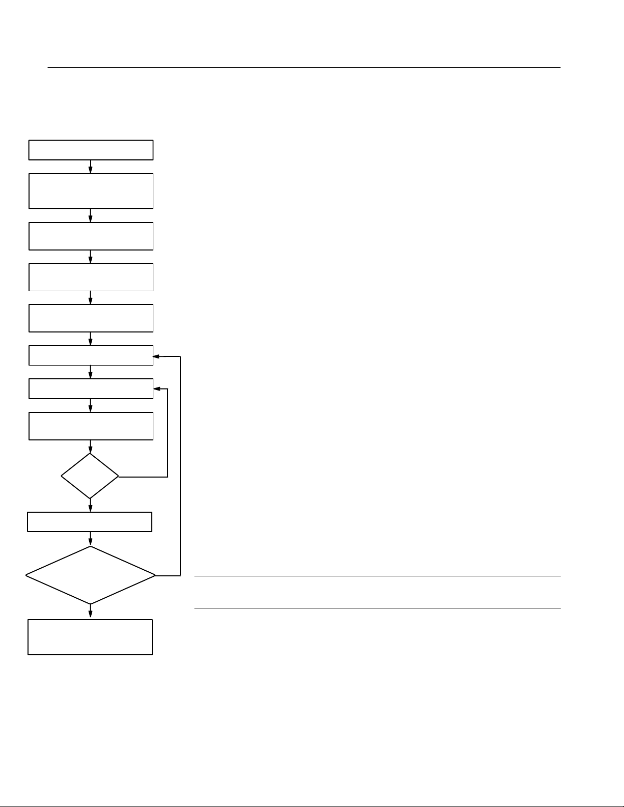
1. Connect the equipment as shown in Figure 2–6.
2. Set all of the User Configuration switches to “open” except for S1–7 (for
channel 1).
3. Set all S14 switches “closed.”
4. Set the ECO 422 to Primary Sync Source.
5. Set the ECO 422 Auto Switching to “Switch on Fault.”
6. Set the step attenuator to 0 dB of attenuation.
7. Rotate potentiometer R265 fully. (You are attempting to allow the minimum
signal level to pass through before the threshold is reached.)
8. Press the fault indicator Reset button. (This clears any errors.)
9. Check the fault indicator for an error indication on either the Primary or
Backup channels. If there are no faults, then proceed to the next step.
Otherwise, try rotating the potentiometer in the other direction. (You are
trying to get the minimum signal level to pass through before reaching the
switching threshold.)
10. Set the step attenuator to 3 dB of attenuation (or whatever attenuation is
required for your application).
9
Any faults
indicated?
no
Set the step attenuator to 3 dB.
Adjust R265 until the Sync Source
changes and a fault is indicated on
10
11
Did the Sync Source
change or was a fault
indicated on the
Primary?
no
12
the Primary.
yes
Figure 2–7: Flowchart for Adjusting R265
11. Check to see that the sync source has not changed to Backup and no faults
are on the Primary channel.
12. Slowly adjust R265 until the ECO 422 switches to the Backup sync source
and a fault occurs on the Primary channel. Press Reset to verify that the fault
is still preset. If the Primary fault indicator LED goes out, continue adjusting
the potentiometer. If the LED remains on, S1–7 through S11–7 are set for
your user-defined level.
yes
NOTE. If you cannot adjust R265 satisfactorily, try inserting the attenuator (close
S1–8) and repeat the adjustment steps from the beginning.
Adjust R266 in the same manner to set a user-defined level for S1–6 through
S11–6.
2–10
ECO 422
Page 43

Specifications
Page 44

Page 45

Specifications
Introduction
The items listed in the following tables describe the performance of the ECO 422
Changeover Unit. Performance Requirements are generally quantitative and can
be tested by a Performance Verification procedure contained in the service part of
this manual.
Supplemental Information is valuable data pertaining to the operation and output
capabilities of this instrument. Only a few items listed in this category may be
tested in the Performance Verification procedure.
Performance Conditions – The requirements listed in the electrical specification
apply over an ambient temperature range of 0_ C to +40_ C. The rated accuracies are valid when the instrument is calibrated at an ambient temperature range
of +20_ C to +30_ C, after a warm-up time of 20 minutes. Test equipment used
to verify Performance Requirements must be calibrated and working within the
limits specified under the Equipment Required list.
These instruments are intended to operate from an AC power source that will not
apply more than 250 V
conductor and ground. A protective ground connection by way of the grounding
conductor is essential for safe operation.
between the supply conductors or either supply
RMS
Environmental specifications are listed toward the back of the following tables.
In addition a list of appropriate safety and electromagnetic interference (EMI)
standards also can be found there.
ECO 422
3–1
Page 46

Specifications
T able 3–1: General Characteristics
Performance
Characteristics
Return Loss
All Inputs and Outputs
Insertion Loss 0.2 dB, DC to 10 MHz
Maximum Switched
Voltage
Maximum Switched
Current
Crosstalk (unselected input to
output or channel to channel)
Relay Switch Time Time that it takes for the
Requirements
Supplemental
Information
30 dB, 0 to 10 MHz
15 dB, 10 to 270 MHz
12 dB at 360 MHz (15 dB
typical)
when selected
0.5 dB, 10 to 200 MHz
1.0 dB, 200 to 360 MHz
±5 V
100 mA
–60 dB to 10 MHz
–30 dB to 200 MHz
–15 dB to 360 MHz
relays to switch and settle.
Approximately 10 msec.
3–2
ECO 422
Page 47

T able 3–2: Signal Loss Detection
Specifications
Performance
Characteristics
Input Signal Switching Level within: These are the defined
NTSC Black Burst
(sync level)
PAL Black Burst
(sync level)
Serial Digital Video
(NTSC Composite)
Serial Digital Video
(Component)
Serial Digital Audio 630 to 790 mV 710 mV 13 &
User Adjustable –100 to –700 mV
Requirements
–180 to –230 mV –200 mV 2 & 4
–190 to –240 mV –210 mV 3 & 5
450 to 630 mV 540 mV (between 2 and
450 to 630 mV 540 mV (between 2 and
Supplemental
Information
switching thresholds set
with the internal Channel
Configuration switch.
Between 2 and 4 dB down
from nominal.
5 dB down)
5 dB down)
Using the two user-defined
Channel Configuration
switches.
Per.
Ver.
10 &
11
7 & 8
14
–700 to –3500 mV
Attenuation approximately x5
Using the user-defined
Channel Configuration
switch with the attenuator
on.
ECO 422
3–3
Page 48

Specifications
T able 3–3: Power Supply
Performance
Characteristics
External Power
Voltage
Input Frequency
Range
Power Consumption
Supply Accuracy
+5 V
–5 V
Hum
+5 V
–5 V
Noise
+5 V
–5 V
Crest Factor w1.35
Fuse Required 1 ampere medium blow fuse
Requirements
90 to 250 VAC Full range, no selector
Supplemental
Information
48 Hz to 62 Hz
20 Watts, typical
+5 V ±200 mV
–5 V ±200 mV
Typical values:
10 mV
10 mV
(5 MHz measurement bandwidth)
v50 mV
v50 mV
for all applications.
T able 3–4: Mechanical (Physical) Characteristics
Characteristics Supplemental Information
Rackmount Dimensions
Height
Width
Length
Net Weight 10.8 lbs (4.9 kg)
Shipping Weight 18 lbs, 5 oz (8.3 kg)
1.734 inches (4.4 cm)
19.0 inches (48.3 cm)
22.1 inches (56.1 cm)
3–4
ECO 422
Page 49

T able 3–5: Environmental Characteristics
Characteristics Supplemental Information
Temperature
Nonoperating
Operating
Altitude
Nonoperating
Operating
Humidity 5 – 95% humidity, noncondensing
Vibration
Operating
–40_ C to +65_ C
0_ C to +50_ C IEC 1010-1 compliance to
_ C.
+40
to 40,000 feet
to 10,000 feet (4572 meters) IEC 1010-1
compliance to 2000 meters.
From 5 to 350 Hz: 0.0002 g2/Hz Acceleration
Power Spectral Density (APSD).
From 350 to 500 Hz: –3 dB/Octave Slope.
At 500 Hz: 0.00014 g2/Hz APSD.
0.31 overall GRMS.
10 minutes/axis.
Specifications
Nonoperating
Shock (nonoperating) Half Sine Wave Shock levels: 50 g’s (instru-
Transportation Qualified under NTSB Test Procedure 1A,
Vehicle Vibration (Random V ibration) Vibrate along all three aces at an overall
Second Manual Handling (Shock) Drop on all sides once from a height of
Equipment Type Measurement
Equipment Class Class I (grounded product), as defined in IEC
Installation Category Installation Category II, as defined in IEC
From 5 to 100 Hz: 0.020 g2/Hz (APSD).
From 100 to 200 Hz: –3 dB/Octave Slope.
From 200 to 350 Hz: 0.010 g2/Hz APSD.
From 350 to 500 Hz: –3 dB/Octave Slope.
At 500 Hz: 0.007 g2/Hz APSD.
2.46 overall GRMS.
10 minutes/axis.
ment), 11 msec duration, 3 shocks per
direction.
Category II (24-inch drop).
vibration level of 1.33 GRMS. One hour per
axis.
24 inches. Drop on the bottom from a height
of 48 inches.
1010-1, Annex H.
1010-1, Annex J. Rated for indoor use only.
ECO 422
Pollution Degree Pollution Degree 2, as defined in IEC 1010-1.
3–5
Page 50

Specifications
Certification
EMI Standards
The following safety standards apply to the ECO 422:
H UL3111-1 – Standard for Electrical Measuring and Test Equipment
H ANSI/ISA S82 – Safety Standard for Electrical and Electronic Test,
Measuring, Controlling, and Related Equipment
H IEC1010-1 – Safety Requirements for Electronic Equipment for Measure-
ment, Control, and Laboratory Use
H CAN/CSA C22.2 No. 1010.1-92 – Safety Requirements for Electrical
Equipment for Measurement, Control, and Laboratory Use
The following electromagnetic interference (EMI) standard applies to the
ECO 422:
H FCC EMI Compatibility – FCC Rules Part 15 Subpart J, Class A
Refer to the compliance declaration in the front of this manual for a list of other
standards.
3–6
ECO 422
Page 51

WARNING
The following servicing instructions are for use only by qualified personnel. To
avoid injury, do not perform any servicing other than that stated in the operating
instructions unless you are qualified to do so. Refer to all Safety Summaries before
performing any service.
Page 52

Page 53

Theory of Operation
Page 54

Page 55

Theory of Operation
Introduction
This section provides information on how the ECO 422 circuitry works, in order
to troubleshoot the instrument.
Logic Conventions
Signal names are all capital letters. For example, SIGNAL.
An active low signal (normally denoted by an overscore) is a signal name
enclosed in parentheses. For example, (SIGNAL).
The aside of a signal name is always in square brackets. For example, [SIG-
NAL].
The aside of an active-low signal is the signal name in parentheses and then
enclosed in square brackets. For example, [(SIGNAL)].
ECO 422 Block Level Description (See Figure 4–1)
Figure 4–1: Block Diagram of the ECO 422
ECO 422
4–1
Page 56

Theory of Operation
The Primary and Backup signals enter through the BNCs. The signal goes
directly to the Relay where one switches through to the rear-panel Output and the
other terminates in 75 W. The rest of the circuitry determines which signal goes
to the Output.
A copy of the Primary and Backup signals go to the Primary and Backup Check
circuitry. This block consists of a peak detector that compares the peak level of
the incoming signal with a predefined level from the Reference Voltage
Generator that is selected by the Voltage Selector. The result of this check is
ANDed with the results from the ten other input sets and sent to the Decision
Logic circuit that determines the state of the relays. Additional circuitry runs the
Alarm Driver for the remote output and the fault indicators on the front panel.
ECO 422 Detailed Circuit Description
Input and Comparators
PRIMARY
INPUT
RELAY_DRIVER
BACKUP
INPUT
2
through
7
The Input and Comparator circuit takes the input signals, selects between them,
and prepares the peak signals for the Decision Logic circuit. There are five input
signal sets on the Main board and six input signal sets on the Connector board.
All of the Input and Comparator circuits are identical for each signal set,
therefore only Channel 1 (on the Connector board) is discussed.
(P_AND)
(P_TEST1)
(B_AND)
(B_TEST1)
OUTPUT
INPUT
BUFFER
INPUT
BUFFER
NEGATIVE
PEAK
DETECTOR
VREF
NEGATIVE
PEAK
DETECTOR
Figure 4–2: Block Diagram of the Input Comparator
4–2
RF Relay . The Primary input signal connects to 75 W BNC, J17. The signal
passes through a 75 W microstrip to the RF relay, K6. Meanwhile the Backup
signal enters J16 and connects to the other side of relay K6 also through a 75 W
microstrip. This relay switches the signal to either two 37.5 W resistors in series
for 75 W termination, or to the J18 output BNC. A 1.5 kW resistor (R262 for
ECO 422
Page 57

Theory of Operation
Primary and R261 for Backup) AC coupled with 47 and 0.01 F parallel
capacitors (C194 and C132 for Primary and C195 and C131 for Backup) samples
the input signals. This signal then goes to the Input Buffer.
Input Buffers. The Emitter-follower Input Buffer (Q32 for Primary and Q33 for
Backup) reduces the input capacitance that could degrade the return loss at high
frequencies. The signal may be attenuated by Q36 for the Primary circuit and
Q37 for the Backup circuit. If the ATTEN1 from the Selector Switch signal is
high, it turns on the transistor that reduces the amplitude of the signal. This
allows checking a broader range of signals without the Negative Peak Detectors
being overdriven or saturated. The output of the Input Buffers goes to the
Negative Peak Detectors.
Negative Peak Detectors. The Negative Peak Detector circuit begins with a
transistor that inverts the input signal. The Peak Detector circuit picks off the
input signal peaks, which charge the memory capacitor, C140 or C139. When no
peaks are present, the memory capacitor is discharged by R260 or R259. The DC
output of the peak detector is buffered by a low drift op-amp, U11A and B.
Control and Remote
V oltage Comparator. The Voltage Comparator takes the output of the Negative
Peak Detector and compares it to a DC reference voltage, VREF1, selected from
eight possible choices: off, five presets, or two user-defined values. When the
input negative peaks generate a voltage less than the selected reference, the
output of the comparator goes low, signaling a fault to the control circuit. The
resulting signal is (P_AND_C) for the Primary and (B_AND_C) for the Backup.
(P_TEST1) and (B_TEST1) are only for automated testing purposes. All the
Primary signals are wire-ANDed together as the (P_AND_C) signal and sent to
the Main board via J19. The same is done with all the Backup signals.
8
The Primary and Backup signals from the Voltage Comparators on the Main
board are ANDed with like signals coming from the Connector board and passed
to the Controller PLD that then generates the control signals for the switching
relays.
ECO 422
4–3
Page 58

Theory of Operation
Figure 4–3: Block Diagram for the Control and Remote Circuit
Keyboard Encoder. The front panel is connected to the Main board through J16.
The input from the front panel is scanned by the Keyboard encoder, U11. The
outputs are active high and chosen so that only one can be active at a time. The
KEY_VALID signal is ANDed with each output inside the controller to provide
switch debouncing.
Front-panel LED Driver. U12 outputs the signals to drive the LEDs on the front
panel. It drives the LEDs to +5 V.
U12 outputs the signals to driver the LEDs on the front panel. It drives the LEDs
to +5 V. The timer, U13, provides the pulsing necessary to flash the front-panel
fault LEDs and clock the front panel Time Out circuit in the Controller. When
(TIMER_DIS) is low, the timer is prevented from pulsing. When the input goes
high, the timer output goes low, turning on and allowing the Controller to flash
the LEDs.
Remote. The Remote port, J17, provides three inputs and four outputs from the
Controller. (R_AUTO) controls auto switching, (R_SOURCE) is a manual
source switch, and (R_RESET) resets the fault indicator LEDs. These signals are
buffered by U18B that is always enabled. The input has six diodes for ESD
protection.
4–4
The buffer drives the two input source light outputs through resistors to ground
because there is no remote power on the rear-panel connector. The inversion of
ECO 422
Page 59

Theory of Operation
the select lines is accomplished by cross wiring P_LED and B_LED, through the
buffer to (B_O) and (P_O), which are complimentary.
The high current (ALARM) output is provided by Q32 and a high wattage 22 W
resistor. A 10 kW pull-down is provided for test purposes.
The fault reporting output, U15 and Q33, provide a method of fault indication
that also includes remote indication of instrument failure. A 24 V, 20 mA current
limited input and ground are connected to J17–2 and J17–4. When the controller
detects an input fault or suffers a power failure, the LED in U15 shuts off. The
transistor opens up allowing Q33 to saturate to less than 1.5 V, signaling the
fault. When the LED is on, Q33 is cut off leaving less than 100 nA of leakage.
The diodes, CR48 and VR1, are provided for reverse voltage and ESD protection.
Controller. The Controller has five main functions:
H Encode the keyboard signals.
H Send the correct signals to the LED Driver.
H Generate the ALARM signal for the Remote circuit.
H Generate the Switch or Auto Switch command.
H Keep track of the Time Out circuit.
The five inputs from the Keyboard Encoder enter the Controller. KEY_VALID is
internally delayed three clock cycles to allow key data setup. The ENABLE and
the delayed KEY_VALID signal clock a toggle flip–flop high to enable the three
input gates. Once enabled, the combination of delayed KEY_VALID and each
input produces a control signal for the Controller LED Driver circuit, the
Lockout circuit, and the Fault circuit.
The fault block of the Controller uses four input signals (PFAULT), (BFAULT),
(TIMER), and RESET. These signals determine whether the (ALARM) signal
needs to be sent to the Remote, if the Primary or Backup front panel Alarm
LEDs should be on, and if the auto switch function should be activated. The
RESET command turns off the LEDs and the Remote Alarm output. The
(TIMER) signal is NANDed with the LED fault signal to make it flash.
The automatic source change with fault detection function is enabled by the
(AUTO_O) signal from the Keyboard Encoder circuitry. This signal and some
other controls generate (AUTO_ON). (AUTO_ON) can be switched off by the
(R_AUTO) control from the rear-panel Remote connector. The (AUTO_ON)
signal is also used to derive the (P_SELECT) and (B_SELECT) signals.
(AUTO_ON) and (AUTO_OFF) are sent to drive the front-panel LED circuit.
ECO 422
After the front panel is enabled, the ECO 422 will only allow the front panel
approximately 60 seconds of inactivity before it will automatically disable the
4–5
Page 60

Theory of Operation
front panel. The Controller gets a timing signal from the Timer circuit. It counts
this signal to check the inactivity of the front panel. Every time that a front-panel
key is pressed the internal counter is reset. If the counter reaches one minute, the
front panel is automatically locked out.
Reference Voltage and Selector Switch Farm
+12 V
Figure 4–4: Reference V oltage and Selector Switch Farm Block Diagram
Reference V oltages. The +2.5 V reference voltage is provided by U31. This
signal is used to produce the –2.5V_REF and the Attenuation signals.
9
VREF
for each
channel
+5 V
4–6
The +2.5 V signal from U31 is combined with ATTEN_SW and buffered by
U23B and U20B. The resulting signal is set to the Switch Farm as ATTEN_M
and ATTEN_C to control the input attenuators.
The –5 V signal is inverted and buffered by U20A, resulting in the –2.5V_REF
signal. This signal drives five inverting amplifiers, each with a DC output
equivalent to the recovered DC from the Peak Detector Buffers for a specific
type of input. It also drives two adjustable amplifiers whose amplitude is
adjusted by R266 and R265. The results are the BUFX signals that are connected
to the Switch Farm by S14–1 through S14–7.
Switch Farm. The Switch Farm, S1–S11, is a set of 11 eight-bit DIP switches, one
for each channel. The user selects which reference amplifier, VREF, for each
channel using the switches and whether or not the attenuator, ATTEN, is
inserted. Opening the seven reference amplitude switches allows VREF to go to
ECO 422
Page 61

Theory of Operation
a negative voltage. Since the peak detector will never produce a negative voltage,
the comparators will be disabled.
Post Regulated Power
Supply
Power is supplied to the Main and Connector boards through J21 from an OEM
supply which provides +15 V, –15 V and +5 V logic level voltage. The 15 V
supplies are regulated to +5 and –5 V. The +15 V is reduced by 22 W resistors
and then used directly by the relay.
NOTE. There are two
panel and the other is on the power supply. Make sure to check the internal fuse
if the instrument will not power up.
fuses in the instrument. One is accessible through the rear
ECO 422
4–7
Page 62

Theory of Operation
4–8
ECO 422
Page 63

Performance Verification
Page 64

Page 65

Performance Verification
Introduction
This section consists of checklists and detailed procedures to use in verifying
performance parameters and adjusting it to within tolerances.
The order of these procedures has been chosen to minimize changes in equipment setups. Performance parameters may be checked in any order.
Calibration Data Report
The Calibration Data Report that follows can be used to document instrument
performance. In addition, it can be used as a short-form Performance Check for
those familiar with the Performance Verification Procedure. Only steps that have
numeric Performance Requirements are included in this report form. (Some steps
have been omitted.)
ECO 422
5–1
Page 66

Performance Verification
Calibration Data Report
Instrument ECO 422 Cal. Date
Serial Number
Certificate Number
1
Technician
Procedure 070–8472–00 Revision Date
MINIMUM
STEP OPERATION
1 Overall Switching Disabled
Channel 1:
2 NTSC Black Burst Switch – Primary switch at 2 dB down switch at 4 dB down
4 NTSC Black Burst Switch – Backup switch at 2 dB down switch at 4 dB down
3 PAL Black Burst Switch – Primary switch at 2 dB down switch at 4 dB down
5 PAL Black Burst Switch – Backup switch at 2 dB down switch at 4 dB down
7 Serial Digital Component Switch –
Primary
8 Serial Digital Component Switch –
Backup
10 NTSC Serial Digital Composite
Switch – Primary
11 NTSC Serial Digital Composite
Switch – Backup
13 Serial Digital Audio Switch – Primary switch at 2 dB down switch at 4 dB down
14 Serial Digital Audio Switch – Backup switch at 2 dB down switch at 4 dB down
Channel 2: (swap S2 for S1)
2 NTSC Black Burst Switch – Primary switch at 2 dB down switch at 4 dB down
4 NTSC Black Burst Switch – Backup switch at 2 dB down switch at 4 dB down
3 PAL Black Burst Switch – Primary switch at 2 dB down switch at 4 dB down
5 PAL Black Burst Switch – Backup switch at 2 dB down switch at 4 dB down
7 Serial Digital Component Switch –
Primary
8 Serial Digital Component Switch –
Backup
10 NTSC Serial Digital Composite
Switch – Primary
11 NTSC Serial Digital Composite
Switch – Backup
13 Serial Digital Audio Switch – Primary switch at 2 dB down switch at 4 dB down
14 Serial Digital Audio Switch – Backup switch at 2 dB down switch at 4 dB down
TOLERANCE
switch at 2 dB down switch at 5 dB down
switch at 2 dB down switch at 5 dB down
switch at 2 dB down switch at 5 dB down
switch at 2 dB down switch at 5 dB down
switch at 2 dB down switch at 5 dB down
switch at 2 dB down switch at 5 dB down
switch at 2 dB down switch at 5 dB down
switch at 2 dB down switch at 5 dB down
MAXIMUM
TOLERANCE
INCOMING OUTGOING
5–2
1
Certificate number is not provided, unless ”Certificate of Traceability” is issued.
ECO 422
Page 67

Performance Verification
MINIMUM
STEP OUTGOINGINCOMING
Channel 3: (swap S3 for S1)
2 NTSC Black Burst Switch – Primary switch at 2 dB down switch at 4 dB down
4 NTSC Black Burst Switch – Backup switch at 2 dB down switch at 4 dB down
3 PAL Black Burst Switch – Primary switch at 2 dB down switch at 4 dB down
5 PAL Black Burst Switch – Backup switch at 2 dB down switch at 4 dB down
7 Serial Digital Component Switch –
Primary
8 Serial Digital Component Switch –
Backup
10 NTSC Serial Digital Composite
Switch – Primary
11 NTSC Serial Digital Composite
Switch – Backup
13 Serial Digital Audio Switch – Primary switch at 2 dB down switch at 4 dB down
14 Serial Digital Audio Switch – Backup switch at 2 dB down switch at 4 dB down
Channel 4: (swap S4 for S1)
2 NTSC Black Burst Switch – Primary switch at 2 dB down switch at 4 dB down
4 NTSC Black Burst Switch – Backup switch at 2 dB down switch at 4 dB down
3 PAL Black Burst Switch – Primary switch at 2 dB down switch at 4 dB down
5 PAL Black Burst Switch – Backup switch at 2 dB down switch at 4 dB down
7 Serial Digital Component Switch –
Primary
8 Serial Digital Component Switch –
Backup
10 NTSC Serial Digital Composite
Switch – Primary
11 NTSC Serial Digital Composite
Switch – Backup
13 Serial Digital Audio Switch – Primary switch at 2 dB down switch at 4 dB down
14 Serial Digital Audio Switch – Backup switch at 2 dB down switch at 4 dB down
Channel 5: (swap S5 for S1)
2 NTSC Black Burst Switch – Primary switch at 2 dB down switch at 4 dB down
4 NTSC Black Burst Switch – Backup switch at 2 dB down switch at 4 dB down
3 PAL Black Burst Switch – Primary switch at 2 dB down switch at 4 dB down
5 PAL Black Burst Switch – Backup switch at 2 dB down switch at 4 dB down
7 Serial Digital Component Switch –
Primary
OPERATION
TOLERANCE
switch at 2 dB down switch at 5 dB down
switch at 2 dB down switch at 5 dB down
switch at 2 dB down switch at 5 dB down
switch at 2 dB down switch at 5 dB down
switch at 2 dB down switch at 5 dB down
switch at 2 dB down switch at 5 dB down
switch at 2 dB down switch at 5 dB down
switch at 2 dB down switch at 5 dB down
switch at 2 dB down switch at 5 dB down
MAXIMUM
TOLERANCE
ECO 422
5–3
Page 68

Performance Verification
MINIMUM
STEP OUTGOINGINCOMING
8 Serial Digital Component Switch –
Backup
10 NTSC Serial Digital Composite
Switch – Primary
11 NTSC Serial Digital Composite
Switch – Backup
13 Serial Digital Audio Switch – Primary switch at 2 dB down switch at 4 dB down
14 Serial Digital Audio Switch – Backup switch at 2 dB down switch at 4 dB down
Channel 6: (swap S6 for S1)
2 NTSC Black Burst Switch – Primary switch at 2 dB down switch at 4 dB down
4 NTSC Black Burst Switch – Backup switch at 2 dB down switch at 4 dB down
3 PAL Black Burst Switch – Primary switch at 2 dB down switch at 4 dB down
5 PAL Black Burst Switch – Backup switch at 2 dB down switch at 4 dB down
7 Serial Digital Component Switch –
Primary
8 Serial Digital Component Switch –
Backup
10 NTSC Serial Digital Composite
Switch – Primary
11 NTSC Serial Digital Composite
Switch – Backup
13 Serial Digital Audio Switch – Primary switch at 2 dB down switch at 4 dB down
14 Serial Digital Audio Switch – Backup switch at 2 dB down switch at 4 dB down
Channel 7: (swap S7 for S1)
2 NTSC Black Burst Switch – Primary switch at 2 dB down switch at 4 dB down
4 NTSC Black Burst Switch – Backup switch at 2 dB down switch at 4 dB down
3 PAL Black Burst Switch – Primary switch at 2 dB down switch at 4 dB down
5 PAL Black Burst Switch – Backup switch at 2 dB down switch at 4 dB down
7 Serial Digital Component Switch –
Primary
8 Serial Digital Component Switch –
Backup
10 NTSC Serial Digital Composite
Switch – Primary
11 NTSC Serial Digital Composite
Switch – Backup
13 Serial Digital Audio Switch – Primary switch at 2 dB down switch at 4 dB down
14 Serial Digital Audio Switch – Backup switch at 2 dB down switch at 4 dB down
OPERATION
TOLERANCE
switch at 2 dB down switch at 5 dB down
switch at 2 dB down switch at 5 dB down
switch at 2 dB down switch at 5 dB down
switch at 2 dB down switch at 5 dB down
switch at 2 dB down switch at 5 dB down
switch at 2 dB down switch at 5 dB down
switch at 2 dB down switch at 5 dB down
switch at 2 dB down switch at 5 dB down
switch at 2 dB down switch at 5 dB down
switch at 2 dB down switch at 5 dB down
switch at 2 dB down switch at 5 dB down
MAXIMUM
TOLERANCE
5–4
ECO 422
Page 69

Performance Verification
MINIMUM
STEP OUTGOINGINCOMING
Channel 8: (swap S8 for S1)
2 NTSC Black Burst Switch – Primary switch at 2 dB down switch at 4 dB down
4 NTSC Black Burst Switch – Backup switch at 2 dB down switch at 4 dB down
3 PAL Black Burst Switch – Primary switch at 2 dB down switch at 4 dB down
5 PAL Black Burst Switch – Backup switch at 2 dB down switch at 4 dB down
7 Serial Digital Component Switch –
Primary
8 Serial Digital Component Switch –
Backup
10 NTSC Serial Digital Composite
Switch – Primary
11 NTSC Serial Digital Composite
Switch – Backup
13 Serial Digital Audio Switch – Primary switch at 2 dB down switch at 4 dB down
14 Serial Digital Audio Switch – Backup switch at 2 dB down switch at 4 dB down
Channel 9: (swap S9 for S1)
2 NTSC Black Burst Switch – Primary switch at 2 dB down switch at 4 dB down
4 NTSC Black Burst Switch – Backup switch at 2 dB down switch at 4 dB down
3 PAL Black Burst Switch – Primary switch at 2 dB down switch at 4 dB down
5 PAL Black Burst Switch – Backup switch at 2 dB down switch at 4 dB down
7 Serial Digital Component Switch –
Primary
8 Serial Digital Component Switch –
Backup
10 NTSC Serial Digital Composite
Switch – Primary
11 NTSC Serial Digital Composite
Switch – Backup
13 Serial Digital Audio Switch – Primary switch at 2 dB down switch at 4 dB down
14 Serial Digital Audio Switch – Backup switch at 2 dB down switch at 4 dB down
Channel 10: (swap S10 for S1)
2 NTSC Black Burst Switch – Primary switch at 2 dB down switch at 4 dB down
4 NTSC Black Burst Switch – Backup switch at 2 dB down switch at 4 dB down
3 PAL Black Burst Switch – Primary switch at 2 dB down switch at 4 dB down
5 PAL Black Burst Switch – Backup switch at 2 dB down switch at 4 dB down
7 Serial Digital Component Switch –
Primary
OPERATION
TOLERANCE
switch at 2 dB down switch at 5 dB down
switch at 2 dB down switch at 5 dB down
switch at 2 dB down switch at 5 dB down
switch at 2 dB down switch at 5 dB down
switch at 2 dB down switch at 5 dB down
switch at 2 dB down switch at 5 dB down
switch at 2 dB down switch at 5 dB down
switch at 2 dB down switch at 5 dB down
switch at 2 dB down switch at 5 dB down
MAXIMUM
TOLERANCE
ECO 422
5–5
Page 70

Performance Verification
MINIMUM
STEP OUTGOINGINCOMING
8 Serial Digital Component Switch –
Backup
10 NTSC Serial Digital Composite
Switch – Primary
11 NTSC Serial Digital Composite
Switch – Backup
13 Serial Digital Audio Switch – Primary switch at 2 dB down switch at 4 dB down
14 Serial Digital Audio Switch – Backup switch at 2 dB down switch at 4 dB down
Channel 1 1: (swap S11 for S1)
2 NTSC Black Burst Switch – Primary switch at 2 dB down switch at 4 dB down
4 NTSC Black Burst Switch – Backup switch at 2 dB down switch at 4 dB down
3 PAL Black Burst Switch – Primary switch at 2 dB down switch at 4 dB down
5 PAL Black Burst Switch – Backup switch at 2 dB down switch at 4 dB down
7 Serial Digital Component Switch –
Primary
8 Serial Digital Component Switch –
Backup
10 NTSC Serial Digital Composite
Switch – Primary
11 NTSC Serial Digital Composite
Switch – Backup
13 Serial Digital Audio Switch – Primary switch at 2 dB down switch at 4 dB down
14 Serial Digital Audio Switch – Backup switch at 2 dB down switch at 4 dB down
OPERATION
TOLERANCE
switch at 2 dB down switch at 5 dB down
switch at 2 dB down switch at 5 dB down
switch at 2 dB down switch at 5 dB down
switch at 2 dB down switch at 5 dB down
switch at 2 dB down switch at 5 dB down
switch at 2 dB down switch at 5 dB down
switch at 2 dB down switch at 5 dB down
MAXIMUM
TOLERANCE
Equipment Required
5–6
Signal Source – SPG 422. Must be able to generate black burst signal (NTSC
and PAL), serial digital video (component), and serial digital audio. Also
requires two outputs of each signal.
Signal Source – TSG 170D option 1S. Must be able to output serial digital
composite video.
Step Attenuator – The step attenuator must be able to attenuate a signal at least
60 dB and step from 1 to 4 dB in 0.5 dB steps. (Example: 847 Attenuator from
KAY Elemetrics Corp.)
Oscilloscope or waveform monitor. Used only to monitor the signals. (Examples:
11000 series oscilloscope or 1780 Waveform Monitor.)
ECO 422
Page 71

75 W terminators. (Example: Tektronix part number 011-0102-00 or
011-0102-01)
75 W Cables. (Example: Tektronix part number 012-0074-00)
Performance V erification Procedure
Signal Checking Disabled
1. Check Overall Switching Disabled
Disconnect all signals (if any) from the ECO 422 and power down the
instrument.
Set all switches on S1 through S11 to “open” to disable switches on all
channels.
Power the ECO 422 up. (No inputs or outputs are required at this point.)
Performance Verification
Black Burst Checks
CHECK – that there are no error shown on the front panel.
2. NTSC Black Burst Check for Channel 1 Primary
Switch between 2 and 4 dB down from nominal
Connect the equipment as shown in Figure 5–1.
ECO 422
5–7
Page 72

Performance Verification
Figure 5–1: Setup to Check Black Burst Levels
Power down all equipment.
Set the Channel Configuration switches to Disabled (signal not checked) for
all channels (set all DIP switches on S1 through S11 to “open”).
Set the Channel Configuration switch to NTSC Black Burst for Channel 1
(set S1–1 to “closed” and S1–2 through S1–8 “open”).
Set the step attenuator to 0 dB of attenuation.
Power up all equipment.
Set the SPG 422 to output an NTSC black burst signal.
CHECK – that there are no errors shown for either the Primary or Backup
ECO 422 sync sources.
Set the ECO 422 to “Primary” Sync Source and Auto Switch “Switch on
Fault.”
Add attenuation, 0.5 dB at a time, to the Primary input signal until the signal
source switches to the Backup.
5–8
Press the Reset button on the front panel and try to return the signal source
to Primary.
ECO 422
Page 73

Performance Verification
CHECK – that the Primary signal still shows an error and automatically
switches back to Backup. If the ECO 422 doesn’t continue to show the
Primary signal in error after the reset, continue adding attenuation until the
Primary signal switches to Backup again.
Note the attenuation of the step attenuator.
CHECK – that the ECO switches between 2 and 4 dB down.
3. PAL Black Burst Check for Channel 1 Primary
Switch between 2 and 4 dB down from nominal
Connect the equipment as shown in Figure 5–1.
Set the Channel Configuration switches to Disabled (signal not checked) for
all channels (set all the DIP switches on S2 through S11 to “open”).
Set the Channel Configuration switch to PAL Black Burst for Channel 1 (set
S1–1 to “open,” S1–2 “closed,” and S1–3 through S1–8 “open”).
Set the step attenuator to 0 dB of attenuation.
Set the SPG 422 to output a PAL black burst signal.
Press Reset.
CHECK – that there are no errors shown for either the Primary or Backup
ECO 422 sync sources.
Set the ECO 422 to “Primary” Sync Source and Auto Switch “Switch on
Fault.”
Add attenuation, 0.5 dB at a time, to the Primary input signal until the signal
source switches to the Backup.
Press the Reset button on the front panel and try to return the signal source
to Primary.
CHECK – that the Primary signal still shows an error and automatically
switches back to Backup. If the ECO 422 does not continue to show the
Primary signal in error after the reset, continue adding attenuation until the
Primary signal switches to Backup again.
Note the attenuation of the step attenuator.
CHECK – that the ECO switches between 2 and 4 dB down.
4. NTSC Black Burst Check for Channel 1 Backup
Switch between 2 and 4 dB down from nominal
ECO 422
Connect the equipment as shown in Figure 5–1, except swap the Primary and
Backup input signals so that the step attenuator is on the Backup channel.
5–9
Page 74

Performance Verification
Set the Channel Configuration switches to Disabled (signal not checked) for
all channels (set all the DIP switches on S1 through S11 to “open”).
Set the Channel Configuration switch to NTSC Black Burst for Channel 1
(set S1–1 to “closed” and SW1–2 through S1–8 “open”).
Set the step attenuator to 0 dB of attenuation.
Set the SPG 422 to output an NTSC black burst signal.
Press Reset.
CHECK – that there are no errors shown for either the Primary or Backup
ECO 422 sync sources.
Set the ECO 422 to “Backup” Sync Source and Auto Switch to “Switch on
Fault.”
Add attenuation, 0.5 dB at a time, to the Backup input signal until the signal
source switches to the Primary.
Press the Reset button on the front panel and try to return the signal source
to Backup.
CHECK – that the Backup signal still shows an error and automatically
switches back to Primary. If the ECO 422 does not continue to show the
Backup signal in error after the reset, continue adding attenuation until the
Backup signal switches to Primary again.
Note the attenuation of the step attenuator.
CHECK – that the ECO switches between 2 and 4 dB down.
5. PAL Black Burst Check for Channel 1 Backup
Switch between 2 and 4 dB down from nominal
Connect the equipment as shown in Figure 5–1, except swap the Backup and
Primary input signals so that the step attenuator is on the Backup input
signal.
Set the Channel Configuration switches to Disabled (signal not checked) for
all channels (set all the DIP switches on S2 through S11 to “open”).
Set the Channel Configuration switch to PAL Black Burst for Channel 1 (set
S1–1 to “open,” S1–2 “closed,” and S1–30 through S1–8 “open”).
5–10
Set the step attenuator to 0 dB of attenuation.
Set the SPG 422 to output a PAL black burst signal.
Press Reset.
ECO 422
Page 75

Performance Verification
CHECK – that there are no errors shown for either the Primary or Backup
ECO 422 sync sources.
Set the ECO 422 to “Backup” Sync Source and Auto Switch to “Switch on
Fault.”
Add attenuation, 0.5 dB at a time, to the Backup input signal until the signal
source switches to the Primary.
Press the Reset button on the front panel and try to return the signal source
to Backup.
CHECK – that the Backup signal still shows an error and automatically
switches back to Primary. If the ECO 422 does not continue to show the
Backup signal in error after the reset, continue adding attenuation until the
Backup signal switches to Primary again.
Note the attenuation of the step attenuator.
CHECK – that the ECO switches between 2 and 4 dB down.
Serial Digital Video
Checks
6. Check the NTSC & PAL Black Burst for Channels 2 – 11
Switch between 2 and 4 dB down from nominal
Repeat the four previous procedures for Channels 2 – 11 of the ECO 422.
Move the cables from Channel 1 to the channel under test. Replace the
switch setting for S1 as given in the following Table.
Channel No. Switch No.
2S2
3S3
4S4
5S5
6S6
7S7
8S8
9S9
10 S10
11 S11
7. Serial Digital Component Check for Channel 1 Primary
Switch between 2 and 5 dB down from nominal
ECO 422
Connect the equipment as shown in Figure 5–2.
5–11
Page 76
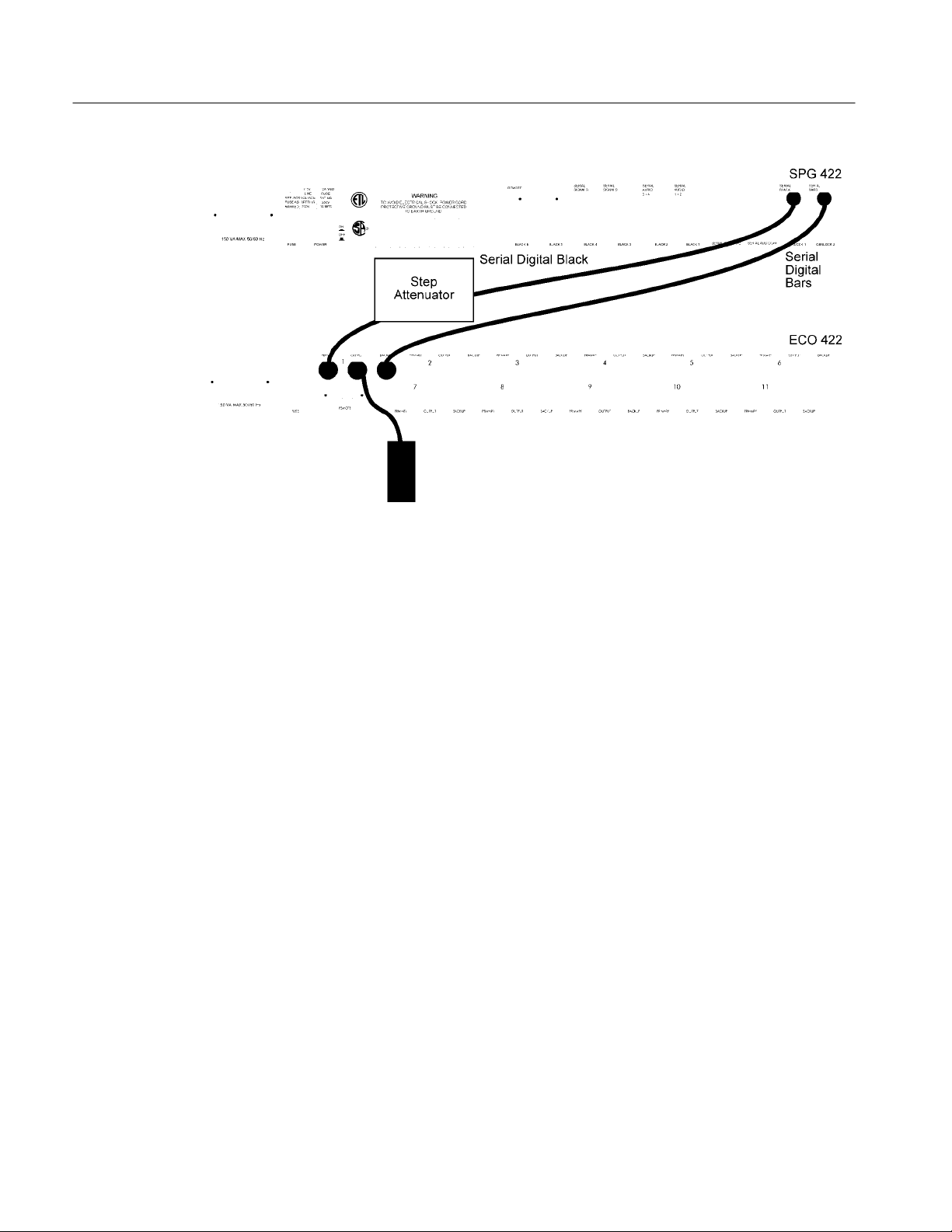
Performance Verification
Figure 5–2: Setup to Check the Component Serial Digital Video Levels
Set the Channel Configuration switches to Disabled (signal not checked) for
all channels (set all the DIP switches on S1 through S11 to “open”).
Set the Channel Configuration switch to Serial Digital Video Component for
Channel 1 (set S1–4 to “closed,” S1–1 through S1–3 “open,” and S1–5
through S1–8 “open”).
Set the step attenuator to 0 dB of attenuation.
Set the SPG 422 to output any serial digital bars signal using either the
525/59.94 or 625/50 standard.
Press Reset.
CHECK – that there are no errors shown for either the Primary or Backup
ECO 422 sync sources.
Set the ECO 422 (using the front panel) to “Primary” Sync Source and Auto
Switch “Switch on Fault.”
Add attenuation, 0.5 dB at a time, to the Primary input signal until the signal
source switches to Backup.
Press the Reset button on the front panel and try to return the signal source
to Primary.
5–12
CHECK – that the Primary signal still shows an error and automatically
switches back to Backup. If the ECO 422 does not continue to show the
Primary signal in error after the reset, continue adding attenuation until the
Primary signal switches to Backup again.
ECO 422
Page 77

Performance Verification
Note the attenuation of the step attenuator.
CHECK – that the ECO switches between 2 and 5 dB down.
Repeat using the 625/50 standard bars signal as the input.
8. Serial Digital Component Check for Channel 1 Backup
Switch between 2 and 5 dB down from nominal
Connect the equipment as shown in Figure 5–2, except swap the Primary and
Backup input signals so that the step attenuator is on the Backup input.
Set the Channel Configuration switches to Disabled (signal not checked) for
all channels (set all the DIP switches on S1 through S11 to “open”).
Set the Channel Configuration switch to Serial Digital Video Component for
Channel 1 (set S1–4 to “closed,” S1–1 through S1–3 “open,” and S1–5
through S1–8 “open”).
Set the step attenuator to 0 dB of attenuation.
Set the SPG 422 to output any serial digital bars signal using either the
525/59.94 or 625/50 standard.
Press Reset.
CHECK – that there are no errors shown for either the Primary or Backup
ECO 422 sync sources.
Set the ECO 422 (using the front panel) to “Backup” Sync Source and Auto
Switch “Switch on Fault.”
Add attenuation, 0.5 dB at a time, to the Backup input signal until the signal
source switches to Primary.
Press the Reset button on the front panel and try to return the signal source
to Backup.
CHECK – that the Backup signal still shows an error and automatically
switches back to Primary. If the ECO 422 does not continue to show the
Backup signal in error after the reset, continue adding attenuation until the
Backup signal switches to Primary again.
Note the attenuation of the step attenuator.
CHECK – that the ECO switches between 2 and 5 dB down.
ECO 422
Repeat using a 625/50 bars signal as the input.
5–13
Page 78
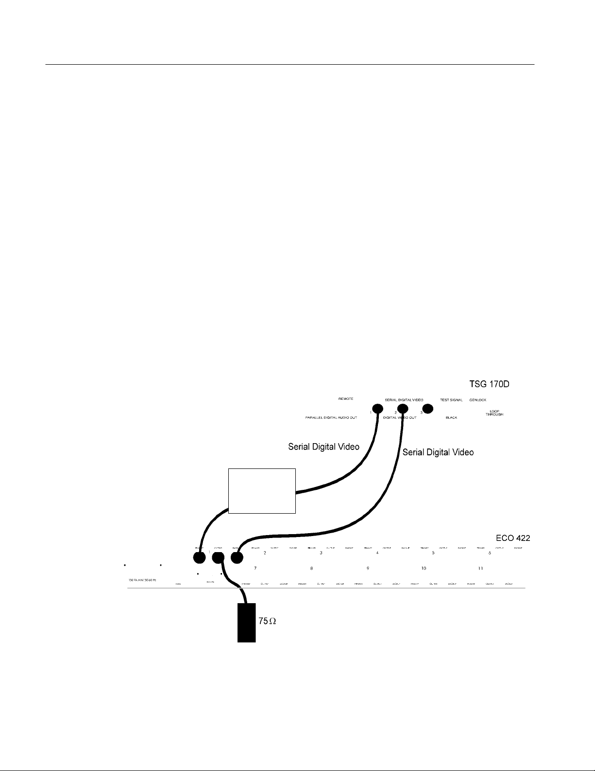
Performance Verification
9. Check Serial Digital Video (Component) for Channels 2 through 11
Switch between 2 and 5 dB down from nominal
Repeat the previous two procedures for Channels 2 through 11 of the ECO
422. Move the cables from Channel 1 to the channel under test. Replace the
switch setting for S1 as given in the following table.
Channel No. Switch No.
2S2
3S3
4S4
5S5
6S6
7S7
8S8
9S9
10 S10
11 S11
10. NTSC Serial Digital Composite Check for Channel 1 Primary
Switch between 2 and 5 dB down from nominal
Connect the equipment as shown in Figure 5–3.
Step
Attenuator
5–14
Figure 5–3: Setup to Check the Serial Digital Video Composite Levels
ECO 422
Page 79

Performance Verification
Set the Channel Configuration switches to Disabled (signal not checked) for
all channels (set all the DIP switches on S1 through S11 to “closed”).
Set the Channel Configuration switch to NTSC Serial Digital Video
Composite for Channel 1 (set S1–3 to “closed,” S1–1 and S1–2 “open,” and
S1–4 through S1–8 “open”).
Set the step attenuator to 0 dB of attenuation.
Set the TSG 170D to output any serial digital signal.
Press Reset.
CHECK – that there are no errors shown for either the Primary or Backup
ECO 422 sync sources.
Set the ECO 422 to “Primary” Sync Source and Auto Switch to “Switch on
Fault.”
Add attenuation, 0.5 dB at a time, to the Primary input signal until the signal
source switches to Backup.
Press the Reset button on the front panel and try to return the signal source
to Primary.
CHECK – that the Primary signal still shows an error and automatically
switches back to Backup. If the ECO 422 does not continue to show the
Primary signal in error after the reset, continue adding attenuation until the
Primary signal switches to Backup again.
Note the attenuation of the step attenuator.
CHECK – that the ECO switches between 2 and 5 dB down.
11. NTSC Serial Digital Composite Check for Channel 1 Backup
Switch between 2 and 5 dB down from nominal
Connect the equipment as shown in Figure 5–3, except swap the Primary and
Backup signals, so that the step attenuator is on the Backup input.
Set the Channel Configuration switches to Disabled (signal not checked) for
all channels (set all the DIP switches on S1 through S11 to “closed”).
Set the Channel Configuration switch to Serial Digital Video Composite for
Channel 1 (set S1–3 to “closed,” S1–1 and S1–2 “open,” and S1–4 through
S1–8 “open”).
ECO 422
Set the step attenuator to 0 dB of attenuation.
Set the TSG 170D to output any serial digital signal. (Do not use the SDI
Check Field signal.)
5–15
Page 80

Performance Verification
Press Reset.
CHECK – that there are no errors shown for either the Primary or Backup
ECO 422 sync sources.
Set the ECO 422 to “Backup” Sync Source and Auto Switch “Switch on
Fault.”
Add attenuation, 0.5 dB at a time, to the Backup input signal until the signal
source switches to Primary.
Press the Reset button on the front panel and try to return the signal source
to Backup.
CHECK – that the Backup signal still shows an error and automatically
switches back to Primary. If the ECO 422 does not continue to show the
Backup signal in error after the reset, continue adding attenuation until the
Backup signal switches to Primary again.
Note the attenuation of the step attenuator.
Serial Digital Audio
Checks
CHECK – that the ECO switches between 2 and 5 dB down.
12. Check Serial Digital Video (Composite) for Channels 2 through 11
Switch between 2 and 5 dB down from nominal
Repeat the previous two procedures for Channels 2 through 11 of the
ECO 422. Move the cables from Channel 1 to the channel under test.
Replace the switch setting for S1 as given in the following table.
Channel No. Switch No.
2S2
3S3
4S4
5S5
6S6
7S7
8S8
9S9
10 S10
11 S11
13. Serial Digital Audio Check for Channel 1 Primary
Switch between 2 and 4 dB down from nominal
5–16
Connect the equipment as shown in Figure 5–4.
ECO 422
Page 81

Performance Verification
Figure 5–4: Setup to Check the Serial Audio Levels
Set the Channel Configuration switches to Disabled (signal not checked) for
all channels (set all the DIP switches on S1 through S11 to “open”).
Set the Channel Configuration switch to Serial Digital Audio for Channel 1
(set S1–5 to “closed,” S1–1 through S1–4 “open,” and S1–6 through S1–8
“open”).
Set the step attenuator to 0 dB of attenuation.
Set the SPG 422 to output either a 1000 or 800 Hz serial digital audio tone
on all four channels.
Press Reset.
CHECK – that there are no errors shown for either the Primary or Backup
ECO 422 sync sources.
Set the ECO 422 to “Primary” Sync Source and Auto Switch to “Switch on
Fault.”
Add attenuation, 0.5 dB at a time, to the Primary input signal until the signal
source switches to Backup.
ECO 422
Press the Reset button on the front panel and try to return the signal source
to Primary.
5–17
Page 82

Performance Verification
CHECK – that the Primary signal still shows an error and automatically
switches back to Backup. If the ECO 422 does not continue to show the
Primary signal in error after the reset, continue adding attenuation until the
Primary signal switches to Backup again.
Note the attenuation of the step attenuator.
CHECK – that the ECO switches between 2 and 4 dB down.
14. Serial Digital Audio Check for Channel 1 Backup
Switch between 2 and 4 dB down from nominal
Connect the equipment as shown in Figure except swap the Primary and
Backup cables so that the attenuator is on the Backup side.
Set the Channel Configuration switches to Disabled (Signal not checked) for
all channels. (set all the DIP switches on S1 through S11 to “open”).
Set the Channel Configuration switch to Serial Digital Audio for Channel 1
(set S1–5 to “closed,” S1–1 through S1–4 “open,” and S1–6 through S1–8
“open”).
Set the step attenuator to 0 dB of attenuation.
Set the SPG 422 to output either a 1000 or 800 Hz serial digital audio tone
on all four channels.
Press Reset.
CHECK – that there are no errors shown for either the Primary or Backup
ECO 422 sync sources.
Set the ECO 422 to “Backup” Sync Source and Auto Switch to “Switch on
Fault.”
Add attenuation, 0.5 dB at a time, to the Backup input signal until the signal
source switches to Primary.
Press the Reset button on the front panel and try to return the signal source
to Backup.
CHECK – that the Backup signal still shows an error and automatically
switches back to Primary. If the ECO 422 does not continue to show the
Backup signal in error after the reset, continue adding attenuation until the
Backup signal switches to Primary again.
Note the attenuation of the step attenuator.
5–18
CHECK – that the ECO switches between 2 and 4 dB down.
ECO 422
Page 83

Performance Verification
15. Check Serial Digital Audio for Channels 2 through 11
Switch between 2 and 4 dB down from nominal
Repeat the previous two procedures for Channels 2 through 11 of the
ECO 422. Move the cables from Channel 1 to the channel under test.
Replace the switch setting for S1 as given in the following table.
Channel No. Switch No.
2S2
3S3
4S4
5S5
6S6
7S7
8S8
9S9
10 S10
11 S11
ECO 422
5–19
Page 84

Performance Verification
5–20
ECO 422
Page 85

Adjustment Procedure
Page 86

Page 87

Adjustment Procedure
Introduction
The only adjustment required for the ECO 422 is the user-defined threshold
levels.
Adjustment Procedure
How to Adjust the
User-Defined Threshold
Levels
The user-defined threshold levels are the two levels available from User
Configuration switches SX–6 (R266) and SX–7 (R265). They are available so
that the user can check the levels of signals other than the five predefined levels.
The procedure to adjust these levels is an operator adjustment, not a service
adjustment. Therefore it is given in the User portion of this manual, see
page 2–10.
ECO 422
6–1
Page 88

Adjustment Procedure
6–2
ECO 422
Page 89

Maintenance
Page 90

Page 91

Maintenance
Service Options
This section discusses the various options available for servicing the Tektronix
ECO 422. It also contains instructions for preventive maintenance, general
troubleshooting, and corrective maintenance. If the instrument does not function
properly, troubleshooting and corrective measures should be taken immediately
to circumvent additional problems.
A number of servicing options are available. They range from returning the
instrument to Tektronix for repair and/or recalibration, to a major assembly
exchange, to full component level servicing by the customer (at the installation
site). Each of these options should be investigated as to which will be the most
time efficient and cost effective.
Tektronix Service
Preparation
Inspection and Cleaning
Tektronix maintains service centers around the world to provide quick turnaround repair and recalibration services. When this service is used, even during
the warranty period, the instrument should be tagged and repackaged according
to the instructions at the end of this section.
H Read the Safety Summary and the Service Strategy
H Read Operating Basics
Preventive maintenance consists of cleaning, lubricating, visual inspection,
checking performance, and readjusting the ECO 422 on a regular schedule. The
Inspection and cleaning schedule should be established based on the amount of
use and the surrounding environment of the ECO 422. Under average conditions,
a preventive maintenance check should be performed on a one year interval
(severe environmental conditions may dictate a shorter time interval).
ECO 422
Cleaning
Clean the instrument often enough to prevent dust or dirt from accumulating.
Dust accumulating in the instrument acts as an insulating blanket, preventing
proper cooling, and possibly causing overheating and component breakdown.
7–1
Page 92

Maintenance
Under high humidity conditions, accumulated dust can also provide an electrical
conduction path.
CAUTION. Avoid the use of chemical cleaning agents that might damage the
plastics used in the instrument. Avoid using organic cleaning solutions such as
benzene, toluene, xylene, acetone, freon, or other halogenated hydrocarbon
solvents. Use a nonresidue-type of cleaner, preferably isopropyl alcohol.
Visual Inspection
Exterior
brush is particularly useful around the connectors and front-panel buttons.
Remove hardened dirt with a soft cloth, dampened in a mild detergent and water
solution. Do not use abrasive cleaners.
Interior
blow it off with dry, low-velocity air. Remove remaining dust with a small paint
brush, followed by a soft cloth dampened in a mild detergent and water solution.
CAUTION. Do not allow water to get inside any enclosed assembly or component.
Visually inspect the instrument during the preventive maintenance routine for
signs of damage, scorched components, and loose or disconnected pin connectors. If you discover heat damaged parts, try to determine the cause of the
overheating before replacing the damaged parts; otherwise, the damage may
repeat.
Periodic checks of the transistors and integrated circuits are not recommended.
The best measure of performance is the actual operation of the component in the
circuit.
. Remove accumulated dust with a soft cloth or small paint brush. The
. The best way to remove accumulated dust inside the instrument is to
7–2
Static-Sensitive
Components
CAUTION. Static discharge can damage or degrade many semiconductor
components.
This instrument contains electrical components that are susceptible to damage or
degradation from static discharge. See Table 7–1 for relative susceptibility of
various classes of semiconductors. Higher static discharge voltages than the
levels listed in Table 7–1 can degrade the performance and reliability of the
semiconductor components. Static voltages of 1 kV to 30 kV are common in
unprotected environments.
ECO 422
Page 93

T able 7–1: Static-Sensitive Components
Semiconductor Classes Relative Susceptibility Levels
MOS or CMOS microcircuits or discrete or linear
microcircuits with MOS inputs (most sensitive)
EL, 74F, 74ALS, and 155- P/N parts 200 to 500 V
Schottky Signal Diodes 250 V
Schottky TTL 500 V
High-frequency Bipolar Transistors and ICs 400 to 600 V
JFETs 600 to 800 V
Low-frequency Linear Microcircuits 400 to 1000 V
Low-power Schottky TTL 900 V
TTL (least sensitive) 1200 V
100 to 500 V
NOTE. Static discharges of less than 2 kV are seldom felt.
Maintenance
Observe the following precautions to avoid damage:
1. Minimize handling of static-sensitive components.
2. Transport and store static-sensitive components or assemblies in their
original containers or on nonconductive surfaces.
3. Discharge the static voltage from your body by wearing a grounded wrist
strap while handling these components. Service static-sensitive components
or assemblies only at a static free workstation by qualified personnel. If
soldering is involved, use a soldering iron connected to earth ground and
special antistatic desoldering tools.
4. Avoid handling components in areas that have a floor or work surface
covering capable of generating a static charge. Carpeted floors should be
sprayed to reduce static problems. Also nothing capable of generating or
holding a static charge should be allowed on the workstation surface.
5. Keep the component leads shorted together whenever possible.
6. Pick up the components by the body, never the leads.
7. Do not slide the components over any surface.
8. Use a soldering iron that is connected to earth ground.
ECO 422
9. Use only special antistatic, suction, or wick-type desoldering tools.
7–3
Page 94

Maintenance
Performance Verification
and Readjustments
Corrective Maintenance
General Troubleshooting
Procedures
Instrument performance should be checked after each 2000 hours of operation, or
every 12 months. This will help to ensure maximum performance and assist in
locating defects that may not be apparent during regular operation. The
Performance Verification and Adjustment Procedures are included in this
manual.
The following procedure is designed to assist in isolating problems, which in
turn expedites repairs and minimizes down time. There are no specific troubleshooting procedures for this instrument because it is a very simple instrument.
NOTE. There are two fuses in this instrument. One is accessible through the rear
panel and the other is on the power supply. Make sure to check the internal fuse
if the instrument will not power up.
Ensure that the malfunction exists in the instrument. This is done by making sure
that the instrument is operating as intended by Tektronix (see Operating Basics),
and by checking that a malfunction has not occurred upstream from the
ECO 422.
Determine and evaluate all trouble symptoms. This is accomplished by isolating
the problem to a general area, such as an assembly. The block diagram, given
with the schematics or the Theory of Operation, is a valuable aid in signal
tracing and circuit isolation.
CAUTION. Use extreme care when probing with meter leads or probes. The
components are very dense and there is only limited access within the instrument. The inadvertent movement of leads or a probe could cause a short circuit
or transient voltages capable of destroying components.
Determine the nature of the problem. Attempt to make the determination of
whether the instrument is out of calibration or if there has been a component
failure. Once the type of failure has been determined, proceed on to identify the
functional area most likely at fault.
Visually inspect the suspect assembly for obvious defects. Most commonly these
will be broken or loose components, improperly seated components, overheated
or burned components, chafed insulation, etc. Repair or replace all obvious
defects. In the case of overheated components, determine the cause of overheating and correct the cause before re-applying power.
7–4
ECO 422
Page 95

Maintenance
Use successive electrical checks to locate the source of the problem. The primary
tool for the problem isolation is the oscilloscope. Use the Performance Verification procedure to determine if a circuit is operating within specifications. At
times, it may be necessary to change a calibration adjustment to determine if a
circuit if operational, but since this can destroy instrument calibration, care
should be exercised. Before changing an adjustment, note its position so that it
can be returned to its original setting.
Determine the extent of the repair. If the necessary repair is complex, it may be
advisable to contact your local Tektronix field office or representative before
continuing. If the repair is minor, such as replacing a component, see the parts
list for replacement information. Removal and replacement procedures for the
assemblies can be found in this section.
CAUTION. Always remove the assembly from the instrument, prior to attempting
to replace a solder-in component. See this section for the correct procedure.
Tektronix Service Offerings
Tektronix maintains a service organization that can provide a number of services
to assist in maintaining instrument operation at its specified levels. They range
from complete repair and adjustment, at a convenient location, to supplying
replacement parts. In addition, there are training programs that are available for
service technicians.
NOTE. When considering which service offerings best suit the current need,
remember that Tektronix provides a limited parts and service warranty for all its
products. No customer repairs should be attempted during the warranty period.
Service Training
Tektronix provides service training in a number of programs. In addition to
classes held at our Beaverton campus, special classes at convenient locations can
be arranged. To find out more about service training programs, contact your local
Tektronix field office or representative. US Customers can call our service
organization directly using 1-800-TEK-WIDE (835-9433) and ask for “Service
Training.” The 800 number is a 24-hour service, but service training specialists
are only available between 8 am and 4 pm pacific coast time.
Field Service Centers
ECO 422
Tektronix maintains service centers worldwide. These centers provide repair and
calibration services for Tektronix instruments. They can be contacted through
your Tektronix field office or representative. In addition, US and Canadian
7–5
Page 96

Maintenance
customers can call 1-800-TEK-WIDE (835-9433) for assistance in contacting
their nearest service center. Not all service centers are equipped to repair or
calibrate all instruments; be ready to give the operator the instrument type and
operating options when calling for assistance.
Module Exchange
The module exchange program provides an easily accessible means of returning
an instrument to operational status. The defective module is exchanged for a
calibrated module at a cost less than the new module price. The process begins
by contacting one of the module exchange centers. They can be contacted
through your Tektronix field office or representative. In addition, US customers
can call 1-800-TEK-WIDE (835-9433) for assistance in contacting the Television
Board Exchange Center. The center will provide information on the cost of the
module and returning the failed module.
NOTE. Circuit boards that are damaged due to mishandling or containing
modifications not originated by Tektronix are not acceptable for the exchange
program.
When calling to arrange for a circuit board exchange it is essential that you have
some information ready to relay to our technician. The instrument type and serial
number, along with installed options are absolutely essential. In addition, the
Assembly number (A#) and the nine-digit circuit board part number
(67#–####–##) will help ensure that you are getting a direct replacement.
Finally, if you know or are able to provide the software version number it will
further ensure that the circuit board you receive will return instrument performance to what it was before the failure occurred.
7–6
The following paragraphs and Table 7–2 are intended to assist in ordering the
exact circuit board replacement. Note that this information is important whether
you are ordering a circuit board from the Module Exchange Center or as a new
replacement part from Tektronix.
T able 7–2: Assemblies in the ECO 422
Circuit Board
Assembly Name
Front Panel A1 671-3241 -00
Main A2 671-3243 -00
Connector A3 671-3258 -00
Power A4 119-4112 -00
Assembly No.
First Seven Digits
of the Part No.
Part No. Suffix
ECO 422
Page 97

Maintenance
Circuit Board Assembly Number
Electrical Parts list, circuit board illustrations, and on the schematic diagrams to
identify the assembly.
Assembly Name
related to the function of the assembly.
First Seven Digits of the Part Number
number. They are often the same for several members of the same instrument
family. Always look up this number in the parts list. Be sure that it is for the
serial number of your instrument. See the Replaceable Electrical Parts list Serial
Number/Assembly Effective/Discontinued column for the range in which your
instrument serial number falls.
Part Number Suffix
members of the same family to denote various types or because the circuit board
contains factory-modified circuitry. Always look up this number in the parts list.
Be sure that it is for your instrument serial number. See the Replaceable
Electrical Parts list Serial Number/Assembly Effective/Discontinued column for
the range in which your instrument serial number falls.
Having these pieces of information from Table 7–2 plus the instrument type,
serial number, and software version number (if applicable) ensures that you will
receive the module required to return the instrument to complete operation.
. The actual name applied to the circuit board. It will usually be
. This portion of the part number often varies between
. This is the number used in the Replaceable
. These digits make up the general part
Factory Replacement
Parts
Etched Circuit Boards
Replacement parts are available through the local Tektronix field office or
representative. However, many common electric parts are available through local
sources. Using a local source, where possible, will eliminate shipping delays.
Changes to Tektronix instruments are sometimes made to accommodate
improved components, as they become available, and to improve circuit
performance. Therefore, it is important to include the following information
when ordering parts:
1. Part Number
2. Instrument Type or Number
3. Serial Number
4. Modification or Option Number (if applicable)
The instrument consists of etched circuit boards. All of the circuit boards are
designed as assemblies. Each assembly has as alphanumeric designation (A1
through A4). These assemblies are listed at the beginning of the Replaceable
Electrical Parts list of this manual.
ECO 422
7–7
Page 98

Maintenance
NOTE. A 2% RMA flux content solder is recommended for making repairs in this
instrument. Cleaning of rosin residue is not recommended. Most cleaning
solvents tend to reactivate the rosin and spread it under components where it
may cause corrosion under humid conditions. The rosin residue, if left alone,
does not exhibit these corrosive properties.
Removal/Replacement Instructions
Removal/Replacement
Instructions
Special Instructions for
the Connector Board
In general, the boards are held down with Torx screws. Please make sure to
use a Torx tip to remove or replace the screws. Also, check that you have
removed all screws (or nuts on the BNC connector) before trying to remove a
board.
To remove the Connector board, first remove all the nuts from the top row of
BNCs. Then remove the two screws from the posts (see Figure 7–1). Next,
unscrew the posts from the Main board and remove them (see Figure 7–1).
Finally, keeping the board level, slide the board towards the front of the
instrument until the BNCs clear both the rear panel and the clips (see Figure
7–2).
Remove these screws
7–8
Remove
these
posts
Figure 7–1: Remove these Screws and Post before Attempting to Remove the
Connector Board
ECO 422
Page 99

Make sure
BNCs clear
clips
Remove board
this way
Maintenance
Make sure
BNCs clear
rear panel
How to Remove the Heat
Sinks
Figure 7–2: Slide the Connector Board Out this Way
CAUTION. Use extreme care when sliding any of the boards to clear the rear
panel because there are components on both sides of the boards.
U28 and U29 have heat sinks that must be removed in order to replace the
components. See Figure 7–3 for how to remove the heat sinks.
ECO 422
7–9
Page 100

Maintenance
Figure 7–3: Remove the Heat Sinks this Way
Repackaging Instructions
Identification Tag
Repackaging for Shipment
If the instrument is to be shipped to Tektronix Service Center for service or
repair, attach a tag to the instrument showing:
1. Owner (with complete address) and the name of the person at your firm that
2. Instrument serial number and a description of the service required.
Repackage the instrument in the original manner to provide adequate protection
(see Figure ). If the original packaging is not available or is unfit for use,
repackage the instrument as follows:
1. Obtain a corrugated cardboard carton whose inside dimensions are at least
2. Surround the instrument with polyethylene sheeting to protect the finish.
3. Cushion the instrument on all sides by tightly packing dunnage or urethane
can be contacted.
six inches greater than the dimensions of the instrument to allow room for
cushioning. The shipping carton should have a test strength of at least 275
pounds.
between the carton and the instrument. Allow three inches on all sides for
cushioning.
7–10
4. Seal the carton with shipping tape or an industrial stapler.
ECO 422
 Loading...