

Page 1
データ・タイミング・ゼネレータのご使用に際して
DTG5000 シリーズ・データ・タイミング・ゼネレータを正しくご使用いただくために、次の注意事項を必
ずお読みください。
■ 被測定回路などの接地、及び電源投入(切断)に関する注意
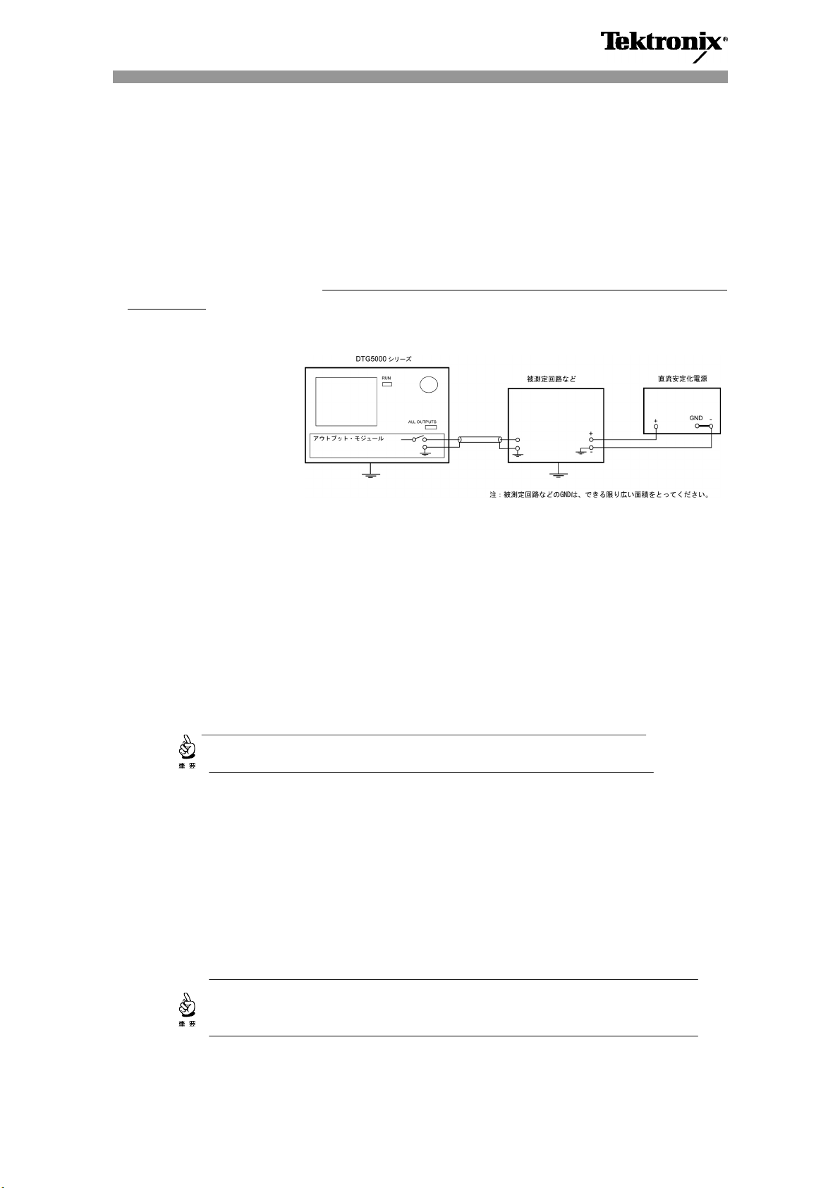
データ・タイミング・ゼネレータを被測定回路などに接続するときは、下図を参照の上、適切な接地を行
ってください。被測定回路などが適切に接地されていない場合、あるいは被測定回路の電源を投入(切
断)するタイミングが不適切でも、
損傷を与えることがあります。
データ・タイミング・ゼネレータ用の各アウトプット・モジュールの最大許容電流は次のとおりです。
・ DTGM10型 :±40 mA
・ DTGM20 型 :±80 mA
・ DTGM30 型 :±80 mA
データ・タイミング・ゼネレータに不用意な回路電流が流入するのを防止するため、被測定回路などの
電源投入(切断)するタイミングは、次の手順に従ってください。
① RUN ボタンを押して(またはコマンドを使用して)、データ・タイミング・ゼネレータを Stopped 状態に
します(内部のクロック・オシレータが停止します)。
② 次のいずれかの方法によりデータ・タイミング・ゼネレータにインストールされているアウトプット・モ
ジュールの出力リレーをオフにします。
• すべての出力リレーを同時にオフにする場合: ALL OUTPUTS ボタンを押す。
• 特定の出力リレーのみをオフにする場合: LEVEL ボタンを押す→出力リレーをオフにしたい
チャンネルの OUTPUT 欄にカーソルを移動→Off に設定
③ 被測定回路などの電源を投入(切断)します。
被測定回路などの電源 AC プラグの抜き差しも電源投入(切断)と同等です。
不用意な回路電流が発生してアウトプット・モジュールの出力回路に
■ 被測定回路との接続を変更するときの注意
被測定回路との接続を変更するときには、次の手順に従ってください。
1) 被測定回路の電源を切ります。切断手順は前項①~③までの手順に従ってください。次に被測
定回路との接続の変更や交換を行います。
2) 被測定回路の電源を投入した後、アウトプット・モジュールの出力リレーをオンにし、RUN ボタンを
押してデータ・タイミング・ゼネレータを Running 状態にします(内部のクロック・オシレータが作動し
ます)。
データ・タイミング・ゼネレータの詳しい操作方法については、DTG5000 ユーザ・マニュアルを参照してください。
被測定回路からの影響を避けるため、データ・タイミング・ゼネレータが Stopped
状態のときは、必ず出力リレーをオフにしておいてください。
061-4261-01
Page 2
Notice for Using the Data Timing Generator
Observe the following requirements for using the DTG5000 Series Data Timing Generators in a safe and
correct way.
Requirements for grounding, or powering on/off the Device Under Test
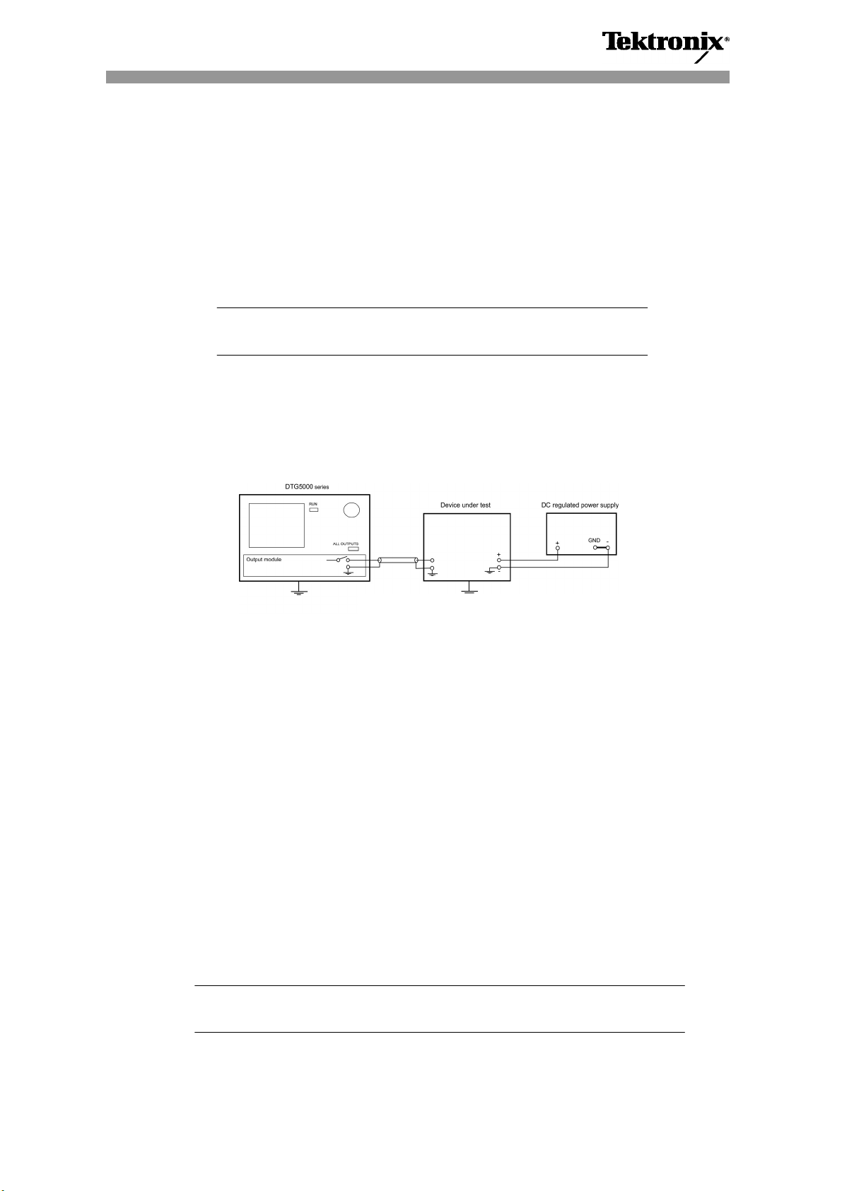
Pay attention when connecting the data timing generator to the DUT. Be sure the DUT is properly grounded.
Refer to the following figure for grounding information.
CAUTION:
The allowable maximum current of each data timing generator output module is as follows:
To protect the data timing generator from excessive current, perform the following procedure when you turn
on/off peripheral circuits:
1. With the RUN button (or a command), set the data timing generator to Stopped state (the internal clock
oscillator stops).
2. Turn the output relay(s) off on the output module(s) installed in the data timing generator:
When turning off all the outputs relays: push the ALL OUTPUTS button.
To turn the output relay(s) off, push the LEVEL button move the cursor to the output channel(s)
you want off set the channel(s) to Off
3. Turn on/off peripheral circuits.
Requirements for changing connections to the device under test
To protect the data timing generator from excessive current, perform the following procedure when you
change the connections to the DUT:
1. Turn off the power of peripheral circuits in accordance with above process from 1 to 3. And then,
replace/switch the DUT.
2. Turn on peripheral circuits, then set the output module output relay(s) to On. Then, set the data timing
generator to Running state with the RUN button. The internal clock oscillator is operating.
NOTE: To avoid adverse effects caused by the DUT, be sure to turn the data timing generator
output relay(s) off when it is the Stopped state.
For detailed information about using the data timing generator, refer to the DTG5000 User manual.
If the DUT is grounded incorrectly or powered on/off with inadequate timing,
damage to the output circuit may occur due to excessive current.
・ DTGM10 output module: ±40 mA
・ DTGM20 output module: ±80 mA
・ DTGM30 output module: ±80 mA
Note: Provide the device under test with GND area as large as possible.
061-4261-01
 Loading...