

Page 1
Installing the Output Module in
the DTG5000 series Data Timing Generator
The DTG5000 Series Data Timing Generator mainframe and output module(s) are shipped separately.
The DTGM10, DTGM20, DTGM21, DTGM30, DTGM31 and DTGM32 are output modules that can
be used with the DTG5000 mainframe. These modules can be used in any combination and in any slot.
There are functional differences between slot A though slot D and slot E though slot H. Refer to the
Mainframe and Output Configuration subsection in the DTG5000 User Manual. It is recommended
that you use slot A when only one output module is installed in the mainframe.
Electrostatic Discharge
To prevent electrostatic damage to the DTG5000 Series output modules, follow the precautions
described below.
CAUTION. Output modules are inherently vulnerable to a static damage.
Be sure to operate the output module in a static-controlled environment. If the
output module is not going to be in use for an extended period of time, attach
the connector caps and SMA termination (DTGM30, DTGM31, DTGM32) to
the output module. Store the output module in the antistatic bag. The
connector caps and SMA terminations (DTGM30, DTGM31, DTGM32) are
provided with your output module.
Installing an Output Module
To install the output module, first turn off the instrument using the front panel On/Standby switch.
CAUTION. To prevent damage to the output module or mainframe, never
install or remove an output module when the mainframe is powered on. Avoid
touching the board surface or connectors with your fingers when you handle
the module. Attach the blank panel to the slot(s) when the output module(s) are
not installed.
1. Verify that the data timing generator mainframe is not powered on.
2. Remove the blank panel from the mainframe slot.
3. Align the output module with the slot.
4. Gently push the output module into the slot using firm pressure.
5. Once the module is seated, tighten the two screws with either a flat head or a Philips
screwdriver to secure the module to the mainframe. To prevent damage to the module, use a
torque screwdriver and tighten the screw to the range of 25 to 35 N-cm ( 2.2 in lb to 3.1 in lb ).
071-1616-00
1
Page 2
Removing an Output Module
Verify that the data timing generator mainframe is not powered on.
1. To remove an output module from the mainframe, first turn off the instrument using the
On/Standby switch.
2. Loosen the two screws.
3. Grasp the right and left screws and slowly pull the module out of the the mainframe.
4. Attach a blank panel to the slot(s).
Signal output Connector Care
Never attach a cable to signal output connectors if the cable has a worn or damaged connector because
you may damage the output module connector. Use extra care when attaching or removing a cable
from the connectors. Turn only the nut, not the cable. When attaching a cable to an output module
connector, align the connectors carefully before turning the nut. Use light finger pressure to make this
initial connection. Then tighten the nut lightly with a wrench.
CAUTION. For best repeatability and to prolong the life of both connectors,
use a torque wrench and tighten the connection in the range of 79-112 N-cm
(7 in lb to 10 in lb ).
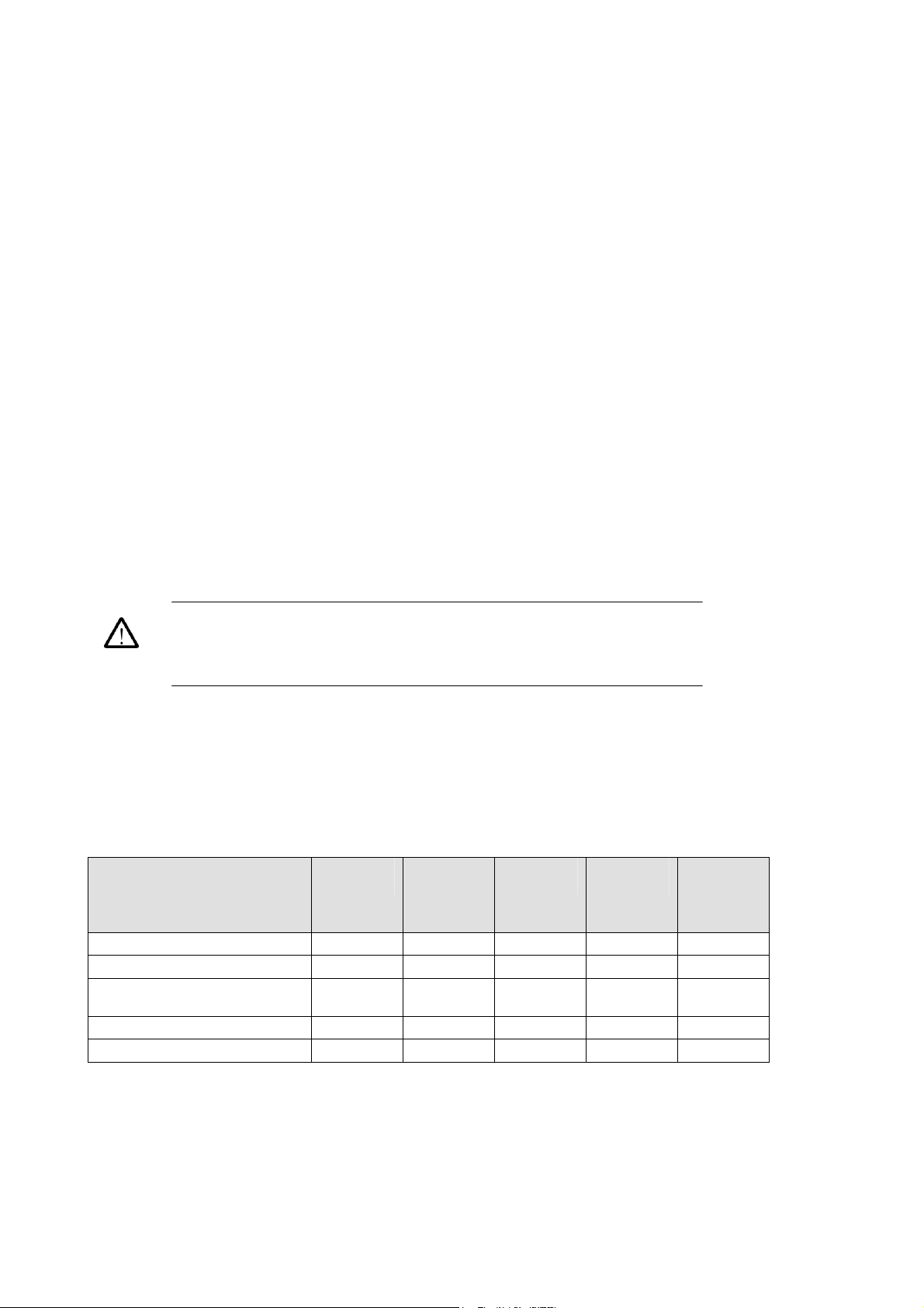
Contents list (accessories)
SMA Connector Cap
50Ω SMA Terminator
Microsoft Windows 2000
Recovery Disk
Application Software Disk
Documents Disk
*50Ω SMA Terminator part number: 015-1022-01
DTGM10 DTGM20
/DTGM21
4 4 2 2 3
none none 2* 1* 1*
0 0/1 0 1 1
0 0/1 0 1 1
1 1 1 1 1
DTGM30 DTGM31 DTGM32
2
Page 3
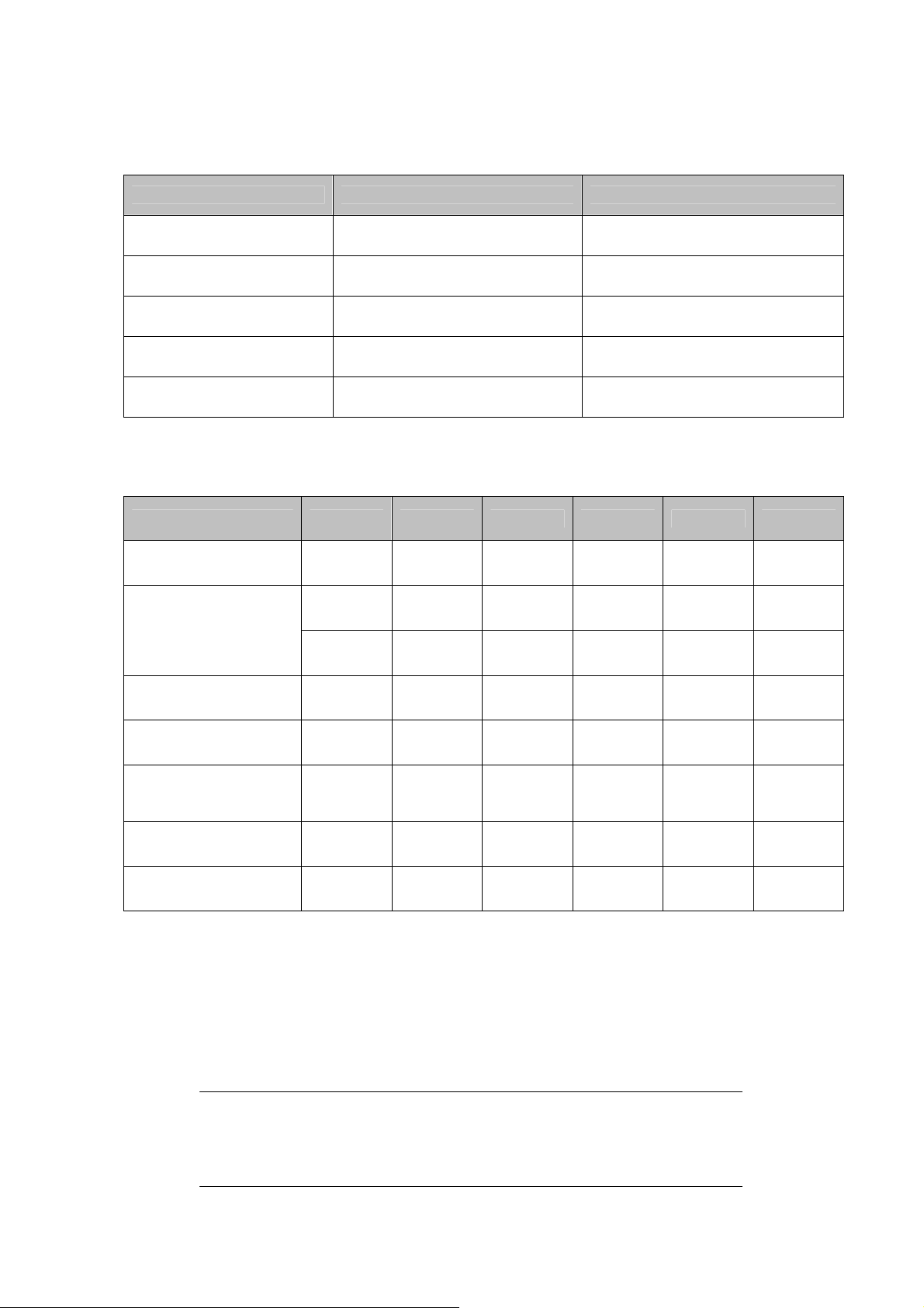
Specification
Mainframe DTG5078 DTG5274 / DTG5334
Maximum Data Rate
Number of card slot
Delay control
Width control
Master slave operation
750 Mb/s
A, B, C, D, E, F, G, H
Eight slots
1 ps resolution
(All channel)
5 ps resolution
(All channel in slot A to D)
Up to 3 boxes Up to 2 boxes
2.7 Gb/s (DTG5274)
3.35 Gb/s (DTG5334)
A, B, C, D
Four slots
0.2 ps resolution
(All channel)
5 ps resolution
(All channel)
Output Module DTGM10 DTGM20 DTGM21 DTGM30 DTGM31 DTGM32
Number of channel
Amplitude ( 50Ω)
(1MΩ)
*1
4 or 2
4 or 2*1
3.5 Vp-p*2 3.5 Vp-p*3
10 Vp-p 7 Vp-p 7.81 Vp-p
*1
2 1 1
4 or 2
5.35 Vp-p
3.90 Vp-p
*4
1.25 Vp-p 1.25 Vp-p 1.25 Vp-p
*5
*6
2.5 Vp-p 2.5 Vp-p 2.5 Vp-p
Source Impedance
(typical)
Maximum output
current
Rise /Fall Time
(20~80%) at 1Vp-p
into 50 Ω
Inhibit Input
External Jitter Input
50Ω 50Ω
+/- 40 mA +/- 80 mA +/- 80 mA +/- 80 mA +/- 80 mA +/- 80 mA
< 540 ps
(Variable)
< 340 ps
(Variable)
- - Yes - - -
- - - - Yes Yes
23Ω or
*7
50 Ω
< 350 ps < 110 ps < 110 ps < 110 ps
*1. Ch3 and Ch4 are not available in the DTG5274 or the DTG5334.
*2. This value is limited by Maximum Output (+/-40mA Max.)
*3. This value is limited by Maximum Output (+/-80mA Max.)
*4. Source impedance is 23Ω
*5. Source impedance is 50Ω
*6. Recommended source impedance is 50Ω
*7. This is selectable by moving the conductor in the box.
NOTE When the module( DTGM21, DTGM31 and DTGM32) is installed in
the DTG5078 or the DTG5274, applies to firmware version1.xx. You have to
upgrade the OS by using attached the Windows2000 Recovery Disk. Please refer
to Appendix B “System Recovery” in User Manual.
50Ω 50Ω 50Ω
3
Page 4

4
Page 5

DTG5000 シリーズ データ・タイミング・ゼネレータ用
アウトプット・モジュールの装着について
DTG5000 シリーズ メインフレーム(DTG5078 型、DTG5274 型、DTG5334 型)には、アウトプット・モジュ
ール DTGM10 型、DTGM20 型、DTGM21 型、DTGM30 型、DTGM31 型、DTGM32 型があり、別梱包で
出荷されます。メインフレームのスロットとアウトプット・モジュールの組み合わせは自由です。
ただし、DTG5078 型のスロット A-D と E-H では機能的な違いがあります(詳細は、ユーザ・マニュアル
「DTG5000 シリーズの比較」を参照)。スロット A から順に装着するのが標準的な使い方です。
機器の故障、損傷を防ぐため次の点をお守りください。
• アウトプット・モジュールの取り付け、取り外しは電源オフの状態で行なってください。
• アウトプット・モジュールを取り扱うときは、基板面、コネクタ部分は直接手で触れない
でください。
• 長期使用しない場合は、付属のコネクタ・キャップおよびターミネータ(DTGM30 型、
DTGM31 型、DTGM32 型に付属)をつけてください。
• 本体から取り外して保管する場合は、静電対策袋に入れて保管してください。
• アウトプット・モジュールを装着しないスロットは、ブランク・パネルを必ず付けてくださ
い。
取り付け手順
1. DTG5000 シリーズ本体の電源がオフであることを確認します。
2. 使用するスロットについているブランク・パネルを外します。
3. モジュールをスロットの溝に合わせます。
4. 丁寧にモジュールをコネクタにしっかり挿入されるまで押し込みます。
5. 左右の取り付けネジをプラス・ドライバまたはマイナス・ドライバで、しっかりと固定します。トル
ク・ドライバ工具を使用する場合には、25~35N・cmで締め過ぎないように注意してください。
取り外し手順
1. DTG5000 シリーズ本体の電源をオフにします。
2. 取り付けネジを緩めます。
3. 取り付け手順と逆の手順で取り外します。その際、取り付けネジを持ってモジュールを引き出
します
4. 未使用のスロットにはブランク・パネルを装着します。
5
Page 6

出力信号コネクタの取り扱い注意
出力信号コネクタの損傷を防止する為、接続コネクタが不良の SMA ケーブルを使用しないでください。コ
ネクタにケーブルを接続あるいは外す場合、ケーブルではなくナット部分を回すなど、その取り扱いに注
意してください。また、しっかり固定する場合などは、手である程度締めてから、レンチなどの工具を使用
して取り付けてください。
機器の故障、損傷を防ぐため次の点をお守りください。
トルク・レンチ工具を使用する場合は、コネクタを破損する恐れがありますので、
適用範囲 79~112N・cmで、締め過ぎないように注意してください。
■内容物リスト(付属品)
DTGM10 型 DTGM20 型 /
DTGM21 型
SMA コネクタ・キャップ
50Ω SMA ターミネータ
Microsoft
Windows 2000
リカバリ Disk
Application ソフトウェア
Disk
ドキュメント CD 1 1 1 1 1
* 50Ω SMA ターミネータ部品番号: 015-1022-01
4 4 2 2 3
無し 無し 2* 1
0 0/1 0 1 1
0 0/1 0 1 1
DTGM30 型 DTGM31 型 DTGM32 型
*
1
*
6
Page 7

■仕様
(詳細は DTG5000 シリーズ本体付属の Technical Reference Manual を参照してください。)
DTG5000 シリーズ本体 DTG5027 型 DTG5274 型/DTG5334 型
最大データレート
750 Mb/s
スロット枚数(モジュール挿入数) A,B,C,D,E,F,G,H
8スロット
Lead Delay 分解能 1p分解能
(全チャンネル)
パルス幅分解能 5 ps
(A,B,C,D スロットの全チャンネル)
マスター・スレーブ動作 3台まで (マスタ1,スレーブ2) 2台まで (マスタ1、スレーブ1)
モジュール DTGM10 型 DTGM20 型 DTGM21 型 DTGM30 型 DTGM31 型 DTGM32 型
有効チャンネル
数
出力振幅
50Ω入力
1MΩ入力
ソース
インピーダンス
(代表値)
4
*1
2
(CH1,CH2)
3.5 Vp-p
*2
4
*1
2
(CH1,CH2)
3.5 Vp-p
*3
4
*1
2
(CH1,CH2)
5.35 Vp-p
3.90 Vp-p
*4
*5
2 1
1.25 Vp-p 1.25 Vp-p 1.25 Vp-p
10 Vp-p 7 Vp-p 7.81 Vp-p*6 2.5Vp-p 2.5Vp-p 2.5 Vp-p
50Ω 50Ω
23Ωまたは
*7
50Ω
50Ω 50Ω 50Ω
最大出力電流 +/- 40 mA +/- 80 mA +/- 80 mA +/- 80 mA +/- 80 mA +/- 80 mA
立上り/立下り
時間
(20~80%,50Ω,
1Vp-p振幅)
540 ps
以下
(可変)
340 ps
以下
(可変)
350 ps
以下
110 ps
以下
インヒビット入力 - - ○ - - 外部ジッタ入力 - - - - ○ ○
* 1. DTG5274 型および DTG5334 型では、CH3とCH4は使用できません。
* 2. 最大+/-40mA の電流制限を受けます。
* 3. 最大+/-80mA の電流制限を受けます。
* 4. ソースインピーダンスは 23Ω
* 5. ソースインピーダンスは 50Ω
* 6. 推奨ソースインピーダンスは 50Ω
* 7. DTGM21 型機器内にあるコンダクタで選択
DTGM21 型、DTGM31 型および DTGM32 型を本体 DTG5078 型/DTG5274
型(ファームウェア Version 1.xx)に挿入して使用する場合には、OS を添付
Windows2000 リカバリ・ディスクでアップグレードする必要があります。詳細は、
ユーザ・マニュアルの付録「システムの復旧」をご参照ください。
2.7 Gb/s (DTG5274 型)
3.35 Gb/s (DTG5334 型)
A,B,C,D
4スロット
0.2 ps分解能
(全チャンネル)
5 ps
(全チャンネル)
1
110 ps
以下
110 ps
以下
7
Page 8

8
 Loading...