


Programmer Manual
DTG5000 Series
Data Timing Generators
071-1610-01
This document applies to program version 2.0.0 and above of
the DTG5000 Series.
www.tektronix.com

Copyright © Tektronix, Inc. All rights reserved. Licensed software products are owned by Tektronix or its subsidiaries
or suppliers, and are protected by national copyright laws and international treaty provisions.
Tektronix products are covered by U.S. and foreign patents, issued and pending. Information in this publication
supercedes that in all previously published material. Specifications and price change privileges reserved.
TEKTRONIX and TEK are registered trademarks of Tektronix, Inc.
Contacting Tektronix
Tektronix, Inc.
14200 SW Karl Braun Drive
P.O. Box 500
Beaverton, OR 97077
USA
For product information, sales, service, and technical support:
In North America, call 1-800-833-9200.
Worldwide, visit www.tektronix.com to find contacts in your area.

WARRANTY2
Tektronix warrants that this product will be free from defects in materials and workmanship for a period of one (1)
year from the date of shipment. If any such product proves defective during this warranty period, Tektronix, at its
option, either will repair the defective product without charge for parts and labor, or will provide a replacement in
exchange for the defective product. Parts, modules and replacement products used by Tektronix for warranty work may
be new or reconditioned to like new performance. All replaced parts, modules and products become the property of
Tektronix.
In order to obtain service under this warranty, Customer must notify Tektronix of the defect before the expiration of
the warranty period and make suitable arrangements for the performance of service. Customer shall be responsible for
packaging and shipping the defective product to the service center designated by Tektronix, with shipping charges
prepaid. Tektronix shall pay for the return of the product to Customer if the shipment is to a location within the country
in which the Tektronix service center is located. Customer shall be responsible for paying all shipping charges, duties,
taxes, and any other charges for products returned to any other locations.
This warranty shall not apply to any defect, failure or damage caused by improper use or improper or inadequate
maintenance and care. Tektronix shall not be obligated to furnish service under this warranty a) to repair damage
resulting from attempts by personnel other than Tektronix representatives to install, repair or service the product; b) to
repair damage resulting from improper use or connection to incompatible equipment; c) to repair any damage or
malfunction caused by the use of non-Tektronix supplies; or d) to service a product that has been modified or integrated
with other products when the effect of such modification or integration increases the time or difficulty of servicing the
product.
THIS WARRANTY IS GIVEN BY TEKTRONIX WITH RESPECT TO THE PRODUCT IN LIEU OF ANY
OTHER WARRANTIES, EXPRESS OR IMPLIED. TEKTRONIX AND ITS VENDORS DISCLAIM ANY
IMPLIED WARRANTIES OF MERCHANTABILITY OR FITNESS FOR A PARTICULAR PURPOSE.
TEKTRONIXÅf RESPONSIBILITY TO REPAIR OR REPLACE DEFECTIVE PRODUCTS IS THE SOLE
AND EXCLUSIVE REMEDY PROVIDED TO THE CUSTOMER FOR BREACH OF THIS WARRANTY.
TEKTRONIX AND ITS VENDORS WILL NOT BE LIABLE FOR ANY INDIRECT, SPECIAL,
INCIDENTAL, OR CONSEQUENTIAL DAMAGES IRRESPECTIVE OF WHETHER TEKTRONIX OR
THE VENDOR HAS ADVANCE NOTICE OF THE POSSIBILITY OF SUCH DAMAGES.


Table of Contents
Getting Started
Syntax and Commands
Preface . . . . . . . . . . . . . . . . . . . . . . . . . . . . . . . . . . . . . . . . . . . . . . . . . . . . . . . . . . . . . vii
Related Manuals. . . . . . . . . . . . . . . . . . . . . . . . . . . . . . . . . . . . . . . . . . . . . . . . . . . . . . . vii
Getting Started . . . . . . . . . . . . . . . . . . . . . . . . . . . . . . . . . . . . . . . . . . . . . . . . . . . . . 1-1
Manual Overview. . . . . . . . . . . . . . . . . . . . . . . . . . . . . . . . . . . . . . . . . . . . . . . . . . . . . 1-1
Setting Up Remote Communications Using GPIB . . . . . . . . . . . . . . . . . . . . . . . . . . . 1-3
Command Syntax . . . . . . . . . . . . . . . . . . . . . . . . . . . . . . . . . . . . . . . . . . . . . . . . . . . 2-1
SCPI Commands and Queries . . . . . . . . . . . . . . . . . . . . . . . . . . . . . . . . . . . . . . . . . . . 2-2
IEEE 488.2 Common Commands . . . . . . . . . . . . . . . . . . . . . . . . . . . . . . . . . . . . . . . 2-10
Specifying a Physical Channel. . . . . . . . . . . . . . . . . . . . . . . . . . . . . . . . . . . . . . . . . . 2-11
Syntax Diagrams . . . . . . . . . . . . . . . . . . . . . . . . . . . . . . . . . . . . . . . . . . . . . . . . . . . . 2-12
Command Groups . . . . . . . . . . . . . . . . . . . . . . . . . . . . . . . . . . . . . . . . . . . . . . . . . . 2-13
Functional Groups . . . . . . . . . . . . . . . . . . . . . . . . . . . . . . . . . . . . . . . . . . . . . . . . . . . 2-13
Command Quick Reference. . . . . . . . . . . . . . . . . . . . . . . . . . . . . . . . . . . . . . . . . . . . 2-14
Command Summaries . . . . . . . . . . . . . . . . . . . . . . . . . . . . . . . . . . . . . . . . . . . . . . . . 2-16
Command Descriptions . . . . . . . . . . . . . . . . . . . . . . . . . . . . . . . . . . . . . . . . . . . . . 2-21
BLOCk:DELete (No Query Form) . . . . . . . . . . . . . . . . . . . . . . . . . . . . . . . . . . . . . . 2-21
BLOCk:DELete:ALL (No Query Form) . . . . . . . . . . . . . . . . . . . . . . . . . . . . . . . . . . 2-21
BLOCk:LENGth (?). . . . . . . . . . . . . . . . . . . . . . . . . . . . . . . . . . . . . . . . . . . . . . . . . . 2-22
BLOCk:NEW (No Query Form) . . . . . . . . . . . . . . . . . . . . . . . . . . . . . . . . . . . . . . . . 2-22
BLOCk:SELect (?). . . . . . . . . . . . . . . . . . . . . . . . . . . . . . . . . . . . . . . . . . . . . . . . . . . 2-23
*CAL? (Query Only) . . . . . . . . . . . . . . . . . . . . . . . . . . . . . . . . . . . . . . . . . . . . . . . . . 2-23
CALibration[:ALL] (?) . . . . . . . . . . . . . . . . . . . . . . . . . . . . . . . . . . . . . . . . . . . . . . . 2-24
*CLS (No Query Form) . . . . . . . . . . . . . . . . . . . . . . . . . . . . . . . . . . . . . . . . . . . . . . . 2-25
DIAGnostic:DATA? (Query Only). . . . . . . . . . . . . . . . . . . . . . . . . . . . . . . . . . . . . . . 2-25
DIAGnostic:IMMediate (?) . . . . . . . . . . . . . . . . . . . . . . . . . . . . . . . . . . . . . . . . . . . . 2-26
DIAGnostic:SELect (?) . . . . . . . . . . . . . . . . . . . . . . . . . . . . . . . . . . . . . . . . . . . . . . . 2-27
*ESE (?) . . . . . . . . . . . . . . . . . . . . . . . . . . . . . . . . . . . . . . . . . . . . . . . . . . . . . . . . . . . 2-28
*ESR? (Query Only) . . . . . . . . . . . . . . . . . . . . . . . . . . . . . . . . . . . . . . . . . . . . . . . . . 2-28
GROup:DELete (No Query Form). . . . . . . . . . . . . . . . . . . . . . . . . . . . . . . . . . . . . . . 2-29
GROup:DELete:ALL (No Query Form) . . . . . . . . . . . . . . . . . . . . . . . . . . . . . . . . . . 2-29
GROup:NEW (No Query Form) . . . . . . . . . . . . . . . . . . . . . . . . . . . . . . . . . . . . . . . . 2-30
GROup:WIDTh (?) . . . . . . . . . . . . . . . . . . . . . . . . . . . . . . . . . . . . . . . . . . . . . . . . . . 2-30
*IDN? (Query Only) . . . . . . . . . . . . . . . . . . . . . . . . . . . . . . . . . . . . . . . . . . . . . . . . . 2-31
JGENeration:AMPLitude (?) . . . . . . . . . . . . . . . . . . . . . . . . . . . . . . . . . . . . . . . . . . . 2-31
JGENeration:AMPLitude:UNIT (?) . . . . . . . . . . . . . . . . . . . . . . . . . . . . . . . . . . . . . 2-32
JGENeration:EDGE (?) . . . . . . . . . . . . . . . . . . . . . . . . . . . . . . . . . . . . . . . . . . . . . . . 2-33
JGENeration:FREQuency (?). . . . . . . . . . . . . . . . . . . . . . . . . . . . . . . . . . . . . . . . . . . 2-34
JGENeration:GSOurce (?) . . . . . . . . . . . . . . . . . . . . . . . . . . . . . . . . . . . . . . . . . . . . . 2-34
JGENeration:MODE (?) . . . . . . . . . . . . . . . . . . . . . . . . . . . . . . . . . . . . . . . . . . . . . . 2-35
JGENeration:PROFile (?) . . . . . . . . . . . . . . . . . . . . . . . . . . . . . . . . . . . . . . . . . . . . . 2-36
DTG5000 Series Data Timing Generators Programmer Manual i

Table of Contents
JGENeration[:STATe] (?) . . . . . . . . . . . . . . . . . . . . . . . . . . . . . . . . . . . . . . . . . . . . . . 2-37
MMEMory:LOAD (No Query Form). . . . . . . . . . . . . . . . . . . . . . . . . . . . . . . . . . . . . 2-38
MMEMory:STORe (No Query Form) . . . . . . . . . . . . . . . . . . . . . . . . . . . . . . . . . . . . 2-38
*OPC (?) . . . . . . . . . . . . . . . . . . . . . . . . . . . . . . . . . . . . . . . . . . . . . . . . . . . . . . . . . . . 2-38
*OPT? (Query Only). . . . . . . . . . . . . . . . . . . . . . . . . . . . . . . . . . . . . . . . . . . . . . . . . . 2-39
OUTPut:CLOCk:AMPLitude (?) . . . . . . . . . . . . . . . . . . . . . . . . . . . . . . . . . . . . . . . . 2-40
OUTPut:CLOCk:OFFSet (?). . . . . . . . . . . . . . . . . . . . . . . . . . . . . . . . . . . . . . . . . . . . 2-40
OUTPut:CLOCk[:STATe] (?) . . . . . . . . . . . . . . . . . . . . . . . . . . . . . . . . . . . . . . . . . . . 2-41
OUTPut:CLOCk:TIMPedance(?) . . . . . . . . . . . . . . . . . . . . . . . . . . . . . . . . . . . . . . . . 2-41
OUTPut:CLOCk:TVOLtage(?). . . . . . . . . . . . . . . . . . . . . . . . . . . . . . . . . . . . . . . . . . 2-42
OUTPut:DC:HLIMit(?). . . . . . . . . . . . . . . . . . . . . . . . . . . . . . . . . . . . . . . . . . . . . . . . 2-42
OUTPut:DC:LEVel(?). . . . . . . . . . . . . . . . . . . . . . . . . . . . . . . . . . . . . . . . . . . . . . . . . 2-43
OUTPut:DC:LIMit(?) . . . . . . . . . . . . . . . . . . . . . . . . . . . . . . . . . . . . . . . . . . . . . . . . . 2-44
OUTPut:DC:LLIMit(?) . . . . . . . . . . . . . . . . . . . . . . . . . . . . . . . . . . . . . . . . . . . . . . . . 2-45
OUTPut:DC[:STATe] (?). . . . . . . . . . . . . . . . . . . . . . . . . . . . . . . . . . . . . . . . . . . . . . . 2-46
OUTPut:STATe:ALL (No Query Form) . . . . . . . . . . . . . . . . . . . . . . . . . . . . . . . . . . . 2-46
PGEN<x>[<m>]:CH<n>:AMODe (?) . . . . . . . . . . . . . . . . . . . . . . . . . . . . . . . . . . . . 2-47
PGEN<x>[<m>]:CH<n>:AMPLitude(?) . . . . . . . . . . . . . . . . . . . . . . . . . . . . . . . . . . 2-48
PGEN<x>[<m>]:CH<n>:BDATa(?). . . . . . . . . . . . . . . . . . . . . . . . . . . . . . . . . . . . . . 2-49
PGEN<x>[<m>]:CH<n>:CPOint(?). . . . . . . . . . . . . . . . . . . . . . . . . . . . . . . . . . . . . . 2-50
PGEN<x>[<m>]:CH<n>:DATA(?). . . . . . . . . . . . . . . . . . . . . . . . . . . . . . . . . . . . . . . 2-51
PGEN<x>[<m>]:CH<n>:DCYCle(?). . . . . . . . . . . . . . . . . . . . . . . . . . . . . . . . . . . . . 2-52
PGEN<x>[<m>]:CH<n>:DTOFfset(?). . . . . . . . . . . . . . . . . . . . . . . . . . . . . . . . . . . . 2-53
PGEN<x>[<m>]:CH<n>:DTOFfset:STATe(?) . . . . . . . . . . . . . . . . . . . . . . . . . . . . . . 2-54
PGEN<x>[<m>]:CH<n>:HIGH(?). . . . . . . . . . . . . . . . . . . . . . . . . . . . . . . . . . . . . . . 2-55
PGEN<x>[<m>]:CH<n>:HLIMit(?) . . . . . . . . . . . . . . . . . . . . . . . . . . . . . . . . . . . . . 2-56
PGEN<x>[<m>]:CH<n>:IMPedance? (Query Only). . . . . . . . . . . . . . . . . . . . . . . . . 2-57
PGEN<x>[<m>]:CH<n>:JRANge? . . . . . . . . . . . . . . . . . . . . . . . . . . . . . . . . . . . . . . 2-57
PGEN<x>[<m>]:CH<n>:LDELay(?). . . . . . . . . . . . . . . . . . . . . . . . . . . . . . . . . . . . . 2-58
PGEN<x>[<m>]:CH<n>:LHOLd(?) . . . . . . . . . . . . . . . . . . . . . . . . . . . . . . . . . . . . . 2-59
PGEN<x>[<m>]:CH<n>:LIMit(?) . . . . . . . . . . . . . . . . . . . . . . . . . . . . . . . . . . . . . . . 2-60
PGEN<x>[<m>]:CH<n>:LLIMit(?). . . . . . . . . . . . . . . . . . . . . . . . . . . . . . . . . . . . . . 2-61
PGEN<x>[<m>]:CH<n>:LOW(?) . . . . . . . . . . . . . . . . . . . . . . . . . . . . . . . . . . . . . . . 2-62
PGEN<x>[<m>]:CH<n>:OFFSet(?) . . . . . . . . . . . . . . . . . . . . . . . . . . . . . . . . . . . . . 2-63
PGEN<x>[<m>]:CH<n>:OUTPut(?) . . . . . . . . . . . . . . . . . . . . . . . . . . . . . . . . . . . . . 2-64
PGEN<x>[<m>]:CH<n>:PHASe(?). . . . . . . . . . . . . . . . . . . . . . . . . . . . . . . . . . . . . . 2-65
PGEN<x>[<m>]:CH<n>:POLarity(?) . . . . . . . . . . . . . . . . . . . . . . . . . . . . . . . . . . . . 2-66
PGEN<x>[<m>]:CH<n>:PRATe(?) . . . . . . . . . . . . . . . . . . . . . . . . . . . . . . . . . . . . . . 2-67
PGEN<x>[<m>]:CH<n>:SLEW(?) . . . . . . . . . . . . . . . . . . . . . . . . . . . . . . . . . . . . . . 2-68
PGEN<x>[<m>]:CH<n>:TDELay(?). . . . . . . . . . . . . . . . . . . . . . . . . . . . . . . . . . . . . 2-69
PGEN<x>[<m>]:CH<n>:THOLd(?) . . . . . . . . . . . . . . . . . . . . . . . . . . . . . . . . . . . . . 2-70
PGEN<x>[<m>]:CH<n>:TIMPedance(?) . . . . . . . . . . . . . . . . . . . . . . . . . . . . . . . . . 2-71
PGEN<x>[<m>]:CH<n>:TVOLtage(?) . . . . . . . . . . . . . . . . . . . . . . . . . . . . . . . . . . . 2-72
PGEN<x>[<m>]:CH<n>:TYPE(?). . . . . . . . . . . . . . . . . . . . . . . . . . . . . . . . . . . . . . . 2-73
PGEN<x>[<m>]:CH<n>:WIDTh(?) . . . . . . . . . . . . . . . . . . . . . . . . . . . . . . . . . . . . . 2-74
PGEN<x>[<m>]:ID? (Query Only) . . . . . . . . . . . . . . . . . . . . . . . . . . . . . . . . . . . . . . 2-75
*RST (No Query Form) . . . . . . . . . . . . . . . . . . . . . . . . . . . . . . . . . . . . . . . . . . . . . . . 2-75
SEQuence:DATA(?) . . . . . . . . . . . . . . . . . . . . . . . . . . . . . . . . . . . . . . . . . . . . . . . . . . 2-76
SEQuence:LENGth(?). . . . . . . . . . . . . . . . . . . . . . . . . . . . . . . . . . . . . . . . . . . . . . . . . 2-77
SIGNal:ASSign(?). . . . . . . . . . . . . . . . . . . . . . . . . . . . . . . . . . . . . . . . . . . . . . . . . . . . 2-78
SIGNal:<parameter>(?). . . . . . . . . . . . . . . . . . . . . . . . . . . . . . . . . . . . . . . . . . . . . . . . 2-79
ii DTG5000 Series Data Timing Generators Programmer Manual

Table of Contents
SIGNal:BDATa(?) . . . . . . . . . . . . . . . . . . . . . . . . . . . . . . . . . . . . . . . . . . . . . . . . . . . 2-80
SIGNal:DATA(?) . . . . . . . . . . . . . . . . . . . . . . . . . . . . . . . . . . . . . . . . . . . . . . . . . . . . 2-81
SIGNal:IMPedance? (Query Only) . . . . . . . . . . . . . . . . . . . . . . . . . . . . . . . . . . . . . . 2-82
SIGNal:JRANge(?) . . . . . . . . . . . . . . . . . . . . . . . . . . . . . . . . . . . . . . . . . . . . . . . . . . 2-82
*SRE (?). . . . . . . . . . . . . . . . . . . . . . . . . . . . . . . . . . . . . . . . . . . . . . . . . . . . . . . . . . . 2-83
*STB? (Query Only) . . . . . . . . . . . . . . . . . . . . . . . . . . . . . . . . . . . . . . . . . . . . . . . . . 2-84
SUBSequence:DATA(?). . . . . . . . . . . . . . . . . . . . . . . . . . . . . . . . . . . . . . . . . . . . . . . 2-84
SUBSequence:DELete (No Query Form) . . . . . . . . . . . . . . . . . . . . . . . . . . . . . . . . . 2-85
SUBSequence:DELete:ALL (No Query Form). . . . . . . . . . . . . . . . . . . . . . . . . . . . . 2-85
SUBSequence:LENGth(?) . . . . . . . . . . . . . . . . . . . . . . . . . . . . . . . . . . . . . . . . . . . . . 2-86
SUBSequence:NEW (No Query Form) . . . . . . . . . . . . . . . . . . . . . . . . . . . . . . . . . . . 2-86
SUBSequence:SELect(?) . . . . . . . . . . . . . . . . . . . . . . . . . . . . . . . . . . . . . . . . . . . . . . 2-87
SYSTem:ERRor[:NEXT]? (Query Only) . . . . . . . . . . . . . . . . . . . . . . . . . . . . . . . . . 2-87
SYSTem:KLOCk (?) . . . . . . . . . . . . . . . . . . . . . . . . . . . . . . . . . . . . . . . . . . . . . . . . . 2-88
SYSTem:VERSion? (Query Only) . . . . . . . . . . . . . . . . . . . . . . . . . . . . . . . . . . . . . . 2-89
TBAS:COUNt(?) . . . . . . . . . . . . . . . . . . . . . . . . . . . . . . . . . . . . . . . . . . . . . . . . . . . . 2-89
TBAS:CRANge(?). . . . . . . . . . . . . . . . . . . . . . . . . . . . . . . . . . . . . . . . . . . . . . . . . . . 2-90
TBAS:DOFFset(?) . . . . . . . . . . . . . . . . . . . . . . . . . . . . . . . . . . . . . . . . . . . . . . . . . . . 2-91
TBAS:EIN:IMMediate (No Query Form) . . . . . . . . . . . . . . . . . . . . . . . . . . . . . . . . . 2-91
TBAS:EIN:IMPedance(?) . . . . . . . . . . . . . . . . . . . . . . . . . . . . . . . . . . . . . . . . . . . . . 2-92
TBAS:EIN:LEVel(?) . . . . . . . . . . . . . . . . . . . . . . . . . . . . . . . . . . . . . . . . . . . . . . . . . 2-92
TBAS:EIN:POLarity(?) . . . . . . . . . . . . . . . . . . . . . . . . . . . . . . . . . . . . . . . . . . . . . . . 2-93
TBAS:FREQuency(?) . . . . . . . . . . . . . . . . . . . . . . . . . . . . . . . . . . . . . . . . . . . . . . . . 2-93
TBAS:JMODe(?) . . . . . . . . . . . . . . . . . . . . . . . . . . . . . . . . . . . . . . . . . . . . . . . . . . . . 2-94
TBAS:JTIMing(?) . . . . . . . . . . . . . . . . . . . . . . . . . . . . . . . . . . . . . . . . . . . . . . . . . . . 2-95
TBAS:JUMP (No Query Form). . . . . . . . . . . . . . . . . . . . . . . . . . . . . . . . . . . . . . . . . 2-95
TBAS:LDELay (?). . . . . . . . . . . . . . . . . . . . . . . . . . . . . . . . . . . . . . . . . . . . . . . . . . . 2-96
TBAS:MODE(?) . . . . . . . . . . . . . . . . . . . . . . . . . . . . . . . . . . . . . . . . . . . . . . . . . . . . 2-96
TBAS:OMODe(?) . . . . . . . . . . . . . . . . . . . . . . . . . . . . . . . . . . . . . . . . . . . . . . . . . . . 2-97
TBAS:PERiod(?) . . . . . . . . . . . . . . . . . . . . . . . . . . . . . . . . . . . . . . . . . . . . . . . . . . . . 2-98
TBAS:PRATe? (Query Only). . . . . . . . . . . . . . . . . . . . . . . . . . . . . . . . . . . . . . . . . . . 2-98
TBAS:RSTate? (Query Only) . . . . . . . . . . . . . . . . . . . . . . . . . . . . . . . . . . . . . . . . . . 2-99
TBAS:RUN (?). . . . . . . . . . . . . . . . . . . . . . . . . . . . . . . . . . . . . . . . . . . . . . . . . . . . . 2-100
TBAS:SMODe(?). . . . . . . . . . . . . . . . . . . . . . . . . . . . . . . . . . . . . . . . . . . . . . . . . . . 2-100
TBAS:SOURce(?) . . . . . . . . . . . . . . . . . . . . . . . . . . . . . . . . . . . . . . . . . . . . . . . . . . 2-101
TBAS:TIN:IMPedance(?) . . . . . . . . . . . . . . . . . . . . . . . . . . . . . . . . . . . . . . . . . . . . 2-102
TBAS:TIN:LEVel(?) . . . . . . . . . . . . . . . . . . . . . . . . . . . . . . . . . . . . . . . . . . . . . . . . 2-102
TBAS:TIN:SLOPe(?). . . . . . . . . . . . . . . . . . . . . . . . . . . . . . . . . . . . . . . . . . . . . . . . 2-103
TBAS:TIN:SOURce(?) . . . . . . . . . . . . . . . . . . . . . . . . . . . . . . . . . . . . . . . . . . . . . . 2-103
TBAS:TIN:TIMer(?) . . . . . . . . . . . . . . . . . . . . . . . . . . . . . . . . . . . . . . . . . . . . . . . . 2-104
TBAS:TIN:TRIGger (No Query Form). . . . . . . . . . . . . . . . . . . . . . . . . . . . . . . . . . 2-104
TBAS:VRATe? (Query Only) . . . . . . . . . . . . . . . . . . . . . . . . . . . . . . . . . . . . . . . . . 2-105
*TRG (No Query Form) . . . . . . . . . . . . . . . . . . . . . . . . . . . . . . . . . . . . . . . . . . . . . 2-105
*TST? (Query Only) . . . . . . . . . . . . . . . . . . . . . . . . . . . . . . . . . . . . . . . . . . . . . . . . 2-106
VECTor:BDATa(?). . . . . . . . . . . . . . . . . . . . . . . . . . . . . . . . . . . . . . . . . . . . . . . . . . 2-106
VECTor:BIOFormat(?) . . . . . . . . . . . . . . . . . . . . . . . . . . . . . . . . . . . . . . . . . . . . . . 2-109
VECTor:DATA(?). . . . . . . . . . . . . . . . . . . . . . . . . . . . . . . . . . . . . . . . . . . . . . . . . . . 2-110
VECTor:IMPort (No Query Form) . . . . . . . . . . . . . . . . . . . . . . . . . . . . . . . . . . . . . 2-112
VECTor:IMPort:AWG (No Query Form) . . . . . . . . . . . . . . . . . . . . . . . . . . . . . . . . 2-112
VECTor:IOFormat(?). . . . . . . . . . . . . . . . . . . . . . . . . . . . . . . . . . . . . . . . . . . . . . . . 2-113
*WAI (No Query Form) . . . . . . . . . . . . . . . . . . . . . . . . . . . . . . . . . . . . . . . . . . . . . . 2-115
DTG5000 Series Data Timing Generators Programmer Manual iii

Table of Contents
Status and Events
Status and Event Reporting . . . . . . . . . . . . . . . . . . . . . . . . . . . . . . . . . . . . . . . . . . . 3-1
Status Reporting Structure . . . . . . . . . . . . . . . . . . . . . . . . . . . . . . . . . . . . . . . . . . . . . . 3-1
Registers . . . . . . . . . . . . . . . . . . . . . . . . . . . . . . . . . . . . . . . . . . . . . . . . . . . . . . . . . . . .3-3
Status Registers . . . . . . . . . . . . . . . . . . . . . . . . . . . . . . . . . . . . . . . . . . . . . . . . . . . . . . . 3-3
Enable Registers . . . . . . . . . . . . . . . . . . . . . . . . . . . . . . . . . . . . . . . . . . . . . . . . . . . . . . 3-6
Queues. . . . . . . . . . . . . . . . . . . . . . . . . . . . . . . . . . . . . . . . . . . . . . . . . . . . . . . . . . . . . .3-7
Status and Event Processing Sequence . . . . . . . . . . . . . . . . . . . . . . . . . . . . . . . . . . . . . 3-8
Synchronizing Execution . . . . . . . . . . . . . . . . . . . . . . . . . . . . . . . . . . . . . . . . . . . . . . . 3-9
Messages . . . . . . . . . . . . . . . . . . . . . . . . . . . . . . . . . . . . . . . . . . . . . . . . . . . . . . . . . . . . 3-9
Messages and Codes . . . . . . . . . . . . . . . . . . . . . . . . . . . . . . . . . . . . . . . . . . . . . . . . . 3-11
Command Errors . . . . . . . . . . . . . . . . . . . . . . . . . . . . . . . . . . . . . . . . . . . . . . . . . . . . . 3-12
Execution Errors . . . . . . . . . . . . . . . . . . . . . . . . . . . . . . . . . . . . . . . . . . . . . . . . . . . . . 3-14
Device Specific Errors. . . . . . . . . . . . . . . . . . . . . . . . . . . . . . . . . . . . . . . . . . . . . . . . . 3-16
Query Errors . . . . . . . . . . . . . . . . . . . . . . . . . . . . . . . . . . . . . . . . . . . . . . . . . . . . . . . . 3-17
Power–On Events . . . . . . . . . . . . . . . . . . . . . . . . . . . . . . . . . . . . . . . . . . . . . . . . . . . . 3-17
User Request Events . . . . . . . . . . . . . . . . . . . . . . . . . . . . . . . . . . . . . . . . . . . . . . . . . . 3-17
Request Control Events. . . . . . . . . . . . . . . . . . . . . . . . . . . . . . . . . . . . . . . . . . . . . . . . 3-18
Operation Complete Events . . . . . . . . . . . . . . . . . . . . . . . . . . . . . . . . . . . . . . . . . . . . 3-18
Examples
Appendices
Glossary and Index
Programming Examples . . . . . . . . . . . . . . . . . . . . . . . . . . . . . . . . . . . . . . . . . . . . . . 4-1
Sample program . . . . . . . . . . . . . . . . . . . . . . . . . . . . . . . . . . . . . . . . . . . . . . . . . . . . . . 4-1
Appendix A: Character Charts . . . . . . . . . . . . . . . . . . . . . . . . . . . . . . . . . . . . . . . . A-1
Appendix B: GPIB Interface Specification . . . . . . . . . . . . . . . . . . . . . . . . . . . . . . B-1
Interface Functions . . . . . . . . . . . . . . . . . . . . . . . . . . . . . . . . . . . . . . . . . . . . . . . . . . . B-1
Interface Messages . . . . . . . . . . . . . . . . . . . . . . . . . . . . . . . . . . . . . . . . . . . . . . . . . . . B-3
Appendix C: Factory Initialization Settings . . . . . . . . . . . . . . . . . . . . . . . . . . . . . C-1
Appendix D: File Format . . . . . . . . . . . . . . . . . . . . . . . . . . . . . . . . . . . . . . . . . . . . . D-1
File Format and Record Format . . . . . . . . . . . . . . . . . . . . . . . . . . . . . . . . . . . . . . . . . D-1
Record ID . . . . . . . . . . . . . . . . . . . . . . . . . . . . . . . . . . . . . . . . . . . . . . . . . . . . . . . . . . D-3
Loading a File . . . . . . . . . . . . . . . . . . . . . . . . . . . . . . . . . . . . . . . . . . . . . . . . . . . . . . D-16
Assigning a Channel . . . . . . . . . . . . . . . . . . . . . . . . . . . . . . . . . . . . . . . . . . . . . . . . . D-16
iv DTG5000 Series Data Timing Generators Programmer Manual

List of Figures
Table of Contents
Figure 1-1: Common message elements . . . . . . . . . . . . . . . . . . . . . . . . . . . . . . . . . 1-1
Figure 1-2: Basic operation of status and events reporting . . . . . . . . . . . . . . . . . 1-2
Figure 1-3: GPIB connector location . . . . . . . . . . . . . . . . . . . . . . . . . . . . . . . . . . . 1-3
Figure 1-4: Typical GPIB network configurations . . . . . . . . . . . . . . . . . . . . . . . . 1-4
Figure 2-1: Example of SCPI subsystem hierarchy tree . . . . . . . . . . . . . . . . . . . . 2-2
Figure 2-2: Example of abbreviating a command . . . . . . . . . . . . . . . . . . . . . . . . . 2-5
Figure 2-3: Example of chaining commands and queries . . . . . . . . . . . . . . . . . . . 2-6
Figure 2-4: Example of omitting upper and lower-level nodes in a chained
message . . . . . . . . . . . . . . . . . . . . . . . . . . . . . . . . . . . . . . . . . . . . . . . . . 2-6
Figure 2-5: Typical syntax diagrams . . . . . . . . . . . . . . . . . . . . . . . . . . . . . . . . . . . 2-12
Figure 3-1: Error and Event handling process overview . . . . . . . . . . . . . . . . . . . 3-2
Figure 3-2: The Status Byte Register (SBR) . . . . . . . . . . . . . . . . . . . . . . . . . . . . . . 3-4
Figure 3-3: The Standard Event Status Register (SESR) . . . . . . . . . . . . . . . . . . . 3-5
Figure 3-4: The Event Status Enable Register (ESER) . . . . . . . . . . . . . . . . . . . . . 3-6
Figure 3-5: The Service Request Enable Register (SRER) . . . . . . . . . . . . . . . . . . 3-7
Figure 3-6: Status and Event processing sequence - Standard/Event status
block . . . . . . . . . . . . . . . . . . . . . . . . . . . . . . . . . . . . . . . . . . . . . . . . . . 3-8
Figure D-1: Record format . . . . . . . . . . . . . . . . . . . . . . . . . . . . . . . . . . . . . . . . . . . . D-1
Figure D-2: Record ID tree structure . . . . . . . . . . . . . . . . . . . . . . . . . . . . . . . . . . . D-2
DTG5000 Series Data Timing Generators Programmer Manual v

Table of Contents
List of Tables
Table 2-1: BNF symbols and meanings . . . . . . . . . . . . . . . . . . . . . . . . . . . . . . . . . . 2-1
Table 2-2: Query response examples . . . . . . . . . . . . . . . . . . . . . . . . . . . . . . . . . . . . 2-3
Table 2-3: Parameter types used in syntax descriptions . . . . . . . . . . . . . . . . . . . . 2-4
Table 2-4: Functional groups in the DTG command set . . . . . . . . . . . . . . . . . . . 2-13
Table 2-5: Common Commands . . . . . . . . . . . . . . . . . . . . . . . . . . . . . . . . . . . . . . . 2-16
Table 2-6: Device Commands . . . . . . . . . . . . . . . . . . . . . . . . . . . . . . . . . . . . . . . . . 2-17
Table 2-7: Self–test routines . . . . . . . . . . . . . . . . . . . . . . . . . . . . . . . . . . . . . . . . . . 2-27
Table 3-1: SBR bit functions . . . . . . . . . . . . . . . . . . . . . . . . . . . . . . . . . . . . . . . . . . . 3-4
Table 3-2: SESR bit functions . . . . . . . . . . . . . . . . . . . . . . . . . . . . . . . . . . . . . . . . . . 3-5
Table 3-3: Definition of event codes . . . . . . . . . . . . . . . . . . . . . . . . . . . . . . . . . . . . 3-11
Table 3-4: Command errors . . . . . . . . . . . . . . . . . . . . . . . . . . . . . . . . . . . . . . . . . . 3-12
Table 3-5: Execution errors . . . . . . . . . . . . . . . . . . . . . . . . . . . . . . . . . . . . . . . . . . . 3-14
Table 3-6: Device specific errors . . . . . . . . . . . . . . . . . . . . . . . . . . . . . . . . . . . . . . . 3-16
Table 3-7: Query errors . . . . . . . . . . . . . . . . . . . . . . . . . . . . . . . . . . . . . . . . . . . . . . 3-17
Table 3-8: Power–on events . . . . . . . . . . . . . . . . . . . . . . . . . . . . . . . . . . . . . . . . . . . 3-17
Table 3-9: User request events . . . . . . . . . . . . . . . . . . . . . . . . . . . . . . . . . . . . . . . . 3-17
Table 3-10: Request control events . . . . . . . . . . . . . . . . . . . . . . . . . . . . . . . . . . . . . 3-18
Table 3-11: Operation complete events . . . . . . . . . . . . . . . . . . . . . . . . . . . . . . . . . 3-18
Table A-1: The DTG character set . . . . . . . . . . . . . . . . . . . . . . . . . . . . . . . . . . . . . A-1
Table A-2: ASCII & GPIB code chart . . . . . . . . . . . . . . . . . . . . . . . . . . . . . . . . . . A-2
Table B-1: GPIB interface function implementation . . . . . . . . . . . . . . . . . . . . . . B-1
Table B-2: DTG standard interface message . . . . . . . . . . . . . . . . . . . . . . . . . . . . . B-3
Table C-1: Factory initialization settings . . . . . . . . . . . . . . . . . . . . . . . . . . . . . . . . C-1
Table D-1: Record ID used as an interior node . . . . . . . . . . . . . . . . . . . . . . . . . . D-3
Table D-2: Record ID-Root . . . . . . . . . . . . . . . . . . . . . . . . . . . . . . . . . . . . . . . . . . D-3
Table D-3: Record ID-Group . . . . . . . . . . . . . . . . . . . . . . . . . . . . . . . . . . . . . . . . . D-7
Table D-4: Record ID-Logical Channel . . . . . . . . . . . . . . . . . . . . . . . . . . . . . . . . D-7
Table D-5: Record ID-Block . . . . . . . . . . . . . . . . . . . . . . . . . . . . . . . . . . . . . . . . . . D-9
Table D-6: Record ID-Sub Sequence . . . . . . . . . . . . . . . . . . . . . . . . . . . . . . . . . . . D-9
Table D-7: Record ID-Sub Sequence Step . . . . . . . . . . . . . . . . . . . . . . . . . . . . . . . D-9
Table D-8: Record ID-Main Sequence . . . . . . . . . . . . . . . . . . . . . . . . . . . . . . . . . . D-9
Table D-9: Record ID-Pattern . . . . . . . . . . . . . . . . . . . . . . . . . . . . . . . . . . . . . . . D-10
Table D-10: Record ID-View . . . . . . . . . . . . . . . . . . . . . . . . . . . . . . . . . . . . . . . . . D-10
vi DTG5000 Series Data Timing Generators Programmer Manual

Preface
This is the programmer manual for the DTG5000 Series Data Timing Generators.
This manual provides information necessary for operating the instrument over the
General Purpose Interface Bus (GPIB) interface.
This manual provides the following information:
The Getting Started section describes how to connect and set up the data timing
generator for remote operation.
The Syntax and Commands section defines the command syntax and
processing conventions and describes each command in the data timing
generator command set.
The Status and Events section explains the status information and event
messages reported by the data timing generator.
The Programming Examples section describes how to use the Sample Program
of the data timing generator.
The Appendices section contains various tables of reference information.
Related Manuals
The Glossary and Index section contains a glossary of common terms and an
index to this manual.
Other documentation for the data timing generator includes:
The DTG5000 Series User Manual 2 (071-1609-xx) describes the operation of
the instrument.
DTG5000 Series Data Timing Generators Programmer Manual vii

Preface
viii DTG5000 Series Data Timing Generators Programmer Manual

Getting Started


Getting Started
Manual Overview
The DTG5000 Series Data Timing Generator has GPIB interface capability. You
can write computer programs that remotely set the front panel controls.
To help you get started with programming the data timing generator, this section
includes the following subsections:
Manual Overview - summarizes the type of programming information
contained in each major section in this manual.
Setting Up Remote Communications Using GPIB - describes how to connect
the data timing generator to a controller through the GPIB interface.
A summary of the information provided in each major section of this manual
follows:
Syntax and Commands
The Command Syntax subsection, which begins on page 2-1, describes the
structure and content of the messages your program sends to the data timing
generator. You can use the Standard Commands for Programmable Instruments
(SCPI) and IEEE 488.2 Common Commands. Figure 1-1 is an example of the
syntax and command parts diagrams used in the Command Syntax subsection.
Command parts
Header
FUNCtion:USER
Mnemonics
Syntax diagram
FUNCtion
Figure 1-1: Common message elements
:
USER
Comma
“FILE1”,“FLOPpy”
Space
Arguments
<file_name><space> <msus>
,
DTG5000 Series Data Timing Generators Programmer Manual 1-1

Getting Started
The Command Syntax subsection also describes the result of each command, and
provides examples of how you might use it. The Command Groups subsection,
which begins on page 2-13, provides a command list by functional area. The
Command Descriptions subsection, which begins on page 2-21, arranges
commands alphabetically.
Status and Events
Reporting
The program may request information from the data timing generator. The data
timing generator provides information in the form of status and error messages.
Figure 1-2 illustrates the basic operation of this system.
The Status and Events Reporting subsection, which begins on page 3-1, describes
how to use the status reporting functions that conform to SCPI and IEEE-488.2 in
your programs.
Your program requests
status and event reports.
Controller
DTGs ends status and event reports.
DTG (rear panel )
GPIB cable
Figure 1-2: Basic operation of status and events reporting
Programming Examples
The Programming Examples section, which begins on page 4-1, provides a sample
data timing generator program.
1-2 DTG5000 Series Data Timing Generators Programmer Manual

Setting Up Remote Communications Using GPIB
For remote operations, the instrument must be connected to the controller.
The data timing generator has a 24-pin GPIB connector on its rear panel, as shown
in Figure 1-3. This connector has a D-type shell and conforms to IEEE Std
488.2-1992.
Attach an IEEE Std 488.2-1992 GPIB cable (Tektronix part number 012-0991-xx)
to the GPIB connector.
Getting Started
GPIB connector
Figure 1-3: GPIB connector location
DTG5000 Series Data Timing Generators Programmer Manual 1-3

Getting Started
GPIB Requirements
Follow these rules when you use your data timing generator with a GPIB network:
Assign a unique device address to each device on the bus. Two devices can not
share the same device address.
Do not connect more than 15 devices to one bus.
Connect one device for every 2 meters (6 feet) of cable used.
Do not use more than 20 meters (65 feet) of cable to connect devices to a bus.
While using the network, turn on at least two-thirds of the devices on the
network.
Connect the devices on the network in a star or linear configuration, as shown
in Figure 1-4. Do not use loop or parallel configurations.
GPIBDevice
GPIBDeviceGPIBDevice
GPIBDevice
GPIBDevice
GPIBDevice
Figure 1-4: Typical GPIB network configurations
GPIBDevice
1-4 DTG5000 Series Data Timing Generators Programmer Manual

Syntax and Commands


Command Syntax
This section contains general information about command structure and syntax
usage. You should familiarize yourself with this material before using the data
timing generator command descriptions.
This manual describes commands and queries using Backus–Naur Form (BNF)
notation. Table 2-1 defines standard BNF symbols.
Table 2-1: BNF symbols and meanings
Symbol Meaning
<> Defined element
::= Is defined as
| Exclusive OR
{} Group; one element is required
[] Optional; can be omitted
. . . Previous element(s) may be repeated
() Comment
DTG5000 Series Data Timing Generators Programmer Manual 2-1

Command Syntax
SCPI Commands and Queries
The data timing generator uses a command language based on the SCPI standard.
The SCPI (Standard Commands for Programmable Instruments) standard was
created by a consortium to provide guidelines for remote programming of
instruments. These guidelines provide a consistent programming environment for
instrument control and data transfer. This environment uses defined programming
messages, instrument responses and data formats that operate across all SCPI
instruments, regardless of manufacturer.
The SCPI language is based on a hierarchical or tree structure that represents a
subsystem (see Figure 2-1). The top level of the tree is the root node; it is followed
by one or more lower–level nodes.
OUTPut
CLOCk
OFFSet
STATeAMPLitude
Root node
Lower-level
nodes
Figure 2-1: Example of SCPI subsystem hierarchy tree
You can create commands and queries from these subsystem hierarchy trees.
Commands specify actions for the instrument to perform. Queries return
measurement data and information about parameter settings.
2-2 DTG5000 Series Data Timing Generators Programmer Manual

Command Syntax
Creating Commands
Creating Queries
Query Responses
SCPI commands are created by stringing together the nodes of a subsystem
hierarchy and separating each node by a colon.
In Figure 2-1 on page 2-2, OUTPut is the root node and CLOCk, AMPLitude,
OFFSet, and STATe are lower–level nodes. To create an SCPI command, start
with the root node OUTPut and move down the tree structure adding nodes until
you reach the end of a branch. Most commands and some queries have parameters;
you must include a value for these parameters. The command descriptions, which
begin on page 2-21, list the valid values for all parameters.
For example, OUTPut:CLOCk:AMPLitude 2.0 is a valid SCPI command
created from the hierarchy tree in Figure 2-1 on page 2-2.
To create a query, start at the root node of a tree structure, move down to the end
of a branch, and add a question mark. OUTPut:CLOCk:AMPLitude? is an
example of a valid SCPI query using the hierarchy tree in Figure 2-1 on
page 2-2.
The query causes the data timing generator to return information about its status or
settings. When a query is sent to the data timing generator, only the values are
returned. When the returned value is a mnemonic, it is noted in abbreviated format,
as shown in Table 2-2.
Table 2-2: Query response examples
Query Response
SYSTem:VERSion? 1999.0
DIAGnostic:SELect? ALL
A few queries also initiate an operation action before returning information. For
example, the *CAL? query runs a calibration.
DTG5000 Series Data Timing Generators Programmer Manual 2-3

Command Syntax
Parameter Types
Parameters are indicated by angle brackets, such as <file_name>. There are several
different types of parameters, as listed in Table 2-3. The parameter type is listed
after the parameter. Some parameter types are defined specifically for the
DTG5000 series command set and some are defined by SCPI.
Table 2-3: Parameter types used in syntax descriptions
Parameter type Description Example
arbitrary block A block of data bytes #512234xxxxx...
where 5 indicates that the following 5
digits (12234) specify the length of
the data in bytes;
xxxxx... indicates the data
or
#0xxxxx...<LF><&EOI>
boolean Boolean numbers or NRf ON or ≠ 0
OFF or 0
discrete A list of specific values MIN, MAX
binary Binary numbers #B0110
octal Octal numbers #Q75, #Q3
hexadecimal
NR1
NR2
NR3
NRf
Numeric numeric Flexible decimal number that may be
string Alphanumeric characters (must be
numeric Integers 0, 1, 15, -1
numeric Decimal numbers 1.2, 3.141516, -6.5
numeric Floating point numbers 3.1415E-9, -16.1E5
numeric Flexible decimal number that may be
Hexadecimal numbers (0-9, A- F) #HAA, #H1
See NR1, NR2, NR3 examples in this
type NR1, NR2, or NR3
type NR1, NR2, NR3, or specific
value (MIN, MAX).
within quotation marks)
table
See NR1, NR2, NR3 discrete
examples in this table
“Testing 1, 2, 3”
About MIN, MAX
You can use MINimum, MAXimum keywords in addition to Numeric in the
commands with
“Numeric” parameter. You can set the minimum value or the
maximum value by the use of this keywords. You can query the minimum value or
the maximum value at that time.
2-4 DTG5000 Series Data Timing Generators Programmer Manual

Command Syntax
Special Characters
Abbreviating Commands,
Queries, and Parameters
The Line Feed (LF) character or the New Line (NL) character (ASCII 10), and all
characters in the range of ASCII 127-255 are defined as special characters. These
characters are used in arbitrary block arguments only; using these characters in
other parts of any command yields unpredictable results.
You can abbreviate most SCPI commands, queries, and parameters to an accepted
short form. This manual shows these commands as a combination of upper and
lower case letters. The upper case letters indicate the accepted short form of a
command, as shown in Figure 2-2. The accepted short form and the long form are
equivalent and request the same action of the instrument.
Long form of a
command
Accepted short form
of a command
OUTP
ut:CLOCk:AMPLitude 2.0
Minimum information needed
for accepted short form
OUTP:CLOC:AMPL 2.0
Figure 2-2: Example of abbreviating a command
DTG5000 Series Data Timing Generators Programmer Manual 2-5

Command Syntax
Chaining Commands and
Queries
You can chain several commands or queries together into a single message. To
create a chained message, first create a command or query, then add a semicolon
(;), and finally add more commands or queries and semicolons until you are done.
If the command following a semicolon is a root node, precede it with a colon (:).
Figure 2-3 illustrates a chained message consisting of several commands and
queries. The chained message should end in a command or query, not a semicolon.
Responses to any queries in your message are separated by semicolons.
:O
UTP:CLOC:AMPL 2.0;:JGEN:STAT ON;:OUTP:CL OC :OFFS?;:DIAG:SEL?
First command
The response from t his chained message might be:
Second command
Response from first query
First query
0;OUT P
Response from second query
Second query
Figure 2-3: Example of chaining commands and queries
If a command or query has the same root and lower–level nodes as the previous
command or query, you can omit these nodes. In Figure 2-4, the second command
has the same upper node (OUTP:DC) as the first command, so these nodes can be
omitted.
:OUTP:DC:LIM ON;:OUTP:DC:HLIM 2.0;:OUTP:DC:LLIM 0.1
Identical root and lower-level nodes
:OUTP:DC:LIM ON;HLIM 2.0;LLIM 0.1
First command Additional commands
(omitted the upper nodes )
Figure 2-4: Example of omitting upper and lower–level nodes in a chained message
2-6 DTG5000 Series Data Timing Generators Programmer Manual

Command Syntax
Unit and SI Prefix
If the decimal numeric argument refers to voltage, frequency, impedance, or time,
you can express it using SI units instead of using the scaled explicit point input
value format <NR3>. (SI units are units that conform to the System International
d’Unites standard.) For example, you can use the input format 200 mV or 1.0 MHz
instead of 200.0E-3 or 1.0E+6, respectively, to specify voltage or frequency.
You can omit the unit, but you must include the SI unit prefix. You can use either
upper or lowercase units.
V for voltage (V).
HZ for frequency (Hz).
OHM for impedance (ohm).
S for time (s).
DBM for power ratio
PCT for %
VPP for Peak-to-Peak Voltage (V p-p).
UIPP for Peak-to-Peak, Unit is UI (UI p-p).
UIRMS for RMS, Unit is UI (UIrms).
SPP for Peak-to-Peak, Unit is second (s p-p).
SRMS for RMS, Unit is second (srms).
V/NS for SLEW’s unit (V/ns).
In the case of angle, you can use RADian and DEGree. The default unit is RADian.
The SI prefixes, which must be included, are shown below. Note that either lower
or upper case prefixes can be used.
SI prefix * Corresponding power
EX 10
PE 10
T10
G10
MA 10
K10
M10
18
15
12
9
6
3
-3
DTG5000 Series Data Timing Generators Programmer Manual 2-7
Command Syntax
SI prefix * Corresponding power
U10
N10
P10
F10
A10
* Note that the prefix m/M indicates 10-3 when the decimal numeric argument
denotes voltage or time, but indicates 106 when it denotes frequency.
* Note that the prefix u/U is used instead of “µ”.
-6
-9
-12
-15
-18
Use mV for V, and MHz for Hz.
The SI prefixes need units.
correct: 10MHz, 10E+6Hz, 10E+6
incorrect: 10M
2-8 DTG5000 Series Data Timing Generators Programmer Manual

Command Syntax
General Rules
Here are three general rules for using SCPI commands, queries, and parameters:
You can use single (‘ ’) or double (“ ”) quotation marks for quoted strings, but
you cannot use both types of quotation marks for the same string.
correct: “This string uses quotation marks correctly.”
correct: ‘This string also uses quotation marks correctly.’
incorrect: “This string does not use quotation marks correctly.’
You can use upper case, lower case, or a mixture of both cases for all
commands, queries, and parameters.
:OUTPUT:DC:LEVEL 0,1.1V
is the same as
output:dc:level 0,1.1V
and
OUTPUT:dc:LEVEL 0,1.1V
NOTE. Literal strings (quoted) are case sensitive. For example: file names.
No embedded spaces are allowed between or within nodes.
correct: OUTPUT:DC:LEVEL 0,1.1V
incorrect: OUTPUT: DC: LEVEL 0,1.1V
DTG5000 Series Data Timing Generators Programmer Manual 2-9

Command Syntax
IEEE 488.2 Common Commands
ANSI/IEEE Standard 488.2 defines the codes, formats, protocols, and usage of
common commands and queries used on the interface between the controller and
the instruments. The data timing generator complies with this standard.
The syntax for an IEEE 488.2 common command is an asterisk (*) followed by a
command and, optionally, a space and parameter value. The syntax for an
IEEE 488.2 common query is an asterisk (*) followed by a query and a question
mark. All of the common commands and queries are included in the Syntax and
Commands section of this manual. The following are examples of common
commands:
*ESE 16
*CLS
The following are examples of common queries:
*ESR?
*IDN?
2-10 DTG5000 Series Data Timing Generators Programmer Manual

Specifying a Physical Channel
On a DTG5000 Series instrument, for example, you can set the high level as
follows:
PGEN<x><m>:CH<n>:HIGH 2.0
<x> represents one of slots A to H
<m> represents one of mainframe numbers 1 to 3
<n> represents one of channels 1 to 4
If the mainframe number is 1, you can omit <m>.
Command Syntax
Examples
PGENA:CH2:AMPLitude 1.2
Sets the amplitude of Mainframe 1, Slot A, Channel 2 to 1.2 V.
PGENA2:CH2:AMPLitude 1.2
Sets the amplitude of Mainframe 2, Slot A, Channel 2 to 1.2 V.
PGENB1:CH2:BDATa? 2,10
Reads the data for 10 vectors from Address 2 of Mainframe 1, Slot B,
Channel 2.
PGENH:CH2:DATA? 2,10
Reads the data for 10 vectors from Address 2 of Mainframe 1, Slot H,
Channel 2.
PGENG3:CH2:DCYCle 1
Sets the duty cycle of Mainframe 3, Slot G, Channel 2 to 1%.
PGENA:CH1:DTOFset:STATe ON
Turns on the differential timing offset of Mainframe 1, Slot A, Channel 1.
DTG5000 Series Data Timing Generators Programmer Manual 2-11

Command Syntax
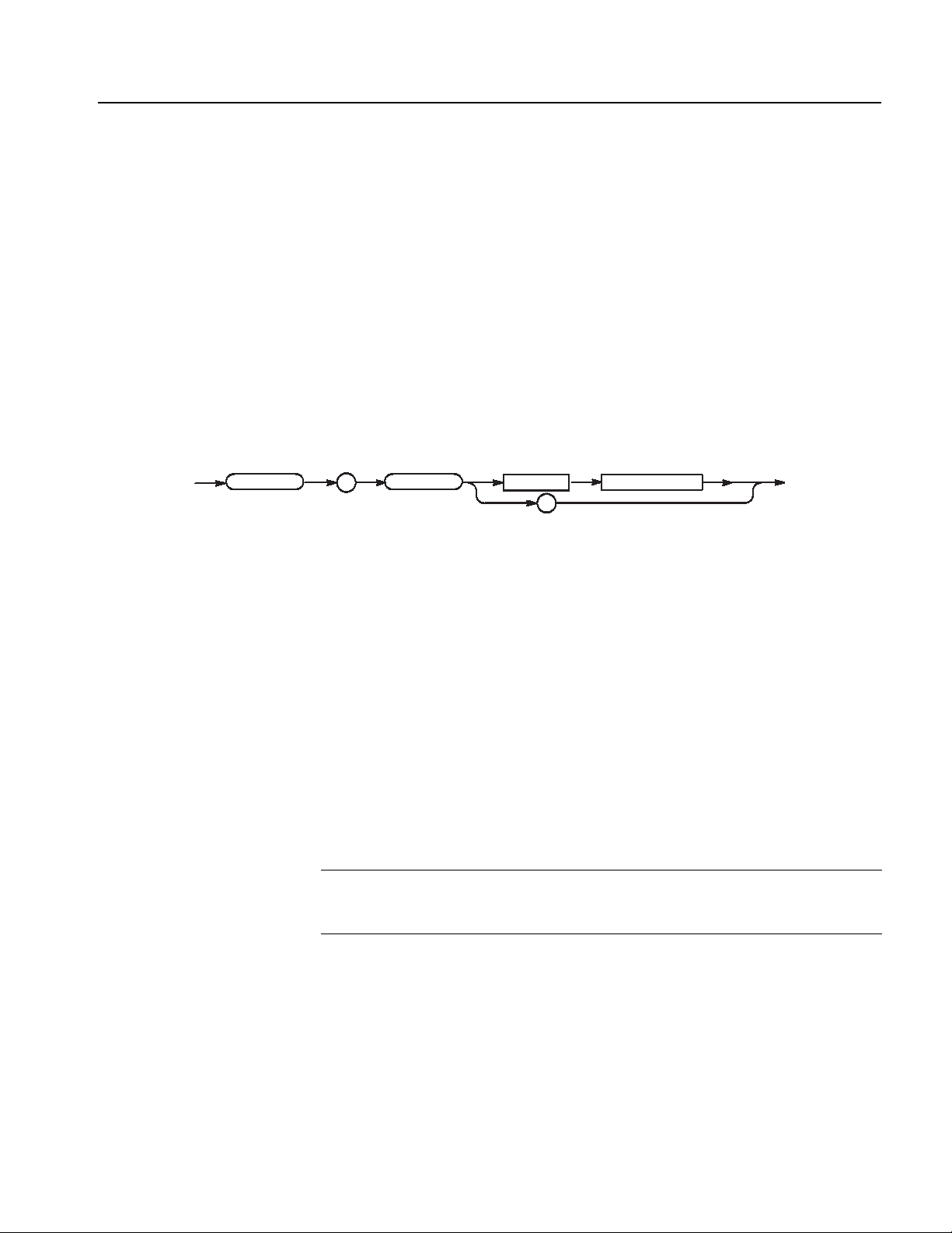
Syntax Diagrams
The syntax of each command and query is explained by both syntax diagrams and
BNF notation. Figure 2-5 shows some typical syntax diagram structures. The
syntax diagrams are described by the following symbols and notation:
Oval symbols contain literal elements, such as a command or query header and
a nonquoted string argument.
Circle symbols contain separators or special symbols, such as (:), (,), and (?).
Box symbols contain the defined element, such as <NR1>.
Arrow symbols connect elements to show the paths that can be taken through
the diagram and, thereby, the order in which the elements can be sent in a
command structure.
Parallel paths show that only one of the paths can be taken in the command.
See diagram 1 in Figure 2-5.
A loop around an element(s) shows the element can be repeated. See diagram
2 in Figure 2-5.
A path around a group of elements shows that those elements are optional. See
diagram 3 in Figure 2-5.
NOTE. The unit and SI prefix that can be added to decimal numeric arguments are
not described in the syntax diagram. See Unit and SI Prefix on page 2-7.
Diagram 1
Diagram 2
Diagram 3
Figure 2-5: Typical syntax diagrams
2-12 DTG5000 Series Data Timing Generators Programmer Manual

Command Groups
This section lists commands in two ways, by functional groups and alphabetically.
The functional group list starts below. The alphabetical list provides more detail on
each command and starts on page 2-21.
The GPIB interface of DTG5000 Series conforms to SCPI (Standard Commands
for Programmable Instruments) 1999.0 and IEEE Std 488.2-1992, except where
noted.
Functional Groups
Table 2-4 lists the functional groups into which the DTG5000 Series Data Timing
Generator commands are classified.
Table 2-4: Functional groups in the DTG command set
Group Function
Common Commands General commands to a GPIB instrument
Device Commands Specific to the DTG5000 Series.
DTG5000 Series Data Timing Generators Programmer Manual 2-13

Command Groups
Command Quick Reference
Be sure that this page through page 2-115, list all the commands in each functional
group and can be copied for use as a quick reference.
Common Commands
*CAL?
CALibration[:ALL] (?)
*CLS
DIAGnostic:DATA?
DIAGnostic:IMMediate (?)
DIAGnostic:SELect (?)
*ESE (?)
*ESR?
*IDN?
*OPC (?)
*OPT?
*RST
*SRE (?)
*STB?
SYSTem:ERRor[:NEXT]?
SYSTem:KLOCk (?)
SYSTem:VERSion?
*TRG
*TST?
*WAI
2-14 DTG5000 Series Data Timing Generators Programmer Manual

Command Groups
Device Commands
BLOCk:DELete
BLOCk:DELete:ALL
BLOCk:LENGth (?)
BLOCk:NEW
BLOCk:SELect (?)
GROup:DELete
GROup:DELete:ALL
GROup:NEW
GROup:WIDTh (?)
JGENeration:AMPLitude (?)
JGENeration:AMPLitude:UNIT (?)
JGENeration:EDGE (?)
JGENeration:FREQuency (?)
JGENeration:GSOurce (?)
JGENeration:MODE (?)
JGENeration:PROFile (?)
JGENeration[:STATe] (?)
MMEMory:LOAD
MMEMory:STORe
OUTPut:CLOCk:AMPLitude (?)
OUTPut:CLOCk:OFFSet (?)
OUTPut:CLOCk[:STATe] (?)
OUTPut:CLOCk:TIMPedance (?)
OUTPut:CLOCk:TVOLtage (?)
OUTPut:DC:HLIMit (?)
OUTPut:DC:LEVel (?)
OUTPut:DC:LIMit (?)
OUTPut:DC:LLIMit (?)
OUTPut:DC[:STATe] (?)
OUTPut:STATe:ALL
PGEN<x>[m]:CH<n>:AMODe (?)
PGEN<x>[m]:CH<n>:AMPLitude (?)
PGEN<x>[m]:CH<n>:BDATa (?)
PGEN<x>[m]:CH<n>:CPOint (?)
PGEN<x>[m]:CH<n>:DATA (?)
PGEN<x>[m]:CH<n>:DCYCle (?)
PGEN<x>[m]:CH<n>:DTOFfset (?)
PGEN<x>[m]:CH<n>:DTOFfset:STATe (?)
PGEN<x>[m]:CH<n>:HIGH (?)
PGEN<x>[m]:CH<n>:HLIMit (?)
PGEN<x>[m]:CH<n>:IMPedance (?)
PGEN<x>[m]:CH<n>:JRANge (?)
PGEN<x>[m]:CH<n>:LDELay (?)
PGEN<x>[m]:CH<n>:LHOLd (?)
PGEN<x>[m]:CH<n>:LIMit (?)
PGEN<x>[m]:CH<n>:LLIMit (?)
PGEN<x>[m]:CH<n>:LOW (?)
PGEN<x>[m]:CH<n>:OFFSet (?)
PGEN<x>[m]:CH<n>:OUTPut (?)
PGEN<x>[m]:CH<n>:PHASe (?)
PGEN<x>[m]:CH<n>:POLarity (?)
PGEN<x>[m]:CH<n>:PRATe (?)
PGEN<x>[m]:CH<n>:SLEW (?)
PGEN<x>[m]:CH<n>:TDELay (?)
PGEN<x>[m]:CH<n>:THOLd (?)
PGEN<x>[m]:CH<n>:TIMPedance (?)
PGEN<x>[m]:CH<n>:TVOLtage (?)
PGEN<x>[m]:CH<n>:TYPE (?)
PGEN<x>[m]:CH<n>:WIDTh (?)
PGEN<x>[m]:ID?
SEQuence:DATA (?)
SEQuence:LENGth (?)
SIGNal:ASSign (?)
SIGNal: <parameter> (?)
SIGNal:BDATa (?)
SIGNal:DATA (?)
SIGNal:IMPedance?
SIGNal:JRANge (?)
SUBSequence:DATA (?)
SUBSequence:DELete
SUBSequence:DELete:ALL
SUBSequence:LENGth (?)
SUBSequence:NEW
SUBSequence:SELect (?)
TBAS:COUNt (?)
TBAS:CRANge (?)
TBAS:DOFFset (?)
TBAS:EIN:IMMediate
TBAS:EIN:IMPedance (?)
TBAS:EIN:LEVel (?)
TBAS:EIN:POLarity (?)
TBAS:FREQuency (?)
TBAS:JMODe (?)
TBAS:JTIMing (?)
TBAS:JUMP
TBAS:LDELay (?)
TBAS:MODE (?)
TBAS:OMODe (?)
TBAS:PERiod (?)
TBAS:PRATe?
TBAS:RSTate?
TBAS:RUN (?)
TBAS:SMODe (?)
TBAS:SOURce (?)
TBAS:TIN:IMPedance (?)
TBAS:TIN:LEVel (?)
TBAS:TIN:SLOPe (?)
TBAS:TIN:SOURce (?)
TBAS:TIN:TIMer (?)
TBAS:TIN:TRIGger
TBAS:VRATe?
VECTor:BDATa (?)
VECTor:BIOFormat (?)
VECTor:DATA (?)
VECTor:IMPort
VECTor:IMPort:AWG
VECTor:IOFormat (?)
DTG5000 Series Data Timing Generators Programmer Manual 2-15

Command Groups
Command Summaries
Table 2-5 and Table 2-6 describe each command in each of the 2 functional groups.
Common Commands
The Common Commands are general commands to a GPIB instrument or other
equivalent equipment.
Table 2-5: Common Commands
Header Description
*CAL? Runs all the calibrations and returns the result.
CALibration[:ALL](?) Runs all the calibrations.
*CLS Clears the event-related registers and queues.
DIAGnostic:DATA? Reads the result of a self-test.
DIAGnostic:IMMediate(?) Starts a self-test.
DIAGnostic:SELect (?) Selects the self-test item to run.
*ESE(?) Sets the Service Request Enable Register
(SRER).
*ESR? Queries the value of the Standard Event Status
Register (SESR).
*IDN? Returns the model name and other information.
*OPC(?) Inserts a waiting time before all the processes
end.
*OPT? Queries the instrument options.
*RST Initializes the instrument settings.
*SRE(?) Sets the Service Request Enable Register
(SRER).
*STB? Queries the value of the Status Byte Register
(SBR).
SYSTem:ERRor[:NEXT]? Fetches the next item from the Error/Event Queue.
SYSTem:KLOCk(?) Locks the controls of the front panel and keyboard.
SYSTem:VERSion? Queries the SCPI version.
*TRG Generates a trigger.
*TST? Runs a self-test and returns the result.
*WAI Inserts a waiting time before all the currently active
commands end.
2-16 DTG5000 Series Data Timing Generators Programmer Manual

Command Groups
Device Commands
The device commands are peculiar to the DTG5000 Series.
Table 2-6: Device Commands
Header Description
BLOCk:DELete Deletes a block.
BLOCk:DELete:ALL Deletes all the blocks.
BLOCk:LENGth(?) Sets the block length.
BLOCk:NEW Creates a new block.
BLOCk:SELect(?) Selects a block used to transfer or import pattern
data.
GROup:DELete Deletes a group.
GROup:DELete:ALL Deletes all the groups.
GROup:NEW Creates a new group.
GROup:WIDTh(?) Sets the width of a group in bits.
JGENeration:AMPLitude(?) Sets the amplitude used for jitter generation.
JGENeration:AMPLitude:UNIT(?) Sets the default unit of the amplitude used for jitter
generation.
JGENeration:EDGE(?) Sets the edge used for jitter generation.
JGENeration:FREQuency(?) Sets the frequency used for jitter generation.
JGENeration:GSOurce(?) Sets the gating source used for jitter generation.
JGENeration:MODE(?) Sets the mode used for jitter generation.
JGENeration:PROFile(?) Sets the profile used for jitter generation.
JGENeration[:STATe] (?) Turns on or off jitter generation.
MMEMory:LOAD Loads the settings file.
MMEMory:STORe Saves the current settings in a file.
OUTPut:CLOCk:AMPLitude(?) Sets the clock output amplitude.
OUTPut:CLOCk:OFFSet(?) Sets the clock output offset.
OUTPut:CLOCk[:STATe](?) Turns on or off the clock output.
OUTPut:CLOCk:TIMPedance(?) Sets the clock output termination impedance.
OUTPut:CLOCk:TVOLtage(?) Sets the clock output termination voltage.
OUTPut:DC:HLIMit(?) Sets the high limit of the DC output.
OUTPut:DC:LEVel(?) Sets the DC output level.
OUTPut:DC:LIMit(?) Turns on or off the DC output limit.
OUTPut:DC:LLIMit(?) Sets the low limit of the DC output.
OUTPut:DC[:STATe](?) Turns on or off the DC output.
DTG5000 Series Data Timing Generators Programmer Manual 2-17

Command Groups
Table 2-6: Device Commands (cont.)
Header Description
OUTPut:STATe:ALL Turns on or off all outputs.
PGEN<x>[m]:CH<n>:AMODe(?) Sets the channel composition mode for the data
output.
PGEN<x>[m]:CH<n>:AMPLitude(?) Sets the data output amplitude.
PGEN<x>[m]:CH<n>:BDATa(?) Transfers pattern data in binary format.
PGEN<x>[m]:CH<n>:CPOint(?) Sets the Cross Point of the NRZ.
PGEN<x>[m]:CH<n>:DATA(?) Transfers pattern data.
PGEN<x>[m]:CH<n>:DCYCle(?) Sets the data output duty cycle.
PGEN<x>[m]:CH<n>:DTOFfset(?) Sets the differential timing offset value for the data
output.
PGEN<x>[m]:CH<n>:DTOFfset:
STATe(?)
PGEN<x>[m]:CH<n>:HIGH(?) Sets the high level of the data output.
PGEN<x>[m]:CH<n>:HLIMit(?) Sets the high limit of the data output.
PGEN<x>[m]:CH<n>:IMPedance? Examines the output impedance of the DTGM21.
PGEN<x>[m]:CH<n>:JRANge(?) Sets the jitter range of the DTGM32.
PGEN<x>[m]:CH<n>:LDELay(?) Sets the lead delay of the data output.
PGEN<x>[m]:CH<n>:LHOLd(?) Specifies how the data output leading edge is held.
PGEN<x>[m]:CH<n>:LIMit(?) Sets whether the limit is applied.
PGEN<x>[m]:CH<n>:LLIMit(?) Sets the low limit of the data output level.
PGEN<x>[m]:CH<n>:LOW(?) Specifies the low level of the data output.
PGEN<x>[m]:CH<n>:OFFSet(?) Sets the offset level of the data output.
PGEN<x>[m]:CH<n>:OUTPut(?) Turns on or off the data output.
PGEN<x>[m]:CH<n>:PHASe(?) Sets the data output phase.
PGEN<x>[m]:CH<n>:POLarity(?) Sets the polarity of the data output.
PGEN<x>[m]:CH<n>:PRATe(?) Sets the pulse rate.
PGEN<x>[m]:CH<n>:SLEW(?) Sets the slew rate of the data output.
PGEN<x>[m]:CH<n>:TDELay(?) Sets the trail delay of the data output.
PGEN<x>[m]:CH<n>:THOLd(?) Specifies how to hold the data output trailing edge.
PGEN<x>[m]:CH<n>:TIMPedance(?) Sets the data output termination impedance.
PGEN<x>[m]:CH<n>:TVOLtage(?) Sets the data output termination voltage.
PGEN<x>[m]:CH<n>:TYPE(?) Sets the format of data output in DG mode.
PGEN<x>[m]:CH<n>:WIDTh(?) Sets the data output pulse width.
PGEN<x>[m]:ID? Examines the module.
Turns on or off the data output differential timing.
2-18 DTG5000 Series Data Timing Generators Programmer Manual

Command Groups
Table 2-6: Device Commands (cont.)
Header Description
SEQuence:DATA(?) Sets the data corresponding to one line of a
sequence.
SEQuence:LENGth(?) Sets the sequence length.
SIGNal:ASSign(?) Assigns a physical channel to the logical channel
specified with the group name and bit number.
SIGNal:<parameter>(?) Sets the data output parameters using a signal
name.
SIGNal:BDATa(?) Transfers pattern data in binary format.
SIGNal:DATA(?) Transfers pattern data.
SIGNal:IMPedance? Examines the output impedance of the DTGM21.
SIGNal:JRANge(?) Sets the jitter range of the DTGM32.
SUBSequence:DATA(?) Sets the data corresponding to one line of a
subsequence.
SUBSequence:DELete Deletes a subsequence.
SUBSequence:DELete:ALL Deletes all the subsequences.
SUBSequence:LENGth(?) Changes the subsequence length.
SUBSequence:NEW Creates a new subsequence.
SUBSequence:SELect(?) Selects a subsequence.
TBAS:COUNt(?) Sets the burst count.
TBAS:CRANge(?) Sets the clock range.
TBAS:DOFFset(?) Sets the delay offset.
TBAS:EIN:IMMediate Generates an event.
TBAS:EIN:IMPedance(?) Sets the event input impedance.
TBAS:EIN:LEVel(?) Sets the event input level.
TBAS:EIN:POLarity(?) Sets the polarity of the event input.
TBAS:FREQuency(?) Sets the frequency.
TBAS:JMODe(?) Sets the jump mode.
TBAS:JTIMing(?) Sets the jump timing.
TBAS:JUMP Causes a software jump.
TBAS:LDELay(?) Sets the long delay.
TBAS:MODE(?) Sets the PG run mode.
TBAS:OMODe(?) Sets the operating mode.
TBAS:PERiod(?) Sets the frequency.
TBAS:PRATe? Queries the PLL multiplier rate.
TBAS:RSTate? Queries the sequencer status.
DTG5000 Series Data Timing Generators Programmer Manual 2-19

Command Groups
Table 2-6: Device Commands (cont.)
Header Description
TBAS:RUN(?) Starts and stops the sequencer.
TBAS:SMODe(?) Sets the sequencer mode.
TBAS:SOURce(?) Sets the clock source.
TBAS:TIN:IMPedance(?) Sets the trigger input impedance.
TBAS:TIN:LEVel(?) Sets the trigger input level.
TBAS:TIN:SLOPe(?) Sets the polarity of the trigger input.
TBAS:TIN:SOURce(?) Sets the trigger input source.
TBAS:TIN:TIMer(?) Sets the cycle of the internal trigger.
TBAS:TIN:TRIGger Generates a trigger.
TBAS:VRATe? Queries the vector rate.
VECTor:BDATa(?) Transfers pattern data in binary format.
VECTor:BIOFormat(?) Sets the data items to be transferred with
VECTor:BDATa.
VECTor:DATA(?) Transfers pattern data in ASCII format.
VECTor:IMPort Read pattern data from a file.
VECTor:IMPort:AWG Imports pattern data from an AWG series file.
VECTor:IOFormat(?) Sets the data items to be transferred with VECT or
DATA and their format.
2-20 DTG5000 Series Data Timing Generators Programmer Manual

Command Descriptions
BLOCCkk
:
ELete
:
L
This subsection lists each command and query in the data timing generator
command set in alphabetical order. Each command entry includes a command
description and command group, related commands (if any), syntax, and
arguments. Each entry also includes one or more usage examples.
This subsection fully spells out headers, mnemonics, and arguments with the
minimal spelling shown in upper case. For example, to use the abbreviated
version of the BLOCk:DELete command, just type BLOC:DEL.
The symbol “(?)” follows the command header of commands that can be used as
either a command or a query; the symbol “?” follows commands that can only be
used as a query. Commands that are command-only or query-only are noted as
such.
BLOCk:DELete (No Query Form)
This command deletes a block.
Syntax
Arguments
Examples
BLOCk:DELete <block_name>
BLOCk
<block_name> ::= <string> - Block name
BLOCk:DELete"Block1"
Deletes the block named “Block1”.
BLOCk:DELete:ALL (No Query Form)
This command deletes all the blocks.
Syntax
Arguments
BLOCk:DELete:ALL
BLO
None
:
:
DELete
DDELete
<space> <block_name>
:
ALALL
DTG5000 Series Data Timing Generators Programmer Manual 2-21

Command Descriptions
BLOCCkk
:
W
pace>
<block_length>
<block_namee>>
,
Examples
BLOCk:LENGth (?)
Syntax
BLOCk
:
Arguments
BLOCk:DELete:ALL
Deletes all the blocks.
This command sets the block length.
BLOCk:LENGth <block_name>, <block_length>
BLOCk:LENGth? <block_name>
LENGth <space>
?
<block_name>
<space>
,
<block_name>
<block_name> ::= <string> - Block name
<block_length> ::= <Numeric> - The range is as follows:
DTG 5078: 1 to 8,000,000
DTG 5274: 1 to 32,000,000
DTG 5334: 1 to 64,000,000
<block_length>
Examples
BLOCk:LENGth "Block1",960
Sets the block length of “Block1” to 960.
BLOCk:LENGth? "Block2"
Queries the block length of “Block2”.
If the block name is not found, the following will be returned: -1
BLOCk:NEW (No Query Form)
This command creates a new block.
BLOCk:NEW <block_name>, <block_length>
NENEW
<block_name> ::= <string> - The block name consists of 32 characters or less.
<block_length> ::= <Numeric> - The range is as follows:
DTG 5078: 1 to 8,000,000
DTG 5274: 1 to 32,000,000
DTG 5334: 1 to 64,000,000
BLO
Syntax
:
Arguments
<s<space>
<block_nam
,
<block_length>
2-22 DTG5000 Series Data Timing Generators Programmer Manual
You can create up to 8,000 blocks.
Command Descriptions
Examples
BLOCk:SELect (?)
Syntax
BLOCk
Arguments
Examples
BLOCk:NEW "Block1",960
Creates a block with a length of 960 under the name of “Block1”.
This command selects a block used to transfer or import pattern data.
BLOCk:SELect <block_name>
BLOCk:SELect?
:
SELect <space>
?
<block_name>
<block_name> ::= <string> - Block name
*RST returns the setting to “”.
BLOCk:SELect "Block1"
Selects a block named “Block1”.
*CAL? (Query Only)
Syntax
The *CAL? query performs a level calibration and returns a status that indicates
whether or not the data timing generator completed the calibration successfully. If
an error is detected during calibration, execution immediately stops, and an error
code is returned. This query performs the same function as the
CALibration[:ALL]? query.
NOTE. A period of time is required to complete the internal calibration. During this
time, the data timing generator does not respond to any commands or queries
issued.
*CAL?
DTG5000 Series Data Timing Generators Programmer Manual 2-23

Command Descriptions
Arguments
Returns
Examples
CALibration[:ALL] (?)
*CAL
?
None
<NR1>
0 Terminated without error.
-340 Calibration failed.
*CAL?
performs an internal calibration and returns the results. For example, the query
might return 0, which indicates the calibration terminated without any errors.
The CALibration[:ALL] command performs a level calibration of the data
timing generator.
The CALibration[:ALL]? query performs a level calibration and responds with
an <NR1> indicating the success of the calibration. This query has the same
function as the *CAL? query.
Syntax
Arguments
Returns
If an error is detected during calibration, a message is queued in the error/event
queue, and the error code “-340” is returned.
NOTE. A period of time is required to complete the internal calibration. During this
time, the data timing generator does not respond to any commands or queries
issued.
CALibration[:ALL]
CALibration[:ALL]?
:
CALibration
ALL
?
None
<NR1>
0 Terminated without error.
-340 Calibration failed.
2-24 DTG5000 Series Data Timing Generators Programmer Manual

Command Descriptions
DIAGnoossttiicc
:
A
?
Examples
*CLS (No Query Form)
Syntax
CALibration[:ALL]?
performs a level calibration and returns the results. For example, it might return 0,
which indicates the calibration terminated without any errors.
CALibration[:ALL]
performs a level calibration.
In the case, when it becomes a error, the SYSTem:ERRor[:NEXT]? command can be
checked the error information.
Detailed information continues after that by an event number -340 and “Calibration
failed”.
This command clears all the event registers and queues, used by the data timing
generator status and event reporting system. For more details, refer to the, Status
and Events section.
*CLS
*CLS
Arguments
Examples
None
*CLS
clears all the event registers and queues.
DIAGnostic:DATA? (Query Only)
This command returns the results of a self–test.
Syntax
Arguments
DIAGnostic:DATA?
DIAGn
None
:
DADATTA
?
DTG5000 Series Data Timing Generators Programmer Manual 2-25

Command Descriptions
Returns
<NR1>
0 Terminated without error.
-330 Self-test failed.
Examples
DIAGnostic:DATA?
might return 0.
DIAGnostic:IMMediate (?)
The DIAGnostic:IMMediate command executes the self-test routine(s) selected
by the DIAGnostic:SELect command. The query DIAGnostic:IMMediate?
executes the routine(s) and returns the results.
If an error is detected during execution, the routine that detected the error
terminates. If all of the self-test routines are selected, self-testing continues with
execution of the next self-test routine.
The command without “?” perform a self test simply. In the case, when it
becomes a dialog error, an event occurs. Detailed information continues after that
by an event number -330 and “Self test failed”. Detailed information is the set of a
dialog error code and auxiliary information, and is the same contents as what is
displayed on a screen.
Syntax
Arguments
Returns
Examples
A result can be checked by DIAGnostic:DATA?.
DIAGnostic:IMMediate
DIAGnostic:IMMediate?
DIAGnostic
:
IMMediate
?
None
<NR1>
0 Terminated without error.
-330 Self-test failed.
DIAGnostic:SELect ALL;IMMediate?
executes all of the self-test routines. After all self-test routines finish, the results of
the self-tests are returned.
2-26 DTG5000 Series Data Timing Generators Programmer Manual

DIAGnostic:SELect (?)
Command Descriptions
This command selects the self–test routine(s).
Syntax
DIAGnostic
Arguments
DIAGnostic:SELect { ALL | CLOCk | OUTPut | REGister | SMEMory |
PMEMory }
DIAGnostic:SELect?
ALL
CLOCk
OUTput
REGister
SMEMory
<space>
:
SELect
PMEMory
?
You can select the following self–test routines:
Table 2-7: Self–test routines
Argument Description
ALL Checks all routines that follow
CLOCk Checks the clock unit
OUTput Checks the output unit
REGister Checks the register unit
SMEMory Checks the sequence memory
PMEMory Checks the pattern memory
At *RST, this parameter is set to ALL.
Examples
DIAGnostic:SELect SMEMory;IMMediate
executes the sequence memory self–test routine.
DTG5000 Series Data Timing Generators Programmer Manual 2-27

Command Descriptions
*ESRR
?
*ESE (?)
The *ESE command sets the bits of the ESER (Event Status Enable Register)
used in the status and events reporting system of the data timing generator. The
*ESE? query returns the contents of the ESER. Refer to the Status and Events for
more information about the ESER.
Syntax
Arguments
Examples
*ESE <bit_value>
*ESE?
*ESE <space>
?
<bit_value>
<bit_value>::=<NR1>
where <NR1> is a decimal integer in the range 0 to 255. The binary bits of the
ESER are set according to this value.
The power–on default for ESER is 0 if *PSC is 1. If *PSC is 0, the ESER
maintains its value through a power cycle.
*ESE 177
sets the ESER to 177 (binary 10110001), which sets the PON, CME, EXE and OPC
bits.
*ESE?
might return 176, which indicates that the ESER contains the binary number
10110000.
*ESR? (Query Only)
This command returns the contents of the Standard Event Status Register (SESR)
used in the status and events reporting system in the data timing generator. *ESR?
also clears the SESR (since reading the SESR clears it). Refer to Section 3 Status
and Events for more information.
Syntax
Returns
2-28 DTG5000 Series Data Timing Generators Programmer Manual
*ESR?
*ES
?
<NR1> indicates the content of the SESR in a decimal integer.

Command Descriptions
Examples
*ESR?
might return 181, which indicates that the SESR contains the binary number
10110101.
GROup:DELete (No Query Form)
This command deletes a group.
Syntax
Arguments
Examples
GROup:DELete <group_name>
GROup
<group_name> ::= <string> - Group name
GROup:DELete ”Group1”
Deletes a group named “Group1”.
GROup:DELete:ALL (No Query Form)
:
DELete
<space> <group_name>
Syntax
Arguments
Examples
This command deletes all the groups.
GROup:DELete:ALL
GROup
:
DELete
None
GROup:DELete:ALL
Deletes all the groups.
:
ALL
DTG5000 Series Data Timing Generators Programmer Manual 2-29

Command Descriptions
p
:
h
pace>
<gr
oup_w
idth>
<gr
oup_namee>>
,
?
pace>
<gr
oup_namee>>
GROup:NEW (No Query Form)
This command creates a new group.
Syntax
GROup
Arguments
Examples
GROup:WIDTh (?)
Syntax
GROup:NEW <group_name>, <group_width>
:
NEW <space>
<group_name>
,
<group_width>
<group_name> ::= <string> - The group name consists of 32 characters or less.
<group_width> ::= <Numeric> - The range is 1 to 96.
You can create up to 96 groups.
GROup:NEW "Group1",8
Creates a group with an 8-bit width under the name of “Group1”.
This command sets the width of a group in bits.
GROup:WIDth <group_name>, <group_width>
GROup:WIDth? <group_name>
<gr
oup_w
GRGROuOup
:
Arguments
WIWIDDtth
<s<space>
?
<gr
<s<space>
oup_nam
<group_name> ::= <string> - Group name
<gr
,
oup_nam
idth>
<group_width> ::= <Numeric> - The range is 1 to 96.
Returns
Examples
<NR1>
GROup:WIDTh "Group1",4
Sets the width of “Group1” to 4 bits.
If the group name is not found when queries the width of a group, the following
will be returned: -1
2-30 DTG5000 Series Data Timing Generators Programmer Manual

*IDN? (Query Only)
ation
:
itude
pace>
umer
ic>
?
Command Descriptions
This command returns identification information for the data timing generator.
Syntax
Arguments
Returns
*IDN?
None
<manufacturer>, <model>, <serial_number>, <firmware_level>
where
<manufacturer>::=Tektronix
<model>::={ DTG5274 | DTG5078 | DTG5334 }
<serial_number>::=Jxxxxxx - xxxxxx indicates an actual serial number
<firmware_level>::=SCPI:99.0, FW:x.x.x - System software version
Examples
*IDN?
might return TEKTRONIX,DTG5078,0,SCPI:99.0 FW:1.0
JGENeration:AMPLitude (?)
This command sets the amplitude used for jitter generation.
*IDN
?
Syntax
JGENeration:AMPLitude <Numeric>
JGENeration:AMPLitude?
JJGGENENereration
Arguments
:
AAMMPPLLitude
<s<space>
?
<N<Numer
ic>
For the unit for setting, you can specify SPP, SRMS, UIPP, or UIRMS.
If you omit the unit, the system assumes that there is a unit you specified in
JGENeration:AMPLitude:UNIT. For the meanings of units, see the description of
JGENeration:AMPLitude:UNIT.
For the setting range, refer to the reference manual (the calculation is complicated).
The range is difficult to calculate, please refer to the reference manual (Chapter 2
Reference: “Output Level” Section). You can query the minimum value and the
maximum value by the use of MIN/MAX command.
*RST returns the setting to 0 (unit: SPP).
DTG5000 Series Data Timing Generators Programmer Manual 2-31

Command Descriptions
Returns
Examples
<NR3>
JGENeration:AMPLitude 1e-10
Sets the amplitude for jitter generation to 100ps when UNIT is SPP.
JGENeration:AMPLitude? MAX
Query the maximum amplitude for jitter generation at the current unit.
JGENeration:AMPLitude:UNIT (?)
This command sets the default unit of the amplitude used for jitter generation.
This command specifies the default unit that is added when a numeric without unit
is sent with JGENeration:AMPLitude. Also when a query is performed with
JGENeration:AMPLITude?, the unit you specified in this command is added.
In addition, this command also specifies whether s (second) or UI (unit interval)
is used as the unit that is used to retain the value when you change the frequency.
If you specify SPP or SRMS, s will be used. If you specify UIPP or UIRMS, UI
will be used.
Syntax
JGENeration:AMPLitude:UNIT <amplitude unit>
JGENeration:AMPLitude:UNIT?
JGENeration
Arguments
<space>
:
AMPLitude
:
UNIT
<amplitude unit> ::= {SPP | SRMS | UIPP | UPRMS}
SPP - Represents the peak to peak value in seconds (s).
SRMS - Represents the root mean square (effective value) in seconds (s).
UIPP - Represents the peak to peak value in unit intervals (UI).
UIRMS - Represents the root mean square (effective value) in unit intervals (UI).
*RST returns the setting to 0 (unit: SPP).
SPP
SRMS
UIPP
UIRMS
?
2-32 DTG5000 Series Data Timing Generators Programmer Manual

Command Descriptions
Returns
Examples
JGENeration:EDGE (?)
Syntax
JGENeration
<amplitude unit>
JGENeration:AMPLitude:UNIT SRMS
Sets SRMS for the default unit of the amplitude used for jitter generation.
This command sets the edge used for jitter generation.
JGENeration:EDGE { RISe | FALL | BOTH }
JGENeration:EDGE?
RISe
FALL
<space>
:
EDGE
BOTH
?
Arguments
Returns
Examples
RISe: Sets the edge to rising.
FALL: Sets the edge to falling.
BOTH: Sets the edge to both rising and falling.
*RST sets the edge to BOTH.
{ RISe | FALL | BOTH }
JGENeration:EDGE RISe
Sets rising for the edge used for jitter generation.
DTG5000 Series Data Timing Generators Programmer Manual 2-33

Command Descriptions
JGENeration:FREQuency (?)
This command sets the frequency used for jitter generation (other than GNOise).
Syntax
JGENeration:FREQuency <Numeric>
JGENeration:FREQuency?
JGENeration
Arguments
Range: 0.015 Hz to 1.56 MHz
Step: 1e-3 Hz
*RST returns the setting to 1e6 Hz.
Returns
Examples
<NR3>
JGENeration:FREQuency 1MHz
Sets 1 MHz for the frequency used for jitter generation.
JGENeration:GSOurce (?)
This command sets the gating source, that is, the group and bit to which to apply
the jitter.
:
FREQuency <space>
<Numeric>
?
Syntax
JGENeration:GSOurce <logical_channel>
JGENeration:GSOurce?
JGENeration
Arguments
:
GSOurce <space>
?
<logical_channel>
<logical_channel> ::= <string> - Logical channel. Use one of the following
formats:
<group_name> - For a group with a 1-bit width
<group_name>[<bit>] - Specified bit number in the specified group (This
“[]” can’t omit).
2-34 DTG5000 Series Data Timing Generators Programmer Manual

Command Descriptions
Example:
CLK
Addr[0]
The jitter will be applied only to Channel 1 of Slot A of the master.
*RST returns the setting to “”.
Returns
Examples
JGENeration:MODE (?)
Syntax
JGENeration
Arguments
<logical_channel>
JGENeration:GSOurce "Group1[0]"
Sets the jitter generation gating source in Bit 0 of “Group1”.
This command sets the mode used for jitter generation.
JGENeration:MODE {ALL | PARTial}
JGENeration:MODE?
ALL
<space>
:
MODE
PARTial
?
ALL: Applies the jitter to the entire output signal.
PARTial: Applies the jitter to part of the output signal.
*RST returns the setting to ALL.
Returns
Examples
{ ALL | PARTial }
JGENeration:MODE ALL
Applies the jitter to the entire output signal.
DTG5000 Series Data Timing Generators Programmer Manual 2-35

Command Descriptions
JGENeration:PROFile (?)
This command sets the profile used for jitter generation.
Syntax
Arguments
JGENeration:PROFile <jitter_profile>
JGENeration:PROFile?
SINusoid
SQUare
TRIangle
JGENeration
<space>
:
PROFile
GNOise
?
<jitter_profile> - Waveform type. You can select one of the following:
SINusoid : Sine wave
SQUare : Square wave
TRIangle : Triangular wave
GNOise : Gaussian noise
*RST returns the setting to SINusoid.
Returns
Examples
<jitter_profile>
JGENeration:PROFile SQUare
Generates a jitter with a square wave.
2-36 DTG5000 Series Data Timing Generators Programmer Manual

JGENeration[:STATe] (?)
Command Descriptions
This command turns on or off jitter generation.
Syntax
Arguments
JGENeration[:STATe] {ON | OFF | <NRf>}
JGENeration[:STATe]?
ON
OFF
JGENeration
<space>
:
STATe
<NRf>
?
OFF or <NRf> = 0 - Turns off jitter generation.
ON or <NRf> ≠ 0 - Turns on jitter generation.
The jitter cannot be turned on if Long Delay in DG mode is ON and an Output
Module is not inserted in Slot A of the master. (You can set the parameters such
as the jitter amplitude even in this case.)
The jitter can be applied only to Channel 1 of Slot A of the master. Channel 2 is
disabled at this time.
*RST returns the setting to 0 (Off).
Returns
Examples
<NR1>
JGENeration:STATe ON
Turns on jitter generation.
DTG5000 Series Data Timing Generators Programmer Manual 2-37
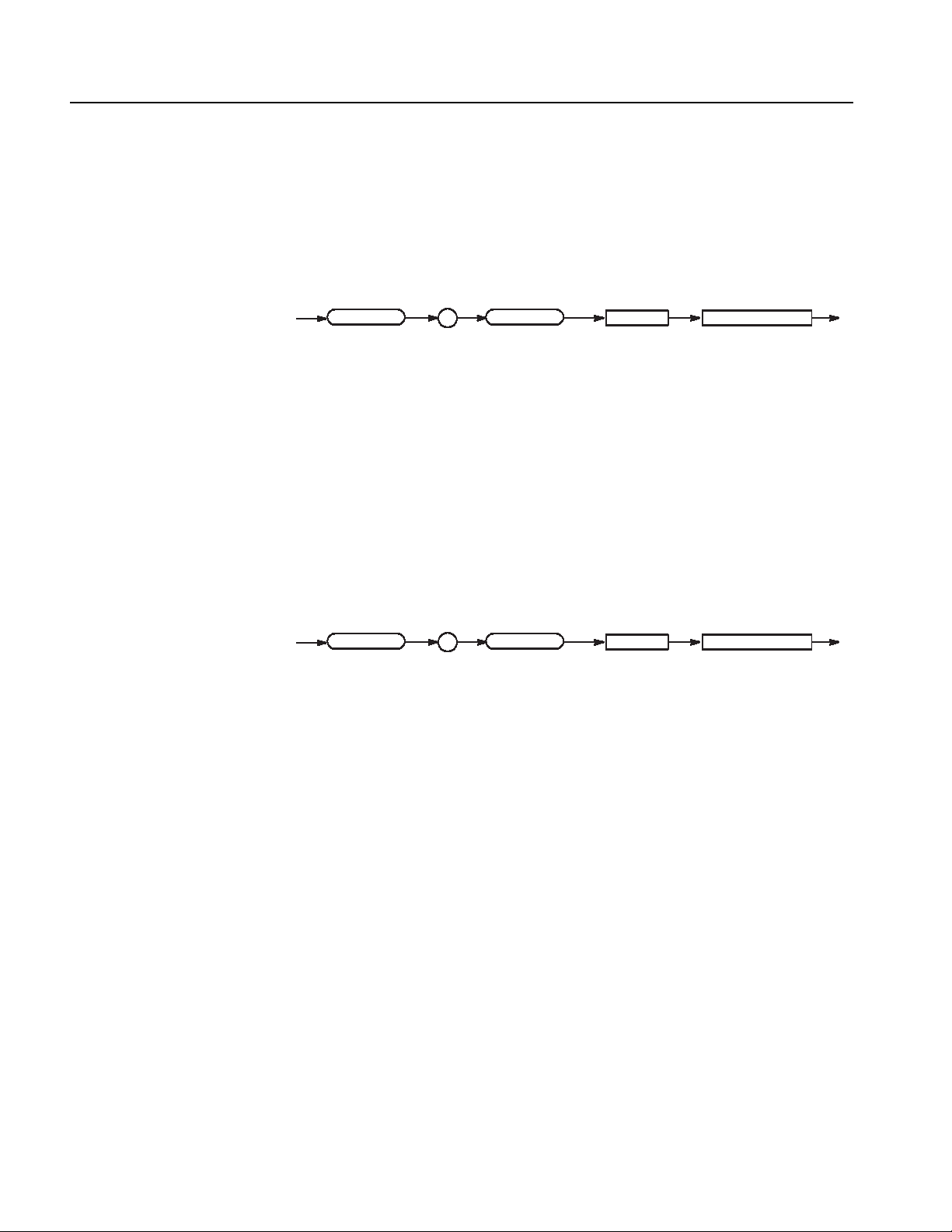
Command Descriptions
MMEMory:LOAD (No Query Form)
This command loads the settings file.
Syntax
Arguments
Examples
MMEMory:LOAD <filename>
MMEMory
<filename> ::= <string> - File name (absolute path)
MMEMory:LOAD "C:\tmp\abc.dtg"
Loads a setting file named “C:\tmp\abc.dtg”.
MMEMory:STORe (No Query Form)
This command saves the current settings in a file.
Syntax
Arguments
MMEMory:STORe <filename>
MMEMory
<filename> ::= <string> - File name (absolute path)
:
:
LOAD
STORe
<space> <filename>
<space> <filename>
Examples
MMEMory:STORe "C:\tmp\abc.dat"
Saves a setting file named “C:\tmp\abc.dat”.
*OPC (?)
Operation complete command (query). Use this command between two other
commands to ensure completion of the first command before processing the
second command.
In this application, all commands are designed to be executed in the order in
which they are sent from the external controller.
Refer to page 3-5 about the OPC bit of SESR (Standard Event Status Register).
2-38 DTG5000 Series Data Timing Generators Programmer Manual

Command Descriptions
T
?
Syntax
Arguments
Returns
Examples
*OPT? (Query Only)
*OPC
*OPC?
*OPC
?
None
<NR1> ::=1 All the active commands are complete (Operation Complete).
PGENA1:CH1:HIGH 2.0;*OPC
An end can be checked when the event of Operation Complete occurs.
PGENA1:CH1:HIGH 2.0;*OPC?
An end can be checked when 1 should be returned.
This command returns the implemented options of the data timing generator.
Syntax
Arguments
Returns
Examples
*OPT?
*O*OPPT
?
None
0
Since 0 is always returned, you do not need to use this query in actual programs.
DTG5000 Series Data Timing Generators Programmer Manual 2-39

Command Descriptions
OUTPut:CLOCk:AMPLitude (?)
This command sets the clock output amplitude.
Syntax
OUTPut:CLOCk:AMPLitude <Numeric>
OUTPut:CLOCk:AMPLitude?
OUTPut
:
Arguments
CLOCk
Range: 0.03 to 1.25 V
Step: 10 mV
*RST returns the setting to 1.0 V.
Returns
Examples
<NR3>
OUTPut:CLOCk:AMPLitude 0.5
Sets the clock output amplitude to 0.5 V.
OUTPut:CLOCk:OFFSet (?)
This command sets the clock output offset.
:
AMPLitude <space>
?
<Numeric>
Syntax
OUTPut:CLOCk:OFFSet <Numeric>
OUTPut:CLOCk:OFFSet?
OUTPut
:
Arguments
CLOCk
Range: -0.985 to 3.485 V (when the amplitude is 30 mV)
:
OFFSet <space>
?
<Numeric>
Step: 40 mV
*RST returns the setting to 0.48 V.
Returns
<NR3>
2-40 DTG5000 Series Data Timing Generators Programmer Manual

Command Descriptions
CLOCCkk
:
edance
pace>
umer
ic>
?
OUTPuPutt
:
Examples
OUTPut:CLOCk:OFFSet 0.1
Sets the clock output offset to 0.1 V.
OUTPut:CLOCk[:STATe] (?)
This command turns on or off the clock output.
Syntax
OUTPut
Arguments
OUTPut:CLOCk[:STATe] {ON | OFF | <NRf>}
OUTPut:CLOCk[:STATe]?
:
CLOCk
OFF or <NRf> = 0 - Turns off the clock output.
ON
OFF
<space>
:
STATe
<NRf>
?
ON or <NRf> ≠ 0 - Turns on the clock output.
*RST returns the setting to 0 (Off).
Returns
Examples
<NR1>
OUTPut:CLOCk:STATe ON
Turns on the clock output.
OUTPut:CLOCk:TIMPedance(?)
This command sets the clock output termination impedance.
OUTPut:CLOCk:TIMPedance <Numeric>
OUTPut:CLOCk:TIMPedance?
CLO
OUT
Syntax
:
:
TITIMMPPedance
<s<space>
?
<N<Numer
ic>
DTG5000 Series Data Timing Generators Programmer Manual 2-41
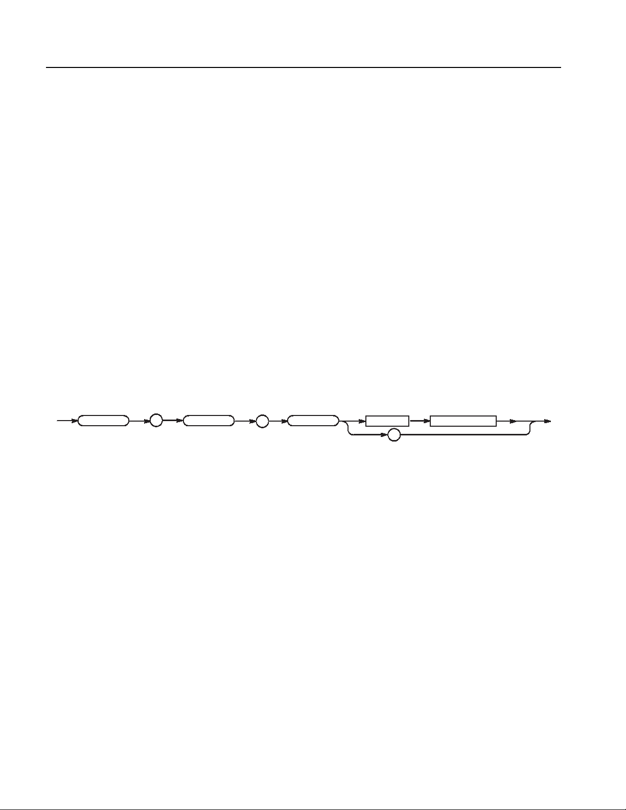
Command Descriptions
Arguments
Range: 10 ohm to 1 M ohm
≤ 0: Open
Step: 3 significant digits. The minimum resolution is 1 ohm.
*RST returns the setting to 50.0 ohm.
Returns
Examples
<NR3>
OUTPut:CLOCk:TIMPedance 40
Sets the clock output termination impedance to 40 ohm.
OUTPut:CLOCk:TVOLtage(?)
This command sets the clock output termination voltage.
Syntax
OUTPut:CLOCk:TVOLtage <Numeric>
OUTPut:CLOCk:TVOLtage?
OUTPut
:
Arguments
Returns
Examples
OUTPut:DC:HLIMit(?)
Syntax
CLOCk
:
TVOLtage <space>
?
Range: -2 to +5V
Step: 0.1 V
*RST returns the setting to 0.0 V.
<NR3>
OUTPut:CLOCk:TVOLtage 1.1
Sets the clock output termination voltage 1.1 V.
This command sets the high limit of the DC output.
OUTPut:DC:HLIMit <DC_channel>, <Numeric>
OUTPut:DC:HLIMit? <DC_channel>
<Numeric>
2-42 DTG5000 Series Data Timing Generators Programmer Manual
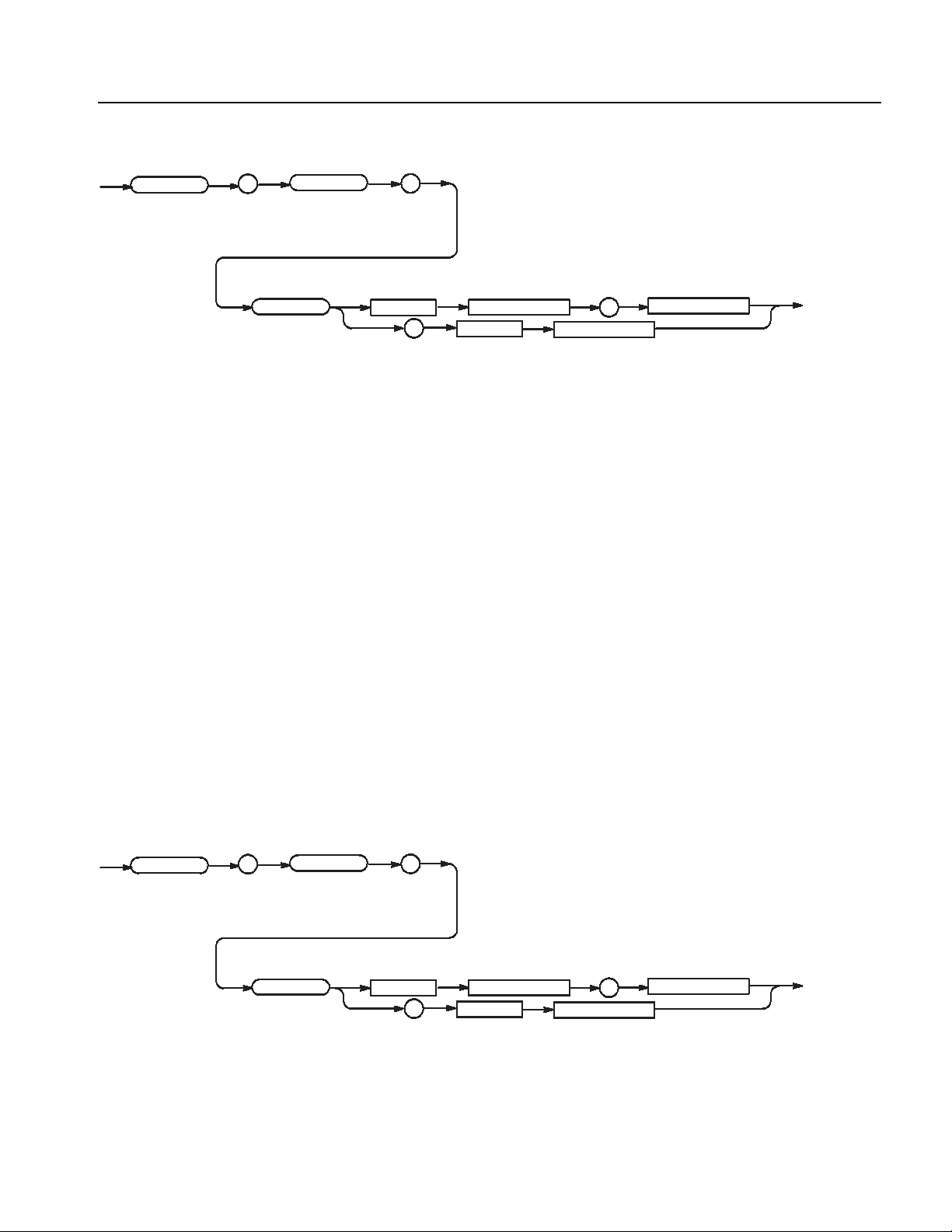
Command Descriptions
OUTPut
:
HLIMit <space>
Arguments
Returns
Examples
DC
:
<DC_channel>
?
<space>
,
<DC_channel>
<Numeric>
<DC_channel> ::= <NR1> (0 to 23, if three units are concurrently used)
<Numeric> ::= High limit - Step: 30 mV, Range: -3 to 5V
If the low limit of the DC output exceeds its high limit, the low limit will be set
to the same value as the high limit.
*RST returns the setting to 1.0 V.
<NR3>
OUTPut:DC:HLIMit 0,1.5
Sets the high limit of the DC output (0) to 1.5 V.
OUTPut:DC:LEVel(?)
Syntax
OUTPut
:
LEVel <space>
Arguments
This command sets the DC output level.
OUTPut:DC:LEVel <DC_channel>, <Numeric>
OUTPut:DC:LEVel? <DC_channel>
DC
:
<DC_channel>
?
<space>
,
<DC_channel>
<Numeric>
<DC_channel> ::= <NR1> (0 to 23, if three units are concurrently used)
<Numeric> ::= Level - Step: 30 mV, Range: Low limit to high limit of DC output
DTG5000 Series Data Timing Generators Programmer Manual 2-43

Command Descriptions
*RST returns the setting to 1.0 V.
Returns
Examples
OUTPut:DC:LIMit(?)
Syntax
OUTPut
:
<NR3>
OUTPut:DC:LEVel 0,1.1
Sets the level of the DC output (0) to 1.1 V.
This command sets the DC output level.
OUTPut:DC:LIMit <DC_channel>, { ON | OFF | <NRf> }
OUTPut:DC:LIMit? <DC_channel>
DC
:
ON
OFF
LIMit <space>
?
Arguments
<DC_channel> ::= <NR1> (0 to 23, if three units are concurrently used)
OFF or <NRf> = 0 - Turns off the DC output limit.
ON or <NRf>
*RST returns the setting to 0.
Returns
Examples
<NR1>
OUTPut:DC:LIMit 1,ON
Turns on the DC output (0) limit.
<DC_channel>
<space>
,
<DC_channel>
<space>
≠ 0 - Turns on the DC output limit.
<NRf>
2-44 DTG5000 Series Data Timing Generators Programmer Manual

OUTPut:DC:LLIMit(?)
Command Descriptions
This command sets the low limit of the DC output.
OUTPut
Syntax
:
LLIMit <space>
Arguments
OUTPut:DC:LLIMit <DC_channel>, <Numeric>
OUTPut:DC:LLIMit? <DC_channel>
DC
:
<DC_channel>
?
<space>
,
<DC_channel>
<Numeric>
<DC_channel> ::= <NR1> (0 to 23, if three units are concurrently used)
<Numeric> ::= Low limit - Step: 30 mV, Range: -3 to 5V
If the high limit of the DC output is below its low limit, the high limit will be set
to the same value as the low limit.
*RST returns the setting to 0 V.
Returns
Examples
<NR3>
OUTPut:DC:LLIMit 0,-1
Sets the low limit of the DC output (0) to -1 V.
DTG5000 Series Data Timing Generators Programmer Manual 2-45

Command Descriptions
pace>
L
:
e
OFF
ON
>
OUTPuPutt
:
OUTPut:DC[:STATe] (?)
This command turns on or off the clock output.
OUTPut
Arguments
Examples
Syntax
:
Returns
OUTPut:DC[:STATe] {ON | OFF | <NRf>}
OUTPut:DC[:STATe]?
<space>
:
DC
STATe
OFF or <NRf> = 0 - Turns off the DC output.
ON or <NRf>
≠ 0 - Turns on the DC output.
*RST returns the setting to 0 (Off).
<NR1>
OUTPut:DC:STATe ON
Turns on the DC output.
ON
OFF
<NRf>
?
OUTPut:STATe:ALL (No Query Form)
This command turns on or off all of the outputs (all assigned outputs, clock output,
DC output).
Syntax
OUT
2-46 DTG5000 Series Data Timing Generators Programmer Manual
OUTPut:STATe:ALL {ON | OFF | <NRf>}
:
STSTAATTe
:
ALALL
<s<space>
ON
OFF
<N<NRfRf>

Command Descriptions
Arguments
Examples
OFF or <NRf> = 0 - Turns off the outputs.
ON or <NRf>
≠ 0 - Turns on the outputs.
OUTPut:STATe:ALL ON
Turns on the all outputs.
PGEN<x>[<m>]:CH<n>:AMODe (?)
This command sets the channel composition mode of the data output for the
specified channel.
Syntax
PGEN
PGEN<x>[<m>]:CH<n>:AMODe <channel_addition_mode>
PGEN<x>[<m>]:CH<n>:AMODe?
<x>
<m>
:
CH
<n>
:
Arguments
Returns
Examples
AMODe <space>
?
<channel_addition_model>
<channel_addition_mode> ::= {NORMal | XOR | AND}
NORMal :Does not perform addition.
XOR :Uses exclusive OR for composition.
(You can select only a channel of an odd number.)
AND :Uses logical sum for composition.
(You can select only a channel of an even number.)
*RST returns the setting to NORMal.
<channel_addition_mode>
PGENA:CH2:AMODE AND
Composes Mainframe 1, Slot A, Channel 1 and Channel 2 in the AND mode.
DTG5000 Series Data Timing Generators Programmer Manual 2-47

Command Descriptions
PGEN<x>[<m>]:CH<n>:AMPLitude(?)
This command sets the amplitude of the data output for the specified channel.
Syntax
PGEN
Arguments
Returns
PGEN<x>[<m>]:CH<n>:AMPLitude <Numeric>
PGEN<x>[<m>]:CH<n>:AMPLitude?
<x>
AMPLitude <space>
<m>
:
?
CH
<Numeric>
Range: 0.1 to 3.5V
Step: 5 mV
*RST returns the setting to 1 V.
<NR3>
<n>
:
Examples
PGENA:CH2:AMPLitude 1.2
Sets the amplitude of Mainframe 1, Slot A, Channel 2 to 1.2 V.
2-48 DTG5000 Series Data Timing Generators Programmer Manual

PGEN<x>[<m>]:CH<n>:BDATa(?)
This command transfers pattern data of the specified channel in binary format.
Command Descriptions
PGEN
Syntax
<x>
<space>
Arguments
PGEN<x>[<m>]:CH<n>:BDATa <start_vector>, <vector_size>,
<binary_pattern_data>
PGEN<x>[<m>]:CH<n>:BDATa? <start_vector>, <vector_size>
<m>
<start_vector>
?
<space>
:
<start_vector> <vector_size>
CH
,
<n>
<vector_size>
,
:
,
BDATa
<binary_pattern_data>
<start_vector> ::= <NR1> - Start address of data
<vector_size> ::= <NR1> - Data size
<binary_pattern_data> ::= <block data> - Binary byte block
NOTE. Pattern data size is less than 1 MB (1024 x 1024).
Returns
Examples
<binary_pattern_data>
PGENB1:CH2:BDATa 0,14,#12F9
This data contains the following:
#: Start character of the block
1: Indicates that the length in the length field is “1”.
2: Indicates that the length of the data is “2”.
F: 01000110
9: 00111001
Therefore, the data for 14 vectors is set to 0, 1, 1, 0, 0, 0, 1, 0, 1, 0, 0, 1, 1, and 1,
beginning at the head of Mainframe 1, Slot B, Channel 2.
PGENB1:CH2:BDATa? 2,10
Reads the data for 10 vectors from Address 2 of Mainframe 1, Slot B, Channel 2.
DTG5000 Series Data Timing Generators Programmer Manual 2-49

Command Descriptions
PGEN<x>[<m>]:CH<n>:CPOint(?)
This command sets the Cross Point of the NRZ data output for the specified
channel.
Syntax
PGEN
Arguments
Returns
PGEN<x>[<m>]:CH<n>:CPOint <Numeric>
PGEN<x>[<m>]:CH<n>:CPOint?
<x>
CPOint <space>
<m>
:
?
CH
Range: 30% to 70%
Step: 2%
*RST returns the setting to 50%.
<NR3>
<n>
<Numeric>
:
Examples
PGENA:CH1:CPOint 30
Sets the Cross Point of Mainframe 1, Slot A, Channel 1 to 30%.
2-50 DTG5000 Series Data Timing Generators Programmer Manual

PGEN<x>[<m>]:CH<n>:DATA(?)
This command transfers pattern data of the specified channel.
Command Descriptions
PGEN
Syntax
<x>
<space>
Arguments
PGEN<x>[<m>]:CH<n>:DATA <start_vector>, <vector_size>,
<ascii_pattern_data>
PGEN<x>[<m>]:CH<n>:DATA? <start_vector>, <vector_size>
<m>
<start_vector> <vector_size>
?
<space>
:
CH
,
<start_vector> <vector_size>
<n>
,
:
,
DATA
<binary_pattern_data>
<start_vector> ::= <NR1> - Start address of data
<vector_size> ::= <NR1> - Data size
<ascii_pattern_data> ::= <string> - Data string
NOTE. Pattern data size is less than 1 MB (1024 x 1024).
Returns
Examples
<binary_pattern_data>
PGENB:CH2:DATA 0,16,"0100011100111001"
Sets the data for 16 vectors, from Address 0, to the following in Mainframe 1,
Slot B, Channel 2: 0, 1, 0, 0, 0, 1, 1, 1, 0, 0, 1, 1, 1, 0, 0, and 1.
PGENB:CH2:DATA? 2,10
Reads the data for 10 vectors from Address 2 of Mainframe 1, Slot B, Channel 2.
DTG5000 Series Data Timing Generators Programmer Manual 2-51

Command Descriptions
PGEN<x>[<m>]:CH<n>:DCYCle(?)
This command sets the duty cycle of the data output for the specified channel.
Syntax
PGEN
Arguments
PGEN<x>[<m>]:CH<n>:DCYCle <Numeric>
PGEN<x>[<m>]:CH<n>:DCYCle?
<x>
DCYCle <space>
<m>
:
?
CH
<n>
<Numeric>
:
Range: Greater than 0%, Less than 100%
For DG mode (Long Delay Off):
The pulse width must be from 290 ps to (period - 290 ps).
For DG mode (Long Delay On):
The pulse width must be from 290 ps to (period - 290 ps).
PG mode:
The pulse width must be from 290 ps to (period x pulse rate - 290 ps).
Step: 0.1%
*RST returns the setting to 50%.
Returns
Examples
<NR3>
PGENB:CH2:DCYCle 1
Sets the duty cycle of Mainframe 1, Slot B, Channel 2 to 1%.
2-52 DTG5000 Series Data Timing Generators Programmer Manual
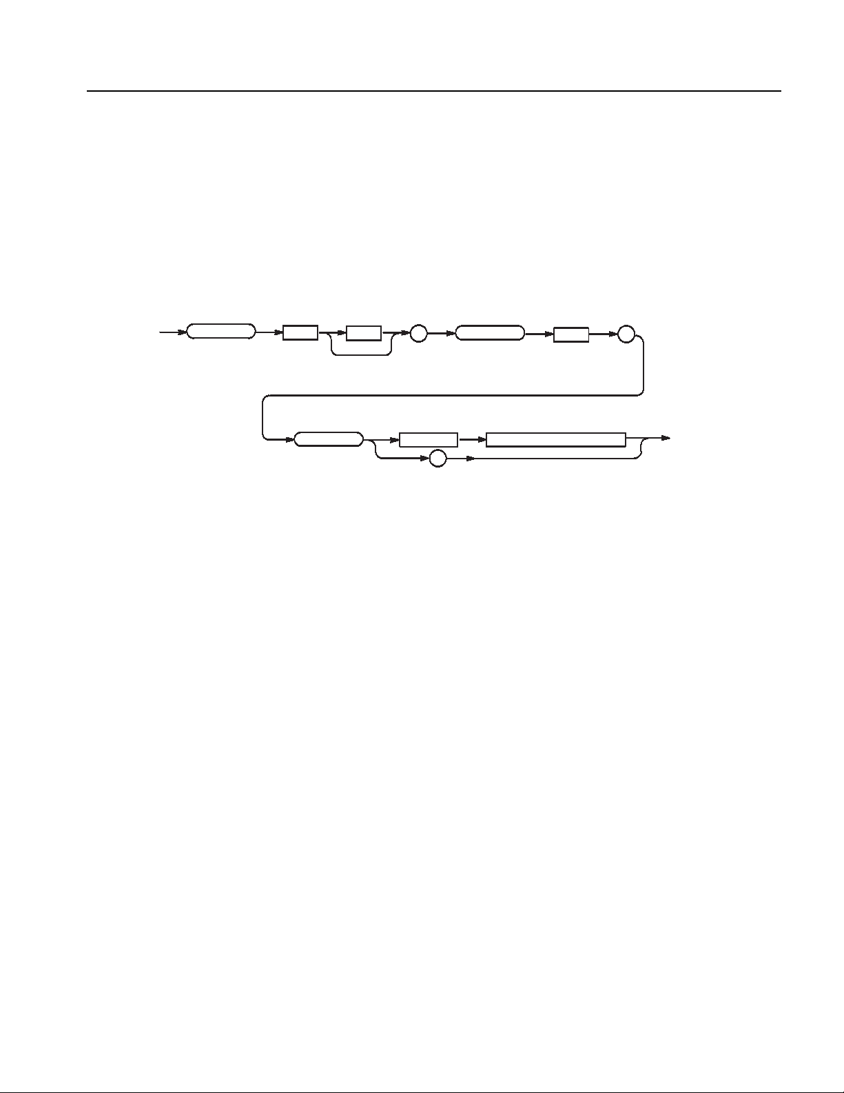
PGEN<x>[<m>]:CH<n>:DTOFfset(?)
This command sets the differential timing offset of the data output for the
specified channel.
Command Descriptions
Syntax
PGEN
Arguments
PGEN<x>[<m>]:CH<n>:DTOFfset <Numeric>
PGEN<x>[<m>]:CH<n>:DTOFfset?
<x>
DTOFfset <space>
<m>
:
?
CH
<Numeric>
Range: -1 to 1 ns
Step:
DTG 5078: 1 ps
DTG 5274/DTG5334: 0.2 ps
*RST returns the setting to 0.0 s.
<n>
:
Returns
Examples
<NR3>
PGENB:CH2:DTOFfset 1ps
Sets 1 ps for the differential timing offset value of the data output of
Mainframe 1, Slot B, Channel 2.
DTG5000 Series Data Timing Generators Programmer Manual 2-53

Command Descriptions
PGEN<x>[<m>]:CH<n>:DTOFfset:STATe(?)
This command turns on or off the differential timing offset for the data output of
the specified channel.
Syntax
PGEN
Arguments
Returns
PGEN<x>[<m>]:CH<n>:DTOFfset:STATe { ON | OFF | <NRf> }
PGEN<x>[<m>]:CH<n>:DTOFfset:STATe?
<x>
<m>
:
:
STATe
CH
<space>
<n>
:
ON
OFF
<NRf>
?
OFF or <NRf> = 0 - Turns off the differential timing offset.
ON or <NRf> ≠ 0 - Turns on the differential timing offset.
*RST returns the setting to 0 (Off).
<NR1>
DTOFfset
Examples
PGENA:CH1:DTOFset:STATe ON
Turns on the differential timing offset of Mainframe 1, Slot A, Channel 1.
2-54 DTG5000 Series Data Timing Generators Programmer Manual

PGEN<x>[<m>]:CH<n>:HIGH(?)
This command sets the high level of the data output for the specified channel.
Command Descriptions
Syntax
PGEN
Arguments
PGEN<x>[<m>]:CH<n>:HIGH <Numeric>
PGEN<x>[<m>]:CH<n>:HIGH?
<x>
<m>
HIGH <space>
:
?
CH
<n>
<Numeric>
:
Step: 5 mV
For the setting range, refer to the reference manual (the calculation is complicated).
The range is difficult to calculate, please refer to the reference manual (Chapter 2
Reference: “Output Level” Section). You can query the minimum value and the
maximum value by the use of MIN/MAX command.
*RST returns the setting to 1.0 V.
Returns
Examples
<NR3>
PGENB:CH2:HIGH 1.05
Sets 1.05 V for the high level of the data output of Mainframe 1, Slot B,
Channel 2.
PGENB:CH2:HIGH? MAX
Query the maximum high level of the data output of Mainframe 1, Slot B,
Channel 2 at the current.
DTG5000 Series Data Timing Generators Programmer Manual 2-55

Command Descriptions
PGEN<x>[<m>]:CH<n>:HLIMit(?)
This command sets the high limit of the data output.
Syntax
PGEN
Arguments
PGEN<x>[<m>]:CH<n>:HLIMit <Numeric>
PGEN<x>[<m>]:CH<n>:HLIMit?
<x>
HLIMit <space>
<m>
:
?
CH
<n>
<Numeric>
:
Step: 5 mV
For the setting range, refer to the reference manual (the calculation is complicated).
The range is difficult to calculate, please refer to the reference manual (Chapter 2
Reference: “Output Level” Section). You can query the minimum value and the
maximum value by the use of MIN/MAX command.
*RST returns the setting to 1.0 V.
Returns
Examples
<NR3>
PGENB:CH2:HLIMit 1.05
Sets 1.05 V for the high limit of the data output of Mainframe 1, Slot B,
Channel 2.
PGENB:CH2:HLIMit? MAX
Query the maximum high limit of the data output of Mainframe 1, Slot B,
Channel 2 at the current.
2-56 DTG5000 Series Data Timing Generators Programmer Manual
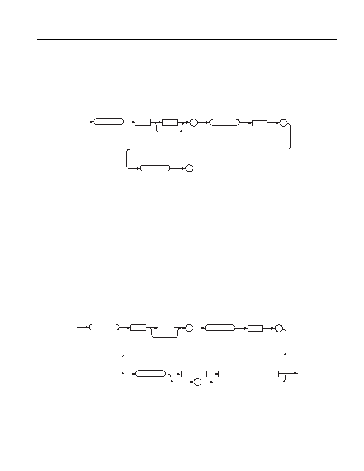
PGEN<x>[<m>]:CH<n>:IMPedance? (Query Only)
:
JRANge
pace>
umer
ic>
?
PGENN
CH
<n>
<x>
<m>
:
This command examines an output impidance of the DTGM21.
Command Descriptions
Syntax
PGEN
Returns
Examples
PGEN<x>[<m>]:CH<n>:IMPedance?
<x>
IMPedance
<NR3>
PGENA2:CH1:IMPedance?
Examines the current impedance setting of the data output of Mainframe 2, Slot A,
Channel 1.
If it is set to 50 ohm, the following will be returned: 50.0
PGEN<x>[<m>]:CH<n>:JRANge?
<m>
:
?
CH
<n>
:
Syntax
PGE
Arguments
This command sets a jitter range of the DTGM32.
PGEN<x>[<m>]:CH<n>:JRANge <numeric>
PGEN<x>[<m>]:CH<n>:JRANge?
<x>
<m>
JRANge
:
<s<space>
?
CH
Range: 1e-9 or 2e-9
*RST returns the setting to 2e-9.
<n>
<N<Numer
:
ic>
DTG5000 Series Data Timing Generators Programmer Manual 2-57
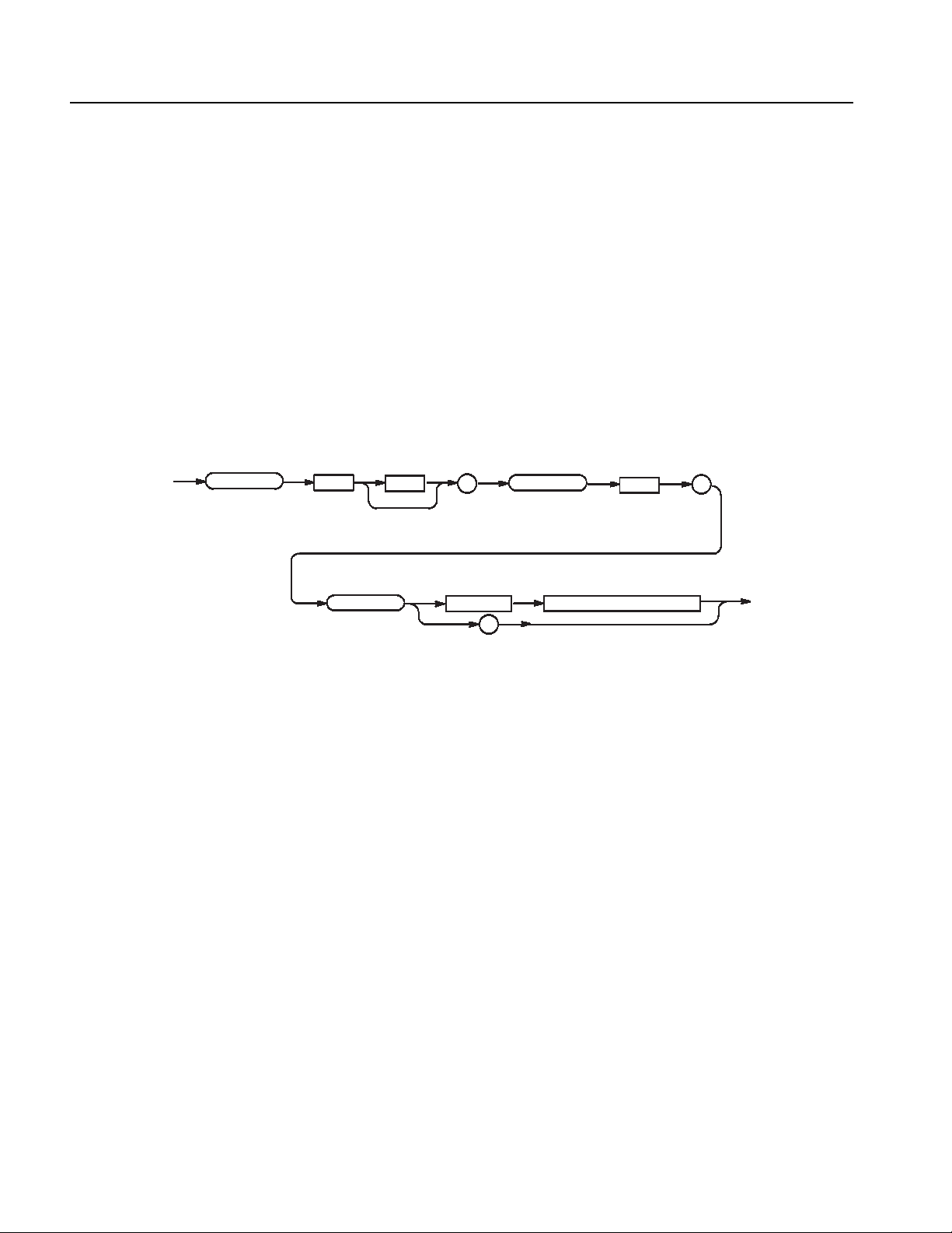
Command Descriptions
Returns
Examples
<NR3>
PGENA2:CH1:JRANge 1ns
Sets 1 ns for the jitter range of the data output of Mainframe 2, Slot A, Channel 1.
PGEN<x>[<m>]:CH<n>:LDELay(?)
This command sets the lead delay of the data output for the specified channel.
Syntax
PGEN
PGEN<x>[<m>]:CH<n>:LDELay <Numeric>
PGEN<x>[<m>]:CH<n>:LDELay?
<x>
LDELay <space>
<m>
:
?
CH
<n>
<Numeric>
:
Arguments
Returns
Examples
Step:
DTG 5078: 1 ps
DTG 5274/DTG5334: 0.2 ps
For the setting range, refer to the reference manual (the calculation is complicated).
The range is difficult to calculate, please refer to the reference manual (Chapter 2
Reference: “Timing Parameters” Section). You can query the minimum value and
the maximum value by the use of MIN/MAX command.
*RST returns the setting to 0.0 s.
<NR3>
PGENB:CH2:LDELay 1ps
Sets 1 ps for the lead delay of the data output of Mainframe 1, Slot B, Channel 2.
PGENB:CH2:LDELay? MAX
Query the maximum lead delay of the data output of Mainframe 1, Slot B,
Channel 2 at the current.
2-58 DTG5000 Series Data Timing Generators Programmer Manual
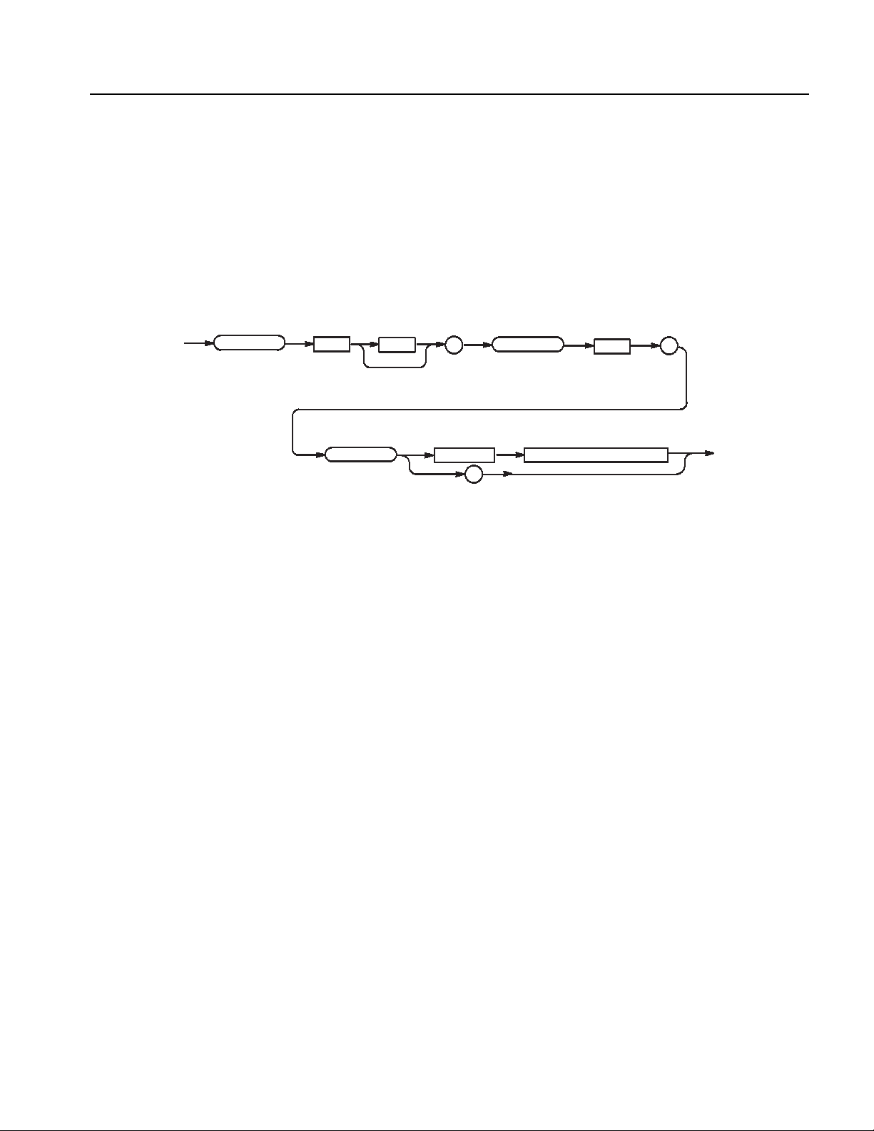
PGEN<x>[<m>]:CH<n>:LHOLd(?)
This command specifies how to hold the leading edge of the data output for the
specified channel.
Command Descriptions
Syntax
PGEN
Arguments
PGEN<x>[<m>]:CH<n>:LHOLd <lead_hold>
PGEN<x>[<m>]:CH<n>:LHOLd?
<x>
LHOLd <space>
<m>
:
?
CH
<lead_hold> ::= { LDELay | PHASe }
LDELay: Lead delay
PHASe: Phase
Note: Phase = lead delay / period x 100 (%)
*RST returns the setting to LDELay.
<n>
<lead_hold>
:
Returns
Examples
<lead_hold>
PGENA:CH1:LHOLd PHAse
Sets phase for how to hold the leading edge of the data output of Mainframe 1,
Slot A, Channel 1.
DTG5000 Series Data Timing Generators Programmer Manual 2-59

Command Descriptions
PGEN<x>[<m>]:CH<n>:LIMit(?)
This command sets whether the limit for the specified channel is applied.
Syntax
PGEN
Arguments
Returns
PGEN<x>[<m>]:CH<n>:LIMit { ON | OFF | <NRf> }
PGEN<x>[<m>]:CH<n>:LIMit?
<x>
<m>
:
CH
<n>
<space>
OFF or <NRf> = 0 - Turns off the limit.
ON or <NRf>
≠ 0 - Turns on the limit.
*RST returns the setting to 0.
<NR1>
?
:
<NRf>
LIMit
ON
OFF
Examples
PGENA:CH1:LIMit ON
Applies the limit to Mainframe 1, Slot A, Channel 1.
2-60 DTG5000 Series Data Timing Generators Programmer Manual

PGEN<x>[<m>]:CH<n>:LLIMit(?)
This command sets the low limit of the data output level for the specified
channel.
Command Descriptions
Syntax
PGEN
Arguments
PGEN<x>[<m>]:CH<n>:LLIMit <Numeric>
PGEN<x>[<m>]:CH<n>:LLIMit?
<x>
LLIMit <space>
<m>
:
?
CH
<n>
<Numeric>
:
Step: 5 mV
For the setting range, refer to the reference manual (the calculation is complicated).
The range is difficult to calculate, please refer to the reference manual (Chapter 2
Reference: “Output Level” Section). You can query the minimum value and the
maximum value by the use of MIN/MAX command.
*RST returns the setting to 0.0 V.
Returns
Examples
<NR3>
PGENB:CH2:LLIMit? MAX
Query the maximum low limit of the data output of Mainframe 1, Slot B,
Channel 2 at the current.
DTG5000 Series Data Timing Generators Programmer Manual 2-61

Command Descriptions
PGEN<x>[<m>]:CH<n>:LOW(?)
This command specifies the low level of the data output for the specified
channel.
Syntax
PGEN
Arguments
PGEN<x>[<m>]:CH<n>:LOW <Numeric>
PGEN<x>[<m>]:CH<n>:LOW?
<x>
<m>
LOW <space>
:
?
CH
<n>
<Numeric>
:
Step: 5 mV
For the setting range, refer to the reference manual (the calculation is complicated).
The range is difficult to calculate, please refer to the reference manual (Chapter 2
Reference: “Output Level” Section). You can query the minimum value and the
maximum value by the use of MIN/MAX command.
*RST returns the setting to 0.0 V.
Returns
Examples
<NR3>
PGENB:CH2:LOW MIN
Set the minimum low level of the data output of Mainframe 1, Slot B, Channel 2
at the current.
2-62 DTG5000 Series Data Timing Generators Programmer Manual

PGEN<x>[<m>]:CH<n>:OFFSet(?)
This command sets the offset level of the data output for the specified channel.
Command Descriptions
Syntax
PGEN
Arguments
PGEN<x>[<m>]:CH<n>:OFFSet <Numeric>
PGEN<x>[<m>]:CH<n>:OFFSet?
<x>
OFFSet <space>
<m>
:
?
CH
<n>
<Numeric>
:
Step: 5 mV
For the setting range, refer to the reference manual (the calculation is complicated).
The range is difficult to calculate, please refer to the reference manual (Chapter 2
Reference: “Output Level” Section). You can query the minimum value and the
maximum value by the use of MIN/MAX command.
*RST returns the setting to 0.5 V.
Returns
Examples
<NR3>
PGENB:CH2:OFFSet 0.6
Sets 0.6 V for the offset level of the data output of Mainframe 1, Slot B,
Channel 2.
PGENB:CH2:OFFSet? MAX
Query the maximum offset level of the data output of Mainframe 1, Slot B,
Channel 2 at the current.
DTG5000 Series Data Timing Generators Programmer Manual 2-63

Command Descriptions
PGEN<x>[<m>]:CH<n>:OUTPut(?)
This command turns on or off the data output of the specified channel.
Syntax
PGEN
Arguments
Returns
PGEN<x>[<m>]:CH<n>:OUTPut { ON | OFF | <NRf> }
PGEN<x>[<m>]:CH<n>:OUTPut?
<x>
<m>
:
CH
<n>
<space>
OFF or <NRf> = 0 - Turns off the data output.
ON or <NRf>
≠ 0 - Turns on the data output.
*RST returns the setting to 0.
<NR1>
?
:
<NRf>
OUTPut
ON
OFF
Examples
PGENA:CH1:OUTPut ON
Sets ON the data output for Mainframe 1, Slot A, Channel 1.
2-64 DTG5000 Series Data Timing Generators Programmer Manual

PGEN<x>[<m>]:CH<n>:PHASe(?)
This command sets the phase for the data output of the specified channel.
Command Descriptions
Syntax
PGEN
Arguments
PGEN<x>[<m>]:CH<n>:PHASe <Numeric>
PGEN<x>[<m>]:CH<n>:PHASe?
<x>
PHASe <space>
<m>
:
?
CH
<n>
<Numeric>
:
Both the lead delay and phase indicate the position of a pulse leading edge. They
differ only in the manner of representation, and is identical in the “substantial”
range of setting.
Step: 0.1%
For the setting range, refer to the reference manual (the calculation is complicated).
The range is difficult to calculate, please refer to the reference manual (Chapter 2
Reference: “Timing Parameters” Section). You can query the minimum value and
the maximum value by the use of MIN/MAX command.
*RST returns the setting to 0.0 %.
Set LHOLd to PHASe when setting PHASe.
Returns
Examples
<NR3>
PGENB:CH2:PHASe 1
Sets 1% for the phase for the data output of Mainframe 1, Slot B, Channel 2.
PGENB:CH2:PHASe? MAX
Query the maximum phase for the data output of Mainframe 1, Slot B,
Channel 2 at the current.
DTG5000 Series Data Timing Generators Programmer Manual 2-65

Command Descriptions
PGEN<x>[<m>]:CH<n>:POLarity(?)
This command sets the polarity of the data output for the specified channel.
Syntax
PGEN
Arguments
Returns
PGEN<x>[<m>]:CH<n>:POLarity <polarity>
PGEN<x>[<m>]:CH<n>:POLarity?
<x>
POLarity <space>
<m>
:
?
CH
<polarity>
<polarity> ::= { NORMal | INVert }
NORMal : Sets the polarity to positive.
INVert : Sets the polarity to negative.
*RST returns the setting to NORMal.
<polarity>
<n>
:
Examples
PGENA:CH1:POLarity INVert
Sets the polarity of data output to negative for Mainframe 1, Slot A, Channel 1.
2-66 DTG5000 Series Data Timing Generators Programmer Manual
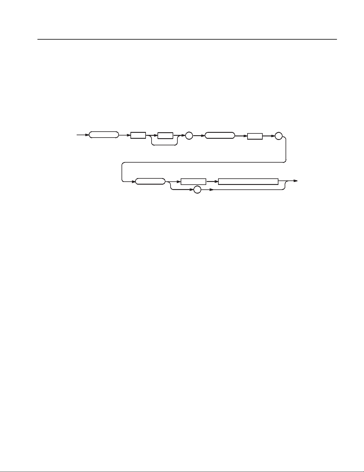
PGEN<x>[<m>]:CH<n>:PRATe(?)
This command sets the pulse rate of the specified channel.
Command Descriptions
Syntax
PGEN
Arguments
PGEN<x>[<m>]:CH<n>:PRATe <pulse_rate>
PGEN<x>[<m>]:CH<n>:PRATe?
<x>
PRATe <space>
<m>
:
?
CH
<n>
<pulse_rate>
:
<pulse_rate> ::= { NORMal | HALF | QUARter | EIGHth | SIXTeenth |
OFF }
NORMal : Sets the pulse rate to normal.
HALF : Sets the pulse rate to 1/2.
QUARter : Sets the pulse rate to 1/4.
EIGHth : Sets the pulse rate to 1/8.
SIXTeenth : Sets the pulse rate to 1/16.
OFF : Turns off the pulse rate.
*RST returns the setting to NORMal.
Returns
Examples
<pulse_rate>
PGENA:CH1:PRATe HALF
Sets the pulse rate for Mainframe 1, Slot A, Channel 1 to 1/2.
DTG5000 Series Data Timing Generators Programmer Manual 2-67
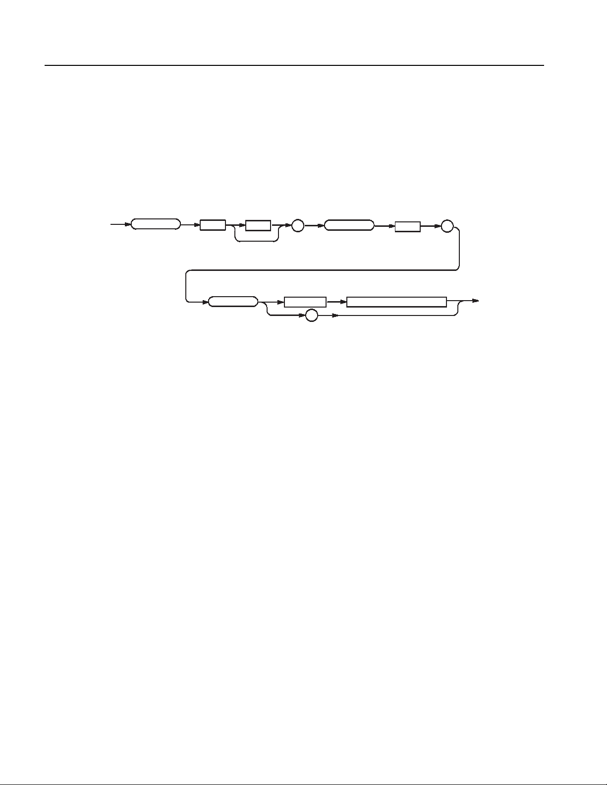
Command Descriptions
PGEN<x>[<m>]:CH<n>:SLEW(?)
This command sets the slew rate of the data output for the specified channel.
Syntax
PGEN
Arguments
PGEN<x>[<m>]:CH<n>:SLEW <Numeric>
PGEN<x>[<m>]:CH<n>:SLEW?
<x>
<m>
SLEW <space>
:
?
CH
<n>
<Numeric>
:
Step: 0.1 V/ns
For the setting range, refer to the reference manual (the calculation is complicated).
The range is difficult to calculate, please refer to the reference manual (Chapter 2
Reference: “Timing Parameters” Section). You can query the minimum value and
the maximum value by the use of MIN/MAX command.
*RST returns the setting to 2.25 V/ns.
Returns
Examples
<NR3>
PGENA:CH1:SLEW 5.1
Sets the slew rate for Mainframe 1, Slot A, Channel 1 to 5.1 V/ns.
2-68 DTG5000 Series Data Timing Generators Programmer Manual

PGEN<x>[<m>]:CH<n>:TDELay(?)
This command sets the trail delay of the data output for the specified channel.
Command Descriptions
Syntax
PGEN
Arguments
PGEN<x>[<m>]:CH<n>:TDELay <Numeric>
PGEN<x>[<m>]:CH<n>:TDELay?
<x>
TDELay <space>
<m>
:
?
CH
<n>
<Numeric>
:
Step: 5 ps
For the setting range, refer to the reference manual (the calculation is complicated).
The range is difficult to calculate, please refer to the reference manual (Chapter 2
Reference: “Timing Parameters” Section). You can query the minimum value and
the maximum value by the use of MIN/MAX command.
*RST returns the setting to 5e-9 s.
Set THOLd to TDELay when setting TDELay.
Returns
Examples
<NR3>
PGENA:CH1:TDELay 0.5ns
Sets 0.5ns for the trail delay of the data output of Mainframe 1, Slot A,
Channel 1.
PGENA:CH1:TDELay? MAX
Query the maximum trail delay of the data output of Mainframe 1, Slot A,
Channel 1 at the current.
DTG5000 Series Data Timing Generators Programmer Manual 2-69
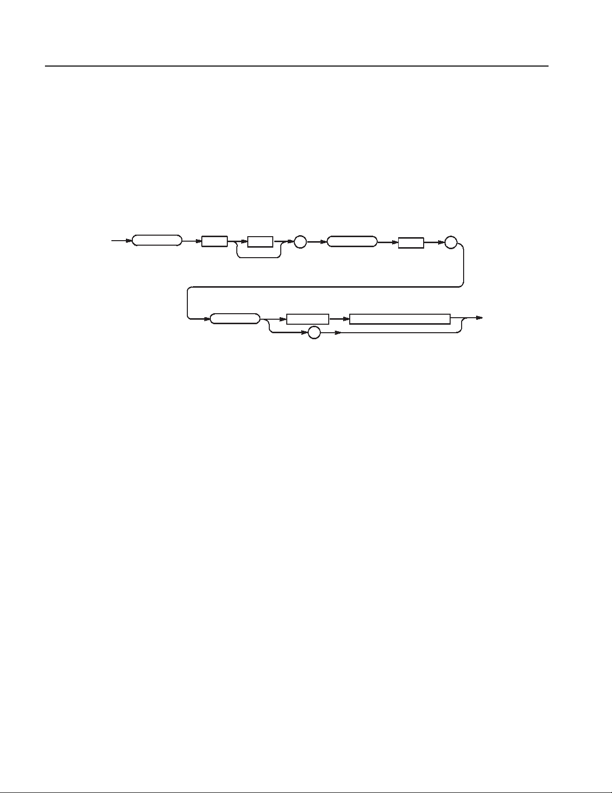
Command Descriptions
PGEN<x>[<m>]:CH<n>:THOLd(?)
This command specifies how to hold the trailing edge of the data output for the
specified channel.
Syntax
PGEN
Arguments
PGEN<x>[<m>]:CH<n>:THOLd <trail_hold>
PGEN<x>[<m>]:CH<n>:THOLd?
<x>
THOLd <space>
<m>
:
?
CH
<n>
<Numeric>
:
<trail_hold> ::= {TDELay | DCYCle | WIDTh}
TDELay: Sets TDELay for how to hold the trailing edge.
DCYCle: Sets DCYCle for how to hold the trailing edge.
WIDTh: Sets WIDTh for how to hold the trailing edge.
For the setting range, refer to the reference manual (the calculation is complicated).
The range is difficult to calculate, please refer to the reference manual (Chapter 2
Reference: “Timing Parameters” Section). You can query the minimum value and
the maximum value by the use of MIN/MAX command.
*RST returns the setting to DCYCle.
Returns
Examples
<trail_hold>
PGENA:CH1:THOLd TDELay
Sets TDELay for how to hold the trailing edge for Mainframe 1, Slot A,
Channel 1.
2-70 DTG5000 Series Data Timing Generators Programmer Manual

PGEN<x>[<m>]:CH<n>:TIMPedance(?)
This command sets the termination impedance of the data output for the
specified channel.
Command Descriptions
Syntax
PGEN
Arguments
PGEN<x>[<m>]:CH<n>:TIMPedance <Numeric>
PGEN<x>[<m>]:CH<n>:TIMPedance?
<x>
TIMPedance <space>
<m>
:
?
CH
<n>
<Numeric>
Range: 10 ohm to 1 Mohm,
≤ 0: Open
For Open, the response -1 will be returned.
Step: 3 significant digits. The minimum resolution is 1 ohm.
*RST returns the setting to 50 ohm.
:
Returns
Examples
<NR3>
PGENA:CH1:TIMPedance -1
Sets the termination impedance for Mainframe 1, Slot A, Channel 1 to Open.
DTG5000 Series Data Timing Generators Programmer Manual 2-71

Command Descriptions
PGEN<x>[<m>]:CH<n>:TVOLtage(?)
This command sets the termination voltage of the data output for the specified
channel.
Syntax
PGEN
Arguments
Returns
PGEN<x>[<m>]:CH<n>:TVOLtage <Numeric>
PGEN<x>[<m>]:CH<n>:TVOLtage?
<x>
TVOLtage <space>
<m>
:
?
CH
Range: -2 to +5V
Step: 0.1 V
*RST returns the setting to 0.0 V.
<NR3>
<n>
<Numeric>
:
Examples
PGENA:CH1:TVOLtage 1
Sets the termination voltage for Mainframe 1, Slot A, Channel 1 to 1 V.
2-72 DTG5000 Series Data Timing Generators Programmer Manual

PGEN<x>[<m>]:CH<n>:TYPE(?)
This command sets the format of data output for the channel specified in DG mode.
Command Descriptions
Syntax
PGEN
Arguments
Returns
PGEN<x>[<m>]:CH<n>:TYPE <data_format>
PGEN<x>[<m>]:CH<n>:TYPE?
<x>
<m>
TYPE <space>
:
?
CH
<data_format>
<data_format> ::= {NRZ | RZ | R1}
NRZ : Sets the signal to “NRZ format”.
RZ : Sets the signal to “RZ format”.
R1 : Sets the signal to “R1 format”.
*RST returns the setting to NRZ.
<data_format>
<n>
:
Examples
PGENA:CH1:TYPE R1
In DG mode, sets the format for Mainframe 1, Slot A, Channel 1 to
“Return to 1”.
DTG5000 Series Data Timing Generators Programmer Manual 2-73

Command Descriptions
PGEN<x>[<m>]:CH<n>:WIDTh(?)
This command sets the pulse width for the data output for the specified channel.
Syntax
PGEN
Arguments
PGEN<x>[<m>]:CH<n>:WIDTh <Numeric>
PGEN<x>[<m>]:CH<n>:WIDTh?
<x>
WIDTh <space>
<m>
:
?
CH
<n>
<Numeric>
:
Step: 5 ps
Can be obtained using the following conversion expression from the range of trail
delay or duty.
Pulse width = duty x (period x pulse rate) / 100
Or
Pulse width = trail delay - lead delay
*RST returns the setting to 5e-9 s.
Set THOLd to WIDTh when setting WIDTh.
Returns
Examples
<NR3>
PGENA:CH1:WIDTh 6e-9
Sets 6e-9 for the pulse width for Mainframe 1, Slot A, Channel 1.
2-74 DTG5000 Series Data Timing Generators Programmer Manual
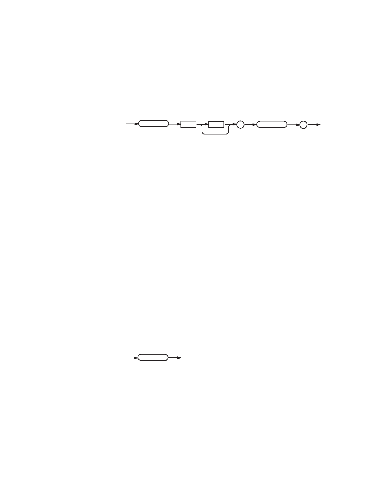
PGEN<x>[<m>]:ID? (Query Only)
*RSTT
This command examines what module the specified slot contains.
Command Descriptions
Syntax
Arguments
Returns
Examples
PGEN<x>[<m>]:ID?
PGEN
<x>
<m>
:
ID
None
<opt>
-1: No module
1: DTGM10
2: DTGM20
3: DTGM30
4: DTGM21
5: DTGM31
6: DTGM32
PGENB:ID?
Examines the module contained in Mainframe 1, Slot B.
If no module is contained, the following will be returned: -1
?
*RST (No Query Form)
This command resets the data timing generator to the default state. This command
has no effect on the network and communication settings, such as GPIB or IP
address. Refer to Appendix C: Factory Initialization Settings.
Syntax
Arguments
Examples
DTG5000 Series Data Timing Generators Programmer Manual 2-75
*RST
*RS
None
*RST
resets the instrument.

Command Descriptions
SEQuence:DATA(?)
This command sets the data corresponding to one line of a sequence.
SEQuence
Syntax
<space>
,
SEQuence:DATA <line_number>, <label>, <wait_trigger>,
<block/subsequence_name>, <repeat_count>, <jump_to>, <go_to>
SEQuence:DATA? <line_number>
:
?
DATA
<line_number>
<blobk/subsequence_name>
,
<go_to>
<space>
,
<line_number>
<label>
,
<repeat_count>
,
<wait_trigger>
,
<jump_to>
Arguments
<line_number> ::= <NR1> - Begins at 0.
<label> ::= <string> - 16 characters or less
<wait_trigger> ::= { ON | OFF | <NRf> }
<block/subsequence_name> ::= <string> - 32 characters or less
<repeat_count> ::= <NR1> - 1 to 65536
Zero (0) causes an endless loop.
<jump_to> ::= <string> - Destination to which control jumps when an event
occurs during output of this line.
<go_to> ::= <string> - Destination to which control jumps unconditionally after
output of this line.
The response following *RST:
"", 0, "Block1", 0, "", "".
2-76 DTG5000 Series Data Timing Generators Programmer Manual

Command Descriptions
Returns
Examples
SEQuence:LENGth(?)
Syntax
SEQuence
Arguments
<label>, <wait_trigger>, <block/subsequence_name>, <repeat_count>,
<jump_to>, <go_to>
SEQuence:DATA 0, "", OFF, "", 1, "", "Label2"
Indicates the following: line number 0, label “”, weight trigger Off, block name
“”, number of repetitions 1, destination of jump “”, and goto “Label2”.
This command changes the sequence length.
SEQuence:LENGth <NR1>
SEQuence:LENGth?
:
LENGth <space>
?
<NR1>
Range: 0 to 8000
When the length is increase, the content is indefinite.
Returns
Examples
*RST returns the setting to -1.
<NR1>
SEQuence:LENGth 1000
Sets the sequence length to 1000 lines.
DTG5000 Series Data Timing Generators Programmer Manual 2-77

Command Descriptions
SIGNal:ASSign(?)
This command assigns a physical channel to a logical channel.
SIGNa l
Syntax
:
Arguments
SIGNal:ASSign <logical_channel>, <physical_channel>
SIGNal:ASSign? <logical_channel>
ASSi gn <space>
?
<logical_channel>
<space>
<logical_channel>
,
<phys
ical_channel>
<logical_channel>:
<group_name> For a group with a 1-bit width
<group_name>[<bit>] Specified bit number in the specified group (This “[]”
can’t omit. )
Example:
CLK
Addr[0]
<physical_channel>
Use the mainframe number, slot name, and channel number to specify the
physical channel.
“1A4” indicates Mainframe 1, Slot A, Channel 4.
If you specify “”, the assignment will be reset.
*RST sets the auto-assignment.
Returns
Examples
<physical_channel>
SIGNal:ASSign "Addr[1]","1B4"
Assigns the physical channel of Mainframe 1, Slot B, Channel 4 to the logical
channel of group name Addr, bit number 1.
2-78 DTG5000 Series Data Timing Generators Programmer Manual

SIGNal:<parameter>(?)
Command Descriptions
This command sets various data output parameters using a signal name.
SIGNa l
Syntax
:
Arguments
SIGNal:<parameter> <signal>, <value>
SIGNal:<parameter>? <signal>
<par ameter >
<space>
?
<signal>
<space>
,
<signal>
<value>
<parameter> ::= {AMODe | AMPLitude | CPOint | DCYCle | DTOFfset |
DTOFfset:STATe | HIGH | HLIMit | LDELay | LHOLd | LIMit | LLIMit |
LOW | OFFSet | OUTPut | PHASe | POLarity | SLEW | TDELay | THOLd |
TIMPedance | TVOLtage | TYPE | WIDTh}
<signal> ::= logical channel or bus
For example:
Addr[]
Addr[0:3]
Addr[0..3]
Addr[3..0]
NOTE. If you omit the contents of the brackets, Addr[<msb>:<lsb>] will be
assumed. (For example, Addr is 8 bit wide, Addr[] will be assumed to be
Addr[7:0].)
<value> varies with <parameter>.
For more specific information, see the PGEN<x>[<m>]:CH<n> command
section.
If you query a number of channels, the first channel’s value will be returned.
For example, the SIGN:HIGH? "DATA[2..4]" command returns a value of
DATA[2].
Returns
Examples
<value>
SIGNal:AMPLitude "Addr[1]",1.1
Sets 1.1 V for the amplitude for the channel specified with Addr[1].
SIGNal:TYPE "Addr[2]",R1
Sets R1 for the format of the data output for the channel specified with Addr[2].
DTG5000 Series Data Timing Generators Programmer Manual 2-79

Command Descriptions
SIGNal:BDATa(?)
This command transfers pattern data in binary format.
SIGNal
Syntax
:
<space>
,
?
Arguments
SIGNal:BDATa <logical_channel>, <start_vector>, <vector_size>,
<binary_pattern_data>
SIGNal:BDATa? <logical_channel>, <start_vector>, <vector_size>
BDATa
<logical_channel>
<binary_pattern_data>
<space>
,
<logical_channel>
<start_vector>
,
<start_vector>
,
,
<vector_size>
<vector_size>
<logical_channel> ::= logical channel assigned with SIGNal:ASSign
<start_vector> ::= start address of data
<vector_size> ::= data size
<binary_pattern_data> ::= binary byte block
NOTE. Pattern data size is less than 1 MB (1024 x 1024).
Returns
Examples
<binary_pattern_data>
SIGNal:BDATa "Addr[1]",0,14,#12F9
This data contains the following:
#: Start character of the block
1: Indicates that the length in the length field is “1”.
2: Indicates that the length of the data is “2”.
F: 01000110
9: 00111001
2-80 DTG5000 Series Data Timing Generators Programmer Manual
 Loading...