


User Manual
DTG5078 & DTG5274
Data Timing Generators
071-1281-01
Volume 1 of 2
This document supports firmware version 1.0.14
and above.
www.tektronix.com

Copyright © Tektronix, Inc. All rights reserved.
Tektronix products are covered by U.S. and foreign patents, issued and pending. Information in this publication supercedes
that in all pre viously publish ed material. Specif ications and price change privileges reserved.
Tektronix, Inc., P.O. Box 500, Beaverton, OR 97077-0001
TEKTRONIX and TEK are registered trademarks of Tektronix, Inc.

WARRANTY
Tektronix warrants that the products that it manufactures and sells will be free from defects in materials and
workmanship for a period of one (1) year from the date of shipment. If this product proves defective during its
warranty period, Tektronix, at its option, will either repair the defective product without charge for parts and labor,
or provide a replacement in exchange for the defective product.
This warranty applies only to products returned to the designated Tektronix depot or the Tektronix authorized
representative from which the p roduct was originally purchased. For products returned to other locations,
Customer will be assessed an applicable service charge. The preceding limitation shall not apply within the
European Economic Area, where products may be returned for warranty service to the nearest designated service
depot regardless of the place of purchase.
In order to obtain service under this warranty, Customer must provide the applicable office of Tektronix or its
authorized representative with notice of the defect before the expiration of the warranty period and make suitable
arrangements for the performance of service. Customer shall be responsible for packaging and shipping the
defective product to the service center designated by Tektronix or its representative, with shipping charges
prepaid. Tektronix or its representative shall pay for the return of the product to Customer. Customer shall be
responsible for paying any associated taxes or duties.
This warranty shall not apply to any defect, failure or damage caused by improper use or improper or inadequate
maintenance and care. Tektronix shall not be obligated to furnish service under this warranty:
a) to repair damage resulting from attempts by personnel o ther than Tektronix representatives to install, repair or
service the product;
b) to repair dam age resulting from imp roper use or connection to incompatible equipment;
c) to repair any damage or malfunction caused by the use of non-Tektronix supplies or consumables;
d) to repair a product that has been modified or integrated with other products when the effect of such
modification or integration increases the time or difficulty of servicing the product; or
e) to repair damage or malfunction resu lting from f ailure to perf orm user maintenan c e and cleaning at the
frequency and as prescribed in the user manual (if applicable).
THE ABOVE WARRANTIES ARE GIVEN BY TEKTRONIX WITH RESPECT TO THIS PRODUCT IN LIEU OF
ANY OTHER WARRANTIES, EXPRESS OR IMPLIED. TEKTRONIX AND ITS VENDORS DISCLAIM ANY
IMPLIED WARRANTIES OF MERCHANTABILITY OR FITNESS FOR A PARTICULAR PURPOSE. TEKTRONIX’
RESPONSIBILITY TO REPAIR OR REPLACE DEFECTIVE PRODUCTS IS THE SOLE AND EXCLUSIVE
REMEDY PROVIDED TO THE CUSTOMER FOR BREACH OF THIS WARRANTY. TEKTRONIX AND ITS
VENDORS WILL NOT BE LIABLE FOR ANY INDIRECT, SPECIAL, INCIDENTAL, OR CONSEQUENTIAL
DAMAGES IRRESPECTIVE OF WHETHER TEKTRONIX OR THE VENDOR HAS ADVANCE NOTICE OF THE
POSSIBILITY OF SUCH DAMAGES.


Table of Contents
Getting Started
General Safety Summ ary v...................................
Preface vii...................................................
About This Manual vii...............................................
Related Manuals and Online Documents viii..............................
Contacting Tektronix ix.............................................
Product Description 1--1........................................
Models 1--1........................................................
Key Features 1--1....................................................
Mainframe and Output Module Configuration 1--3.........................
Product Software 1--3................................................
Software Upgrade 1--4................................................
Installation 1--5...............................................
Unpacking 1--5......................................................
Checking the Environment Requirements 1--6.............................
Output Module 1--7..................................................
Connecting to a Network 1--8..........................................
Connecting Peripherals 1--9............................................
Powering On the Data Timing Gener ator 1--1 0.............................
Setting up Windows 2000 1--11..........................................
Shutting Down the Data Timing Generator 1-- 12............................
Creating an Emergency Rescue Disk 1--14.................................
Backing Up User Files 1--16............................................
Installing Software 1--16...............................................
Accessories & Options 1--17......................................
Options 1--17........................................................
Accessories 1--19.....................................................
Operating Basics
Operating Basics 2--1..........................................
Front Panel Controls 2--1..............................................
Front Panel Connectors 2--5...........................................
Rear Panel Connectors 2--7............................................
Display Area and Application Windows 2--10..............................
Using the Menu System 2--37...........................................
Data Structure
Data Structure 3--1............................................
Internal Pattern Data 3 --1..............................................
Grouping and Channel Assignment 3--5..................................
DTG5078 & DTG5274 Data Timing Generator User Manual
i

Table of Contents
Tutorials
Index
List of Figures
Tutor i als 4- -1.................................................
Tutorial 1: Pulse Generator Mode 4--4...................................
Tutorial 2: Data Generator Mode 4--14....................................
Tutorial 3: Creating a Sequence 4--31.....................................
Figure 1--1: Locations of peripheral connectors on rear panel 1--9.....
Figure 1--2: Principal power switch and AC power connector 1--10.....
Figure 1--3: On/Standby switch location 1--10.......................
Figure 2--1: Front panel controls 2--2.............................
Figure 2--2: Front panel connectors 2--5...........................
Figure 2--3: Rear panel connectors 2--7............................
Figure 2--4: Screen elements just after the power on 2--10.............
Figure 2--5: Toolbar 2--15........................................
Figure 2--6: Status bar 2--16......................................
Figure 2--7: Channel Group window 2--17..........................
Figure 2--8: Blocks window 2--18..................................
Figure 2--9: Data-Listing window 2--20.............................
Figure 2--10: Data-Waveform window 2--22.........................
Figure 2--11: Level window 2--24..................................
Figure 2--12: Timing window (Data Generator mode) 2--26............
Figure 2--13: Time Base window 2--28..............................
Figure 2--14: Sequence window 2--30..............................
Figure 2--15: Subsequence window 2--32...........................
Figure 2--16: Jitter G eneration window 2--34........................
Figure 2--17: DC Output window 2--35.............................
Figure 2--18: Menu selection 2--37.................................
Figure 2--19: Window operation 1: Time Base window 2--38...........
Figure 2--20: Window operation 2: Timing window 2--39..............
Figure 2--21: Window operation 3: Data-Listing window 2--40.........
Figure 2--22: Window operation 4: Channel Group window 2--42......
Figure 2--23: Window operation 5: Sequence window 2--43............
ii
DTG5078 & DTG5274 Data Timing Generator User Manual

Table of Contents
Figure 3--1: Channels, groups, blocks and channel assignment 3--1....
Figure 3--2: Concept of data and window 3--4......................
Figure 3--3: Channel assignment 3--5.............................
Figure 3--4: Channel Group window 3--6..........................
Figure 4--1: Confirming Offline mode 4--1.........................
Figure 4--2: Select the online mode 4--2............................
Figure 4--3: Time Base window (Pulse Generator mode) 4--4..........
Figure 4--4: Level window (Pulse G enerator mode) 4--5..............
Figure 4--5: Timing window (Pulse Generator mode) 4--9............
Figure 4--6: Blocks window 4--14..................................
Figure 4--7: Channel Group window 4--15..........................
Figure 4--8: Data-Listing window 4--19.............................
Figure 4--9: Edit menu and View menu 4--19........................
Figure 4--10: View by Channel and View by Group 4--21..............
Figure 4--11: Timing window 4--28................................
Figure 4--12: SubBinary and SubWalking subsequences 4--33.........
Figure 4--13: Main sequence 4--36.................................
Figure 4--14: Flowchart 4--37.....................................
List of Tables
Table 1--1: DTG5000 series key features 1--2......................
Table 1--2: Operating requirements 1--7..........................
Table 1--3: Additional connection information 1--9.................
Table 1--4: Instrument options 1--17...............................
Table 1--5: Power cord options 1--17..............................
Table 1--6: Language options 1--18................................
Table 1--7: Standard accessories 1--19.............................
Table 1 --8: Optional accessories 1--20..............................
Table 2--1: Control box menus 2--11...............................
Table 2--2: File menus 2--11......................................
Table 2--3: View menus 2--12.....................................
Table 2--4: Settings menus 2--13..................................
DTG5078 & DTG5274 Data Timing Generator User Manual
iii

Table of Contents
Table 2--5: System menus 2--13...................................
Table 2--6: Options menu 2--14...................................
Table 2--7: Help me nus 2--14.....................................
Table 2--8: Status Bar 2--16......................................
Table 2--9: Edit menus for Channel Group window 2--17.............
Table 2--10: Setup items for Blocks window 2--19....................
Table 2--11: Edit menus for Blocks window 2--19....................
Table 2--12: Edit menus for Data-Listing window 2--21...............
Table 2--13: Edit menus for Data-Waveform window 2--22............
Table 2--14: Setup items for Level window 2--24.....................
Table 2--15: Edit menus for Level window 2--25.....................
Table 2--16: Setup items for Timing window 2--26...................
Table 2--17: Edit menus for Timing window 2--27...................
Table2--18:SetupitemsforTimeBasewindow 2--28................
Table 2--19: Setup items for Sequence window 2--30.................
Table 2--20: Edit menus for Sequence window 2--31.................
Table 2--21: Setup items for Subsequence window 2--32..............
Table 2--22: Edit menus for Subsequence window 2--33..............
Table 2 --23: Setup items for Jitter Generation window 2--34..........
Table 2--24: Setup items for DC Output window 2--35................
Table 2--25: Edit menus for DC output window 2--36................
Table 2--26: Key operations 2--47.................................
Table 4--1: Main sequence 4--35..................................
iv
DTG5078 & DTG5274 Data Timing Generator User Manual

General Safety Summary
Review the following safety precautions to avoid injury and prevent damage to
this product or any products connected to it. To avoid potential hazards, use this
product only as specified.
Only qualified personnel should perform service procedures.
To Avoid Fire or
Personal Injury
Use Proper Power Cord. Use only the power cord specified for this product and
certified for the country of use.
Ground the Product. This product is grounded through the grounding conductor
of the power cord. To avoid electric shock, the grounding conductor must be
connected to earth ground. Before making connections to the input or output
terminals of the product, ensure that the product is properly grounded.
Observe All Terminal Ratings. To avoid fire or shock hazard, observe all ratings
and markings on the product. Consult the product manual for further ratings
information before making connections to the product.
The common terminal is at ground potential. Do not connect the common
terminal to elevated voltages.
Do not apply a potential to any terminal, including the common terminal, that
exceeds the maximum rating of that terminal.
Do Not Operate Without Covers. Do not operate this product with covers or panels
removed.
Avoid Exposed Circuitry. Do not touch exposed connections and components
when power is present.
Do Not Operate With Suspected Failures. If you suspect there is damage to this
product, have it inspected by qualified service personnel.
Do Not Operate in Wet/Damp Conditions.
Do Not Operate in an Explosive Atmosphere.
Keep Product Surfaces Clean and Dry.
Provide Proper Ventilation. Refer to the manual’s installation instructions for
details on installing the product so it has proper ventilation.
DTG5078 & DTG5274 Data Timing Generator User Manual
v

General Safety Summary
Symbols and Terms
Terms in this Manual. These terms may appear in this manual:
WARNING. Warning statements identify conditions or practices that could result
in injury or loss of life.
CAUTION. Caution statements identify conditions or practices that could result in
damage to this product or other property.
Terms on the Product. These terms may appear on the product:
DANGER indicates an injury hazard immediately accessible as you read the
marking.
WARNING indicates an injury hazard not immediately accessible as you read the
marking.
CAUTION indicates a hazard to property including the product.
Symbols on the Product. The following symbols may appear on the product:
WARNING
High Voltage
Protective Ground
(Earth) Terminal
CAUTION
Refer to Manual
Double
Insulated
vi
DTG5078 & DTG5274 Data Timing Generator User Manual

Preface
About This Manual
This is the user manual (volume 1) for the DTG5000 Series Data Timing Generator. It covers the following information:
H Describes the capabilities of the data timing generator, how to install it and
reinstall its software.
H Provides tutorials to familiarize the user with two basic operation modes.
The pulse generator mode and data generator mode.
H Lists standard and optional accessories and instrument options available for
the data timing generator.
This manual is composed of the following sections:
H The Getting Started shows you how to configure and install your data timing
generator and provides instrument options and accessories list.
H The Operating Basics describes the data timing generator instrument
controls including rear panel connectors. It also provides information on the
data timing generator screen elements.
H The Data Structure describes the concept of data timing generator pattern
data.
H The Tutorials provides simplified application examples, which show you
how to create/edit the pattern data.
DTG5078 & DTG5274 Data Timing Generator User Manual
vii

Preface
Related Manuals and Online Documents
This manual is part of a document set of standard-accessory manuals and online
documentation. This manual mainly focuses on installation, background, and
user information needed to use the product features. See the following list for
other documents supporting the data timing generator operation a nd service.
(Manual part numbers are listed i n Accessories & Options on page 1--17.)
Document name Description
DTG5000 Series Online Help An online help system, integrated with the User Interface application that ships with this
product. The help is preinstalled in the data timing generator.
DTG5000 Series User Manual, volume 2 A reference provides encyclopedia of topics that describe the data timing generator
interface and features, and gives background information on how to use them.
DTG5000 Series Programmer Manual Provides complete information on programming commands and remote control of the
instrument.
DTG5000 Series Technical Reference for
Performance Verification & Specifications
DTG5000 Series Service Manual Describes how to service the data timing generator to the module level. This optional
Describes how to verify the performance of the data timing generator and lists its
specifications.
manual must be ordered separately.
viii
DTG5078 & DTG5274 Data Timing Generator User Manual

Contacting Tektronix
Preface
Phone 1-800-833-9200*
Address Tektronix, Inc.
Department or name (if known)
14200 SW Karl Braun Drive
P.O. Box 500
Beaverton, OR 97077
USA
Web site www.tektronix.com
Sales support 1-800-833-9200, select option 1*
Service support 1-800-833-9200, select option 2*
Technical support Email: techsupport@tektronix.com
1-800-833-9200, select option 3*
6:00 a.m. -- 5:00 p.m. Pacific time
* This phone number is toll free in North America. After office hours, please leave a
voice mail message.
Outside North America, contact a Tektronix sales office or distributor; see the
Tektronix web site for a list of offices.
DTG5078 & DTG5274 Data Timing Generator User Manual
ix

Preface
x
DTG5078 & DTG5274 Data Timing Generator User Manual

Product Description
This section describes the DTG5000 Series Data Timing Generators and their
options. Following this description are two subsections:
H Installation shows you how to configure and install the data timing
generator, as well as how to reinstall the system software included with the
product.
H Accessories & Options lists the standard and optional accessories for this
product.
Models
This manual supports the following data timing generators:
H DTG5078 Data Timing Generator
H DTG5274 Data Timing Generator
The differences between the data timing generators will be called out when
necessary; otherwise, the material applies to all data timing generators. The word
“data timing generator” refers to both products.
Key Features
The DTG5000 Series Data Timing Generator is a high speed/multichannel signal
generator which creates a wide range of digital timing signals. The products are
designed to generate a data pattern for standard and nonstandard pulses necessary
for functional tests or characterization of legacy devices (TTL, CMOS, ECL) as
well as the latest devices (PECL, LVDS, GTL, CML).
The DTG5000 Series Data Timing Generator supports three types of output
modules (DTGM10, DTGM20, and DTGM30). Table 1--1 lists the key features
of the data timing generators.
DTG5078 & DTG5274 Data Timing Generator User Manual
1--1

Product Description
,
,
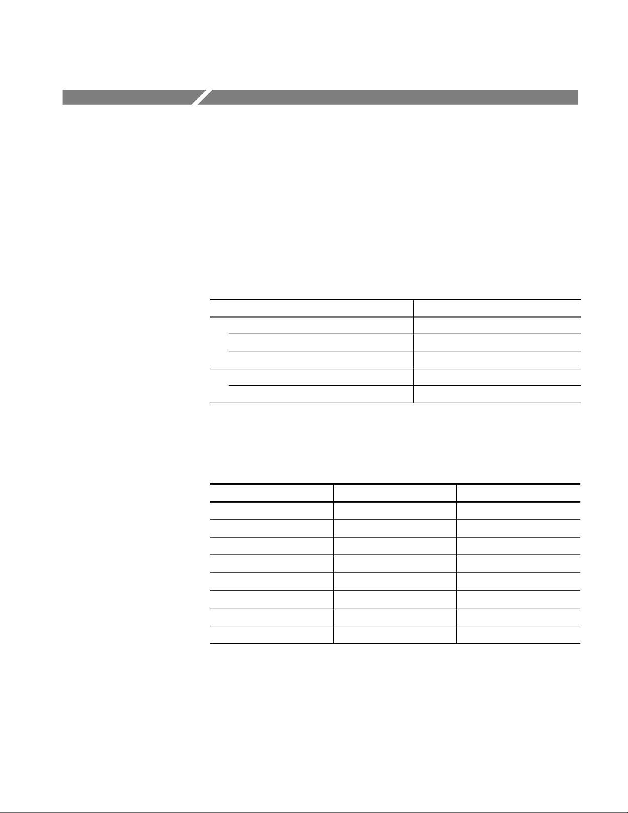
Table 1--1: DTG5000 series key features
DTG5078 DTG5274
Maximum clock
750 MHz/750 Mb/s 2.7GHz /2.7 Gb/s
frequency/ Maximum data rate
Number of slot 8 (A, B, C, D, E, F, G, and H) 4 (A, B, C, and D)
Pattern length 240 to 8,000,000 words/channel 960 to 32,000,000 words/channel
Block size
1 1 to 4 (depends on Vector Rate)
granularity
Sequence steps 1 to 8,000 steps 1 to 8,000 steps
Sequence
1 to 65,536 or Infinite 1 to 65,536 or Infinite
repeat counter
Data Generator
Slot A, B, C, D, E, F, G, and H Slot A, B, C, and D
Mode
Data format Slot A to D NRZ, RZ, and R1 Slot A to D NRZ, RZ, and R1
Slot E to H NRZ
Data rate NRZ 50 kb/s to 750 Mb/s NRZ 50 kb/s to 2.7 Gb/s
RZ and R1 50 kb/s to 375 Mb/s RZ and R1 50 kb/s to 1.35 Gb/s
Channel addition Slot A, B, C, and D Slot A, B, C, and D
Jitter generation Channel 1 of slot A Channel 1 of slot A
Lead delay
1ps 0.2 ps
resolution
Trail delay
5ps 5ps
resolution
Pulse width
5 ps (slot A, B, C, and D) 5 ps (slot A, B, C, and D)
resolution
Pulse Generator
Slot A, B, C, and D Slot A, B, C, and D
Mode
Clock frequency 50 kHz to 375 MHz 50kHzto1.35GHz
Output Module
Number of
channel
Amplitude (50 Ω) 3.5 V
Amplitude
DTGM10 DTGM20 DTGM30 DT GM 10 DTGM20 DTGM30
4 4 2 2of4
(CH1, CH2)
10 V
p-p
p-p
3.5 V
7V
p-p
p-p
1.25 V
2.5 V
p-p
p-p
3.5 V
10 V
p-p
p-p
2of4
(CH1, CH2)
3.5 V
p-p
7V
p-p
(1 MΩ)
Rise time/fall
time at 1 Vp-p
<540 ps
(variable)
<340 ps
(variable)
<110 ps <540 ps
(variable)
<340 ps
(variable)
into 50 Ω
(20% to 80%)
Master-Slave Up to three (one Master, two Slaves) Up to two (one Master, one Slave)
2
1.25 V
p-p
2.5 V
p-p
<110 ps
1--2
DTG5078 & DTG5274 Data Timing Generator User Manual

Mainframe and Output Module Configuration
The DTG5000 Series Data Timing Generator offers card modular system. Three
types of the output modules can be combined in any combination. Each module
can be inserted into any slot. The functional restrictions are:
H 8 (eight) slots installed in the DTG5078 (A, B, C, D, E, F, G, and H)
H 4 (four) slots installed in the DTG5274 (A, B, C, and D)
H When the DTGM10 or DTGM20 is installed to the DTG5274, CH3 and
CH4 are not available. Only CH1 and CH2 can be used.
H Slot E, F, G, and H are not available in the Pulse Generator mode.
H Available data formats are different:
H NRZ, RZ, R1 (Slot A, B, C, and D)
H NRZ (Slot E, F, G, and H)
Product Description
Product Software
The data timing generator includes the following software:
H The system software, which includes a specially configured version of
Windows 2000, comes preinstalled on the data timing generator. Windows 2000 is the operating system on which the user-interface application of
this product runs, and provides an open desktop for you to install other
compatible applications.
NOTE. Do not attempt to substitute any version of Windows that is not specifically provided by Tektronix for use with this instrument.
H The DTG5000 Software comes preinstalled on the data t iming generator.
This software, runs on Windows 2000, is the data timing generator application. This software starts automatically when the data timing generator is
powered on, and provides the user interface (UI) and all other instrument
control functions. You can also minimize the data timing generator application.
H The product software runs not only on the data timing generator
mainframe, but also on the general PC. When the software runs on the
data timing generator mainframe, it is called the Online mode. While
running on the PC, it is called the Offline mode. In the Offline mode, it
is possible to create and edit the pattern data and set the output parameters.
DTG5078 & DTG5274 Data Timing Generator User Manual
1--3

Product Description
H The DTG5000 Configuration Utility comes preinstalled on the data timing
generator. This software, running on Windows 2000, is used for setting up
the system configurat ions for the DTG5000 Software. This software controls
the Master operation, Master/Slave operation, Online/Offline operation, and
so forth.
NOTE. When you use the DTG5000 software with the offline mode, you must also
install the DTG5000 Configuration Utility into your PC.
H The Readme file contains release notes and updates that could not be
included in other product documentation.
H There are no limits on number of PCs that can operate in the offline mode.
Occasionally new versions of software for your instrument may become
available at our web site. See Contacting Tektronix on page ix in the Preface
section for web site information.
Software Upgrade
Tektronix may offer software upgrade kits for the data timing generator. Contact
your Tektronix service representative for more information (see Contacting
Tektronix on page ix).
1--4
DTG5078 & DTG5274 Data Timing Generator User Manual

Installation
This section covers installation of the data timing generator, addressing the
following topics:
H Unpacking on page 1--5
H Checking the Environment Requirements on page 1--6
H Output Module on page 1--7
H Connecting to a Network on page 1--8
H Connecting Peripherals on page 1--9
H Powering On the Data Timing Generator on page 1--10
H Setting up Windows 2000 on page 1--11
H Shutting Down the Data Timing Generator on page 1--12
H Creating an Emergency Rescue Disk on page 1--14
H Backing Up User Files on page 1--16
Unpacking
H Installing Software on page 1--16
CAUTION. Be sure to create your emergency rescue disk as described on
page 1--14. You may need that disk if you ever need to reinstall Windows 2000
from the data timing generator hard drive.
Verify that you have received all of the parts of your data timing generator. The
packing list shows the standard accessories that you should find in the shipping
carton. The output modules are not shipped within the mainframe carton. You
should also verify that you have:
H The correct power cord for your geographical area
H Two compact discs that include copies of the software installed on the data
timing generator and additional support software that may be useful to you.
Store the product software in a safe location where you can easily retrieve it.
H Recovery disk for Windows (R) 2000 Professional
DTG5078 & DTG5274 Data Timing Generator User Manual
1--5

Installation
H DTG5000 Series Product Software
NOTE. The certificate of authenticity (Windows 2000 licence agreement) is
attached to your data timing generator. This certificate proves your ownership of
the Windows operating system in your mainframe. Without this certificate, you
might have to purchase a new Windows license if the hard disk in your mainframe ever needs rebuilding or replacement.
H All the standard and optional accessories that you ordered
H Output module(s) you ordered
Remember to fill out and send in the customer registration card. The registration
card is packaged with this manual.
Checking the Environment Requirements
Read this section before attempting any installation procedures. This section
describes site considerations and power requirements for your data timing
generator.
Site Considerations
The data timing generator is designed to operate on a bench in the normal
position (on the bottom feet). For proper cooling, at least three inches (7.62 cm)
of clearance is required on both sides of the data timing generator, and the
bottom requires the clearance provided by the mainframe feet.
If you operate the data timing generator in the Master-Slave mode, you can stack
up to two mainframes.
CAUTION. To avoid damage to the mainframe, always close the bottom stands
when you stack the mainframes.
Using a cart is not recommended when you stack the mainframes. Doing so
could result in serious damage to the cart or mainframes.
Do not operate the mainframe while it rests on its left side feet. Always place the
mainframe in the normal position (on the bottom feet) while the mainframe
powered-on.
1--6
DTG5078 & DTG5274 Data Timing Generator User Manual

Installation
Operating Requirements
Output Module
Table 1--2 shows general operating requirements for the data timing generator.
For more information, refer to Technical Reference for Performance Verification
& Specifications. It covers power source, temperature, humidity and altitude
information.
Table 1--2: Operating requirements
Item Description
Operating temperature +10_Cto+40_C
Operating relative humidity 20% to 80% (No condensation)
Operating altitude Up to 3 km (10,000 ft)
Power supply
Rating voltage 100 V to 240 V
Voltage range 90 V to 250 V
Frequency 47 Hz to 63 Hz
Maximum power 600 VA maximum
Installing the Output
Module
The DTG5000 Series Data Timing Generator mainframe and output module(s)
are shipped separately. At least one output module must be installed in the
mainframe slot to operate properly.
Three types of output modules can be combined in any combination. Each
module can be inserted in any slot. There are functional differences between slot
A to D and slot E to H. (Refer to Mainframe and Output Configuration on page
1--3.) It is recommended that slot A should be used when only one output
module is installed in the mainframe slot.
To install the output module, first power off the mainframe using the front panel
On/Standby switch.
DTG5078 & DTG5274 Data Timing Generator User Manual
1--7

Installation
CAUTION. To prevent damage to the output module or mainframe, never install
or remove the output module when the mainframe is powered on.
Avoid touching the board surface or connectors of the output module with your
fingers when you handle the module.
Attach the blank panel to the mainframe module slot(s) when the output
module(s) are not installed.
If the output module is not in use for a long time, attach the connector caps and
SMA terminations (DTGM30) to the output module and then store the output
module in the shipping carton. The connector caps and SMA terminations are
provided with your output module.
1. Verify that the data timing generator mainframe is not powered on.
2. Remove the blank panel from the mainframe slot.
3. Place the output module in a compartment.
4. Gently push the output module into the slot with firm pressure.
5. Once the module is seated, tighten the two screws to secure the module to
Removing the Output
Module
Verify that the data timing generator mainframe is not powered on.
1. Loosen the two screws.
2. Grasp the right and left screws and slowly pull the module out of the
3. Attach a blank panel to the slot.
Connecting to a Network
You can connect the data timing generator to a network to enable printing, file
sharing, internet access, and other communications functions. In the MasterSlave mode, the slave mainframe is controlled by the Master-mainframe
connection between the mainframes. Before you use the Master-Slave mode,
connect each mainframe to a network. Refer to page 2--9 for more information
explaining Master-Slave connections. Also see Figure 2--3:Rear panel connections.
the mainframe.
mainframe slot.
1--8
Connect the network cable to the mainframes before power-on.
For more information on the Master-Slave operation, refer to DTG5000 Series
User Manual, volume 2.
DTG5078 & DTG5274 Data Timing Generator User Manual

Connecting Peripherals
Installation
The peripheral connections are the same as those you would make on a personal
computer. The connection points are shown in Figure 1--1. See Table 1--3 for
additional connection information.
CAUTION. To avoid product damage, power off the data timing generator or
place the data timing generator in Standby power mode before installing any
accessories except a USB mouse or a USB keyboard to the mainframe connectors. (You can connect or disconnect USB devices while powering on the
mainframe.) See Powering Off the Data Timing Generator on page 1--12.
LAN
VGA monitor
CD-ROM drive
USB
GPIB
COM
Mouse
Keyboard
Figure 1--1: Locations of peripheral connectors on rear panel
Table 1--3: Additional connection information
Item Description
Monitor If you use an external monitor with the data timing generator
mainframe screen, the resolution of the external monitor is
fixed to 800 x 600. If you select the external monitor only, high
resolution display can be possible. You can set the resolution
by using the Windows 2000 control panel.
Printer If you connect the printer directly to the data timing generator,
DTG5078 & DTG5274 Data Timing Generator User Manual
connect the USB printer to a USB connector port of the
mainframe. You cannot connect the parallel printer directly to
the mainframe. If your data timing generator is connected to
LAN, you can use a network printer.
1--9

Installation
Powering On the Data Timing Generator
Follow these steps to power on the data timing generator. Refer to page 1--11 for
Windows 2000 setup.
1. Connect the proper power cord from the rear panel power connector to the
power system.
Switch
AC power
connector
Figure 1--2: Principal power switch and AC power connector
NOTE. Connect the keyboard, mouse and other accessories before applying
power to the product.
2. Turn on the principal power switch at the rear panel. (See Figure 1--2 for
switch location.)
3. Push the front panel On/Standby switch to power on the data timing
generator (see Figure 1--3 for the switch location).
On/Standby
Switch
1--10
Figure 1--3: On/Standby switch location
DTG5078 & DTG5274 Data Timing Generator User Manual

Setting up Windows 2000
You need to set up the Windows 2000 when you first power on the data timing
generator.
NOTE. Connect the keyboard and mouse before powering on the mainframe when
you set up the Windows 2000.
1. Attach the standard accessory USB mouse and USB keyboard to the data
2. Push the front panel On/Standby switch to power on the mainframe.
3. The Windows 2000 setup wizard appears on the data timing generator
4. Follow the on-screen instructions.
Installation
timing generator mainframe. Three USB connector ports are equipped with
the mainframe (two on the rear panel and one on the front right side).
screen.
5. When Your Product Key dialog box appears, enter the bar code number
which is located at the rear panel of mainframe.
6. Click Next button to display Date and Time Settings dialog box.
7. Confirm that the Date and Time Settings information is correct, and the click
Next button.
8. A dialog box pops up to let you know that the Windows 2000 setup has been
completed.
9. Click Restart Now, and Windows runs.
The computer name is DTG5000, and you can log on the Windows 2000 as the
following user name and password.
H User name: Administrator
H Password: dtg5000
If you want to add the user name, or want to change the password, always use
the Control Panel -- > Users and Passwords. For more information, consult
Windows 2000 Help.
NOTE. If you connect a second or third DTG5000 Series Data Timing Generator
to the network, use different computer names for additional mainframes.
DTG5078 & DTG5274 Data Timing Generator User Manual
1--11

Installation
Shutting Down the Data Timing Generator
When you push the front-panel On/Standby switch, the data timing generator
starts a shutdown process (including a Windows shutdown) to preserve settings.
This action removes power from most circuitry in the data timing generator.
Avoid using the rear panel power switch or disconnecting the line cord to power
off the mainframe.
The DTG5000 Series Data Timing Generator runs on Windows 2000, the shut
down process is similar to a PC.
There are three ways to shut down the mainframe:
H Push the On/Standby switch
H Select the Windows Start menu, and then select Shut Down...
H Select the File menu from the DTG5000 software, then select Shutdown.
When the data timing generator settings were not changed. When the
DTG5000 software is not running, or if the data timing generator settings have
not changed since the mainframe start-up, the shut down process closes all the
programs on Windows then restores the settings. The power is automatically shut
off.
When the data timing generator settings were changed. If the DTG5000 Series
Data Timing Generator settings were changed after the mainframe start-up. The
dialog box shown below appears on the screen and asks if you want to save the
current settings. Push any button within five seconds.
H Select Yes to specify the file name and location, and then select OK to
continue the shut down process.
H Select No without saving the setup file and continue the shut down process.
H Select Cancel to abort shut down process and to return to the DTG5000 soft-
ware.
1--12
DTG5078 & DTG5274 Data Timing Generator User Manual

Installation
If you do not select the options within five seconds, Windows forces to terminate
the DTG5000 software. The End Program dialog appears.
H Select End Now to continue the shut down process without saving the setup
file.
Without any action in ten seconds, the following dialog box appears.
The DTG5000 software is waiting for the information about whether the user
wants to save the setup information. In this case, Windows cannot terminate the
DTG5000 software.
H Select End Now to continue the shut down process without saving the setup
file.
H Select Cancel to return to the DTG5000 software.
In all cases, select End Now to exit all the Windows programs while preserving
the current Windows setting. This shuts off the power to the mainframe.
To completely remove the power from the data timing generator, perform the
shutdown described above. Shut off the principal power switch at the rear panel,
and then disconnect the power cord from the mainframe.
DTG5078 & DTG5274 Data Timing Generator User Manual
1--13

Installation
NOTE. If you push the front panel On/Standby switch for more than four seconds,
the data timing generator power is forced to be shut off.
Do not attempt to push the rear panel principal power switch before shutting
down the mainframe properly.
Creating an Emergency Rescue Disk
Now that you have completed the basic installation process, you should create an
emergency rescue disk that you can use to restart your data timing generator in
case of a major hardware or software failure.
NOTE. Create the emergency rescue disk and store it in a safe place. It may allow
you to recover your Windows 2000 installation without rebuilding the entire data
timing generator hard disk.
The emergency rescue disk contains basic files to restart your data timing
generator. Follow these steps to create the emergency rescue disk:
1. Log on the mainframe with the administrator name. Refer to page 1--11.
2. Click the Windows Start button, select Program -- > Accessories -- > System
Tools -- > Backup. The following dialog box appears.
1--14
3. Insert a formatted floppy disk into the floppy disk drive, and then click
Emergency Repair Disk.
DTG5078 & DTG5274 Data Timing Generator User Manual

4. The Emergency Repair Diskette dialog box appears.
5. Click Also backup the registry..., and then click OK.
6. Wait until the task completes. The following dialog appears.
Installation
7. Click OK, then remove the floppy disk and store it at a safe place.
DTG5078 & DTG5274 Data Timing Generator User Manual
1--15

Installation
Backing Up User Files
You should always back up your user files on a regular basis. Use the Back Up
tool to back up files stored on the hard disk. The Back Up tool is located in the
System Tools folder in the Accessories folder.
1. Log on the mainframe with the administrator name. Refer to page 1--11.
2. Click the Windows Start button, select Program -- > Accessories -- > System
Tools -- > Backup.
3. Click Backup Wizard.
4. Follow the on-screen instructions.
5. The backup tool allows you to select your backup media and to select the
files and folders that you want to back up. Use the Windows online help for
information on using the Backup tool. You can back up to the floppy drive or
to a third-party storage device.
Installing Software
System Diagnostics
The data timing generator mainframe ships with the product software installed,
so only perform the reinstallation if it becomes necessary. For more information
on the software reinstallation, refer to the User Manual, volume 2.
In case of instrument problems, you may wish to run the system diagnostics. See
the related manual (Technical Reference for Performance Verification and
Specifications) for more information on self tests and system diagnostics.
1--16
DTG5078 & DTG5274 Data Timing Generator User Manual
Accessories & Options
This section lists the standard and optional accessories available for the
DTG5000 Series Data Timing Generator as well as the product options.
Options
The following instrument options can be ordered for the instrument.
Table 1--4: Instrument options
Option Description
Mainframe (DTG5078/DTG5274)
Option D1 Certificate with Calibration Data
Option 1R Rackmount kit
Output Module (DTGM10/DTGM20/DTGM30)
Option D1 Certificate with Calibration Data
Power Cord Options
The following power cord options are available for the instrument.
Table 1--5: Power cord options
Option Area Tektronix part number
A0 North America 161-0230--01
A1 Universal European 161-0104--06
A2 United Kingdom 161-0104--07
A3 Australian 161-0104--05
A5 Switzerland 161-0167--00
A6 Japan 161-A005--00
A10 China 161-0306--00
A99 No power cord -- -- --
DTG5078 & DTG5274 Data Timing Generator User Manual
1--17

Accessories & Options
Language Options
The following two language options are provided for the data timing generator
documents. You must specify a language option when you place an order.
Table 1--6: Language options
Option Descriptions Par t number
L0 English manuals
User Manual, volume 1 071-1281--xx
User Manual, volume 2 071-1282--xx
Programmer Manual 071-1283--xx
Technical Reference for Performance
Verification and Specifications
L5 Japanese manuals
User Manual, volume 1 071-1277--xx
User Manual, volume 2 071-1278--xx
Programmer Manual 071-1279--xx
Technical Reference for Performance
Verification and Specifications
1
This manual is provided in English only.
1
071-1280--xx
071-1280--xx
1--18
DTG5078 & DTG5274 Data Timing Generator User Manual

Accessories
SeeTable16for
Accessories & Options
This section lists the standard and optional accessories available for this data
timing generator.
Standard
The following accessories are shipped with the data timing generator:
Table 1--7: Standard accessories
Accessory Part number
Mainframe
User Manual, volume 1
User Manual, volume 2
Programmer Manual
Technical Reference for Performance Verification and Specifications
Windows 2000 Professional Operating System Recovery Disk 062-A300-xx
DTG5000 series Product Software 062-A301-xx
USB Keyboard 119-B146-00
USB Mouse 119-B145-00
Lead Set for DC Output 16-CON twisted pair, 60 cm (24 in) 012-A229-00
Front Cover 200-4651-00
Accessory Pouch 016-1441-00
50 Ω SMA Termination, Male, DC-18 GHz 015-1022-01
See Table 1--6 for
part number.
Ten SMA Connector Caps (DTG5078) 200-A531-00
Eight SMA Connector Caps (DTG5274) 200-A531-00
Output Module
Installation Manual 071-1284-xx
Notice Sheet 061-4261-xx
Four SMA Connector Caps (DTGM10 or DTGM20) 200-A531-00
Two SMA Connector Caps (DTGM30) 200-A531-00
Two 50 Ω SMA Terminations, Male, DC-18 GHz (DTGM30) 015-0706-00
DTG5078 & DTG5274 Data Timing Generator User Manual
1--19

Accessories & Options
Optional
The accessories in Table 1--8 can be ordered for use with the data timing
generator at the time this manual was originally published. Consult a current
Tektronix catalog for additions, changes, and details.
Table 1--8: Optional accessories
Accessory Part number
Service Manual 071-1285-xx
50 Ω SMA Cable set for 2 units Master-Slave Operation 012-A230-00
Four 51 cm SMA Cables (174-1427-00)
Two 46 cm BNC Cables (012-0076-00)
50 Ω SMA Cable set for 3 units Master-Slave Operation 012-A231-00
Six 51 cm SMA Cables (174-1427-00)
Three 46 cm BNC Cables (012-0076-00)
Transition Time Converter, 150 ps 015-0710-00
Transition Time Converter, 250 ps 015-0711-00
Transition Time Converter, 500 ps 015-0712-00
Transition Time Converter, 1000 ps 015-0713-00
Transition Time Converter, 2000 ps 015-0714-00
HDMI TPA-R Test Adapter set 013-A012-50
Two HDMI TPA-R TDR
HDMI TPA-R DI (differential)
HDMI TPA-R SE (single end)
HDMI TPA-P Test Adapter set 013-A013-50
HDMI TPA-P TDR
HDMI TPA-P DI (differential)
HDMI TPA-P SE (single end)
DVI TPA-R Test Adapter set 013-A014-50
Two DVI TPA-R TDR
DVI TPA-R DI (differential)
DVI TPA-R SE (single end)
GPIB cable (2 m, double-shielded) 012-0991-00
GPIB cable (1 m, double-shielded) 012-0991-01
Pin Header Cable (51 cm, 20 in) 012-1505-00
Pin Header SMB Cable (51 cm, 20 in) 012-1503-00
SMB-BNC Adapter 015-0671-00
50 Ω BNC Cable (46 cm, 18 in) 012-0076-00
50 Ω BNC Cable (61 cm, 24 in) 012-1342-00
1--20
DTG5078 & DTG5274 Data Timing Generator User Manual

Accessories & Options
Table 1--8: Optional accessories (cont.)
Accessory Part number
50 Ω BNC Cable (107 cm, 42 in) 012-0057-01
50 Ω BNC Cable (250 cm, 98 in) 012-1256-00
50 Ω SMA Cable (30 cm, 12 in) 174-1364-00
50 Ω SMA Cable (51 cm, 20 in) 174-1427-00
50 Ω SMA Cable (100 cm, 39 in) 174-1341-00
50 Ω SMA Cable (152 cm, 60 in) 174-1428-00
50 Ω Delay SMA Cable (1 ns, Male to Female) 015-1019-00
50 Ω Delay SMA Cable (2 ns, Male to Male) 015-0560-00
50 Ω Delay SMA Cable (2 ns, Male to Female) 015-1005-00
50 Ω Delay SMA Cable (5 ns, Male to Male) 015-0561-00
50 Ω Delay SMA Cable (5 ns, Male to Female) 015-1006-00
50 Ω SMA Male to BNC Female Adapter 015-0554-00
50 Ω SMA Female to BNC Male Adapter 015-0572-00
50 Ω SMA Male to N Male Adapter 015-0369-00
50 Ω SMA Male to SMA Female Adapter 015-0549-00
50 Ω SMA Female to SMA Slide On Male Adapter 015-0553-00
50 Ω SMA Male to SMA T (Female/Female) Connector 015-1016-00
50 Ω SMA Divider (Ma/Ma/Ma, 6 dB, DC to 18 GHz, VSWR: 1.9) 015-1014-00
50 Ω BNC DC Block (500 kHz to 2 GHz) 015-0221-00
DTG5078 & DTG5274 Data Timing Generator User Manual
1--21

Accessories & Options
1--22
DTG5078 & DTG5274 Data Timing Generator User Manual

Operating Basics
Front Panel Controls
This section contains information on the various interfaces for controlling the
DTG5000 Series Data Timing Generator and basic menu operation of the
instrument.
H The Front Panel Controls on page 2--1 provides a quick overview of front
panel controls such as the knob, buttons and keys.
H The Front Panel Connectors on page 2--5 subsection provides a quick
overview of front panel connectors.
H The Rear Panel Connectors on page 2--7 provides a quick overview of rear
panel connectors.
H The Display Area and Application Windows on page 2--10 describes the
overview of screen elements and the application windows.
H The Using the Menu System on page 2--37 provides an overview of the menu
and key operations of the data timing generator.
Navigation Keys
This section introduces you to the front panel controls of the data timing
generator, which provides a brief overview on how to use the front panel key
controls.
In addition to the front panel controls, you can also control the data timing
generator from a keyboard and a mouse (provided with the instrument).
The MENU and SELECT buttons, TAB, ESC, and the Up, Down, Left and
Right arrow keys are called navigation keys. These buttons and keys allow you
to perform the data timing generator basic windows operation without using a
mouse or a keyboard. Figures 2--1 shows the locations of the front-panel
controls.
MENU button. Pushing the MENU button opens the pull-down menu items of the
last menu bar that you opened, regardless of current selection.
To cancel the pull-down menu, push the MENU button again. Pressing the ESC
key also forces the pull-down menu to disappear, however the menu bar is still
active. If you press any arrow key in this state, the key operates on the menu bar
area. Pressing the ESC key twice moves the focus to the lower window area.
DTG5078 & DTG5274 Data Timing Generator User Manual
2--1

Operating Basics
SELECT button. The SELECT button has the same capability as the Windows
standard ENTER key. This button is mainly used for the following actions:
H Use to make a selection on the pull-down menu items
H Use to open a pop-up menu in a tabular view
H Use to select an item in a pop-up menu
H Use to select OK or Cancel in the dialog box
Navigation
keys
Digit Select
arrow keys
Figure 2--1: Front panel controls
TAB key. The TAB key is used to move the focus within the window. By pressing
the SHIFT and TAB keys simultaneously, you can move the focus in the reverse
direction.
ESC key. The ESC key is used to cancel text input or dialog box appearance. To
cancel the menu items opened with the MENU button, press the ESC key twice.
Arrow keys (Up, Down, Left and Right). The arrow keys are used for the following
actions:
2--2
H Use to open the pull-down menus on the menu bar and move to the desired
items, after pushing the MENU button (you can also use the knob).
H Use to move the current cell (cursor position) in a tabular view
DTG5078 & DTG5274 Data Timing Generator User Manual

Operating Basics
H Use to select a radio button
The arrow keys have the capability of auto repeat.
DATA, LEVEL and TIMING buttons. Provide direct access to frequently used menus.
H DATA button: The DATA button is used to display previously selected pattern
data editing window (Data-Listing window or Data-Waveform window).
While one window is displayed, pushing this button switches to the alternate
window on the screen.
H LEVEL button: The LEVEL button is used to display the Level window and
moves the focus to the previously selected items.
H TIMING button: The TIMING button is used to display the Timing window
and moves the focus to the Clock Frequency or previously selected item.
Knob. The knob is used to increment or decrement a set value or select an item
from a pop-up or pull-down menu. Use right or left arrow keys just under the
knob to move the digit when you increment or decrement the setup value.
Digit Select arrow keys. The Digit Select arrow key is used to move the underbar
to a field that contains an editable number. This will allow you to change the
digit with the knob.
RUN button. The RUN button is used to control the start and stop of signal
outputs.
If the signal is being output, the LED indicator lights up. To actually output the
signal through the output connectors, you must turn the Output on in the Level
window or push the front panel ALL OUTPUTS ON/OFF button.
PULSE GEN button. The PULSE GEN button is used to toggle between Pulse
Generator and Data Generator modes. The LED lights up when the instrument is
in PG mode.
MANUAL TRIGGER button. The MANUAL TRIGGER button is used to generate
an internal trigger.
MANUAL EVENT button. The MANUAL EVENT button is used to generate an
event signal internally.
Suffix buttons (p, G/n, M/,k/m).After you complete the input with numeric keys,
you can determine the unit by pushing one of the suffix buttons, without pressing
the Enter key.
If you push a suffix button for a frequency, the unit is interpreted as G (giga-), M
(mega-) or k (kilo-). If you push it for a time or voltage, the unit is interpreted as
p (pico-), n (nano-), (micro-) or m (milli-).
SHIFT key. The SHIFT key has the same capability as the Shift key on a
Windows PC keyboard.
DTG5078 & DTG5274 Data Timing Generator User Manual
2--3

Operating Basics
ALT key. The ALT key has the same capability as the Alt key on a Windows PC
keyboard.
CTRL key. The CTRL key has the same capability as the Ctrl key on a Windows
PC keyboard.
ALPHA key. The ALPHA key is used to enter a character with a numeric key.
Pressing the ALPHA key causes the LED to light up.
While the LED is on, the data timing generator is in the text input mode and you
can use numeric keys to enter alphanumeri c characters.
SPACE key. The SPACE key switches the On/Off state of a check box. Pressing
the ALT and SPACE keys simultaneously displays the Control menu. See DTG
icons on page 2--11 for details on the Control menu.
BKSP key. The BKSP key has the same capability as the Back Space key on a
Windows PC keyboard.
DEL key. The DEL key has the same capability as the Delete key on a Windows
PC keyboard.
ALL OUTPUTS ON/OFF button. This button is used to switch the on/off of channel
output, DC output or clock output. To turn on or off of these outputs, use the
Level window, DC Output window, or Time Base window, respectively. You can
turn on or off the channel (or DC or clock) outputs all together by using this
button, instead of switching the on/off separately.
If you push this button while at least one active channel or DC output or clock
output is on, all the outputs turn off.
If you push this button while all the outputs are off, all the outputs turn on.
In the Data Generator mode, the physical channels that are not assigned to logic
channel do not turn on.
2--4
DTG5078 & DTG5274 Data Timing Generator User Manual

Front Panel Connectors
Operating Basics
Figure 2--2 shows the locations of the data timing generator front panel
connectors.
DC OUTPUT
USB
SKEW CAL IN
TRIGGER IN
TRIGGER IN
EVENT IN
SYNC OUT
Figure 2--2: Front panel connectors
CAUTION. To prevent damage to your data timing generator, do not apply a
voltage outside the specified input voltage range.
Do not apply a voltage to the output connector.
External trigger signal input connector.
Input Voltage Range.
H -- 5 V t o + 5 V, 5 0 Ω
H --10Vto10V,1kΩ
H Connector: BNC
DTG5078 & DTG5274 Data Timing Generator User Manual
2--5

Operating Basics
EVENT IN
SYNC OUT
SKEW CAL IN
Event signal input connector.
Input Voltage Range.
H -- 5 V t o + 5 V, 5 0 Ω
H --10Vto10V,1kΩ
H Connector: BNC
Synchronized signal output connector for CML level.
Data Generator Mode. A pulse is output at the head of each block of the output
pattern. If the block repeats, the pulse is output at each repeated block head.
Pulse Generator Mode. Single pulse is output at the timing of Burst. No signal is
output in Continuous operation.
H V
H Connector: SMA
Signal input connector for adjusting channel-to-channel skews.
=0V,VOL=--0.4Vinto50Ω to GND
OH
DC OUTPUT
USB
Input Voltage Level.
H ECL into 50 Ω to --2 V
H Connector: SMA
Outputs eight channel DC voltage. This signal is independent of the output
module signal.
Output Voltage Range.
H -- 3.0 V to 5.0 V
H Connector: 2.54 mm 2x8pinheader(female)
Connect a USB device.
2--6
DTG5078 & DTG5274 Data Timing Generator User Manual

Rear Panel Connectors
Operating Basics
Figure 2--3 shows the locations of the data timing generator rear panel connectors. Also refer to Figure 1--1 on page 1--9 for peripheral connectors and ports.
Figure 2--3: Rear panel connectors
CAUTION. To prevent damage to your data timing generator, do not apply a
voltage outside the specified input voltage range.
Do not apply a voltage to the output connector.
CD-ROM drive
COM
Mouse
DTG5078 & DTG5274 Data Timing Generator User Manual
The CD-ROM drive is used to reinstall the DTG5000 product software or to
rebuild the operating system.
COM port.
Connect a PS/2 mouse. Any USB mouse must be connected to the USB port.
2--7

Operating Basics
Keyboard
GPIB
USB (2 ea)
VGA
Connect a PS/2 keyboard. By connecting a keyboard and mouse to the connectors, you can perform the Windows PC operations more easily. Any USB
keyboard must be connected to the USB port.
The GPIB port. Used to control the data timing generator through the GPIB.
Connect a USB device. The keyboard and mouse of the data timing generator
standard accessories must be connected to the USB port.
If an external display is connected to this connector, the same image as the data
timing generator LCD screen is displayed on it.
Resolution Settings.
H The 800 by 600 setting is recommended.
H It is possible to set the data timing generator display off (from the Control
Panel settings) and to display the screen image with external display. In this
condition, images can be displayed at a higher resolution. If the external
display is disconnected from the connector, images are displayed on the data
timing generator screen at a resolution of 800 by 600 pixels, regardless of the
resolution settings of the external display.
LAN
CLOCK
LAN is a port used to connect the data timing generator to a network. Connect a
10Base-T or 100BASE-T connector here. In the Master-Slave operation, the
Master mainframe controls the Slave machine by way of network.
The following external clock input/output signal connectors are equipped.
EXTERNAL IN. Connect the external clock input signal.
H Input Voltage Range: 0.4 V
p-p
to2V
into 50 Ω
p-p
H Input Frequency Range:
DTG5078: 1 MHz to 750 MHz
DTG5274: 1 MHz to 2.7 GHz
OUT, OUT
. Outputs the clock signal. Amplitude and Offset can be set in the Time
Base window.
H Output Voltage Range V
H Output Voltage Range V
H Output Voltage Amplitude: 0.03 V
: --1.00 V to 2.47 V into 50 Ω to GND
OH
: --2.00 V to 2.44 V into 50 Ω to GND
OL
to 1.25 V
p-p
p-p
H Resolution: 10 mV
2--8
DTG5078 & DTG5274 Data Timing Generator User Manual

Operating Basics
H Signal type: Complementary
H Connector: SMA
NOTE.A50Ω SMA termination is provided with your data timing generator
mainframe. When you use the instrument with single end, attach the termination
to the unused connector.
Master-Slave Connection
Clock, Jump and Timing signals used for Master-Slave operation.
CLK IN, CLK IN
. Clock signal input connector to receive the clock signal from the
master-mainframe.
H Voltage level: ECL
H Connector: SMA
CLK OUT1, CLK OUT2, CLK OUT3, CLK OUT1
, CLK OUT2, CLK OUT3. Outputs the
clock signals from the master-mainframe to control the clock of slave-mainframe. Connect the CLK OUT1 to CLK IN of mast er-mainframe. CLK OUT3
and CLK OUT3
are equipped only in DTG5078.
H Connector: SMA
JUMP IN. Signal input connector to control the sequence waveform outputs in
Master-Slave operation. Connect the master-mainframe JUMP OUTx signal to
the slave-mainframe JUMP IN.
H Connector: BNC
JUMP OUT1, JUMP OUT2, JUMP OUT3. Signal output connectors to control the
sequence waveform outputs in Master-Slave operation. This signal is used to
control sequence waveform jumps of slave-mainframe. Connect the JUMP
OUT1 to JUMP IN of master-mainframe. JUMP OUT3 is equipped only in
DTG5078.
H Connector: BNC
PHASE LOCK
External PLL input/output signal connectors.
PHASE LOCK IN. External PLL input signal connector.
H Input Voltage Range: 0.2 V
H Input Frequency Range: 1 MHz to 200 MHz
H Impedance: 50 Ω, AC coupled
H Connector: BNC
DTG5078 & DTG5274 Data Timing Generator User Manual
p-p
to 3.0 V
p-p
2--9

Operating Basics
EXTERNAL 10 MHz REF IN. External 10 MHz reference clock input signal
connector.
H Input Voltage Range: 0.2 V
H Input Frequency Range: 10 MHz ¦ 0.1 MHz
H Impedance: 50 Ω, AC coupled
H Connector: BNC
10 MHz REF OUT. Outputs 10 MHz reference clock signal.
H Output Voltage Amplitude:
1.2 V
2.4 V
into 50 Ω to GND
p-p
into 1 MΩ to GND
p-p
H Impedance: 50 Ω, AC coupled
H Connector: BNC
Display Area and Application Windows
Menu Bar: Access to data timing
generator functions and online
help system here.
p-p
to 3.0 V
p-p
2--10
Toolbar: Switches window
display, quick access to
various windows here.
Status Bar: Display of operating
status, mode, clock frequency,
and online status on/off.
Figure 2--4: Screen elements just after the power on
DTG5078 & DTG5274 Data Timing Generator User Manual

Operating Basics
Menu Bar
You can access each of the menu bar items by using the MENU button and the
Up, Down, Left and/or Right arrow keys.
DTG icons (control box menus). These menus control the data timing generator
window operations.
Table 2--1: Control box menus
Items Description
Resize Restores the window to the initial display size.
Move Moves the window. You can use the Up, Down, Left and/or Right
arrow key to move the window in the direction. Press the Enter key
for completion.
Size Resizes the window. First, press the Up, Down, Left or Right arrow
key to enable one of the window sides. Pressing another pair of
arrow keys enables the window corner. Press the Enter key for
completion.
Minimize Minimizes the window.
Maximize Maximizes the window.
Close (Alt + F4) Closes current window.
File Menu. The File menu controls the data timing generator file operations.
Table 2--2: File menus
Items Description
Default Setup Restores the data timing generator settings to the defaults.
Open Setup... Opens the saved settings file.
Save Setup Saves current settings, overwriting the old ones.
Save Setup As... Saves current settings in a new file under a name you specify.
Import... Imports a file created with another application. (Data-Listing and
Data-Waveform window)
Exit Exits the DTG5000 software.
Shutdown Exits all the applications including the DTG5000 software and shuts
down Windows, then powers off the DTG5000 series mainframe.
This menu cannot be selected in the offline mode.
DTG5078 & DTG5274 Data Timing Generator User Manual
2--11

Operating Basics
Edit Menu. The Edit menu shows various pull-down menus depending on the
active window or the items specified by cursor. Refer to each window description.
View Menu. The View menu controls the data timing generator display.
Table 2--3: View menus
Items Description
View by Channel Displays data for channel by channel. (Data-Listing, Data-Waveform,
Level, and Timing window)
View by Group Displays data for group by group. (Data-Listing, Data-Waveform,
Level, and Timing window)
Zoom In Doubles the size of the view horizontally, with the cursor position as
the base. (Data-Waveform window)
Zoom Out Halves the size of the view horizontally, with the cursor position as
the base. (Data-Waveform window)
View with Timing When the data timing generator displays the data pattern, the Timing
window setup information such as Format, Delay, Pulse Width and
Polarity are included. (Data-Waveform window)
Move Up Moves current-selected line upwards one line. (Timing and Level
window)
Moves current group position upwards one line. (Data-Waveform
window)
Move Down Moves current-selected line down one line. (Timing and Level
window)
Moves current group position down one line. (Data-Waveform
window)
Move Left Moves current group position left by one. (Data-Listing window)
Move Right Moves current group position right by one. (Data-Listing window)
Reset Order Arranges the channels within the current group according to their
numbers. (Timing and Level window)
This command has no influence on viewing in the Data-Listing or
Data-Waveform window.
Properties... Specifies the display format such as Radix, Signs, Magnification
display. (Data-Listing and Data-Waveform window)
Specifies how data is listed when viewed by group.
2--12
Toolbar Hides or displays the toolbar.
DTG5078 & DTG5274 Data Timing Generator User Manual

Operating Basics
Settings Menu. The Settings menu allows the selection of setup windows.
Table 2--4: Settings menus
Items Description
Channel Group Displays the Channel Group window which creates/edits groups and
assigns logic and physical channels.
Blocks Displays the Blocks window which creates and edits blocks.
Data-Listing Displays the Data-Listing window which creates and edits patterns.
Data-Waveform Displays the Data-Waveform window which creates and edits
patterns.
Level Displays the Level window which sets the output level.
Timing Displays the Timing window which sets the clock frequency, delay,
long delay on/off.
Time Base Displays the Time Base window which specifies the clock source,
trigger source, and event signals.
Sequence Displays the Sequence window which creates sequence. It also sets
the jump mode and jump timing.
Subsequence Displays the Subsequence window which creates subsequence.
Jitter Generation Displays the Jitter Generation window which sets the jitter generation
parameters.
DC Output Displays the DC Output window which sets the DC Output
parameter.
System Menu. The System menu contains the items related to the data timing
generator system.
Table 2--5: System menus
Items Description
Run Starts the signal output. This is the same as pushing the RUN button
on the front panel.
Stop Stops the signal output. This is the same as pushing the RUN button
on the front panel during the signal output is being performed.
Data Generator Switches to Data Generator mode. This has the same effect as
pushing the front panel PULSE GEN button or clicking Data Gen/
Pulse Gen button on status bar.
Pulse Generator Switches to Pulse Generator mode. This has the same effect as
pushing the front panel PULSE GEN button or clicking Data Gen/
Pulse Gen button of status bar.
Remote Control... Makes the settings for remote control through GPIB.
DTG5078 & DTG5274 Data Timing Generator User Manual
2--13

Operating Basics
Table 2--5: System menus (cont.)
Items Description
Diagnostics... Executes the internal hardware check.
LCD Panel Check... Executes the LCD operation check.
Front Panel Key
Check...
Skew Calibration... Executes the skew calibration.
Level Calibration... Executes the level calibration.
Service Password... Displays the password input dialog box. This menu is provided for
Verifies if the front panel controls are operational. Pressing a key or
knob on the front panel to display its name and change the color of
the key or knob on the screen. Pressing ENTER key twice to exit the
front panel key check.
service engineer.
Options Menu. The Options menu contains the Preference item that is used for the
instrument setup.
Table 2--6: Options menu
Items Description
Preference... Startup: You can select a startup state for either default settings or
the most recent settings you used.
LCD Brightness: Adjusts the brightness of the display screen of the
data timing generator.
2--14
Help Menu. The Help menu contains help topics and password input box.
Table 2--7: Help menus
Items Description
Help Topics... Opens the DTG5000 series online help screen.
Help on Window... Opens the help screen for currently displayed window.
Specifications... Displays the DTG5000 series specifications.
Contacting Tektronix... Displays the contact information for product support.
About DTG... Displays the instrument software version and copyright information.
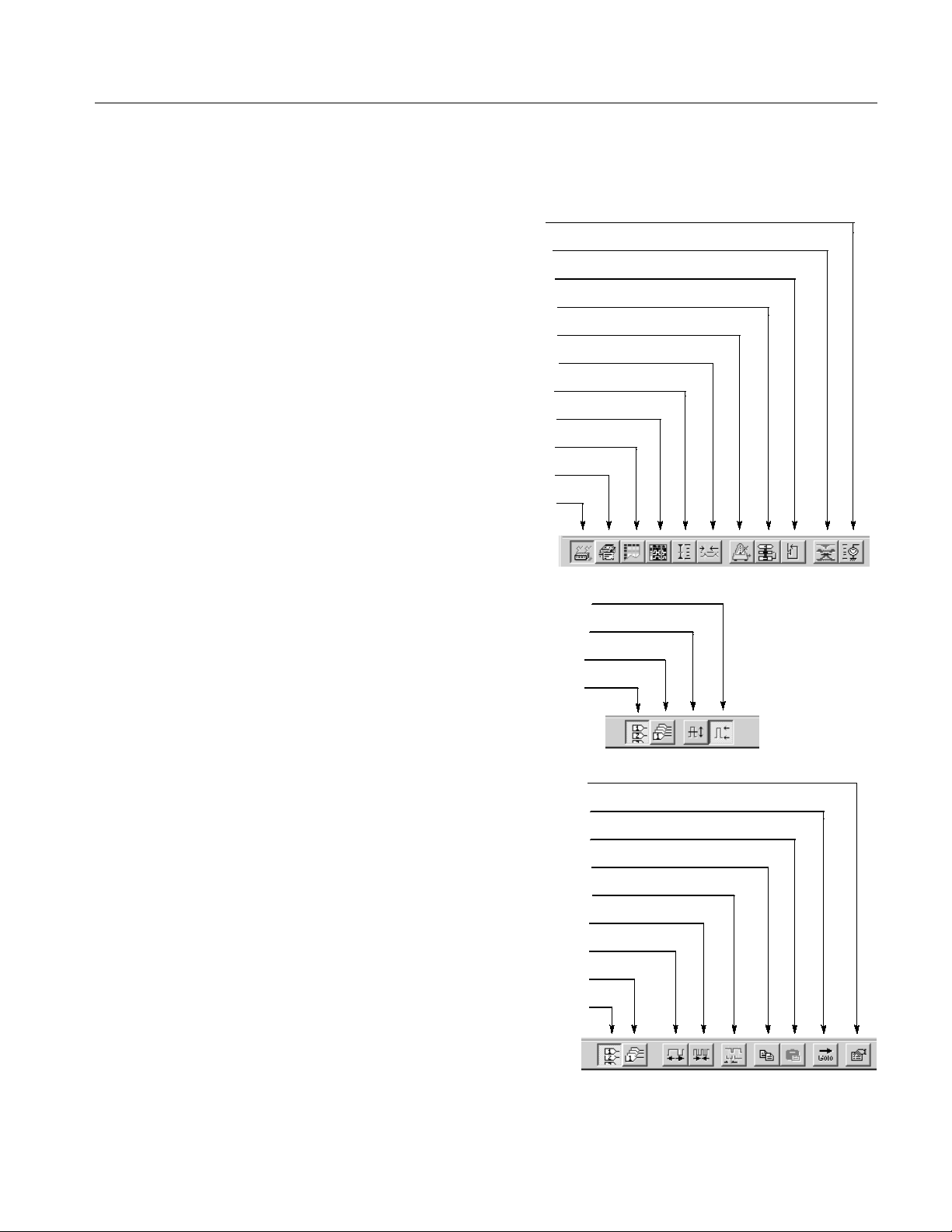
Toolbar. The toolbar contains the shortcut buttons for the data timing generator.
Accessing the toolbar requires a mouse. Two types of toolbars are provided; the
common toolbar to all windows and a specific toolbar for several windows. See
Figure 2--5.
DTG5078 & DTG5274 Data Timing Generator User Manual
Operating Basics
To hide or display the toolbar on the screen, select Toolbar from the View menu.
Click to open DC Output window
Click to open Jitter Generation window
Click to open Subsequence window
Click to open Sequence window
Click to open Time Base window
Click to open Timing window
Click to open Level window
Click to open Data-Waveform window
Click to open Data-Listing window
Click to open Blocks window
Click to open Channel Group window
Common toolbar
High/Low setting (Level window only)
Amplitude/Offset setting (Level window only)
Click to display pattern data by group
Click to display pattern data by channel
Level window or Timing window
Click to open Properties dialog
Click to open Move Cursor To dialog
Click to paste the copied item from the clipboard
Click to open Copy to Clipboard dialog
View with Timing (Data-Waveform window only)
Click to zoom out the display (Data-Waveform window only)
Click to zoom in the display (Data-Waveform window only)
Click to display pattern data by group
Click to display pattern data by channel
Data-Listing or Data-Waveform window
Figure 2--5: Toolbar
DTG5078 & DTG5274 Data Timing Generator User Manual
2--15
Operating Basics
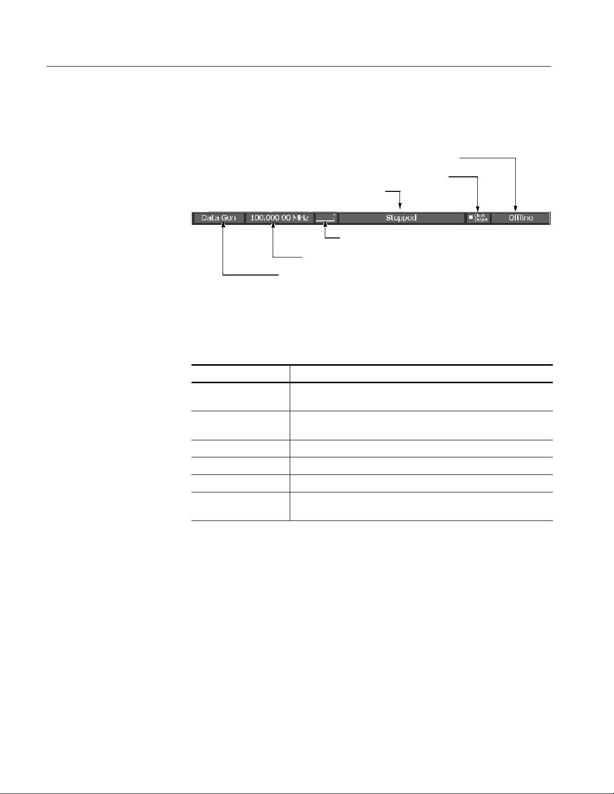
Status Bar. The stat us bar provides useful information about the state of the data
timing generator operation or setup.
Online/Offline
Clock output
Run status
Run status animation
User clock frequency
Operating mode button
Figure 2--6: Status bar
Table 2--8: Status Bar
Items Description
Operating mode button Displays the operating mode (Data Generator mode or Pulse
Generator mode). Click to toggle DG and PG modes.
User Clock frequency Displays the user clock frequency and period set by Timing window.
User clock frequency = H/W clock frequency / Vector rate
Run status animation Displays the sequencer status with animated screen.
Run status Displays the seqeuncer status.
Clock Output Displays the on/off of clock output.
Online/Offline Displays the DTG5000 software execution mode.
Appears only in the offline mode.
2--16
DTG5078 & DTG5274 Data Timing Generator User Manual

Operating Basics
Channel Group Window
The Channel Group window enables you to group the logical channels and
associate the logical channels with physical channels. The physical channels
represent the hardware channels which are actually installed in the data timing
generator. See Fi gure 2--7.
Figure 2--7: Channel Group window
H Group List. This list shows the logical channels comprising each of the
groups and the physical channels associated with the logical channels. By
default, the list shows the installed hardware channels (online mode) or
logical channels set by the DTG5000 Configuration Utility (offline mode).
The channels are grouped by eight channels.
H Channels. This list shows the actual installed channels (online mode) or
physical channels set by the DTG5000 Configuration Utility (offline mode).
Edit menu. This menu contains group editing and channel assignment commands.
Table 2--9: Edit menus for Channel Group window
Items Description
New Group... Creates a new group.
Delete Group Deletes the group you selected.
Delete All Group Deletes all the groups.
Rename/
Resize Group...
Renames the group you selected.
Changes the number of channels included in the group.
DTG5078 & DTG5274 Data Timing Generator User Manual
2--17

Operating Basics
Table 2--9: Edit menus for Channel Group window (cont.)
Items Description
Auto Assign Assigns physical channels installed in the data timing generator to
the logical channels in order.
De-assign All Clears all the logical and physical channels assignments.
De-assign Clears the physical channels assigned to the logical channels you
selected.
Preset
8 Channels per Group Defines the number of channels per group as 8.
1 Channel per Group Defines the number of channels per group as 1.
Blocks Window
All Channels in One
Group
Collects all the channels in a single group.
The basic data pattern is called “block” in the Data Generator mode. In the
Blocks window, you can create a new block, rename it, and resize or delete the
block.
2--18
Figure 2--8: Blocks window
DTG5078 & DTG5274 Data Timing Generator User Manual

Operating Basics
Table 2 --10 shows the setup items in the Blocks window.
Table 2--10: Setup items for Blocks window
Items Description
Block Name Specifies the block name.
Accepts up to 32 characters and 8,000 blocks.
Block Size Specifies the block size.
Up to 32,000,000 (DTG5274) or up to 8,000,000 (DTG5078).
Edit Menu. This menu contains commands that are used to delete blocks or move
them to the edit windows.
Table 2--11: Edit menus for Blocks window
Items Description
Edit Sets Block Name or Block Size.
View Listing Views the content of the selected block in the Data-Listing window,
where you can edit its content.
View Waveform Views the content of the selected block in the Data-Waveform
window, where you can edit its content.
Delete Deletes the block on the selected line.
DTG5078 & DTG5274 Data Timing Generator User Manual
2--19

Operating Basics
Data-Listing Window
In this window, a list of blocks is displayed in tabular form that can be edited.
The content edited in the Data-Listing window is the same as that of Data-Waveform window. The only difference is their display format. The Data-Listing
window displays the data as tabular form, while the Data-Waveform window
displays the data graphically. Because the data t o be edited is identical, the edited
data in either of the windows is automatically reflected in the other.
Figure 2--9: Data-Listing window
A table which indicates the blocks, a cursor, and a marker which specifies the
edit range are displayed in the window.
The table is displayed by channel or by group. In the group mode, you can select
one of various Radix display formats.
There are two methods to edit a pattern. Directly enter the numeric value to each
cell or use the Edit menu.
Sometimes the editing requires specifying t he edit range. You can specify all of
the current channels and groups, the channels and groups between markers, or
the area you specified with cursor.
2--20
DTG5078 & DTG5274 Data Timing Generator User Manual

Operating Basics
Edit Menu. This menu contains commands that create or edit various data
patterns, move the cursor or marker, switch between the channel and group
views, and sort the channels and groups listed.
Table 2--12: Edit menus for Data-Listing window
Items Description
Undo Reverses the previous change to the data.
Move Cursor To... Moves cursor.
Move Marker To... Moves Marker 1 or Marker 2.
Copy... Copies the data to the data timing generator clipboard.
Paste Pastes the data copied in the data timing generator clipboard on the
location starting from the active cursor cell.
Invert... Inverts the data between 0 and 1 in the specified range.
Mirror... Mirrors the data in the specified range in the vector or bitwise
direction.
Shift/Rotate... Moves the data in the specified range in the bitwise direction. Shift
fills the empty cells with 0s. Rotate fills them with the offscreen data.
Fill with One/Zero... Fills the specified range with 0s or 1s.
Clock Pattern... Fills the specified range with a clock pattern of 0s and 1s.
Predefined Pattern... Fills the specified range with a Binary Counter, Johnson Counter,
Graycode Counter, Walking Ones, Walking Zeros or Checker Board
pattern.
User Defined Pattern Fills the specified range with a pattern the user entered.
PRBS/PRWS... Fills the specified range with a pseudo random pattern.
Select Block... Select another block to be viewed or edited.
Copy to Clipboard... Copies the data in the specified range as characters to the Windows
clipboard.
Paste from Clipboard... Pastes the data copied in the Windows clipboard as characters to
the location starting from the active cursor cell. Also available for
importing data from other applications.
DTG5078 & DTG5274 Data Timing Generator User Manual
2--21
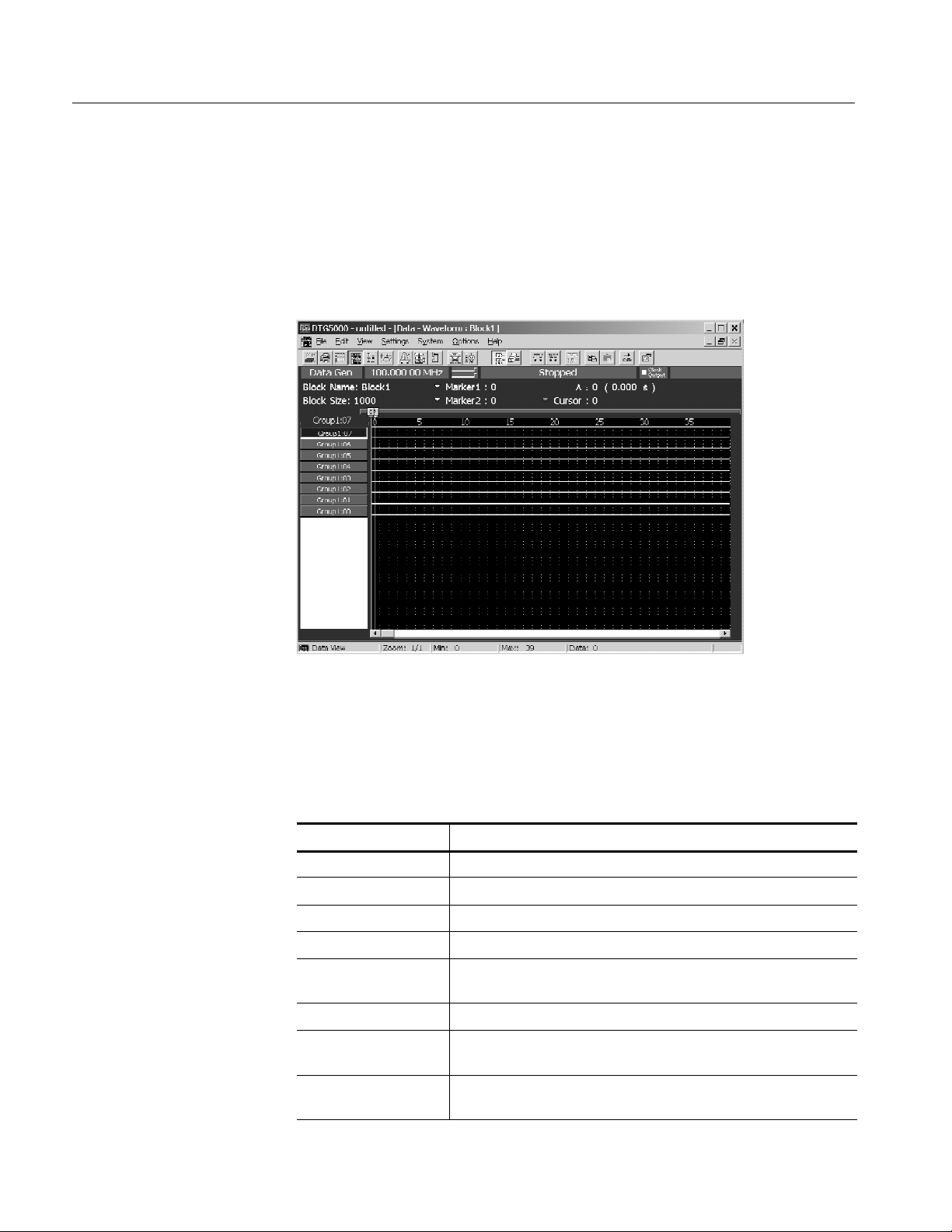
Operating Basics
Data-Waveform Window
In this window, the blocks are displayed graphically and they can be edited. The
content edited in the Data-Waveform window is the same as that of Data-Listing
window. The only difference is their display format. The Data-Listing window
displays the data as tabular form, while the Data-Waveform window displays the
data graphically. Because the data to be edited is identical, the edited data in
either of the windows is automatically reflected in the other.
Figure 2--10: Data-Waveform window
Edit Menu. This menu contains the same commands as the Data-Listing window.
Table 2--13: Edit menus for Data-Waveform window
Items Description
Undo Reverses the previous change to the data.
Move Cursor To... Moves cursor.
Move Marker To... Moves Marker 1 or Marker 2.
Copy... Copies the data to the data timing generator clipboard.
Paste Pastes the data copied in the data timing generator clipboard on the
location starting from the active cursor cell.
Invert... Inverts the data between 0 and 1 in the specified range.
Mirror... Mirrors the data in the specified range in the vector or bitwise
direction.
Shift/Rotate... Moves the data in the specified range in the bitwise direction. Shift
fills the empty cells with 0s. Rotate fills them with the offscreen data.
2--22
DTG5078 & DTG5274 Data Timing Generator User Manual

Operating Basics
Table 2--13: Edit menus for Data-Waveform window (cont.)
Items Description
Fill with One/Zero... Fills the specified range with 0s or 1s.
Clock Pattern... Fills the specified range with a clock pattern of 0s and 1s.
Predefined Pattern... Fills the specified range with a Binary Counter, Johnson Counter,
Graycode Counter, Walking Ones, Walking Zeros or Checker Board
pattern.
User Defined Pattern Fills the specified range with a pattern the user entered.
PRBS/PRWS... Fills the specified range with a pseudo random pattern.
Zoom In Doubles the size of the view horizontally, with the cursor position as
the base.
Zoom Out Halves the size of the view horizontally, with the cursor position as
the base.
Move Up Moves the current group position up one line. Available only when
the table is viewed by group.
Move Down Moves the current group position down one line. Available only when
the table is viewed by group.
Reset Order Arranges the channels within the current group according to their
numbers. Available only when the table is viewed by channel. Has
no influence on viewing in the Waveform window.
Properties... Specifies how data is listed when viewed by group (Magnitude).
Select Block... Select another block to be viewed or edited.
Copy to Clipboard... Copies the data in the specified range as text to the Windows
clipboard.
Paste from Clipboard... Pastes the data copied in the Windows clipboard as text to the
location starting from the active cursor cell. Also available for
importing data from another application.
DTG5078 & DTG5274 Data Timing Generator User Manual
2--23

Operating Basics
Level Window
In this window, you can set the High/Low levels and the termination voltage or
impedance for logic channel. It also allows you to turn the output to on or off.
The level of output signal can be specified by combining the High/Low levels or
Amplitude/Offset values.
Figure 2--11: Level window
The Level window allows you to setup the items for each channel. See Table
2--14.
Table 2--14: Setup items for Level window
Items Description
High Sets the High level value.
Low Sets the Low level value.
H Limit Sets the High level limit value.
L Limit Sets the Low level limit value.
Limit Turns on or off the High/Low limit feature.
Term R Sets the termination impedance of the destination of the output
signal.
Term V Sets the termination voltage of the destination of the output signal.
Output Turns the output to on or off.
2--24
DTG5078 & DTG5274 Data Timing Generator User Manual

Operating Basics
Edit Menu. The Edit menu of the Level window allows you to set the items
below. You can turn on or off Limit and Output, or you can specify Open to
Termination Impedance (Term.R), depending on the selection. The table 2--15
lists the common setting items regardless of the selection:
Table 2--15: Edit menus for Level window
Items Description
Predefined Level... Provides the following levels:
TTL (into open), TTL (into 50 Ω to GND),
CMOS 5 V (into open), CMOS 3.3 V (into open),
ECL (into 50 Ω to --2 V),
PECL (into 50 Ω to 3 V), PECL (into 50 Ω to 5 V),
LVPECL (into 50 Ω to 1.3 V), LVPECL (into 50 Ω to 3.3 V),
LVDS (into 100 Ω differential), TMDS (into 50 Ω to 3.3 V),
RSL (into 28 Ω to 1.8 V), CML (into 50 Ω to GND)
High/Low Specifies High and Low for the level setting.
Amplitude/Offset Specifies Amplitude and Offset for the level setting.
Apply to Channels in the
Same group
Apply to All Channels Applies the currently selected settings to all channels.
Applies the currently selected settings to all channels within the
group.
DTG5078 & DTG5274 Data Timing Generator User Manual
2--25
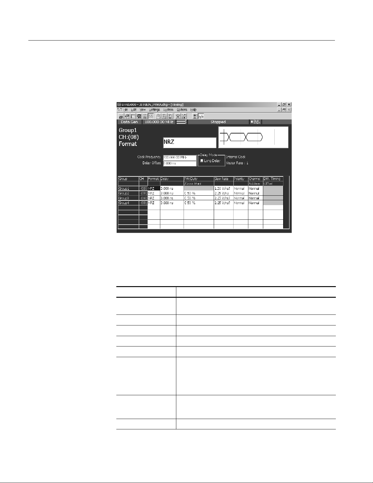
Operating Basics
Timing Window
In this window you can set the pattern format and time base parameters such as
the frequency, delay, pulse width and slew rate. Some of the settings parameters
are different in Data Generator mode and Pulse Generator mode.
Figure 2--12: Timing window (Data Generator mode)
Table 2--16: Setup items for Timing window
Items Description
Clock Frequency Sets the clock frequency of the data timing generator system. Either
Frequency or Period is available for this setting.
Delay Offset Sets the offset amount of the delay time.
Delay Mode Selects Long Delay on/off.
Clock Range Sets the clock range when Long Delay is on.
Vector Rate Vector rate (viewed only)
Internal Clock,
PLL Input,
External Reference
Input,
External Clock Input
Group Shows the group name when View by Group is selected.
CH Shows the physical channel assigned in the Channel Group window.
Shows current clock source or the frequency of the external clock
signal.
Alternatively shows both the group name and channel number when
View by Channel is selected.
2--26
DTG5078 & DTG5274 Data Timing Generator User Manual

Operating Basics
Table 2--16: Setup items for Timing window (cont.)
Items Description
Format Selects NRZ, RZ or R1 for the pattern format.
Delay Sets the lead delay (time or percentage).
PW/Duty/Cross Point Sets the pulse width or the duty when the format is set to RZ or R1.
Any of Duty(%), Pulse Width(s) or Trail Delay(s) is available for this
setting.
If the format is set to NRZ and the DTGM30 output module is
installed, you can change the cross point location by shifting the
rising or falling edge.
Slew Rate Sets the slew rate (V/ns). Unavailable for any channel to which a
DTGM30 channel has been assigned.
Polarity Selects Normal or Invert for the polarity of the pattern.
Channel Addition Sets the channel addition. Selects from Normal, XOR, or AND.
If the odd CH is assigned to physical channel, Normal and XOR can
be selected. If the even CH is assigned to physical channel, Normal
and AND can be selected.
Diff. Timing Offset Shifts timing for only inverted side of differential output.
Sets differential timing offset on/off and timing volume.
Edit Menu. The Edit menu of the Timing window contains the commands
common to the whole table and the commands available for the currently
selected item.
Table 2--17: Edit menus for Timing window
Items Description
Apply to Channels in the
Same Group
Apply to All Channels Sets the currently selected settings for all channels.
Differential Timing Offset
NRZ | RZ | R1 Selects the data format (when Format is selected).
Lead Delay | Phase(%) Specifies the rising position of a pulse (when Delay is selected).
Duty (%) | Pulse Width
(s) | Trail Delay (s)
Normal | Invert Sets the polarity (when Polarity is selected).
Sets the currently selected settings for all channels within the group.
Turns on or off the Differential Timing Offset of the currently selected
channels or group.
Specifies which is used to set the falling position of a pulse (when
PW/Duty is selected).
Normal | AND | XOR Sets the channel addition mode (when Channel Addition is selected).
DTG5078 & DTG5274 Data Timing Generator User Manual
2--27

Operating Basics
Time Base Window
The Time Base window allows you to specify the clock source, trigger source, or
event signal.
Figure 2--13: Time Base window
Table 2--18 shows setup items in the Time Base window.
Table 2--18: Setup items for Time Base window
Items Description
Clock Source
Internal Use internal clock.
External 10MHz Reference
External PLL Input: Use external PLL signal connected to Phase Lock In.
External Clock Input: Use signal connected to External Clock In as an external clock.
Clock Output
Amplitude Sets clock output signal amplitude.
Offset Sets offset.
Term .R Sets termination impedance.
Term .V Sets termination voltage.
Output On Specifies on/off of clock output.
Selects clock source.
Use 10 MHz reference clock connected to 10 MHz Reference In.
Sets the clock output parameters.
2--28
DTG5078 & DTG5274 Data Timing Generator User Manual

Operating Basics
Table 2--18: Setup items for Time Base window (cont.)
Items Description
Trigger
Source Selects trigger source from internal/external.
Slope Specifies the trigger point (rising edge or falling edge of external
Impedance Specifies external trigger impedance. (50 Ω or 1 kΩ)
Interval Specifies internal trigger interval.
Level Specifies external trigger level.
Sets the trigger parameters.
Specifying Internal allows to set the Interval.
Specifying External allows to set the Level, Slope and Impedance.
trigger signal). Selects either Positive or Negative.
Event Input
Polarity Specifies rising or falling edge. (Normal or Invert)
Impedance Specifies event signal input impedance. (50 Ω or 1 kΩ)
Threshold Specifies event signal input threshold level.
Sets the event input signal parameters.
There is no Edit menu on this window.
DTG5078 & DTG5274 Data Timing Generator User Manual
2--29

Operating Basics
Sequence Window
A sequence is a data structure of one or more combined blocks, where the data
timing generator can output more complex pattern. The Sequence window allows
you to define the blocks, the output sequence, the jumping method, and other
sequence conditions.
Figure 2--14: Sequence window
Table 2--19 shows setup items in the Sequence window.
Table 2--19: Setup items for Sequence window
Items Description
Label Sets the line name. Accepts up to 16 characters for each label name
and defines up to 8,000 lines. Labels defined may be used as
destinations of Event Jump To and/or Go To.
Wait. Trig. Specifies whether the system waits for triggering before outputting
the line. Selects On or Off (blank).
Block/Subsequence Specifies the name of the block or subsequence to be output on the
line. Accepts up to 32 characters for each name.
Repeat Specifies the number of repetitions of the block or subsequence.
Accepts an integer from 1 to 65,536 or Infinite.
Event Jump To Specifies the label of the line to which control jumps when an event
occurs while the contents of the current line are being output. If the
cell is left blank, control will not jump.
2--30
DTG5078 & DTG5274 Data Timing Generator User Manual

Operating Basics
Table 2--19: Setup items for Sequence window (cont.)
Items Description
Go To Specifies the label of the line to which control jumps unconditionally
after the contents of the current line are output. If the cell is left
blank, control goes to the next line.
Sequencer Mode Selects hardware sequence or software sequence.
Jump Mode Selects event jump (external event signal, front panel button, remote
commands) or command jump which is controlled by remote
commands.
Jump Timing Selects ASync which jumps immediately or Sync which does not
jump (waits for the completion of current blocks outputs).
Edit Menu. The Edit menu of the Sequence window contains commands not only
for the line operations, but also for the currently selected item.
Table 2--20: Edit menus for Sequence window
Items Description
Edit Edits Label, block name, subsequence name, or jump destination.
Wait Trigger Selects On or Off of Wait Trigger (when Wait Trig. is selected).
Infinite Selects Infinite for Repeat count (when Repeat is selected).
Delete Line Deletes the line that active cursor is placed.
Insert Line Before Inserts a blank line immediately above the line that active cursor is
placed.
Insert Line After Inserts a blank line immediately under the line that active cursor is
placed.
View Listing Changes the current window display to Data-Listing window, where
shows selected blocks. This menu selection is available when the
block name is selected.
View Waveform Changes the current window display to Data-Waveform window,
where shows selected blocks. This menu selection is available when
the block name is selected.
View Subsequence
Definition
Changes the current window display to Subsequence window, where
shows selected subsequences. This menu selection is available
when the subsequence is selected.
DTG5078 & DTG5274 Data Timing Generator User Manual
2--31

Operating Basics
Subsequence Window
A subsequence is a suite of the blocks used in the main sequence. In this window
you can define the subsequences that are used in the sequence.
Figure 2--15: Subsequence window
Subsequence List (left) contains the names of the currently defined subsequences. You can define up to 50 subsequences.
The right table lists the contents of the subsequence selected. For each subsequence, you can define up to 256 lines.
Table 2--21: Setup items for Subsequence window
Items Description
Block Specifies the name of the block to be output on the line. Accepts up
to 32 characters for each block name.
Repeat Specifies the number of repetitions of the block. Accepts an integer
from 1 to 65,536, but does not accept Infinite.
2--32
DTG5078 & DTG5274 Data Timing Generator User Manual

Operating Basics
Edit Menu. The Edit menu of the Subsequence window contains commands not
only for the line operations, but also for the currently selected item.
Table 2--22: Edit menus for Subsequence window
Items Description
Delete Line Deletes the line that active cursor is placed.
Insert Line Before Inserts a blank line immediately above the line that active cursor is
placed.
Insert Line After Inserts a blank line immediately under the line that active cursor is
placed.
View Listing Switches the window display to the Data-Listing window, where
shows selected blocks. This menu selection is available when the
block name is selected.
View Waveform Switches the window display to the Data-Waveform window, where
shows selected blocks. This menu selection is available when the
block name is selected.
DTG5078 & DTG5274 Data Timing Generator User Manual
2--33

Operating Basics
Jitter Generation Window
In this window you can set the parameters required for jitter generation. The
jitter generation is available only for Slot A, CH1.
Figure 2--16: Jitter Generation window
Table 2--23: Setup items for Jitter Generation window
Items Description
Jitter Generation on Slot
A CH1
Profile Selects jitter profile.
Edge Specifies the edge to apply a jitter.
Frequency Sets the repetitive frequency of the profile.
Amplitude Set the profile amplitude and jitter width. For the unit, you may select
Off: Turns off jitter generation.
All: Applies a jitter to the whole pattern of Slot A Ch1.
Partial: Partially applies a jitter to the pattern of Slot A Ch1.
The partial jitter is generated at the point logical channel set to 1.
You can select the logical channel using Partial By field.
either s (seconds) or UI (Unit Interval, 1 clock period of data timing
generator). Specifies peak-to-peak or RMS values.
There is no Edit menu on this window.
2--34
DTG5078 & DTG5274 Data Timing Generator User Manual

Operating Basics
DC Output Window
In this window you can set the parameters of the DC output located at the front
right of the data timing generator. Eight channel DC outputs are equipped with a
mainframe. While the system configuration is in Master-Slave mode, the master
machine can control the DC Outputs of all the slave machines.
Figure 2--17: DC Output window
The DC Output window allows you to set the following for each channel. See
Table 2--24.
Table 2--24: Setup items for DC Output window
Items Description
Level Sets the DC level value.
H Limit Sets the maximum value o f DC level setting range.
L Limit Sets the minimum value of DC level setting range.
Limit Turns on or off the High/Low limit function.
Output On Powers the output on or off.
DTG5078 & DTG5274 Data Timing Generator User Manual
2--35

Operating Basics
Edit Menu. Provides the predefined levels.
Table 2--25: Edit menus for DC output window
Items Description
TTL. High Sets 2.50 V.
Low Sets 0.00 V.
CMOS 5 V High Sets 5.00 V.
Low Sets 0.00 V.
CMOS 3.3 V High Sets 3.30 V.
Low Sets 0.00 V.
ECL High Sets --0.90 V.
Low Sets -- 1.70 V.
PECL High Sets 4.10 V.
Low Sets 3.30 V.
LVPECL High Sets 4.10 V.
Low Sets 1.60 V.
LVD S High Sets 1.40 V.
Low Sets 1.00 V.
TMDS High Sets 3.30 V.
Low Sets 2.80 V.
RSL High Sets 1.80 V.
Low Sets 1.00 V.
CML High Sets 0.00 V.
Low Sets -- 0.41 V.
2--36
DTG5078 & DTG5274 Data Timing Generator User Manual

Using the Menu System
Operating Basics
This section describes the basic operation of the data timing generator using the
front panel keys, buttons and knob.
Menu System
Pushing the front panel MENU button displays the last menu you selected on the
menu bar.
Figure 2--18: Menu selection
H To navigate through a pull-down menu list, use the Up or Down arrow key.
To show a submenu ("), use the Right arrow key. You can also use the knob
instead of the arrow keys to navigate through a menu list.
H If you press the Left or Right arrow key on a menu item not having any
submenu, you can navigate through the menu bar.
H Once you push the SELECT button, the menu is determined.
H To cancel the menu display, push the MENU button.
H To use the ESC key to cancel the menu display, press the ESC key twice.
When you press it only once, the menu bar is still active although the display
disappears. In this state, you can navigate through the menu bar by pressing
the Up, Down, Left, or Right arrow key.
Hint: Pressing the ALT key activates the menu bar. Then, you can make a menu
selection using the Up, Down, Left and/or Right arrow keys.
Pop-up Menu Items. In the individual data timing generator windows, selecting
the setup item and pushing the front panel SELECT button displays the pop-up
menu item(s) corresponding to the selected item. Refer to Figure 2--20 on page
2--39 for a pop-up menu example.
DTG5078 & DTG5274 Data Timing Generator User Manual
2--37
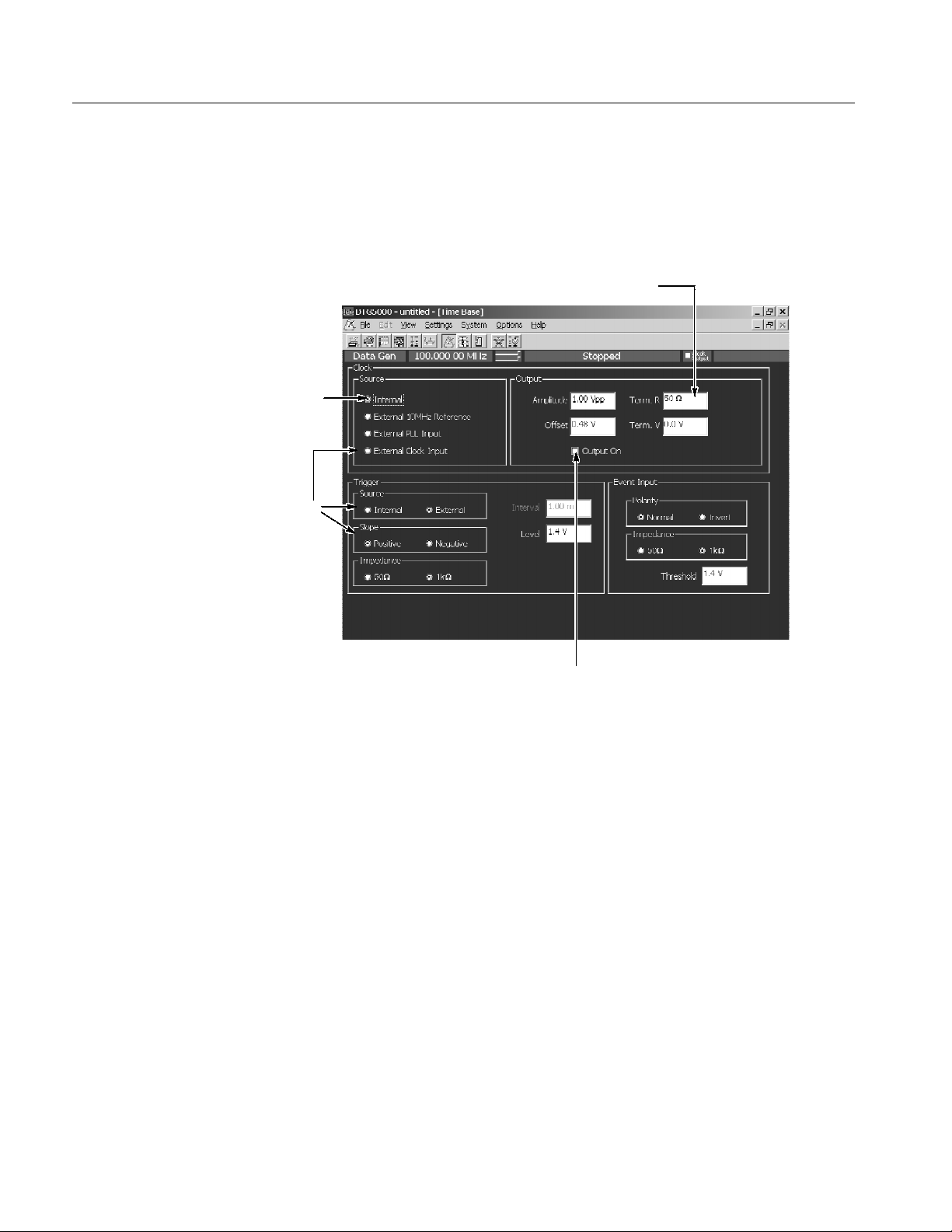
Operating Basics
Using a Window
The data timing generator windows contain various items of information. Input
of numeric values such as the output level and clock rate, selection of the trigger
source and other settings, creation of the pattern data, and other operations can
be performed.
4
1
2
3
Figure 2--19: Window operation 1: Time Base window
1. To select the parameter with radio buttons such as Clock Source or Trigger
Source, use the Up, Down, Left and/or Right arrow key.
2. To navigate through the Clock Source, Output Amplitude, and other similar
items, use the TAB key. You can navigate through these in the reverse
direction by pressing the SHIFT and TAB keys simultaneously.
3. To place the check sign into a check box such as Output On,usethe
SPACE key.
4. Any numeric input box has a unit attribute according to the setting. The unit
attribute s is for the time, V for the voltage, Ω for the resistance, or nothing
for the count or size. To enter a numeric value, use either numeric keys or the
knob. For details, see Numeric Input on page 2--44.
2--38
DTG5078 & DTG5274 Data Timing Generator User Manual
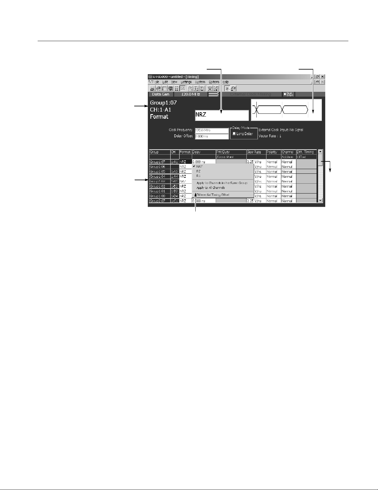
Operating Basics
2
1
4
5. Pop-up menu items
Figure 2--20: Window operation 2: Timing window
3
6
A table appears in the Timing, Level and Data-Listing windows. Figure 2--20
shows Timing window.
1. The information area shows the selected parameter information.
2. In the parameter box you can enter numeric values or characters.
3. A Pattern Display Box that contains a pattern corresponding to the Format or
Delay appears.
4. The parameter area at the lower part of the window lists the setting parameters such as Frequency or Delay. The parameters that can be set for each of
the channels are listed in tabular form.
5. A pop-up menu appears when an item is selected in the table, pushing the
SELECT button or right-clicking the mouse on the selected item displays
the menu items corresponding to the item.
For Format, Polarity, or Mode selections, first display the pop-up menu, then
select the parameter.
6. The scroll bar is activated when the mouse is attached. Scroll the cursor to
display the hidden tables outside the display area.
H To navigate through items in the parameter area, use the TAB key.
DTG5078 & DTG5274 Data Timing Generator User Manual
2--39
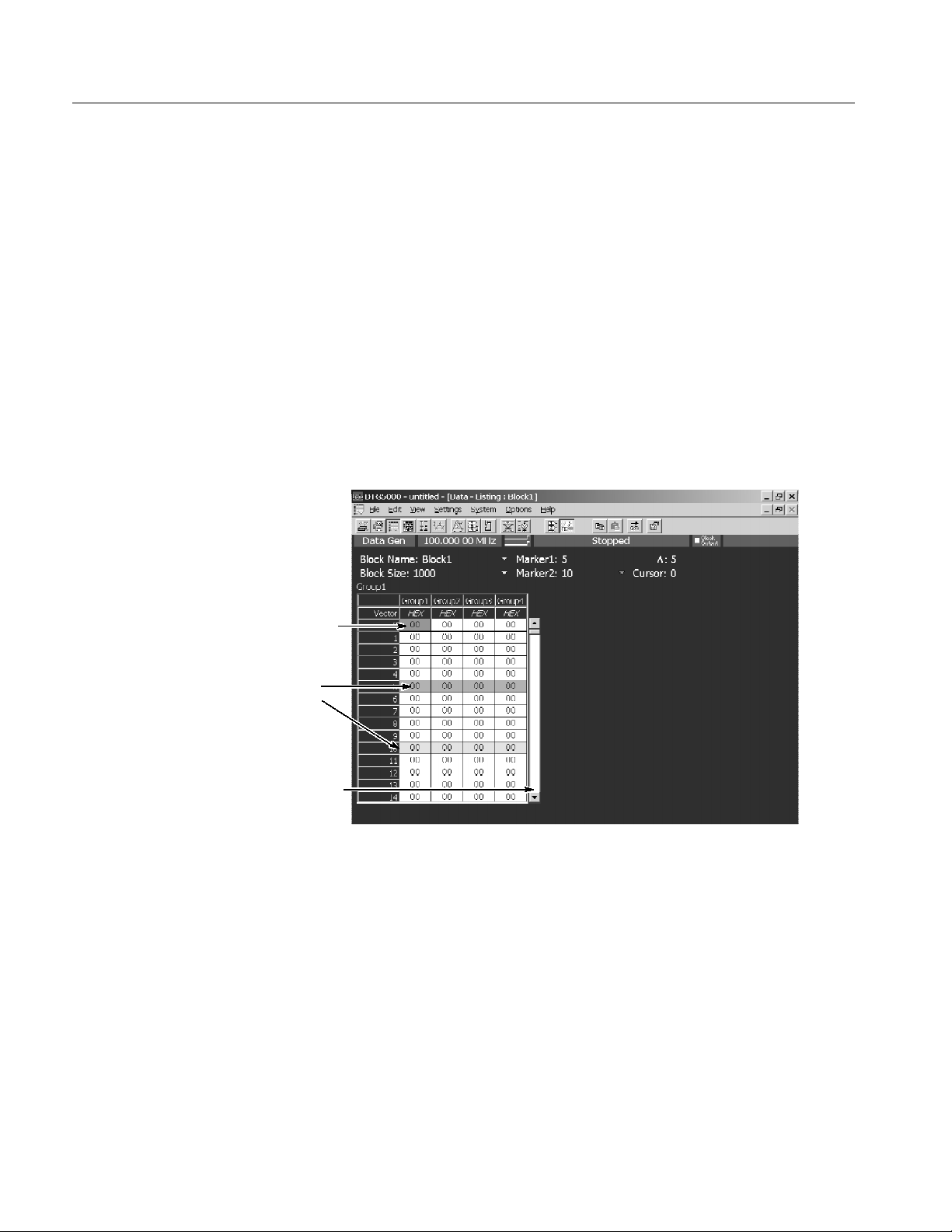
Operating Basics
H To move the cursor through items within the table, use the Up, Down, Left
or Right arrow key.
H In Polarity, you can toggle between its two options by pressing the SPACE
or ENTER key.
H For numeric parameters such as Delay or PW/Duty, enter numeric values
using numeric keys or the knob. See Numeric Input on page 2--44.
H You can select either View By Channel or View By Group window display.
You can toggle between the two by using View menu.
H You can select On or Off of Limit or Output parameter by pressing the
SPACE or ENTER key in the Level window.
1
3
2
Figure 2--21: Window operation 3: Data-Listing window
In the Data-Listing and Data-Waveform windows you can create or edit data. The
edit window allows you to use the cursor and markers to define the edit range.
1. You can move the cursor in the vector or bitwise direction by using the Up,
Down, Left, or Right arrow key.
To specify the region, use the Up, Down, Left, and/or Right arrow keys
while pressing the SHIFT key. Specifying the region is available within the
same group. It is not allowed to define the region beyond the group.
2--40
DTG5078 & DTG5274 Data Timing Generator User Manual
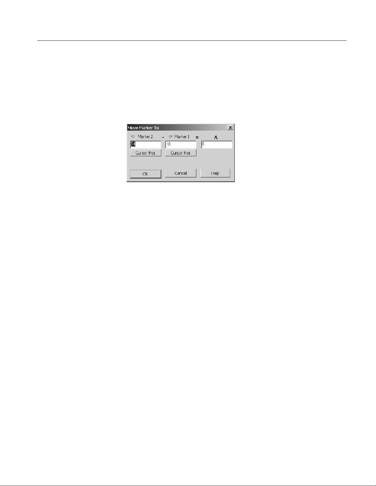
Operating Basics
2. The scroll bar is activated when the mouse is attached. Scroll the cursor to
display the hidden tables outside the display area.
3. The two markers are used to specify the range. To move the markers, select
Move Marker To... from the Edit menu to display the Move Marker To
dialog. Then, enter the value to each field.
H You cannot move the markers with front panel keys or knob.
H You can move the markers by dragging a mouse in the Data-Waveform
window.
H You can select either View By Channel or View By Group . You can toggle
the two displays by using the View menu.
DTG5078 & DTG5274 Data Timing Generator User Manual
2--41

Operating Basics
1
2
3
Figure 2--22: Window operation 4: Channel Group window
In the Channel Group window you can assign the logical channels and physical
channels. The Group List on the left window pane lists the logical channels in
the Group column. The Channels on the right side list the physical channels.
1. You can toggle between Group List and Channels using the TAB key.
2. To select a logical or physical channel, use the Up, Down, Left, and/or Right
arrow keys.
3. After selecting the physical channel in the Channels, pressing the ENTER
key makes the physical channel assign to the logical channel preselected in
the Group List. When you are using the mouse, you can make the assignment by clicking the mouse in the physical channel box.
H With the physical channels listed in the Group List (CH column), bullets are
added to the boxes associated with the assigned physical channels in the
Channels.
H After you have selected one of already assigned physical channels (indicated
by bullets) in the Channels, pressing the ENTER key resets (deassigns) the
assignment with the logical channel. If you are using the mouse, you can
reset the assignment by clicking the mouse in the assigned physical channel.
2--42
H To create, resize or deassign a group, or create a predefined group, use the
Edit menu or the pop-up menu displayed by pushing the SELECT button.
DTG5078 & DTG5274 Data Timing Generator User Manual

Operating Basics
3
2
1
4
Figure 2--23: Window operation 5: Sequence window
In the Sequence window you can create a sequence by combining blocks and
subsequences. This window is also in tabular form like other windows. This
window allows you to input the characters.
1. To move the active cell through the table, use the Up, Down, Left, and/or
Right arrow keys.
2. Any cell in this window accepts characters and digits you entered. To enter
characters to Label or Event Jump To column, press the front panel ALPHA
key to activate the text input mode and then use numeric keys. See Text Input
on page 2--45.
3. To specify On for Wait Trig. or Inf. for the Repeat, use the Edit menu. You
can also use the SELECT button to display the pop-up menu. See page 2--37
for information on how to use the data timing generator menu system.
4. The blocks and subsequences already defined in the Blocks or Subsequence
window are listed in the Edi t menu, which allows you to specify the block
or subsequence in the Block/Subsequence column. You can also specify the
the block or subsequence by using the SELECT button and pop-up menu.
DTG5078 & DTG5274 Data Timing Generator User Manual
2--43

Operating Basics
Numeric Input
Any numeric input box has a unit attribute according to the setting. The unit
attribute s is for the time, V for the voltage, Ω for the resistance, or nothing for
the count or size. The data timing generator recognizes the range of the
acceptable parameter values. If you enter a value outside the valid range, the
maximum or minimum value will be set automatically. To enter a numeric value,
use either numeric keys or the knob.
Using the Numeric Keys. Auxiliary unit keys such as k/m and M/ are available.
For k (kilo-), m (milli-), M (mega-), and their related units, the one suitable for
the parameter is selected automatically.
Example 1: Amplitude
H If you press 0, ., 5,andENTER in this order, 0.5 V is entered.
H If you press 5, 0, 0 ,andk/m in this order, 0.5 V (500 mV) is entered.
Example 2: Term Z
H If you press 5, 0,andENTER in this order, 50 Ω is entered.
H If you press 1 and M/ in this order, 1 MΩ is entered.
Using the Knob. If a numeric value is accompanied with an underbar, you can use
the knob for editing it. The digit accompanied with an underbar can be edited.
To move the underbar to the target digit to be edited, use the Left and/or Right
arrow key under the knob. See Figure 2--1 for the location of the key.
A numeric value accompanied
with underbar
Using the External Keyboard. Numeric keys above the alphabetical letter keys, not
those on the numeric keypad, are available on the external keyboard. The k
(kilo-), M (mega-), G (giga-), m (milli-), (micro-), n (nano-) and p (pico-) keys
are available for auxiliary units.
2--44
DTG5078 & DTG5274 Data Timing Generator User Manual

Operating Basics
Text Input
File Operations
To enter text from the front panel, use the ALPHA key and numeric keys. Push
the ALPHA key to activate the text input mode. In this mode, you can enter
characters that are printed above each numeric key. The ALPHA key’s LED stays
lit if the text input mode is selected.
H Pressing the ALPHA key switches between the numeric and text input
modes.
H By pressing a numeric key repeatedly, the characters indicated above the key
are displayed in order.
Example: Pressing the 8 key displays a at the caret. If you press the 8 key
repeatedly, the character changes to b, c, A, B, C and 8 in order.
H When you press another numeric key or the Left or Right arrow key, the
character currently displayed is determined and the caret moves. By pressing
the ENTER key or another numeric key, the character is also determined.
H If you press a key unrelated to text input or the ESC key, or use the ENTER
key to determine the character, the mode automatically changes from text
input to numeric input.
To save or load the setup file or import data that has been created on another
device, use the Windows standard file I/O dialog box. The data timing generator
file operations are the same as the general PC file operations. If the mouse is not
used, several restrictions are applied to the file operations.
Selecting a file. Do the followings steps to select a file without using a mouse.
1. Press the TAB key repeatedly to activate the file view.
Activates
the file
view
DTG5078 & DTG5274 Data Timing Generator User Manual
2--45

Operating Basics
2. Do the following substeps to specify the file within the file view area.
H Use Up or Down arrow key to select the folder.
H Press the ENTER key to open the folder.
H Press the BKSP key to move the folder hierarchy up.
Selects folder
with up or down
arrow key
3. Use Up or Down key to specify the file.
Selects file with
up or down
arrow key
H Press the ENTER key to open the file.
H Press the BKSP key to return to the upper folder.
2--46
DTG5078 & DTG5274 Data Timing Generator User Manual

Operating Basics
Key Operations
Table 2--26 summarizes the data timing generator key operations.
Table 2--26: Key operations
Items Description
MENU button Displays the last menu you opened on the menu bar.
TAB key Moves the focus through items in the window. Pressing SHIFT and
TAB keys simultaneously reverses the moving direction.
Up/Down/Left/Right
arrow keys
SHIFT + Up/Down/Left/
Right arrow keys
Knob Changes a numeric value, moves the cursor through menu items,
Digit Select arrow keys Located just below the knob. Moves the cursor through digits while
SPACE key Turns on or off the check sign in a check box, or toggles between
Moves the cursor through items on the menu, moves the caret during
text input, or selects a radio button.
Selects multiple items (Data-Listing/Data-Waveform window), or
shifts the current line (SHIFT + Up/Down arrow key only; Timing/Level window).
moves the focus in a table or list, moves the cursor through the
Data-Listing or Data-Waveform window, toggles between multiple
items for a parameter in the Timing/Level window (NRZ/RZ/R1,
On/Off, Normal/Invert, Normal/AND/XOR, etc.), or selects an item
from a combo box.
using the knob to enter a numeric value. Refer to page 2--2.
two options for a parameter in the Timing or Level window (On/Off,
Normal/Invert, etc.).
ALT key Activates the menu bar.
ALT + ESC key Switches the active application.
ALT + T AB key Switches the application (selected with icon display).
ALT + SPACE key Displays window control menu. You can move/resize/close the
window.
ALT + F4 Exits the application. (Available only from the external key board)
ESC key Cancels text input or a dialog box. Cancels display of a menu
opened with the SELECT key. To cancel a menu opened with the
MENU key, press ESC key twice.
CTRL + TAB key Switches the active window in the application.
CTRL + Left/Right arrow
key
CTRL + Up/Down key Increments or decrements the value during numeric input.
CTRL + ESC key Displays the Windows Start menu.
CTRL + ALT + DEL key Forcibly exits the application. (Available only from the external key
Moves the cursor between digits during numeric input.
board)
DTG5078 & DTG5274 Data Timing Generator User Manual
2--47

Operating Basics
Keyboard and Mouse
As the standard accessories, a USB keyboard and USB mouse are shipped with
the data timing generator. Though it is possible to operate the instrument only
with front panel controls, attaching the mouse and external keyboard to the data
timing generator mainframe makes the operation more easily. Read the following
topics related to the mouse and external keyboard.
When you set up the Windows operating system or perform the system recovery,
the external keyboard and mouse are required.
You can connect or remove the USB devices while the data timing generator
powered on.
Mouse.
H Using a mouse allows you to access the toolbar icons, each window buttons
and scroll bar which cannot be accessed from the data timing generator front
panel controls.
H In the data editing windows such as Data-Listing or Data-Waveform, or in
the setup windows such as Timing or Level, you can access the area you
cannot access from the keyboard. By dragging, right clicking or left clicking
the mouse allows you to access those functions.
Keyboard.
H The Delete and Back space (BS) functions are assigned to a single key. To
use it as BS, press Fn+Delete. If you want to use a key as labeled on the key
front (such as BS, F1, F2...), press it while holding down the Fn key.
H The Z key operates as the Windows key.
H You can assign the Delete key to the BS key using a SW3 DIP switch
located on the back. In this case, you can input Delete by pressing Fn+’.For
details of the DIP switches, refer to the underside of the keyboard.
H After you power on the instrument for the first time, you have to set up
Windows. Connect the keyboard supplied with the instrument before turning
on the power.
NOTE. If you need to perform the system recovery, you must use a PS/2 keyboard
and PS/2 mouse.
2--48
DTG5078 & DTG5274 Data Timing Generator User Manual

Data Structure
Internal Pattern Data
This section contains the following two subsections, which provides background
information on the DTG5000 Series Data Timing Generator data structure.
H Internal Pattern Data section explains the data timing generator objects such
as channel, group, block and sequence.
H Grouping and Channel Assignment section explains the definition of groups
and provides basic information on how to use the Channel Group window.
This section explains the meanings of the data included in the windows. The data
in the DTG software consists of the channel, group, block, and sequence objects.
This section details them in order.
Block
Group 01 Group 02 Group 03
Logical channel
Logical channel
Logical channel
Logical channel
Logical channel
Logical channel
Logical channel
Logical channel
Logical channel
Logical channel
Logical channel
Logical channel
Logical channel
Logical channel
Logical channel
Logical channel
1234
AB CD
1234 12341234
Figure 3--1: Channels, groups, blocks and channel assignment
DTG5078 & DTG5274 Data Timing Generator User Manual
Channel Assignment
Physical Channels
3--1

Data Structure
Logical Channel
Physical Channel
The data timing generator has two types of channels: logical and physical.
Logical channels represent one-bit pattern data. The number of logical channels
is 32 (= 4 channels x 8 slots) for the DTG5078, or 8 (= 2 channels x 4 slots) for
the DTG5274.
Logical channels themselves do not have the concept of length. The length of the
pattern data on a logical channel is the block size defined in the Blocks window.
Each piece of the pattern data has a value of 0 or 1. To create the pattern data,
you can use the Data-Listing or Data-Waveform window.
One of the key features of the data timing generator is that each logical channel
has its attribute value of the output setting parameters such as the output level,
pulse width or delay time. You can set these parameters using the Level and/or
Timing windows.
Physical channels are defined as the hardware channels of an output module
installed in the data timing generator mainframe. Each of the DTGM10 or
DTGM20 output module installed in the DTG5078 mainframe has four physical
channels. Each of the DTGM10 or DTGM20 module installed in the DTG5274
mainframe or each of the DTGM30 module installed in the DTG5078 or
DTG5274 mainframe has two physical channels.
The number of physical channels available for the system is determined by the
mainframe type and the types and number of output modules installed.
The DTG5000 software has the output setup parameters, such as the output level
or clock frequency, in its logical channels. To perform the actual data pattern
outputs, do the following:
H First, specify the physical channels to output the data within the logical
channels.
H Next, send the output setup parameter to the physical channels to operate the
hardware properly.
To associate the logical channel with the physical channel (this is also called
channel assignment), use the Channel Group window. Refer to Window
Operation 4: Channel Group Window on page 2--42.
3--2
DTG5078 & DTG5274 Data Timing Generator User Manual

Data Structure
Groups
Blocks
A group is defined as a set of logical channels. Grouping function is especially
useful depending on the DUT. Several channels are sometimes used with the
same output level and data format. In such case, handling the multiple channels
as one group is a useful method.
The number of logical channels that the system can accept is determined by the
mainframe (32 for the DTG5078 or 8 for the DTG5274). In the Master-Slave
operation mode, the number increases with the number of mainframes. The
number of groups depends on how many groups the user divides the logical
channels. The total number of logical channels of each group cannot exceed the
number of logical channels that the system can accept. By default, every logical
channel is divided into an eight-channel group. To add a new group, you have to
delete some groups or decrease the number of logical channels in a group to
secure the logical channels required for the new group.
To create, delete, rename or resize a group, use t he Channel Group window.
A block is defined as a set of groups that consist of logical channels. The block
is an elementary data of signal output. To specify the block length, use the block
size located in the Blocks window. The block size represents the pattern data
length, or vector length. The block width is the sum of bit width in the group to
which it belongs, that is, the total number of logical channels.
Sequence
By default, one block whose size is 1000 named Block1 is created.
Creating multiple blocks enables you to perform the repetitive signal outputs by
the blocks or sequential outputs with jumps. Even if two or more blocks exist in
the system, only one method can be used for either grouping or channel
assignment.
To create, rename or resize a block, use the Blocks window.
Use the Data-Listing or Data-Waveform window to edit values (0 and 1) in the
individual pattern data. Editing is possible by the block unit. To specify the
block to be edited, you can use Select Block... from the Edit menu of the
Data-Listing or Data-Waveform window, or use View Data-Listing or View
Data-Waveform from the Edit menu of the Blocks window.
To set the voltage output setting parameter, use the Level window. To set the
timing output setting parameter, use the Timing window. Both parameters can be
set by the channel unit (except for clock frequency), not by the block unit.
A sequence consists of blocks and subsequences. As the subsequence elements,
one or more block names and the repetition of the blocks are defined. Using a
sequence, you can output the complex signals by defining blocks, number of
repetition of subsequence, and jump conditions.
DTG5078 & DTG5274 Data Timing Generator User Manual
3--3

Data Structure
By default, a sequence that infinitely repeats the Block1 is provided. To create a
sequence or subsequence, use the sequence table in the Sequence window or
Subsequence window.
Data--Waveform window
Sequence window
Block1 x 10
Block2 x 20
Block3 x 10
Pattern Memory
Group
Group
Group
Block1
Block2
Block3
Data--Listing window
Edit
0100101001110
0010001000100
110011001
Level window
Hi 1.5 V
Lo 0.0 V
Output
Setup
Timing window
Freq 375 MHz
Delay 1 ns
Duty 50 %
3--4
Channel Assignment
Hardware channels
AB
Figure 3--2: Concept of data and window
DTG5078 & DTG5274 Data Timing Generator User Manual
Channel Group window
Grouping
12341234
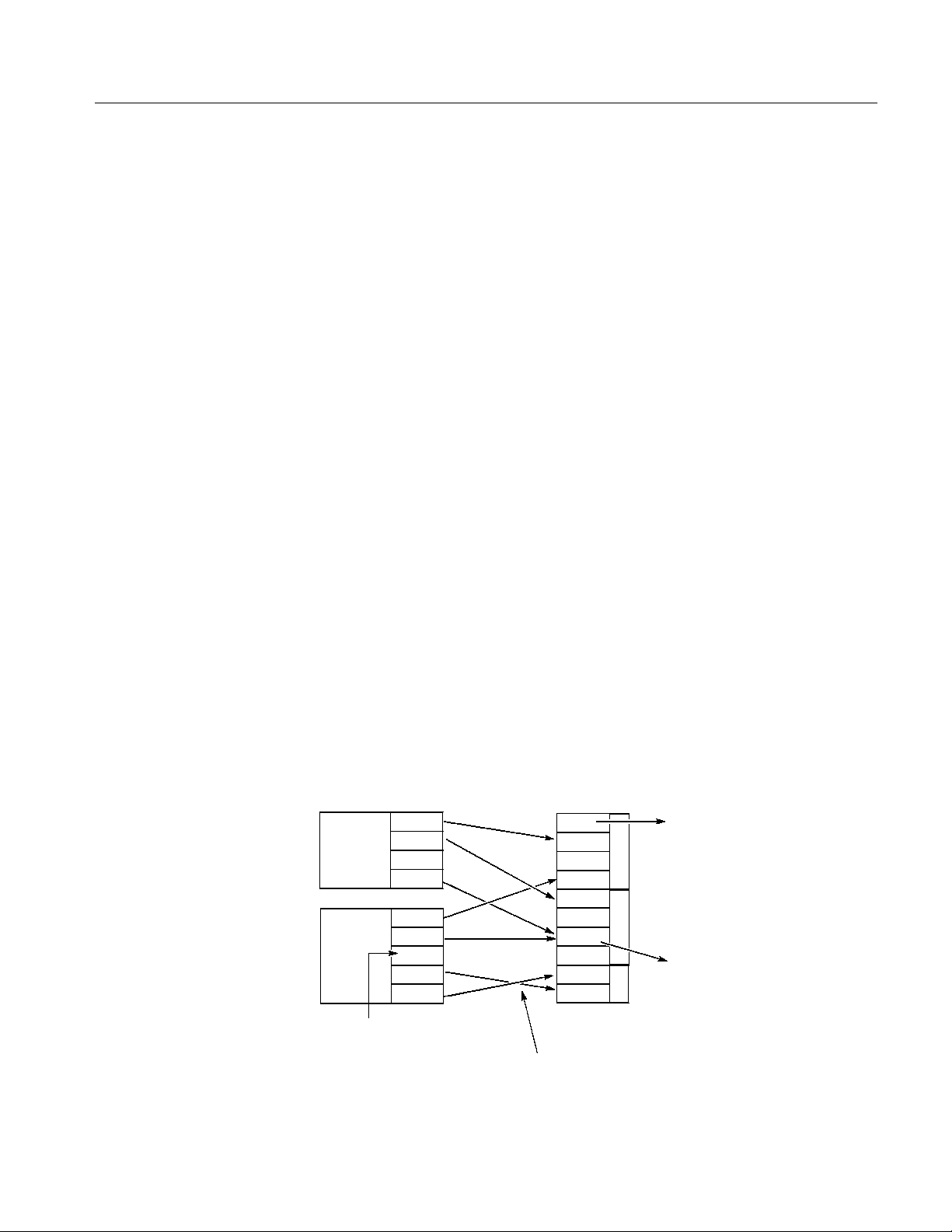
Grouping and Channel Assignment
Grouping is to collect channels in a single group to enable setup, edit or display
by group. To define a group or perform a channel assignment, use the Channel
Group window. You can use the grouping function only in the Data Generator
mode.
Data Structure
Defining a Group
Assigning a Channel
A group is defined by the name and the channels included in the group. The
defined group and channels are used for display by the channel or by the group
in the Data-Listing, Data-Waveform, Timing, or Level window.
The channels to be defined are logical channels but not physical channels, which
are actually installed to the hardware. The pattern data you created by pattern
edit and the setting parameters such as the voltage and/or delay are attributes
with logical channels.
To output a signal, you must assign the previously defined logical channels to
physical channels. See Figure 3--3.
H Assign only one physical channel to one logical channel.
H Channel assignment can be performed, regardless of the bit sequence in the
group; any physical channels can be assigned to logical channels as desired.
H You can define the logical channels without being assigned to physical
channels.
H The physical channels that are not assigned to the logical channels do not
output any signals.
Group
AAA
(4 bits)
BBB
(5 bits)
The logical channel which is not
assigned to any physical channel
can be used.
Logical
Channels
AAA:00
AAA:01
AAA:02
AAA:03
BBB:00
BBB:01
BBB:02
BBB:03
BBB:04
Figure 3--3: Channel assignment
DTG5078 & DTG5274 Data Timing Generator User Manual
Physical
Channels
CH1
CH2
CH3
CH4
CH1
CH2
X
CH3
CH4
CH1
CH2
Crossing is acceptable.
Slot A
Slot B
Slot C
Unable to use the CH1 which is
not assigned to logical channel.
You cannot assign two logical
channels to one physical channel.
3--5
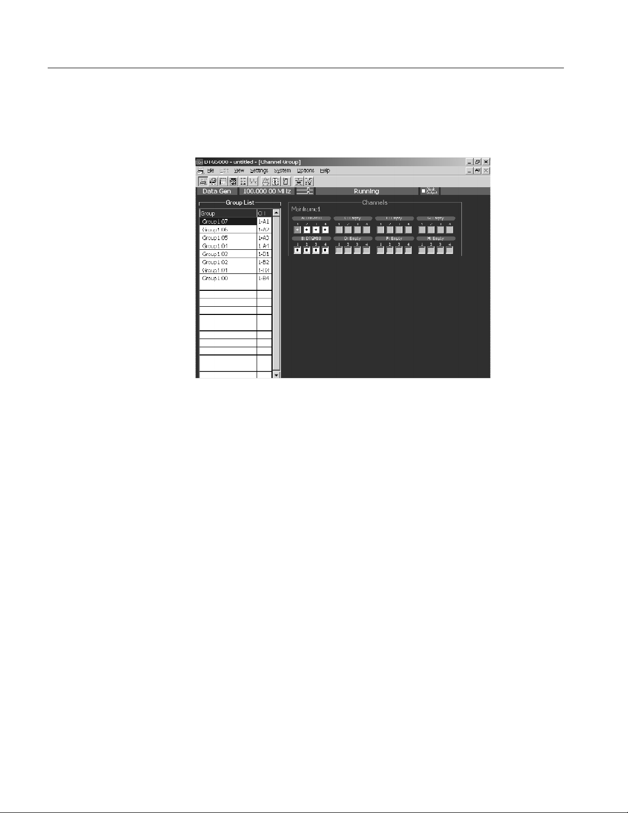
Data Structure
Channel Group Window
To define a group or perform channel assignment, use the Channel Group
window.
Figure 3--4: Channel Group window
Group List
The default group name(s) appear in the Group List represent the maximum
number of logical channels which can be used with mainframe, and they are
grouped by eight channel per one group. The groups are independent of the
installed output module(s).
Group Name. Assign a name to each group for identification. You can specify any
32-character or shorter string for a group. The name is case-sensitive, and the
default is GroupXX.
Definable Number. Equal to or less than the number of physical channels
supported by the mainframe. Up to 96.
Number of Channels. 1to96.
Predefined Grouping Options. The data timing generator provides three user-se-
lectable predefined options for grouping:
H 8 channels per group
H 1 channel per group
H All channels in one group
3--6
DTG5078 & DTG5274 Data Timing Generator User Manual

Data Structure
Creating a New Group
To create a new group, there must be a logical channel not assigned to a group.
By default, every logical channel has been assigned to groups in the data timing
generator mainframe. You must delete several groups to make the logical
channels availabl e before creating a new group.
1. Push the front panel MENU button.
2. Select the Edit menu, and then select New Group....
Alternatively, place the mouse pointer in the Group List table and right-click,
then select New Group....
3. The Grouping dialog box appears.
4. Enter a group name and the number of bits (number of logical channels) in
the dialog box.
Renaming and Resizing a
Group
5. Select OK to create a new group.
You can rename an existing group or change the number of its logical channels.
1. If the Group List is not activated on the screen, activate it by pressing the
TAB key.
2. Select the target group using the Up or Down arrow key.
3. Push the front panel MENU button.
4. Select the Edit menu, and then select Rename/Resize G roup....
Alternatively, place the mouse pointer in the Group List table and right-click,
andthenselecttheRename/Resize Group....
5. Edit the group name and the number of bits (the number of logical channels)
in the Grouping dialog box.
6. Select OK to complete the change.
DTG5078 & DTG5274 Data Timing Generator User Manual
3--7

Data Structure
Deleting a Group
Selecting a Preset
Grouping Option
You can delete the particular group(s) you selected or all the groups.
1. Activate the Group List in the Channel Group window.
2. To delete a group, select the group by using the Up or Down arrow key.
3. Push the front panel MENU button.
4. Select the Edit menu, and then select Delete Group or Delete All Groups.
Alternatively, place the mouse pointer in the Group List table and right-click,
andthenselecttheDelete Group or Delete All Groups.
5. Select the menu option (Delete Group or Delete All Groups) to display the
confirmation dialog box.
6. Select OK to delete the group(s).
The following three combinations of a group and its logical channel are provided
in the data timing generator.
H 8 channels per group
H 1 channel per group
H All channels per group
Channels
Physical Channel
To select one of these options, do the following.
1. Activate the Group List in the Channel Group window.
2. Push the front panel MENU button.
3. Select the Edit menu, and select Preset, and then select 8 Channels per
Group or 1 Channel per Group or All Channels in One Group.
Alternatively, place the mouse pointer in the Group List table and right-click,
then select the Preset, and then select 8 Channels per Group or 1 Channel
per Group or All Channels in O ne Group.
4. Select the menu item to display the confirmation dialog box.
5. Select OK to create the group.
The physical channel is identified by the mainframe number (1 to 3; for
Master-Slave configuration), slot location (A to H), and channel number (1 to 4).
The installed physical channels are displayed in the right window pane of display
area. Any channel indicated by a bullet in a white rectangle has already been
assigned to a logical channel.
3--8
DTG5078 & DTG5274 Data Timing Generator User Manual

Data Structure
Assigning a Channel
Using the Auto Assign
Function
Do the following steps to perform the channel assignment.
1. Activate the Group List in the Channel Group window.
2. Select the target logical channel with the Up or Down arrow key.
3. Activate the Channels with the TAB key.
4. Select a physical channel with the Up/Down/Left/Right arrow keys.
5. Push the SELECT button to complete the assignment. The physical channel
name is displayed in the CH column of the Group List, indicating that the
assignment is complete.
6. For the logical channel in the left of Group List, the next lower line is
selected automatically. The channel assignments can be performed in
sequence by repeating the selection of a physical channel in the right
Channels.
The Auto Assign function allows you to assign the physical channels (1-A1,
1-A2, 1-A3...) to the logical channels in the Group List sequentially.
1. Activate the Group List in the Channel Group window.
2. Push the front panel MENU button.
3. Select the Edit menu, and then select Auto Assign.
Alternatively, place the mouse pointer in the Group List table and right-click,
then select Auto Assign.
4. A confirmation dialog box appears.
5. Select OK to perform the Auto-Assign.
DTG5078 & DTG5274 Data Timing Generator User Manual
3--9

Data Structure
De-assigning a Channel
You can de-assign a physical channel you selected. You can also de-assign all the
physical channels currently assigned to logical channel(s).
1. Activate the Group List in the Channel Group window.
2. To de-assign a particular channel, select the channel with the Up or Down
arrow key.
3. Push the front panel MENU button.
4. Select the Edit menu, and then select De-assign or De-assign All.
Alternatively, place the mouse pointer in the Group List table and right-click,
then select the De-assign or De-assign All.
5. A dialog box appears to prompt you for confirmation. Select OK.
6. The channels you selected are de-assigned.
3--10
DTG5078 & DTG5274 Data Timing Generator User Manual

Tutorials
This section contains tutorials to help you learn how to operate the DTG5000
Series Data Timing Generator. These tutorials provide a good introduction to the
following basic features of the data timing generator.
The data timing generator has a high degree of flexibility in combination of the
mainframe and output modules. In this sect ion, you can perform the tutorials
under the assumption that the eight channel output modules (two DTGM10) are
installed in the data timing generator mainframe (DTG5078).
To familiarize the first-time user with the data timing generator, the following
tutorials focus on the front panel operations. In the actual signal output tasks,
you can perform the operations more easily by using a mouse and a keyboard.
Before Applying Power to
the Mainframe
Online Mode and
Offline Mode
Install two DTGM10 output modul es to slot A and slot B of the mainframe.
Refer to Output Module on page 1--7 for installation and removal of output
module. Then, power on the mainframe. Refer to Powering On the Data Timing
Generator on page 1--10.
The data timing generator starts in the mode in which it was powered off last
time. The offline mode enables you to set the whole process from creating
pattern data to setting up output parameter on the PC, except for the data timing
generator hardware control. To output a pattern, you must operate the data timing
generator in the online mode. If the data timing generator is running in the
offline mode, do the following steps to change the mode to online.
Indicates the
DTG is
operating in the
offline mode.
Figure 4--1: Confirming Offline mode
1. Exit the DTG5000 software.
a. Push the MENU button, and then select Exit from the File menu using
the Up, Down, Left, and/or Right arrow key.
DTG5078 & DTG5274 Data Timing Generator User Manual
4--1

Tutorials
b. Push the SELECT button to exit the DTG5000 software.
2. Start the DTG5000 Configuration Utility software.
a. Press the CTRL+ESC keys to open the Windows Start menu.
b. Using the Up, Down, Left, and/or Right arrow key, select Programs -- >
Tektronix -- > DTG5000 -- > DTG5000 Configuration Utility,andthen
press the ENTER key.
3. Use the DTG5000 Configuration Utility to set the mode to Online.
a. Press the TAB key repeatedly to activate the Mode selection.
b. Select Online using the Left or Right arrow key.
Select
Online
4--2
Figure 4--2: Select the online mode
c. The DTG5000 Configuration Utility window changes to online mode.
Press the ENTER key.
d. A dialog box appears to prompt you to restart the data timing generator.
Press the ENTER key.
4. Restart the DTG5000 software.
a. Press the CTRL+ESC keys to open the Start menu.
b. Using the arrow key, select Programs -- > Tektronix -- > DTG5000 -- >
DTG5000, and then press the ENTER key to restart the DTG5000
software.
DTG5078 & DTG5274 Data Timing Generator User Manual

Tutorials
Arrow Keys
There are two types of arrow keys on the data timing generator front panel.
Up, Down, Left, and Right arrow keys. These arrow keys are generally used to
move the cursor position or to navigate the menu items.
Digit Select arrow keys. These arrow keys are used to specify the digit to be
edited while using the knob to enter a numeric value.
Up, Down, Left, Right
arrow keys
Digit Select
arrow keys
In the following tutorials, the Up, Down, Left, and Right arrow keys are simply
called “arrow keys”.
DTG5078 & DTG5274 Data Timing Generator User Manual
4--3

Tutorials
Tutorial 1: Pulse Generator Mode
In this Tutorial 1, operate the data timing generator in the Pulse Generator mode,
and run the mainframe to output a pulse. Verify that the output signals vary by
changing several parameters.
Starting Pulse Generator
Mode
Starting the DTG5000 software causes the data timing generator to start in the
Data Generator mode.
1. Push the front panel MENU button, select Default Setup from the File
menu using the arrow keys, and then push the SELECT button.
2. Push the front panel PULSE GEN button to enter the Pulse Generator mode.
The Timebase window appears. In this window, you can set up parameters
related to the clock, run mode, and trigger. Use the default settings in this
tutorial. Confirm that Internal is selected in the Clock Source and Continu-
ous is selected in the Run Mode.
Confirm that
the Pulse Gen
is displayed
Confirm that
the Internal is
selected
Confirm that
the Continuous
is selected
4--4
Figure 4--3: Time Base window (Pulse Generator mode)
DTG5078 & DTG5274 Data Timing Generator User Manual

Tutorials
Browsing the Window
Output a Signal
1. Push the MENU button, select Level from the Settings menu using the
arrow keys, and then push the SELECT button. Alternatively, push the front
panel LEVEL button.
The Level window appears. In this window, you can set up parameters
related to the output level. By default, this window shows the High level
(1.000 V) and Low level (0.000 V) settings. You can use the default settings
in Tutorial 1. For the Level window screen sample, see Figure 4--4.
2. Push the MENU button, select Timing from the Settings menu using the
arrow keys, and then push the SELECT button. Alternatively, push the front
panel TIMING button.
The Timing window appears. In this window, you can set up parameters
related to the time base such as the output frequency, delay, and/or rise time.
For the Timing window screen sample, see Figure 4--5.
Output a signal with the default settings.
1. Push the front panel LEVEL button to open the Level window.
Figure 4--4: Level window (Pulse Generator mode)
2. Confirm that the View by Channel is selected in the View menu.
3. Do the following substeps to turn the Output on:
a. Move the cursor to Output 1-A1 usi ng the arrow keys.
DTG5078 & DTG5274 Data Timing Generator User Manual
4--5

Tutorials
b. Push the SELECT button to open the pop-up menu, select On using the
arrow keys, and then push the SELECT button. The Output for the
1-A1 channel is set to On.
Alternatively, you can press the SPACE or ENTER key to toggle
between On and Off.
Output is
set to On
NOTE. When the cursor is placed in a table in the Level, Timing or other
windows, you can push the SELECT button t o open the corresponding pop-up
menu that contains the commands for the current field. At the top, this menu
shows the setup parameter values specific to the item you selected. You can see
the same list in t he Edit menu which you can access by pushing the MENU
button.
Select from
Pop-up
menu
c. Press the Down arrow key to move the cursor to the 1-A2 channel. Press
the SPACE key to switch the channel status from Off to On.
d. Turn the outputs of 1-A3 and 1-A4 channels to On in the same way. The
LEDs stay lit up on the output connectors.
4--6
4. Push the front panel RUN button to output the pulse signal.
DTG5078 & DTG5274 Data Timing Generator User Manual
 Loading...