


Programmer Manual
DTG5000 Series
Data Timing Generators
071-1610-01
This document applies to program version 2.0.0 and above of
the DTG5000 Series.
www.tektronix.com

Copyright © Tektronix, Inc. All rights reserved. Licensed software products are owned by Tektronix or its subsidiaries
or suppliers, and are protected by national copyright laws and international treaty provisions.
Tektronix products are covered by U.S. and foreign patents, issued and pending. Information in this publication
supercedes that in all previously published material. Specifications and price change privileges reserved.
TEKTRONIX and TEK are registered trademarks of Tektronix, Inc.
Contacting Tektronix
Tektronix, Inc.
14200 SW Karl Braun Drive
P.O. Box 500
Beaverton, OR 97077
USA
For product information, sales, service, and technical support:
In North America, call 1-800-833-9200.
Worldwide, visit www.tektronix.com to find contacts in your area.

WARRANTY2
Tektronix warrants that this product will be free from defects in materials and workmanship for a period of one (1)
year from the date of shipment. If any such product proves defective during this warranty period, Tektronix, at its
option, either will repair the defective product without charge for parts and labor, or will provide a replacement in
exchange for the defective product. Parts, modules and replacement products used by Tektronix for warranty work may
be new or reconditioned to like new performance. All replaced parts, modules and products become the property of
Tektronix.
In order to obtain service under this warranty, Customer must notify Tektronix of the defect before the expiration of
the warranty period and make suitable arrangements for the performance of service. Customer shall be responsible for
packaging and shipping the defective product to the service center designated by Tektronix, with shipping charges
prepaid. Tektronix shall pay for the return of the product to Customer if the shipment is to a location within the country
in which the Tektronix service center is located. Customer shall be responsible for paying all shipping charges, duties,
taxes, and any other charges for products returned to any other locations.
This warranty shall not apply to any defect, failure or damage caused by improper use or improper or inadequate
maintenance and care. Tektronix shall not be obligated to furnish service under this warranty a) to repair damage
resulting from attempts by personnel other than Tektronix representatives to install, repair or service the product; b) to
repair damage resulting from improper use or connection to incompatible equipment; c) to repair any damage or
malfunction caused by the use of non-Tektronix supplies; or d) to service a product that has been modified or integrated
with other products when the effect of such modification or integration increases the time or difficulty of servicing the
product.
THIS WARRANTY IS GIVEN BY TEKTRONIX WITH RESPECT TO THE PRODUCT IN LIEU OF ANY
OTHER WARRANTIES, EXPRESS OR IMPLIED. TEKTRONIX AND ITS VENDORS DISCLAIM ANY
IMPLIED WARRANTIES OF MERCHANTABILITY OR FITNESS FOR A PARTICULAR PURPOSE.
TEKTRONIXÅf RESPONSIBILITY TO REPAIR OR REPLACE DEFECTIVE PRODUCTS IS THE SOLE
AND EXCLUSIVE REMEDY PROVIDED TO THE CUSTOMER FOR BREACH OF THIS WARRANTY.
TEKTRONIX AND ITS VENDORS WILL NOT BE LIABLE FOR ANY INDIRECT, SPECIAL,
INCIDENTAL, OR CONSEQUENTIAL DAMAGES IRRESPECTIVE OF WHETHER TEKTRONIX OR
THE VENDOR HAS ADVANCE NOTICE OF THE POSSIBILITY OF SUCH DAMAGES.


Table of Contents
Getting Started
Syntax and Commands
Preface . . . . . . . . . . . . . . . . . . . . . . . . . . . . . . . . . . . . . . . . . . . . . . . . . . . . . . . . . . . . . vii
Related Manuals. . . . . . . . . . . . . . . . . . . . . . . . . . . . . . . . . . . . . . . . . . . . . . . . . . . . . . . vii
Getting Started . . . . . . . . . . . . . . . . . . . . . . . . . . . . . . . . . . . . . . . . . . . . . . . . . . . . . 1-1
Manual Overview. . . . . . . . . . . . . . . . . . . . . . . . . . . . . . . . . . . . . . . . . . . . . . . . . . . . . 1-1
Setting Up Remote Communications Using GPIB . . . . . . . . . . . . . . . . . . . . . . . . . . . 1-3
Command Syntax . . . . . . . . . . . . . . . . . . . . . . . . . . . . . . . . . . . . . . . . . . . . . . . . . . . 2-1
SCPI Commands and Queries . . . . . . . . . . . . . . . . . . . . . . . . . . . . . . . . . . . . . . . . . . . 2-2
IEEE 488.2 Common Commands . . . . . . . . . . . . . . . . . . . . . . . . . . . . . . . . . . . . . . . 2-10
Specifying a Physical Channel. . . . . . . . . . . . . . . . . . . . . . . . . . . . . . . . . . . . . . . . . . 2-11
Syntax Diagrams . . . . . . . . . . . . . . . . . . . . . . . . . . . . . . . . . . . . . . . . . . . . . . . . . . . . 2-12
Command Groups . . . . . . . . . . . . . . . . . . . . . . . . . . . . . . . . . . . . . . . . . . . . . . . . . . 2-13
Functional Groups . . . . . . . . . . . . . . . . . . . . . . . . . . . . . . . . . . . . . . . . . . . . . . . . . . . 2-13
Command Quick Reference. . . . . . . . . . . . . . . . . . . . . . . . . . . . . . . . . . . . . . . . . . . . 2-14
Command Summaries . . . . . . . . . . . . . . . . . . . . . . . . . . . . . . . . . . . . . . . . . . . . . . . . 2-16
Command Descriptions . . . . . . . . . . . . . . . . . . . . . . . . . . . . . . . . . . . . . . . . . . . . . 2-21
BLOCk:DELete (No Query Form) . . . . . . . . . . . . . . . . . . . . . . . . . . . . . . . . . . . . . . 2-21
BLOCk:DELete:ALL (No Query Form) . . . . . . . . . . . . . . . . . . . . . . . . . . . . . . . . . . 2-21
BLOCk:LENGth (?). . . . . . . . . . . . . . . . . . . . . . . . . . . . . . . . . . . . . . . . . . . . . . . . . . 2-22
BLOCk:NEW (No Query Form) . . . . . . . . . . . . . . . . . . . . . . . . . . . . . . . . . . . . . . . . 2-22
BLOCk:SELect (?). . . . . . . . . . . . . . . . . . . . . . . . . . . . . . . . . . . . . . . . . . . . . . . . . . . 2-23
*CAL? (Query Only) . . . . . . . . . . . . . . . . . . . . . . . . . . . . . . . . . . . . . . . . . . . . . . . . . 2-23
CALibration[:ALL] (?) . . . . . . . . . . . . . . . . . . . . . . . . . . . . . . . . . . . . . . . . . . . . . . . 2-24
*CLS (No Query Form) . . . . . . . . . . . . . . . . . . . . . . . . . . . . . . . . . . . . . . . . . . . . . . . 2-25
DIAGnostic:DATA? (Query Only). . . . . . . . . . . . . . . . . . . . . . . . . . . . . . . . . . . . . . . 2-25
DIAGnostic:IMMediate (?) . . . . . . . . . . . . . . . . . . . . . . . . . . . . . . . . . . . . . . . . . . . . 2-26
DIAGnostic:SELect (?) . . . . . . . . . . . . . . . . . . . . . . . . . . . . . . . . . . . . . . . . . . . . . . . 2-27
*ESE (?) . . . . . . . . . . . . . . . . . . . . . . . . . . . . . . . . . . . . . . . . . . . . . . . . . . . . . . . . . . . 2-28
*ESR? (Query Only) . . . . . . . . . . . . . . . . . . . . . . . . . . . . . . . . . . . . . . . . . . . . . . . . . 2-28
GROup:DELete (No Query Form). . . . . . . . . . . . . . . . . . . . . . . . . . . . . . . . . . . . . . . 2-29
GROup:DELete:ALL (No Query Form) . . . . . . . . . . . . . . . . . . . . . . . . . . . . . . . . . . 2-29
GROup:NEW (No Query Form) . . . . . . . . . . . . . . . . . . . . . . . . . . . . . . . . . . . . . . . . 2-30
GROup:WIDTh (?) . . . . . . . . . . . . . . . . . . . . . . . . . . . . . . . . . . . . . . . . . . . . . . . . . . 2-30
*IDN? (Query Only) . . . . . . . . . . . . . . . . . . . . . . . . . . . . . . . . . . . . . . . . . . . . . . . . . 2-31
JGENeration:AMPLitude (?) . . . . . . . . . . . . . . . . . . . . . . . . . . . . . . . . . . . . . . . . . . . 2-31
JGENeration:AMPLitude:UNIT (?) . . . . . . . . . . . . . . . . . . . . . . . . . . . . . . . . . . . . . 2-32
JGENeration:EDGE (?) . . . . . . . . . . . . . . . . . . . . . . . . . . . . . . . . . . . . . . . . . . . . . . . 2-33
JGENeration:FREQuency (?). . . . . . . . . . . . . . . . . . . . . . . . . . . . . . . . . . . . . . . . . . . 2-34
JGENeration:GSOurce (?) . . . . . . . . . . . . . . . . . . . . . . . . . . . . . . . . . . . . . . . . . . . . . 2-34
JGENeration:MODE (?) . . . . . . . . . . . . . . . . . . . . . . . . . . . . . . . . . . . . . . . . . . . . . . 2-35
JGENeration:PROFile (?) . . . . . . . . . . . . . . . . . . . . . . . . . . . . . . . . . . . . . . . . . . . . . 2-36
DTG5000 Series Data Timing Generators Programmer Manual i

Table of Contents
JGENeration[:STATe] (?) . . . . . . . . . . . . . . . . . . . . . . . . . . . . . . . . . . . . . . . . . . . . . . 2-37
MMEMory:LOAD (No Query Form). . . . . . . . . . . . . . . . . . . . . . . . . . . . . . . . . . . . . 2-38
MMEMory:STORe (No Query Form) . . . . . . . . . . . . . . . . . . . . . . . . . . . . . . . . . . . . 2-38
*OPC (?) . . . . . . . . . . . . . . . . . . . . . . . . . . . . . . . . . . . . . . . . . . . . . . . . . . . . . . . . . . . 2-38
*OPT? (Query Only). . . . . . . . . . . . . . . . . . . . . . . . . . . . . . . . . . . . . . . . . . . . . . . . . . 2-39
OUTPut:CLOCk:AMPLitude (?) . . . . . . . . . . . . . . . . . . . . . . . . . . . . . . . . . . . . . . . . 2-40
OUTPut:CLOCk:OFFSet (?). . . . . . . . . . . . . . . . . . . . . . . . . . . . . . . . . . . . . . . . . . . . 2-40
OUTPut:CLOCk[:STATe] (?) . . . . . . . . . . . . . . . . . . . . . . . . . . . . . . . . . . . . . . . . . . . 2-41
OUTPut:CLOCk:TIMPedance(?) . . . . . . . . . . . . . . . . . . . . . . . . . . . . . . . . . . . . . . . . 2-41
OUTPut:CLOCk:TVOLtage(?). . . . . . . . . . . . . . . . . . . . . . . . . . . . . . . . . . . . . . . . . . 2-42
OUTPut:DC:HLIMit(?). . . . . . . . . . . . . . . . . . . . . . . . . . . . . . . . . . . . . . . . . . . . . . . . 2-42
OUTPut:DC:LEVel(?). . . . . . . . . . . . . . . . . . . . . . . . . . . . . . . . . . . . . . . . . . . . . . . . . 2-43
OUTPut:DC:LIMit(?) . . . . . . . . . . . . . . . . . . . . . . . . . . . . . . . . . . . . . . . . . . . . . . . . . 2-44
OUTPut:DC:LLIMit(?) . . . . . . . . . . . . . . . . . . . . . . . . . . . . . . . . . . . . . . . . . . . . . . . . 2-45
OUTPut:DC[:STATe] (?). . . . . . . . . . . . . . . . . . . . . . . . . . . . . . . . . . . . . . . . . . . . . . . 2-46
OUTPut:STATe:ALL (No Query Form) . . . . . . . . . . . . . . . . . . . . . . . . . . . . . . . . . . . 2-46
PGEN<x>[<m>]:CH<n>:AMODe (?) . . . . . . . . . . . . . . . . . . . . . . . . . . . . . . . . . . . . 2-47
PGEN<x>[<m>]:CH<n>:AMPLitude(?) . . . . . . . . . . . . . . . . . . . . . . . . . . . . . . . . . . 2-48
PGEN<x>[<m>]:CH<n>:BDATa(?). . . . . . . . . . . . . . . . . . . . . . . . . . . . . . . . . . . . . . 2-49
PGEN<x>[<m>]:CH<n>:CPOint(?). . . . . . . . . . . . . . . . . . . . . . . . . . . . . . . . . . . . . . 2-50
PGEN<x>[<m>]:CH<n>:DATA(?). . . . . . . . . . . . . . . . . . . . . . . . . . . . . . . . . . . . . . . 2-51
PGEN<x>[<m>]:CH<n>:DCYCle(?). . . . . . . . . . . . . . . . . . . . . . . . . . . . . . . . . . . . . 2-52
PGEN<x>[<m>]:CH<n>:DTOFfset(?). . . . . . . . . . . . . . . . . . . . . . . . . . . . . . . . . . . . 2-53
PGEN<x>[<m>]:CH<n>:DTOFfset:STATe(?) . . . . . . . . . . . . . . . . . . . . . . . . . . . . . . 2-54
PGEN<x>[<m>]:CH<n>:HIGH(?). . . . . . . . . . . . . . . . . . . . . . . . . . . . . . . . . . . . . . . 2-55
PGEN<x>[<m>]:CH<n>:HLIMit(?) . . . . . . . . . . . . . . . . . . . . . . . . . . . . . . . . . . . . . 2-56
PGEN<x>[<m>]:CH<n>:IMPedance? (Query Only). . . . . . . . . . . . . . . . . . . . . . . . . 2-57
PGEN<x>[<m>]:CH<n>:JRANge? . . . . . . . . . . . . . . . . . . . . . . . . . . . . . . . . . . . . . . 2-57
PGEN<x>[<m>]:CH<n>:LDELay(?). . . . . . . . . . . . . . . . . . . . . . . . . . . . . . . . . . . . . 2-58
PGEN<x>[<m>]:CH<n>:LHOLd(?) . . . . . . . . . . . . . . . . . . . . . . . . . . . . . . . . . . . . . 2-59
PGEN<x>[<m>]:CH<n>:LIMit(?) . . . . . . . . . . . . . . . . . . . . . . . . . . . . . . . . . . . . . . . 2-60
PGEN<x>[<m>]:CH<n>:LLIMit(?). . . . . . . . . . . . . . . . . . . . . . . . . . . . . . . . . . . . . . 2-61
PGEN<x>[<m>]:CH<n>:LOW(?) . . . . . . . . . . . . . . . . . . . . . . . . . . . . . . . . . . . . . . . 2-62
PGEN<x>[<m>]:CH<n>:OFFSet(?) . . . . . . . . . . . . . . . . . . . . . . . . . . . . . . . . . . . . . 2-63
PGEN<x>[<m>]:CH<n>:OUTPut(?) . . . . . . . . . . . . . . . . . . . . . . . . . . . . . . . . . . . . . 2-64
PGEN<x>[<m>]:CH<n>:PHASe(?). . . . . . . . . . . . . . . . . . . . . . . . . . . . . . . . . . . . . . 2-65
PGEN<x>[<m>]:CH<n>:POLarity(?) . . . . . . . . . . . . . . . . . . . . . . . . . . . . . . . . . . . . 2-66
PGEN<x>[<m>]:CH<n>:PRATe(?) . . . . . . . . . . . . . . . . . . . . . . . . . . . . . . . . . . . . . . 2-67
PGEN<x>[<m>]:CH<n>:SLEW(?) . . . . . . . . . . . . . . . . . . . . . . . . . . . . . . . . . . . . . . 2-68
PGEN<x>[<m>]:CH<n>:TDELay(?). . . . . . . . . . . . . . . . . . . . . . . . . . . . . . . . . . . . . 2-69
PGEN<x>[<m>]:CH<n>:THOLd(?) . . . . . . . . . . . . . . . . . . . . . . . . . . . . . . . . . . . . . 2-70
PGEN<x>[<m>]:CH<n>:TIMPedance(?) . . . . . . . . . . . . . . . . . . . . . . . . . . . . . . . . . 2-71
PGEN<x>[<m>]:CH<n>:TVOLtage(?) . . . . . . . . . . . . . . . . . . . . . . . . . . . . . . . . . . . 2-72
PGEN<x>[<m>]:CH<n>:TYPE(?). . . . . . . . . . . . . . . . . . . . . . . . . . . . . . . . . . . . . . . 2-73
PGEN<x>[<m>]:CH<n>:WIDTh(?) . . . . . . . . . . . . . . . . . . . . . . . . . . . . . . . . . . . . . 2-74
PGEN<x>[<m>]:ID? (Query Only) . . . . . . . . . . . . . . . . . . . . . . . . . . . . . . . . . . . . . . 2-75
*RST (No Query Form) . . . . . . . . . . . . . . . . . . . . . . . . . . . . . . . . . . . . . . . . . . . . . . . 2-75
SEQuence:DATA(?) . . . . . . . . . . . . . . . . . . . . . . . . . . . . . . . . . . . . . . . . . . . . . . . . . . 2-76
SEQuence:LENGth(?). . . . . . . . . . . . . . . . . . . . . . . . . . . . . . . . . . . . . . . . . . . . . . . . . 2-77
SIGNal:ASSign(?). . . . . . . . . . . . . . . . . . . . . . . . . . . . . . . . . . . . . . . . . . . . . . . . . . . . 2-78
SIGNal:<parameter>(?). . . . . . . . . . . . . . . . . . . . . . . . . . . . . . . . . . . . . . . . . . . . . . . . 2-79
ii DTG5000 Series Data Timing Generators Programmer Manual

Table of Contents
SIGNal:BDATa(?) . . . . . . . . . . . . . . . . . . . . . . . . . . . . . . . . . . . . . . . . . . . . . . . . . . . 2-80
SIGNal:DATA(?) . . . . . . . . . . . . . . . . . . . . . . . . . . . . . . . . . . . . . . . . . . . . . . . . . . . . 2-81
SIGNal:IMPedance? (Query Only) . . . . . . . . . . . . . . . . . . . . . . . . . . . . . . . . . . . . . . 2-82
SIGNal:JRANge(?) . . . . . . . . . . . . . . . . . . . . . . . . . . . . . . . . . . . . . . . . . . . . . . . . . . 2-82
*SRE (?). . . . . . . . . . . . . . . . . . . . . . . . . . . . . . . . . . . . . . . . . . . . . . . . . . . . . . . . . . . 2-83
*STB? (Query Only) . . . . . . . . . . . . . . . . . . . . . . . . . . . . . . . . . . . . . . . . . . . . . . . . . 2-84
SUBSequence:DATA(?). . . . . . . . . . . . . . . . . . . . . . . . . . . . . . . . . . . . . . . . . . . . . . . 2-84
SUBSequence:DELete (No Query Form) . . . . . . . . . . . . . . . . . . . . . . . . . . . . . . . . . 2-85
SUBSequence:DELete:ALL (No Query Form). . . . . . . . . . . . . . . . . . . . . . . . . . . . . 2-85
SUBSequence:LENGth(?) . . . . . . . . . . . . . . . . . . . . . . . . . . . . . . . . . . . . . . . . . . . . . 2-86
SUBSequence:NEW (No Query Form) . . . . . . . . . . . . . . . . . . . . . . . . . . . . . . . . . . . 2-86
SUBSequence:SELect(?) . . . . . . . . . . . . . . . . . . . . . . . . . . . . . . . . . . . . . . . . . . . . . . 2-87
SYSTem:ERRor[:NEXT]? (Query Only) . . . . . . . . . . . . . . . . . . . . . . . . . . . . . . . . . 2-87
SYSTem:KLOCk (?) . . . . . . . . . . . . . . . . . . . . . . . . . . . . . . . . . . . . . . . . . . . . . . . . . 2-88
SYSTem:VERSion? (Query Only) . . . . . . . . . . . . . . . . . . . . . . . . . . . . . . . . . . . . . . 2-89
TBAS:COUNt(?) . . . . . . . . . . . . . . . . . . . . . . . . . . . . . . . . . . . . . . . . . . . . . . . . . . . . 2-89
TBAS:CRANge(?). . . . . . . . . . . . . . . . . . . . . . . . . . . . . . . . . . . . . . . . . . . . . . . . . . . 2-90
TBAS:DOFFset(?) . . . . . . . . . . . . . . . . . . . . . . . . . . . . . . . . . . . . . . . . . . . . . . . . . . . 2-91
TBAS:EIN:IMMediate (No Query Form) . . . . . . . . . . . . . . . . . . . . . . . . . . . . . . . . . 2-91
TBAS:EIN:IMPedance(?) . . . . . . . . . . . . . . . . . . . . . . . . . . . . . . . . . . . . . . . . . . . . . 2-92
TBAS:EIN:LEVel(?) . . . . . . . . . . . . . . . . . . . . . . . . . . . . . . . . . . . . . . . . . . . . . . . . . 2-92
TBAS:EIN:POLarity(?) . . . . . . . . . . . . . . . . . . . . . . . . . . . . . . . . . . . . . . . . . . . . . . . 2-93
TBAS:FREQuency(?) . . . . . . . . . . . . . . . . . . . . . . . . . . . . . . . . . . . . . . . . . . . . . . . . 2-93
TBAS:JMODe(?) . . . . . . . . . . . . . . . . . . . . . . . . . . . . . . . . . . . . . . . . . . . . . . . . . . . . 2-94
TBAS:JTIMing(?) . . . . . . . . . . . . . . . . . . . . . . . . . . . . . . . . . . . . . . . . . . . . . . . . . . . 2-95
TBAS:JUMP (No Query Form). . . . . . . . . . . . . . . . . . . . . . . . . . . . . . . . . . . . . . . . . 2-95
TBAS:LDELay (?). . . . . . . . . . . . . . . . . . . . . . . . . . . . . . . . . . . . . . . . . . . . . . . . . . . 2-96
TBAS:MODE(?) . . . . . . . . . . . . . . . . . . . . . . . . . . . . . . . . . . . . . . . . . . . . . . . . . . . . 2-96
TBAS:OMODe(?) . . . . . . . . . . . . . . . . . . . . . . . . . . . . . . . . . . . . . . . . . . . . . . . . . . . 2-97
TBAS:PERiod(?) . . . . . . . . . . . . . . . . . . . . . . . . . . . . . . . . . . . . . . . . . . . . . . . . . . . . 2-98
TBAS:PRATe? (Query Only). . . . . . . . . . . . . . . . . . . . . . . . . . . . . . . . . . . . . . . . . . . 2-98
TBAS:RSTate? (Query Only) . . . . . . . . . . . . . . . . . . . . . . . . . . . . . . . . . . . . . . . . . . 2-99
TBAS:RUN (?). . . . . . . . . . . . . . . . . . . . . . . . . . . . . . . . . . . . . . . . . . . . . . . . . . . . . 2-100
TBAS:SMODe(?). . . . . . . . . . . . . . . . . . . . . . . . . . . . . . . . . . . . . . . . . . . . . . . . . . . 2-100
TBAS:SOURce(?) . . . . . . . . . . . . . . . . . . . . . . . . . . . . . . . . . . . . . . . . . . . . . . . . . . 2-101
TBAS:TIN:IMPedance(?) . . . . . . . . . . . . . . . . . . . . . . . . . . . . . . . . . . . . . . . . . . . . 2-102
TBAS:TIN:LEVel(?) . . . . . . . . . . . . . . . . . . . . . . . . . . . . . . . . . . . . . . . . . . . . . . . . 2-102
TBAS:TIN:SLOPe(?). . . . . . . . . . . . . . . . . . . . . . . . . . . . . . . . . . . . . . . . . . . . . . . . 2-103
TBAS:TIN:SOURce(?) . . . . . . . . . . . . . . . . . . . . . . . . . . . . . . . . . . . . . . . . . . . . . . 2-103
TBAS:TIN:TIMer(?) . . . . . . . . . . . . . . . . . . . . . . . . . . . . . . . . . . . . . . . . . . . . . . . . 2-104
TBAS:TIN:TRIGger (No Query Form). . . . . . . . . . . . . . . . . . . . . . . . . . . . . . . . . . 2-104
TBAS:VRATe? (Query Only) . . . . . . . . . . . . . . . . . . . . . . . . . . . . . . . . . . . . . . . . . 2-105
*TRG (No Query Form) . . . . . . . . . . . . . . . . . . . . . . . . . . . . . . . . . . . . . . . . . . . . . 2-105
*TST? (Query Only) . . . . . . . . . . . . . . . . . . . . . . . . . . . . . . . . . . . . . . . . . . . . . . . . 2-106
VECTor:BDATa(?). . . . . . . . . . . . . . . . . . . . . . . . . . . . . . . . . . . . . . . . . . . . . . . . . . 2-106
VECTor:BIOFormat(?) . . . . . . . . . . . . . . . . . . . . . . . . . . . . . . . . . . . . . . . . . . . . . . 2-109
VECTor:DATA(?). . . . . . . . . . . . . . . . . . . . . . . . . . . . . . . . . . . . . . . . . . . . . . . . . . . 2-110
VECTor:IMPort (No Query Form) . . . . . . . . . . . . . . . . . . . . . . . . . . . . . . . . . . . . . 2-112
VECTor:IMPort:AWG (No Query Form) . . . . . . . . . . . . . . . . . . . . . . . . . . . . . . . . 2-112
VECTor:IOFormat(?). . . . . . . . . . . . . . . . . . . . . . . . . . . . . . . . . . . . . . . . . . . . . . . . 2-113
*WAI (No Query Form) . . . . . . . . . . . . . . . . . . . . . . . . . . . . . . . . . . . . . . . . . . . . . . 2-115
DTG5000 Series Data Timing Generators Programmer Manual iii

Table of Contents
Status and Events
Status and Event Reporting . . . . . . . . . . . . . . . . . . . . . . . . . . . . . . . . . . . . . . . . . . . 3-1
Status Reporting Structure . . . . . . . . . . . . . . . . . . . . . . . . . . . . . . . . . . . . . . . . . . . . . . 3-1
Registers . . . . . . . . . . . . . . . . . . . . . . . . . . . . . . . . . . . . . . . . . . . . . . . . . . . . . . . . . . . .3-3
Status Registers . . . . . . . . . . . . . . . . . . . . . . . . . . . . . . . . . . . . . . . . . . . . . . . . . . . . . . . 3-3
Enable Registers . . . . . . . . . . . . . . . . . . . . . . . . . . . . . . . . . . . . . . . . . . . . . . . . . . . . . . 3-6
Queues. . . . . . . . . . . . . . . . . . . . . . . . . . . . . . . . . . . . . . . . . . . . . . . . . . . . . . . . . . . . . .3-7
Status and Event Processing Sequence . . . . . . . . . . . . . . . . . . . . . . . . . . . . . . . . . . . . . 3-8
Synchronizing Execution . . . . . . . . . . . . . . . . . . . . . . . . . . . . . . . . . . . . . . . . . . . . . . . 3-9
Messages . . . . . . . . . . . . . . . . . . . . . . . . . . . . . . . . . . . . . . . . . . . . . . . . . . . . . . . . . . . . 3-9
Messages and Codes . . . . . . . . . . . . . . . . . . . . . . . . . . . . . . . . . . . . . . . . . . . . . . . . . 3-11
Command Errors . . . . . . . . . . . . . . . . . . . . . . . . . . . . . . . . . . . . . . . . . . . . . . . . . . . . . 3-12
Execution Errors . . . . . . . . . . . . . . . . . . . . . . . . . . . . . . . . . . . . . . . . . . . . . . . . . . . . . 3-14
Device Specific Errors. . . . . . . . . . . . . . . . . . . . . . . . . . . . . . . . . . . . . . . . . . . . . . . . . 3-16
Query Errors . . . . . . . . . . . . . . . . . . . . . . . . . . . . . . . . . . . . . . . . . . . . . . . . . . . . . . . . 3-17
Power–On Events . . . . . . . . . . . . . . . . . . . . . . . . . . . . . . . . . . . . . . . . . . . . . . . . . . . . 3-17
User Request Events . . . . . . . . . . . . . . . . . . . . . . . . . . . . . . . . . . . . . . . . . . . . . . . . . . 3-17
Request Control Events. . . . . . . . . . . . . . . . . . . . . . . . . . . . . . . . . . . . . . . . . . . . . . . . 3-18
Operation Complete Events . . . . . . . . . . . . . . . . . . . . . . . . . . . . . . . . . . . . . . . . . . . . 3-18
Examples
Appendices
Glossary and Index
Programming Examples . . . . . . . . . . . . . . . . . . . . . . . . . . . . . . . . . . . . . . . . . . . . . . 4-1
Sample program . . . . . . . . . . . . . . . . . . . . . . . . . . . . . . . . . . . . . . . . . . . . . . . . . . . . . . 4-1
Appendix A: Character Charts . . . . . . . . . . . . . . . . . . . . . . . . . . . . . . . . . . . . . . . . A-1
Appendix B: GPIB Interface Specification . . . . . . . . . . . . . . . . . . . . . . . . . . . . . . B-1
Interface Functions . . . . . . . . . . . . . . . . . . . . . . . . . . . . . . . . . . . . . . . . . . . . . . . . . . . B-1
Interface Messages . . . . . . . . . . . . . . . . . . . . . . . . . . . . . . . . . . . . . . . . . . . . . . . . . . . B-3
Appendix C: Factory Initialization Settings . . . . . . . . . . . . . . . . . . . . . . . . . . . . . C-1
Appendix D: File Format . . . . . . . . . . . . . . . . . . . . . . . . . . . . . . . . . . . . . . . . . . . . . D-1
File Format and Record Format . . . . . . . . . . . . . . . . . . . . . . . . . . . . . . . . . . . . . . . . . D-1
Record ID . . . . . . . . . . . . . . . . . . . . . . . . . . . . . . . . . . . . . . . . . . . . . . . . . . . . . . . . . . D-3
Loading a File . . . . . . . . . . . . . . . . . . . . . . . . . . . . . . . . . . . . . . . . . . . . . . . . . . . . . . D-16
Assigning a Channel . . . . . . . . . . . . . . . . . . . . . . . . . . . . . . . . . . . . . . . . . . . . . . . . . D-16
iv DTG5000 Series Data Timing Generators Programmer Manual

List of Figures
Table of Contents
Figure 1-1: Common message elements . . . . . . . . . . . . . . . . . . . . . . . . . . . . . . . . . 1-1
Figure 1-2: Basic operation of status and events reporting . . . . . . . . . . . . . . . . . 1-2
Figure 1-3: GPIB connector location . . . . . . . . . . . . . . . . . . . . . . . . . . . . . . . . . . . 1-3
Figure 1-4: Typical GPIB network configurations . . . . . . . . . . . . . . . . . . . . . . . . 1-4
Figure 2-1: Example of SCPI subsystem hierarchy tree . . . . . . . . . . . . . . . . . . . . 2-2
Figure 2-2: Example of abbreviating a command . . . . . . . . . . . . . . . . . . . . . . . . . 2-5
Figure 2-3: Example of chaining commands and queries . . . . . . . . . . . . . . . . . . . 2-6
Figure 2-4: Example of omitting upper and lower-level nodes in a chained
message . . . . . . . . . . . . . . . . . . . . . . . . . . . . . . . . . . . . . . . . . . . . . . . . . 2-6
Figure 2-5: Typical syntax diagrams . . . . . . . . . . . . . . . . . . . . . . . . . . . . . . . . . . . 2-12
Figure 3-1: Error and Event handling process overview . . . . . . . . . . . . . . . . . . . 3-2
Figure 3-2: The Status Byte Register (SBR) . . . . . . . . . . . . . . . . . . . . . . . . . . . . . . 3-4
Figure 3-3: The Standard Event Status Register (SESR) . . . . . . . . . . . . . . . . . . . 3-5
Figure 3-4: The Event Status Enable Register (ESER) . . . . . . . . . . . . . . . . . . . . . 3-6
Figure 3-5: The Service Request Enable Register (SRER) . . . . . . . . . . . . . . . . . . 3-7
Figure 3-6: Status and Event processing sequence - Standard/Event status
block . . . . . . . . . . . . . . . . . . . . . . . . . . . . . . . . . . . . . . . . . . . . . . . . . . 3-8
Figure D-1: Record format . . . . . . . . . . . . . . . . . . . . . . . . . . . . . . . . . . . . . . . . . . . . D-1
Figure D-2: Record ID tree structure . . . . . . . . . . . . . . . . . . . . . . . . . . . . . . . . . . . D-2
DTG5000 Series Data Timing Generators Programmer Manual v

Table of Contents
List of Tables
Table 2-1: BNF symbols and meanings . . . . . . . . . . . . . . . . . . . . . . . . . . . . . . . . . . 2-1
Table 2-2: Query response examples . . . . . . . . . . . . . . . . . . . . . . . . . . . . . . . . . . . . 2-3
Table 2-3: Parameter types used in syntax descriptions . . . . . . . . . . . . . . . . . . . . 2-4
Table 2-4: Functional groups in the DTG command set . . . . . . . . . . . . . . . . . . . 2-13
Table 2-5: Common Commands . . . . . . . . . . . . . . . . . . . . . . . . . . . . . . . . . . . . . . . 2-16
Table 2-6: Device Commands . . . . . . . . . . . . . . . . . . . . . . . . . . . . . . . . . . . . . . . . . 2-17
Table 2-7: Self–test routines . . . . . . . . . . . . . . . . . . . . . . . . . . . . . . . . . . . . . . . . . . 2-27
Table 3-1: SBR bit functions . . . . . . . . . . . . . . . . . . . . . . . . . . . . . . . . . . . . . . . . . . . 3-4
Table 3-2: SESR bit functions . . . . . . . . . . . . . . . . . . . . . . . . . . . . . . . . . . . . . . . . . . 3-5
Table 3-3: Definition of event codes . . . . . . . . . . . . . . . . . . . . . . . . . . . . . . . . . . . . 3-11
Table 3-4: Command errors . . . . . . . . . . . . . . . . . . . . . . . . . . . . . . . . . . . . . . . . . . 3-12
Table 3-5: Execution errors . . . . . . . . . . . . . . . . . . . . . . . . . . . . . . . . . . . . . . . . . . . 3-14
Table 3-6: Device specific errors . . . . . . . . . . . . . . . . . . . . . . . . . . . . . . . . . . . . . . . 3-16
Table 3-7: Query errors . . . . . . . . . . . . . . . . . . . . . . . . . . . . . . . . . . . . . . . . . . . . . . 3-17
Table 3-8: Power–on events . . . . . . . . . . . . . . . . . . . . . . . . . . . . . . . . . . . . . . . . . . . 3-17
Table 3-9: User request events . . . . . . . . . . . . . . . . . . . . . . . . . . . . . . . . . . . . . . . . 3-17
Table 3-10: Request control events . . . . . . . . . . . . . . . . . . . . . . . . . . . . . . . . . . . . . 3-18
Table 3-11: Operation complete events . . . . . . . . . . . . . . . . . . . . . . . . . . . . . . . . . 3-18
Table A-1: The DTG character set . . . . . . . . . . . . . . . . . . . . . . . . . . . . . . . . . . . . . A-1
Table A-2: ASCII & GPIB code chart . . . . . . . . . . . . . . . . . . . . . . . . . . . . . . . . . . A-2
Table B-1: GPIB interface function implementation . . . . . . . . . . . . . . . . . . . . . . B-1
Table B-2: DTG standard interface message . . . . . . . . . . . . . . . . . . . . . . . . . . . . . B-3
Table C-1: Factory initialization settings . . . . . . . . . . . . . . . . . . . . . . . . . . . . . . . . C-1
Table D-1: Record ID used as an interior node . . . . . . . . . . . . . . . . . . . . . . . . . . D-3
Table D-2: Record ID-Root . . . . . . . . . . . . . . . . . . . . . . . . . . . . . . . . . . . . . . . . . . D-3
Table D-3: Record ID-Group . . . . . . . . . . . . . . . . . . . . . . . . . . . . . . . . . . . . . . . . . D-7
Table D-4: Record ID-Logical Channel . . . . . . . . . . . . . . . . . . . . . . . . . . . . . . . . D-7
Table D-5: Record ID-Block . . . . . . . . . . . . . . . . . . . . . . . . . . . . . . . . . . . . . . . . . . D-9
Table D-6: Record ID-Sub Sequence . . . . . . . . . . . . . . . . . . . . . . . . . . . . . . . . . . . D-9
Table D-7: Record ID-Sub Sequence Step . . . . . . . . . . . . . . . . . . . . . . . . . . . . . . . D-9
Table D-8: Record ID-Main Sequence . . . . . . . . . . . . . . . . . . . . . . . . . . . . . . . . . . D-9
Table D-9: Record ID-Pattern . . . . . . . . . . . . . . . . . . . . . . . . . . . . . . . . . . . . . . . D-10
Table D-10: Record ID-View . . . . . . . . . . . . . . . . . . . . . . . . . . . . . . . . . . . . . . . . . D-10
vi DTG5000 Series Data Timing Generators Programmer Manual

Preface
This is the programmer manual for the DTG5000 Series Data Timing Generators.
This manual provides information necessary for operating the instrument over the
General Purpose Interface Bus (GPIB) interface.
This manual provides the following information:
The Getting Started section describes how to connect and set up the data timing
generator for remote operation.
The Syntax and Commands section defines the command syntax and
processing conventions and describes each command in the data timing
generator command set.
The Status and Events section explains the status information and event
messages reported by the data timing generator.
The Programming Examples section describes how to use the Sample Program
of the data timing generator.
The Appendices section contains various tables of reference information.
Related Manuals
The Glossary and Index section contains a glossary of common terms and an
index to this manual.
Other documentation for the data timing generator includes:
The DTG5000 Series User Manual 2 (071-1609-xx) describes the operation of
the instrument.
DTG5000 Series Data Timing Generators Programmer Manual vii

Preface
viii DTG5000 Series Data Timing Generators Programmer Manual

Getting Started


Getting Started
Manual Overview
The DTG5000 Series Data Timing Generator has GPIB interface capability. You
can write computer programs that remotely set the front panel controls.
To help you get started with programming the data timing generator, this section
includes the following subsections:
Manual Overview - summarizes the type of programming information
contained in each major section in this manual.
Setting Up Remote Communications Using GPIB - describes how to connect
the data timing generator to a controller through the GPIB interface.
A summary of the information provided in each major section of this manual
follows:
Syntax and Commands
The Command Syntax subsection, which begins on page 2-1, describes the
structure and content of the messages your program sends to the data timing
generator. You can use the Standard Commands for Programmable Instruments
(SCPI) and IEEE 488.2 Common Commands. Figure 1-1 is an example of the
syntax and command parts diagrams used in the Command Syntax subsection.
Command parts
Header
FUNCtion:USER
Mnemonics
Syntax diagram
FUNCtion
Figure 1-1: Common message elements
:
USER
Comma
“FILE1”,“FLOPpy”
Space
Arguments
<file_name><space> <msus>
,
DTG5000 Series Data Timing Generators Programmer Manual 1-1

Getting Started
The Command Syntax subsection also describes the result of each command, and
provides examples of how you might use it. The Command Groups subsection,
which begins on page 2-13, provides a command list by functional area. The
Command Descriptions subsection, which begins on page 2-21, arranges
commands alphabetically.
Status and Events
Reporting
The program may request information from the data timing generator. The data
timing generator provides information in the form of status and error messages.
Figure 1-2 illustrates the basic operation of this system.
The Status and Events Reporting subsection, which begins on page 3-1, describes
how to use the status reporting functions that conform to SCPI and IEEE-488.2 in
your programs.
Your program requests
status and event reports.
Controller
DTGs ends status and event reports.
DTG (rear panel )
GPIB cable
Figure 1-2: Basic operation of status and events reporting
Programming Examples
The Programming Examples section, which begins on page 4-1, provides a sample
data timing generator program.
1-2 DTG5000 Series Data Timing Generators Programmer Manual

Setting Up Remote Communications Using GPIB
For remote operations, the instrument must be connected to the controller.
The data timing generator has a 24-pin GPIB connector on its rear panel, as shown
in Figure 1-3. This connector has a D-type shell and conforms to IEEE Std
488.2-1992.
Attach an IEEE Std 488.2-1992 GPIB cable (Tektronix part number 012-0991-xx)
to the GPIB connector.
Getting Started
GPIB connector
Figure 1-3: GPIB connector location
DTG5000 Series Data Timing Generators Programmer Manual 1-3

Getting Started
GPIB Requirements
Follow these rules when you use your data timing generator with a GPIB network:
Assign a unique device address to each device on the bus. Two devices can not
share the same device address.
Do not connect more than 15 devices to one bus.
Connect one device for every 2 meters (6 feet) of cable used.
Do not use more than 20 meters (65 feet) of cable to connect devices to a bus.
While using the network, turn on at least two-thirds of the devices on the
network.
Connect the devices on the network in a star or linear configuration, as shown
in Figure 1-4. Do not use loop or parallel configurations.
GPIBDevice
GPIBDeviceGPIBDevice
GPIBDevice
GPIBDevice
GPIBDevice
Figure 1-4: Typical GPIB network configurations
GPIBDevice
1-4 DTG5000 Series Data Timing Generators Programmer Manual

Syntax and Commands


Command Syntax
This section contains general information about command structure and syntax
usage. You should familiarize yourself with this material before using the data
timing generator command descriptions.
This manual describes commands and queries using Backus–Naur Form (BNF)
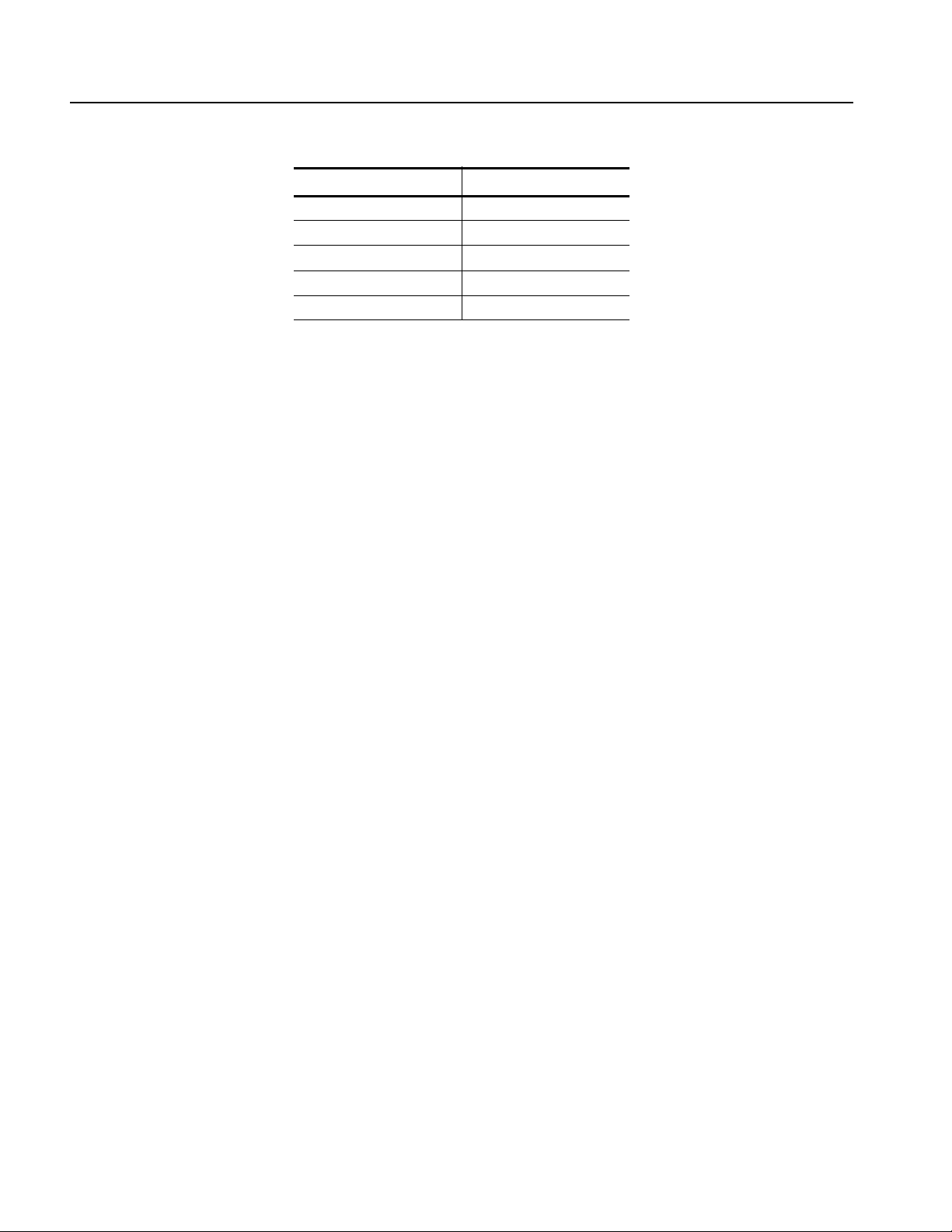
notation. Table 2-1 defines standard BNF symbols.
Table 2-1: BNF symbols and meanings
Symbol Meaning
<> Defined element
::= Is defined as
| Exclusive OR
{} Group; one element is required
[] Optional; can be omitted
. . . Previous element(s) may be repeated
() Comment
DTG5000 Series Data Timing Generators Programmer Manual 2-1

Command Syntax
SCPI Commands and Queries
The data timing generator uses a command language based on the SCPI standard.
The SCPI (Standard Commands for Programmable Instruments) standard was
created by a consortium to provide guidelines for remote programming of
instruments. These guidelines provide a consistent programming environment for
instrument control and data transfer. This environment uses defined programming
messages, instrument responses and data formats that operate across all SCPI
instruments, regardless of manufacturer.
The SCPI language is based on a hierarchical or tree structure that represents a
subsystem (see Figure 2-1). The top level of the tree is the root node; it is followed
by one or more lower–level nodes.
OUTPut
CLOCk
OFFSet
STATeAMPLitude
Root node
Lower-level
nodes
Figure 2-1: Example of SCPI subsystem hierarchy tree
You can create commands and queries from these subsystem hierarchy trees.
Commands specify actions for the instrument to perform. Queries return
measurement data and information about parameter settings.
2-2 DTG5000 Series Data Timing Generators Programmer Manual

Command Syntax
Creating Commands
Creating Queries
Query Responses
SCPI commands are created by stringing together the nodes of a subsystem
hierarchy and separating each node by a colon.
In Figure 2-1 on page 2-2, OUTPut is the root node and CLOCk, AMPLitude,
OFFSet, and STATe are lower–level nodes. To create an SCPI command, start
with the root node OUTPut and move down the tree structure adding nodes until
you reach the end of a branch. Most commands and some queries have parameters;
you must include a value for these parameters. The command descriptions, which
begin on page 2-21, list the valid values for all parameters.
For example, OUTPut:CLOCk:AMPLitude 2.0 is a valid SCPI command
created from the hierarchy tree in Figure 2-1 on page 2-2.
To create a query, start at the root node of a tree structure, move down to the end
of a branch, and add a question mark. OUTPut:CLOCk:AMPLitude? is an
example of a valid SCPI query using the hierarchy tree in Figure 2-1 on
page 2-2.
The query causes the data timing generator to return information about its status or
settings. When a query is sent to the data timing generator, only the values are
returned. When the returned value is a mnemonic, it is noted in abbreviated format,
as shown in Table 2-2.
Table 2-2: Query response examples
Query Response
SYSTem:VERSion? 1999.0
DIAGnostic:SELect? ALL
A few queries also initiate an operation action before returning information. For
example, the *CAL? query runs a calibration.
DTG5000 Series Data Timing Generators Programmer Manual 2-3

Command Syntax
Parameter Types
Parameters are indicated by angle brackets, such as <file_name>. There are several
different types of parameters, as listed in Table 2-3. The parameter type is listed
after the parameter. Some parameter types are defined specifically for the
DTG5000 series command set and some are defined by SCPI.
Table 2-3: Parameter types used in syntax descriptions
Parameter type Description Example
arbitrary block A block of data bytes #512234xxxxx...
where 5 indicates that the following 5
digits (12234) specify the length of
the data in bytes;
xxxxx... indicates the data
or
#0xxxxx...<LF><&EOI>
boolean Boolean numbers or NRf ON or ≠ 0
OFF or 0
discrete A list of specific values MIN, MAX
binary Binary numbers #B0110
octal Octal numbers #Q75, #Q3
hexadecimal
NR1
NR2
NR3
NRf
Numeric numeric Flexible decimal number that may be
string Alphanumeric characters (must be
numeric Integers 0, 1, 15, -1
numeric Decimal numbers 1.2, 3.141516, -6.5
numeric Floating point numbers 3.1415E-9, -16.1E5
numeric Flexible decimal number that may be
Hexadecimal numbers (0-9, A- F) #HAA, #H1
See NR1, NR2, NR3 examples in this
type NR1, NR2, or NR3
type NR1, NR2, NR3, or specific
value (MIN, MAX).
within quotation marks)
table
See NR1, NR2, NR3 discrete
examples in this table
“Testing 1, 2, 3”
About MIN, MAX
You can use MINimum, MAXimum keywords in addition to Numeric in the
commands with
“Numeric” parameter. You can set the minimum value or the
maximum value by the use of this keywords. You can query the minimum value or
the maximum value at that time.
2-4 DTG5000 Series Data Timing Generators Programmer Manual

Command Syntax
Special Characters
Abbreviating Commands,
Queries, and Parameters
The Line Feed (LF) character or the New Line (NL) character (ASCII 10), and all
characters in the range of ASCII 127-255 are defined as special characters. These
characters are used in arbitrary block arguments only; using these characters in
other parts of any command yields unpredictable results.
You can abbreviate most SCPI commands, queries, and parameters to an accepted
short form. This manual shows these commands as a combination of upper and
lower case letters. The upper case letters indicate the accepted short form of a
command, as shown in Figure 2-2. The accepted short form and the long form are
equivalent and request the same action of the instrument.
Long form of a
command
Accepted short form
of a command
OUTP
ut:CLOCk:AMPLitude 2.0
Minimum information needed
for accepted short form
OUTP:CLOC:AMPL 2.0
Figure 2-2: Example of abbreviating a command
DTG5000 Series Data Timing Generators Programmer Manual 2-5

Command Syntax
Chaining Commands and
Queries
You can chain several commands or queries together into a single message. To
create a chained message, first create a command or query, then add a semicolon
(;), and finally add more commands or queries and semicolons until you are done.
If the command following a semicolon is a root node, precede it with a colon (:).
Figure 2-3 illustrates a chained message consisting of several commands and
queries. The chained message should end in a command or query, not a semicolon.
Responses to any queries in your message are separated by semicolons.
:O
UTP:CLOC:AMPL 2.0;:JGEN:STAT ON;:OUTP:CL OC :OFFS?;:DIAG:SEL?
First command
The response from t his chained message might be:
Second command
Response from first query
First query
0;OUT P
Response from second query
Second query
Figure 2-3: Example of chaining commands and queries
If a command or query has the same root and lower–level nodes as the previous
command or query, you can omit these nodes. In Figure 2-4, the second command
has the same upper node (OUTP:DC) as the first command, so these nodes can be
omitted.
:OUTP:DC:LIM ON;:OUTP:DC:HLIM 2.0;:OUTP:DC:LLIM 0.1
Identical root and lower-level nodes
:OUTP:DC:LIM ON;HLIM 2.0;LLIM 0.1
First command Additional commands
(omitted the upper nodes )
Figure 2-4: Example of omitting upper and lower–level nodes in a chained message
2-6 DTG5000 Series Data Timing Generators Programmer Manual

Command Syntax
Unit and SI Prefix
If the decimal numeric argument refers to voltage, frequency, impedance, or time,
you can express it using SI units instead of using the scaled explicit point input
value format <NR3>. (SI units are units that conform to the System International
d’Unites standard.) For example, you can use the input format 200 mV or 1.0 MHz
instead of 200.0E-3 or 1.0E+6, respectively, to specify voltage or frequency.
You can omit the unit, but you must include the SI unit prefix. You can use either
upper or lowercase units.
V for voltage (V).
HZ for frequency (Hz).
OHM for impedance (ohm).
S for time (s).
DBM for power ratio
PCT for %
VPP for Peak-to-Peak Voltage (V p-p).
UIPP for Peak-to-Peak, Unit is UI (UI p-p).
UIRMS for RMS, Unit is UI (UIrms).
SPP for Peak-to-Peak, Unit is second (s p-p).
SRMS for RMS, Unit is second (srms).
V/NS for SLEW’s unit (V/ns).
In the case of angle, you can use RADian and DEGree. The default unit is RADian.
The SI prefixes, which must be included, are shown below. Note that either lower
or upper case prefixes can be used.
SI prefix * Corresponding power
EX 10
PE 10
T10
G10
MA 10
K10
M10
18
15
12
9
6
3
-3
DTG5000 Series Data Timing Generators Programmer Manual 2-7
Command Syntax
SI prefix * Corresponding power
U10
N10
P10
F10
A10
* Note that the prefix m/M indicates 10-3 when the decimal numeric argument
denotes voltage or time, but indicates 106 when it denotes frequency.
* Note that the prefix u/U is used instead of “µ”.
-6
-9
-12
-15
-18
Use mV for V, and MHz for Hz.
The SI prefixes need units.
correct: 10MHz, 10E+6Hz, 10E+6
incorrect: 10M
2-8 DTG5000 Series Data Timing Generators Programmer Manual

Command Syntax
General Rules
Here are three general rules for using SCPI commands, queries, and parameters:
You can use single (‘ ’) or double (“ ”) quotation marks for quoted strings, but
you cannot use both types of quotation marks for the same string.
correct: “This string uses quotation marks correctly.”
correct: ‘This string also uses quotation marks correctly.’
incorrect: “This string does not use quotation marks correctly.’
You can use upper case, lower case, or a mixture of both cases for all
commands, queries, and parameters.
:OUTPUT:DC:LEVEL 0,1.1V
is the same as
output:dc:level 0,1.1V
and
OUTPUT:dc:LEVEL 0,1.1V
NOTE. Literal strings (quoted) are case sensitive. For example: file names.
No embedded spaces are allowed between or within nodes.
correct: OUTPUT:DC:LEVEL 0,1.1V
incorrect: OUTPUT: DC: LEVEL 0,1.1V
DTG5000 Series Data Timing Generators Programmer Manual 2-9

Command Syntax
IEEE 488.2 Common Commands
ANSI/IEEE Standard 488.2 defines the codes, formats, protocols, and usage of
common commands and queries used on the interface between the controller and
the instruments. The data timing generator complies with this standard.
The syntax for an IEEE 488.2 common command is an asterisk (*) followed by a
command and, optionally, a space and parameter value. The syntax for an
IEEE 488.2 common query is an asterisk (*) followed by a query and a question
mark. All of the common commands and queries are included in the Syntax and
Commands section of this manual. The following are examples of common
commands:
*ESE 16
*CLS
The following are examples of common queries:
*ESR?
*IDN?
2-10 DTG5000 Series Data Timing Generators Programmer Manual
 Loading...