

Page 1

Service Manual
DTG5078 & DTG5274 & DTG5334
Data Timing Generators
071-1615-00
This document applies to firmware version 2.0.0
and above.
www.tektronix.com
Page 2

Copyright © Tektronix, Inc. All rights reserved.
Tektronix products are covered by U.S. and foreign patents, issued and pending. Information in this publication
supercedes that in all previously published material. Specifications and price change privileges reserved.
Tektronix, Inc., P.O. Box 500, Beaverton, OR 97077-0001
TEKTRONIX and TEK are registered trademarks of Tektronix, Inc.
Page 3

WARRANTY 2
Tektronix warrants that this product will be free from defects in materials and workmanship for a period of one (1)
year from the date of shipment. If any such product proves defective during this warranty period, Tektronix, at its
option, either will repair the defective product without charge for parts and labor, or will provide a replacement in
exchange for the defective product. Parts, modules and replacement products used by Tektronix for warranty work
may be new or reconditioned to like new performance. All replaced parts, modules and products become the property
of Tektronix.
In order to obtain service under this warranty, Customer must notify Tektronix of the defect before the expiration of
the warranty period and make suitable arrangements for the performance of service. Customer shall be responsible for
packaging and shipping the defective product to the service center designated by Tektronix, with shipping charges
prepaid. Tektronix shall pay for the return of the product to Customer if the shipment is to a location within the country
in which the Tektronix service center is located. Customer shall be responsible for paying all shipping charges, duties,
taxes, and any other charges for products returned to any other locations.
This warranty shall not apply to any defect, failure or damage caused by improper use or improper or inadequate
maintenance and care. Tektronix shall not be obligated to furnish service under this warranty a) to repair damage
resulting from attempts by personnel other than Tektronix representatives to install, repair or service the product; b) to
repair damage resulting from improper use or connection to incompatible equipment; c) to repair any damage or
malfunction caused by the use of non-Tektronix supplies; or d) to service a product that has been modified or integrated
with other products when the effect of such modification or integration increases the time or difficulty of servicing the
product.
THIS WARRANTY IS GIVEN BY TEKTRONIX WITH RESPECT TO THE PRODUCT IN LIEU OF ANY
OTHER WARRANTIES, EXPRESS OR IMPLIED. TEKTRONIX AND ITS VENDORS DISCLAIM ANY
IMPLIED WARRANTIES OF MERCHANTABILITY OR FITNESS FOR A PARTICULAR PURPOSE.
TEKTRONIX' RESPONSIBILITY TO REPAIR OR REPLACE DEFECTIVE PRODUCTS IS THE SOLE
AND EXCLUSIVE REMEDY PROVIDED TO THE CUSTOMER FOR BREACH OF THIS WARRANTY.
TEKTRONIX AND ITS VENDORS WILL NOT BE LIABLE FOR ANY INDIRECT, SPECIAL,
INCIDENTAL, OR CONSEQUENTIAL DAMAGES IRRESPECTIVE OF WHETHER TEKTRONIX OR
THE VENDOR HAS ADVANCE NOTICE OF THE POSSIBILITY OF SUCH DAMAGES.
Page 4

Page 5

Table of Contents
Specifications
Operating Information
General Safety Summary . . . . . . . . . . . . . . . . . . . . . . . . . . . . . . . . . . . . . . . . . . . . . . vii
Service Safety Summary . . . . . . . . . . . . . . . . . . . . . . . . . . . . . . . . . . . . . . . . . . . . . . . ix
Preface . . . . . . . . . . . . . . . . . . . . . . . . . . . . . . . . . . . . . . . . . . . . . . . . . . . . . . . . . . . . . xi
Manual Structure . . . . . . . . . . . . . . . . . . . . . . . . . . . . . . . . . . . . . . . . . . . . . . . . . . . . . . xi
Manual Conventions . . . . . . . . . . . . . . . . . . . . . . . . . . . . . . . . . . . . . . . . . . . . . . . . . . . xii
Finding Other Information. . . . . . . . . . . . . . . . . . . . . . . . . . . . . . . . . . . . . . . . . . . . . . . xii
Contacting Tektronix . . . . . . . . . . . . . . . . . . . . . . . . . . . . . . . . . . . . . . . . . . . . . . . . . . xiii
Introduction . . . . . . . . . . . . . . . . . . . . . . . . . . . . . . . . . . . . . . . . . . . . . . . . . . . . . . . . . xv
Performance Verification Procedures . . . . . . . . . . . . . . . . . . . . . . . . . . . . . . . . . . . . . . xv
Strategy for Servicing . . . . . . . . . . . . . . . . . . . . . . . . . . . . . . . . . . . . . . . . . . . . . . . . . . xv
Tektronix Service Offerings. . . . . . . . . . . . . . . . . . . . . . . . . . . . . . . . . . . . . . . . . . . . . xvi
Specifications . . . . . . . . . . . . . . . . . . . . . . . . . . . . . . . . . . . . . . . . . . . . . . . . . . . . . . . 1-1
Product Description . . . . . . . . . . . . . . . . . . . . . . . . . . . . . . . . . . . . . . . . . . . . . . . . . 2-1
Models . . . . . . . . . . . . . . . . . . . . . . . . . . . . . . . . . . . . . . . . . . . . . . . . . . . . . . . . . . . . . 2-1
Key Features. . . . . . . . . . . . . . . . . . . . . . . . . . . . . . . . . . . . . . . . . . . . . . . . . . . . . . . . . 2-1
Mainframe and Output Module Configuration . . . . . . . . . . . . . . . . . . . . . . . . . . . . . . 2-4
Product Software . . . . . . . . . . . . . . . . . . . . . . . . . . . . . . . . . . . . . . . . . . . . . . . . . . . . . 2-5
Installation . . . . . . . . . . . . . . . . . . . . . . . . . . . . . . . . . . . . . . . . . . . . . . . . . . . . . . . . . 2-7
Supplying Operating Power. . . . . . . . . . . . . . . . . . . . . . . . . . . . . . . . . . . . . . . . . . . . . 2-8
Checking the Environment Requirements . . . . . . . . . . . . . . . . . . . . . . . . . . . . . . . . . 2-10
Output Module . . . . . . . . . . . . . . . . . . . . . . . . . . . . . . . . . . . . . . . . . . . . . . . . . . . . . . 2-11
Powering On the Data Timing Generator . . . . . . . . . . . . . . . . . . . . . . . . . . . . . . . . . 2-12
Shutting Down the Data Timing Generator . . . . . . . . . . . . . . . . . . . . . . . . . . . . . . . . 2-13
Creating an Emergency Rescue Disk. . . . . . . . . . . . . . . . . . . . . . . . . . . . . . . . . . . . . 2-15
Backing Up User Files . . . . . . . . . . . . . . . . . . . . . . . . . . . . . . . . . . . . . . . . . . . . . . . . 2-17
Installing Software . . . . . . . . . . . . . . . . . . . . . . . . . . . . . . . . . . . . . . . . . . . . . . . . . . . 2-17
Operating Basics . . . . . . . . . . . . . . . . . . . . . . . . . . . . . . . . . . . . . . . . . . . . . . . . . . . 2-19
Front Panel . . . . . . . . . . . . . . . . . . . . . . . . . . . . . . . . . . . . . . . . . . . . . . . . . . . . . . . . 2-19
Front Panel Controls . . . . . . . . . . . . . . . . . . . . . . . . . . . . . . . . . . . . . . . . . . . . . . . . . 2-21
Front Panel Connectors . . . . . . . . . . . . . . . . . . . . . . . . . . . . . . . . . . . . . . . . . . . . . . . 2-24
Rear Panel Connectors. . . . . . . . . . . . . . . . . . . . . . . . . . . . . . . . . . . . . . . . . . . . . . . . 2-27
Display Area and Application Windows . . . . . . . . . . . . . . . . . . . . . . . . . . . . . . . . . . 2-32
Using the Menu System . . . . . . . . . . . . . . . . . . . . . . . . . . . . . . . . . . . . . . . . . . . . . . . 2-35
Theory of Operation
Theory of Operation . . . . . . . . . . . . . . . . . . . . . . . . . . . . . . . . . . . . . . . . . . . . . . . . . 3-1
Interconnect Diagrams . . . . . . . . . . . . . . . . . . . . . . . . . . . . . . . . . . . . . . . . . . . . . . . . . 3-1
Block Diagrams . . . . . . . . . . . . . . . . . . . . . . . . . . . . . . . . . . . . . . . . . . . . . . . . . . . . . . 3-7
DTG5078 & DTG5274 & DTG5334 Data Timing Generators Service Manual i
Page 6

Table of Contents
Performance Verification
Performance Verification . . . . . . . . . . . . . . . . . . . . . . . . . . . . . . . . . . . . . . . . . . . . . . 4-1
Adjustment Procedures
Adjustment Procedures . . . . . . . . . . . . . . . . . . . . . . . . . . . . . . . . . . . . . . . . . . . . . . . 5-1
Maintenance
Maintenance . . . . . . . . . . . . . . . . . . . . . . . . . . . . . . . . . . . . . . . . . . . . . . . . . . . . . . . . 6-1
Related Maintenance Procedures . . . . . . . . . . . . . . . . . . . . . . . . . . . . . . . . . . . . . . . . . 6-1
Preparation . . . . . . . . . . . . . . . . . . . . . . . . . . . . . . . . . . . . . . . . . . . . . . . . . . . . . . . . . . 6-2
Inspection and Cleaning . . . . . . . . . . . . . . . . . . . . . . . . . . . . . . . . . . . . . . . . . . . . . . . . 6-3
Removal and Installation Procedures . . . . . . . . . . . . . . . . . . . . . . . . . . . . . . . . . . . . 6-7
Preparation for Use . . . . . . . . . . . . . . . . . . . . . . . . . . . . . . . . . . . . . . . . . . . . . . . . . . . . 6-7
Access Procedure . . . . . . . . . . . . . . . . . . . . . . . . . . . . . . . . . . . . . . . . . . . . . . . . . . . . 6-13
Procedures for External Modules . . . . . . . . . . . . . . . . . . . . . . . . . . . . . . . . . . . . . . . . 6-14
Procedures for Internal Modules (Lower). . . . . . . . . . . . . . . . . . . . . . . . . . . . . . . . . . 6-30
Procedures for Internal Modules (Upper) . . . . . . . . . . . . . . . . . . . . . . . . . . . . . . . . . . 6-40
Troubleshooting . . . . . . . . . . . . . . . . . . . . . . . . . . . . . . . . . . . . . . . . . . . . . . . . . . . . 6-45
Troubleshooting tree . . . . . . . . . . . . . . . . . . . . . . . . . . . . . . . . . . . . . . . . . . . . . . . . . . 6-45
Diagnostics . . . . . . . . . . . . . . . . . . . . . . . . . . . . . . . . . . . . . . . . . . . . . . . . . . . . . . . . . 6-53
System Recovery . . . . . . . . . . . . . . . . . . . . . . . . . . . . . . . . . . . . . . . . . . . . . . . . . . . . 6-73
Requirements for System Recovery . . . . . . . . . . . . . . . . . . . . . . . . . . . . . . . . . . . . . . 6-73
Operating Procedure . . . . . . . . . . . . . . . . . . . . . . . . . . . . . . . . . . . . . . . . . . . . . . . . . . 6-73
Service Password . . . . . . . . . . . . . . . . . . . . . . . . . . . . . . . . . . . . . . . . . . . . . . . . . . . 6-77
Enable the Service mode. . . . . . . . . . . . . . . . . . . . . . . . . . . . . . . . . . . . . . . . . . . . . . . 6-77
Serial number registration . . . . . . . . . . . . . . . . . . . . . . . . . . . . . . . . . . . . . . . . . . . . . . 6-78
Replaceable Electrical Parts
Electrical Parts List . . . . . . . . . . . . . . . . . . . . . . . . . . . . . . . . . . . . . . . . . . . . . . . . . . 7-1
Diagrams
Diagrams . . . . . . . . . . . . . . . . . . . . . . . . . . . . . . . . . . . . . . . . . . . . . . . . . . . . . . . . . . . 8-1
Replaceable Mechanical Parts
Replaceable Mechanical Parts . . . . . . . . . . . . . . . . . . . . . . . . . . . . . . . . . . . . . . . . . 9-1
Parts Ordering Information . . . . . . . . . . . . . . . . . . . . . . . . . . . . . . . . . . . . . . . . . . . . . . 9-1
Using the Replaceable Parts List. . . . . . . . . . . . . . . . . . . . . . . . . . . . . . . . . . . . . . . . . . 9-2
ii DTG5078 & DTG5274 & DTG5334 Data Timing Generators Service Manual
Page 7

List of Figures
Table of Contents
Figure 2-1: Principal power switch and AC power connector . . . . . . . . . . . . . . 2-12
Figure 2-2: On/Standby switch location . . . . . . . . . . . . . . . . . . . . . . . . . . . . . . . . 2-12
Figure 2-3: Front panel (DTG5078) . . . . . . . . . . . . . . . . . . . . . . . . . . . . . . . . . . . 2-19
Figure 2-4: Front panel (DTG5274, DTG5334) . . . . . . . . . . . . . . . . . . . . . . . . . . 2-20
Figure 2-5: Front panel controls . . . . . . . . . . . . . . . . . . . . . . . . . . . . . . . . . . . . . . 2-21
Figure 2-6: Front panel connectors . . . . . . . . . . . . . . . . . . . . . . . . . . . . . . . . . . . . 2-24
Figure 2-7: Rear panel (DTG5078) . . . . . . . . . . . . . . . . . . . . . . . . . . . . . . . . . . . . 2-27
Figure 2-8: Rear panel connectors (1) . . . . . . . . . . . . . . . . . . . . . . . . . . . . . . . . . . 2-28
Figure 2-9: Rear panel connectors (DTG5078) (2) . . . . . . . . . . . . . . . . . . . . . . . 2-29
Figure 2-10: Screen elements just after the power on . . . . . . . . . . . . . . . . . . . . . 2-32
Figure 2-11: Toolbar . . . . . . . . . . . . . . . . . . . . . . . . . . . . . . . . . . . . . . . . . . . . . . . . 2-34
Figure 2-12: Status bar . . . . . . . . . . . . . . . . . . . . . . . . . . . . . . . . . . . . . . . . . . . . . . 2-35
Figure 2-13: Menu selection . . . . . . . . . . . . . . . . . . . . . . . . . . . . . . . . . . . . . . . . . . 2-35
Figure 2-14: Window operation: Time Base window . . . . . . . . . . . . . . . . . . . . . 2-37
Figure 3-1: DTG5078 interconnection diagram . . . . . . . . . . . . . . . . . . . . . . . . . . . 3-4
Figure 3-2: DTG5274 interconnection diagram . . . . . . . . . . . . . . . . . . . . . . . . . . . 3-5
Figure 3-3: DTG5334 interconnection diagram . . . . . . . . . . . . . . . . . . . . . . . . . . . 3-6
Figure 3-4: DTG5078 block diagram . . . . . . . . . . . . . . . . . . . . . . . . . . . . . . . . . . . 3-8
Figure 3-5: DTG5274 block diagram . . . . . . . . . . . . . . . . . . . . . . . . . . . . . . . . . . . 3-9
Figure 3-6: DTG5334 block diagram . . . . . . . . . . . . . . . . . . . . . . . . . . . . . . . . . . 3-10
Figure 6-1: Instrument orientation (DTG5078) . . . . . . . . . . . . . . . . . . . . . . . . . . . 6-9
Figure 6-2: External modules . . . . . . . . . . . . . . . . . . . . . . . . . . . . . . . . . . . . . . . . . 6-10
Figure 6-3: Front-Panel assembly & Display assembly . . . . . . . . . . . . . . . . . . . . 6-11
Figure 6-4: Internal modules (Lower) . . . . . . . . . . . . . . . . . . . . . . . . . . . . . . . . . . 6-12
Figure 6-5: Internal modules (Upper) . . . . . . . . . . . . . . . . . . . . . . . . . . . . . . . . . . 6-12
Figure 6-6: Output Module removal . . . . . . . . . . . . . . . . . . . . . . . . . . . . . . . . . . . 6-15
Figure 6-7: Modules on the rear panel . . . . . . . . . . . . . . . . . . . . . . . . . . . . . . . . . 6-16
Figure 6-8: Loosen the screws . . . . . . . . . . . . . . . . . . . . . . . . . . . . . . . . . . . . . . . . 6-16
Figure 6-9: CD-ROM module removal . . . . . . . . . . . . . . . . . . . . . . . . . . . . . . . . . 6-17
Figure 6-10: Loosen the screws . . . . . . . . . . . . . . . . . . . . . . . . . . . . . . . . . . . . . . . 6-17
Figure 6-11: Hard Disk drive removal . . . . . . . . . . . . . . . . . . . . . . . . . . . . . . . . . 6-18
Figure 6-12: Loosen the screws . . . . . . . . . . . . . . . . . . . . . . . . . . . . . . . . . . . . . . . 6-19
Figure 6-13: Cabinet removal . . . . . . . . . . . . . . . . . . . . . . . . . . . . . . . . . . . . . . . . 6-20
Figure 6-14: Remove the screws . . . . . . . . . . . . . . . . . . . . . . . . . . . . . . . . . . . . . . 6-21
Figure 6-15: Front-Panel assembly removal . . . . . . . . . . . . . . . . . . . . . . . . . . . . 6-22
Figure 6-16: Front-Panel assembly removal . . . . . . . . . . . . . . . . . . . . . . . . . . . . 6-23
Figure 6-17: FD drive removal . . . . . . . . . . . . . . . . . . . . . . . . . . . . . . . . . . . . . . . 6-23
Figure 6-18: Front-panel chassis removal . . . . . . . . . . . . . . . . . . . . . . . . . . . . . . 6-24
Figure 6-19: A20 Front Key & DC Output board removal . . . . . . . . . . . . . . . . 6-25
Figure 6-20: A22 Power Switch Board removal . . . . . . . . . . . . . . . . . . . . . . . . . . 6-26
Figure 6-21: Display assembly removal . . . . . . . . . . . . . . . . . . . . . . . . . . . . . . . . 6-27
Figure 6-22: Inverter board removal . . . . . . . . . . . . . . . . . . . . . . . . . . . . . . . . . . 6-28
Figure 6-23: Fan removal . . . . . . . . . . . . . . . . . . . . . . . . . . . . . . . . . . . . . . . . . . . . 6-29
Figure 6-24: Support bracket removal . . . . . . . . . . . . . . . . . . . . . . . . . . . . . . . . . 6-30
Figure 6-25: Unplug the cables and connectors (DTG5078) . . . . . . . . . . . . . . . . 6-31
Figure 6-26: Unplug the cables and connectors (DTG5274) . . . . . . . . . . . . . . . . 6-32
DTG5078 & DTG5274 & DTG5334 Data Timing Generators Service Manual iii
Page 8

Table of Contents
Figure 6-27: Unplug the cables and connectors (DTG5334) . . . . . . . . . . . . . . . . 6-33
Figure 6-28: Plug-In Box removal (DTG5078 & DTG5274) . . . . . . . . . . . . . . . . 6-34
Figure 6-29: Plug-In Box removal (DTG5334) . . . . . . . . . . . . . . . . . . . . . . . . . . . 6-35
Figure 6-30: Unplug the cables and connectors . . . . . . . . . . . . . . . . . . . . . . . . . . . 6-36
Figure 6-31: 16 screws . . . . . . . . . . . . . . . . . . . . . . . . . . . . . . . . . . . . . . . . . . . . . . . 6-38
Figure 6-32: Power supply removal . . . . . . . . . . . . . . . . . . . . . . . . . . . . . . . . . . . . 6-40
Figure 6-33: A10 Connector & PCI Interface board removal . . . . . . . . . . . . . . . 6-41
Figure 6-34: A10 Connector & PCI Interface board removal . . . . . . . . . . . . . . . 6-42
Figure 6-35: Compact PCI Frame removal . . . . . . . . . . . . . . . . . . . . . . . . . . . . . . 6-43
Figure 6-36: A30 Compact PCI Backplane removal . . . . . . . . . . . . . . . . . . . . . . . 6-44
Figure 6-37: Primary troubleshooting procedure (1) . . . . . . . . . . . . . . . . . . . . . . 6-46
Figure 6-38: Primary troubleshooting procedure (2) . . . . . . . . . . . . . . . . . . . . . . 6-47
Figure 6-39: Primary troubleshooting procedure (3) . . . . . . . . . . . . . . . . . . . . . . 6-48
Figure 6-40: Troubleshooting procedure B - Display section . . . . . . . . . . . . . . . 6-48
Figure 6-41: Troubleshooting procedure A - Power Supply and
A10 board section . . . . . . . . . . . . . . . . . . . . . . . . . . . . . . . . . . . . . . . 6-49
Figure 6-42: Test point on the A10 Connector board . . . . . . . . . . . . . . . . . . . . . . 6-50
Figure 6-43: Diagnostics dialog box . . . . . . . . . . . . . . . . . . . . . . . . . . . . . . . . . . . . 6-54
Figure 6-44: Diagnostics error code format . . . . . . . . . . . . . . . . . . . . . . . . . . . . . . 6-58
Figure 6-45: Service Password dialog box . . . . . . . . . . . . . . . . . . . . . . . . . . . . . . . 6-77
Figure 6-46: Set Serial Number dialog box . . . . . . . . . . . . . . . . . . . . . . . . . . . . . . 6-78
Figure 9-1: Main Chassis (1) (DTG5078) . . . . . . . . . . . . . . . . . . . . . . . . . . . . . . . . . 9-5
Figure 9-2: Main Chassis (1) (DTG5274) . . . . . . . . . . . . . . . . . . . . . . . . . . . . . . . . . 9-7
Figure 9-3: Main Chassis (1) (DTG5334) . . . . . . . . . . . . . . . . . . . . . . . . . . . . . . . . . 9-9
Figure 9-4: Main Chassis (2) . . . . . . . . . . . . . . . . . . . . . . . . . . . . . . . . . . . . . . . . . 9-11
Figure 9-5: Main Chassis & Cabinet . . . . . . . . . . . . . . . . . . . . . . . . . . . . . . . . . . . 9-12
Figure 9-6: A30 & Compact PCI Frame . . . . . . . . . . . . . . . . . . . . . . . . . . . . . . . . 9-13
Figure 9-7: Power Supply . . . . . . . . . . . . . . . . . . . . . . . . . . . . . . . . . . . . . . . . . . . . 9-15
Figure 9-8: Floppy Disk Drive . . . . . . . . . . . . . . . . . . . . . . . . . . . . . . . . . . . . . . . . . 9-16
Figure 9-9: A10 Connector & PCI Interface . . . . . . . . . . . . . . . . . . . . . . . . . . . . . 9-17
Figure 9-10: A32 CDROM Extender . . . . . . . . . . . . . . . . . . . . . . . . . . . . . . . . . . . 9-18
Figure 9-11: CPU Unit . . . . . . . . . . . . . . . . . . . . . . . . . . . . . . . . . . . . . . . . . . . . . . . 9-19
Figure 9-12: Front Panel (DTG5078) . . . . . . . . . . . . . . . . . . . . . . . . . . . . . . . . . . . 9-21
Figure 9-13: Front Panel (DTG5274) . . . . . . . . . . . . . . . . . . . . . . . . . . . . . . . . . . . 9-23
Figure 9-14: Front Panel (DTG5334) . . . . . . . . . . . . . . . . . . . . . . . . . . . . . . . . . . . 9-25
Figure 9-15: Cabinet . . . . . . . . . . . . . . . . . . . . . . . . . . . . . . . . . . . . . . . . . . . . . . . . 9-27
Figure 9-16: Plug-In Box (DTG5078) . . . . . . . . . . . . . . . . . . . . . . . . . . . . . . . . . . . 9-28
Figure 9-17: Plug-In Box (DTG5274) . . . . . . . . . . . . . . . . . . . . . . . . . . . . . . . . . . . 9-29
Figure 9-18: Plug-In Box (DTG5334) . . . . . . . . . . . . . . . . . . . . . . . . . . . . . . . . . . . 9-30
Figure 9-19: Blank Plug-In . . . . . . . . . . . . . . . . . . . . . . . . . . . . . . . . . . . . . . . . . . . 9-31
Figure 9-20: DTGM10 . . . . . . . . . . . . . . . . . . . . . . . . . . . . . . . . . . . . . . . . . . . . . . . 9-33
Figure 9-21: DTGM20 . . . . . . . . . . . . . . . . . . . . . . . . . . . . . . . . . . . . . . . . . . . . . . . 9-35
Figure 9-22: DTGM21 . . . . . . . . . . . . . . . . . . . . . . . . . . . . . . . . . . . . . . . . . . . . . . . 9-37
Figure 9-23: DTGM30 . . . . . . . . . . . . . . . . . . . . . . . . . . . . . . . . . . . . . . . . . . . . . . . 9-39
Figure 9-24: DTGM31 . . . . . . . . . . . . . . . . . . . . . . . . . . . . . . . . . . . . . . . . . . . . . . . 9-41
Figure 9-25: DTGM32 . . . . . . . . . . . . . . . . . . . . . . . . . . . . . . . . . . . . . . . . . . . . . . . 9-43
Figure 9-26: Op 1R (Rack Mount) . . . . . . . . . . . . . . . . . . . . . . . . . . . . . . . . . . . . . 9-44
iv DTG5078 & DTG5274 & DTG5334 Data Timing Generators Service Manual
Page 9

List of Tables
Table of Contents
Table 2-1: DTG5000 series key features . . . . . . . . . . . . . . . . . . . . . . . . . . . . . . . . . 2-2
Table 2-2: DTG5000 series Output module key features . . . . . . . . . . . . . . . . . . . 2-3
Table 2-3: Current consumption coefficient . . . . . . . . . . . . . . . . . . . . . . . . . . . . . . 2-4
Table 2-4: Power cord identification . . . . . . . . . . . . . . . . . . . . . . . . . . . . . . . . . . . . 2-9
Table 2-5: Operating requirements . . . . . . . . . . . . . . . . . . . . . . . . . . . . . . . . . . . . 2-10
Table 2-6: Front panel controls . . . . . . . . . . . . . . . . . . . . . . . . . . . . . . . . . . . . . . . 2-21
Table 2-7: Front panel connectors . . . . . . . . . . . . . . . . . . . . . . . . . . . . . . . . . . . . . 2-24
Table 2-8: Rear panel connector (1) . . . . . . . . . . . . . . . . . . . . . . . . . . . . . . . . . . . 2-28
Table 2-9: Rear panel connectors (2) . . . . . . . . . . . . . . . . . . . . . . . . . . . . . . . . . . 2-29
Table 2-10: Menu selection . . . . . . . . . . . . . . . . . . . . . . . . . . . . . . . . . . . . . . . . . . . 2-36
Table 2-11: Time Base Window operation . . . . . . . . . . . . . . . . . . . . . . . . . . . . . . 2-37
Table 2-12: Example of Numeric Keys input . . . . . . . . . . . . . . . . . . . . . . . . . . . . 2-38
Table 2-13: Example of Numeric Keys input . . . . . . . . . . . . . . . . . . . . . . . . . . . . 2-39
Table 2-14: Selecting a file . . . . . . . . . . . . . . . . . . . . . . . . . . . . . . . . . . . . . . . . . . . 2-40
Table 2-15: Key operations . . . . . . . . . . . . . . . . . . . . . . . . . . . . . . . . . . . . . . . . . . 2-41
Table 6-1: External inspection check list . . . . . . . . . . . . . . . . . . . . . . . . . . . . . . . . 6-4
Table 6-2: Internal inspection check list . . . . . . . . . . . . . . . . . . . . . . . . . . . . . . . . . 6-5
Table 6-3: Tools required for module removal . . . . . . . . . . . . . . . . . . . . . . . . . . . 6-8
Table 6-4: Performance Test . . . . . . . . . . . . . . . . . . . . . . . . . . . . . . . . . . . . . . . . . 6-51
Table 6-5: Diagnostics dialog box buttons . . . . . . . . . . . . . . . . . . . . . . . . . . . . . . 6-54
Table 6-6: Information on Status . . . . . . . . . . . . . . . . . . . . . . . . . . . . . . . . . . . . . 6-57
Table 6-7: Category of the Diagnostics Error Code . . . . . . . . . . . . . . . . . . . . . . 6-59
Table 6-8: Error Codes . . . . . . . . . . . . . . . . . . . . . . . . . . . . . . . . . . . . . . . . . . . . . . 6-60
DTG5078 & DTG5274 & DTG5334 Data Timing Generators Service Manual v
Page 10

Table of Contents
vi DTG5078 & DTG5274 & DTG5334 Data Timing Generators Service Manual
Page 11

General Safety Summary
Review the following safety precautions to avoid injury and prevent damage to this
product or any products connected to it. To avoid potential hazards, use this
product only as specified.
Only qualified personnel should perform service procedures.
To Avoid Fire or
Personal Injury
Use Proper Power Cord. Use only the power cord specified for this product and
certified for the country of use.
Ground the Product. This product is grounded through the grounding conductor of
the power cord. To avoid electric shock, the grounding conductor must be
connected to earth ground. Before making connections to the input or output
terminals of the product, ensure that the product is properly grounded.
Observe All Terminal Ratings. To avoid fire or shock hazard, observe all ratings and
markings on the product. Consult the product manual for further ratings
information before making connections to the product.
The common terminal is at ground potential. Do not connect the common terminal
to elevated voltages.
Do not apply a potential to any terminal, including the common terminal, that
exceeds the maximum rating of that terminal.
Do Not Operate Without Covers. Do not operate this product with covers or panels
removed.
Avoid Exposed Circuitry. Do not touch exposed connections and components when
power is present.
Do Not Operate With Suspected Failures. If you suspect there is damage to this
product, have it inspected by qualified service personnel.
Do Not Operate in Wet/Damp Conditions.
Do Not Operate in an Explosive Atmosphere.
Keep Product Surfaces Clean and Dry.
Provide Proper Ventilation. Refer to the manual’s installation instructions for
details on installing the product so it has proper ventilation.
DTG5078 & DTG5274 & DTG5334 Data Timing Generators Service Manual vii
Page 12

General Safety Summary
Symbols and Terms
Terms in this Manual. These terms may appear in this manual:
WARNING. Warning statements identify conditions or practices that could result in
injury or loss of life.
CAUTION. Caution statements identify conditions or practices that could result in
damage to this product or other property.
Terms on the Product. These terms may appear on the product:
DANGER indicates an injury hazard immediately accessible as you read the
marking.
WARNING indicates an injury hazard not immediately accessible as you read the
marking.
CAUTION indicates a hazard to property including the product.
Symbols on the Product. The following symbols may appear on the product:
WAR NING
High Voltage
Protective Ground
(Earth) Terminal
CAUTION
Refer to Manual
Double
Insulated
viii DTG5078 & DTG5274 & DTG5334 Data Timing Generators Service Manual
Page 13

Service Safety Summary
DTG5000 Series only qualified personnel should perform service procedures.
Read this Service Safety Summary and the General Safety Summary before
performing any service procedures.
Do Not Service Alone. Do not perform internal service or adjustments of this
product unless another person capable of rendering first aid and resuscitation is
present.
Disconnect Power. To avoid electric shock, disconnect the mains power by means
of the power cord or, if provided, the power switch.
Use Care When Servicing With Power On. Dangerous voltages or currents may exist
in this product. Disconnect power, remove battery (if applicable), and disconnect
test leads before removing protective panels, soldering, or replacing components.
To avoid electric shock, do not touch exposed connections.
Calendar (date and time) Backup Battery. This product contains a
Lithium:poly-carbon mono fluoride battery for calendar backup purposes. This
battery is part of the CPU unit and is not replaceable.
DTG5078 & DTG5274 & DTG5334 Data Timing Generators Service Manual ix
Page 14

Service Safety Summary
x DTG5078 & DTG5274 & DTG5334 Data Timing Generators Service Manual
Page 15

Preface
Manual Structure
This manual provides information necessary for service technicians to service the
DTG5000 Series Data Timing Generator to the module level.
This manual is divided into sections, such as Specifications and Theory of
Operation. Further, some sections are divided into subsections, such as Product
Description and Removal and Installation Procedures.
Sections containing procedures also contain introductions to those procedures. Be
sure to read these introductions because they provide information needed to do the
service correctly and efficiently. The following contains a brief description of each
manual section.
Operating Information includes general information and operating
instructions.
Theory of Operation contains circuit descriptions that support service to the
module level.
Adjustment Procedures contains information that you need to manually adjust
the data timing generator so that it meets specifications.
Maintenance contains information and procedures for performing preventive
and corrective maintenance of the data timing generator. These instructions
include cleaning, module removal and installation, and fault isolation to the
module.
Replaceable Electrical Parts contains a statement referring you to Replaceable
Mechanical Parts, where both electrical and mechanical modules are listed.
Diagrams contains block diagrams and an interconnection diagram.
Replaceable Mechanical Parts includes a table of all replaceable modules,
their descriptions, and their Tektronix part numbers.
DTG5078 & DTG5274 & DTG5334 Data Timing Generators Service Manual xi
Page 16

Preface
Manual Conventions
This manual uses certain conventions that you should become familiar with.
Some sections of the manual contain procedures for you to perform. To keep those
instructions clear and consistent, this manual uses the following conventions:
Front-panel controls and menu names appear in the same case (initial capitals,
all uppercase, and so on) in the manual as is used on the data timing generator
front-panel and menus. Front-panel labels are all upper case letters (for
example, MENU, SELECT, PULSE GEN, and so on).
Instruction steps are numbered unless there is only one step.
Modules
Throughout this manual, any replaceable component, assembly, or part of the data
timing generator is referred to generically as a module. In general, a module is an
assembly (like a circuit board), rather than a component (like a resistor or an
integrated circuit). Sometimes a single component is a module; for example, the
chassis of the data timing generator is a module.
Safety
Symbols and terms related to safety appear in the Safety Summary near the
beginning of this manual.
Finding Other Information
This manual mainly focuses on the troubleshooting and maintenance of the data
timing generator. See the following list for other documents supporting the data
timing generator operation. All documents are on the DTG5000 Series Product
Documents CD-ROM that shipped with instrument.
Document name Description
DTG5000 Series Technical Reference for
Performance Verification & Specifications
DTG5000 Series User Manual 1 A quick reference to major features of the instrument and how they operate. It also provides
DTG5000 Series User Manual 2 A reference provides an encyclopedia of topics that describe the data timing generator
DTG5000 Series Programmer Manual Provides complete information on programming commands and remote control of the
DTG5000 Series Online Help An online help system, integrated with the User Interface application that ships with this
Describes how to verify the performance of the data timing generator and lists its
specifications. (Product Documents CD)
several tutorials to familiarize the user with basic instrument features. (Product Documents
CD)
interface and features, and gives background information on how to use them. (Product
Documents CD)
instrument. (Product Documents CD)
product. The help is preinstalled in the instrument.
xii DTG5078 & DTG5274 & DTG5334 Data Timing Generators Service Manual
Page 17

Contacting Tektronix
Preface
Phone 1-800-833-9200*
Address Tektronix, Inc.
Department or name (if known)
14200 SW Karl Braun Drive
P.O. Box 500
Beaverton, OR 97077
USA
Web site www.tektronix.com
Sales support 1-800-833-9200, select option 1
Service support 1-800-833-9200, select option 2*
Technical support Email: techsupport@tektronix.com
1-800-833-9200, select option 3
6:00 a.m. - 5:00 p.m. Pacific time
* This phone number is toll free in North America. After office hours, please leave
a voice mail message.
Outside North America, contact a Tektronix sales office or distributor; see the
Tektronix web site for a list of offices.
*
*
DTG5078 & DTG5274 & DTG5334 Data Timing Generators Service Manual xiii
Page 18

Preface
xiv DTG5078 & DTG5274 & DTG5334 Data Timing Generators Service Manual
Page 19

Introduction
This manual contains information that is needed to properly service the DTG5000
Series Data Timing Generator as well as general information that is critical to safe
and effective servicing.
To prevent personal injury or damage to the data timing generator, consider the
following before attempting service:
The procedures in this manual should be performed only by a qualified service
person.
Read the General Safety Summary on page vii and the Service Safety Summary,
beginning on page ix.
Read Installation in Operating Information.
When using this manual for servicing, be sure to follow all warnings, cautions, and
notes.
Performance Verification Procedures
Strategy for Servicing
The performance check should be done every 12 months. In addition, a
performance check is recommended after module replacement. The performance
check procedures for this instrument are on the DTG5000 Series Product
Documents CD-ROM (Tektronix part number 063-3883-xx) that shipped with
your product. Look for the DTG5000 Series Technical Reference for Performance
Verification & Specifications PDF on this disk.
If the data timing generator does not meet performance criteria, repair is necessary.
Throughout this manual, the term, module, refers to any field-replaceable
component, assembly, or part of the data timing generator.
This manual contains the information needed for periodic maintenance of the data
timing generator. Further, it contains information for corrective maintenance down
to the module level. To isolate a failure to a module, use the troubleshooting
procedures found in the Maintenance section. To remove and replace any failed
module, follow the instructions in the Removal and Installation Procedures
subsection. After isolating a faulty module, replace it with a fully-tested module
obtained from the factory. The Replaceable Mechanical Parts section contains part
number and ordering information for all replaceable modules.
DTG5078 & DTG5274 & DTG5334 Data Timing Generators Service Manual xv
Page 20

Introduction
Tektronix Service Offerings
Tektronix provides service to cover repair under warranty as well as other services
that may provide a cost-effective answer to your service needs.
Whether providing warranty repair service or any of the other services listed
below, Tektronix service technicians are well trained to service the data timing
generator. They have access to the latest information on improvements to the
DTG5000 Series as well as new options.
Warranty Repair Service
Self Service
Tektronix warrants this product for one year from date of purchase. The warranty
appears at the front of this manual. Tektronix technicians provide warranty service
at most Tektronix service locations. The Tektronix product catalog lists all
worldwide service locations.
Tektronix supports repair to the module level by providing Module Exchange.
Module Exchange. This service reduces down-time for repair by allowing you to
exchange most modules for remanufactured ones. Each module comes with a
90-day service warranty.
For More Information. Contact your local Tektronix service center or sales engineer
for more information on any of the repair or adjustment services just described.
xvi DTG5078 & DTG5274 & DTG5334 Data Timing Generators Service Manual
Page 21

Specifications
Page 22

Page 23

Specifications
The specifications for this instrument are now available on the DTG5078 &
DTG5274 & DTG5334 Performance Verification & Specifications Technical
Reference (Tektronix part number 071-1611-xx). A PDF of this technical reference
is provided on the DTG5000 Series Product Documents CD-ROM (Tektronix part
number 063-3833-xx) that shipped with your product.
DTG5078 & DTG5274 & DTG5334 Data Timing Generators Service Manual 1-1
Page 24

Specifications
1-2 DTG5078 & DTG5274 & DTG5334 Data Timing Generators Service Manual
Page 25

Operating Information
Page 26

Page 27

Product Description
This section describes the key features of the DTG5000 Series Data Timing
Generators and their Output modules.
Models
This manual supports the following data timing generators:
DTG5078 Data Timing Generator
DTG5274 Data Timing Generator
DTG5334 Data Timing Generator
The differences between the data timing generators will be called out when
necessary; otherwise, the material applies to all data timing generators. The term
“data timing generator” refers to all of the products.
Key Features
The DTG5000 Series Data Timing Generator is a high-speed, multichannel signal
generator that creates a wide range of digital timing signals. The products are
designed to generate a data pattern for standard and nonstandard pulses necessary
for functional tests or characterization of legacy devices (TTL, CMOS, ECL) as
well as the latest devices (PECL, LVDS, GTL, CML).
Use the DTG5000 series to insert glitches and jitter as needed, and easily create
patterns for device stress testing. In addition, to shorten testing time, use the
sequence function to create signal sequences from combinations of various
patterns.
The DTG5000 Series Data Timing Generator supports six types of output modules
(DTGM10, DTGM20, DTGM21, DTGM30, DTGM31 and DTGM32). Table 2-1
lists the key features of the data timing generators, and Table 2-2 lists the key
features of the output modules.
DTG5078 & DTG5274 & DTG5334 Data Timing Generators Service Manual 2-1
Page 28

Product Description
Table 2-1: DTG5000 series key features
DTG5078 DTG5274 DTG5334
Maximum clock
frequency/Maximum data rate
Number of slots 8 (A, B, C, D, E, F, G, and H) 4 (A, B, C, and D) 4 (A, B, C, and D)
Pattern length 240 to 8,000,000 words/channel 960 to 32,000,000 words/channel 960 to 64,000,000 words/channel
Block size
granularity
Sequence steps 1 to 8,000 steps 1 to 8,000 steps 1 to 8,000 steps
Sequence
repeat counter
Master-Slave Up to three (one Master, two Slaves) Up to two (one Master, one Slave) Up to two (one Master, one Slave)
Data Generator
Mode
Data format
Slot A to D NRZ, RZ, and R1 NRZ, RZ, and R1 NRZ, RZ, and R1
Slot E to H NRZ
Data rate
RZ and R1 50 kb/s to 375 Mb/s 50 kb/s to 1.35 Gb/s 50 kb/s to 1.675 Gb/s
Channel addition Slot A, B, C, and D Slot A, B, C, and D Slot A, B, C, and D
Jitter generation Channel 1 of slot A Channel 1 of slot A Channel 1 of slot A
Lead delay
resolution
Trail delay
resolution
Pulse width
resolution
Pulse Generator
Mode
Clock frequency 50 kHz to 375 MHz 50 kHz to 1.35 GHz 50 kHz to 1.675 GHz
750 MHz/750 Mb/s 2.7 GHz /2.7 Gb/s 3.35 GHz /3.35 Gb/s
1 1 to 4 (depends on Vector Rate) 1 to 4 (depends on Vector Rate)
1 to 65,536 or Infinite 1 to 65,536 or Infinite 1 to 65,536 or Infinite
Slot A, B, C, D, E, F, G, and H Slot A, B, C, and D Slot A, B, C, and D
NRZ 50 kb/s to 750 Mb/s 50 kb/s to 2.7 Gb/s 50 kb/s to 3.35 Gb/s
1 ps 0.2 ps 0.2 ps
5 ps 5 ps 5 ps
5 ps (slot A, B, C, and D) 5 ps (slot A, B, C, and D) 5 ps (slot A, B, C, and D)
Slot A, B, C, and D Slot A, B, C, and D Slot A, B, C, and D
2-2 DTG5078 & DTG5274 & DTG5334 Data Timing Generators Service Manual
Page 29

Product Description
Table 2-2: DTG5000 series Output module key features
DTGM10 DTGM20 DTGM21 DTGM30 DTGM31 DTGM32
Number of channels 444211
Number of
available channels
DTG5078444211
DTG5274 2 (CH1, CH2) 2 (CH1, CH2) 2 (CH1, CH2) 2 1 1
DTG5334 2 (CH1, CH2) 2 (CH1, CH2) 2 (CH1, CH2) 2 1 1
Amplitude (50 Ω) 3.5 V
Amplitude
10 V
p-p
p-p
3.5 V
7 V
p-p
p-p
(1 MΩ)
Rise time/ fall
time at 1 V
p-p
into
<540 ps
(variable)
<340 ps
(variable)
50 Ω
(20% to 80%)
Hi Z Control yes
External Jitter
Input
3.90 V
5.35 V
7.81 V
p-p
p-p
p-p
(50 Ω)
(23 Ω)
1.25 V
2.5 V
p-p
p-p
1.25 V
2.5 V
p-p
p-p
1.25 V
2.5 V
p-p
<350 ps <110 ps <110 ps <110 ps
yes
one Input
yes
two Inputs
p-p
DTG5078 & DTG5274 & DTG5334 Data Timing Generators Service Manual 2-3
Page 30

Product Description
Mainframe and Output Module Configuration
The DTG5000 Series Data Timing Generator offers a modular card system. Six
types of the output modules can be combined in any combination. Each module can
be inserted into any slot. The functional restrictions are:
8 slots installed in the DTG5078 (A, B, C, D, E, F, G, and H)
4 slots installed in the DTG5274 and DTG5334 (A, B, C, and D)
When a DTGM10, DTGM20, or DTGM21 is installed in a DTG5274 or
DTG5334, CH3 and CH4 are unavailable. Only CH1 and CH2 can be used.
Slots E, F, G, and H are unavailable in the Pulse Generator mode.
Available data formats are different:
NRZ, RZ, R1 (Slot A, B, C, and D)
NRZ (Slot E, F, G, and H)
Due to power consumption constraints, the output modules used with the
DTG5078 are limited as follows:
Using the power consumption figures for each installed output module
[P(Mxx) in Table 2-3], the sum of all P(Mxx) values must not exceed 100.
Table 2-3: Current consumption coefficient
Module Current consumption coefficient
DTGM10 P(M10) = 9
DTGM20 P(M20) = 10
DTGM21 P(M21) = 10
DTGM30 P(M30) = 8
DTGM31 P(M31) = 33
DTGM32 P(M32) = 32
Example 1: DTGM31 1 each, DTGM30 7 each
P(M31) + P(M30) x 7 = 33 + 8 x 7 = 89 < 100; Acceptable
Example 2: DTGM32 3 each, DTGM30 5 each
P(M32) x 3 + P(M30) x 5 = 32 x 3 + 8 x 5 = 136 >100; Not Acceptable
2-4 DTG5078 & DTG5274 & DTG5334 Data Timing Generators Service Manual
Page 31

Product Software
Product Description
The data timing generator includes the following software:
The system software, which includes a specially configured version of
Windows 2000, comes preinstalled on the data timing generator. Windows
2000 is the operating system on which the user-interface application of this
product runs, and provides an open desktop for you to install other compatible
applications.
NOTE. Do not attempt to substitute any version of Windows that is not specifically
provided by Tektronix for use with this instrument.
The DTG5000 Software comes preinstalled on the data timing generator. This
software, which runs on Windows 2000, is the data timing generator
application. This software starts automatically when the data timing generator
is powered on, and provides the user interface (UI) and all other instrument
control functions. You can also minimize the data timing generator
application.
The product software runs not only on a data timing generator mainframe,
but also on a PC. When the software runs on the data timing generator
mainframe, it is called the Online mode. While running on the PC, it is
called the Offline mode. In the Offline mode, it is possible to create and edit
the pattern data and set the output parameters.
The DTG5000 Configuration Utility comes preinstalled on the data timing
generator. This software, running on Windows 2000, is used for setting up the
system configurations for the DTG5000 Software. This software controls the
Master operation, Master/Slave operation, Online/Offline operation, and so
forth.
NOTE. When you use the DTG5000 software in the offline mode, you must also
install the DTG5000 Configuration Utility into your PC.
The Readme file contains release notes and updates that could not be included
in other product documentation.
There are no limits on the number of PCs that can operate in the offline mode.
Occasionally new versions of software for your instrument may become available
on our Web site. See Contacting Tektronix on page xiii in the Preface section for
Web site information.
DTG5078 & DTG5274 & DTG5334 Data Timing Generators Service Manual 2-5
Page 32

Product Description
2-6 DTG5078 & DTG5274 & DTG5334 Data Timing Generators Service Manual
Page 33

Installation
This section covers installation of the data timing generator, addressing the
following topics:
Checking the Environment Requirements on page 2-10
Output Module on page 2-11
Powering On the Data Timing Generator on page 2-12
Shutting Down the Data Timing Generator on page 2-13
Creating an Emergency Rescue Disk on page 2-15
Backing Up User Files on page 2-17
Installing Software on page 2-17
CAUTION. Be sure to create your emergency rescue disk as described on
page 2-15. You may need that disk if you ever need to reinstall Windows 2000 from
the data timing generator hard drive.
DTG5078 & DTG5274 & DTG5334 Data Timing Generators Service Manual 2-7
Page 34

Installation
Supplying Operating Power
WARNING. To avoid equipment failure and potential fire or personal shock
hazards, do not exceed the maximum rated operating voltage of 250 V between the
voltage-to-ground (earth) and either pole of the power source. The DTG5000
Series operates from a single-phase power source and has a three-wire power cord
with a two-pole, three-terminal grounding plug. Before connecting to the power
source, be sure the DTG5000 Series has a suitable two-pole, three-terminal,
grounding-type plug.
To avoid personal shock hazard, do not touch conductive parts. All accessible
conductive parts are directly connected through the grounding conductor of the
power cord to the grounded (earth) contact of the power plug. The DTG5000 Series
is safety Class 1 equipment (IEC designation).
To prevent electrical shock, remove all power from the instrument, switch the
PRINCIPAL POWER SWITCH on the back panel to OFF, and disconnect the
power cord from the instrument. Some components in the DTG5000 Series are still
connected to line voltage after powering off the instrument from the front-panel
ON/STBY button.
Power Cord Information
A power cord with the appropriate plug configuration is supplied with each
DTG5000 Series Data Timing Generator. If you require a power cord other than
the one supplied, refer to Table 2-4
2-8 DTG5078 & DTG5274 & DTG5334 Data Timing Generators Service Manual
Page 35

Installation
Table 2-4: Power cord identification
Plug configuration Normal usage Option number
North America
125 V/15 A Plug
NEMA 5-15P
Standard
Europe
230 V
United Kingdom
230 V
Australia
230 V
Switzerland
230 V
Japan
100 V
A1
A2
A3
A5
A6
China
230 V
No power cord supplied. A99
A10
DTG5078 & DTG5274 & DTG5334 Data Timing Generators Service Manual 2-9
Page 36

Installation
Checking the Environment Requirements
Read this section before attempting any installation procedures. This section
describes site considerations and power requirements for your data timing
generator.
Site Considerations
Operating Requirements
The data timing generator is designed to operate on a bench in the normal position
(on the bottom feet). For proper cooling, at least three inches (7.62 cm) of clearance
is required on both sides of the data timing generator, and the bottom requires the
clearance provided by the bottom feet.
If you operate the data timing generator in the Master-Slave mode, you can stack
up to two mainframes.
CAUTION. To avoid damage to the mainframe, always close the bottom stands
when you stack the mainframes.
Using a cart is not recommended when you stack the mainframes. Doing so could
result in serious damage to the cart or mainframes.
Do not operate the mainframe while it rests on its left side feet. Always place the
mainframe in the normal position (on the bottom feet) while the mainframe
powered on.
Table 2-5 shows general operating requirements for the data timing generator. For
more information, refer to Specifications section in the DTG5078 & DTG5274 &
DTG5334 Performance Verification & Specifications Technical Reference. It
covers power source, temperature, humidity and altitude information.
Table 2-5: Operating requirements
Item Description
Operating temperature +10 °C to +40 °C
Operating relative humidity 20% to 80% (No condensation)
Operating altitude Up to 3 km (10,000 ft)
Power supply
Rating voltage 100 V to 240 V
Voltage range 90 V to 250 V
Frequency 47 Hz to 63 Hz
Maximum power 600 VA maximum
2-10 DTG5078 & DTG5274 & DTG5334 Data Timing Generators Service Manual
Page 37

Output Module
Installation
The DTG5000 Series Data Timing Generator mainframe and output module(s) are
shipped separately. At least one output module must be installed in the mainframe
slot to operate properly.
Six types of output modules can be combined in any combination. Each module
can be inserted in any slot. There are functional differences between slot A to D
and slot E to H. (Refer to Mainframe and Output Module Configuration on page
2-4.) It is recommended that slot A is used when only one output module is
installed in the mainframe slot.
Installing the Output
Module
To install the output module, first power off the mainframe using the front panel
On/Standby switch.
CAUTION. To prevent damage to the output module or mainframe, never install or
remove the output module when the mainframe is powered on.
To avoid damage from Electro Static Discharge, please do not touch the board
surface or connectors of the output module with your fingers when you handle the
module.
Attach the blank panel to the mainframe module slot(s) when the output module(s)
are not installed.
If the output module is not in use for a long time, attach the connector caps and
SMA terminations (DTGM30) to the output module and then store the output
module in the shipping carton. The connector caps and SMA terminations are
provided with your output module.
1. Verify that the data timing generator mainframe is not powered on.
2. Remove the blank panel from the mainframe slot.
3. Place the output module in a compartment.
4. Gently push the output module into the slot with firm pressure.
5. Once the module is seated, tighten the two screws with a screwdriver to secure
the module to the mainframe.
Removing the Output
Verify that the data timing generator mainframe is not powered on.
Module
1. Loosen the two screws.
2. Grasp the right and left screws and slowly pull the module out of the
mainframe slot.
3. Attach a blank panel to the slot.
DTG5078 & DTG5274 & DTG5334 Data Timing Generators Service Manual 2-11
Page 38

Installation
Powering On the Data Timing Generator
Follow these steps to power on the data timing generator.
1. Connect the proper power cord from the rear panel power connector to the
power system.
PRINCIPAL
Principal
power
Switch
AC power
connector
POWER SWITCH
1
AC INPUT
ONOFF
+
'44
*&&
470
.#0
8)#
+06456
5%5+
%1/
-';$1#4& /175'
CLOCK
153535
0.4Vpk-pk MIN
Vpk-
2
OUTEXTERNAL IN
-2V
TO 7
V
FROM 50˴
pk MAX
OUT
-2V
TO 7
V
FROM 50˴
MASTER/SLAVE CONNECTION
CLKIN CLK OUT 1JUMPIN JUMP OUT 2 CLKOUT 2 CLKOUT 3
CLKINJUMPOUT 1 JUMPOUT 3 CLKOUT 1 CLK OUT2 CLK OUT 3
FORMASTER/SLAVE OPERATION ONLY
PHASE LOCK
EXTERNAL
10MHz REF IN
0.2Vpk-pk MIN
Vpk-
pk MAX
3
10MHz REF OUT
2.4Vpk-pk
FROM 50˴
PHASE
LOCKIN
0.2Vpk-pk MIN
Vpk-
3
pk MAX
Figure 2-1: Principal power switch and AC power connector
NOTE. To set up Windows 2000, connect the keyboard and mouse before turning
the power on.
Connect the keyboard, mouse and other accessories before applying power to the
product.
2. Turn on the principal power switch at the rear panel. (See Figure 2-1 for switch
location.)
3. Push the front panel On/Standby switch to power on the data timing generator.
(See Figure 2-2 for the switch location.)
On/Standby
Switch
Figure 2-2: On/Standby switch location
2-12 DTG5078 & DTG5274 & DTG5334 Data Timing Generators Service Manual
Page 39

Shutting Down the Data Timing Generator
When you push the front-panel On/Standby switch, the data timing generator starts
a shutdown process (including a Windows shutdown) to preserve settings. This
action removes power from most circuitry in the data timing generator. Avoid
using the rear panel power switch or disconnecting the line cord to power off the
mainframe.
The DTG5000 Series Data Timing Generator runs on Windows 2000; the
shut-down process is similar to a PC.
There are three ways to shut down the mainframe:
Push the On/Standby switch
Select the Windows Start menu, and then select Shut Down...
Select the File menu from the DTG5000 software, then select Shutdown.
When the data timing generator settings were not changed. When the DTG5000
software is not running, or if the data timing generator settings have not changed
since the mainframe start-up, the shut-down process closes all the programs on
Windows, and then restores the settings. The power is automatically shut off.
Installation
When the data timing generator settings were changed. If the DTG5000 Series
Data Timing Generator settings were changed after the mainframe start-up, the
dialog box shown below appears on the screen and asks if you want to save the
current settings. Push any button within five seconds.
Select Yes to specify the file name and location, and then select OK to
continue the shut-down process.
Select No without saving the setup file and continue the shut-down process.
Select Cancel to abort the shut-down process and to return to the DTG5000
software.
DTG5078 & DTG5274 & DTG5334 Data Timing Generators Service Manual 2-13
Page 40

Installation
If you do not select the options within five seconds, Windows forces you to
terminate the DTG5000 software. The End Program dialog appears.
Select End Now to continue the shut-down process without saving the setup
file.
Without any action in ten seconds, the following dialog box appears.
The DTG5000 software is waiting for the information about whether the user wants
to save the setup information. In this case, Windows cannot terminate the
DTG5000 software.
Select End Now to continue the shut-down process without saving the setup
file.
Select Cancel to return to the DTG5000 software.
In all cases, select End Now to exit all the Windows programs while preserving the
current Windows settings. This shuts off the power to the mainframe.
2-14 DTG5078 & DTG5274 & DTG5334 Data Timing Generators Service Manual
Page 41

To completely remove the power from the data timing generator, shut off the
principal power switch at the rear panel, and then disconnect the power cord from
the mainframe.
NOTE. If you push the front panel On/Standby switch for more than four seconds,
the data timing generator power is forced to be shut off.
Do not attempt to push the rear panel principal power switch before shutting down
the mainframe properly.
Creating an Emergency Rescue Disk
Now that you have completed the basic installation process, you should create an
emergency rescue disk that you can use to restart your data timing generator in case
of a major hardware or software failure.
Installation
NOTE. Create the emergency rescue disk and store it in a safe place. It may allow
you to recover your Windows 2000 installation without rebuilding the entire data
timing generator hard disk.
The emergency rescue disk contains basic files to restart your data timing
generator. Follow these steps to create the emergency rescue disk:
1. Log on to the mainframe with the administrator name.
2. Click the Windows Start button, select Program ! Accessories ! System
Tools ! Backup. The following dialog box appears.
DTG5078 & DTG5274 & DTG5334 Data Timing Generators Service Manual 2-15
Page 42

Installation
3. Insert a formatted floppy disk into the floppy disk drive, and then click
Emergency Repair Disk.
4. The Emergency Repair Diskette dialog box appears.
5. Click Also backup the registry..., and then click OK.
6. Wait until the task completes. The following dialog appears.
7. Click OK, and then remove the floppy disk and store it in a safe place.
2-16 DTG5078 & DTG5274 & DTG5334 Data Timing Generators Service Manual
Page 43

Backing Up User Files
Installation
You should always back up your user files on a regular basis. Use the Back Up tool
to back up files stored on the hard disk. The Back Up tool is located in the System
Tools folder in the Accessories folder.
1. Log on to the mainframe with the administrator name.
2. Click the Windows Start button, select Program ! Accessories ! System
Tools ! Backup.
3. Click Backup Wizard.
4. Follow the on-screen instructions.
The backup tool allows you to select your backup media and to select the files and
folders that you want to back up. Use the Windows online help for information on
using the Backup tool. You can back up to the floppy drive or to a third-party
storage device.
Installing Software
System Diagnostics
The data timing generator mainframe ships with the product software installed, so
only perform the reinstallation if it becomes necessary. For more information on
the software reinstallation, refer to the User Manual, volume 2.
In case of instrument problems, you may want to run the system diagnostics. See
the DTG5078 & DTG5274 & DTG5334 Performance Verification and
Specifications Technical Reference manual for more information on self tests and
system diagnostics.
DTG5078 & DTG5274 & DTG5334 Data Timing Generators Service Manual 2-17
Page 44

Installation
2-18 DTG5078 & DTG5274 & DTG5334 Data Timing Generators Service Manual
Page 45

Operating Basics
Front Panel
This section contains information on the various interfaces for controlling the
DTG5000 Series Data Timing Generator and basic menu operation of the
instrument.
Front Panel Controls on page 2-21 provides a quick overview of front panel
controls such as the knob, buttons and keys.
Front Panel Connectors on page 2-24 subsection provides a quick overview of
front panel connectors.
Rear Panel Connectors on page 2-27 provides a quick overview of rear panel
connectors.
Display Area and Application Windows on page 2-32 provides an overview of
screen elements and the application windows.
Using the Menu System on page 2-35 provides an overview of the menu and
key operations of the data timing generator.
Figure 2-3: Front panel (DTG5078)
DTG5078 & DTG5274 & DTG5334 Data Timing Generators Service Manual 2-19
Page 46

Operating Basics
DTG 5274
DTG 5334
Data Timing Generator
A
Data Timing Generator
2.7 Gb/s
B
3.35 Gb/s
C
D
CAB D
Figure 2-4: Front panel (DTG5274, DTG5334)
2-20 DTG5078 & DTG5274 & DTG5334 Data Timing Generators Service Manual
Page 47

Front Panel Controls
Operating Basics
This section introduces you to the front panel controls of the data timing generator,
which provides a brief overview of how to use the front panel key controls.
In addition to the front panel controls, you can also control the data timing
generator from a keyboard and a mouse (provided with the instrument).
Navigation
keys
Digit Select
arrow keys
Figure 2-5: Front panel controls
Navigation Keys
The MENU and SELECT buttons, TAB, ESC, and the Up, Down, Left and Right
arrow keys are called navigation keys. These buttons and keys allow you to
perform the data timing generator basic windows operation without using a mouse
or a keyboard. Figure 2-5 shows the locations of the front-panel controls.
Table 2-6: Front panel controls
Key, Button Description
MENU button
Opens the pull-down menu items of the last menu bar that you opened, regardless of current
selection.
To cancel the pull-down menu, push the MENU button again. Pressing the ESC key also forces
the pull-down menu to disappear, however the menu bar is still active. If you press any arrow key
in this state, the key operates on the menu bar area. Pressing the ESC key twice moves the focus
to the lower window area.
DTG5078 & DTG5274 & DTG5334 Data Timing Generators Service Manual 2-21
Page 48

Operating Basics
Table 2-6: Front panel controls
Key, Button Description
SELECT button
TAB key
ESC key
Arrow keys
The SELECT button has the same capability as the Windows standard ENTER key. This button
is mainly used for the following actions:
Use to make a selection on the pull-down menu items
Use to open a pop-up menu in a tabular view
Use to select an item in a pop-up menu
Use to select OK or Cancel in the dialog box
The TAB key is used to move the focus within the window. By pressing the SHIFT and TA B keys
simultaneously, you can move the focus in the reverse direction.
The ESC key is used to cancel text input or dialog box appearance. To cancel the menu items
opened with the MENU button, press the ESC key twice.
The arrow keys are used for the following actions:
Use to open the pull-down menus on the menu bar and move to the desired items, after
pushing the MENU button (you can also use the knob).
Use to move the current cell (cursor position) in a tabular view
Use to select a radio button
The arrow keys have the capability of auto repeat.
Provide direct access to frequently used menus.
DATA button
The DATA button is used to display previously selected pattern data editing window (Data-Listing
window or Data-Waveform window). While one window is displayed, pushing this button switches
to the alternate window on the screen.
Provide direct access to frequently used menus.
LEVEL button
The LEVEL button is used to display the Level window and moves the focus to the previously
selected items.
Provide direct access to frequently used menus.
TIMING button
The TIMING button is used to display the Timing window and moves the focus to the Clock
Frequency or previously selected item.
Knob.
The knob is used to increment or decrement a set value or select an item from a pop-up or
pull-down menu. Use right or left arrow keys just under the knob to move the digit when you
increment or decrement the setup value.
Digit Select arrow keys
RUN button
RUN
The Digit Select arrow key is used to move the underbar to a field that contains an editable
number. This will allow you to change the digit.
The RUN button is used to control the start and stop of signal outputs.
If the signal is being output, the LED indicator lights up . To actually output the signal
through the output connectors, you must turn the Output on in the Level window or push the front
panel ALL OUTPUTS ON/OFF button.
2-22 DTG5078 & DTG5274 & DTG5334 Data Timing Generators Service Manual
Page 49

Table 2-6: Front panel controls
Key, Button Description
PULSE GEN button
PULSE
GEN
MANUAL TRIGGER button
MANUAL
TRIGGER
The PULSE GEN button is used to toggle between Pulse Generator and Data Generator modes.
The LED lights up when the instrument is in PG mode.
The MANUAL TRIGGER button is used to generate an internal trigger.
Operating Basics
MANUAL EVENT button
MANUAL
EVENT
Suffix buttons (p, G/n, M/µ, k/m)
SHIFT key
ALPHA key
SPACE key
ALPHA
SPACE
ENTER key
BKSP key
The MANUAL EVENT button is used to generate an event signal internally.
After you complete the input with numeric keys, you can determine the unit by pushing one of the
suffix buttons, without pressing the Enter key.
If you push a suffix button for a frequency, the unit is interpreted as G (giga-), M (mega-) or k (kilo-).
If you push it for a time or voltage, the unit is interpreted as p (pico-), n (nano-), µ (micro-) or m
(milli-).
The SHIFT key has the same capability as the Shift key on a Windows PC keyboard.
The ALPHA key is used to enter a character with a numeric key. Pressing the ALPHA key causes
the LED to light up.
While the LED is on, the data timing generator is in the text input mode and you can use numeric
keys to enter alphanumeric characters.
The SPACE key switches the On/Off state of a check box. Pressing the ALT and SPACE keys
simultaneously displays the Control menu. See DTG icons on page 2-32 for details on the Control
menu.
The ENTER key has the same capability as the Enter key on a Windows PC keyboard.
This also switches the On/Off state of a check box.
The BKSP key has the same capability as the Back Space key on a Windows PC keyboard.
DEL key
DEL
ALL OUTPUTS ON/OFF button
The DEL key has the same capability as the Delete key on a Windows PC keyboard.
This button is used to switch the on/off of channel output, DC output or clock output. To turn on or
off these outputs, use the Level window, DC Output window, or Time Base window, respectively.
You can turn on or off the channel (or DC or clock) outputs all together by using this button, instead
of switching them the on/off separately.
If you push this button while at least one active channel or DC output or clock output is on, all the
outputs turn off.
If you push this button while all the outputs are off, all the outputs turn on.
In the Data Generator mode, the physical channels that are not assigned to a logic channel do not
turn on.
DTG5078 & DTG5274 & DTG5334 Data Timing Generators Service Manual 2-23
Page 50

Operating Basics
Front Panel Connectors
Figure 2-6 shows the locations of the data timing generator front panel connectors.
DC OUTPUT
USB
SKEW CAL IN
TRIGGER IN
EVENT IN
Figure 2-6: Front panel connectors
CAUTION. To prevent damage to your data timing generator, do not apply a
voltage outside the specified input voltage range.
Do not apply a voltage to the output connector.
Table 2-7: Front panel connectors
Connector Description
TRIGGER IN
External trigger signal input connector. Use for Wait Trigger on Sequence operation and for
starting trigger of Burst mode on Pulse Generator operation.
Input Voltage Range.
–5 V to +5 V, 50 Ω
–10 V to 10 V, 1 kΩ
Connector: BNC
SYNC OUT
2-24 DTG5078 & DTG5274 & DTG5334 Data Timing Generators Service Manual
Page 51

Table 2-7: Front panel connectors (cont.)
Connector Description
EVENT IN
Event signal input connector. Use for Event Jump on Sequence operation.
Input Voltage Range.
–5 V to +5 V, 50 Ω
–10 V to 10 V, 1 kΩ
Connector: BNC
Synchronized signal output connector for CML level.
SYNC OUT
SYNC OUT
Data Generator Mode. A pulse is output at the head of each block of the output pattern. If the
block repeats, the pulse is output at each repeated block head.
CURRENT MODE LOGIC
-0.4V to 0V
Pulse Generator Mode. A single pulse is output at the timing of Burst. No signal is output in
Continuous operation.
Operating Basics
SKEW CAL IN
CLOCK
SKEW CAL IN
V
Connector: SMA
= 0 V, VOL = –0.4 V into 50 Ω to GND
OH
Signal input connector for adjusting channel-to-channel skews.
Input Voltage Level.
ECL into 50 Ω to –2 V
Connector: SMA
The following external clock input/output signal connectors are provided in the DTG5334.
EXTERNAL IN. Connect the external clock input signal.
Input Voltage Range: 0.4 V
Input Frequency Range:
p-p
to 2 V
into 50 Ω
p-p
DTG5334: 1 MHz to 3.35 GHz
OUT, OUT. Outputs the clock signal. Amplitude and Offset can be set in the Time Base window.
Output Voltage Range VOH: –1.00 V to 2.47 V into 50 Ω to GND
Output Voltage Range VOL: –2.00 V to 2.44 V into 50 Ω to GND
Output Voltage Amplitude: 0.03 Vp-p to 1.25 Vp-p
Resolution: 10 mV
Signal type: Complementary
Connector: SMA
NOTE.
A 50Ω SMA termination is provided with your data timing generator
mainframe. When you use the instrument with single end, attach the termination
to the unused connector.
DTG5078 & DTG5274 & DTG5334 Data Timing Generators Service Manual 2-25
Page 52

Operating Basics
Table 2-7: Front panel connectors (cont.)
Connector Description
DC OUTPUT
Outputs eight channel DC voltages. This signal is independent of the output module signal.
Output Voltage Range.
+30mA MAX
USB
– 3.0 V to 5.0 V
Connector: 2.54 mm 2 x 8 pin header (female)
Connect a USB device.
2-26 DTG5078 & DTG5274 & DTG5334 Data Timing Generators Service Manual
Page 53

Rear Panel Connectors
PRINCIPAL
POWER SWITCH
1
AC INPUT
Operating Basics
Figure 2-7, Figure 2-8, and Figure 2-9 show the locations of the data timing
generator rear panel connectors.
'44
*&&
ONOFF
+
470
.#0
+06456
8)#
5%5+
%1/
-';$1#4& /175'
CLOCK
OUTEXTERNAL IN
153535
0.4Vpk-pk MI N
2
Vpk-
-2V
TO 7
V
FROM 50˴
pk MAX
OUT
-2V
TO 7
V
FROM 50˴
Figure 2-7: Rear panel (DTG5078)
MASTER/SLAVE CONNECTION
CLK IN CLKOUT 1JUMP IN JUMP OUT 2 CLK OUT 2 CLK OUT 3
CLK INJUMPOUT 1 JUMP OUT 3 CLK OUT 1 CLK OUT 2 CLK OUT 3
FOR MASTER/SLAVE OPERATION ONLY
PHASE LOCK
EXTERNAL
10 MHz REF IN
0.2Vpk-pk MI N
3
Vpk-
pk MAX
10 MHz REF OUT
2.4Vpk-pk
FROM 50˴
PHASE
LOCK IN
0.2Vpk-pk MI N
3
Vpk-
pk MAX
DTG5078 & DTG5274 & DTG5334 Data Timing Generators Service Manual 2-27
Page 54

Operating Basics
CD-ROM drive COM Mouse
LAN VGA monitor
USB GPIB Keyboard
Figure 2-8: Rear panel connectors (1)
Table 2-8: Rear panel connector (1)
CD-ROM drive
COM
Mouse
Keyboard
GPIB
USB (2 each)
VGA
LAN
Description
The CD-ROM drive is used to reinstall the DTG5000 product software or to rebuild the operating
system.
COM port.
Connect a PS/2 mouse. A USB mouse must be connected to the USB port.
Connect a PS/2 keyboard. By connecting a keyboard and mouse to the connectors, you can
perform the Windows PC operations more easily. A USB keyboard must be connected to the USB
port.
The GPIB port. Used to control the data timing generator through the GPIB.
Connect a USB device. The keyboard and mouse of the data timing generator standard
accessories must be connected to the USB port.
If an external display is connected to this connector, the same image as the data timing generator
LCD screen is displayed on it.
Resolution Settings.
The 800 by 600 setting is recommended.
It is possible to set the data timing generator display off (from the Control Panel settings) and
to display the screen image with external display. In this condition, images can be displayed
at a higher resolution. If the external display is disconnected from the connector, images are
displayed on the data timing generator screen at a resolution of 800 by 600 pixels, regardless
of the resolution settings of the external display.
LAN is a port used to connect the data timing generator to a network. Connect a 10Base-T or
100BASE-T connector here. In the Master-Slave operation, the Master mainframe controls the
Slave machine by way of network.
2-28 DTG5078 & DTG5274 & DTG5334 Data Timing Generators Service Manual
Page 55

Operating Basics
Figure 2-9: Rear panel connectors (DTG5078) (2)
CAUTION. To prevent damage to your data timing generator, do not apply a
voltage outside the specified input voltage range.
Do not apply a voltage to the output connector.
Table 2-9: Rear panel connectors (2)
Connector Description
CLOCK
EXTERNAL IN
0.4Vpk-pk MIN
2
Vpk-
-2V
FROM 50˴
-2V
FROM 50˴
pk MAX
OUT
TO 7
OUT
TO 7
V
V
The following external clock input/output signal connectors are provided. (These are provided on
the front panel in the DTG5334)
EXTERNAL IN. Connect the external clock input signal.
Input Voltage Range: 0.4 V
Input Frequency Range:
DTG5078: 1 MHz to 750 MHz
DTG5274: 1 MHz to 2.7 GHz
OUT, OUT. Outputs the clock signal. Amplitude and Offset can be set in the Time Base window.
Output Voltage Range VOH: –1.00 V to 2.47 V into 50 Ω to GND
Output Voltage Range VOL: –2.00 V to 2.44 V into 50 Ω to GND
Output Voltage Amplitude: 0.03 Vp-p to 1.25 Vp-p
Resolution: 10 mV
Signal type: Complementary
Connector: SMA
NOTE.
A 50Ω SMA termination is provided with your data timing generator
mainframe. When you use the instrument single-ended, attach the termination to
the unused connector.
p-p
to 2 V
into 50 Ω
p-p
DTG5078 & DTG5274 & DTG5334 Data Timing Generators Service Manual 2-29
Page 56

Operating Basics
Table 2-9: Rear panel connectors (2) (cont.)
Connector Description
Master-Slave Connection
:
Clock, Jump and Timing signals used for Master-Slave operation.
CLK IN, CLK IN
CLK IN
CLK IN
CLK OUT1, CLK OUT2, CLK
OUT3,
CLK OUT
1, CLK OUT2, CLK
OUT3
CLK OUT 1 CLK OUT 2 CLK OUT 3
CLK OUT 1 CLK OUT 2 CLK OUT 3
JUMP IN
JUMP IN
Clock signal input connector to receive the clock signal from the master-mainframe.
Voltage level: ECL
Connector: SMA
Outputs the clock signals from the master-mainframe to control the clock of slave-mainframe.
Connect the CLK OUT1 to CLK IN of master-mainframe. Only the DTG5078 is equipped with CLK
OUT3 and CLK OUT3
Connector: SMA
.
Signal input connector to control the sequence waveform outputs in Master-Slave operation.
Connect the master-mainframe JUMP OUTx signal to the slave-mainframe JUMP IN.
Connector: BNC
JUMP OUT1, JUMP OUT2, JUMP
OUT3
CLK OUT 1 CLK OUT 2 CLK OUT 3
CLK OUT 1 CLK OUT 2 CLK OUT 3
Signal output connectors to control the sequence waveform outputs in Master-Slave operation.
This signal is used to control sequence waveform jumps of slave-mainframe. Connect the JUMP
OUT1 to JUMP IN of master-mainframe. Only the DTG5078 is equipped with JUMP OUT3.
Connector: BNC
2-30 DTG5078 & DTG5274 & DTG5334 Data Timing Generators Service Manual
Page 57

Table 2-9: Rear panel connectors (2) (cont.)
PHASE
Connector Description
PHASE LOCK
:
PHASE LOCK IN,
LOCK IN
0.2Vpk-pk MIN
EXTERNAL 10 MHz REF IN
External PLL input/output signal connectors.
External PLL input signal connector.
Input Voltage Range: 0.2 V
Input Frequency Range: 1 MHz to 200 MHz
Impedance: 50 Ω, AC coupled
Connector: BNC
External 10 MHz reference clock input signal connector.
to 3.0 V
p-p
Operating Basics
p-p
EXTERNAL
10 MHz REF IN
0.2Vpk-pk MIN
Vpk-
pk MAX
3
10 MHz REF OUT
10 MHz REF OUT
2.4Vpk-pk
FROM 50˴
Input Voltage Range: 0.2 V
to 3.0 V
p-p
p-p
Input Frequency Range: 10 MHz ± 0.1 MHz
Impedance: 50 Ω, AC coupled
Connector: BNC
Outputs 10 MHz reference clock signal.
Output Voltage Amplitude:
1.2 V
into 50 Ω to GND
p-p
2.4 V
into 1 MΩ to GND
p-p
Impedance: 50 Ω, AC coupled
Connector: BNC
DTG5078 & DTG5274 & DTG5334 Data Timing Generators Service Manual 2-31
Page 58

Operating Basics
Display Area and Application Windows
Menu Bar: Access to data timing
generator functions and online
To ol ba r : Switches window
Status Bar: Display of operating
help system here.
display, quick access to
various windows here.
status, mode, clock frequency,
and online status on/off.
Menu Bar
Figure 2-10: Screen elements just after the power on
You can access each of the menu bar items by using the MENU button and the Up,
Down, Left and/or Right arrow keys.
DTG icons (control box menus). These menus control the data timing generator
window operations.
File Menu. The File menu controls the data timing generator file operations.
Edit Menu. The Edit menu shows various pull-down menus depending on the active
window or the items specified by cursor. Refer to each window description.
View Menu. The View menu controls the data timing generator display.
Settings Menu. The Settings menu allows the selection of setup windows.
System Menu. The System menu contains the items related to the data timing
generator system.
Options Menu. The Options menu contains the Preference item that is used for the
instrument setup.
Help Menu. The Help menu contains help topics and password input box.
2-32 DTG5078 & DTG5274 & DTG5334 Data Timing Generators Service Manual
Page 59

Operating Basics
Toolbar. The toolbar contains the shortcut buttons for the data timing generator.
Accessing the toolbar requires a mouse. Two types of toolbars are provided; the
common toolbar (common to all windows) and specific toolbars (for individual
windows). See Figure 2-11 on page 2-34.
To hide or display the toolbar on the screen, select Toolbar from the View menu.
DTG5078 & DTG5274 & DTG5334 Data Timing Generators Service Manual 2-33
Page 60

Operating Basics
Click t
o open DC Output window
Click to open Jitter Generation window
Click to open Subsequence window
Click to open Sequence window
Click to open Time Base window
Click to open Timing window
Click to open Level window
Click to open Data-Waveform window
Click to open Data-Listing window
Click to open Blocks window
Click to open Channel Group window
Common toolbar
High/Low setting (Level window only)
Amplitude/Offset setting (Level window only)
Click to display pattern data by group
Click to display pattern data by channel
Level window or Timing window
Click to open Properties dialog
Click to open Move Cursor To dialog
Click to paste the copied item from the clipboard
Click to open Copy to Clipboard dialog
View with Timing (Data-Waveform window only)
Click to zoom out the display (Data-Waveform window only)
Click to zoom in the display (Data-Waveform window only)
Click to display pattern data by group
Click to display pattern data by channel
Data-Listing or Data-Waveform window
Figure 2-11: Toolbar
2-34 DTG5078 & DTG5274 & DTG5334 Data Timing Generators Service Manual
Page 61
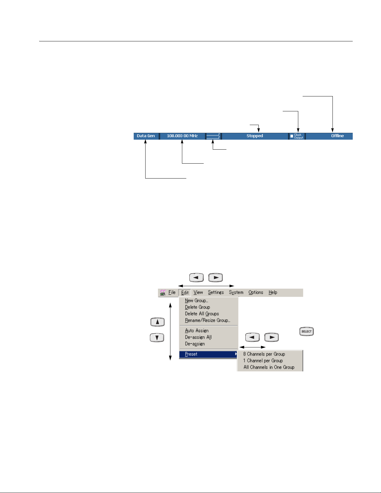
Operating Basics
Status Bar. The status bar provides useful information about the state of the data
timing generator operation or setup.
Online/Offline
Clock output
Run status
Run status animation
User clock frequency
Operating mode button
Figure 2-12: Status bar
Using the Menu System
Menu System
This section describes the basic operation of the data timing generator using the
front panel keys, buttons and knob.
Pushing the front panel MENU button displays the last menu you selected on the
menu bar.
Determine
the menu
Figure 2-13: Menu selection
DTG5078 & DTG5274 & DTG5334 Data Timing Generators Service Manual 2-35
Page 62

Operating Basics
A
Table 2-10: Menu selection
Key Description
Displays the last menu you selected on the menu bar.
Cancel the menu display when a menu is displayed.
Navigates through a pull-down menu list.
You can also use the knob instead of the arrow keys to navigate through a menu list.
Shows a submenu ( ).
Navigate s through the menu bar pressing on a menu item not having any submenu.
The menu is determined.
To cancel the menu display, press the ESC key twice.
When you press it only once, the menu bar is still active although the display disappears. In this
state, you can navigate through the menu bar by pressing the
keys.
Activates the menu bar. Then, you can make a menu selection using the
keys.
Pop-up Menu Items. In the individual data timing generator windows, selecting the
setup item and pushing the front panel SELECT button displays the pop-up menu
item(s) corresponding to the selected item.
Using a Window
The data timing generator windows contain various items of information. Input of
numeric values such as the output level and clock rate, selection of the trigger
source and other settings, creation of the pattern data, and other operations can be
performed.
、
、
2-36 DTG5078 & DTG5274 & DTG5334 Data Timing Generators Service Manual
Page 63

Operating Basics
3
2
1
4
Figure 2-14: Window operation: Time Base window
Table 2-11: Time Base Window operation
Key operation Description
1. To navigate through the Clock Source, Output Amplitude, and other similar items, use the
TA B key. You can navigate through these in the reverse direction by pressing the SHIFT and
TA B keys simultaneously. Displays the last menu you selected on the menu bar.
2. To select the parameter with radio buttons such as Clock Source or Trigger Source, use the
Up, Down, Left and/or Right arrow key.
3. Any numeric input box has a unit attribute according to the setting. The unit attribute s is for
the time, V for the voltage, Ω for the resistance, or nothing for the count or size. To enter a
numeric value, use either numeric keys or the knob. For details, see Numeric Input on page
2-38.
SPACE
4. To place the check sign into a check box such as Output On, use the SPACE key.
DTG5078 & DTG5274 & DTG5334 Data Timing Generators Service Manual 2-37
Page 64

Operating Basics
Numeric Input
Any numeric input box has a unit attribute according to the setting. The unit
attribute s is for the time, V for the voltage, Ω for the resistance, or nothing for the
count or size. The data timing generator recognizes the range of the acceptable
parameter values. If you enter a value outside the valid range, the maximum or
minimum value will be set automatically. To enter a numeric value, use either
numeric keys or the knob.
Using the Numeric Keys. Auxiliary unit keys such as k/m and M/µ are available.
For k (kilo-), m (milli-), M (mega-), and their related units, the one suitable for the
parameter is selected automatically.
Table 2-12: Example of Numeric Keys input
Key operation Description
Example 1: Amplitude
, , , and
, ,
Example 2: Term Z
, and
, and
If you press in this order, 0.5 V is entered.
If you press in this order, 0.5 V (500 mV) is
entered.
f you press in this order, 50 Ω is entered.
and
If you press in this order, 1 MΩ is entered.
Using the Knob. If a numeric value is accompanied with an underbar, you can use
the knob for editing it. The digit accompanied with an underbar can be edited.
To move the underbar to the target digit to be edited, use the Left and/or Right
arrow key under the knob. See Figure 2-5 on page 2-21 for the location of the key.
A numeric value accompanied
with underbar
2-38 DTG5078 & DTG5274 & DTG5334 Data Timing Generators Service Manual
Page 65

Operating Basics
Using the External Keyboard. Numeric keys above the alphabetical letter keys, not
those on the numeric keypad, are available on the external keyboard. The k (kilo-),
M (mega-), G (giga-), m (milli-), µ (micro-), n (nano-) and p (pico-) keys are
available for auxiliary units.
Text Input
To enter text from the front panel, use the ALPHA key and numeric keys.
Push the key to activate the text input mode. In this mode, you can enter
ALPHA
ALPHA
characters that are printed above each numeric key. The ALPHA key’s LED stays
lit if the text input mode is selected.
Table 2-13: Example of Numeric Keys input
Key operation Description
ALPHA
By pressing a numeric key repeatedly, the
Indicates DtG5000 is in the numeric input mode.
Pressing this key changes in the text input mode.
Indicates DtG5000 is in the text input mode.
Pressing this key changes in the numeric input
mode.
characters indicated above the key are displayed
Example: Pressing the 8 key displays a at the
caret. If you press the 8 key repeatedly, the
character changes to b, c, A, B, C and 8 in order.
another numeric key or
Right arrow key, the character currently displayed
is determined and the caret moves.
When you press another numeric key or the Left or
another numeric key or
Any key unrelated to text input or
By pressing the ENTER key or another numeric
key, the character is also determined.
If you press a key unrelated to text input or the
ESC key, or use the ENTER key to determine the
character, the mode automatically changes from
text input to numeric input.
DTG5078 & DTG5274 & DTG5334 Data Timing Generators Service Manual 2-39
Page 66

Operating Basics
File Operations
To save or load the setup file or import data that has been created on another device,
use the Windows standard file I/O dialog box. The data timing generator file
operations are the same as the general PC file operations. If the mouse is not used,
several restrictions are applied to the file operations.
Selecting a file. Do the followings steps to select a file without using a mouse.
Table 2-14: Selecting a file
Screen Key operations
1. Press the key
repeatedly to activate the file
view.
Activates
the file
view
2. Browsing a folder:
:select the
folder.
: open the folder
: move the folder
hierarchy up
2-40 DTG5078 & DTG5274 & DTG5334 Data Timing Generators Service Manual
Page 67

Table 2-14: Selecting a file (cont.)
Screen Key operations
3. Specify the file:
Operating Basics
:Select the file
: Open the file
Key Operations
Table 2-15 summarizes the data timing generator key operations.
Table 2-15: Key operations
Items Description
+
Displays the last menu you opened on the menu bar.
Moves the focus through items in the window. Pressing SHIFT and TAB
keys simultaneously reverses the moving direction.
Moves the cursor through items on the menu, moves the caret during
text input, or selects a radio button.
Selects multiple items (Data-Listing/Data-Waveform window), or shifts
the current line (SHIFT + Up/Down arrow key only; Timing/Level
window).
DTG5078 & DTG5274 & DTG5334 Data Timing Generators Service Manual 2-41
Page 68

Operating Basics
SPACE
DEL
Table 2-15: Key operations
Items Description
Changes a numeric value, moves the cursor through menu items, moves
the focus in a table or list, moves the cursor through the Data-Listing or
Data-Waveform window, toggles between multiple items for a parameter
in the Timing/Level window (NRZ/RZ/R1, On/Off, Normal/Invert,
Normal/AND/XOR, etc.), or selects an item from a combo box.
Select arrow keys
+
+
+
SPACE
+ F4
+
+
Digit
Located just below the knob. Moves the cursor through digits while using
the knob to enter a numeric value. Refer to page 2-21.
Turns on or off the check sign in a check box, or toggles between two
options for a parameter in the Timing or Level window (On/Off,
Normal/Invert, etc.).
Activates the menu bar.
Switches the active application.
Switches the application (selected with icon display).
Displays window control menu. You can move/resize/close the window.
Exits the application. (Available only from the external key board)
Cancels text input or a dialog box. Cancels display of a menu opened
with the SELECT key. To cancel a menu opened with the MENU key,
press ESC key twice.
Switches the active window in the application.
Moves the cursor between digits during numeric input.
+
+
+
Increments or decrements the value during numeric input.
Displays the Windows Start menu.
Forcibly exits the application. (Available only from the external key
board)
+
2-42 DTG5078 & DTG5274 & DTG5334 Data Timing Generators Service Manual
Page 69

Operating Basics
Keyboard and Mouse
As the standard accessories, a USB keyboard and USB mouse are shipped with the
data timing generator. Though it is possible to operate the instrument only with
front panel controls, attaching the mouse and external keyboard to the data timing
generator mainframe makes the operation more easily. Read the following topics
related to the mouse and external keyboard.
When you set up the Windows operating system or perform the system recovery,
the external keyboard and mouse are required.
You can connect or remove the USB devices while the data timing generator
powered on.
Mouse.
Using a mouse allows you to access the toolbar icons, each window buttons
and scroll bar which cannot be accessed from the data timing generator front
panel controls.
In the data editing windows such as Data-Listing or Data-Waveform, or in the
setup windows such as Timing or Level, you can access the area you cannot
access from the keyboard. By dragging, right clicking or left clicking the
mouse allows you to access those functions.
Keyboard.
The Delete and Back space (BS) functions are assigned to a single key. To use it as
BS, press Fn+Delete. If you want to use a key as labeled on the key front (such as
BS, F1, F2...), press it while holding down the Fn key.
The Z key operates as the Windows key.
You can assign the Delete key to the BS key using a SW3 DIP switch located
on the back. In this case, you can input Delete by pressing Fn+’. For details of
the DIP switches, refer to the underside of the keyboard.
After you power on the instrument for the first time, you have to set up
Windows. Connect the keyboard supplied with the instrument before turning
on the power.
NOTE. If you need to perform the system recovery, you must use a PS/2 keyboard
and PS/2 mouse.
DTG5078 & DTG5274 & DTG5334 Data Timing Generators Service Manual 2-43
Page 70

Operating Basics
2-44 DTG5078 & DTG5274 & DTG5334 Data Timing Generators Service Manual
Page 71

Theory of Operation
Page 72

Page 73

Theory of Operation
This section presents an overview of DTG5000 Series Data Timing Generator
hardware, the data structure, and operating modes to allow you to take full
advantage the capabilities of the data timing generator.
Interconnect Diagrams
Figure 3-1, 3-2, and 3-3 show the data timing generator circuitry. This section
describes the hardware blocks that provide the background knowledge necessary to
use the instrument effectively.
The DTG5000 Series consists of four major electrical sections: Mainframe section,
Main board (A50/A51/A54), Output board (A60/A61/A62/A63), and Output
Module (DTGM10/M20/M21/M30/M31/M32).
Mainframe Section
The mainframe section consists of the following modules and components:
Compact PCI CPU Module
The Compact PCI CPU Module contains a Celeron CPU, DRAM, and HDD. This
module has various connectors on rear panel, such as VGA, LAN (100 Base-T),
Key Board (PS2), Mouse (PS2), USB1.1 (2 each), and COM.
The Compact PCI CPU Module receives commands from the Front Key Board,
GPIB interface and Ethernet interface, controls all hardware in DTG5000 Series by
DTG5000 series product software. All control signals are transmitted through the
PCI I/F Board.
A30 Compact PCI Backplane board
The A30 Compact PCI Backplane board consists of a few decoupling capacitors
and LVDS panel control for EMI. The back plane has two Compact PCI slots and
three local bus slot. This board receives power from the Power Supply module
through the A10 Connector & PCI I/F board and sends power to the CPU board.
This board also has the local bus for operating various hardware in the DTG5000
Series.
DTG5078 & DTG5274 & DTG5334 Data Timing Generators Service Manual 3-1
Page 74

Theory of Operation
A10 Connector & PCI Interface board
The A10 Connector & PCI Interface board supplies power to all modules and
converts a PCI bus to a local bus. This board also handles Power On control, Fan
control, and LVDS Panel Control.
Compact PCI GPIB Module
The Compact PCI GPIB Module is a Compact PCI GPIB card (PXI-GPIB) made
by National Instruments. Refer to the National Instruments user manual for details.
This module is controlled by the Microsoft Windows 2000 Operating System.
CD-ROM Module
The CD-ROM Module is placed on the A32 CD-ROM Extender board with the
dedicated flexible circuit board. This CD-ROM Module is controlled by the
Microsoft Windows 2000 Operating System.
LCD Display & Back light
The LCD Monitor is a TFT-type LCD module. This module receives the video
signal from the CPU Board through the A10 Connector & PCI Interface board.
A20 Front Key & DC Output Board
The A20 Front Key & DC Output board contains a scan rubber button matrix,
LEDs, a rotary encoder and DC Output circuitry. This keyboard interface is
compatible with the AWG400/500/600/700 series arbitrary waveform generator.
Power Supply Module
Power Supply Module provides +5 V, +3.3 V, -4.5 V, -2 V, +12 V, and -8 V. This
module features the voltage switching regulation and the remote switching
mechanism for the ON/STBY switch on the front panel. The Power Supply module
sends various regulated voltages to all boards in the mainframe through the A10
Connector and PCI Interface board. The remote switching signal that is generated
on the front panel is sent to the CPU Module through the A10 Connector & PCI
Interface board. The CPU Module controls the power supply by using the remote
control with the Power Supply Module. Software shutdown is also available.
3-2 DTG5078 & DTG5274 & DTG5334 Data Timing Generators Service Manual
Page 75

Theory of Operation
Main Board Section
(A50/A51/A54)
Output Board Section
(A60/A61/A62/A63)
Output Module Section
(DTGM10/M20/M21/
M30/M31/M32)
The Main board consists of CPU Interface, Pattern Memory, Sequencer, PLL,
Trigger Control, Clock Out (DTG5078: A54, DTG5274: A50, DTG5334: A51).
The Output board consists of Delay Line and CPU interface (DTG5078: A62&
A63), DTG5274: A60, DTG5334: A61).
The Output Module consists of Pin-Driver IC, relay, FPGA for signal decoding.
Six kinds of Output Module are prepared at this time. The main difference between
these Output Modules is that a different pin driver IC is adopted. These six Outputs
Modules are called DTGM10, DTGM20, DTGM21, DTGM30, DTGM31 and
DTGM32.
DTG5078 & DTG5274 & DTG5334 Data Timing Generators Service Manual 3-3
Page 76

Theory of Operation
L
/
S
S
p
C
Interface
L
/
S
S
p
C
Interface
DTGM10/20/21/30/31/32
Pin
CPU
Driver
Interface
DATA OUT
SKEW CAL IN
TRIGGER IN
EVENT IN
SYNC OUT
Lead
Relay
DTGM10/2X/3X
DTGM10/2X/3X
DTGM10/2X/3X
DTGM10/2X/3X
DTGM10/2X/3X
DTGM10/2X/3X
DTGM10/2X/3X
DTGM10/2X/3X
Buffer
Power Supply
Power Supply
PU
Delay
Line
evel
lew
etu
A63 Output
PU
Delay
Line
evel
lew
etu
A62 Output
CPU Interface
Pattern Memory
Sequencer
Clock Generator
Trigger Control
Clock Out
A54 Main
EXTERNAL IN
OUT
OUT
10 MHz REF IN
10 MHz REF OUT
PHASE LOCK IN
CLK IN
CLK IN
CLK OUT1
CLK OUT1
CLK OUT2
CLK OUT2
CLK OUT3
CLK OUT3
JUMP IN
JUMP OUT1
JUMP OUT2
JUMP OUT3
CLOCK
PHASE
LOCK
MASTER/SLAVE CONNECTION
Local Bus
Fan Left Side
(6 ea)
Fan Right Side
(2 ea)
Parallel
LCD Display
A22 Power Switch
FP Processor
Key/LED USB
CPU Interface
Back Light
Local Bus
DC Out
A20 Front Key & DC Output
Rotary Encoder
FDD
Safty GND
Power Supply
AC
Module
Figure 3-1: DTG5078 interconnection diagram
Power Supply
Fan
Control
LVD S
Panel
Control
+12V
Compact
PCI
Interface
Power
On/Off
Control
A10 Connector
&
PCI Interface
+12V, +5V, +3.3V
-2V, -4.5V, -8V
Mainframe Section
Serial
Compact
PCI Bus
LVDSPanel
Control
A30 Compact
PCI Backplane
Parallel
Compact
PCI Bus
CPU Celeron
566MHz
DRAM 128M
HDD
Compact PCI
CPU Module
USB (2 ea)
Compact PCI GPIB Card
CD-ROM
Module
A32 CD-ROM Extender
VGA
LAN
Keyboard
Mouse
COM
3-4 DTG5078 & DTG5274 & DTG5334 Data Timing Generators Service Manual
Page 77

Theory of Operation
L
/
S
S
CPU
I
DTGM10/20/21/30/31/32
Pin
CPU
Driver
Interface
DATA OUT
SKEW CAL IN
TRIGGER IN
EVENT IN
SYNC OUT
Lead
Relay
DTGM10/2X/3X
DTGM10/2X/3X
DTGM10/2X/3X
DTGM10/2X/3X
Buffer
A60 Output
Power Supply
nterface
Delay
Line
evel
lew
etup
CPU Interface
Pattern Memory
Sequencer
Clock Generator
Trigger Control
Clock Out
A50 Main
EXTERNAL IN
OUT
OUT
10 MHz REF IN
10 MHz REF OUT
PHASE LOCK IN
CLK IN
CLK IN
CLK OUT1
CLK OUT1
CLK OUT2
CLK OUT2
JUMP IN
JUMP OUT1
JUMP OUT2
CLOCK
PHASE
LOCK
MASTER/SLAVE CONNECTION
Local Bus
Fan Left Side
(6 ea)
Fan Right Side
(2 ea)
Parallel
LCD Display
A22 Power Switch
FP processor
Key/LED USB
CPU Interface
Back Light
Local Bus
DC Out
A20 Front Key & DC Output
Rotary Encoder
FDD
Safty GND
Power Supply
AC
Module
Figure 3-2: DTG5274 interconnection diagram
Power Supply
Fan
Control
LVD S
Panel
Control
+12V
Compact
PCI
Interface
Power
On/Off
Control
A10 Connector
&
PCI Interface
+12V, +5V, +3.3V
-2V, -4.5V, -8V
Mainframe Section
Serial
Compact
PCI Bus
LVDSPanel
Control
A30 Compact
PCI Backplane
Parallel
Compact
PCI Bus
CPU Celeron
566MHz
DRAM 128M
HDD
Compact PCI
CPU Module
Compact PCI GPIB Card
CD-ROM
Module
A32 CD-ROM Extender
VGA
LAN
Keyboard
Mouse
USB (2 ea)
COM
DTG5078 & DTG5274 & DTG5334 Data Timing Generators Service Manual 3-5
Page 78

Theory of Operation
L
/
S
S
CPU
I
DTGM10/20/21/30/31/32
Pin
CPU
Driver
Interface
Lead
Relay
Buffer
CPU Interface
DATA OUT
SKEW CAL IN
EXTERNAL IN
OUT
CLOCK
OUT
TRIGGER IN
EVENT IN
SYNC OUT
DTGM10/2X/3X
DTGM10/2X/3X
DTGM10/2X/3X
DTGM10/2X/3X
Fan Left Side
(6 ea)
Fan Right Side
(2 ea)
LCD Display
A22 Power Switch
FP Processor
Key/LED USB
CPU Interface
DC Out
A20 Front Key & DC Output
A61 Output
Power Supply
Back Light
nterface
Delay
Line
evel
lew
etup
Local Bus
Local Bus
Parallel
Fan
Control
LVD S
Panel
Control
+12V
Compact
PCI
Interface
Power
On/Off
Control
Pattern Memory
Sequencer
Clock Generator
Trigger Control
Clock Out
A51 Main
Power Supply
Serial
Compact
PCI Bus
LVDSPanel
Control
Parallel
Compact
PCI Bus
10 MHz REF IN
10 MHz REF OUT
PHASE LOCK IN
CLK IN
CLK IN
CLK OUT1
CLK OUT1
CLK OUT2
CLK OUT2
JUMP IN
JUMP OUT1
JUMP OUT2
CPU Celeron
566MHz
DRAM 256M
HDD
Compact PCI
CPU Module
Compact PCI GPIB Card
VGA
LAN
Keyboard
Mouse
USB (2 ea)
COM
PHASE
LOCK
MASTER/SLAVE CONNECTION
Rotary Encoder
Safty GND
AC
FDD
Power Supply
Module
A10 Connector
&
PCI Interface
+12V, +5V, +3.3V
-2V, -4.5V, -8V
A30 Compact
PCI Backplane
CD-ROM
Module
A32 CD-ROM Extender
Mainframe Section
Figure 3-3: DTG5334 interconnection diagram
3-6 DTG5078 & DTG5274 & DTG5334 Data Timing Generators Service Manual
Page 79

Block Diagrams
Theory of Operation
Figure 3-4, 3-5 and 3-6 show the main hardware blocks that make up the DTG5000
series. The DTG5000 series consists of three parts: Clock Generator, Pattern
Generator, and Timing Control & Output.
Clock Generator
Pattern Generator
The Clock Generator consists of 10 MHz TCXO, External 10 MHz Reference,
DDS (Direct Digital Synthesis), PLL (Phase Locked Loop), Divider, ASIC
including Divider and Trigger Control, and Clock Out. DDS generates a clock from
1 MHz to 2 MHz as a reference signal of an internal 10 MHz TCXO or an external
10 MHz Reference signal selected by SW1. The PLL generates a clock from 500
MHz to 1 GHz in the DTG5078 and from 2 GHz to 4 GHz in the DTG5274/
DTG5334. Either the DDS output or an external divided Phase Lock In is the
reference signal for PLL. SW2 selects one of these signals as a reference source.
SW3 selects either the PLL output or external CLOCK IN as an internal clock.
SW4 should be connected to the CLK IN for Master-Slave in the case of
Master-Slave Operation. The internal clock generated at this block is sent to
several circuits in the Pattern generator block. The External Clock out can be
controlled by the amplitude and offset because this has a high speed pin driver.
The Pattern Generator consists of Sequence RAM, Sequencer, Pattern RAM, Shift
Register, and Latch. Sequence RAM is the memory for the Sequence Program that
a user defines. Sequencer outputs arbitrary pattern data according to the Sequence
Program written to the Sequence RAM. Sequencer also controls an event jump
sequence when the event occurs. Shift Register accelerates Pattern Data supplied
from Pattern RAM 15 times or 16 times. This Pattern Data is sent to Timing
Control & Output after the data is latched. In the case of the DTG5274/DTG5334,
this latched data is accelerated again four times at 4:1 MUX. This Latch and 4:1
MUX are included in the ASIC. Jump In and Jump Out are used for Master-Slave
operation. Sync Out is useful as an external trigger signal for the oscilloscope.
Timing Control & Output
DTG5078 & DTG5274 & DTG5334 Data Timing Generators Service Manual 3-7
Timing Control & Output consists of Delay Line & Pulse Width Control, Jitter
Generation Control, Jitter Pattern RAM, Fine Delay Line, Skew Time Detector,
Pin Driver and Relay. Delay Line & Pulse Width Control change the delay time or
pulse width of the data pattern. This block also generates the intentional jitter
according to the pattern written in Jitter Pattern RAM by changing the delay time.
Jitter Generation Control drives this intentional jitter. Fine Delay Line produces the
delay time resolution of 1 ps in DTG5078 and 0.2 ps in DTG5274/DTG5334.
DTGM10/M20/M21/M30/M31/M32 has the Pin Driver IC and the Relay for
opening the outputs.
Page 80

Theory of Operation
Pin Drive
EXTERNAL 10MHz
REF IN
10MHz
TCXO
PHASE LOCK IN
EXTERNAL
CLOCK IN
CLK IN
for Master/Slave
TRIGGER IN
Clock Generator (A54)
SW1
SW3
Pattern RAM Shift Register
DDS
Divider
SW4
ASIC
Divider
Trigger
Control
Latch
SW2
PLL
10MHz REF OUT
EXTERNAL CLOCK OUT
(Complementary)
CLK OUT
for Master/Slave
(3Ch Complementary)
SYNC OUT
Sequence
RAM
EVENT IN
JUMP IN
for Master/Slave
Pattern Generator (A54)
Delay Line
&
Pulse Width Control
Jitter Generation
Control
Timing Control & Output (A62/A63)
Figure 3-4: DTG5078 block diagram
Sequencer
Fine Delay Line
Jitter Pattern
RAM
SKEW CAL IN
A62 Only
DTGM10/M20/M21/M30/M31/M32
r Relay
A74/A72/A82/A70/A80/A81
Skew Time
Detector
JUMP OUT
for Master/Slave (3Ch)
DATA OUT
3-8 DTG5078 & DTG5274 & DTG5334 Data Timing Generators Service Manual
Page 81

Theory of Operation
Pin Drive
EXTERNAL 10MHz
REF IN
10MHz
TCXO
PHASE LOCK IN
EXTERNAL
CLOCK IN
CLK IN
for Master/Slave
TRIGGER IN
Clock Generator (A50)
SW1
SW3
Pattern RAM Shift Register
DDS
Divider
SW4
Divider
Trigger
Control
ASIC
Latch
SW2
4:1
MUX
PLL
10MHz REF OUT
EXTERNAL CLOCK OUT
(Complementary)
CLK OUT
for Master/Slave
(2Ch Complementary)
SYNC OUT
Sequence
RAM
EVENT IN
JUMP IN
for Master/Slave
Pattern Generator (A60)
Delay Line
&
Pulse Width Control
Jitter Generation
Control
SKEW CAL IN
Timing Control & Output (A60)
Figure 3-5: DTG5274 block diagram
Sequencer
Fine Delay Line
Jitter Pattern
RAM
Skew Time
Detector
DTGM10/M20/M21/M30/M31/M32
r Relay
A74/A72/A82/A70/A80/A81
JUMP OUT
for Master/Slave (2Ch)
DATA OUT
DTG5078 & DTG5274 & DTG5334 Data Timing Generators Service Manual 3-9
Page 82

Theory of Operation
Pin Drive
EXTERNAL 10MHz
REF IN
10MHz
TCXO
PHASE LOCK IN
EXTERNAL
CLOCK IN
CLK IN
for Master/Slave
TRIGGER IN
Clock Generator (A51)
SW1
SW3
Pattern RAM Shift Register
DDS
Divider
SW4
Divider
Trigger
Control
ASIC
Latch
SW2
MUX
10MHz REF OUT
PLL
EXTERNAL CLOCK OUT
(Complementary)
CLK OUT
for Master/Slave
(2Ch Complementary)
4:1
SYNC OUT
Sequence
RAM
EVENT IN
JUMP IN
for Master/Slave
Pattern Generator (A61)
Delay Line
&
Pulse Width Control
Jitter Generation
Control
SKEW CAL IN
Timing Control & Output (A61)
Figure 3-6: DTG5334 block diagram
Sequencer
Fine Delay Line
Jitter Pattern
RAM
Skew Time
Detector
DTGM10/M20/M21/M30/M31/M32
r Relay
A74/A72/A82/A70/A80/A81
JUMP OUT
for Master/Slave (2Ch)
DATA OUT
3-10 DTG5078 & DTG5274 & DTG5334 Data Timing Generators Service Manual
Page 83

Performance Verification
Page 84

Page 85

Performance Verification
The performance verification procedures for this instrument are now available on
the DTG5078 & DTG5274 & DTG5334 Performance Verification &
Specifications Technical Reference (Tektronix part number 071-1611-xx). A pdf of
this technical reference is provided on the DTG5000 Series Product Documents
CD-ROM (Tektronix part number 063-3833-xx) that shipped with your product.
DTG5078 & DTG5274 & DTG5334 Data Timing Generators Service Manual 4-1
Page 86

Performance Verification
4-2 DTG5078 & DTG5274 & DTG5334 Data Timing Generators Service Manual
Page 87

Adjustment Procedures
Page 88

Page 89

Adjustment Procedures
There are no adjustments. All boards are adjusted when they are shipped from the
factory.
DTG5078 & DTG5274 & DTG5334 Data Timing Generators Service Manual 5-1
Page 90

Adjustment Procedures
5-2 DTG5078 & DTG5274 & DTG5334 Data Timing Generators Service Manual
Page 91

Maintenance
Page 92

Page 93

Maintenance
This section contains the information needed to do periodic and corrective
maintenance on the DTG5000 Series
The following subsections are included:
Related Maintenance Procedures — Provides information about various
sections that have related maintenance information.
Preparation — Introduction plus general information on preventing damage to
internal modules when doing maintenance.
Inspection and Cleaning — Information and procedures for inspecting the data
timing generator and cleaning its external and internal modules.
Removal and Installation Procedures — Procedures for the removal of
defective modules and replacement of new or repaired modules.
Troubleshooting — Information for isolating failed modules. Included are
instructions for operating the internal diagnostic routines of the data timing
generator and troubleshooting trees. Most of the trees make use of these
internal diagnostic routines to speed fault isolation to a module.
data timing generator.
System recovery — Information for software installation. When operating
system does not start up, you may have to reinstall the operating system for
recovery. This section includes information for reinstalling the operating
system, setting up the operating system and reinstalling the DTG5000
software.
Service Password — Information for registration of serial number.
Related Maintenance Procedures
The following sections contain information and procedures related to maintenance.
The Operating Information section is useful when you troubleshoot. It also
details the service strategy and lists options for obtaining maintenance service
and for replacing failed modules.
The Theory of Operation section contains a circuit description at the module,
or block, level.
The Performance Verification section in the DTG5000 Series Technical
Reference for Performance Verification & Specifications contains procedures
that may be useful in isolating problems to modules by testing product
performance.
DTG5078 & DTG5274 & DTG5334 Data Timing Generators Service Manual 6-1
Page 94

Maintenance
Preparation
The Diagrams section contains a block diagram using individual modules as
blocks and an interconnection diagram showing connections between the
modules.
The Replaceable Mechanical Parts section, lists all field replaceable modules
by part number.
Before servicing this product, read the Safety Summary and Introduction at the
front of the manual and the ESD information below.
CAUTION. Static discharge can damage any semiconductor component in this
generator.
Preventing ESD
NOTE. If you are removing a module for service, begin by doing the Access
Procedure procedure on page 6-13. By following the instructions in that procedure,
you remove the module to be serviced while removing the minimum number of
additional modules.
When performing any service that requires internal access to the data timing
generator, adhere to the following precautions to avoid damaging internal modules
and their components due to electrostatic discharge (ESD).
1. Minimize handling of static-sensitive modules.
2. Transport and store static-sensitive modules in their static protected containers
or on a metal rail. Label any package that contains static-sensitive modules.
3. Discharge the static voltage from your body by wearing a grounded antistatic
wrist strap while handling these modules. Service static-sensitive modules
only at a static-free work station.
4. Do not allow anything capable of generating or holding a static charge on the
work station surface.
5. Handle circuit boards by the edges when possible.
6. Do not slide the modules over any surface.
7. Avoid handling modules in areas that have a floor or work-surface covering
that is capable of generating a static charge.
6-2 DTG5078 & DTG5274 & DTG5334 Data Timing Generators Service Manual
Page 95

Inspection and Cleaning
Maintenance
Inspection and Cleaning describes how to inspect for dirt and damage. It also
describes how to clean the exterior and interior of the DTG5000 Series data timing
generators. Inspection and cleaning are done as preventive maintenance.
Preventive maintenance, when done regularly, may prevent data timing generator
malfunctions and enhance reliability.
Preventive maintenance consists of visually inspecting and cleaning the data
timing generator and using general care when operating it.
How often to do maintenance depends on the severity of the environment in which
the data timing generator is used. A proper time to perform preventive maintenance
is just before generator adjustment.
General Care
Inspection and Cleaning
procedures
The cabinet helps keep dust out of the data timing generator and should normally
be in place when operating the generator. The front cover protects the front-panel
and display from dust and damage. Install the front cover when storing or
transporting the data timing generator.
Inspect and clean the data timing generator as often as operating conditions require.
The collection of dirt on components inside can cause them to overheat and
breakdown. (Dirt acts as an insulating blanket, preventing efficient heat
dissipation.) Dirt also provides an electrical conduction path
generator failure, especially under high-humidity conditions.
CAUTION. Avoid the use of chemical cleaning agents which might damage the
plastics used in this DTG5000 Series data timing generator. Use only deionized
water when cleaning the front-panel buttons. Use an ethyl alcohol solution as a
cleaner and rinse with deionized water. Before using any other type of cleaner,
consult your Tektronix Service Center or representative.
that could cause an
DTG5078 & DTG5274 & DTG5334 Data Timing Generators Service Manual 6-3
Page 96

Maintenance
Inspection — Exterior. Inspect the outside of the generator for damage, wear, and
missing parts, using Table 6-1 as a guide. Data timing generators that appear to
have been dropped or otherwise abused should be checked thoroughly to verify
correct operation and performance. Immediately repair defects that could cause
personal injury or cause further data timing generator damage.
Table 6-1: External inspection check list
Item Inspect for Repair action
Cabinet, front-panel, and cover Cracks, scratches,
deformations, damaged
hardware or gaskets.
Front-panel knobs Missing, damaged, or loose
knobs.
Connectors Broken shells, cracked
insulation, and deformed
contacts. Dirt in connectors.
Carrying handle, bail, cabinet
feet.
Accessories Missing items or parts of items,
Correct operation. Repair or replace defective
bent pins, broken or frayed
cables, and damaged
connectors.
Repair or replace defective
module.
Repair or replace missing or
defective knobs.
Repair or replace defective
modules. Clear or wash out
dirt.
module.
Repair or replace damaged or
missing items, frayed cables,
and defective modules.
Cleaning Procedure — Exterior. Do the following steps to clean the data timing
generator exterior:
1. Remove loose dust on the outside of the data timing generator with a lint free
cloth.
2. Remove remaining dirt with a lint free cloth dampened in a general purpose
detergent-and-water solution. Do not use abrasive cleaners.
3. Clean the light filter protecting the monitor screen with a lint-free cloth
dampened with either ethyl alcohol or, preferably, a gentle, general purpose
detergent-and-water solution.
CAUTION. To prevent getting moisture inside the generator during external
cleaning, use only enough liquid to dampen the cloth or applicator.
6-4 DTG5078 & DTG5274 & DTG5334 Data Timing Generators Service Manual
Page 97

Maintenance
Flat Panel Display Cleaning. The display is a soft plastic display and must be
treated with care during cleaning.
CAUTION. Imported cleaning agents or methods can damage the flat panel display.
Avoid using abrasive cleaners or commercial cleaners to clean the display surface.
Avoid spraying liquids on the display surface.
Avoid scrubbing the display with excessive force.
Clean the flat panel display surface by gently rubbing the display with a clean-room
wipe (such as Wypall Medium Duty Wipes, #05701, available from
Kimberly-Clark Corporation).
If the display is very dirty, moisten the wipe distilled water or a 75% isopropyl
alcohol solution and gently rub the display surface. Avoid using excess force or
you may damage the plastic display surface.
CAUTION. To prevent getting moisture inside the data timing generator during
external cleaning, use only enough liquid to dampen the cloth or applicator.
Inspection — Interior. To access the inside of the data timing generator for
inspection and cleaning, refer to the Removal and Installation Procedures in this
section.
Inspect the internal portions of the data timing generator for damage and wear,
using Table 6-2 as a guide. Defects found should be repaired immediately.
CAUTION. To prevent damage from electrical arcing, ensure that circuit boards
and components are dry before applying power to the data timing generator.
Table 6-2: Internal inspection check list
Item Inspect for Repair action
Circuit boards Loose, broken, or corroded
solder connections. Burned
circuit boards. Burned, broken,
or cracked circuit-run plating.
Resistors Burned, cracked, broken,
blistered condition.
Solder connections Cold solder or rosin joints. Resolder joint and clean with
Capacitors Damaged or leaking cases.
Corroded solder on leads or
terminals.
Remove failed module and
replace with a new module.
Exchange of a new circuit
board unit.
ethyl alcohol.
Exchange of a new circuit
board unit.
DTG5078 & DTG5274 & DTG5334 Data Timing Generators Service Manual 6-5
Page 98

Maintenance
Table 6-2: Internal inspection check list (cont.)
Item Inspect for Repair action
Semiconductors Loosely inserted in sockets.
Distorted pins.
Wiring and cables Loose plugs or connectors.
Burned, broken, or frayed
wiring.
Chassis Dents, deformations, and
damaged hardware.
Firmly seat loose
semiconductors. Remove
devices that have distorted
pins. Carefully straighten pins
(as required to fit the socket),
using long-nose pliers, and
reinsert firmly. Ensure that the
straightening action does not
crack pins, causing them to
break off.
Firmly seat connectors. Repair
or replace modules with
defective wires or cables.
Straighten, repair, or replace
defective hardware.
Cleaning Procedure — Interior. Do the following steps to clean the generator
interior:
1. Blow off dust with dry, low-pressure, deionized air (approximately 9 psi).
2. Remove any remaining dust with a lint-free cloth dampened in isopropyl
alcohol (75% solution) and rinse with warm deionized water. (A cotton-tipped
applicator is useful for cleaning in narrow spaces and on circuit boards.)
NOTE. If steps 1 and 2 do not remove all the dust or dirt, please contact your local
Tektronix service or Beaverton service center.
Lubrication. There is no periodic lubrication required for the data timing generator.
6-6 DTG5078 & DTG5274 & DTG5334 Data Timing Generators Service Manual
Page 99

Removal and Installation Procedures
This subsection contains procedures for removal and installation of mechanical and
electrical modules. Any electrical or mechanical module, assembly, or part listed
in the Replaceable Mechanical Parts section of this manual is a module.
Preparation for Use
WARNING. Before doing this or any other procedure in this manual, read the
Safety Summaries at the beginning of this manual. Also, to prevent possible injury
to service personnel or damage to components, read Operating
Information:Installation (on page 2-7) and Preventing ESD (on page 6-2).
This subsection contains the following items:
This preparatory information that you need to properly do the procedures that
follow.
A list of tools that are required to remove and disassemble all modules.
Three module-locator diagrams for finding the External Modules (see
Figure 6-2), Front-Panel and Display Modules (see Figure 6-3), and
Inner-Chassis Modules (see Figure 6-4 and Figure 6-5).
Procedures for removal and installation of the electrical and mechanical
modules.
A disassembly procedure for removal of all the major modules from the data
timing generator at one time and for reassembly of those modules. A complete
disassembly is normally only done when completely cleaning the data timing
generator. (Instructions for doing the actual cleaning are found under
Inspection and Cleaning at the beginning of this section.)
WARNING. To prevent serious injury or death, disconnect the power cord from the
line voltage source before doing any procedure in this subsection.
DTG5078 & DTG5274 & DTG5334 Data Timing Generators Service Manual 6-7
Page 100

Removal and Installation Procedures
Summary of Procedures
The following procedures are described in the order in which they appear in this
section.
The Access Procedure on page 6-13 directs you to the procedure(s) (if any) that
are required to access the module to be serviced, and then it directs you to the
procedure to remove that module.
Procedures for External Modules on page 6-14 are procedures for removing
modules that do not require internal access to the data timing generator.
Procedures for Internal Modules (Lower) on page 6-30 are procedures for
removing modules which require access to the internal lower part of the data
timing generator chassis.
Procedures for Internal Modules (Upper) on page 6-40 are procedures for
removing modules which require access to the internal upper part of the data
timing generator chassis.
Equipment Required. Most modules in the data timing generator can be removed
using a screwdriver with a #2 Phillips tip (see Table 6-3). Use this tool whenever a
procedure step instructs you to remove or install a screw unless a different size
screwdriver is specified in that step. All equipment required to remove and install
a module are listed in the first step of each procedure.
Table 6-3: Tools required for module removal
Item no. Name Description
1 Screwdriver handle Accepts Phillips-driver bits
2 #1 Phillips tip Phillips-driver bit for #1 screw size
3 #2 Phillips tip Phillips-driver bit for #2 screw size
4 Flat-blade screwdriver Screwdriver for removing slotted screws
5 Needle-Nose Pliers Standard tool
1
6 Nutdriver,
7 Nutdriver, 5 mm Standard tool
8 Nutdriver, 7 mm Standard tool
9 Nutdriver, 10 mm Standard tool
10 Retaining Ring Pliers Standard tool
11 Angle-Tip Tweezers Standard tool
12 Pliers Standard tool
13 Cable remover U.FL cable remover by HIROSE
14 Soldering Iron Standard tool
15 Solder Wick Standard tool
16 Adhesive TRA-CON: Tra-Bond #BA-2114
@2 inch Standard tool
6-8 DTG5078 & DTG5274 & DTG5334 Data Timing Generators Service Manual
 Loading...