

Page 1
Application Note
HDMI Compliance and Sink Characterization Using the
DTG5000 Series Data Timing Generator
Introduction
The High Definition Multimedia Interface (HDMI) is
an emerging consumer electronics standard that is
fast gaining acceptance by manufacturers of digital
tainment pr
enter
one-cable inter
and audio content between receiver/playback
devices and display devices.
ypical r
T
boxes, DVD players, satellite r
Definition tuners as well as personal computers.
Display devices connected via HDMI include LCD
eceiver/playback devices include cable
oducts. HDMI offers an efficient
face for High Definition (HD) video
eceivers, and High
displays, plasma displays, and pr
Thanks to the simplicity of setup and the resulting
quality of the presentation, consumers are accepting
HDMI as a “must-have” item for the full HD experience.
HDMI uses the existing Digital Video Interface (DVI)
architecture and adds capability for High Definition
Audio and High-Bandwidth Digital Content Protection
(HDCP). The latter technology enables tr
protection of high-quality digital movie content.
HDCP is r
entertainment industry, which is advocating its use in
all HD consumer products.
eceiving an enthusiastic response from the
ojection units.
ue copy
Page 2
DMI Compliance & Sink Characterization Using DTG5000 Series Data Timing Generator
H
Application Note
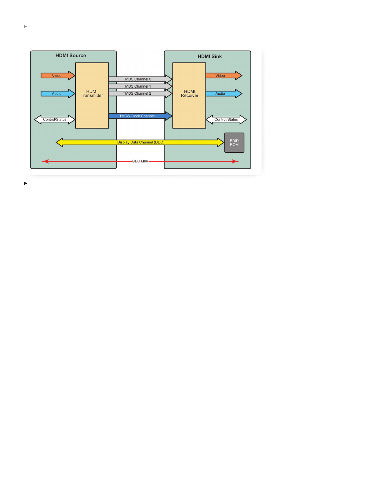
Figure 1.
HDMI pixel data flow and organization from Source to Sink.
HDMI supports standard, enhanced, or HD video as
well as standard or multi-channel surround audio. The
interface offers uncompressed digital video and a
bandwidth of up to 5 gigabytes per second through
one small connector instead of several cables and
connectors as in the past. In addition, HDMI enables
communication between the video source and the
digital television (DTV). HDMI development is overseen by HDMI Founders including Sony, Hitachi,
Panasonic (Matsushita Electric Industrial), Silicon
Image, Philips, Thomson (RCA) and T
oshiba.
The HDMI Founders have stipulated that all HDMI
products must pass a battery of required compliance
tests to qualify to use the HDMI logo. This compliance
testing will ensure true interoperability and accordingly,
customer satisfaction. Today, these tests can only be
performed at an HDMI Authorized Testing Centers
TC). Pr
(A
e-compliance testing during the design and
manufacturing stages greatly increases the likelihood
of successfully passing the final compliance tests at
the ATC. Pre-compliance testing can save valuable
time and resources.
This technical brief discusses the equipment required
for pre-compliance and compliance testing to the HDMI
physical layer Compliance Test Specifications (CTS).
HDMI Technical Characteristics
HDMI uses a high-speed serial interface that is based
on transition-minimized differential signaling (TMDS)
to send data to the r
eceiver
. TMDS signals transition
between “on” and “off” states using an algorithm that
minimizes the number of transitions to avoid excessive
levels of electr
omagnetic inter
ference (EMI) on the
cable. The differential signal amplitude is +3.3 volts,
terminated in 50 Ω with 500 mV nominal amplitude
transitions (from +2.8 V to +3.3 V).
2
2
2
www.tektronix.com/signal_sources
Page 3
DMI Compliance & Sink Characterization Using DTG5000 Series Data Timing Generator
H
Application Note
Standard Resolution Data Rate Frequency
VGA 640 x 480 252 Mb/s 25.2 MHz
SVGA 800 x 600 400 Mb/s 40 MHz
XGA 1024 x 768 650 Mb/s 65 MHz
SXGA 1280 x 1024 1080 Mb/s 108 MHz
UXGA 1600 x 1200 1620 Mb/s 162 MHz
640 x 480p 640 x 480 252 Mb/s 25.2 MHz
720 x 480p 720 x 480 270.27 Mb/s 27.027 MHz
576p 768 x 576 270 Mb/s 27 MHz
720p 1280 x 720 742.5 Mb/s 74.25 MHz
1
080i 1920 x 1080 742.5 Mb/s 74.25 MHz
Table 1.
Display Clock
Standards and respective data rates.
The basic TMDS transmission line is made up of three
data channels and a clock channel. Data consists of
8-bit pixels (256 discrete levels) in each of three
channels (R/G/B). These are encoded into ten-bits
words using 8B/10B encoding to minimize transitions
and to remove the DC component. The signals have
rise times on the order of 100 picoseconds. A pair of
TMDS lines is used when higher data rates are needed.
Figure 1 shows the flow of pixel data from the
graphics controller or Source device to the digital
Sink receiver.
TMDS data rates range fr
om 22.5 megapixels per
second (Mpps) to 165 Mpps, equivalent to or up to
1.65 G bits per second at the maximum clock rate
of 165 MHz. The data rate depends on the display
resolution. The relationships of display resolution, bit
rate and clock frequency are shown in the Table 1.
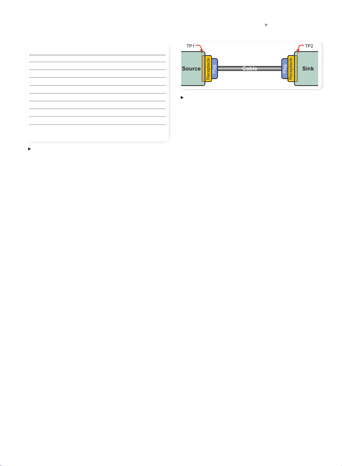
Figure 2.
Test points for HDMI measurements.
Compliance Testing Tools and Solutions DTG5000 Series
The goal of compliance testing is to ensur
e interoperability among the many hundreds of different HDMI
devices from as many manufacturers. By conforming
to published HDMI specifications, a device manufactur
can pave the way for a new product's acceptance in
the marketplace.
esting should also ensure that the designs are robust
T
enough to withstand the harsh treatment they can
expect to receive in the real world. As new displays
become more rugged, the devices that use them will
find their way into less sheltered environments than in
the past. Therefore, new devices should be tested to
comply with standards under a variety of operating
conditions, not just “nominal” or best-case conditions.
est parameters should r
T
each out beyond the basic
limits defined in the specifications.
Figure 2 illustrates the major elements of the HDMI
transmission system: Source, Cable and Sink. The
ce signals ar
Sour
e tested at TP1 while the Sink
devices are tested at TP2. For testing cables, meas-
ements must be performed at both TP1 and TP2.
ur
er
www.tektronix.com/signal_sources
3
Page 4
DMI Compliance & Sink Characterization Using DTG5000 Series Data Timing Generator
H
Application Note
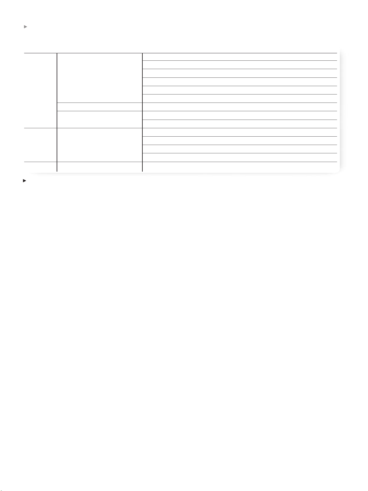
Electrical Signals Test CTS Test ID Test Point
Source Clock and/or Data Data Eye Diagram 7-10 TP1
Clock Jitter 7-9 TP1
Clock Duty Cycle 7-8 TP1
Overshoot/Undershoot 7-5 TP1
Rise/Fall Time 7-4 TP1
I
nter-pair Skew 7-6 TP1
Data-Data Inter-pair Skew 7-6 TP1
S
ingle-ended Intra-pair Skew 7-7 TP1
Low Level Output Voltage (VL) 7-2 TP1
S
ink Jitter Tolerance 8-7 TP2
Minimum Differential Sensitivity 8-5 TP2
Intra-pair Skew 8-6 TP2
Differential Impedance 8-8 TP2
Cable Data Eye Diagram 5-3 TP1, TP2
Table 2.
Core HDMI tests.
Most HDMI product developers want to perform
pre-compliance testing; they have a clear incentive to
ensure interoperability and compatibility. While it is
recommended to perform as many tests as possible,
certain core tests are an essential part of compliance.
able 2 summarizes some of the above core tests.
T
Transmitter or Source signal characteristics can be
effectively characterized by measuring signals at test
point TP1 to ensure that they are within standard
timing, jitter and voltage margins.
The oscilloscope is of course the key platform for
observing signals at these test points. The digital
storage oscilloscopes (DSO) and digital phosphor
oscilloscopes (DPO) in the Tektronix TDS family
can be pair
ed with the TDSHT3 application softwar
e
package for HDMI work. TDSHT3 provides accurate
automated Sour
ce measur
ements for HDMI compliance,
including those summarized in Table 2. For more
information about this subject, refer to the Tektronix
application note titled Physical Layer Compliance
Testing for HDMI Using TDSHT3 HDMI Compliance
Test Software (available at wwww.tektronix.com).
This balance of this technical brief will concentrate on
the equipment and procedures for compliance and
characterization measurements on HDMI Sink devices
and cables.
HDMI Sink T
ests
Jitter Tolerance
One of the most critical characteristics of a Sink
device is its tolerance to jitter in the incoming signal.
The HDMI standard defines the limit as 0.3 x T
ter
m T
is HDMI syntax for “unit inter
BIT
val.” The test
BIT
; the
approach is straightforward: specified amounts of jitter are injected in steps into the transmitted TMDS
signal. Each step increases the jitter amount from low
to high until the sink device fails to r
ecover the signal.
The amount of jitter at which this failure occurs is
compar
ed against the published limits for compliance.
4
4
www.tektronix.com/signal_sources
Page 5

DMI Compliance & Sink Characterization Using DTG5000 Series Data Timing Generator
H
Application Note
The jitter tolerance testing is performed in the following broad steps:
Determining Worst-case Clock-Data skew:
1.
The skew in data is varied until the worst point is
determined. This test is performed over several
bit
b
it
iterations as illustrated in Figure 3. The signal
generator providing the TMDS is then set to
produce this worst-case level of skew.
Measuring Jitter Margins: several measurements
2.
involve injecting a specified amount of jitter to the
clock signal path. Three measurements are
Figure 3.
Determining worst-case jitter tolerance.
performed over two test cases. Again, these
Data and Clock components are injected only into
the system clock path. The measurements and test
bit
cases are as follows:
– Data Jitter amplitude (D
)
jw
– Data Jitter Frequency at 500 KHz and
Clock Jitter Frequency at 10 MHz
– Data Jitter Frequency at 1 MHz and Clock Jitter
Frequency at 7 MHz.
– Worst Data Jitter Amplitude
– Data Jitter Frequency at 500 KHz and Clock
Jitter Frequency at 10 MHz
Data Jitter Frequency at 1 MHz and Clock
–
Jitter Frequency at 7 MHz.
– Worst Clock Jitter Amplitude
– Data Jitter Frequency at 500 KHz and Clock
Jitter Fr
equency at 10 MHz
– Data Jitter Frequency at 1 MHz and Clock
Jitter Fr
equency at 7 MHz.
Figure 4 explains the measurement criteria for
D_JITTER and C_JITTER mar
gins. The tests need to
be performed at all pixel clock rates supported by the
device under test. Because of the many parameters to
be adjusted and the tight mar
gins, this test can be
rather complex and time-consuming.
Minimum Differential Sensitivity
The minimum differential sensitivity test is common to
many serial standar
ds. The test confirms that the Sink
meets interoperability requirements even when it
bit
Figure 4.
Measurement criteria for jitter margins.
experiences attenuated differential voltage swings.
A TMDS signal generator with the ability to change
amplitude is the proper tool for this test. The source
is used to generate a Sink-suppor
ted 27 MHz video
format that repeats the RGB gray ramp signal from
0 to 255 during each video period. The test starts at
170 mV V
amplitude is r
device reports an error. If the minimum V
on all pairs, then the differential signal
DIFF
educed in steps of 20 mV until the Sink
DIFF
to which
the Sink responds without error is less than 150 mV,
the device passes the test. The test stops when
minimum V
reaches 70 mV. Another important
DIFF
element of this test is that it is performed at two
different V
(common-mode voltage) settings,
ICM
namely 3.0 V and 3.13 V. The DTG5000 Series offers
a specific termination voltage capability that allows
the generation of the TMDS signals at the appr
opriate
levels without the requirement for external adapters
such as Bias T
ees.
www.tektronix.com/signal_sources
5
Page 6

DMI Compliance & Sink Characterization Using DTG5000 Series Data Timing Generator
H
Application Note
Sink Test Instrument Jitter Min. Diff.
Requirements Tolerance Sensitivity Intra-Pair Skew Remarks
Digital Storage Oscilloscope • • • 16M record length
Differential Probes • • • > 2 ea
TPA-R Test Adapter Set • • • 013-A012-50
TPA-P Test Adapter Set • • • 013-A013-50
12 SMA Cables • • • 174-1428-00
JAE Cable Emulator • 74.25, 27MHz
DC Power Supply • • • +5V
GPIB USB Controller • • • NI GPIB-USB-B
GPIB Cable • • •
Characterization Solution
Data Timing Generator • • • DTG5274 w/ 3 DTGM30 (Note1)
Arbitrary Waveform Generator • AWG710/B (Note1)
1) SMA-BNC adaptor • 015-1018-00
Cable from DTG DC O/P Pin-to-SMA • 012-1506-00 + 015-0671-00 +
at Bias Tee (2 nos.) 015-1018-00 (Note1)
SMA(m) - SMA(f) Cables (2) • (Note1)
Mini-Circuits Bias Tee (2 nos.) • ZFBT-4R2GW (Note1)
C
ompliance Solution
Data Timing Generator • • • DTG5274 w/ 3 DTGM30/ 1
DTGM32
Function Generator up to 10MHz • 2 channel AFG3022, 3102 or 3252
2) SMA-BNC adaptor • 015-1018-00
2) SMA Cables • 174-1428-00
Table 3.
Intra-P
The Sink device also must tolerate a certain amount of
intra-pair skew, that is, timing skew (misalignment)
within respective differential TMDS pairs. The CTS
standar
skew tolerance.
The test starts by setting the clock and data pairs to
zero skew and then increasing the intra-pair skew in
steps of 0.1 x T
Equipment for sink jitter tolerance tests.
air Ske
w
d defines a limit of 0.4 x T
until the Sink device displays an
BIT
for intra-pair
BIT
. The maximum skew setting that still pr
or
r
er
ovides
error-free Sink operation is defined as the intra-pair
skew; this r
esult is compar
limit. If the skew tolerance is greater than 0.4 x T
ed against the published
BIT
the device is considered compliant with the standard.
The DTG5000 Series uses its unique differential timing
fset capability in conjunction with 2 channels of a
of
differential DTGM30 module to fulfill this specific
test requirement.
,
1
There are two recommended solutions for the Jitter Tolerance test; one for characterization and one for compliance. Using the AWG710B as the jitter generator allows for jitter profiles beyond compliance standards, which is
te for characterizia
ppropria
a
6
6
www.tektronix.com/signal_sources
Using the DTGM32 as the jitter genera
tion work.
tor will enable testing up to the compliance specifica
tions.
Page 7

DMI Compliance & Sink Characterization Using DTG5000 Series Data Timing Generator
H
Application Note
Hardware Requirements: Test Equipment and
Peripherals For Sink Tests
Table 3 summarizes the measurement equipment and
accessories (probes, cables, etc.) required for the
sink tests just described. The list includes many
products recommended in the current version of the
HDMI compliance test specifications. Note that the
requirements for characterization and compliance
testing dif
of tools contingent on the task at hand
fer somewhat, necessitating a selection
1
.
In addition to the items in Table 3, instruments such
as digital multimeters, protocol analyzers and LCR
meters are required for certain HDMI compliance tests
beyond the scope of this document.
The high bandwidths, differential signaling, and
complex stimulus requirements of the HDMI architecture place rigorous demands on the instrumentation
used in compliance and characterization testing. The
following headings summarize some essential points
to consider when choosing test equipment for HDMI
test applications.
Digital Storage Oscilloscope/Digital
Phosphor Oscilloscope
HDMI jitter tolerance tests r
e a minimum r
equir
ecord
length of 16 megapoints (16M) in the oscilloscope.
In addition, the instrument must offer a means for
recovering the embedded clock (the HDMI specification
escribes softwar
pr
e-based clock r
ecover
y) for eye
diagram measurements. The Tektronix TDS family
of digital storage oscilloscopes (DSO) and digital
phosphor oscilloscopes (DPO) can be equipped with
integrated TDSHT3 application software for automated
HDMI clock recovery, eye diagram measurements,
and more. The TDS7404B, with its four input channels,
4 GHz bandwidth, and 20 megasample-per-second
sample rate, is a good match for HDMI measurements.
Data Timing Generator
The stimulus source (generator) that provides the
TMDS signal plays a pivotal role in HDMI Sink tests.
The key challenge for a TMDS signal generator is
to provide the needed range of highly accurate
signals, and to provide precise control of the signal
parameters. For example, differential sensitivity tests
require an amplitude resolution of 20 mV. Intra-pair
skew tests require precise delay settings with
sub-picosecond resolution.
Historically, TMDS data signals have been generated
by aggregations of custom devices designed for
narrow output ranges and/or test conditions.
The Tektronix DTG5000 Series Data Timing Generator
offers a complete stimulus solution for HDMI sink
testing. The DTG5000 Series combines the power
of a data generator with the capabilities of a pulse
generator to provide a wide range and variety of
accurate test signals on multiple output channels
simultaneously. The user operates a set of simple
graphic controls to set the signal parameters
and variables.
Every DTG5000 Series instrument is configured from a
mainframe and plug-in output modules to provide the
desired number and type of signals. Channels may be
ential, depending on the test
single-ended or dif
fer
requirement. Output terminals of the plug-in channel
modules are SMA connectors that can easily be
converted to HDMI connectors using optional TPA test
adapter accessories.
The DTG5274 Data Timing Generator with its maximum
sample rate of 2.7 Gb/s or the DTG5334 with its
sample rate of 3.35 Gb/s maximum rate ar
e the
mainframes of choice for HDMI applications. Both
can support the maximum resolution of a UXGA
device with the required data rate of 1.62 Gb/s; both
fer contr
of
ollable voltage levels that suppor
t all TMDS,
timing, and jitter parameters.
www.tektronix.com/signal_sources
7
Page 8

DMI Compliance & Sink Characterization Using DTG5000 Series Data Timing Generator
H
Application Note
Figure 5.
Sink jitter tolerance test setup using an AWG as the jitter source.
Jitter tolerance tests require a variable amount of jitter
to be imposed on signals being sent to the device
under test. The DTG5000 Series instruments are fully
compatible with either of two recommended jitter
solutions. One solution pairs the DTG5000 Series with
an arbitrary waveform generator for either compliance
or characterization work; the other, lower-cost solution
involves a jitter generator module plugged into the
DTG5000 Series mainframe and driven by an external
function generator. Both approaches provide the
necessar
y modulated jitter pr
ofiles for the generated
clock signal as follows:
orm Generator (AWG) Method:
vef
–
Arbitrar
a
W
y
This solution taps the full power of the DSO and
its TDSHT3 application softwar
Series instr
The TDSHT3 softwar
ument, and the AWG.
e generates the specific jitter
e, the DTG5000
modulation waveform and sends it to the AWG710B,
which in turn acts as the clock source for the jitter
tolerance test. The jitter is steadily increased by the
softwar
e until the device fails. The data lines ar
e
then verified by the oscilloscope for compliance.
WG has two digital “Marker” outputs that can
The A
be used for synchronization, among other purposes.
In HDMI sink testing, one marker connects to the
DTG5000 Series exter
nal clock input while the second
marker connects to the DTG5000 Series trigger
input, both providing synchronization. Data signals
for the device under test are sourced by the
DTG5000 Series. Bias Tees are required to bring the
AWG710B out put's clock signals up to the required
TMDS levels. Conveniently
, these Bias T
ees can be
powered by the built-in DC output on the DTG5000
Series. The A
WG method is able to str
ess the
device beyond the compliance specification levels,
making it suitable for characterization work. Figure 5
illustrates the layout of a test configuration using the
WG method.
A
8
8
www.tektronix.com/signal_sources
Page 9

DMI Compliance & Sink Characterization Using DTG5000 Series Data Timing Generator
H
Application Note
Figure 6.
Figure 7.
DTGM32 module.
DTGM32 Jitter Generation Module.
Sink jitter tolerance test setup using a function generator to the jitter modulation source for the
Figure 8.
Spectral display of jitter at 1 MHz and 7 MHz.
– DTGM32 and Function Generator Method: This
oach is ideal for quick verification and cost-
appr
effective pre-compliance testing. The method uses
a DTGM32 module (Figure 6) plugged into the
DTG5000 Series mainframe, in conjunction with a 2
channel function generator to add the required jitter
content. Figur
e 7 depicts this scheme. The DTGM32
module allows jitter components to be added to its
output. The jitter amplitude is contr
olled by the
input amplitude of the jitter source, in this case a
Tektronix AFG3102. An input level of 1 volt produces
e 8 illustrates a
up to 2 ns peak-to-peak jitter
. Figur
jitter spectrum produced using this method with
1 MHz and 7 MHz added.
www.tektronix.com/signal_sources
9
Page 10

DMI Compliance & Sink Characterization Using DTG5000 Series Data Timing Generator
H
Application Note
Test Adapters
The approach using the DTGM32 and the AFG allows
for thorough compliance and pre compliance testing
with a much simpler setup than the AWG method.
This method was designed for pre/compliance testing
only since the maximum available jitter just meets
specification requirement. If testing is required above
the specification (as in characterization), then the
AWG method would be the recommended solution.
Reliable connections are key to maintaining precision
and signal integrity for all HDMI tests. There are two
igure 9.
TPA-P-TDR (013-A013-50) adapter.
F
types of test adapter sets available. For most of the
Sink tests devices, the plug-type adapters (TPA-P) set
eceptacle-type adapters (TPA-R) set are well
and r
suited for making the primary connection to the
Device-under-test (DUT). Figure 9 shows a TPA-P
plug-type test adapter.
DTG5000 Series Files Used in HDMI Compliance Test by TDSHT3
Test Pix Clock 861B ID Filename Type Image Description
Sink Minimum 25.2 MHz 480 p@60 Hz 640x480 p 60 Hz.dtg
8-5 Diff. Sensitivity
27.027 MHz
27.027 MHz 480 p@60 Hz 720x480 p 60 Hz.dtg US
27.0 MHz
27.0 MHz 576 p@50 Hz 720x576 p 50 Hz.dtg EU Normal
74.25 MHz 1080 i@60 Hz 1920x1080 i 60 Hz.dtg US
74.25 MHz 720 p@50 Hz 1280x720 p 50 Hz.dtg EU
148.5 MHz 1080 p@60 Hz 1920x1080 p 60 Hz.dtg
Sink Intra-Pair Skew 25.2 MHz 480 p@60 Hz 640x480 p 60 Hz IP.dtg
8-6
27.027 MHz
27.027 MHz 480 p@60 Hz 720x480 p 60 Hz IP.dtg US
27.0 MHz
27.0 MHz 576 p@50 Hz 720x576 p 50 Hz IP.dtg EU Diff. Timing Offset
74.25 MHz
74.25 MHz 1080 i@60 Hz 1920x1080 i 60 Hz IP.dtg US
74.25 MHz
74.25 MHz 720 p@50 Hz 1280x720 p 50 Hz IP.dtg EU
148.5 MHz
148.5 MHz 1080 p@60 Hz 1920x1080 p 60 Hz IP.dtg Gray RGB
olerance 25.2 MHz 480 p@60 Hz 640x480 p 60 Hz.dtg
T
Sink
8-7
Cable
5-3 Eye Diagram
Jitter
Cable Da
27.027 MHz
27.027 MHz 480 p@60 Hz 720x480 p 60 Hz.dtg US
27.0 MHz
27.0 MHz 576 p@50 Hz 720x576 p 50 Hz.dtg EU
74.25 MHz
74.25 MHz 1080 i@60 Hz 1920x1080 i 60 Hz.dtg US Normal
74.25 MHz
74.25 MHz 720 p@50 Hz 1280x720 p 50 Hz.dtg EU
148.5 MHz
148.5 MHz 1080 p@60 Hz 1920x1080 p 60 Hz.dtg
ta 27.027 MHz 480 p@60 Hz 720x480 p 60 Hz CT.dtg US
27.027 MHz
27.0 MHz
27.0 MHz
74.25 MHz
74.25 MHz
74.25 MHz
74.25 MHz
148.5 MHz
148.5 MHz 1080 p@60 Hz 1920x1080 p 60 Hz CT.dtg
576 p@50 Hz
1080 i@60 Hz
720 p@50 Hz
Most Likely Test Condition
Optional
The Maximum Is 27MHz
Only If
720x576 p 50 Hz CT
1920x1080 i 60 Hz CT
1280x720 p 50 Hz CT.dtg EU
.dtg
.dtg
EU
US
VH=3.3
VL=2.9
V
V
Table 4.
10
10
www.tektronix.com/signal_sources
DTG5000 Series files used by TDSHT3 in HDMI compliance tests.
Page 11

DMI Compliance & Sink Characterization Using DTG5000 Series Data Timing Generator
H
Application Note
Software Tools For Sink Tests
Sink tests, like Source tests, can take a lot of time. In
case of Sink tests, there is the complexity of controlling
several tools to conclude a measurement, as well as
the challenge of precisely setting jitter parameters.
All this makes automation an implicit requirement.
The TDSHT3 application package described earlier
is optimized to speed HDMI testing and compliance
work. TDSHT3 makes uses the GPIB interface to
remotely control various parameters. The oscilloscope
connects to the DTG5000 Series using a GPIB cable
and to the AWG or arbitrary function generator using
a GPIB-USB-B cable or E-Net to GPIB converter
(available from National Instruments).
F
igure 10.
HDMI eye diagram captured with TDSHT3 application software.
Many HDMI test setups and measurements reside
within the TDSHT3 application; others can be downloaded at www.tek.com. Table 4 lists the standard
setups, and the CTS tests to which they apply.
Testing HDMI Cables
HDMI cables can be characterized in either or both of
two ways: time-domain reflectometry (TDR) and eye
diagram testing. The TDR technique uses a digital
sampling oscilloscope to measur
characteristics of a cable with gr
e the impedance
ecision, but
eat pr
cannot verify waveform quality.
Eye diagram testing involves displaying a waveform
that consists of rising and falling edges superimposed
in such a way that there is an “eye” opening bounded
on all sides by positive-going and negative-going
transitions. T
ypically there is a region within this
opening that must not be violated by any waveform
data point. To do so would indicate insufficient
signal amplitude, slow rise or fall times, jitter
, or a
cable and eye mask testing performed with the
TDSHT3 package at the end. If jitter violates the
eye mask, the cable has insufficient bandwidth. If
the signals have insufficient level, the cable loss is
too high. Figure 10 is an eye diagram captured by
the TDSHT3 application software package.
Conclusion
Compliance testing of HDMI Sink devices is no longer
limited to the use of custom data sour
ces and tedious
manual methods. The DTG5000 Series high performance data generators solve the problem by providing
a full complement of highly accurate data signals with
precise control over the signal parameters. Testing to
DVI/HDMI standards receiver products over a wide
range of operating conditions can now be automated
using simple, graphical controls and a set of industrystandar
d adapter accessories.
combination of these aberrations.
The DTG5000 Series can produce standard HDMI
signals for use as test data in eye diagram mask
testing to reveal the true waveform performance of
References
1. HDMI Specifications Version 1.0
2. Compliance Test Specifications (CTS) Version 1.0a
the cable. First, transmitter performance can be
verified by inserting the test data signals ahead of the
ming the eye mask test at the
transmitter and per
for
transmitter output. Once this is confirmed, the test
data signals can be inser
ted at the beginning of the
3. Physical Layer Compliance Testing for HDMI
Using TDSHT3 HDMI Compliance T
est Softwar
(Tektronix Application Note 61W-17974-1)
e
www.tektronix.com/signal_sources
11
Page 12

C
SEAN / Australasia / Pakistan (65) 6356 3900
A
alkan, Israel, South Africa and other ISE Countries+41 52 675 3777
B
razil & South America55 (11) 3741-8360
B
entral East Europe, Ukraine and Baltics+41 52 675 3777
C
entral Europe & Greece+41 52 675 3777
C
rance & North Africa+33 (0) 1 69 86 81 81
F
ontact Tektronix:
ustria +41 52 675 3777
A
elgium07 81 60166
B
anada1(800) 661-5625
C
enmark+45 80 88 1401
D
inland+41 52 675 3777
F
Germany +49 (221) 94 77 400
Hong Kong (852) 2585-6688
India (91) 80-22275577
Italy +39 (02) 25086 1
Japan 81 (3) 6714-3010
uxembourg+44 (0) 1344 392400
exico, Central America & Caribbean52 (55) 56666-333
M
L
Middle East, Asia and North Africa +41 52 675 3777
he Netherlands090 02 021797
T
eople’s Republic of China86 (10) 6235 1230
P
epublic of Korea82 (2) 528-5299
R
R
outh Africa+27 11 254 8360
S
orway800 16098
N
oland+41 52 675 3777
P
ortugal80 08 12370
P
ussia & CIS7095 775 1064
pain (+34) 901 988 054
S
Sweden 020 08 80371
Switzerland +41 52 675 3777
Taiwan 886 (2) 2722-9622
United Kingdom & Eire +44 (0) 1344 392400
USA 1 (800) 426-2200
For other areas contact Tektronix, I
nc. at: 1 (503) 627-7111
Last Updated June 15 2005
For Further Information
Tektronix maintains a comprehensive, constantly expanding collection
of application notes, technical briefs and other resources to help engineers
working on the cutting edge of technology
Copyright © 2005, Tektronix. All rights reserved. Tektronix products are covered by U.S. and foreign
patents, issued and pending. Infor
published material. Specification and price change privileges reserved. TEKTRONIX and TEK are
registered trademarks of Tektronix, Inc. All other trade names referenced are the service marks,
trademarks or r
10/05 FLG/WOW 86W-16884-2
ed trademarks of their r
egister
mation in this publication supersedes that in all previously
. Please visit
espective companies.
www
.tektr
onix.com
 Loading...