

Page 1

DSA8300
xx
ZZZ
Digital Serial Analyzer and Modules
Service Manual
*P077057200*
077-0572-00
Page 2

Page 3

xx
DSA8300
ZZZ
Digital Serial Analyzer and Modules
Service Manual
www.tektronix.com
077-0572-00
Page 4

Copyright © Tektronix. All rights reserved. Licensed software products are owned by Tektronix or its subsidiaries
or suppliers, and are protected by national copyright laws and international treaty provisions.
Tektronix products are covered by U.S. and foreign patents, issued and pending. Information in this publication
supersedes that in all previously published material. Specifications and price change privileges reserved.
TEKTRONIX and TEK are registered trademarks of Tektronix, Inc.
Contacting Tektronix
Tektronix, Inc.
14150 SW Karl Braun Drive
P.O. B o x 5 0 0
Beaverto
USA
For product information, sales, service, and technical support:
n, OR 97077
In North America, call 1-800-833-9200.
Worl dwid e, visi t www.tektronix.com to find contacts in your area.
Page 5

Warranty
Tektronix warrants that this product will be free from defects in materials and workmanship for a period of one (1)
year from the date of shipment. If any such product proves defective during this warranty period, Tektronix, at its
option, either will repair the defective product without charge for parts and labor, or will provide a replacement
in exchange for the defective product. Parts, modules and replacement products used by Tektronix for warranty
work may be n
the property of Tektronix.
ew or reconditioned to like new performance. All replaced parts, modules and products become
In order to o
the warranty period and make suitable arrangements for the performance of service. Customer shall be responsible
for packaging and shipping the defective product to the service center designated by Tektronix, with shipping
charges prepaid. Tektronix shall pay for the return of the product to Customer if the shipment is to a location within
the country in which the Tektronix service center is located. Customer shall be responsible for paying all shipping
charges, duties, taxes, and any other charges for products returned to any other locations.
This warranty shall not apply to any defect, failure or damage caused by improper use or improper or inadequate
maintenance and care. Tektronix shall not be obligated to furnish service under this warranty a) to repair damage
result
b) to repair damage resulting from improper use or connection t o incompatible equipment; c) to repair any damage
or malfunction caused by the use of non-Tektronix supplies; or d) to service a product that has been modified or
integrated with other products when the effect of such modification or integration increases the time or difficulty
of servicing the product.
THIS WARRANTY IS GIVEN BY TEKTRONIX WITH RESPECT TO THE PRODUCT IN LIEU OF ANY
OTHER WARRANTIES, EXPRESS OR IMPLIED. TEKTRONIX AND ITS VENDORS DISCLAIM ANY
IMPLIED WARRANTIES OF MERCHANTABILITY OR FITNESS FOR A PARTICULAR PURPOSE.
TRONIX' RESPONSIBILITY TO REPAIR OR REPLACE DEFECTIVE PRODUCTS IS THE SOLE
TEK
AND EXCLUSIVE REMEDY PROVIDED TO THE CUSTOMER FOR BREACH OF THIS WARRANTY.
TEKTRONIX AND ITS VENDORS WILL NOT BE LIABLE FOR ANY INDIRECT, SPECIAL, INCIDENTAL,
OR CONSEQUENTIAL DAMAGES IRRESPECTIVE OF WHETHER TEKTRONIX OR THE VENDOR HAS
ADVANCE NOTICE OF THE POSSIBILITY OF SUCH DAMAGES.
[W2 – 15AUG04]
btain service under this warranty, Customer must notify Tektronix of the defect before the expiration of
ing from attempts by personnel other than Tektronix representatives to install, repair or service the product;
Page 6

Page 7

Table of Contents
General Safety Summary ......................................................................................... vi
Service Safety Summary.............. .................................. ................................ ......... viii
Preface .............................................................................................................. ix
Related Documentation ....................................................................................... x
Operating Information
Operating Information ........................................................................................... 1-1
Windows Safe Mode ........... .................................. ................................ ........... 1-1
Where to Find User Information ........................................................................... 1-1
Theory of Operation
Theory of Operation............................... ................................ ............................... 2-1
Mainframe Overview........................................................................................ 2-2
Electrical Sampling Modules .............................. ................................ ................. 2-4
Optical Sampling Modules ...... ................................ .................................. ......... 2-6
80A01 Trigger Prescale Preamplifier Module .......................................................... 2-13
80A02 EOS/ESD Protection Module.................................................................... 2-14
80A05 Electrical Clock Recovery Module.............................................................. 2-14
82A04 Phase Reference Module......................................................................... 2-15
Adjustment Procedures
Adjustment Procedures .......................................................................................... 3-1
Required Equipment.............................. ................................ ........................... 3-1
Equipment Hookup............. ................................ ................................ ............. 3-2
Main Instrument Adjustments ........................... .................................. ................. 3-2
DC Calibrator Adjust ................................................................................... 3-2
DC Calibrator Adjust Verification..................................................................... 3-3
Internal 10 MHz Adjust ................... .................................. ........................... 3-4
Maintenance
Maintenance....................................................................................................... 4-1
Preventing ESD .............................................................................................. 4-1
Inspection and Cleaning........................ ................................ ............................. 4-1
Removal and Installation ............... ................................ .................................. ....... 4-5
Required Equipment.............................. ................................ ........................... 4-5
External Assemblies......................................................................................... 4-6
Line Fuses and AC Power Cord....................................................................... 4-7
DSA8300 Digital Serial Analyzer and Modules Service Manual i
Page 8

Table of Contents
Front-Panel Kn
Trim and Carrying Handle ............................................................................. 4-9
Bottom Cover............................... ................................ ........................... 4-10
Left and Right Covers ................................................................................ 4-10
Internal Assemblies................... ................................ .................................. ... 4-11
Front-Panel Assembly................. ................................ ............................... 4-12
Front Panel Board..................................................................................... 4-13
Front Panel Keypad............................................ ................................ ....... 4-14
Display Assembly.................................. ................................ ................... 4-14
Display Adapter Board ............................................................................... 4-16
Standby/On Switch Flex Circuit .................................................................... 4-18
USB Assembly........................................................................................ 4-19
Hard Disk Drive....................................................................................... 4-20
CD-RW/DVD Drive Assembly...................................................................... 4-22
CD-RW/DVD and Hard Disk Drive Mounting Frame............................................ 4-24
ATX Assembly ........................................................................................ 4-25
Power PC Board............................ ................................ ........................... 4-28
Power Side Board ........................ ................................ ............................. 4-30
Bridge Board ................. ................................ .................................. ....... 4-30
Fan Assembly ......................................................................................... 4-31
Low-Voltage Power Supply....................... .................................. ................. 4-33
Module Slot Doors................................... ................................ ................. 4-40
Electrical Sampling Modules .............................. ................................ ............... 4-45
Optical Sampling Modules ...... ................................ .................................. ....... 4-48
80A00 and 82A00 Series Modules ............... ................................ ....................... 4-48
Troubleshooting................................................................................................. 4-50
Required Equipment....................................................................................... 4-50
Check for Common Problems............................................................................ 4-50
Isolating Failures to the 80E0X/80C0X Modules or the Mainframe................ ................. 4-53
Isolating to a Board If Power Will Not Come Up................... .................................. . 4-54
Checking the Power Supply Voltages ................................................................... 4-55
PPC and ATX PC Diagnostics................. .................................. ......................... 4-56
BIOS Beep Codes................................. .................................. ....................... 4-57
Firmware Updates ......................................................................................... 4-58
After Repair ................... ................................ ................................ ............. 4-58
Installing the Instrument Model and Serial Number .... . ..... . ..... ..... . ..... . ..... . .... . ..... . ..... . 4-59
Repackaging Instructions ...................................................................................... 4-60
obs..... ................................ ................................ ................. 4-8
Replaceable Parts L ist
Replaceable Parts List............................................................................................ 5-1
ii DSA8300 Digital Serial Analyzer and Modules Service Manual
Page 9

List of Figures
Figure 2-1: DSA8300 block diagram .......................................................................... 2-2
Figure 4-1: External assemblies ............. ................................ .................................. . 4-6
Figure 4-2: Knob removal........ ................................ .................................. ............. 4-8
Figure 4-3: Internal assemblies ............................................................................... 4-11
Figure 4-4: J1 flex cable connector removal ................................................................ 4-13
Figure 4-5: Display assembly removal........................ ................................ ............... 4-16
Figure 4-6: Display adaptor board removal ................................................................. 4-17
Figure 4-7: Display adaptor board replacement............................ ................................ . 4-18
Figure 4-8: USB assembly removal .......................................................................... 4-19
Figure 4-9: Hard disk drive removal ......................................................................... 4-21
Figure 4-10: CD-RW/DVD assembly removal............... ................................ ............... 4-22
Figure 4-11: CD-RW/DVD drive removal................................................................... 4-23
Figure 4-12: Hard drive and CD-RW/DVD drive mounting frame removal............................. 4-25
Figure 4-13: ATX assembly removal.................................... ................................ ..... 4-27
Figure 4-14: Power PC board removal....................................................................... 4-29
Figure 4-15: Fan assembly removal ................... ................................ ....................... 4-32
Figure 4-16: Acquisition System ............................................................................. 4-35
Figure 4-17: T-10 screws and threaded posts....................... .................................. ....... 4-36
Figure 4-18: Module slot door removal......................................... ............................. 4-41
Figure 4-19: Module ejector handles removal .............................................................. 4-43
Figure 4-20: Spring arm position ..... . ..... . ..... . ..... . ..... . ... . . . .... . . .... . ..... . ..... . ..... . ..... . ..... . 4-44
Figure 4-21: Sample of electrical module hardware removal ............................................. 4-46
Figure 4-22: 80A00 and 82A00 series parts removal (80A01 shown) ................................... 4-49
Figure 4-23: Location of debug pins ...... ................................ .................................. . 4-54
Figure 5-1: External parts ............ ................................ .................................. ......... 5-5
Figure 5-2: Drives... ................................ ................................ ............................. 5-7
Figure 5-3: Front panel and processors ........................................................................ 5-9
Figure 5-4: ATX assembly ......... ................................ ................................ ........... 5-11
Figure 5-5: Power supply...................................................................................... 5-13
Figure 5-6: Acquisition system ... . . . .... . ..... . ..... . ..... . ..... . ..... ..... . ..... . ..... . ..... . ..... . ... . . . ... 5-15
Figure 5-7: Time base delay cables........................................................................... 5-16
Figure 5-8: Electrical front end cables....................................................................... 5-17
Figure 5-9: Optical front end cables............................. .................................. ........... 5-18
Figure 5-10: 80E01, 80E02, 80E03, and 80E04 modules................................... ............... 5-20
Figure 5-11: 80E05 module (Option 10G shown) .......................................................... 5-21
Figure 5-12: 80E06 module ................ .................................. ................................ . 5-22
Figure 5-13: 80E07, 80E08, 80E09, and 80E10 modules................................... ............... 5-23
Figure 5-14: Optical modules................................................................................. 5-24
Figure 5-15: 80A01 module................................................................................... 5-25
DSA8300 Digital Serial Analyzer and Modules Service Manual iii
Page 10

Table of Contents
Figure 5-16: 82
Figure 5-17: 80A06 module................................................................................... 5-28
A04 module................................................................................... 5-26
iv DSA8300 Digital Serial Analyzer and Modules Service Manual
Page 11

List of Tables
Table 4-1: Required equipment for Removal and Replacement............................................. 4-5
Table 4 -2: P
Table 4-3: BIOS beep codes................................................................................... 4-57
Table 4-4: Action required for assembly replaced ............................... ........................... 4-58
Table 5-1: Mainframe cable connections ...................................................................... 5-3
Table 5-2: External replaceable parts ......... ................................ ................................. 5-4
Table 5-3: Drives replaceable parts...................... ................................ ....................... 5-6
Table 5 -4
Table 5-5: ATX assembly replaceable parts list............................................................. 5-10
Table 5-6: Power supply replaceable parts list ....................... .................................. ..... 5-12
Table 5-7: Acquisition system replaceable parts list..... . ..... . ... . . ..... . ..... . .... . ..... . ..... . ... . . ..... 5-14
Table 5-8: Time Base delay cables replaceable parts list ................... ............................... 5-16
Table 5-9: Electrical Front End cables replaceable parts list ......... ................................ ..... 5-17
Table
Table 5-11: 80E01, 80E02, 80E03, and 80E04 modules replaceable parts list ................... ....... 5-19
Table 5-12: 80E05 module replaceable parts list ........................................................... 5-21
Table 5-13: 80E06 module replaceable parts list ........................................................... 5-22
Table 5-14: 80E07, 80E08, 80E09, and 80E10 modules replaceable parts list .......................... 5-23
Table 5-15: Optical modules replaceable parts list ......................................................... 5-24
ble 5-16: 80A01 module replaceable parts list ........................................................... 5-25
Ta
Table 5-17: 80A04 module replaceable parts list ........................................................... 5-26
Table 5-18: 80A06 module parts list ......................................................................... 5-27
ossible causes of instrument failure............................................................ 4-50
: Front panel and processors replaceable parts list................................................. 5-8
5-10: Optical Front End cables replaceable parts list ............................................... 5-18
Table of Contents
DSA8300 Digital Serial Analyzer and Modules Service Manual v
Page 12

General Safety Summary
General Safet
To Avoid Fire or Personal
Injury
ySummary
Review the fo
this product or any products connected to it.
To avoid pot
Only qualified personnel should perform service procedures.
While using this product, you may need to access other parts of a larger system.
Read the safety sections of the other component manuals for warnings and
cautions r
Use proper power cord. Use only the power cord specified for this product and
certified for the country of use.
Connect and disconnect properly. Do not connect or disconnect probes or test
leads while they are connected to a voltage source.
Ground the product. This product is grounded through the grounding conductor
of the power cord. To avoid electric shock, the grounding conductor must be
connected to earth ground. Before making connections to the input or output
terminals of the product, ensure that the product is properly grounded.
llowing safety precautions to avoid injury and prevent damage to
ential hazards, use this product only as specified.
elated to operating the system.
Observe all terminal ratings. To avoid fire or shock hazard, observe all ratings
and markings on the product. Consult the product manual for further ratings
information before making connections to the product.
The inputs are not rated for connection to mains or Category II, III, or IV circuits.
Do not apply a potential to any terminal, including the common terminal, that
exceeds the maximum rating o f that terminal.
Power disconnect. The power switch disconnects the product from the power
source. See instructions for the location. Do not block the power switch; it must
remain accessible to the user at all times.
Do not operate without covers. Do not operate this product with covers or panels
removed.
Do not operate with suspected failures. If you suspect that there is damage to this
product, have it inspected by qualified service personnel.
Avoid exposed circuitry. Do not touch exposed connections and components when
power is present.
Use proper fuse. Use only the fuse type and rating specified for this product.
Wear eye protection. Wear eye protection if exposure to high-intensity rays or
laser radiation exists.
vi DSA8300 Digital Serial Analyzer and Modules Service Manual
Page 13
General Safety Summary
TermsinThisManual
Symbols and Terms on the
Product
Do not operate i
Do not operate in an explosive atmosphere.
Keep product surfaces clean and dry.
Provide prop
on installing the product so it has proper ventilation.
These terms may appear in this manual:
WAR NI NG .
in injury or loss of life.
CAUTION
damage to this product or other property.
These t
erms may appear on the product:
DANGER indicates an injury hazard immediately accessible as you read
the ma
n wet/damp conditions.
er ventilation. Refer to the manual's installation instructions for details
Warning statements identify conditions or practices that could result
. Caution statements identify conditions or practices that could result in
rking.
WARNING indicates an injury hazard not immediately accessible as you
the marking.
read
CAUTION indicates a hazard to property including the product.
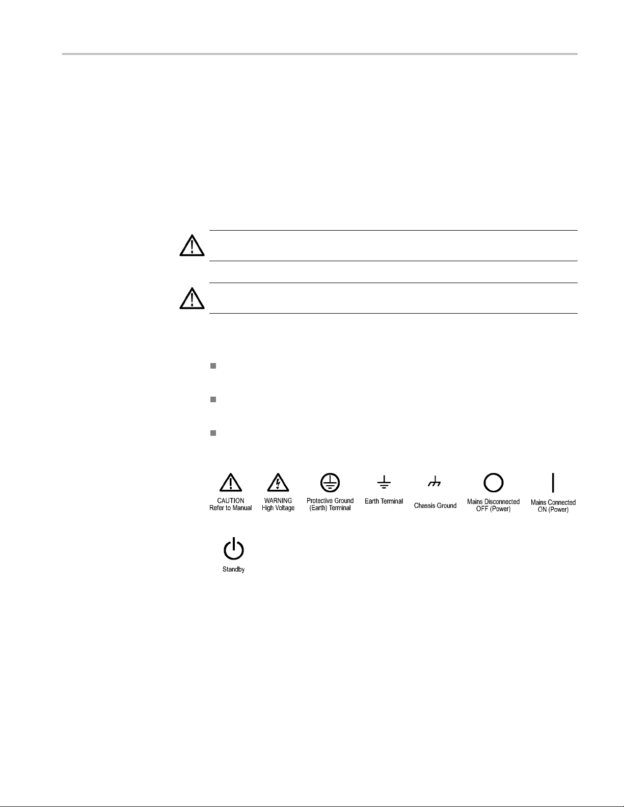
The following symbol(s) may appear on the product:
DSA8300 Digital Serial Analyzer and Modules Service Manual vii
Page 14

Service Safety Summary
Service Safet
y Summary
Only qualifie
Safety Summary and the General Safety Summary before performing any service
procedures.
Do Not Service Alone. Do not perform internal service or adjustments of this
product unless another person capable of rendering first aid and resuscitation is
present.
Disconnect Power. To avoid electric shock, switch off the instrument power, then
disconnect the power cord from the mains power.
Use Care When Servicing With Power On. Dangerous voltages or currents may
exist in
disconnect test leads before removing protective panels, soldering, or replacing
components.
To avoid electric shock, do not touch exposed connections.
d personnel should perform service procedures. Read this Service
this product. Disconnect power, remove battery (if applicable), and
viii DSA8300 Digital Serial Analyzer and Modules Se rvice Manual
Page 15

Preface
This is the service manual for the DSA8300 Digital Serial Analyzer and the
modules that install in the instrument (except for the 80A03 module).
Manual Structure
Manua
l Conventions
NOTE. The 80
servicing information.
Read this p
andwhereyoucanfind other information related to servicing this product. Read
the Introduction following this preface for safety and other important background
information needed before servicing this product.
This manual is divided into sections, whic h are made up of related subordinate
topics. These topics can be cross referenced as sections.
Be sure to read the introductions to all procedures. These introductions provide
important information needed to do the service correctly, safely, and efficiently.
This manual uses certain conventions that you should become familiar with
before beginning service.
A03 instruction manual contains its own specifications and
reface to learn how this manual is structured, what conventions it uses,
emblies and Modules
Ass
Replaceable Parts
Safety
DSA8300 Digital Serial Analyzer and Modules Service Manual ix
Throughout this manual, the term assembly appears. An assembly is composed
of electrical and mechanical assemblies, circuit c ards, interconnecting cables,
and a user-accessible front panel. References to an assembly are different
an references to a module such as “Sampling modules,” “Phase Reference
th
modules,” or “Accessory modules,” which are products installed in the instrument
compartments.
This manual refers to any field-replaceable assembly or mechanical part by its
name or generically as a replaceable part. In general, a replaceable part is any
circuit board or assembly, such as a hard disk drive, or a mechanical part, such as
I/O port connectors, that is listed in the replaceable parts list.
Symbols and terms related to safety appear in the General Safety Summary and
the Service Safety Summary found at the beginning of this manual.
Page 16

Preface
Related Documentation
The following documents relate to the instruments this service manual supports:
DSA8300 Quick Start User manual. Tektronix part number 071-2897-XX.
This document also contains specification changes when using the 82A04
Phase Reference module.
DSA8300 Specifi cations and Performance Verification manual. Tektronix
part number 077-0571-XX.
DSA8300 Online Help. An online document accessed from the instrument
Help menu.
DSA8300 Programmer Guide. An online document accessed from the
instrument Help menu.
80E01, 80E02, 80E03, 80E04, and 80E06 Electrical Sampling Modules User
manual. Tektronix part number 071-0434-XX.
80E07, 80E08, 80E09, and 80E10 Electrical Sampling Remote Modules User
manual. Tektronix part number 071-2038-XX.
80C00 Series Optical Sampling Modules User manual. Tektronix part number
071-0435-XX.
80A01 Trigger Prescale Limiting Preamplifier Module User manual.
Tektronix part number 071-0873-XX.
80A02 EOS/ESD Protection Module Instructions. Tektronix part number
071-1317-XX.
80A03 TekConnect Probe Interface Module Instructions. Tektronix part
number 071-1298-XX.
80A05 Electrical Clock Recove ry Module User manual. Tektronix part
number 071-1467-XX.
82A04 Phase Reference Module User manual. Tektronix part number
077-0345-XX.
Rackmount Kit Instructions. Te ktronix part number 071-0696-XX.
TDR Z-Meas Application Online Help. Ships with this product on a separate
disc. Provides information about this TDR Impedance Measuring application
that implements the TDR calibration procedures specified by the IPC TM-650
test method.
Fast NRZ Application Online Help. Ships with this product on a separate
disc. Provides information about this application that improves throughput
for optical eye-pattern mask testing.
x DSA8300 Digital Serial Analyzer and Modules Service Manual
Page 17

Operating Information
Page 18

Page 19
Operating Information
CAUTION. Keep the bottom of the instrument clear of obstructions to allow proper
cooling.
Windows Safe Mode
If the instrument is turned off before the operating system boots, or if you’ve
installed a third-party product with a driver that is not compatible with the
instrument start-up, Windows will open in Safe mode. The touch screen will not
operate; you must install the standard-accessory keyboard and mouse. Information
about ins
Tektronix part number 071-2897-00.
talling these accessories is in the DSA8300 Quick Start User Manual,
When you
have removed any barrier to Windows start-up, you can reboot. If
the instrument no longer boots to Safe mode, you can remove the keyboard and
mouse if desired.
WheretoFindUserInformation
CAUTION. Be sure to read all safety information, warnings, and cautions in the
manuals that relate to the information you use there.
user
Some topics of interest when servicing the product are listed in the following
le. The manuals are available at www.tektronix.com/manuals.
tab
Location of user topics
Manual Topic
DSA8300 Quick Start User Manual, Tektronix
part number 071-2897-00
Your sample-module user manual. (Module
manual part numbers are provided in the
preface o f this manual.)
Environmental requirements (site
considerations, operating requirements,
ckmount requirements)
ra
aximum configuration
M
onnecting peripherals such as monitor,
C
printer, keyboard, and mouse
Powering the instrument on and off
System hard drive rebuild
Diagram of rear-panel connectors
Installing sampling modules
Installing probes and other accessories to
the sampling modules
DSA8300 Digital Serial Analyzer and Modules Service Manual 1–1
Page 20

Operating Information
Location of user topics
Manual Topic
DSA8300 Speci
Verification manual, Tektronix part number
077-0571-00
Product software install instructions,
Tektronix p
with the product software disc.
fications and Performance
art number 071-2050-02. Shipped
System diagno
System hard drive rebuild procedure
Software r elease notes
Software installation
Operating system reinstallation
stics procedure
1–2 DSA8300 Digital Serial Analyzer and Modules Service Manual
Page 21

Theory of Operation
Page 22

Page 23

Theory of Operation
This chapter describes the electrical operation of the instrument and sampling
modules.
The instrument contains many digital logic circuits. This manual refers to these
circuits with standard logic s ymbols and terms. Unless otherwise stated, all logic
functions a
the two logic levels is the high (1) state, and the more negative level is the low (0)
state. Signal states may also be described as "true", meaning their active state,
or "false", meaning their nonactive state. The specific voltages that constitute a
high or low state vary among the electronic devices.
The instrument control system is a dual Wintel/PowerPC based processor board.
The platform features XGA resolution flat-panel display, transparent touch screen
and user front-panel with direct access to commonly used oscilloscope functions.
The inst
advanced functions.
re described using the positive-logic convention: the more positive of
rument is also equipped with a mous e and keyboard for access to more
DSA8300 Digital Serial Analyzer and Modules Service Manual 2–1
Page 24
Theory of Operation
Mainframe Ove
rview
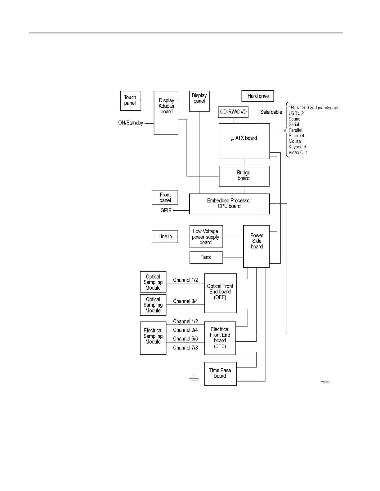
This mainframe overview describes the basic operation o f each functional circuit
block as shown in the following figure:
Figure 2-1: DSA8300 block diagram
2–2 DSA8300 Digital Serial Analyzer and Modules Service Manual
Page 25

Theory of Operation
Input Signal Path
Asignalenters
connector on a sampling module, or a real time probe connected to the sampling
module channel.
Acquisition system. The acquisition system conditions the input signals, samples
them, converts them to digital signals, and controls the acquisition process under
direction of the processor system.
The acquisition system includes the multi-source trigger, acquisition time base,
and acquisition mode generation and control circuitry. The acquisition boards
are located in the bottom compartment of the instrument and can accommodate
four small slot sampling plug-ins, two large slot plug-ins and a trigger/holdoff
subsystem. Up to eight vertical channels are accommodated simultaneously.
Channels 1, 2, 3, and 4 can be either large or small slots. The presence of an
assembly in one or both large slots displaces the small slot functionality in
the corresponding small slots. The external trigger and all small slot channels
feature a Tekprobe Level 2 probe power connector for a dditional front end signal
conditioning functions like high input-impedance real-time probes, if equipped on
the sampling module.
Processor system. The processor system contains a dual Wintel/PowerPC
The basic instrument configuration supports up to eight channels labeled Ch 1
through Ch 8, provides two external trigger inputs for direct and prescaled/clock
triggering through built-in prescaler and is able to support four optional internal
trigger sources associated with the large slot channels.
the instrument through a direct coaxial connection to the input
Display Panel
Front Panel
Color LCD display Active-matrix touch panel.
Display system. The display system sends the text and waveform information to
the display panel
Touch panel. The touch panel sends information to the processor. Any changes in
their settings are reported to the processor system.
The front panel board reads the front-panel switches and knob sensors. Any
changes in their settings are reported to the Windows system. The front panel
board also turns the LEDs on. One USB port is also accessible from the front
panel.
Front-panel menu switches are also read by the front-panel microcontroller. The
microcontroller sends any changes in menu selections to the Windows system. The
ON/STBY switch is one of the menu switches. However, it is not read by the front
panel board, but passes through the front panel board to the Wintel motherboard.
The CD-RW/DVD drive enables you to load software to customize your
instrument for your measurement needs and to save data to a writable CD.
DSA8300 Digital Serial Analyzer and Modules Service Manual 2–3
Page 26

Theory of Operation
Rear Panel
Low Voltage Power Supply
Fans
The removable h
ard drive contains the product software and operating system
software. It also provides capability to store and access waveform data. The GPIB
allows for external control of the instrument.
You can make hard copies on the GPIB and RS-232 ports. Other ports are
outputs from the ATX board: DVI-I, USB (4), sound, serial, Ethernet, mouse,
and keyboard.
The low voltage power supply is a switching power converter with active power
factor control. It supplies power to all of the circuitry in the instrument.
The principal POWER switch, located on the rear panel, controls all power to the
instrument including the Low Voltage Power Supply. The ON/STBY switch,
located on the front panel, also controls all of the power to the instrument except
for part of the circuitry in the Low Voltage Power Supply and stand-by power on
the motherboard.
The power supply sends a power fail (~PF) warning to the proces sor system if the
power is going down.
The fan assembly provides forced air cooling for the instrument.
The fans are controlled by the PPC processor.
Electrical Sampling Modules
80E01, 80E02, 80E03,
80E06, 80E07, and 80E09
Sampling Modules
The electrical sampling m odules (non-TDR capable) are one- and two-channel
sampling modules. Their basic features are listed in the following table. (The
TDR capable sampling modules are describe later.)
Electrical sampling module features
ature
Fe
Number
f
o
independent
channels
Bandwidth
Selectable
bandwidths
Signal
connectors
Remote
sampler
E01
80
122122
50 GHz 12.5 GHz 20 GHz 70 GHz 30 GHz 60 GHz
N.A. N.A. N.A. N.A.
2.4 mm
female
N.A. N.A. N.A. N.A. 2 meter
E02
80
3.5 mm
female
E03
80
3.5 mm
female
E06
80
1.85 mm
(V)
female
E07
80
20 GHz,
30 GHz
2.92 mm
(K)
female
cable
E09
80
40 GHz,
30 GHz,
60 GHz
1.85 mm
(V)
female
2 meter
cable
2–4 DSA8300 Digital Serial Analyzer and Modules Service Manual
Page 27

Theory of Operation
80E04, 80E08, and 80E10
TDR/Sampling Modules
For the two-cha
nnel modules, a single strobe delivered from the instrument
mainframe to both acquisition channels controls the timing of the strobe assertion
to both channels. If channel-to-channel deskew is zero and the channel delays (if
equipped) are matched, the sampling coincidence between channels is very close.
Acquisition deskew function is carried out either by making separate acquisitions
over individual acquisition windows or by adjusting Channel Delay (if equipped).
For the one-channel modules, an individual strobe delivered from the instrument
mainframe to the acquisition channel controls the timing of the strobe assertion
to the chan
nel. Acquisition deskew function is carried out by moving the strobe
timing for the channel to a unique acquisition window or by adjusting Channel
Delay (if equipped).
Most electrical channels feature a Tekprobe Level 2 probe power connector for
attachment of a real time probe. The control of this probe is a mainframe function.
All module calibration signals are derived from a 2.5 V precision voltage reference
internal to the sampling module. Settings derived from this reference are stored in
a nonvolatile EEPROM in the sampling module, although the responsibility for
the execution of these settings is with the mainframe.
The TDR/Sampling modules are low noise samplers, with each channel capable
of generating its own Time Domain Reflectometry (TDR) step. The basic features
of these modules are listed in the following table.
TDR sampling module features
ture
Fea
ber of
Num
independent
channels
Number of TDR
annels
ch
Bandwidth
Selectable
bandwidths
Signal connectors 3.5 mm female 2.92 mm (K) female 1.85 mm (V) female
Remote sampler N.A. 2 meter cable 2 meter cable
04
80E
222
222
0GHz
2
N.A.
08
80E
0GHz
3
20 GHz, 30 G Hz 40 GHz, 30 GHz,
10
80E
0GHz
5
50 GHz
For these modules, a single strobe d elivered from the instrument mainframe to
both acquisition channels controls the timing of the strobe assertion to both
channels. If channel-to-channel deskew is zero and the channel delays (if
equipped) are matched, the sampling coincidence between channels is very close.
Acquisition deskew function is carried out by making separate acquisitions over
acquisition windows or by adjusting Channel Delay (if equipped).
Each electrical channel features a Tekprobe Level 2 probe power connector for
attachment of a real time probe. The control of this probe is a mainframe function.
DSA8300 Digital Serial Analyzer and Modules Service Manual 2–5
Page 28

Theory of Operation
All module cali
internal to the sampling module. Settings derived from this reference are stored in
a nonvolatile EEPROM in the sampling module, although the responsibility for
the execution of these settings is with the mainframe.
When used in the acquisition mode (that is, with the TDR step generator turned
off) each channel functions as a normal sampling input. In the TDR mode, a fast
rise time step is generated internally for each channel and applied to the input
signal path for that channel. The acquisition part of the TDR/sampling module
remains functional for monitoring the primary step and its reflected components.
The sampling module provides two self-contained TDR channels. The polarity
of the output step can be selected independently for each channel. This allows
differential or common mode testing of two coupled lines as well as independent
testing of isolated lines.
Optical Sampling Modules
80CXX and 80CXX-CR optical modules share the same mechanical package and
are built with a common circuit board. D ifferent functionality within the m odules
(current and future modules) is achieved by installing different O/E modules,
filters and clock recovery boards along with setting the sampler bandwidth as
demanded. The key features supported in the module are:
bration signals are derived from a 2.5 V precision voltage reference
A one channel, low noise, adjustable bandwidth sampler allowing multiple
bandwidth settings for optimizing noise versus bandwidth demands.
An amplified or nonamplified O/E converter.
Support for internal RF switches in the signal path with a straight-through
path and three hardware-filtered reference receiver paths between the O/E
converter and the sampler.
An average optical power meter.
Integral clock recovery option with internal coaxial connection to the
mainframe trigge
Communication with the mainframe for identification, control and
calibration/compensation storage.
The "system response" depends on all of the c omponents in the signal path from
the front panel to the sampler. Bandwidth and reference receiver responses are
calibrated at the factory with a sub-picosecond optical impulse applied to the
front panel connector or with an optical heterodyne system. This ensures that all
components are included, but also means that components cannot be replaced
without performing calibration.
Compensation performs a DC transfer curve characterization for each
bandwidth/reference receiver setting. The curve data is stored in the module
EEPROM and used to generate a look-up table in the mainframe. This data
corrects for linearity, gain and offset errors in the sampler.
r, front panel clock and data output (not all have data).
2–6 DSA8300 Digital Serial Analyzer and Modules Service Manual
Page 29

Theory of Operation
Reference rece
ivers can be created in any of the following ways:
Ahardwarefilter inserted between the O/E and the sampler and dominates
the res ponse.
No filter is used, but the bandwidth of the sampler is adjusted.
The O/E bandwidth is adjusted and dominates the response.
Information about the available bandwidth and reference receiver selections, and
the method used to set the bandwidth for the optical modules is in the Optical
Sampling Module section. (See page 2-8.)
The power monitor is a second measure of the photo-diode current that is
independent of the sampler signal path. Analog circuitry continuously senses the
current flowing into the bias side of the photo diode. The signal is amplified
by a programmable gain amplifier and input to an 8-bit AD converter. The AD
2
converter and amplifier are controlled through the I
C interface. Compensation
performs two functions in the power meter: First, two offset inputs are adjusted in
the amplifier so that the signal stays in range for all of the gain settings. Next,
offset is measured for all gain s ettings and stored so it can be subtracted from the
raw measured current. Because the m easurements are made through independent
paths the power monitor is useful in debugging module/mainframe problems.
The main board of the module only provides power and control bits to the clock
recovery board. A small fraction of the input signal is split off and applied to
the clock recovery components. The type of splitter for each module is shown
in the foll
owing table.
Module optical/electrical split
Module Optical Split Electrical Split
C01
C02
C03
C04
C07
C07B
C08
C08B
C08C
C09
C11
C12
n
n
n
n
n
n
n
n
n
n
n
n
The recovered clock is routed in coaxial cable through the rear connector of the
module to the Optical Front End board in the mainframe. The Optical Front End
board has a switch that selects which modules clock is applied to the trigger. The
control signal for that switch comes from the optical module.
DSA8300 Digital Serial Analyzer and Modules Service Manual 2–7
Page 30

Theory of Operation
80C01 Optical Sampling
Module
The 80C01 modul
(1100-1650 nm) signals at 622, 2488, and 9953 Mb/s a s well as general purpose
testing up to 20 GHz optical bandwidth. Bandwidth and reference receiver
calibration is performed with a sub-picosecond optical impulse and a Fourier
transform method.
OC12: The electrical sampler is adjusted to approximately 7.5 GHz (-3 dB)
bandwidth and signal is routed through a hardware filter designed to result in
the combined system having an OC12 (STM-4) Reference Receiver response.
OC48: The electrical sampler is adjusted to 7.5 GHz (-3 dB) bandwidth and
signal is routed through a hardware filter designed to result in the combined
system having an OC48 (STM-16) Reference Receiver response. These
adjustmentsmustbemadeatthefactory.
OC192: The electric al sampler is adjusted to give the desired response,
and s ignal is not routed through any filter (signal is sent through the
straight-through path). The sampler bandwidth and response is optimized
during the calibration such that the combined system will have an OC192
(STM-64) Reference Receiver response.
12.5 GHz: The sampler bandwidth and response is set during the calibration
such that the combined system will have an Optical Bandwidth (-6 dB)
>12.5 GHz.
20 GHz: The sampler bandwidth and response is set during the calibration
such that the combined system will have an Optical Bandwidth (-6 dB)
>20 GHz.
e supports conformance testing of long wavelength
80C02 Optical Sampling
Module
The 80C02 module is optimized for testing of long-wavelength (1100-1650 nm)
signals at (9.953 Gb/s) SONET OC-192 / SDH STM-64 standards. With its
high optical bandwidth (>30 GHz) it is also well suited to general purpose
high-performance optical component testing.
OC192: The electric al sampler is adjusted to give the desired response,
and s ignal is not routed through any filter (signal is sent through the
straight-through path). The sampler bandwidth and response is optimized
during the calibration such that the combined system will have an OC192
(STM-64) Reference Receiver response.
12.5 GHz: The sampler bandwidth and response is set during the calibration
such that the combined system will have an Optical Bandwidth (-6 dB)
>12.5 GHz.
20 GHz: The sampler bandwidth and response is set during the calibration
such that the combined system will have an Optical Bandwidth (-6 dB)
>20 GHz.
30 GHz: The sampler bandwidth and response is set during the calibration
such that the combined system will have an Optical Bandwidth (-6 dB)
>30 GHz.
2–8 DSA8300 Digital Serial Analyzer and Modules Service Manual
Page 31

Theory of Operation
80C03 Optical Sampling
Module
The 80C03 modul
(700-1650 nm) signals at 1.063, 1.250, and 2.488 Mb/s as well as general purpose
testing with >2.3 GHz optical bandwidth. Its amplified optical to electrical
converter design enables the user to examine very low-level optic al signals.
OC48: The electrical sampler is adjusted to approximately 12.5 GHz (-3 dB)
bandwidth and signal is not routed through any filter (signal is sent through
the straight-through path). The O/E converter is designed by the vendor to
match the OC48 reference receiver response curve. The span adjustment
provides l
factory so that the combined system will have an OC48 (STM-64) Reference
Receiver response. This mode is synonymous with the 2.3 GHz maximum
bandwidth setting.
FC1063: The electrical sampler is adjusted and O/E converter span volta ge
are the same values as in the OC48 mode. The signal is routed through a
hardware filter designed to result in the combined system having an FC1063
(1.0625 Gb/s Fibre Channel) Reference Receiver response.
GBE: The electrical sampler is adjusted and O/E converter span voltage are
the same values as in the OC48 mode. The signal is routed through a hardware
designed to result in the combined system having an GBE (1.25 Gb/s
filter
Gigabit Ethernet) Reference Receiver response.
0C03 module can be configured with clock recovery that supports Fibre
The 8
Channel 1063 (1.063 Gb/s) and OC-48 / STM-16 (2.488 Gb/s) standards.
e supports conformance testing of both short and long bandwidth
imited adjustment of the frequency response. It is adjusted at the
80C04 Optical Sampling
ule
Mod
The 80C04 module is optimized for testing of long wavelength (1100-1650 nm)
nals at either 9.953 Gb/s or 10.664 Gb/s. With its high optical bandwidth
sig
>28 GHz, it is also well suited to general-purpose, high-performance optical
component testing.
OC192 or 10.664 Gb/s: The electrical sampler is adjusted to give the desired
response, and signal is not routed through any filter (signal is sent through
the straight-through path). The sampler bandwidth and response is optimized
during the calibration such that the combined system will have an OC192
(STM-64) or 10.66 Gb Reference Receiver response.
20 GHz: The sampler bandwidth and response is set during the calibration
such that the combined system will have an Optical Bandwidth (-6 dB)
>20 GHz.
30 GHz: The sampler bandwidth and response is set during the calibration
such that the combined system will have an Optical Bandwidth (-6 dB)
>28 GHz.
The 80C04 can be optionally configured with clock recovery (Opt. CR-1) that
supports 9.953 Gb/s telecom standards.
DSA8300 Digital Serial Analyzer and Modules Service Manual 2–9
Page 32

Theory of Operation
80C05 Optical Sampling
Module
80C06 Optical Sampling
Module
80C07 Optical Sampling
Module
The 80C05 modul
Thismoduleisintendedtobeusedasatestandmeasurementtoolforhigh
bandwidth telecommunications with its high optical bandwidth >40 GHz.
OC192: There is one Reference Receiver setup selectable for 9.95328 Gb/s
SONET/SDH standard.
There is no clock recovery option available.
The 80C06 module is designed to test long wavelength (1520-1580 nm) signals.
Thismoduleisintendedtobeusedasatestandmeasurementtoolforhigh
bandwidth telecommunications with its high optical bandwidth >55 GHz.
55 GHz: There is only a single bandwidth selection available, no Reference
Receiver setups selectable.
There is no clock recovery option available.
The 80C07 module is designed to test both long and short wavelength
(700-1650 nm) signals. This module is intended to be used as a test and
measurement tool for high bandwidth telecommunications with its high optical
bandwidth >2.3 GHz.
e is designed to test long wavelength (1520-1580 nm) signals.
80C07B Optical Sampling
Module
80C08 Optical Sampling
Module
Filtered rates are OC-3, OC-12; unfiltered rate is OC-48.
There is clock recovery option available (155/622/2488 Multi-rate).
The 80C07B module is designed to test both long and short wavelength
(700-1650 nm) signals. This module is intended to be used as a test and
measurement tool for high bandwidth telecommunications with its high optical
bandwidth >2.3 GHz.
Supported standards or data filtering rates include OC-3, OC-12, OC-48,
ENET2500/2GBE, GBE, FC1063, FC2125, and Infiniband.
Clock recovery options are available
(155/622/1063/1250/2125/2488/2500/2666).
The 80C08 module is designed to test both long and short wavelength
(700-1650 nm) signals. This module is intended to be used as a test and
measurement tool for high bandwidth telecommunications with its high optical
bandwidth >9.0 GHz.
10.0 GHz: No filter is used and the sampler bandwidth is adjusted; the O/E
bandwidth is adjusted and dominates the response (9.953/10.3125 Gb/s
Multi-rate).
There is clock recovery option available (9.953/10.3125 Gb/s Multi-rate).
2–10 DSA8300 Digital Serial Analyzer and Modules Service Manual
Page 33

Theory of Operation
80C08B Optical Sampling
Module
80C08C Optical Sampling
Module
The 80C08B modu
(700-1650 nm) signals. This module is intended to be used as a test and
measurement tool for high bandwidth telecommunications with its high optical
bandwidth >9.5 GHz.
10.0 GHz: No filter is used and the sampler bandwidth is adjusted; the O/E
bandwidth is adjusted and dominates the response (9.953/10.3125 Gb/s
Multi-rate).
Clock recovery options are available (9.953/10.3125/10.51875 Gb/s
Multi-rate).
The 80C08C module is designed to test both long and short wavelength
(700-1650 nm) signals. This module is intended to be used as a test and
measurement tool for high bandwidth telecommunications with its high optical
bandwidth >10 GHz.
10.0 GHz: No filter is used and the sampler bandwidth is adjusted;
the O/E bandwidth is adjusted and dominates the response
/10.3125/10.518/10.66/10.709/11.1/11.317 Gb/s).
(9.953
Clock recovery options are available (9.953/10.3125/10.518 Gb/s and
nuous-rate from 9.8 Gb/s to 12.6 Gb/s).
Conti
le is designed to test both long and short wavelength
80C09 Optical Sampling
Module
80C10 Optical Sampling
Module
The 80C09 module is d esigned to test long wavelength (1100-1650 nm) signals.
This module is intended to be used as a test and measurement tool for high
dwidth telecommunications with its high optical bandwidth >30 GHz.
ban
Supported standards or data filtering rates include OC-192 and FEC10.709.
Clock recovery options are available (OC-192 and FEC10.709).
The 80C10 module is designed to test long wavelength (1310 and 1550 nm)
signals. This module is intended to be used as a test and measurement tool for
high bandwidth telecommunications with its high optical bandwidth >65 GHz.
Supported standards or data filtering rates include OC-768 and FEC43.02
(G.709).
30 GHz: The sampler bandwidth and response is set during the calibration
such that the combined system will have an Optical Bandwidth (-6 dB)
>30 GHz.
65 GHz: The sampler bandwidth and response is set during the calibration
such that the combined system will have an Optical Bandwidth (-6 dB)
>65 GHz.
There is no clock recovery option available.
DSA8300 Digital Serial Analyzer and Modules Service Manual 2–11
Page 34

Theory of Operation
80C10B Optical Sampling
Module
80C11 Optical Sampling
Module
The 80C10B modu
signals. This module is intended to be used as a test and measurement tool for
high bandwidth telecommunications with its high optical bandwidth >80 GHz.
Supported standards or data filtering rates include OC-768 and FEC43.02
(G.709).
30 GHz: The sampler bandwidth and response is set during the calibration
such that the combined system will have an Optical Bandwidth (-6 dB)
>30 GHz.
65 GHz: The sampler bandwidth and response is set during the calibration
such that the combined system will have an Optical Bandwidth (-6 dB)
>65 GHz.
80 GHz: The sampler bandwidth and response is set during the calibration
such that the combined system will have an Optical Bandwidth (-6 dB)
>80 GHz.
There is no clock recovery option available.
The 80C11 module is designed to test long wavelength (1100-1650 nm) signals.
Thismoduleisintendedtobeusedasatestandmeasurementtoolforhigh
bandwidth telecommunications with its high optical bandwidth >20 GHz.
le is designed to test long wavelength (1310 and 1550 nm)
80C12 Optical Sampling
Module
Supported standards or data filtering rates include
9.953/10.31/10.518/10.66/10.71/11.1 Gb/s.
Clock recovery options are available (9.953/10.66/10.71 Gb/s and
Continuous-rate from 9.8 Gb/s to 12.6 Gb/s).
The 80C12 module is designed to test both long and short wavelength
(700-1650 nm) signals. This module is intended to be used as a test and
measurement tool for high bandwidth telecommunications with its high optical
bandwidth >10 GHz.
There are three Reference Receiver filters selectable that are customer
specified from the following list of five rates: 1FC (FC1063) for 1.0625 Gb/s
Fibre Channel, 2FC (FC2125) for 2.125 Gb/s Fibre Channel, 10GBase-X4
for 3.125 Gb/s, VSR-5 for 3.31776 Gb/s, and 4FC (FC4250) for 4.25 Gb/s
Fibre Channel. Filterless, full-bandwidth settings (8.5 GHz and 9 GHz) are
also ava ilable.
In addition, this module offers the option to support 10 Gb/s optical standards
as well. This option is mutually exclusive with the sub-10 Gb/s filter options.
The standard reference receiver filter rates offered with the Option 10G are
SONET/SDH OC-192/STM-64, 10GBase-W, 10 Gb Ethernet (9.95338 Gb/s),
10GBase-R (10.3125 Gb/s), 10G Fibre Channel (10.51875 Gb/s), G.975
FEC (10.66 Gb/s), G.709 FEC (10.71 Gb/s), 10GBE FEC (11.0957 Gb/s),
2–12 DSA8300 Digital Serial Analyzer and Modules Service Manual
Page 35

Theory of Operation
80C14 Optical Sampling
Module
80C25GBE Optical
Sampling Module
8G FibreChanne
filter settings require no hardware filters.
An electrical
the Tektronix 80A05 or 80A07 for clock recovery.
The 80C14 Series Optical Sampling Module is a high-performance optical module
that suppor
Fibre Channel and 14.063 Gb/s Infiniband.
The 80C14 s
(8.500 Gb/s), OC-192/STM-64 (9.953 Gb/s), 10GBase-W (9.953 Gb/s),
10GBase-R (10.31 Gb/s), 40GBase-R4 (10.31 Gb/s), 100GBase-SR10
(10.31 Gb/s), 10GFC (10.52 Gb/s), ITU-T G.975 FEC (10.664 Gb/s), ITU-T
G.709 (10.709 Gb/s), 10 GbE FEC (11.1 Gb/s), 10GFC FEC (11.3 Gb/s),
Super FEC (12.5 Gb/s), 16GFC (14.025 Gb/s), 14G Infiniband FDR
(14.062
Clock recovery is supported with the use of the CR175A or CR286A Clock
Recove
The 80C25GBE module is designed to test long wavelength (1310 and 1550 nm)
signals. This module is intended to be used as a test and measurement tool for
high
ts high bandwidth telecom and datacom standards, including 16 GFC
5Gb/s).
ry instrument (purchased separately).
bandwidth telecommunications with its high optical bandwidth >65 GHz.
l (8.5 Gb/s), 10G FibreChannel FEC (11.317 Gb/s). These
clock recovery output signal is provided that can be routed to
upports the following standards and data filtering rates: 8GFC
Supported standards or data filtering rates include 25.781 Gb/s 100GBase-xR4
27.739 Gb/s 100GBase-xR4 FEC.
and
65 GHz: The sampler bandwidth and response is set during the calibration
ch that the combined system will have an Optical Bandwidth (-6 dB)
su
>65 GHz.
ere is no clock recovery option available.
Th
80A01 Trigger Prescale Preamplifier Module
The 80A01 module is designed to increase the sensitivity of the prescale trigger
input of the DSA8300 to ≤200 mV
The major function block of the module is a high sensitivity, high gain RF
amplifier. The input and output to this a mplifier are routed to two identical SMA,
female connectors, labeled Input and Output at the module front panel.
The module receives power from the main instrument through a single connector
at the rear of the module. The power LED indicates the module is receiving power
through the interface connector.
p-p
.
DSA8300 Digital Serial Analyzer and Modules Service Manual 2–13
Page 36

Theory of Operation
80A02 EOS/ESD
Protection Module
The 80A02 EOS/ESD (Electrical Over Stress/Electro-Static Discharge) protection
module works with any DSA8300 instrument and provides static electricity
damage prote
elements.
The 80A02 EO
to provide static protection to a sensitive single input channel of a sampling
oscilloscope with very minimal speed degradation.
The 80A02 EOS/ESD module is designed to work with either the Tektronix P8018
probe for manual test station static protection as well as automated test stations.
ction to vulnerable sampling head input stages and/or other sensitive
S/ESD module has a 26 GHz bandwidth, making it possible
80A05 Electrical Clock Recovery M odule
The electrical clock recovery module is capable of performing clock recovery on
the input signal (signal input must meet data rate and format requirements), and
provides this signal as a trigger source to the DSA8300.
Front panel connectors provide a replica of the recovered clock signal.
Themoduleusesoneoftwoseparateclock recovery circuits dependant on the
specified data rate. The single-ended or complementary input signals are split
with a 1:2 divider and routed to the two circuits.
The low bandwidth circuit recovers clock and data from input data in the 50 Mb/s
to 2.7 Gb/s range. The recovered clock from this circuit is routed directly to the
front panel and internal trigger.
The high bandwidth circuit recovers clock a nd data from input data in the 2.7 Gb/s
to 12.6 Gb/s range. The recovered clock to the front panel and internal trigger
gnals are always clock/16.
si
With option 10G, the 10G recovered clock is also routed to the front panel.
There is one front panel indicator LED - Clock Recovery Enable. It indicates the
clock recovery circuitry is on and programmed to the requested bit rate.
2–14 DSA8300 Digital Serial Analyzer and Modules Service Manual
Page 37

Theory of Operation
82A04 Phase Re
ference Module
The 82A04 Phase Reference Module is designed to decrease horizontal position
uncertainty with data signals, when a r eference clock signal synchronized to the
data signal,
both channels in that slot.
The Phase Co
unit circle location information for the phase of the data sample, and triggered,
where the module, in conjunction with the trigger signal, provides both base
positioning, and refined positioning, for the data sample.
The input is precision 1.85 mm. Phase correction works over the range of 2.5 GHz
- 25 GHz (82A04), or 2.5 GHz - 60 GHz (82A04-60G). The LED indicates the
module is being utilized for phase correction.
is available. It consumes a small slot, and displaces operation of
rrection modes available are free run, where the module provides
DSA8300 Digital Serial Analyzer and Modules Service Manual 2–15
Page 38

Theory of Operation
2–16 DSA8300 Digital Serial Analyzer and Modules Service Manual
Page 39

Adjustment Procedures
Page 40

Page 41

Adjustment Procedures
This section contains an adjustment procedure for your instrument. The purpose
of this procedure is to return the instrument conformance to its specifications.
Adjustment interval. The voltage and timing references inside the instrument
are very sta
time you should perform the Adjustment Procedures is if the instrument fails
any of the mainframe performance verification checks provided in the DSA8300
Specifications and Performance Verification manual.
Adjustment environment. The instrument must be adjusted in a 20°C to 30 °C
ambient t
up at least 20 minutes in this environment b efore you begin the adjustment
procedure.
Required Equipment
The adjustment procedure requires the specific test equipment and materials listed
in the following table.
ble over time and should not need routine adjustment. The only
emperature environment. The instrument and signal source must warm
Category Specific equipment required Quantity
Signal source Signal generator 50 MHz to 1 GHz,≤ 1 ppm frequency accuracy
Frequency counter Frequency resolution 12 digits 1 ea
Meter Digital Multimeter, with 6.5 plus digits 1 ea
Instrument controller (only
one of these configurations
required)
Divider
Adapter
Adapter
Adapter
Coaxial cables 50Ω, male-to-male SMA connectors
GPIB cables GPIB cable, 1 m min length, Tektronix part number 002-0991-01
1
Depending on other USB devices attached to the instrument, a USB hub may also be required. Consult your National
Instruments documentation for more information.
PC-compatible computer with National Instruments GPIB Controller card and
software, running Windows 95/98 or NT
National Instruments USB GPIB Controller card for Windows 98 and National
Instruments NI-488.2 for Windows software (to install in the instrument)
Power, 50Ω, SMA "T" male Tektronix 015-0565-00
SMA "T", male to 2 SMA female Tektronix part number 015-1016-00
SMA male to BNC female, Tektronix part number 015-0554-00
BNC to dual banana plug, Tektronix part number 103-0095-00
1ea
1ea
1ea
1ea
1ea
1ea
1ea
3ea
1ea
DSA8300 Digital Serial Analyzer and Modules Service Manual 3–1
Page 42

Adjustment Procedures
Equipment Hookup
1. Connect the equipment as shown in the following figure:
2. Set the National Instruments GPIB Interface command software to allow
GPIB communications between the PC controller and DSA8300, device
under test (DUT).
3. Allow the test equipment and DUT to warm up for at least 20 minutes before
starting the adjustment procedures.
Main Instrument Adjustments
DC Calibrator Adjust
1. Use the equipment connection shown in the preceding figure. Make sure that
the equipment has warmed up for at least 20 minutes.
2. Run the compensation routine.
3. Verify communication between the controller and DUT by entering the
following GPIB command:
The instrument should respond with Tektronix and Firmware Version.
4. Turn off the instrument cal constant protection by entering the following
GPIB command:
5. Set the instrument DC calibrator offset cal constant to 0 by entering the
following GPIB command:
6. Wait 8 seconds, and then set the instrument DC calibrator Lsb cal constan
to 1.0 by entering the following GPIB command:
"DcCalLsbAdj",1.0
*IDN
SYST:PROT OFF
CALCOMP:DOUBLE "DcCalOffsetAdj",0.0
t
CALCOMP:DOUBLE
7. Wait 8 seconds, and then set the instrument DC calibrator output to 0 Volts by
entering the following GPIB command:
8. Record the DMM reading.
3–2 DSA8300 Digital Serial Analyzer and Modules Service Manual
CALIBRATE:DCCALIBRATOR 0.0
Page 43

Adjustment Procedures
9. Set the instrum
reading by entering the following GPIB command:
"DcCalOffsetAdj",(-1.0 * the DMM reading)
ent DC calibrator o ffset cal constant to -1 * DMM
CALCOMP:DOUBLE
Example: CALCOMP:DOUBLE "DcCalOffsetAdj", 3.2e-4
10. Set the inst
command:
11. Record the D
rument calibrator to 1.0 V by entering the following GPIB
CALIBRATE:DCCALIBRATOR 1.0
MM reading (reading1).
12. Set the instrument calibrator to -1.0 V by entering the following GPIB
ALIBRATE:DCCALIBRATOR -1.0
command:
C
13. Record the DMM reading (reading2).
14. Calculate the cal constant using the following equation: (–1.0 * Reading2
+ Reading1) ÷ 2.
15. Set the instrument calibrator Lsb cal constant by entering the following
GPIB command:
calcul
ated in previous step)
CALCOMP:DOUBLE "DcCalLsbAdj", (cal constant
16. Wait 8 seconds, and then save the DC adjustments by entering the following
GPIB c
ommand:
CAL:SAVE:FACT:MAIN
17. Update the mainframe calibration time/date/temperature stamp by entering
ollowing GPIB command:
the f
CAL:UPDATEINFO:MAIN
DC Calibrator Adjust
Verification
18. Turn on the instrument cal constant protection by entering the following
com
mand:
SYST:PROT ON
To verify that the DC calibration adjustment was successful, complete the
lowing:
fol
1. Set the instrument DC calibrator to -1.0 V by entering the following GPIB
mmand:
co
CALIBRATE:DCCALIBRATOR -1.0
2. Verify that the DMM reads -1.0 V ±1 mV
3. Set the instrument DC calibrator to 1.0 V by entering the following GPIB
command:
CALIBRATE:DCCALIBRATOR 1.0
4. Verify that the DMM reads 1.0 V ±1 mV
5. Set the instrument DC calibrator to 0.0 V by entering the following GPIB
command:
CALIBRATE:DCCALIBRATOR 0.0
6. Verify that the DMM reads 0.0 V ±0.1 mV
DSA8300 Digital Serial Analyzer and Modules Service Manual 3–3
Page 44

Adjustment Procedures
Internal 10 MHz Adju st
Connect the DSA
8300 to a signal generator and frequency counter as shown
in the following figure:
1. Set the signal generator as follows
Frequency to 1 GHz
Amplitude to 1.0 V peak to peak
Output to on
2. Set the frequency counter as follows:
Frequency to 200 kHz
Number of digit
sto9
3. Set the DSA8300 as follows:
Trigger source to TDR
Clock rate to 200 kHz
TDR Trigger mode to External (select Advance Trigger mode, and then
select External Trigger for TDR mode)
4. Enter the following GPIB command to turn the instrument cal constant
protection off:
“SYST:PROT OFF”
5. Set the calibration value to the default by entering the following GPIB
command:
“CALCOMP:DOUBLE "Internal10MHzRefFreq",
10e6
6. Measure the TDR Clock Out frequency (Reading 1).
7. Set the DSA8300 trigger mode to Internal.
8. Measure the TDR Clock Out frequency (Reading 2).
9. Enter the following GPIB command:
“Internal10MHzRefFreq”,
(Reading2/Reading1 * 10M)
“CALComp:DOUBLE
3–4 DSA8300 Digital Serial Analyzer and Modules Service Manual
Page 45

Adjustment Procedures
10. Measure the TDR
Clock Out frequency. (Recheck)
11. Verify that the 10 MHz measurement is within 2 kHz.
12. Save the mainframe factory calibration constants by entering the following
GPIB command:
“CAL:SAV:FACTORY:MAIN”
13. Update the mainframe calibration time/date/temperature stamp by entering
the following GPIB command:
“CAL”UPDATEINFO:MAIN”
14. Enter the following GPIB command to turn the instrument cal constant
protection on:
SYST:PROT ON
End of Procedure
DSA8300 Digital Serial Analyzer and Modules Service Manual 3–5
Page 46

Adjustment Procedures
3–6 DSA8300 Digital Serial Analyzer and Modules Service Manual
Page 47

Maintenance
Page 48

Page 49

Maintenance
This section contains the information needed to do periodic and corrective
maintenance on the mainframe, electrical modules, and optical modules, as well
as repackaging instructions for returning the products to Tektronix for service.
Preventing
ESD
Before servicing this product, read the General Safety Summary and Service
Safety Summary at the front of the manual, and familiarize yourself with the
following
CAUTION. Electrostatic discharge can damage any semiconductor component
in this instrument.
When performing any service that requires internal access to the instrument,
adhere to the fol
their components due to electrostatic discharge:
1. Minimize handl
2. Transport and store static-sensitive assemblies in their static protected
3. Discharge th
4. Do not place anything capable of generating or holding a static charge on the
electrostatic discharge (ESD) information.
lowing precautions to avoid damaging internal assemblies and
ing of static-sensitive circuit boards and components.
containers or
boards.
wrist strap while handling these assemblies. Service static-sensitive
assemblies only at a static-free w ork station.
work station surface.
on a metal rail. Label any package that contains static-sensitive
e static voltage from your body by wearing a grounded antistatic
5. Handle circuit boards by the edges when possible.
6. Do not sli
7. Avoid handling circuit boards in areas that have a floor or work-surface
coverin
de the circuit boards over any surface.
g capable of generating a static charge.
Inspection and Cleaning
tion and cleaning are done as preventive maintenance. Preventive
Inspec
maintenance, when done regularly, may prevent instrument malfunction and
enhance its reliability.
Preventive maintenance consists of visually inspecting and cleaning the
instrument and using general care when operating it.
DSA8300 Digital Serial Analyzer and Modules Service Manual 4–1
Page 50

Maintenance
General Care
Flat Panel Display Cleaning
How often to do m
the instrument is used. A proper time to perform preventive maintenance is just
before instrument adjustment.
The cabinet h
place when operating the instrument.
WARNING. To avoid personal injury due to electric shock, power off the instrument
and disconnect it from line voltage before performing any procedure that follows.
The mainframe display is a soft plastic display and must be treated with care
during cleaning.
CAUTION. Improper cleaning agents or methods can damage the flat panel
display.
To avoi
to clean the display surface.
Do not s
Do not scrub the display with excessive force.
d damage, do not use abrasive cleaners or commercial glass cleaners
pray liquids directly on the display surface.
aintenance depends on the severity of the environment in which
elps keep dust out of the instrument and should normally be in
Exterior Cleaning
Clean the flat-panel display surface by gently rubbing the display with a
clean-room wipe (such as WypAll Medium Duty Wipes, #05701, available from
erly-Clark Corporation).
Kimb
If the display is very dirty, moisten the wipe with distilled water or a 75%
propyl alcohol solution and gently rub the display surface. Avoid using excess
iso
force or you may damage the plastic display surface.
CAUTION. To prevent getting moisture inside the instrument during external
cleaning, use only enough liquid to dampen the cloth or applicator.
Do not use chemical cleaning agents that might damage the plastics used in
his instrument. Use only deionized water when cleaning the menu buttons or
t
front-panel buttons. Use a 75% isopropyl alcohol solution as a cleaner and
rinse with deionized water. Before using any other type of cleaner, consult your
Tektronix Service Center or representative.
4–2 DSA8300 Digital Serial Analyzer and Modules Service Manual
Page 51

Maintenance
Exterior Inspection
Clean the exter
ior surfaces of the chassis with a dry lint-free cloth or a soft-bristle
brush. If any dirt remains, use a cloth or swab dipped in a 75% isopropyl alcohol
solution. Use a swab to clean narrow spaces around controls and c onnectors. Do
not use abrasive compounds on any part of the chassis that might damage the
chassis.
Clean the On/Standby switch using a dampened cleaning towel. Do not spray or
wet the switch directly.
Use the following table to inspect the outside of the instrument for damage or
missing parts. Immediately repair defects that could cause personal injury or lead
to further damage to the instrument.
External inspection checklist
Item Inspect for Repair action
Cabinet, front panel, and
cover
Front-panel knobs Missing, damaged, or loose
Connectors
80C0X male fiber
connections
Carrying handle and cabinet
feet
Accessories
Cracks, scratches,
deformations, damaged
hardware.
knobs.
Broken shells, cracked
insulation, and deformed
contacts. Dirt in connectors.
Lint or dust on all male fiber
connections.
Correct operation. Repair or replace defective
Missing items or parts of
items, bent pins, broken or
frayed cables, and damaged
connectors.
Repair or replace defective
assembly.
Repair or replace missing or
defective knobs.
Repair or replace defective
assemblies. Clear or wash
out dirt.
Clean all male fiber
connections with a lint-free
cleaning cloth.
assembly.
Repair or replace damaged
or missing items, frayed
cables, and defective
assemblies.
Interior Inspection
To access the inside of the instrument for inspection and cleaning, refer to the
removal and installation procedures. (See page 4-5, Removal and Installation.)
Inspect the internal portions of the instrument for damage and wear, as shown in
the following table. Repair defects immediately.
CAUTION. To prevent damage from electrical arcing, make sure that the circuit
boards and components are dry before applying power to the instrument.
NOTE. If you repair or replace any circuit board, check to see if it is necessary to
adjust the instrument. (See Table 4-4 on page 4-58.)
DSA8300 Digital Serial Analyzer and Modules Service Manual 4–3
Page 52

Maintenance
Interior Cleaning
Internal inspe
Item Inspect for Repair action
Circuit board
Resistors Burned, cracked, broken, blistered
Capacitors
Wiring and cables Loose plugs or connectors.
Chassis Dents, deformations, and
ction checklist
s
Loose, broken, or corroded solder
connections.
boards. Burned, broken, or
cracked circuit-run plating.
condition.
Damaged or leaking cases.
Corroded solder on leads or
terminals.
Burned, br
damaged h
Burned circuit
oken, or frayed wiring.
ardware.
Remove and replace
damaged circu
Remove and replace
damaged circuit board.
Remove and replace
damaged circuit board.
Firmly seat connectors.
Repair or r
modules with defective
wires or cables.
Straighten, repair,
or replac
hardware.
it board.
eplace
e defective
1. Blow off dust with dry, low-pressure, deionized air (approximately 9 psi).
2. Remove any remaining dust with a lint-free cloth dampened in isopropyl
alcohol (75% solution) and rinse with warm deionized water. (A cotton-tipped
applicator is useful for cleaning in narrow spaces and on circuit boards.)
Lubrication
NOTE. If, after performing steps 1 and 2, an assembly is clean upon inspection,
skip the remaining steps.
3. Gain access to the parts to be cleaned by removing easily accessible shields
and panels. (See page 4-5, Removal and Installation.)
4. Spray wash dirty parts with the isopropyl alcohol and wait 60 seconds for the
majority of the alcohol to evaporate.
5. Use hot (120 °F to 140 °F) deionized water to thoroughly rinse them.
6. Dry all parts with low-pressure, deionized air.
7. Dry all components and assemblies in an oven or drying compartment using
low-temperature (125 °F to 150 °F) circulating air.
There is no periodic lubrication required for this instrument.
4–4 DSA8300 Digital Serial Analyzer and Modules Service Manual
Page 53

Removal and Installation
WAR NI NG . Before performing any procedure in this section, disconnect the power
cord from the
or death.
Only Qualified personnel should perform service procedures. Before performing
this procedure, read the General and Service Safety summaries at the beginning
of this manual. To prevent possible injury to service personnel or damage to
electrical components, read Preventing ESD. (See page 4 -1.)
NOTE. Read the cleaning procedure before disassembling the instrument for
cleaning.
If you replace any circuit board, check to see if it is necessary to adjust the
instrument. (See Table 4-4 on page 4-58.)
Removal and Installation
line voltage source. Failure to do so could cause serious injury
Required Equipment
Most assemblies in this instrument can be removed with a screwdriver handle
mounted with a size T-15, Torx® screwdriver tip. Use this tool whenever a
procedure step instructs you to remove or install a screw unless a different size
screwdriver is specified in that step.
Table 4-1: Required equipment for Removal and Replacement
Item No. Name Description Part number
1
2
3T-10Torxtip
4T-15Torxtip
5
6
7
8
9 Angle-Tip Tweezers
10
Screwdriver handle Accepts Torx®-driver bits General Tool: 620-440
Screwdriver handle, extended
length, 10.5 to 12 inches
T-20 Torx tip
3/16 inch socket tip Used for removing the 3/16 inch hex posts from the
1/8 inch flat-bladed screwdriver Screwdriver for unlocking cable connectors. Standard tool
#0 phillips screwdriver Screwdriver for removing small phillips screws, CD
3/16 inch open-end wrench
Accepts Torx®-driver bits and 3/16 socket tip. Used
for removing the T-10 screws and 3/16 inch hex posts
from the electrical and optical module slots.
Torx®-driver bit for T-10 size screw heads, used for
removing the electrical or optical module chassis.
Used for removing most the screws. Torx®-driver bit
for T-15 size screw heads.
Used for removing the handle hardware. Torx®-driver
bit for T-20 size screw heads.
electrical and optical module slots.
and hard drive.
Used to remove front panel knobs. Standard tool
Used to remove the rear panel nut posts.
Standard tool or Xcelite
99X10 V N/S#48706
General Tool: 640-235
General Tool: 640-247
General Tool: 640-250
Standard tool
Standard tool
Standard tool
DSA8300 Digital Serial Analyzer and Modules Service Manual 4–5
Page 54

Removal and Installation
Table 4-1: Required equipment for Removal and Replacement (cont.)
Item No. Name Description Part number
11
12
5/16 inch open-end wrench
Coaxial cable connector tool Used to remove coaxial connectors from
Used to remove the rear panel nut posts.
d-subminiature connector housings.
Standard tool
Amp: 58095-1
External Assemblies
WARNING. Before performing any procedure in this section, disconnect the power
cord from the line voltage source. Failure to do so could cause serious injury
or death
.
Figure 4-1: External assemblies
4–6 DSA8300 Digital Serial Analyzer and Modules Service Manual
Page 55

Removal and Installation
Line Fuses and AC Power
Cord
You will need a fl
CAUTION. Power off the instrument before servicing the line fuses or power cord.
Power off the instrument using the Windows shut down procedure, and then turn
off the power switch located on the rear of the instrument (or remove the power
cord). Powering down the instrument without using the Windows shut down
procedure c
1. Power off the instrument using the Windows shut-down process, and then
push the re
power from the mainframe.
2. Place the
you. Locate the two line fuse caps and the AC power cord near the center
of the rear panel.
3. To remove line fuses: Remove both fuse caps by turning them
counterclockwise using a flat-bladed screwdriver, and remove the line fuses.
Reverse the procedure to reinstall.
4. To remove line cord: Disconnect the AC power cord from the rear-panel
connector to remove the AC power source.
at-bladed screwdriver.
an corrupt the software on the hard disk.
ar panel power switch or disconnect the AC power cord, to remove
bottom of the instrument on the work surface, with the rear facing
DSA8300 Digital Serial Analyzer and Modules Service Manual 4–7
Page 56

Removal and Installation
Front-Panel Knobs
You will need an
NOTE. If you are not removing the front panel, you do not need to remove the
front-panel knobs; you can proceed to trim removal.
1. To remove a knob:
a. Hold the kno
front panel about 1/4 inch to create some clearance between the base of
the knob and the front panel.
b. Insert the angled-tip tweezers between the knob and front panel and use
them to remove the knob. (See Figure 4-2 on page 4-8.)
c. For replacement knob part numbers, refer to the exploded view and
replaceable parts table. (See Figure 5-3 on page 5-9.)
gled-tip tweezers.
bthatyouwanttoremoveandpullitstraightoutfromthe
Figure 4-2: Knob removal
CAUTION. To prevent damage to the encoders located on the circuit board, apply
pressure to the backs of the encoders while pushing the knob on the shaft.
3. To reinstall a knob:
lign the knob to the shaft.
a.A
b. While applying pressure to the back of the encoder, push the knob in
until it snaps.
4–8 DSA8300 Digital Serial Analyzer and Modules Service Manual
Page 57

Removal and Installation
Trim and Carrying Handle
You will need a T
1. To remove the top cover trim:
a. Remove the ac
b. Remove the four T-15 Torx drive screws that attach the top cover trim to
the instrum
the top cover. (See Figure 5-1 on page 5-5.)
c. Hold the ba
to release it from the front panel trim.
d. Pull the f
2. To remove the carrying handle and the right and left side trim panels:
a. Remove the two T-20 Torx drive screws that attach the handle to the
instrument. Remove the handle from the instrument.
b. Slide the side trim panels toward the rear of the instrument allowing the
tabs to clear the cover openings, then pull out to remove the panels from
the ins
3. To remove the front panel trim:
a. Hold the trim ring by its top edge and pull toward you to detach the three
plastic snaps. (Alternatively, you can use a flat-bladed screwdriver or
othe
-15 Torx driver and a T-20 Torx driver.
cessory pouch; it snaps off. (See Figure 4-1 on page 4-6.)
ent. The T-15 Torx drive screws also attach the snap studs to
ck of the top cover trim and swing it upward and toward you
ront cover trim away from you and remove it from the instrument.
trument.
r small prying tool to help you detach the snaps.)
b. Swing the bottom of the ring up and off the front panel.
4. To remove the acquisition trim:
a. Remove the six T-15 Torx drive screws that attach the acquisition trim to
the instrument. (See Figure 5-1 on page 5-5.)
b. Remove the knobs from the electrical and optical ejector levers (hold the
knobs with your fingers and pull straight out). (See Figure 4-19.)
c. Remove the acquisition trim from the instrument.
CAUTION. Over-tightening the handle screws may cause the handle to break off
from the cabinet. Use a torque wrench to tighten the screws to 8-10 in.lb.
5. To reinstall the covers and handle: Reve rse the steps. Use a torque wrench to
tighten the handle screws to 8–10 in. lb.
DSA8300 Digital Serial Analyzer and Modules Service Manual 4–9
Page 58

Removal and Installation
Bottom Cover
Left and Right Covers
You will need a T
1. To remove the bottom cover: (See Figure 4-1 on page 4-6.)
a. Place the top of the instrument on the work surface, with the bottom
facing you.
b. Remove the five T-15 Torx drive screws that attach the bottom cover to
the instrument. (See Figure 5-1 on page 5-5.)
c. Remove the bottom cover from the instrument.
2. To rein s ta
You will need a T-15 Torx driver.
1. To access the covers, remove these assemblies:
Trim (all) (See page 4-9.)
Bottom
2. Remove the left and right covers as follows:
NOTE.
mounting hole.
All mounting screw holes are indicated by a star etched around the
-15 Torx driver.
ll the bottom cover: Reverse the steps.
cover(Seepage4-10.)
a. Plac
b. Rem
c. Re
d.P
e. Pull the top-left c over upward and slide to the left to remove from the
CAUTION. Be careful not to bind or snag the covers on the internal cabling of
the instrument as you remove or install the covers.
3. To reinstall the left and right covers: Reverse the steps.
e the rear of the instrument o n the work surface, with the front facing
you.
ove the thirteen T-15 Torx drive screws that attach the covers to the
top and both sides of the chassis. (See Figure 5-1 on page 5-5.)
move the nine T-15 Torx drive screws that attach the covers to the
bottom of the chassis.
ull the bottom-right c over down and slide to the right to remove from
the instrument.
instrument.
4–10 DSA8300 Digital Serial Analyzer and Modules Service Manual
Page 59

Internal Assemblies
Removal and Installation
Before removing internal assemblies, you must remove the e xternal assemblies.
(See page 4-6, External Assemblies.)
Figure 4-3: I nternal assemblies
DSA8300 Digital Serial Analyzer and Modules Service Manual 4–11
Page 60

Removal and Installation
Front-Panel Assembly
You will need a fl
USB port in place, and a 1/8 inch flat-bladed screwdriver.
1. To access the a
Front-Panel trim (See page 4-9.)
CD-RW/DVD drive and trim (See page 4-22.)
2. To remove the Front-Panel assembly: (See Figure 4-3 on page 4-11.)
a. Place the bottom of the instrument on the work surface, with the front
panel facing you.
b. Remove the six T-15 Torx drive screws that attach the Front-Panel
assembly to the front chassis. (See Figure 5-3 on page 5-9.)
c. Hold the bottom of the Front-Panel assembly and pull it toward you
until it catches.
d. From the side, insert the tip of a flat-blade screwdriver directly above the
USB port and below the Front-Panel assembly. There is a piece of flexible
metal there that keeps the front panel from slipping over the USB port.
e. Push up on the flexible piece of metal as you pull the Front-Panel
assembly forward and away from the instrument.
at-bladed screwdriver to hold up the metal tab that holds the
ssembly, remove these assemblies:
f. Use the1/8 inch flat-bladed screwdriver to carefully lift up the J1 cable
connector lock. Pull up on the J1 flex cable to disconnect it from the
display module assembly. (See Figure 4-4 on page 4-13.) Note the
ition of the pin 1 index mark on the connector and the black stripe
pos
on the cable for later reassembly.
g. Pu
3. To reinstall the Front-Panel assembly: Reverse the steps.
ll the Front-Panel assembly forward and remove it from the instrument.
4–12 DSA8300 Digital Serial Analyzer and Modules Service Manual
Page 61

Removal and Installation
Figure 4-4: J1 flex cable connector removal
Front Panel Board
You wil
1. To access the board, remove these assemblies:
2. To r
3. To reinstall the Front-Panel board: Reverse the steps. Verify that the plastic
l need a small flat-bladed screwdriver for prying, and a T-15 Torx driver.
Front-Panel knobs (See page 4-8.)
Front-Panel trim (See page 4-9.)
CD-RW/DVD drive and trim (See page 4-22.)
Front-Panel assembly (See page 4-12.)
emove the Front Panel circuit board: (See Figure 4-3 on page 4-11.)
(See Figure 5-3 on page 5-9.)
a. Re
board to the Front-Panel assembly.
b. Pr
in the pry point access holes to pry the board up from the assembly.
c.R
bezel is flush against the sheet metal. If it is not, the board might not be seated
properly over the plastic posts.
move the eight T-15 Torx drive screws that attach the Front-Panel
y the board up off the alignment studs. Place a flat bladed screwdriver
emove the board from the assembly.
DSA8300 Digital Serial Analyzer and Modules Service Manual 4–13
Page 62

Removal and Installation
Front Panel Keypad
You will need a p
1. To access the assembly, remove these assemblies:
Front-Panel knobs (See page 4-8.)
Front-Panel trim (See page 4-9.)
CD-RW/DVD drive and trim (See page 4-22.)
Front-Panel assembly (See page 4-12.)
Front-Panel board (See page 4-13.)
CAUTION. When removing or installing the keypad, make sure you do not
touch the switch contact with your fingers. The oils in your fingers will
degrade or damage the switch contacts. To help prevent damage to the keypad
use cotton gloves when removing or installing the keyboard pad.
2. To remove the Front Panel keypad:
a. Use the tweezers to pull on each of the keypad support guides and separate
the keypad from the Front-Panel board.
b. Remove the keypad from the Front-Panel b oard. (See Figure 5-3 on
page 5-9.)
air of tweezers or equivalent tool.
Display Assembly
3. To reinstall the front panel keypad: Reverse the steps. Make sure that the
keypad is properly aligned on the Front-Panel board and that the ribbon cable
is routed correctly when installing the Front-Panel in the chassis. Refer to
cable connections table for information about where to connect cables.
the
(See Table 5-1.)
You will need a T-15 Torx driver.
OTE. You can replace the entire Display assembly. You can also replace the
N
Display Adapter circuit board individually (it is also a part of the Display
assembly).
Other components that make up the Display assembly (such as the LCD display
and the Standby/On switch flex circuit) cannot be individually ordered or replaced.
If there is a problem with one of these components, return the instrument to
Tektronix for repair. See the Contacting Tektronix information at the front of
this manual.
4–14 DSA8300 Digital Serial Analyzer and Modules Service Manual
Page 63

Removal and Installation
1. To access the as
Front-Panel trim (See page 4-9.)
Toptrim(Seepage4-9.)
2. To remove the Display assembly: (See Figure 4-5 on page 4-16.)
a. Place the bottom of the instrument on the work surface, with the front
panel facing you.
b. Remove the four T-15 Torx drive screws that attach the Display assembly
to the chassis.
c. Hold the top and bottom edges of the Display assembly and pull forward
far enough to allow a ccess to the ribbon cable connector.
d. Disconnect the J2 and J3 ribbon cables from the Display assembly.
CAUTION. Do not set the Display assembly on a work surface. Sliding the
instrument over the edge of the work surface could break off the Standby/On
switch assembly.
sembly, remove thes e assemblies:
DSA8300 Digital Serial Analyzer and Modules Service Manual 4–15
Page 64

Removal and Installation
e. Remove the Disp
f. To reinstall the Display assembly: Reverse the steps. Refer to the cable
connections t
Table 5-1 .)
g. To rei n s tal
connections table for information about where to connect cables. (See
Table 5-1 .)
l the Display assembly: Reverse the steps. Refer to the cable
lay assembly from the instrument.
able for information about where to connect cables. (See
Figure 4-5: Display assembly removal
Display Adapter Board
4–16 DSA8300 Digital Serial Analyzer and Modules Service Manual
You will need a T-15 Torx driver.
1. To access the board, remove these assemblies:
Display assembly (See page 4-14.)
2. To remove the Display Adapter Board from the Display assembly:
a. Disconnect the cables from the Display Adapter board. (See Figure 4-6.)
b. Remove the four T-15 Torx drive screws that attach the Display Adapter
board to the Display assembly. (See Figure 5-3.)
c. Remove the Display Adapter board from the Display assembly.
3. To reinstall the Display Adapter board: Reverse the steps. (See Figure 4-7.)
Page 65

Removal and Installation
Figure 4-6: Display adaptor board removal
DSA8300 Digital Serial Analyzer and Modules Service Manual 4–17
Page 66

Removal and Installation
re 4-7: Display adaptor board replacement
Figu
Standby/On Switch Flex
cuit
Cir
4–18 DSA8300 Digital Serial Analyzer and Modules Service Manual
The Standby/On switch flex circuit is a part of the Display assembly, and is not
ividually customer-replaceable. If this component must be replaced, you
ind
must return the instrument to Tektronix for repair. See the Contacting Tektronix
information at the front of this manual. For reference, refer to the exploded view.
(See Figure 5-3.)
Page 67

Removal and Installation
USB Assembly
You will need a T
1. To remove the USB assembly: (See Figure 4-8 on page 4-19.)
a. Place the bottom of the instrument on the work surface, with the front
panel facing you.
b. Detach the J1 cable.
c. Remove the T
d. Pull the USB assembly toward you to detach it from the instrument.
2. To reinstall the USB assembly: Reverse the steps. Refer to the cable
connections table for information about where to connect cables. (See
Table 5-1
-15 Torx driver.
-15 Torx drive screw.
.)
Figure 4-8: USB assembly removal
DSA8300 Digital Serial Analyzer and Modules Service Manual 4–19
Page 68

Removal and Installation
Hard Disk Drive
You will need a #
CAUTION. Do not remove the replaceable hard disk drive when the mainframe is
powered on; if you do so, damage can occur to the drive and mainframe. Power
off the instrument and then turn off the power switch located on the rear of the
instrument (or remove the power cord).
2. To remove the hard disk drive assembly:
a. Verify that the chassis is powered down.
b. Place the
panel facing you.
c. Locate th
(See Figure 4-3 on page 4-11.)
d. Remove t
assembly.
e. Hold th
3. To remove the hard disk drive from the assembly: (See Figure 4-9 on
-21.)
page 4
0 Phillips screwdriver.
bottom of the instrument on the work surface, with the rear
e hard disk drive assembly on the rear panel of the instrument.
he two thumbscrews from the front of the hard disk drive
e hard disk drive assembly and slide it out of the instrument.
a. Remove the four #0 Phillips screws that fasten the hard disk drive to the
ridge.
cart
b. Carefully remove the hard disk drive from the cartridge.
4. To reinstall the hard disk drive:
a. Verify that the chassis is powered down.
b. Install the hard disk drive into the cartridge.
c. Slide the assembly into the instrument.
nstall the two thumbscrews to attach the ass embly to the instrument.
d.I
Refer to the cable connections table for information about where to connect
cables. (See Table 5-1.)
4–20 DSA8300 Digital Serial Analyzer and Modules Service Manual
Page 69

Removal and Installation
Figure 4-9: Hard disk drive removal
DSA8300 Digital Serial Analyzer and Modules Service Manual 4–21
Page 70

Removal and Installation
CD-RW/DVD Drive
Assembly
You will need a #
1. To access the assembly, remove these assemblies:
Trim (all) (See page 4-9.)
Bottomcover(Seepage4-10.)
Left and right covers (See page 4-10.)
2. To remove the CD-RW/DVD disk drive assembly: (See Figure 4-3 on
page 4-11.) (See Figure 4-10 on page 4-22.)
a. Place the instrument bottom on the work surface, with the front panel
facing you.
b. Remove the two Phillips screws that hold the CD-RW/DVD drive trim to
the mounting frame and remove the trim.
c. Place one thumb on each side of the front of the CD-RW/DVD drive and
your forefingers on the back of the drive.
d. Pull the drive straight toward you until the drive detaches from the CD/HD
interface board.
0 Phillips screwdriver.
Figure 4-10: CD-RW/DVD assembly removal
4–22 DSA8300 Digital Serial Analyzer and Modules Service Manual
Page 71

Removal and Installation
3. To re m ove the CD
page 4-23.)
a. Remove the fou
to the mounting frame.
b. Remove the d
4. Detach the interface circuit board from the CD-RW/DVD drive.
5. To reinstall the assembly: Reverse the steps. Refer to the cable connections
table for information about where to connect cables. (See Table 5-1.)
-RW/DVD drive from the cartridge: (See Figure 4-11 on
r small Phillips screws that fasten the CD-RW/DVD d rive
rive from the mounting frame.
Figure 4-11: CD-RW/DVD drive removal
DSA8300 Digital Serial Analyzer and Modules Service Manual 4–23
Page 72

Removal and Installation
CD-RW/DVD and Hard Disk
Drive Mounting Frame
1. To access the fr
Trim (all) (See page 4-9.)
Bottomcover(Seepage4-10.)
Left and right covers (See page 4-10.)
CD-RW/DVD(Seepage4-22.)
Hard drive (See page 4-20.)
2. To remo v e t
a. Place the instrument bottom on the work surface, so that you can access
the mount
b. Remove the six T-15 Torx drive screws that attach the mounting frame
to the AT
c. Remove the CDD/HDD drive cable from the hard drive.
d. Remove the CD-RW/DVD drive cable from the CD-RW/DVD drive.
e. Hold both far side corners of the drive frame; lift up and toward the rear
of the instrument simultaneously.
f. Gently shift the frame from side to side as you pull it to the rear until you
can remove it completely.
ame, remove these assemblies:
he mounting frame:
ing drive frame. (See Figure 4-12.)
Xchassis.
3. To reinstall the mounting frame: Reverse the steps. Refer to the cable
connections table for information about where to connect cables. (See
Table 5-1 .)
4–24 DSA8300 Digital Serial Analyzer and Modules Service Manual
Page 73

Removal and Installation
Figure 4-12: Hard drive and CD-RW/DVD drive mounting frame removal
ATX Assembly
YouwillneedaT-15Torxdriver.
You can remove and reinstall the ATX as sembly if necessary to gain access to
mechanical parts that are replaceable. However, the ATX circuit board is not
customer-replaceable and cannot be ordered from Tektronix.
NOTE. If this circuit board or chassis must be replaced, you must return the
product to Tektronix for repair and calibration. See the Contacting Tektronix
information at the front of this manual.
DSA8300 Digital Serial Analyzer and Modules Service Manual 4–25
Page 74

Removal and Installation
1. To access the as
Trim (all) (See page 4-9.)
Bottomcover(Seepage4-10.)
Left and right covers (See page 4-10.)
CD-RW/DVD and hard drive mounting frame (See page 4-24.)
2. To remove the ATX Assembly: (See Figure 4-13.)
a. Place the i
facing you.
b. Remove th
the chassis.
c. Remove t
rear chassis.
d. Hold th
disconnect the R iser Adapter from the edge connector of the PC Processor
board.
e. Detach the cable from the USB56 connector on the ATX board.
sembly, remove these assemblies:
nstrument bottom on the work surface, with the side panel
e three T-15 Torx drive screws that attach ATX assembly to
he six T-15 Torx drive screws that attach ATX assembly to the
e front edge of the ATX assembly and pull up on the assembly to
f. Detac
g. Remo
h. To reinstall the ATX assembly, reverse the steps. Refer to the cable
h the cables from the following connectors on the Microprocessor
board: J183, J180, J410, and J510.
ve the ATX assembly from the instrument.
nections table for information about where to connect cables. (See
con
Table 5-1 .)
4–26 DSA8300 Digital Serial Analyzer and Modules Service Manual
Page 75

Removal and Installation
Figure 4-13: ATX assembly removal
DSA8300 Digital Serial Analyzer and Modules Service Manual 4–27
Page 76

Removal and Installation
Power PC Board
You will need a T
1. To access the Power PC board, remove these assemblies:
Trim (all) (See page 4-9.)
Bottomcover(Seepage4-10.)
Left and Right covers (See page 4-10.)
CD-RW/DVD
ATX Assembly (See page 4-25.)
Power Side board (See Figure 5-3.)
2. To remove the Power PC board: (See Figure 4-14.)
a. Set the instrument with the bottom down on the work surface and the
top panel facing you.
b. Disconnect the ribbon cables from the Power PC board.
c. Remove the ten T-15 Torx drive screws securing the Power PC board to
the chassis support.
d. Remove the two 3/16 inch securing nuts that attach the GPIB connector
to the rear of the support bracket.
-15Torxdriveranda3/16inchnutdriver.
and Hard Drive mounting frame (See page 4-24.)
e. Remove the two 3/16 inch securing nuts that attach the Video out
connector to the rear of the support bracket.
f. Lift the Power PC board out of the instrument.
3. To r
einstall the Power PC board: Reverse the steps. Refer to the cable
connections table for information about where to connect cables. (See
Table 5-1 .)
4–28 DSA8300 Digital Serial Analyzer and Modules Service Manual
Page 77

Removal and Installation
Figure 4-14: Power PC board removal
DSA8300 Digital Serial Analyzer and Modules Service Manual 4–29
Page 78

Removal and Installation
Power Side Board
1. To access the Po
Rightsidetrim(Seepage4-9.)
Bottomcover(Seepage4-10.)
Right cover (See page 4-10.)
2. To remove the Power Side board:
a. Set the instrument with the bottom down on the work surface and the
right side facing you.
b. Pull the Side Power board our far enough so that you can reach the cables
on the inside-facing front side of the board. Pull the board straight out,
disconnecting it carefully from the Low-Vo ltage Power Supply and the
Power PC board. (See Figure 5-3 on page 5-9.)
c. Disconnect all of the cables from the Power Side board.
d. Remove the Side Power board completely from the instrument.
3. To replace the Power Side board: Reverse the steps. Refer to the cable
connections table for information about where to connect cables. (See
Table 5-1.) Be careful to align the connectors on the Side Power board with
the connectors on the Low-Voltage board and the Power PC board.
wer Side board, remove these asse mblies:
Bridge Board
NOTE. Make sure that the connectors on J11, J12, and J13 are fully seated and
the latches are engaged.
that
Reconnect the Power Side board to the Power PC board and the Low-Voltage
er supply carefully, making sure that a ll of the pins match up with the
Pow
connectors and are fully seated.
o access the Bridge board, remove these assemblies:
1.T
Trim (all) (See page 4-9.)
Left cover (See page 4-10.)
CD-RW/DVD and Hard Drive mounting frame (See page 4-24.)
2. ToremovetheBridgeboard:(See Figure 4-15 on page 4-32.)
a. Set the instrument with the bottom down on the work surface.
b. Disconnect the cables from the Bridge board.
c. Lift the Bridge board up and out from the chassis.
3. To reinstall the Bridge board: Reverse the steps. Refer to the cable
connections table for information about where to connect cables. (See
Table 5-1.) Make sure that the cables are fully seated.
4–30 DSA8300 Digital Serial Analyzer and Modules Service Manual
Page 79

Removal and Installation
Fan Assembly
You will need a T
1. To access the fan assembly, remove these assemblies:
Trim (all) (See page 4-9.)
Bottom cover
Left cover (See page 4-10.)
2. To remove the fan assembly: (See Figure 4-15 on page 4-32.)
CAUTION. Be careful when handling the fan assembly; the fan blades can be
damaged e
a. Set the instrument with the bottom down on the work surface.
b. Disconnect the left and right fan cables from the left and right extender
c. Remove the two T-15 Torx drive screws that attach the fan assembly to
d. Lift the fan assembly up and out from the chassis.
asily.
cables.
the top main chassis.
15 Torx driver.
(See page 4-10.)
3. To reinstall the fan assembly: Reverse the steps. Be sure to connect the
cable marked “Left” to the cable extender matched with J391. Connect the
cable marked “Right” to the cable extender matched with J390. Refer to the
e connections table for more information about where to connect cables.
cabl
(See Table 5-1.)
DSA8300 Digital Serial Analyzer and Modules Service Manual 4–31
Page 80

Removal and Installation
Figure 4-15: Fan assembly removal
4–32 DSA8300 Digital Serial Analyzer and Modules Service Manual
Page 81

Removal and Installation
Low-Voltage Power Supply
You will need a T
NOTE. See also Checking the Power Supply Voltages in the Troubleshooting
section. (See page 4 -55, Checking the Power Supply Voltages.)
1. To access the Low-Voltage Power Supply, remove these assemblies:
Trim (all) (See page 4-9.)
Bottom cover (See page 4-10.)
Left and Ri
Power Side board (See page 4-30.)
Disconnect the cable (Tektronix part number 174-4241-01) from J01 on
the Electrical Front-E nd board, allowing the clip that holds the cable to
remain i
CAUTION. Do not remove the clip that holds the cable in place. To do so
can cause EMI issues.
2. Remove the low-voltage power supply as follows:
-15 Torx driver.
ght covers (See page 4-10.)
nplace.
a. Set the instrument with the bottom on the work surface and the right side
facing you.
b. Disconnect J611 ribbon cable connector from the PC Processor board.
(See Figure 5-4.)
c. Remove the two T-15 Torx drive screws securing the low-voltage power
supply to the right-side chassis support.
d. Remove the three T-15 Torx drive screws securing the low-voltage power
supply to rear chassis.
e. Hold the low-voltage power supply and carefully slide the assembly out
of the mainframe.
3. To reinstall the power supply: Reverse the steps. Refer to the cable
connections table for information about where to connect cables. (See
Table 5
-1.)
DSA8300 Digital Serial Analyzer and Modules Service Manual 4–33
Page 82

Removal and Installation
Acquisition System
The Acquisitio
Electrical Front-End circuit board and chassis, and the Optical Front-End circuit
board and chassis. The circuit boards are not customer replaceable.
If any of these circuit boards must be replaced, return the instrument to Tektronix
for repair. However, you can remove the assemblies temporarily, to gain access to
cables or mechanical parts that are customer-replaceable. Refer to the Replaceable
Parts list to find part numbers of replaceable parts.
Removing a circuit board assembly to gain access to mechanic al parts and then
reinstalling the same circuit board assembly should not affect the board calibration
if you are careful not to loosen or damage any parts.
CAUTION.
instrument operation and calibration.
Before removing the assembly, be sure that this will not affect your product
warranty.
n system consists of the Time Base circuit board and bracket, the
Use care not to loosen or damage any parts. This could disrupt
4–34 DSA8300 Digital Serial Analyzer and Modules Service Manual
Page 83

Removal and Installation
ure 4-16: Acquisition System
Fig
DSA8300 Digital Serial Analyzer and Modules Service Manual 4–35
Page 84

Removal and Installation
CAUTION. Make sure you reinstall the Torx drive screw and threaded posts in the
correct posit
mounting holes. Interchanging the threaded posts with the Torx drive screws
could cause damage to your module connector. (See Figure 4-17.)
Do not interchange the small and large sampling module threaded posts. The large
slot sampling module threaded posts are single threaded posts and the small slot
sampling module posts are double threaded posts. Installing the double threaded
posts into the large module slot could damage the large module connector.
One of the nine T-10 Torx screws secures a 5/16 inch hex nut and grounding lug
to the inside chassis. When removing the top right T-10 Torx drive screw, make
sure this ground nut is retained for later reassembly.
ion. The 3/16 inch hex threaded posts have etched lines around their
ure 4-17: T-10 screws and threaded posts
Fig
4–36 DSA8300 Digital Serial Analyzer and Modules Service Manual
Page 85

Removal and Installation
Time Base circu
The Time Base circuit board is not customer-replaceable and cannot be ordered
from Tektroni
1. To access the Time Base circuit board, remove these assemblies:
Trim (all) (See page 4-9.)
Bottom cover (See page 4-10.)
Left and Right covers (See page 4-10.)
2. To remove the Time Base circuit board: (See Figure 4-16 on page 4-35.)
a. Set the in
instrument bottom facing you.
b. Read all
(See page 4-34, Acquisition System.)
c. Remove
are going to replace.
(See F
(See Figure 5-7 on page 5-16.)
it board. You will need a T-15 Torx driver and a 5/16 nut driver.
x. (See page 4-34, Acquisition System.)
strument with the top down on the work surface and the
of the instructions and cautions in the Acquisition System sec tion.
parts as necessary to access the cable or mechanical part that you
igure 5-6 on page 5-15.)
(See Figure 5-8 on page 5-17.)
(See Figure 5-9 on page 5-18.)
3. To reinstall the Time Base assembly: Reverse the steps. Be sure to connect the
front-panel screws properly. (See Figure 4-17.) Refer to the cable connections
table for information about where to connect cables. (See Table 5-1.)
DSA8300 Digital Serial Analyzer and Modules Service Manual 4–37
Page 86

Removal and Installation
Electrical Fro
a T-15 driver. You will also need a coaxial cable connector tool, item 12 in
the Required Equipment table, to disconnect the coaxial cables from the d-sub
connectors on the Electrical Front-End circuit board. (See Table 4-1.)
This circuit board and chassis are not customer-replaceable and cannot be ordered
from Tektronix. (See page 4-34, Acquisition System.)
1. To access the Electrical Front-End Assembly, remove these assemblies:
CAUTIO
can cause EMI issues.
nt-End assembly. You will need 1/4” and 5/16” socket drivers, and
Trim (all) (See page 4-9.)
Bottom cov
Left and Right covers (See page 4-10.)
Time Base circuit board (See page 4-37.)
Disconnect the cable (Tektronix part number 174-4241-01) from J01 on
the Electrical Front-End board, allowing the clip that holds the cable to
remain in place.
N. Do not remove the clip that holds the cable in place. To do so
er (See page 4-10.)
2. To remove the Electrical Front-End assembly:
a. Set the instrument with the top down on the work surface and the front
facing you.
b. Read all of the instructions and cautions in the Acquisition System sec tion.
(See page 4-34, Acquisition System.)
c. Remove parts as necessary to access the cable or mechanical part that
you are going to replace. (See Figure 5-6 on page 5-15.) (See Figure 5-8
on page 5-17.)
3. To reinstall the Electrical Front-End assembly: Reverse the steps. Be sure
to connect the front-panel screws properly. (See Figure 4-17.) Refer to the
cable co
Table 5-1 .)
nnections table for information about where to connect cables. (See
4–38 DSA8300 Digital Serial Analyzer and Modules Service Manual
Page 87

Removal and Installation
Optical Front-
a coaxia l cable connector tool, item 12 in the Required Equipment table, to
disconnect the coaxial cables from the d-sub connectors on the Electrical
Front-End circuit board. (See Table 4-1.)
This circuit board and chassis are not customer-replaceable and cannot be ordered
fromTektronix. (Seepage4-34,Acquisition System.)
1. To access the Optical Front-End assembly, remove these assem blies:
CAUTION. Do not remove the clip that holds the cable in place. To do so
can ca
End assembly. You will need a T-15 driver. You will also need
Trim (all) (See page 4-9.)
Bottom cov
Left and Right covers (See page 4-10.)
Time Base assembly (See page 4-37.)
Electrical Front-End assembly (See page 4-38.)
Disconnect the cable (Tektronix part number 174-4241-01) from J01 on
the Electrical Front-E nd board, allowing the clip that holds the cable to
remain in place.
use EMI issues.
er (See page 4-10.)
2. To remove the Optical Front-End assembly:
a. Place the instrument upside-down on the work surface, with the rear of
the instrument facing you.
b. Read all of the instructions and cautions in the Acquisition System section.
(See page 4-34, Acquisition System.)
c. Remove parts as needed to access the cable or mechanical assembly that
you want to replace. (See Figure 5-6 on page 5-15.) (See Figure 5-9 on
page 5-18.)
3. To replace the Optical Front-End assembly: Reve rse the steps. Be sure
to connect the front-panel screws properly. (See Figure 4-17.) Refer to the
cable connections table for information about where to connect cables. (See
Table 5
-1.)
DSA8300 Digital Serial Analyzer and Modules Service Manual 4–39
Page 88

Removal and Installation
Module Slot Doors
You will need an
NOTE. Before you proceed, please see the information about removing the
Electrical Front-End, Optical Front-End, and Time Base parts. (See page 4-38.)
(See page 4-39.) (See page 4-37.)
1. To access the module slot doors, remove these assemblies:
Trim (all) (See page 4-9.)
Bottom cov
Left and Right covers (See page 4-10.)
Power Side board (See Figure 5-3.)
Time Base assembly (See page 4-37.)
Electrical Front-End assembly (See page 4-38.)
Optical Front-End assembly (See page 4-39.)
2. To remo
a. Place the Optical Front-End chassis on the work surface so that you are
looki
gled-tip tweezers.
er (See page 4-10.)
ve the module doors:
ng into the chassis. (See Figure 4-18.)
b. Use the angled-tip tweezers to push in on one of the module door spring
so that the spring will disconnect from the chassis.
arms
c. Repeat with the other spring arm, and remove the module door from the
ssis.
cha
4–40 DSA8300 Digital Serial Analyzer and Modules Service Manual
Page 89

Removal and Installation
re 4-18: Module slot door removal
Figu
DSA8300 Digital Serial Analyzer and Modules Service Manual 4–41
Page 90

Removal and Installation
3. To remo v e t h e m o
a. Set the optical chassis so the module ejector levers are facing you.
b. Remove both T-10 Torx drive screws that attach the ejector lever to the
optical chassis. (See Figure 4-19.)
c. Remove both brass washers, ejector lever and ejector spring.
4. Reinstall the ejector levers and module slot doors as follows:
a. Place the ejector spring over the PEM nut standoffs (pivot and slider).
One spring arm is positioned next to the ejector lever spring tab. The other
spring arm is positioned to the left-side of the stud post.
b. Place the ejector lever over the ejector spring and PEM nut standoffs
(pivot and slider).
NOTE. Make sure the ejector lever is positioned correctly. The ejector lever
has a di
the ejector lever this dimple must be facing up from the optical chassis. (See
Figure 4-19.)
c. Place brass shoulder washers over both pivot and slider mounting
mple protruding to accommodate the snap-on handle. When installing
positions.
dule ejector levers:
d. Install both T-10 and Torx drive screws to attach the pivot and slider
mounting positions.
e. Move the left spring arm to the right-side of the stud post. The right spring
arm must be on the left of the lever tab. (See Figure 4-20 on page 4-44.)
4–42 DSA8300 Digital Serial Analyzer and Modules Service Manual
Page 91

Removal and Installation
Figure 4-19: Module ejector handles removal
DSA8300 Digital Serial Analyzer and Modules Service Manual 4–43
Page 92

Removal and Installation
Figure 4-20: Spring arm position
4–44 DSA8300 Digital Serial Analyzer and Modules Service Manual
Page 93

Removal and Installation
Electrical Sa
Removing the Cover
mpling Modules
Do not attempt component-level repair of any sampling m odules.
If your electrical sampling module requires repair or replacement, remove the
module cover and keep the cover and the attaching hardware. Return the sampling
module chassis to Tektronix for service.
The 80E07, 80E08, 80E09, and 80E10 Electrical Remote Sampling modules are
exceptions: for these modules, return the entire module assembly to a Tektronix
service ce
You can exchange the sampling module at your local Tektronix service center or
through t
Tektronix information at the front of this manual.
When the
cover on the new chassis, using the following instructions.
NOTE. The 80E07, 80E08, 80E09, and 80E10 Electrical Remote Sampling
module
CAUTION. Static discharge can damage any semiconductor in the instrument or
sampling mod
modules. Make sure that service is performed only in a static-free work station by
aqualified service technician. Minimize handling of static-sensitive components.
nter without removing the cover.
he central Tektronix exchange in Beaverton, Oregon. See the Contacting
repaired or replacement module chassis is returned to you, install your
s should not be disassembled. Return the entire module assembly.
ule. Wear wrist and foot grounding straps while handling sampling
1. Set the sampling module with the left side down on the work surface and
the right side facing you. Refer to the exploded views in the next section, if
necessary, for details of specific electrical modules.
2. Remove the cover: (See Figure 4-21.)
a. Remove the screws that attach the front panel to the cover. Remove the
front p anel.
b. Remove the screws that attach the cover to the chassis and slide the
chassis out toward the rear of the cover.
DSA8300 Digital Serial Analyzer and Modules Service Manual 4–45
Page 94

Removal and Installation
Figure 4-21: Sample of electrical module hardware removal
Replacing the Chassis
CAUTIO
Transport the sampling module chassis in the original container and store the
sampl
When handling the exposed chassis sampling module only, do not touch any
expo
the circuit board or the rear or front housings.
1. Rei
WARNING. Do not install or remove any sampling modules while the instrument
is powered on. Electrical shock may occur. Always power the instrument down
before attempting to remove or insert any sampling module to avoid potential
injury from shock.
N. Transport the sampling module chassis with terminations on the inputs.
ing modules on a metal or conductive surface.
sed component on the circuit board. Hold the exposed module by the edges of
nstall the chassis into the cover by reversing the removal procedure. (See
page 4-45, Removing the Cover.)
2. Install the electrical sampling module into one of the instrument small module
compartments.
4–46 DSA8300 Digital Serial Analyzer and Modules Service Manual
Page 95

Removal and Installation
3. Connect one end
of a GPIB cable to the GPIB port of the instrument. Connect
the other end of the cable to the GPIB port of a PC.
CAUTION. For the next step, make sure that you do not have any user interface
dialogs active. Dialogs such as Compensation, System properties will prevent the
instrument from responding to GPIB commands.
5. Enter the following GPIB commands to program the serial number (printed
on the sampling module cover) into the replacement sampling module chassis:
SYSTem:PROTect OFF
a.
b. SYSTem:PROPerties:CH(1-8):SERialnum <s erialNum_string>
Example: SYST:PROP:CH3 :SER "B010123"
NOTE. For a 2-channel sampling module, either channel can be specified in
step b. For an 80E01 sampling module, use only the lower numbered channel
number, such as CH1 or CH3.
c. SYSTem:PROTect ON
6. Verify the serial number change: Pull down the Utility menu, and then select
System Properties, Sampling Modules. Click the channel you want to
fy, such as C3 or C4. This display will confirm the sampling module
veri
serial number.
7. Run
compensation from the Utilities menu to verify that the instrument meets
its accuracy specifications.
DSA8300 Digital Serial Analyzer and Modules Service Manual 4–47
Page 96

Removal and Installation
Optical Sam pl
ing Modules
When an optical module requires repair or replacement, return the entire module
to Tektronix. Do not remove the cover to reuse the serial number as with electrical
sampling mod
80A00 and 82A00 Series Modules
1. Set the mod
side facing you.
CAUTION. Static discharge can damage any semiconductor in the instrument o r
sampling module. To prevent damage from static discharge wear wrist and foot
grounding straps while handling the module chassis. Make sure that service is
performed in a static-free work station by a qualified service technician. Minimize
handlin
2. To remove the front panel: (See Figure 4-22.)
g of static-sensitive components.
a. Remove two coaxial terminators on the front panel connectors.
b. Remove two screws that attach the front panel to the cover. Remove the
front panel.
ules.
ule with the left side down on the work surface and the right
3. To remove the cover: (See Figure 4-22 on page 4-49.)
a. Remove the six screws that attach the cover to the chassis.
b. Slide the chassis out toward the rear of the cover.
4–48 DSA8300 Digital Serial Analyzer and Modules Service Manual
Page 97

Removal and Installation
4. To re move t h e lo
a. Remove the two screws that attach the bracket to its mount. Remove
the bracke t.
b. Lift out the lock-down shaft.
5. To reassemble the module: Perform steps 2 through 4 in reverse to reassemble
the module, considering the following sub-steps as they apply:
a. If installing a replacement front panel, perform the following steps before
installing the front panel:
Remove the backing from the front panel label.
Align the holes and attach the label to the new front panel.
b. If installing a replacement cover, perform the following steps before
replacing the cover:
Remove the backing from the antistatic label.
Install the antistatic label to the replacement cover.
ck-down shaft and bracket: (See Figure 4-22 on page 4-49.)
Figure 4-22: 80A00 and 82A00 series parts removal (80A01 shown)
DSA8300 Digital Serial Analyzer and Modules Service Manual 4–49
Page 98

Troubleshooting
Troubleshooting
Required Equipment
This section contains information and procedures designed to help you isolate
faulty modules in the instrument. If an assembly must be replaced, follow the
removal inst
ructions. (Seepage4-5,Removal and Installation.)
You will nee
d a digital voltmeter to check power supply voltages. (See page 4-55.)
Testing might also be required to correct some faults. In this case, you need the
test equip
ment listed in the Adjustment Procedures in this manual.
Check for Common Problems
Use the f
Table 4-2: Possible causes of instrument failure
Failure symptom Possible cause(s) / solutions
Mainframe will not power on
Front panel light comes on (mainframe
powers on), but one or more fans will not
operate
Mainframe powers on but no signal displayed Wrong channel is selected; select correct channel from front-panel channel
ollowing table to quickly isolate possible failures.
Power cord not plugged in.
Failed fuse.
Faulty power supply.
Faulty modules.
Main power switch (rear panel) not on.
Front panel power switch not on.
Monitor not connected properly.
Faulty fan cable.
Defective fan assembly.
Faulty power supply.
selector or vertical setup menu.
Module not fully installed in the slot.
Signal cable not connected properly.
Wrong trigger input; check trigger cable connection to either direct or prescale
trigger input and make sure that the corresponding trigger source is selected in
the Trigger Setup menu.
4–50 DSA8300 Digital Serial Analyzer and Modules Service Manual
Page 99

Troubleshooting
Table 4-2: Possible causes of instrument failure (cont.)
Failure symptom Possible cause(s) / solutions
Controller appears "dead"; power light comes
on, but monitor screen(s) is (are) blank
Flat LCD panel display blank Check for a defective cable from Front-Panel board to Bridge board.
Front panel LEDs do not light Replace the Front-Panel board.
Hard disk drive related symptoms
SO DIMMs incorrectly installed or missing.
Defective ATX board.
Check for a defective cable from Power PC board to Front-Panel board.
If an external monitor is plugged in to the DVI-I rear-panel output connector, check
for a display on the external monitor:
If there is no display, verify that the monitor is powered on. If the monitor is
powered on, the ATX circuit board assembly might need to be replaced.
If there is a display, the LCD assembly or the Power PC assembly might need to
be replaced.
Defective hard disk drive.
Replaceable hard disk drive not installed.
Power supply failure.
Replaceable hard disk drive or optionally field installed fixed hard disk drive not
configured as bootable (slave) master hard disk drive.
Faulty benchtop controller.
CD-RW/DVD related symptoms Defective CD-RW/DVD.
Defective CD-RW/DVD drive cable.
Diagnostic errors
Compensation errors Verify that each module is completely installed in the slot.
Modules not recognized
Remove all electrical and optical modules from the instrument, then run
diagnostics again. If the instrument passes diagnostics, check for the electrical
and optical module that is causing the failures. Then run diagnostics again.
If the instrument fails the diagnostics without the installed modules, replace the
Time Base assembly, and then run diagnostics again.
Remove all electrical and optical modules from the instrument, and then run
compensation again. If the instrument passes compensation, check for the
electrical and optical module that is causing the failure.
If the instrument still fails compensation, replace the Time Base assembly.
Module firm ware incompatible with mainframe software version.
Faulty module. Refer to appropriate module service manual for further
troubleshooting information.
Module not fully installed in the slot.
DSA8300 Digital Serial Analyzer and Modules Service Manual 4–51
Page 100

Troubleshooting
Table 4-2: Possible causes of instrument failure (cont.)
Failure symptom Possible cause(s) / solutions
80C0X modules have no signals displayed Module not fully installed in the slot.
Wrong channel is selected, Waveform Selector and Setup menus.
Signal cable not connected properly.
Replace optical cables.
Replace optical module or Time Base assembly.
80C0X modules; poor noise performance Male fiber-fiber connections need to be cleaned.
80C0X modules; frequency response exhibits
a steep negative "droop" in its plot.
BIOS error messages Refer to the BIOS error message table. (See Table 4-3.)
Instrument locks up
Bad internal O/E RF amplifier de-coupling. Check tightness of all rigid cable
interconnects.
Power off the instrument, and then restart.
Replace the ATX assembly.
Replace the Power PC circuit board assembly.
4–52 DSA8300 Digital Serial Analyzer and Modules Service Manual
 Loading...