


xx
DSA8200, CSA8200, TDS8200 Series
CSA8000B, TDS8000B Series
ZZZ
CSA8000, TDS8000 Series
Programmer Manual
*P077002903*
077-0029-03


xx
DSA8200, CSA8200, TDS8200 Series
CSA8000B, TDS8000B Series
ZZZ
CSA8000, TDS8000 Series
Programmer Manual
www.tektronix.com
077-0029-03

Copyright © Tektronix. All rights reserved. Licensed software products are owned by Tektronix or its subsidiaries
or suppliers, and are protected by national copyright laws and international treaty provisions.
Tektronix products are covered by U.S. and foreign patents, issued and pending. Information in this publication
supersedes that in all previously published material. Specifications and price change privileges reserved.
TEKTRONIX and TEK are registered trademarks of Tektronix, Inc.
Contacting
Tektronix, Inc.
14150 SW Karl Braun Drive
P.O. Box 50
Beaverton, OR 97077
USA
For product information, sales, service, and technical support:
In North America, call 1-800-833-9200.
Worl dwi
Tektronix
0
de, visit www.tektronix.com to find contacts in your area.

Table of Contents
Preface .............................................................................................................. iii
Getting Started .. ..... . ..... . ..... . ... . . ..... . ..... . ..... . ..... . ..... . ... . . . .... . ..... . ..... . ..... . ..... . ..... . .... 1-1
Setting Up Remote Communications.... . ..... . .... . . .... . ..... . ..... . ... . . ..... . ..... . ... . . . .... . ..... . .. 1-3
Command Syntax.................. ................................ ................................ ............... 2-1
Command and Query Structure ............................................................................ 2-1
Clearing the Instrument ..................................................................................... 2-3
Command Entry.............................................................................................. 2-4
Constructed Mnemonics .................................................................................... 2-6
Argument Types........... .................................. ................................ ................. 2-9
Command Entry............................................................................................ 2-10
Command Groups .............................................................................................. 2-13
Acquisition Command Group .... . ..... . ..... . ..... . ... . . . .... . ..... . ..... . ..... . ..... . ..... . ..... . ... . . . 2-13
Calibration Command Group............................................................................. 2-14
Compensation Command Group ......................................................................... 2-15
Cursor Command Group ......................... .................................. ....................... 2-17
Display Control Command Group .... ................................ .................................. . 2-18
Hard Copy Command Group...................... ................................ ....................... 2-19
Histogram Command Group ............................................................................. 2-20
Horizontal Command Group ...... ................................ ................................ ....... 2-21
Mask Command Group ........................ ................................ ........................... 2-25
Math Command Group................... .................................. ............................... 2-26
Measurement Command Group........... ................................ ............................... 2-27
Miscellaneous Command Group ......................................................................... 2-31
Phase Reference Command Group ...................................................................... 2-32
Save and Recall Command Group ....................................................................... 2-32
Status and Error Command Group........................................ ............................... 2-33
System Command Group ................................................................................. 2-34
TDR Command Group .................................................................................... 2-36
Trigger Command Group ........................ ................................ ......................... 2-37
Vertical Command Group.......................... ................................ ....................... 2-41
Waveform Database Command Group .................................................................. 2-43
Waveform Transfer Command Group................................................................... 2-45
Commands Listed in Alphabetical Order ......... ................................ ........................... 2-51
Status and Events ................................................................................................. 3-1
Registers ............. ................................ .................................. ....................... 3-1
Queues ........................................................................................................ 3-4
Event Handling Sequence................................................................................... 3-5
Synchronization Methods.................. ................................ ................................ . 3-6
Messages.................................................................................................... 3-11
DSA/CSA/TDS8X00/B Series Programmer Manual i

Table of Contents
Programming Ex
Appendix A: Character Set ..................................................................................... A-1
Appendix B: Reserved Words.................................................................................. B-1
Appendix C: Factory Default Setup Values................. ................................ .................. C-1
Appendix D: GPIB Interface Specifications........ ................................ .......................... D-1
Index
amples .......................... ................................ ............................... 4-1
ii DSA/CSA/TDS8X00/B Series Programmer Manual

Preface
This programmer manual provides you with the information required to u se GPIB
commands for remotely controlling y our instrument. This document supports the
following in
DSA8200
CSA8200
TDS8200
CSA8000B
TDS8000B
CSA8000
TDS8000
struments:
DSA/CSA/TDS8X00/B Series Programmer Manual iii

Preface
iv DSA/CSA/TDS8X00/B Series Programmer Manual

Getting Started
This programmer manual provides you with the information required to use
GPIB commands to remotely control your instrument. With this information,
you can write
front-panel controls, taking measurements, performing statistical calculations, and
exporting data for use in other programs, such as spreadsheets.
Besides the traditional GPIB electronic interface (referred to as the physical GPIB
interface), your instrument has aTe kVISA GPIB-compatible interface (referred
to as the virtual GPIB interface). This is a software Application Programming
Interface (API) which enables you to communicate with the instrument in a
variety of ways, including via the internet. With the following two exceptions,
these in
HEADER. Command headers enabled or disabled on one interface are
corresp
command descriptions for more detailed information.
computer programs that will perform functions such as setting the
terfaces are completely independent:
ondingly enabled or disabled on the other interface. Refer to the
VERBOS
enabled or disabled on the other interface. Refer to the command description
for more detailed information.
Most examples in this document assume that both
E. Verbosity enabled or disabled on one interface is correspondingly
HEADER and VERBOSE are ON.
DSA/CSA/TDS8X00/B Series Programmer Manual 1-1

Getting Started
The programmer
Getting Started. This section introduces you to the programming information
and provides b
control.
Syntax and C
syntax that you use to communicate with the instrument and other general
information about commands, such as how commands and queries are
constructed, how to enter commands, constructed mnemonics, and argument
types.
Command Groups. This section contains all the commands listed by their
functional groups. Each group consists of an overview of the commands in
that group and a table that lists all the commands and queries for that group.
You c a n c
the command.
Comman
commands in alphabetical order and is where you can find the complete
description of each command.
Status and Events. This section discusses the status and event reporting
system for the GPIB interfaces. This syste m informs you of certain significant
events that occur within the instrument. Topics that are discussed include
registers, queues, event handling sequences, synchronization methods, and
messages that the instrument may return, including error messages.
manual is divided into the following major sections:
asic information about setting up your instrument for remote
ommands. This section provides an overview of the command
lick a command in the listing to display a detailed description of
ds Listed in Alphabetical Order. This section contains all the
Appendices. This section contains miscellaneous information, such as a
list of reserved words, a table of the factory initialization (default) settings,
d interface specifications that may be helpful when using commands to
an
remotely control the instrument.
1-2 DSA/CSA/TDS8X00/B Series Programmer Manual
Getting Started
SettingUpRem
Connecting to the
Instrument
ote Communications
Before setting up the instrument for remote communications using the electronic
(physical) GPIB interface, you should familiarize yourself with the following
GPIB require
A unique device address must be assigned to each device on the bus. No two
devices can
No more than 15 devices can be connected to any one line.
One device should be connected for every 6 feet (2 meters) of cable used.
No more than 65 feet (20 meters) of cable should be used to connect devices
to a bus.
At least two-thirds of the d evices on the network should be powered on while
using the network.
Connect the devices on the network in a star or linear configuration. Do not
use loop or parallel configurations.
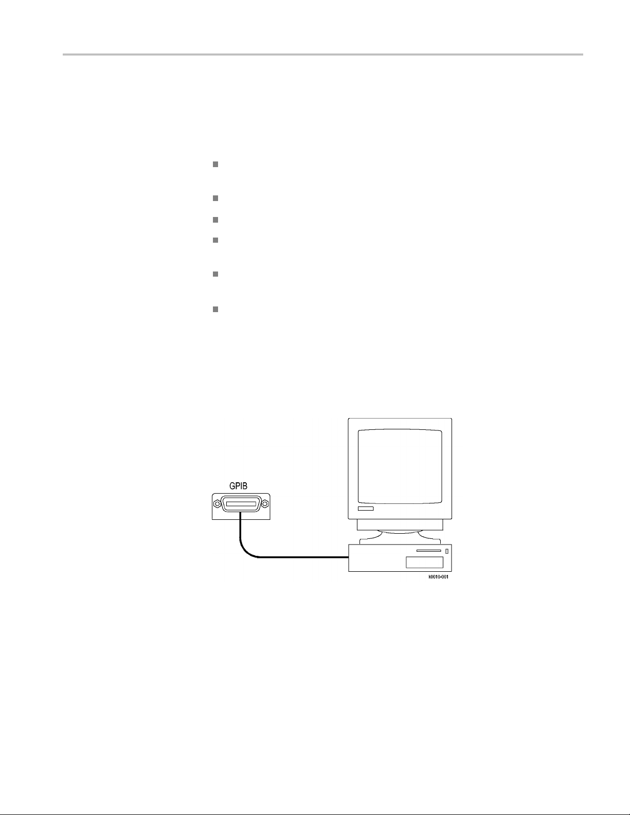
Your instrument has a 24-pin GPIB connector on its rear (side) panel. This
connector has a D-type shell and conforms to IEEE Std 488.1–1987. Attach an
IEEE Std 488.1–1987 GPIB cable to this connector and to your controller as
shown in the following figure.
ments:
share the same device address.
If necessary, the GPIB connectors can be stacked as shown in the figure below.
DSA/CSA/TDS8X00/B Series Programmer Manual 1-3

Getting Started
Setting the GPIB Address
To function correctly, your instrument must have a unique device address. The
default settings for the GPIB configuration are:
GPIB Address: 1
GPIB Mode: GPIB Talk/Listen
1-4 DSA/CSA/TDS8X00/B Series Programmer Manual
Getting Started
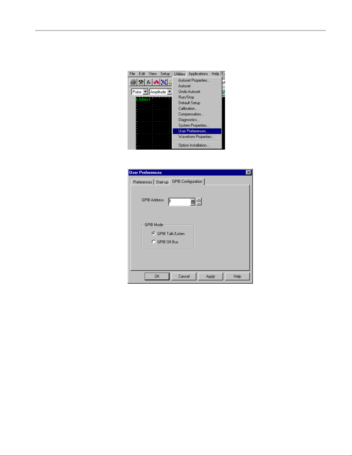
To change eithe
1. Select User Preferences from the Utilities menu.
2. Select the GPIB Configuration Tab.
r of the GPIB settings, do the following:
3. Change the GPIB Address to a unique address.
4. Clic
The instrument is now set up for bidirectional communication with your controller.
ter/Slave Mode
Mas
DSA/CSA/TDS8X00/B Series Programmer Manual 1-5
The DSA8200 is factory set to be a GPIB device (slave), allowing you to control
the instrument via the GPIB port. You can change the instrument to be a GPIB
controller (master), allowing you to control other devices via the GPIB port.
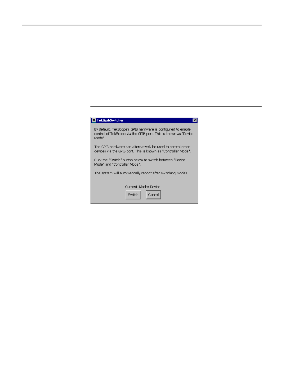
GPIB/VISA Controller/Device (Master/Slave) Switch. The DSA8200 can be
configured as a GPIB Device (Slave) or Controller (Master). The factory setting
is configured to enable control of the instrument via the GPIB port, referred to
as the “Device Mode”.
kOK.
Getting Started
You can change t
port by switching the instrument to be a GPIB Controller referred to as the
“Controller Mode”.
To switch the instrument between these two modes, use the GPIB
Device-Controller Utility found in the Windows Start menu under Programs
> Tektronix DSA8200 > GPIB Device-Controller Utility. Starting this utility
displays the TekGpibSwitcher screen which allows you to switch the instrument
between the two modes.
NOTE. Swit
he instrument to be used to control other devices via the GPIB
ching the mode causes the instrument to automatically re boot.
1-6 DSA/CSA/TDS8X00/B Series Programmer Manual

Command Syntax
You can control the operations and functions of the instrument through the
GPIB interface using commands and queries. The related topics listed below
describe the
conventions that the instrument uses to process them. See the Command Groups
topic in the table of contents for a listing of the commands by command group, or
use the index to locate a specificcommand.
syntax of these commands and queries. The topics also describe the
Backus-Naur Form
Notation
This documentation describes the commands and queries using Backus-Naur
Form (BNF) notation. Refer to the following table for the symbols that are used.
Table 2-1: Symbols for Backus-Naur Form
Symbol Meaning
<>
::=
| Exclusive OR
{ } Group; one element is required
[]
.. .
( ) Comment
Command and Query Structure
mmands consist of set commands and query commands (usually called
Co
commands and queries). Commands modify instrument settings or tell the
instrument to perform a specific action. Queries cause the instrument to return
data and status information.
Defined element
Is defined as
Optional; can be omitted
Previous element(s) may be repeated
Most commands have both a set form and a query form. The query form of the
command differs from the set form by its question m ark on the end. For example,
the set command
commands have both a set and a query form. Some commands have set only and
some have query only.
Messages
DSA/CSA/TDS8X00/B Series Programmer Manual 2-1
A command message is a command or query name followed by any information
the instrument needs to execute the command or query. Command messages may
contain five element types, defined in the following table.
ACQuire:MODe has a query form ACQuire:MODe?.Notall

Command Syntax
Commands
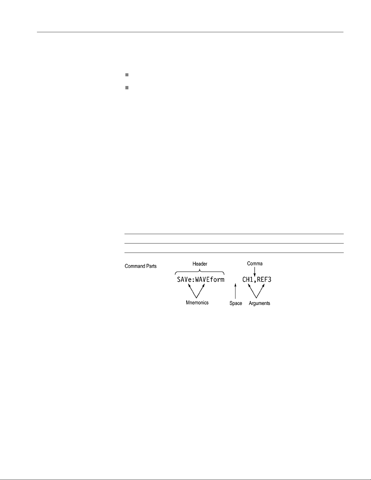
Table 2-2: Comm
Symbol Meaning
<Header>
<Mnemonic>
<Argument
<Comma> A single c
<Space>
Comman
>
ds cause the instrument to perform a specific function or change one of
and Message Elements
This is the basic command name. If the header ends with a question
mark, the command is a query. The header may begin with a colon
(:) c haracte
the beginning colon is required. Never use the beginning colon with
command headers beginning with a star (*).
This is a header subfunction. Some command headers have only one
mnemonic. I
character always separates them from each other.
This is a qu
Some commands have no arguments while others have multiple
arguments. A <space> separates arguments from the header. A
<comma> se
commands. Optionally, there may be white space characters before
and after the comma.
A white space character is used between a command header and the
related argument. Optionally, a white space may consist of multiple
white sp
r. If the command is concatenated with other commands,
f a command header has multiple mnemonics, a colon (:)
antity, quality, restriction, or limit associated with the header.
parates arguments from each other.
omma is used between arguments of multiple-argument
ace characters.
the settings. Commands have the structure:
eader>[<Space><Argument>[<Comma> <Argument>]...]
[:]<H
A command header consists of one or more mnemonics arranged in a hierarchical
ee structure. The first mnemonic is the base or root of the tree and each
or tr
subsequent mnemonic is a level or branch off the previous one. Commands at a
higher level in the tree may affect those at a lower level. The leading colon (:)
always returns you to the base of the command tree.
2-2 DSA/CSA/TDS8X00/B Series Programmer Manual
Command Syntax
Queries
Headers
Queries cause t
he instrument to return status or setting information. Queries
have the structure:
[:]<Header>?
[:]<Header>?[<Space><Argument> [<Coma><Argument>]...]
You can specify a query command at any level within the command tree unless
otherwise noted. These branch queries return information about all the mnemonics
below the sp
ecified branch or level. For example, HIStogram:STATistics:STDdev?
returns the standard deviation of the histogram, while HIStogram:STATistics?
returns all the histogram statistics, and HIStogram? returns all the histogram
parameters.
You can control whether the instrument returns headers as part of the query
response. Use the HEADer command to control this feature. If header is on,
the query response returns command headers, then formats itself as a valid set
command. When header is off, the response includes only the values. This may
make it easier to parse and extract the information from the response. The table
shows the difference in responses.
below
Table 2-3: Comparison of Header Off and Header On Responses
Query Header Off Header On
TIME?
ACQuire:NUMAVg?
"14:30:00" :TIME"14:30:00"
100
:ACQUIRE:NUMAVG 100
Clearing the Instrument
You can clear the Output Queue and reset the instrument to accept a new
command or query by using the selected Device Clear (DCL) GPIB function.
Refer to your GPIB library documentation for further d etails about the selected
Device Clear operation.
DSA/CSA/TDS8X00/B Series Programmer Manual 2-3

Command Syntax
Command Entry
The following rules apply when entering commands:
You can enter commands in upper or lower case.
You can precede any command with white space characters. White space
characters include any combination of the ASCII control characters 00 through
09 and 0B through 20 hexadecimal (0 through 9 and 11 through 32 decimal).
The instrument ignores commands consisting of any combination of white
space characters and line feeds.
Abbreviating
atenating
Conc
You can abbreviate many instrument commands. Each command in this
documentation shows the abbreviations in capitals. For example, you can enter
the command ACQuire:NUMAvg simply as ACQ:NUMA or acq:numa.
Abbreviation rules may change over time as new instrument models are
introduced. Thus, for the most robust code, use the full spelling.
If you use the HEADer command to have command headers included as part
of query responses, you can further control whether the returned headers are
abbreviated or are full-length with the VERBose command.
You can concatenate any combination of set commands and queries using a
semicolon (;). The instrument executes concatenated commands in the order
received.
2-4 DSA/CSA/TDS8X00/B Series Programmer Manual

Command Syntax
When concatena
ting commands and queries, you must follow these rules:
1. Separate completely different headers by a semicolon and by the beginning
colon on all commands except the first one. For example, the commands
TRIGger:MODe NORMal and ACQ uire:NUMAVg 10, can be concatenated
into the following single command:
TRIGger:MODe NORMal;:ACQuire:NUMAVg 10
2. If concatenated commands have headers that differ by only the last mnemonic,
you can abbreviate the second command and eliminate the beginning colon.
For example, you can concatenate the commands
ACQuire:MODe ENVelope
and ACQuire:NUMAVg 10 into a single command:
ACQuire:MODe ENVelope; NUMAVg 10
The longer version works equally well:
ACQuire:MODe ENVelope;:ACQuire:NUMAVg 10
3. Never precede a star (*) command with a colon:
ACQuire:MODe ENVelope;*OPC
Any commands that follow will be processed as if the star command was not
there so the commands,
ACQuire:MODe ENVelope;*OPC;NUMAVg 10 will
set the acquisition mode to envelope and set the number of acquisitions for
averaging to 10.
4. When you concatenate queries, the responses to all the queries are
concatenated into a single response message. For example, if the display
imageview color is temperature and the display recordview color is spectral,
the concatenated query
RECORDVIEW?
will return the following.
DISplay:COLOr:PALETTE:IMAGEVIEW?;
If the header is on:
:DISPLAY:COLOR:PALETTE:IMAGEVIEW TEMPERATURE;
:DISPLAY:COLOR:PALETTE:RECORDVIEW SPECTRAL
If the header is off:
TEMPERATURE;SPECTRAL
5. Set commands and queries may be concatenated in the same message. For
example,
ACQuire:MODe SAMple;NUMAVg?;STATE?
is a valid message that sets the acquisition mode to sample. The message then
queries the number of acquisitions for averaging and the acquisition state.
Concatenated commands and queries are executed in the order received.
Here are some invalid concatenations:
DISplay:STYle:NORMal;ACQuire:NUMAVg 10 (no colon before ACQuire)
DSA/CSA/TDS8X00/B Series Programmer Manual 2-5

Command Syntax
Terminating
DISplay:COLor
DISplay:COLor:CURSor1 1;CURSor2 5 instead)
DISplay:STYl
DISplay:COLor:CURSor1 1;COLor:CURSor2 5 (levels o f the mnemonics
are differe
front of
nt; either remove the second use of
COLor:CURSor2 5)
:CURSor1 1;:CURSor2 5
e:NORMal;:*OPC
(colon before a star (*) command)
(extra colon before CURSor2; use
COLor or place :DISplay: in
This documentation uses <EOM> (End of message) to represent a message
terminato
r.
Table 2-4: End of Message Terminator
Symbol Meaning
<EOM>
Message terminator
The end-of-message terminator must be the END message (EOI asserted
concurrently with the last data byte). The last data byte may be an ASCII linefeed
(LF) ch
aracter.
This instrument does not support ASCII LF only message termination. The
ument always terminates outgoing messages with LF and EOI.
instr
Constructed Mnemonics
Some
a channel mnemonic can be CH1, CH2, CH3, ... through CH8. You use these
mnemonics in the command just as you do any other mnemonic. For example,
there is a CH1:POSition command, and there is also a CH2:POSition command.
In the command descriptions, this list of choices is abbreviated a s CH<x>.
Cursor Position
Mnemonics
When cursors are displayed, commands may specify which cursor of the pair to
use.
Table 2-5: Cursor Mnemonics
Symbol Meaning
CURSOR<x>
POSITION<x>
HPOS<x>
header mnemonics specify one of a range of mnemonics. For example,
A cursor selector; <x> is either 1 or 2.
A cursor selector; <x> is either 1 or 2.
A cursor selector; <x> is either 1 or 2.
2-6 DSA/CSA/TDS8X00/B Series Programmer Manual

Command Syntax
Histogram Statistics
Specifier Mnemonics
Magnified Timebase
Specifier Mnemonics
Mask Specifier Mnemonics
Commands can sp
ecify which Sigma value to return for histogram statistics as a
mnemonic in the header. A Sigma is specified in this way:
Table 2-6: Histogram Statistics Specifier Mnemonics
Symbol Meaning
SIGMA<x> A histogram statistics specifier; <x> is either 1, 2, or 3.
Commands can specify which of two magnified timebases to set or query as a
mnemonic in the header. The magnified timebases are specified in this way:
Table 2-7: Magnified Timebase Specifier Mnemonics
Symbol Meaning
MAG<x> A magnified specifier; <x> is 1or 2.
Commands can specify w hich mask to set or query as a mnemonic in the header.
The masks are specified in this way:
Table2-8: MaskSpecifier Mnemonics
Measurement Specifier
Mnemonics
Channel Mnemonics
Symbol Meaning
MASK<x> A mask specifier; <x> is 1 through 8.
Commands can specify which measurement to set or query as a mnemonic in
the header. Up to eight automated measurements may be displayed with each
displayed waveform. The displayed measurements are specified in this way:
Table 2-9: Measurement Specifier Mnemonics
Symbol Meaning
MEAS<x> A measurement specifier; <x> is 1 through 8.
SOURCE<x> A waveform specifier; <x> is either 1 (Source 1 waveform) or 2 (Source
2 waveform).
REFLevel<x>
A waveform specifier for reference level measurements; <x> is either 1
(Source 1 waveform) or 2 (Source 2 waveform).
Commands specify the channel to use as a mnemonic in the header.
Table 2-10: Channel Mnemonics
Symbol Meaning
CH<x> A channel specifier; <x> is 1 through 8.
DSA/CSA/TDS8X00/B Series Programmer Manual 2-7

Command Syntax
Math Waveform
Mnemonics
Reference Waveform
Mnemonics
Waveform Database
Mnemonics
Commands can sp
ecify the mathematical waveform to use as a mnemonic in
the header.
Table 2-11: Math Waveform Mnemonics
Symbol Meaning
Math<x>
ands can specify the reference waveform to use as a mnemonic in the
Comm
A math waveform specifier; <x> is 1 through 8.
header.
Table 2-12: Reference Waveform Mnemonics
Symbol Meaning
REF<x>
A reference waveform specifier; <x> is 1 through 8.
Commands can specify the reference waveform to use as a mnemonic in the
header.
Table 2-13: Waveform Database Mnemonics
Rules
Abbreviating
Symbol Meaning
WFMDB<x>
A waveform database specifier; <x> is either 1 or2.
The following rules apply when entering commands:
You can enter commands in upper or lower case.
You can precede any command with white space characters. White space
characters inc
lude any combination of the ASCII control characters 00 through
09 and 0B through 20 hexadecimal (0 through 9 and 11 through 32 decimal).
The instrument ignores commands consisting of any combination of white
space characters and line feeds.
You can abbreviate many instrument commands. Each command in this
documentation shows the abbreviations in capitals. For example, you can ent
the command ACQuire:NUMAvg simply as ACQ:NUMA or acq:numa.
Abbreviation rules may change over time as new instrument models are
introduced. Thus, for the most robust code, use the full spelling.
If you use the HEADer command to have command headers included as part
of query responses, you can further control whether the returned headers are
abbreviated or are full-length with the VERBose command.
er
2-8 DSA/CSA/TDS8X00/B Series Programmer Manual

Argument Types
Command Syntax
Numeric
Quoted String
Many instrument commands require numeric arguments. The syntax shows the
format that the instrument returns in response to a query. This is also the preferred
format when sending the command to the instrument though any of the formats
will be accepted. This documentation represents these arguments as follows:
Table 2-14: Numeric Arguments
Symbol Meaning
<NR1>
<NR2> Floating point value without an exponent
<NR3> Floating point value with an exponent
Signed integer value
Most numeric arguments will be automatically forced to a valid setting, either by
rounding or truncating, when an invalid number is input unless otherwise noted
in the command description.
Some commands accept or return data in the form of a quoted string, which is
simply a group of ASCII characters enclosed by a single quote (') or double quote
("). The following i
string"
. This documentation represents these arguments as follows:
s an example of a quoted string:
"This is a quoted
Table 2-15: Quoted String Argument
Symbol Meaning
<QString> Quoted string of ASCII text
A quoted string can include any character defined in the 7-bit ASCII character
set. Follow these rules when you use quoted strings:
1. Use the same type of quote character to open and close the string. For
example:
"this is a valid string".
2. You can mix quotation marks within a string as long as you follow the
previous rule. For example,
"this is an 'acceptable' string".
3. You can include a quote character within a string by repeating the quote. For
example:
"here is a "" mark".
4. Strings can have upper or lower case characters.
5. If you use a GPIB network, you cannot terminate a quoted string with the
END message before the closing delimiter.
6. A carriage return or line feed embedded in a quoted string does not terminate
the string, but is treated as just another character in the string.
7. The maximum length of a quoted string returned from a query is 1000
characters.
DSA/CSA/TDS8X00/B Series Programmer Manual 2-9
Command Syntax
Block
Here are some in
"Invalid string argument' (quotes are not of the same type)
"test<EOI>" (termination character is embedded in the string)
valid strings:
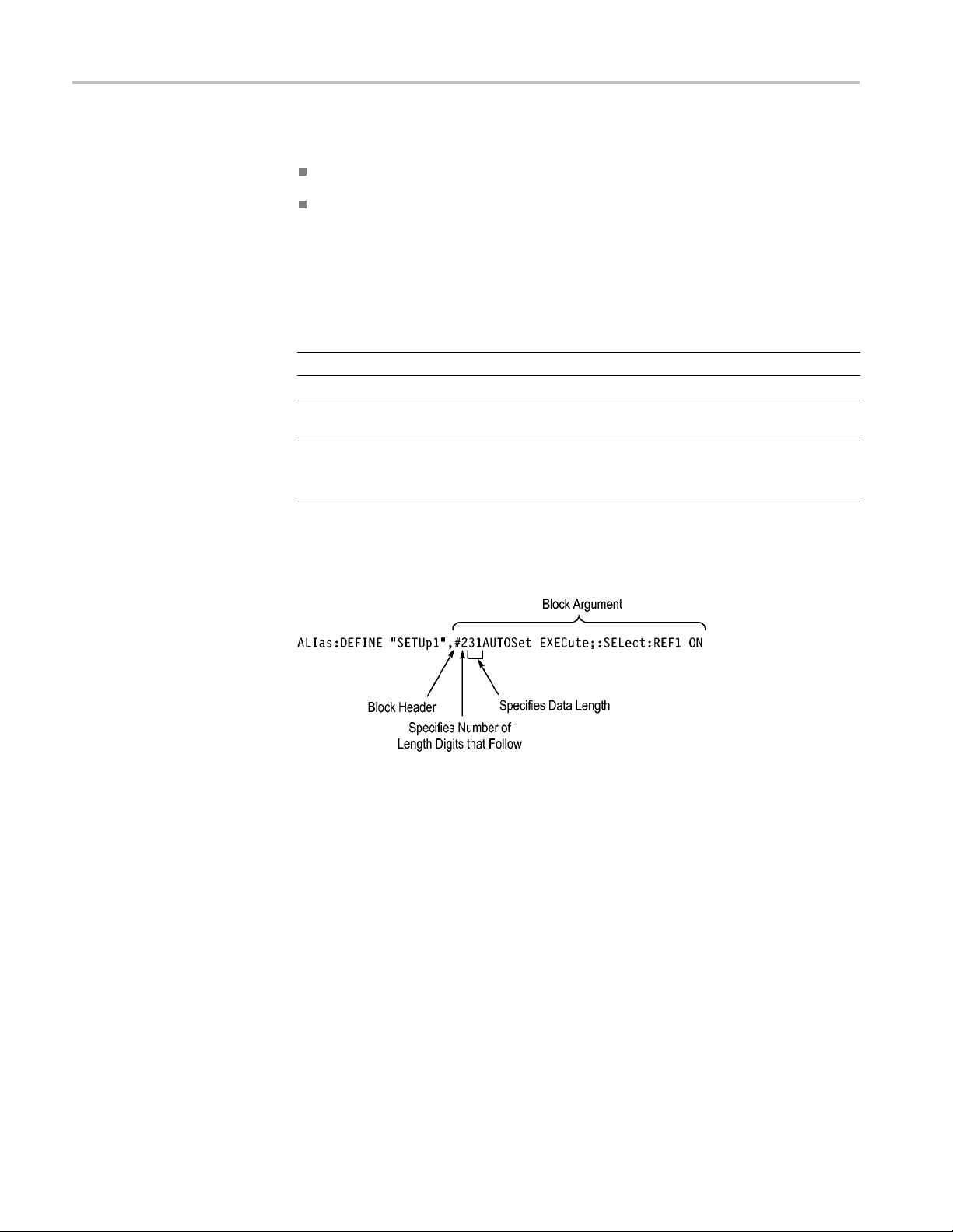
Several instrument commands use a block argument form (see the following table).
Table 2-16: Block Argument
Symbol Meaning
<NZDig>
<Dig>
<DChar> A character with the hexadecimal equivalent of 00 through FF (0
<Block>
<NZDig
> specifies the number of <Dig> elements that follow. Taken together,
A nonzero digit character in the range of 1–9
A digit character, in the range of 0–9
through 255 decimal)
A block of data bytes defined as: <Block> ::=
{#<NZDig><Dig>[<Dig>...][<DChar>...]
|#0[<DChar>...]<terminator>}
the <NZDig> and <Dig> elements form a decimal integer that specifies how
many <DChar> elements follow.
Command Entry
Concatenating
2-10 DSA/CSA/TDS8X00/B Series Programmer Manual
You can concatenate any combination of set commands and queries using a
emicolon (;). The instrument executes concatenated commands in the order
s
received.

Command Syntax
When concatena
ting commands and queries, you must follow these rules:
Separate completely different headers by a semicolon and by the beginning
colon on all commands except the first one. For example, the commands,
TRIGger:MODe NORMal and ACQ uire:NUMAVg 10, can be concatenated
into the following single command:
TRIGger:MODe NORMal;:ACQuire:NUMAVg 10
If concatenated commands have headers that differ by only the last mnemonic,
you can abbreviate the second command and eliminate the beginning colon.
For example, you can concatenate the commands ACQuire:MODe ENVelope
and ACQuire:NUMAVg 10 into a single command:
ACQuire:MODe ENVElope; NUMAVg 10
The longer version works equally well:
ACQuire:MODe ENVElope;:ACQuire:NUMAVg 10
Never precede a star (*) command with a colon:
ACQuire:MODe ENVElope;*OPC
Any commands that follow will be processed as if the star command was
not there. For example, the ACQuire:MODe ENVElope;*OPC;NUMAVg
10 commands will set the acquisition mode to envelope and set the number
of acquisitions for averaging t
o 10.
When you concatenate queries, the responses to all the queries are
concatenated into a single response message. For example, if the display
background color is white and the display foreground color is black, the
concatenated query DISplay:COLor:BACKGround?;FOREGround? will
return the following:
Iftheheaderison:
:DISPLAY:COLOR:BACKGROUND 7;
:DISPLAY:COLOR:FOREGROUND 0
If the header is off:
7;0
Set commands and queries may be concatenated in the same message. For
example,
ACQuire:MODe SAMple;NUMAVg?;STATE?
is a valid message that sets the acquisition mode to sample. The message
then queries the number of acquisitions for averaging and the acquisition
state. Concatenated commands and queries are executed in the order
received.
Here are some invalid concatenations:
DSA/CSA/TDS8X00/B Series Programmer Manual 2 -11

Command Syntax
Terminating
DISplay:STYle
:NORMal;ACQuire:NUMAVg 10 (no colon before ACQuire)
DISplay:COLor:CURSor1 1;:CURSor2 5 (extra colon before CURSor2; use
DISplay:COLo
r:CURSor11;CURSor25instead)
DISplay:STYle:NORMal;:*OPC (colon before a star (*) command)
ISPlay:COLor:CURSor1 1;COLor:CURSor2 5 (levels of the mnemonics
are different; either remove the second use of COLor or place :DISplay: in
front of COL
or:CURSor2 5)
This documentation uses <EOM> (End of message) to represent a message
terminator.
Table 2-
Symbol Meaning
<EOM>
17: End of Message Terminator
Message
terminator
The end-of-message terminator must be the END message (EOI asserted
concurrently with the last data byte). The last data byte may be an ASCII linefeed
(LF) character. This instrument doe s not support ASCII LF only message
nation. The instrument always terminates outgoing messages with LF and
termi
EOI. It allows white space before the terminator. For example, it allows CR LF.
2-12 DSA/CSA/TDS8X00/B Series Programmer Manual

Command Groups
The DSA8200 programmable interface conforms to Tektronix standard codes
and formats except where noted. The GPIB interface also conforms to IEEE
Std 488.2-19
Acquisition Command Group
Use the commands in the Acquisition Command Group to set up the modes and
functions that control how the instrument acquires the signals you input to the
channels and processes them into waveforms.
Using these commands for acquiring waveforms, you can do the following:
Start and stop acquisitions.
Control whether each waveform is simply acquired, averaged, or enveloped
over successive acquisitions of that waveform.
Set the controls or conditions that start and stop acquisitions.
Determine the action the system takes upon completing an acquisition, such
as saving all waveforms and taking a me
stopped.
87 except where noted.
asurement when the acquisition is
Get data on acquired waveforms, histograms, and masks.
Get acquisition parameters.
Clear all acquired data.
Table 2-18: Acquisition Commands
Command Description
ACQuire?
ACQuire:CURRentcount:ACQWfms? Returns acquired waveforms count
ACQuire:CURRentcount:HISTHits?
ACQuire:CURRentcount:HISTWfms? Returns histogram waveforms count
ACQuire:CURRentcount:MASKHits<x>?
ACQuire:CURRentcount:MASKSamples?
ACQuire:CURRentcount:MASKTHits?
ACQuire:CURRentcount:MASKWfms? Returns mask waveforms count
ACQuire:DATA:CLEar Clears all acquired data
ACQuire:MODe Sets or returns acquisition mode
ACQuire:NUMAVg Sets or returns number of acquisitions for an
ACQuire:SAVEFile:SAVEScreen Sets or returns the file to save screen to on
Returns acquisition parameters
Returns histogram hits count
Returns mask hits count
Returns mask samples count
Returns total mask hits count
averaged waveform
acquisition stopped
DSA/CSA/TDS8X00/B Series Programmer Manual 2-13

Command Groups
Table 2-18: Acquisition Commands (cont.)
Command Description
ACQuire:SAVEFile:SAVEWfm Sets or returns the file to save waveform
data to on acquisition stopped
ACQuire:STATE Starts, stops, or returns acquisition state
ACQuire:STOPAfter? Returns all stopafter parameters
ACQuire:STOPAfter:ACTion Sets or returns the stopafter action
ACQuire:STOPAfter:BELL Sets or returns whether to sound bell on
acquisition stopped
ACQuire:STOPAfter:CONDition Sets or r eturns the acquisition stopafter
condition
ACQuire:STOPAfter:COUNt Sets or returns the stopafter count value
The stopafter count value is
dependent on the condition set by the
ACQuire:STOPAfter:CONDiton command
ACQuire:STOPAfter:MODe Sets or returns the stopafter mode
Calibration Command Group
The calibration commands provide information about the current state of the
calibration for the mainframe and all resident sampling-module channels.
Additional commands allow you to update portions of the “electronic calibration
sticker” information, to check the protection status of the calibration information,
and to set or query the front-panel DC calibration output.
Command
CALibrate:DATE:CH<x>? Returns date and time of the last sampling
CALibrate:DATE:MAInframe? Returns the date and time of the last
CALibrate:DCCALibrator Sets or returns the value of the DC Calibrator
CALibrate:HOSTinfo:CH<x>? Returns the mainframe model number, serial
CALibrate:LOCK:STATus? Returns the status of the calibration
CALibrate:STATus:CH<x>? Returns calibration status for specified
CALibrate:STATus:MAInframe? Returns calibration status for mainframe
Description
module channel<x> calibration
mainframe calibration
voltage
number, and mainframe channel<x> in which
the sampling module channel was located
during the last calibration information update.
protection mode.
sampling module channel<x>
2-14 DSA/CSA/TDS8X00/B Series Programmer Manual

Command Groups
Command
CALibrate:TEMPerature:CH<x>? Returns the difference in ºC between
CALibrate:TEMPerature:MAInframe? Returns the difference in ºC between the
CALibrate:UPDATEinfo:ALL Updates date, time, temp and (for sampling
CALibrate:UPDATEinfo:CH<x> Updates the calibration information in the
CALibrate:UPDATEinfo:MAInframe Updates the calibration information in the
Compensation Command Group
The compensation commands provide information about the current state of
the compensation for the mainframe and all resident module channels, means
to invoke compensation functions, and management of compensation storage
memory locations.
Description
the current sampling module c hannel<x>
temperature a
at the last calibration information update
current mainframe temperature and the
temperatur
information update
modules) host mainframe information
nonvolat
channel<x>
nonvolatile memory of the mainframe
nd the temperature recorded
e recorded at the last calibration
ile memory of the sampling module
There are two nonvolatile compensation storage memory blocks in the mainframe
and each sampling module channel: Factory and User. In addition, there
is a volatile run-time, in-use version of all compensation data, which is the
compensation data actually used during the operation of the instrument.
Command
COMPensate:ALL Compensates the mainframe and all resident
COMPensate:CH<x> Compensates the module channel<x> for
COMPensate:DARKLev:CH<x> Compensates the specified optical
COMPensate:DATE:CH<x>? Returns date and time of the current
COMPensate:DATE:MAInframe? Returns date and time of the current in-use
COMPensate:MAInframe Compensates the mainframe for DC
COMPensate:OPTGAIN:CH<x> Compensates optical user wavelength gain
Description
modules
DC variances
channel<x> by removing residual DC offsets
in the entire vertical path
in-use compensation data for the module
channel<x>
compensation data for the mainframe
variances
(wavelengths and input power)
DSA/CSA/TDS8X00/B Series Programmer Manual 2-15

Command Groups
Command
COMPensate:RECAll:FACTory:ALL Recalls compensation data for the mainframe
COMPensate:RECAll:FACTory:CH<x> Recalls compensation data from the
COMPensate:RECAll:FACTory:MAInframe Recalls compensation data from the
COMPensa
COMPens
COMPen
COMPensate:RESults? Returns brief explanation of the results of the
COMP
COMPensate:SAVe:USER:ALL Saves volatile run-time compensation
COMPensate:SAVe:USER:CH<x> Saves volatile run-time compensation data
COMPensate:SAVe:USER:MAInframe Saves volatile run-time compensation data
COMPensate:STATus:CH<x>? Returns the current compensation status of
COMPensate:STATus:MAInframe? Returns the current compensation status of
te:RECAll:USER:ALL
ate:RECAll:USER:CH<x>
sate:RECAll:USER:MAInframe
ensate:RESults:VERBose?
Description
and all resident module channels from their
nonvolatile f
compensation memory
nonvolatile factory memory of the module
channel<x>
memory
nonvolatile factory memory in the mainframe
into its as
Recalls c
and all resident module channels from their
respective nonvolatile user memories into
run-time
Recalls
nonvolatile user memory of the module
channel<x> into its associated run-time
memory
Recall
nonvolatile user memory in the mainframe
into its associated run-time mem o ry
last c
Retu
with a more detailed explanation than the
COMPensate:RESults? query returns
a for the mainframe and all resident
dat
modules into their associated nonvolatile
user memories
r the module channel<x> into its nonvolatile
fo
user memory
for the mainframe into its nonvolatile user
emory
m
the specified module channel<x>
the mainframe
actory memories into run-time
into its associated run-time
sociated run-time memory
ompensation data for the mainframe
compensation memory
compensation data from the
s compensation data from the
ompensation
rns results of last compensation,
2-16 DSA/CSA/TDS8X00/B Series Programmer Manual

Command Groups
Command
COMPensate:TEMPerature:CH<x>? Returns the difference in ºC between
COMPensate:TEMPerature:MAInframe? Returns the difference in ºC between the
Cursor Command Group
Use the commands in the Cursor Command Group to control the cursor display
and readout. You can use these commands to control the setups for cursor 1 and
cursor 2, such as waveform source, cursor position, and cursor color.
You can also use the commands to select one of the following cursor functions:
Description
the current temperature of the module
channel<x> an
residing in its in-use run-time compensation
memory
current mai
temperature currently residing in its in-use
run-time compensation memory
d the temperature currently
nframe temperature and the
Off Shuts off the display of all cursors.
Vertical Bars. Displays vertical bar cursors, which provide traditional
horizontal unit readouts for Cursor 1 (bar1), Cursor 2 (bar2), the delta between
them, and 1/delta (results in frequency when the horizontal unit is time).
Horizontal Bars. Displays horizontal bar cursors, which provide traditional
vertical unit readouts for Cursor 1 (bar1), Cursor 2 (bar2), and the delta
between them.
Wavef orm. Displays waveform cursors, which provide horizontal and
vertical unit readouts for Cursor 1 (bar1), Cursor 2 (bar2), the delta between
them, and 1/delta (results in frequency when the horizontal unit is time).
Command
CURSor?
CURSor:CURSor<x>:COLOR Sets or returns cursor<x> color
CURSor:CURSor<x>:SOUrce Sets or returns cursor<x> waveform source
CURSor:FUNCtion Sets or returns the cursor type
CURSor:HBArs?
CURSor:HBArs:DELTa? Returns hbars cursors vertical difference
CURSor:HBArs:POSition<x> Sets or returns the hbar cursor<x> vertical
CURSor:SELect Sets or returns which cursor is active for
CURSor:VBArs?
CURSor:VBArs:DELTa? Returns the difference between vbar cursors
Description
Returns all cursor parameters
and timebase
Returns hbar cursor parameters
position
front-panel control
Returns vbar cursor parameters
DSA/CSA/TDS8X00/B Series Programmer Manual 2-17

Command Groups
Display Contro
Command
CURSor:VBArs:POSition<x> Sets or r eturns the vbar cursor<x> horizontal
CURSor:WAVeform? Returns waveform cursor parameters
CURSor:WAVeform:HDELTa? Returns the horizontal difference between
CURSor:WAV
CURSor:WA
CURSor:WAVeform:VDELTa? Returns the vertical difference between
eform:HPOS<x>?
Veform:POSition<x>
l Command Group
You use the commands in the Display Control Command Group to change the
graticule style, the displayed intensities, and to set the characteristics of the
waveform disp
You can set the following:
Background color (default is black) and foreground color (default is silver).
lay.
Description
position
waveform cu
Returns the
Sets or ret
cursor <x>
waveform cursors
rsors
position of waveform cursor <x>
urns the position of waveform
Cursor, histogram, mask, and measurement annotation colors.
Whether cursor, histogram, mask, and measureme nt readouts are displayed.
Whether measurement annotations are displayed.
Whether waveforms are simply displayed in Normal mode as dots or vectors,
in Variable Persistence mode, or in Infinite Persistence mode.
Whether the instrument uses interpolation to increase sample density of
waveform for record lengths less than 500 points, and, if interpolation is
used, which type (Sin(x) or Linear).
The style of graticule that underlies the waveforms.
Use the commands to set the style that best displays your waveforms and
graticule display properties. The mode you choose globally affects all displayed
waveforms; fo
r example, you cannot set channel 1 to display in Normal mode and
channel 2 in Variable Persistence mode.
There are four graticule settings:
Frame
Grid
Cross Hair
Full
2-18 DSA/CSA/TDS8X00/B Series Programmer Manual

Command Groups
Choose Frame or
Grid for minimum clutter on screen; choose Full or Cross Hair
for ease in taking graticule measurements.
Command
DISplay?
DISplay:COLor?
DISplay:COLor:BACKground Sets or returns graticule background color
DISplay:COLor:CURSor<x> Sets or returns cursor<x> color
DISplay:COLor:FOREground Sets or returns graticule foreground color
DISplay:COLor:HIStogram Sets or returns histogram rectangle and plot
DISplay:COLor:MASK Sets or returns mask color
DISplay:CURSReadout Sets or returns the display state of the cursor
DISplay:DATe Turns the Date/Time display on or off or
DISplay:GRAticule?
DISplay:GRAticule:HDIVS? Returns the number of horizontal divisions
DISplay:GRAticule:STYLE Sets or returns the graticule style
DISplay:GRAticule:VDIVS? Returns the number of vertical divisions in
DISplay:HISTReadout Sets or returns the display state of the
DISplay:INTERPolat Sets or returns the display interpolation type
DISplay:MASKReadout Sets or returns the display state of the mask
DISplay:MEASBar Sets or returns the display state of the
DISplay:MEASReadout Sets or returns the display state of the
DISplay:PERSistence Sets or returns the display persistence time
DISplay:SHOWVector Sets or returns the show vector status
DISplay:STYle Sets or returns the display persistence style
DISplay:WFMReadout Sets or returns the display state of the
Description
Returns current display settings
Returns color group settings
color
readout
returns the status of the Date/Time display
Returns all graticule parameters
in graticule
graticule
histogram readout
readout
measurement bar
measurement readout
waveform readout
Hard Copy Command Group
Hard copy commands allow you to make hard copies of your data file or send
hard copy data in various formats to a specified file.
DSA/CSA/TDS8X00/B Series Programmer Manual 2-19

Command Groups
Histogra
Command
HARDCopy Sends a screen copy to the selected port or
HARDCopy:FILEName Sets or returns the hard copy file path
HARDCopy:FORMat Selects the file format when sending
HARDCopy:INKSaver Sets the Ink-saver mode on or off. Ink-saver
m Command Group
Histogram commands let you select the type of histogram, what part of the
waveform should go into the histogram , and histogram statistics. You can use
comman
Select any channe l, math, or reference waveform and create a histogram of
vertic
Adjust the limits of the box that d efine the area on the waveform from which
the hi
waveform coordinates or percentage-of-display coordinates.
Description
returns the selected port and file path
a hardcopy t
HARDCopy:FILEName command
mode can conserve ink and improve print
quality wh
displays
oafile using the
en printing images of waveform
ds from this group to do the following:
al or horizontal values for it.
stogram data is obtained. The histogram box can be set using source
te a linear or logarithmic plot of histogram data and set plot size and color.
Crea
Clear histogram count and restart.
Turn the display of the histogram on or off.
Enable or disable histogram calculations.
Get histogram statistics, such as total hits, mean value, peak-to-peak value,
and standard deviation.
Get all the histogram parameters.
NOTE. You can also export a histogram to a file of comma-separated values. See
the EXPort command for more information.
Command
HIStogram?
HIStogram:BOX Sets or returns the left, top, right, and bottom
Description
Return all histogram parameters
positions of the histogram box, in source
waveform coordinates
2-20 DSA/CSA/TDS8X00/B Series Programmer Manual

Command Groups
Command
HIStogram:BOXPcnt Sets or returns same as HIStogram:BOX, but
HIStogram:C
HIStogram:
HIStogram:DISplay Sets or returns whether histogram data is
HIStogram:ENABle
HIStogra
HIStogram:SIZe Sets or returns the width (or height) of the
HIStog
HIStogram:STATistics?
HIStogram:STATistics:HITS?
HIStogram:STATistics:MEAN?
HIStogram:STATistics:MEDIAN?
HIStogram:STATistics:PEAKHits?
HIStogram:STATistics:PKTOPK?
HIStogram:STATistics:SIGMA<x>? Returns population density for ±<x> sigma
IStogram:STATistics:STDdev?
H
HIStogram:STATistics:WAVeforms? Returns the number of waveforms used in
HIStogram:TYPE Sets or returns whether the histogram is
HIStogram:WFMDB:STATE Sets or returns whether the histogram
OLOr
COUNt
m:MODe
ram:SOUrce
Description
in percentage coordinates, with 0,0 upper left
and 100,100 lo
Sets or retur
Clears hist
restarts counting
displayed on screen
Enables or disables histogram calculations
Returns whether histogram calculations are
enabled
Sets type
vertical or horizontal
Returns the type of histogram
ram on the screen in divisions
histog
Sets or
and timebase (Main, Mag1, or Mag2) for
histogram
Returns all histogram statistics
Returns the histogram total hits value
Returns the histogram mean value
Returns the histogram median value
Returns the histogram peak hits value
Returns the histogram peak to peak value
alue
v
Returns the histogram standard deviation
alue
v
histogram
displayed linearly or logarithmically
counting is on a waveform database
wer right
ns the histogram color
ogram count source data and
of histogram to be done, either
returns the source waveform
Horizontal Command Group
You use the commands from the Horizontal Command Group to control the
timebases of the instrument. You can use these commands to do the following:
DSA/CSA/TDS8X00/B Series Programmer Manual 2-21

Command Groups
Set the scale (t
ime per division) of the Main, Mag1, and Mag2 timebases.
Set the record lengths for the Main, Mag1, and Mag2 timebases.
Get the time of first point and time of last point for the Main, Mag1, and
Mag2 timebases.
Get the sample resolution of the Ma in, Mag1, and Mag2 timebases.
Set the horizontal position for the Main, Mag1, and Mag2 timebases.
Set the horizontal reference for the Main, Mag1, and Mag2 timebases.
Enable or disable the acquisition and display of the Mag1 and Mag2 timebases.
Set the timebase mode.
Set timebase units to seconds, bits, or distance.
Set the Dielectric constant and propagation velocity.
Select a communication standard, such as OC12, that automatically sets the
associated bit rate.
Adjust the external 10 MHz reference frequency to ensure that the timebase
locks.
Set the parameters for FrameScan mode, and turn the mode on or of
f.
Get the screen resolution of the Main, Mag1, and Mag2 timebases.
Get all the horizontal settings.
Command
AUTOSet:HORizontal Sets or returns the status for the horizontal
HORizontal?
HORizontal:BITS:BITRate Sets or returns the bit rate of the timebase
HORizontal:BITS:STANdard Sets or returns the communication standard
HORizontal:DISTance:DIELectric Sets or returns the dielectric constant
HORizontal:DISTance:PVELocity Sets or returns the propagation velocity
HORizontal:EXT10MHZref:FREQ Sets or returns the external horizontal
HORizontal:FRAMescan:AUTOPosition Sets or returns the adjustment for timing
HORizontal:FRAMescan:RESET Resets FrameScan acquisition
HORizontal:FRAMescan:SCANBits Sets or returns the number of bits in frame to
HORizontal:FRAMescan:STARTBit Sets or returns the bit number of first bit
Description
Autoset options
Returns all horizontal settings
(or NO Ne) for the bit r ate
reference
skew between data input and trigger input in
FrameScan acquisition mode
scan in FrameScan acquisition mode
scanned in FrameScan acquisition mode
2-22 DSA/CSA/TDS8X00/B Series Programmer Manual

Command Groups
Command
HORizontal:FRAMescan:STATE Sets or returns the FrameScan acquisition
HORizontal:MAGnify<x>?
HORizontal:MAGnify<x>:POSition Sets or returns the horizontal position for
HORizontal
HORizontal:MAGnify<x>:REFPoint Sets or returns the Mag<x> timebase
HORizontal:MAGnify<x>:RESolution?
HORizontal:MAGnify<x>:SCAle Sets or returns the Mag<x> timebase time
HORizon
HORizontal:MAGnify<x>:TOLPoint? Returns the Mag<x> timebase time of last
HORizontal:MAGnify<x>:VIEW Sets or returns the Mag<x> timebase view
HORi
HORizontal:MAIn:POSition Sets or returns the horizontal position for the
HORizontal:MAIn:RECordlength Sets or returns the main timebase record
HO
HORizontal:MAIn:RESolution?
HORizontal:MAIn:SCAle Sets or returns the m ain timebase time per
HORizontal:MAIn:TOFPoint? Returns the main timebase time of first point
HORizontal:MAIn:TOLPoint? Returns the main timebase time of last point
HORizontal:MATH<x>:MAGnify<x>:
POSition?
HORizontal:MATH<x>:MAGnify<x>:
RECordlength?
HORizontal:MATH<x>:MAGnify<x>:
RESolution?
HORizontal:MATH<x>:MAGnify<x>:SCAle?
HORizontal:MATH<x>:MAGnify<x>:
TOFPoint?
:MAGnify<x>:RECordlength
tal:MAGnify<x>:TOFPoint?
zontal:MAIn?
Rizontal:MAIn:REFPoint
Description
mode on or off
Returns all Mag<x> timebase settings
Mag<x> time
Sets or retu
length
reference point in percent
Returns the Mag<x> timebase acquisition
resolution
per divi
Returns
point
point
on or o
rns the time per division of the main
Retu
time base
main timebase
ngth
le
ts or returns the main timebase reference
Se
position in percent of record
eturns the main timebase acquisition
R
resolution
division
Returns the Math<x>"Acquisition" horizontal
position for Mag<x> timebase
Returns the Math<x> Mag<x> timebase
record length
Returns the Math<x> Mag<x> timebase
acquisition resolution
Returns the Math<x> Mag<x> timebase time
per division
Returns the Math<x> Mag<x> timebase time
of first point
base
rns the Mag<x> timebase record
sion
the M ag<x> timebase time of first
ff
DSA/CSA/TDS8X00/B Series Programmer Manual 2-23

Command Groups
Command
HORizontal:MATH<x>:MAGnify<x>:
TOLPoint?
HORizontal:MATH<x>:MAIn:POSition? Returns the Math<x> horizontal position for
HORizontal
HORizontal
HORizonta
HORizont
HORizont
HORizontal:MATH<x>:MAIn:TOLPoint? Returns the Math<x> main timebase time of
HORizontal:REF<x>:MAGnify<x>:POSition? Returns the Reference<x> "Acquisition"
HORiz
RECordlength?
HORizontal:REF<x>:MAGnify<x>:
RESolution?
HORizontal:REF<x>:MAGnify<x>:SCAle? Returns the Reference<x> Mag<x> timebase
HOR
TOFPoint?
HORizontal:REF<x>:MAGnify<x>:
TOLPoint?
HORizontal:REF<x>:MAIn:POSition? Returns the Reference<x> "Acquisition"
ORizontal:REF<x>:MAIn:RECordlength?
H
HORizontal:REF<x>:MAIn:REFPoint? Returns the Reference<x> main timebase
HORizontal:REF<x>:MAIn:RESolution? Returns the Reference<x> main timebase
HORizontal:REF<x>:MAIn:SCAle? Returns the Reference<x> main timebase
HORizontal:REF<x>:MAIn:TOFPoint? Returns the Reference<x> main timebase
HORizontal:REF<x>:MAIn:TOLPoint? Returns the Reference<x> main timebase
HORizontal:TBMode Sets or returns the timebase mode
HORizontal:UNIts Sets or returns the horizontal units
:MATH<x>:MAIn:RECordlength?
:MATH<x>:MAIn:REFPoint?
l:MATH<x>:MAIn:RESolution?
al:MATH<x>:MAIn:SCAle?
al:MATH<x>:MAIn:TOFPoint?
ontal:REF<x>:MAGnify<x>:
izontal:REF<x>:MAGnify<x>:
Description
Returns the Ma
of last point
main timebas
Returns the Math<x> main timebase record
length
Returns the Math<x> main timebase
reference p
Returns the Math<x> main timebase
acquisiti
Returns the Math<x> main timebase time
per divis
Returns t
first point
last point
ntal position for Mag<x> timebase
horizo
ns the Reference<x> Mag<x> timebase
Retur
record length
Returns the Reference<x> Mag<x> timebase
screen resolution
per division
time
urns the Reference<x> Mag<x> timebase
Ret
time of first point
Returns the Reference<x> Mag<x> timebase
time of last point
rizontal position for main timebase
ho
eturns the Reference<x> main timebase
R
record length
reference position in percent of record
screen resolution
time per division
time of first point
time of last point
th<x> Mag<x> timebase time
e
osition in percent of record
on resolution
ion
he Math<x> main timebase time of
2-24 DSA/CSA/TDS8X00/B Series Programmer Manual

Command Groups
Mask Command G
roup
Mask commands control standard masks, user-defined masks, and testing a gainst
masks. A mask is a set of polygonal regions on the screen. Every vertical line on
the screen in
than two places. (A vertical line that intersects a vertical mask border is counted.)
You have to break up more complicated polygons into two s eparate masks. Unlike
limit testing, the inside of a mask is the region where waveform data would not
normally fall. A telecommunications standard requires up to eight of these masks.
Pulse standards always have two masks. Standards with eye patterns usually
have thre
You use the commands in the Mask Command Group to do the following:
Specify the waveform source to test and the mask to use.
Specify whether to use, and the size of, mask margins, which allow you to
shrink or expand an existing set of polygons by a specified
Specify whether to display a readout of hits and the mask on screen. Options
also exist for autosetting the incoming waveforms to m atch the mask you
choose.
Select industry-standard masks that support a variety of electrical and optical
communication standards.
tersects the polygon in zero, one, or two places, but never in more
e masks, but some have four.
percentage.
Define and edit your own custom m ask; create an entirely new mask, or use a
standard mask as a starting reference, and edit it to meet your needs.
Enable, disable, or reset the mask counts. Once you turn on mask counting, it
remains on until you explicitly turn it off.
Set the color for the mask polygon.
Command
MASK?
MASK:AUTOSet:MODe Sets or returns the mask autoset mode.
MASK:AUTOSet:HILow:METHod Sets or returns the method, Mean or Mode,
MASK:COLOr Sets or returns the mask color
MASK:COUNt Clear mask counts and source data, and
Description
Return all mask parameters
If AUTO is set, a mask autoset will
automatically be done after a standard mask
is selected; if MANual is set, mask autoset
for a standard mask runs only if the user
presses the AUTOSET button or sends the
AUTOSet EXECute command.
that a Mask Autoset uses to determine the
High and Low values
restart counting
Returns all the values for the mask count
parameters
DSA/CSA/TDS8X00/B Series Programmer Manual 2-25

Command Groups
Command
MASK:COUNt:SAMPles? Returns the total number of sample points
MASK:COUNt:STATE Sets or returns the mask counting
MASK:COUNt:TOTal? Returns the sum of all hits in all mask
MASK:COUNt
MASK:DISp
MASK:MARgin:PERCent Sets or returns the mask margin in percent
MASK:MARgin:STATE Sets or returns the mask margins state
MASK:MASK<x>
MASK:MASK<x>:COUNt? Returns number of hits in mask<x>
MASK:MASK<x>:NR_Pt? Returns number of points in mask<x>
MASK:MASK<x>:POInts Returns the points in the specified mask in
MASK:MASK<x>:POINTSPcnt Sets or returns the points in mask<x>, in
MASK:SOUrce Sets or returns which waveform and
SK:STANdard
MA
MASK:WFMDB:STATE Returns whether a waveform database is
:WAVeforms?
lay
Description
that have gone into mask counting
segments
Returns the
Sets or ret
are displayed on the screen
Delete a
Returns all mask<x>parameters
waveform coordinates
perc
and 100,100 lower right
timebase will be compared against the
mas
ts or returns the standard communication
Se
mask
used as a source for mask counting
total number of mask hits
urns whether or not defined masks
ll points in mask<x>
entage coordinates, with 0,0 upper left
k(s) when counting is turned on
Math Command Group
You use the commands in the Math Command Group to create and define
math waveforms. You can define and display up to eight math waveforms
simultaneously. You use the available math functions, such as integration,
differentiation, square root, and natural logs, to define your math waveform.
Math expressions can be simple, such as C1, which specifies that a waveform
should show the signal source of channel 1 with no mathematical computation.
Math expressions can also be complex, consisting of 100 plus characters and
comprising many sources, functions, and operators.
Math expressions require at least one source waveform. When the acquisition of a
live waveform stops, so does the acquisition of any math waveforms using that
waveform as a source. When a live waveform update or reference waveform is
altered, math waveforms containing those waveforms as sources are also updated
2-26 DSA/CSA/TDS8X00/B Series Programmer Manual

Command Groups
to reflect the ch
anges. Also, sources must exist, but do not need to be displayed to
be used in and to update math waveforms.
Command
MATH<x >?
MATH<x>:DEFine
MATH<x>:FILTer:MODe Sets or returns the filter mode for the
MATH<x>:FILTer:RISetime Sets or returns the risetime (bandwidth) of
MATH<x>:NUMavg
MATH<x>:POSition Sets or returns the math<x> vertical position
MATH<x >:SCAle Sets or returns the math<x> vertical scale
MATH<x>:UNIts?
MATH<x>:WFMLabel
Description
Returns math<x> settings
Sets or returns the math<x> definition
math<x> w aveform
the m ath filter function
Sets or returns the number of waveforms
to average for a math waveform for the
math<x> w aveform
(per div)
Returns math units
Sets or returns the label associated with the
math<x> w aveform
Measurement Command Group
You use the commands in the Measurement Command Group to control the
automated measurement system. Up to eight automated measurements can be
displayed on the screen. In the commands, these eight measurement slots are
named MEAS<x>, where <x> can be 1 through 8. You use the commands to
do the following:
DSA/CSA/TDS8X00/B Series Programmer Manual 2-27

Command Groups
Obtain measure
ment results.
Set and query measurement parameters. You can assign most parameters
differently for each source of a measurement slot.
Select the measurement slot (1 through 8), and turn it on and off.
Select the waveform (Source1) to be measured (or the Source1 and Source2
waveforms for delay and other two-waveform measurements).
View the value of the currently selected measurement.
Clear the selected measurement and its statistics.
Select whether the measurement displays annotations (indicating which
portion of the waveform is being measured as well as reference levels for that
measurement) and statistics.
Select whether or not statistics on measurements are computed.
Perform measurements on waveform databases.
Set the signal type for waveform database measurements (Pulse, Eye, or RZ).
Clear the waveform database.
Define measurement regions using gates.
Set slope and direction for delay measurements.
Select a tracking method (algorithm) that is used to track the high and low
value of the waveform.
Enable tracking of the high and low values of the waveform automatically,
and specify a high and/or low value (when tracking is disabled).
Select a reference level calculation method.
Set Hi, Mid, and Low reference values, either as percentages of the high-low
range or as absolute values.
Set measurement parameters to default values.
Command
MEASUrement?
MEASUrement:ALL:VALue?
MEASUrement:ANNOtations:STATE Sets or returns whether the measurement
MEASUrement:LIST Sets or returns a list of defined measurements
MEASUrement:LISTValue? Returns the values of the measurements in
Description
Returns all measurement parameters
Returns all measurement values
shows annotations
for which you want values returned
the list created with the MEASUrement:LIST
command
2-28 DSA/CSA/TDS8X00/B Series Programmer Manual

Command Groups
Command
MEASUrement:MEAS<x>:ALL? Returns all measurement statistics values for
MEASUrement:MEAS<x>:EYEWindow Sets or returns the percent of interval
MEASUrement:MEAS<x>:GATing:STATE Sets or returns the gating state (on or o ff) for
MEASUrement:MEAS<x>:JITter Sets or returns the jitter-level crossing for
MEASUrem
MEASUrem
MEASUre
MEASUr
MEASUrement:MEAS<x>:REFLevel<x>? Returns all reference level <x> settings for
MEASUrement:MEAS<x>:REFLevel<x>:
ABSol
MEAS
ABSolute:LOW
MEASUrement:MEAS<x>:REFLevel<x>:
ABSolute:MID
MEASUrement:MEAS<x>:REFLevel<x>:
MET
MEASUrement:MEAS<x>:REFLevel<x>:
RELative:HIGH
MEASUrement:MEAS<x>:REFLevel<x>:
ELative:LOW
R
MEASUrement:MEAS<x>:REFLevel<x>:
RELative:MID
MEASUrement:MEAS<x>:SETDefault Sets all measurement values to the
MEASUrement:MEAS<x>:SOUrce<x>:
EDGE?
MEASUrement:MEAS<x>:SOUrce<x>:
EDGE:DIRection
MEASUrement:MEAS<x>:SOUrce<x>:
EDGE:SLOPe
ent:MEAS<x>:MAXimum?
ent:MEAS<x>:MEAN?
ment:MEAS<x>:MINimum?
ement:MEAS<x>:NOISe
ute:HIGH
Urement:MEAS<x>:REFLevel<x>:
Hod
Description
the measurement specified by x
between two e
middle of the region
the measurement specified by x
measureme
Returns measurement statistics maximum
value for
Returns measurement statistics mean value
for measu
Returns m easurement statistics minimum
value fo
Sets or
on the high or low level of the signal
measurement slot <x>
Sets or returns the top reference level in
ute w aveform units
absol
or returns the low reference level in
Sets
absolute w aveform units
Sets or returns the m id reference level in
absolute w aveform units
Sets or returns the method to calculate
erence levels, either as a % of the high-low
ref
range or in absolute vertical units
Sets or returns the high reference level as a
% of the high-low range
Sets or returns the low reference level as a
of the high-low range
%
Sets or returns the mid reference level as a
% of the high-low range
instrument default settings
:EDGE? Returns all edge settings for the
specified measurement
Sets or returns the direction (forward or
backward) that the instrument uses to look
for the rising or falling edge
Sets or returns the slope of the edges used
in delay time measurements
ye crossings centered on the
nt
measurement <x>
rement <x>
r measurement <x>
returns whether noise is measured
DSA/CSA/TDS8X00/B Series Programmer Manual 2-29

Command Groups
Command
MEASUrement:MEAS<x>:SOUrce<x>:
GATE<x>?
MEASUrement:MEAS<x>:SOUrce<x>:
GATE<x>:PCT
MEASUremen
GATE<x>:POS
MEASUrement:MEAS<x>:SOUrce<x>:
HILow?
MEASUrement:MEAS<x>:SOUrce<x>:
HILow:ME
MEASUrem
HILow:TRACk:HIGH:ENABle
MEASUrement:MEAS<x>:SOUrce<x>:
HILow:TRACk:HIGH:VALue
MEASUr
HILow:TRACk:LOW:ENABle
MEASUrement:MEAS<x>:SOUrce<x>:
HILow:TRACk:LOW:VALue
Urement:MEAS<x>:SOUrce<x>:WFM
MEAS
MEASUrement:MEAS<x>:SOUrce<x>:
DB:SIGType
WFM
MEASUrement:MEAS<x>:SOUrce<x>:
WFMDB:STATE
MEASUrement:MEAS<x>:STATE Sets or returns the display of measurement
EASUrement:MEAS<x>:STATIstics:CLEar
M
MEASUrement:MEAS<x>:STDdev?
MEASUrement:MEAS<x>:TYPe Sets or returns the type of measurement for
MEASUrement:MEAS<x>:UNIts? Returns the units for the specified
MEASUrement:MEAS<x>:VALue? Returns the measurement value for the
MEASUrement:STATIstics:ENABle Sets or returns whether or not measurement
MEASUrement:STATIstics:WEIghting Sets o r returns measurement statistics
Pos
t:MEAS<x>:SOUrce<x>:
THod
ent:MEAS<x>:SOUrce<x>:
ement:MEAS<x>:SOUrce<x>:
Description
Returns the specified gate<x> settings for
measurement<x>
Sets or returns the gate endpoint in percent
Sets or retu
units
Returns all high / low values for
measurement<x>
Sets or returns the method for calculating
high / low
Sets or re
off)
Sets or returns the high value used to
calculate a specified measurement on a
specifie
Sets or
off)
Sets or returns the low value used to
calculate a specified measurement on a
speci
Sets
waveform, and, optionally, the timebase on
which measurements are taken
Sets or returns the signal type of the
wav
source
Sets or returns the state of Use WfmDb for
measurement source (on or off)
on or off)
(
lears measurement statistics for
C
measurement<x>
Returns measurement statistics standard
deviation value for measurement<x>
the specified measurement
measurement
specified measurement
statistics are enabled (on or off)
weighting for all measurements
rns the gate endpoint in waveform
levels
turns the tracking high level (on or
d source waveform
returns the tracking low level (on or
fied source waveform
or returns the measurement source
eform database for the measurement
2-30 DSA/CSA/TDS8X00/B Series Programmer Manual

Command Groups
Miscellaneou
s Command Group
Miscellaneous commands do not fit into other categories. Several commands and
queries are common to all 488.2-1987 devices on the GPIB bus. The 488.2-1987
standard defi
(*) character.
Command
APPlication:ACTivate Launches the available optional software
APPlication:SCOPEAPP:WINDOW Sets how the instrument displays optional
AUTOSet
AUTOSet:STOP Stops autoset
AUTOSet:TYPE Sets or returns the autoset mode (Edge,
AUTOSet:UNDO
DATE
FACtory Sets instrument to factory defaults
FILESystem:READFile? Outputs the specified file to the GPIB port
HEADer
*IDN? Returns identification string
LOCk Sets or returns the front panel lock state
*LRN?
*PSC Sets the power-on clear flag. When false,
SET?
SYNC:TIMEOUT Sets or returns the default synchronization
TIMe
UNLock
VERBose
nes these commands. The common commands begin with an asterisk
Description
applications
application software windows.
Runs autoset
Period, NRZ Eye, RZ Eye, or T DR)
Undoes autoset
Sets or returns the date (yyyy-mm-dd)
with maximum file size of 10 Mb
Sets or returns the Response Header Enable
State
Returns "complete" instrument settings
registers retain their status when power is
restored; when true, registers will be cleared
when power is restored
Tek Learn Mode
timeout for commands that rely upon data
production from the instrument
Sets or returns the time displayed by the
instrument
Unlocks the front panel
Returns the front panel lock state
Sets or returns the response header
abbreviation control command
DSA/CSA/TDS8X00/B Series Programmer Manual 2-31

Command Groups
Phase Referen
ce Command Group
You use the commands in the Phase Reference Command Group to switch to the
Phase Correction timebase. This timebase supports ultra-low trigger jitter (typical
is<200fsecR
The 82A04 and 82A04B modules are available in two c onfigurations: standard
and with Opt
button in the Phase Ref Setup dialog box.
Command
PHAseref:CHAR Initiates a Phase Reference Characterization
PHAseref:CH<x>:FREQuency Sets or returns the Phase Reference
PHAseref:CH<x>:RANge? Returns the Phase Reference module
PHAseref:CH<x>:STAtus? Returns the current Phase Reference
PHAseref:MODe Sets or queries the Phase Correction Mode:
PHAseref:SOUrce Sets or returns the Phase Reference source:
ion 60G. You can find module information by clicking the Help
MS), improving the fidelity of acquired signals.
Description
Frequency
guaranteed frequency range
Characterization status
OFF, FREerun, TRIGger, or SSCTrigger
C1 & C2, C3 & C4, C5 & C6, or C7 & C8
Save and Recall Command Group
You use the commands in the Save and Recall Command Group to store and
rieve internal waveforms and settings. When you save a setup, you save all the
ret
settings of the instrument. When you recall a saved setting, the instrument restores
itself to the state that it was in when you originally saved that setting.
mmand
Co
ELEte:WAVEform
D
FACtory Resets the instrument to factory default
EXPort
EXPort:TYPE
IMPort:CUSTom m ask
RECAll:SETUp
RECAll:WAVEform Recalls a stored waveform into reference
Description
eletes (one or all) of the stored reference
D
waveforms from memory
settings
Exports waveform and histogram data to a
file
Sets or queries the form of the exported
waveform data
Imports and loads the custom mask
Recalls saved instrument settings
location
2-32 DSA/CSA/TDS8X00/B Series Programmer Manual

Command Groups
Command
SAVe:SETUp Saves the current instrument settings to a
SAVe:WAVEform Saves waveform in reference or file
Status and Error Command Group
You use the c
status of the instrument and control events. Several commands and queries used
with the instrument are common to all devices on the GPIB bus. The IEEE Std
488.2–1987 defines these commands and queries. The common commands begin
with an asterisk (*) character.
Command
*CLS Clears status
*ESE Sets or returns the standard Event Status
*ESR? Sets or returns the standard Event Status
*OPC Sets O
?
*OPT
C
*PS
ST
*R
*SRE Sets or returns the bits in the Service
*STB? Returns the contents of the Status Byte
*WAI Prevents the instrument from executing
ALLEv?
BUSY?
DESE Sets or returns the bits in the Device Event
EVENT? Returns event code from the event queue
EVMsg? Returns event code, message from the event
ommands in the Status and Error command Group to determine the
Description
specified location
Descript
Enable Register
Regis
are finished
Returns "1" when all current operations
comp
Retu
Set
Re
settings
Request Enable Register
R
further commands until all pending
operations finish
Returns all events
Returns instrument status
Status Enable Register
queue
ion
ter
PC event when all pending operations
lete
rns a list of installed options
s or returns the power on status flag
sets the instrument to factory default
egister
DSA/CSA/TDS8X00/B Series Programmer Manual 2-33

Command Groups
Command
EVQty? Returns number of events in the event queue
ID? Returns identifying information about the
System Command Group
You u se the commands in the System Command Group to obtain information
about your system, such as the serial numbers of your instrument, installed
modules, and the attached probes, the hardware version of the acquisition and
processor circuit boards, and the gains and impedances of attached probes.
Command
SYSTem:PROPerties:ACQHWver? Returns hardware version of Acquisition
SYSTem:PROPerties:CH<x>:BANDwidth? Returns a list of available bandwidth
SYSTem:PROPerties:CH<x>:CAPacitance?
SYSTem:PROPerties:CH<x>:CLKRec? Returns list of available clock recovery
SYSTem:PROPerties:CH<x>:CLKUser? Returns the allowable range of user
SYSTem:PROPerties:CH<x>:DYNamic?
SYSTem:PROPerties:CH<x>:EXTender? Returns extender cable type of the specified
SYSTem:PROPerties:CH<x>:FILTer? Returns a list of available filter selections for
SYSTem:PROPerties:CH<x>:IMPedance?
SYSTem:PROPerties:CH<x>:MODElnum?
SYSTem:PROPerties:CH<x>:NONDestruct?
SYSTem:PROPerties:CH<x>:OPERating?
SYSTem:PROPerties:CH<x>:PRAnge? Queries the Phase Reference module
Description
instrument and its firmware
Description
circuit board
selections for the specified channel (optical
modules); for electrical modules, returns
bandwidth characteristic if applicable
Where applicable, returns sampling module
load capacitance of the specified channel
selections for the specified channel
clock-recovery rates for the module
containing CH<x>
Returns sampling module lower and upper
dynamic range limits of the specified channel
channel
the s pecified channel
Where applicable, returns sampling module
input impedance of the specified channel
Returns sampling module model number per
specified channel
Where applicable, returns sampling module
lower and upper maximum nondestructive
range of the specified channel
Where applicable, returns sampling module
lower and upper operating range of specified
channel
frequency range, returning it as part of the
system properties query results
2-34 DSA/CSA/TDS8X00/B Series Programmer Manual

Command Groups
Command
SYSTem:PROPerties:CH<x>:PRObe:
DYNamic?
SYSTem:PROPerties:CH<x>:PRObe:
IMPedance?
SYSTem:PRO
MODElnum?
SYSTem:PROPerties:CH<x>:PRObe:
SCAle?
SYSTem:PROPerties:CH<x>:PRObe:
SERialnu
SYSTem:P
CLKRAnge?
SYSTem:PROPerties:CH<x>:PSYNc:
PLENRAnge?
SYSTem:PROPerties:CH<x>:RISetime?
SYSTe
SYSTe
SYSTem:PROPerties:CH<x>:TEKPVersion? Returns sampling module TEKPROBE
SYSTem:PROPerties:CH<x>:WLENgth? Returns list of available wavelength
Tem:PROPerties:GROup<x>:
SYS
TEKPVersion?
SYSTem:PROPerties:MAInframe:KEY? Returns mainframe option key
SYSTem:PROPerties:MAInframe:
MODElnum?
SYSTem:PROPerties:MAInframe:
SERialnum?
SYSTem:PROPerties:MAInframe:
SWVersion?
SYSTem:PROPerties:MAInframe:
UNIQueid?
SYSTem:PROPerties:ONTime? Returns on time for current power up in hours
SYSTem:PROPerties:POWerups? Returns number of power ups
SYSTem:PROPerties:PROCHWver? Returns hardware version of Processor
SYSTem:PROPerties:TOTalontime?
Perties:CH<x>:PRObe:
m?
ROPerties:CH<x>:PSYNc:
m:PROPerties:CH<x>:SERialnum?
m:PROPerties:CH<x>:TEKPDriver?
Description
Where applica
and upper dynamic range limits of the
specified channel
Returns impedance of probe attached to
specified cha
Returns pro
attached to the specified channel
Returns the probe scale factor of the probe
attached to the specified channel
Returns serial number of probe attached to
specified
Returns t
module in the specified channel
Returns the pattern length range of a pattern
sync module in the specified channel
Where applicable, returns the sampling
module risetime characteristic of the
ed channel
specifi
Returns sampling module serial
ns sampling module TEKPROBE driver
Retur
revision number of specifi ed channel
version number per channel
ections for the specified channel
sel
urns the version number of the specified
Ret
TEKPROBE controller
Returns mainframe model number
Returns mainframe serial number
Returns mainframe software version number
Returns mainframe id number
circuit board
Returns the total accumulated on time in
hours (across all power cycles)
ble, returns the probe lower
nnel
be model number of the probe
channel
he clock range of a pattern sync
DSA/CSA/TDS8X00/B Series Programmer Manual 2-35

Command Groups
TDR Command Group
Command
SYSTem:PROPerties:TRIGProbe:PSYNc:
CLKRAnge?
SYSTem:PROP
PLENRAnge?
You use the
erties:TRIGProbe:PSYNc:
commands in the TDR Command Group to do the following:
Description
Returns the clock range of a pattern sync
module connected to TRIGGER PROBE
POWER
Returns the p
pattern sync module connected to TRIGGER
PROBE POWER
attern length range of a
Specify TDR step channels (C1 through C8), and select the polarity for each.
Select TDR steps.
Enable and disable acquisition.
Set the TDR internal clock rate.
Preset any TDR channel.
Set the
channel TDR deskew.
Select the channel TDR units.
Obtain all the TDR parameters.
Preset TDR channel pairs for differential TDR measurements.
Position the TDR Incident Edge.
mand
Com
OSet:TDR:INCident
AUT
TDR?
TDR:CH<x>:DIFfpreset Sets the instrument to predefined differential
DR:CH<x>:PRESET
T
TDR:CH<x>:STEP:DESkew Sets or returns the specified channel TDR
TDR:CH<x>:STEP:DESkew:TIMe Sets or returns the step skew time (in
TDR:CH<x>:STEP:DESkew:UNIts?
TDR:CH<x>:STEP:POLarity Sets or returns the TDR step polarity for the
Description
s or returns the Incident edge option for
Set
the TDR autoset (on or off)
turns all TDR parameters
Re
TDR settings for the specified TDR channel
air
p
ets the instrument to predefined TDR
S
settings for the specified TDR channel
deskew (if valid type head in channel)
seconds) for the specified TDR channel
Returns the step skew units setting.
specified channel
2-36 DSA/CSA/TDS8X00/B Series Programmer Manual

Command Groups
Command
TDR:CH<x>:STEP:STATE Sets or returns whether the TDR generator
TDR:CH<x>:UNIts Sets or returns the TDR units for the specified
TDR:INTRate
Trigger Command Group
You use the c ommands in the Trigger Command Group to control all aspects of
triggering for the instrument. You use the commands to do the following:
Description
is on or off for the specified channel
channel
Sets or retu
same as TRIG:INTR ATE
rns the TD R (Internal Clock) rate;
Set the trigger source for triggering acquisition. You can select an external
event (External Direct or External Prescaler), the internal clock, a clock
recovered from the input for the trigger source, or pattern sync, depending
on your application.
Set the internal clock rate.
Set the trigger mode to determine whether, in the loss or absence of triggers,
the instrument auto triggers (Auto mode) or stops acquiring (Normal mode).
Set the signal level and slope (rising or falling) of the trigger. Slope is ignored
for internal clock sources.
Set the trigger level to 50% of the trigger signal amplitude.
Set trigger holdoff, which is the time the instrument waits before arming the
trigger system to accept triggers. Holdoff can help achieve stable triggering.
Set enhanced triggering (high frequency triggering, and gated triggering) for
improved triggering in specific instances.
ain all trigger parameters.
Obt
Obtain the trigger system status (triggered, auto mode, o r Fram
Command
AUTOSet:TRIGger Sets whether the trigger Autoset options are
TRIGger?
TRIGger:CLKRec:CRC:AUTOSConfigdev Sets or queries the setup auto-save feature
TRIGger:CLKRec:CRC:CAPabilities?
Description
included when autoset executes
Returns the status for the trigger Autoset
options
Returns all trigger parameters
of the connected 80A07 Clock Recovery
instrument
Returns the instrument clock recovery device
capabilities.
eScan).
DSA/CSA/TDS8X00/B Series Programmer Manual 2-37

Command Groups
Command
TRIGger:CLKRec:CRC:CLOCKAmplitude Sets or queries the clock output amplitude
TRIGger:CLK
TRIGger:CLKRec:CRC:CREATESTandard Saves a new clock recovery standard to the
TRIGger:C
TRIGger:CLKRec:CRC:DELETESTandard Deletes the named standard from the
TRIGger
TRIGger:CLKRec:CRC:EDGEDensity? Returns the measured edge density (in
TRIGg
EDGEDENSITYMode
TRIGger:CLKRec:CRC:EQUalizer Sets or queries the clock recovery instrument
ger:CLKRec:CRC:EXPrev?
TRIG
TRIGger:CLKRec:CRC:FPGarev? Returns the FPGA revision string of the
TRIGger:CLKRec:CRC:HALfrate?
TRIGger:CLKRec:CRC:HWRev? Returns the hardware revision string of the
RIGger:CLKRec:CRC:LOCKCount?
T
TRIGger:CLKRec:CRC:LOCKFp
TRIGger:CLKRec:CRC:LOCKMode Sets or queries the lock mode of the
TRIGger:CLKRec:CRC:LOCKRange Sets or queries the locking range about the
TRIGger:CLKRec:CRC:LOCKState? Returns the lock state of the connected
Rec:CRC:CLOCKOutput
LKRec:CRC:DATARate?
:CLKRec:CRC:DEVICEName
er:CLKRec:CRC:
Description
of the connected 80A07 Clock Recovery
instrument
Sets or queri
connected 80A07 Clock Recovery instrument
non-volatile memory of the connected 80A07
Clock Recov
Returns th
from the connected 80A07 Clock Recovery
instrument
connecte
Sets or q
connected 80A07 Clock Recovery instrument
percent) from the connected 80A07 Clock
Recove
Sets o
setting of the connected 80A07 Clock
Recovery instrument
equa
Returns the expansion board revision string
e connected 80A07 Clock Recovery
of th
instrument
connected 80A07 Clock Recovery instrument
Returns the clock recovery device clock rate.
onnected 80A07 Clock Recovery instrument
c
eturns the number of times the connected
R
80A07 Clock Recovery instrument has
relocked since the last reset
Locks or unlocks the clock recovery
instrument front panel controls.
connected 80A07 Clock Recovery instrument
nominal frequency setting of the connected
80A07 Clock Recovery instrument
80A07 Clock Recovery instrument
es the clock output mode of the
ery instrument
e measured data rate (in Hz)
d 80A07 Clock Recovery instrument
ueries the device name of the
ry instrument
r queries the edge density mode
lizer value.
2-38 DSA/CSA/TDS8X00/B Series Programmer Manual

Command Groups
Command
TRIGger:CLKRec:CRC:LOOPBandwidth Sets or queries the loop bandwidth of the
TRIGger:CLKRec:CRC:MODElnum?
TRIGger:CLKRec:CRC:NOMEDgedensity Sets or queries the nominal edge density
TRIGger:CLKRec:CRC:NOMFrequency Sets or queries the nominal frequency setting
TRIGger:
TRIGger:CLKRec:CRC:PHASEERRLimit Sets or queries the phase error limit of the
TRIGger:CLKRec:CRC:PHASEERRP2P?
TRIGge
TRIGger:CLKRec:CRC:RCONfigdevice Restores the connected 80A07 Clock
TRIGger:CLKRec:CRC:RELock Causes the connected 80A07 Clock
TRIGger:CLKRec:CRC:RESETLockcount
TRIGger:CLKRec:CRC:SCONfigdevice Saves the current settings of the connected
TR
TRIGger:CLKRec:CRC:STANdard Sets or queries the communications standard
TRIGger:CLKRec:CRC:STANDARDList? Returns a comma-separated list of the
TRIGger:CLKRec:CRC:SUBCLOCKAmpl Sets or queries the sub-rate clock output
CLKRec:CRC:PEAKing
r:CLKRec:CRC:PHASEERRRMS?
IGger:CLKRec:CRC:SERIalnum?
Description
connected 80A07 Clock Recovery instrument
Returns a string with the clock recovery
instrument identifier information.
of the conne
instrument
of the connected 80A07 Clock Recovery
instrumen
Sets or qu
connected 80A07 Clock Recovery instrument
connected 80A07 Clock Recovery instrument
Returns the phase error peak-to-peak
measurement from the connected 80A07
Clock R
Return
from the connected 80A07 Clock Recovery
instrument
Recov
one of the non-volatile setup locations in the
80A07
Reco
rate
ets the lock count to zero on the
Res
connected 80A07 Clock Recovery instrument
80A07 Clock Recovery instrument to one of
e non-volatile setup locations in the 80A07
th
turns the serial number of the connected
Re
80A07 Clock Recovery Instrument
of the connected 80A07 Clock Recovery
instrument
standards available on the connected 80A07
Clock Recovery instrument
amplitude of the connected 80A07 Clock
Recovery instrument
cted 80A07 Clock Recovery
t
eries the peak range of the
ecovery instrument
s the phase error RMS measurement
ery instrument to the settings from
very instrument to search for the data
DSA/CSA/TDS8X00/B Series Programmer Manual 2-39

Command Groups
Command
TRIGger:CLKRec:CRC:SUBCLOCKDiv Sets or queries the division ratio of the
TRIGger:CLK
SUBCLOCKDIVList?
TRIGger:CLKRec:CRC:SUBCLOCKOutput Sets or queries the state of the sub-rate
TRIGger:CLKRec:CRC:SWRev? Returns the firmware revision string of the
TRIGger:AUTOSync
TRIGger
TRIGger:AUTOSync:DCRAtio Sets or returns the AutoS ync option for
TRIGger:AUTOSync:PLENgth Sets or returns the AutoS ync option for
TRIGg
TRIGger:CH<x>:CLKRec:RANge Returns the allowable range of user clock
Gger:CH<x>:CLKRec:USEr
TRI
TRIGger:CH<x>:CLKRec:VALue Sets or returns the clock recovery value for
TRIGger:CLKRec:SOUrce Sets or returns the clock recovery channel
TRIGger:GATEd Sets or returns the gated triggering (on or off)
TRIGger:HIFreq Sets or returns the high-frequency hysteresis
TRIGger:HOLDoff Sets or returns the trigger holdoff time
TRIGger:INTRate Sets or returns the internal clock rate
TRIGger:LEVel Sets or returns the trigger level
TRIGger:MODe Sets or returns the trigger mode
TRIGger:PSYNc:CH<x>:DATARate Sets or returns the data rate of the
Rec:CRC:
:AUTOSync:DATARate
er:CH<x>:CLKRec:LIST?
Description
sub-rate clock of the connected 80A07 Clock
Recovery inst
Returns a com
sub-rate clock divisors of the connected
80A07 Clock Recovery instrument
clock outpu
Recovery instrument
connected 80A07 Clock Recovery instrument
Autosyncs to the currently selected
waveform, those pattern sync settings that
have thei
Sets or r
rate selection (on or off)
data-to-clock ratio selection (on or off)
rn length selection (on or off)
patte
ns a list of available clock recovery
Retur
selections per channel
recovery rates for the module containing
CH<x
s a user (custom) clock recovery rate
Set
to be a specified value within an allowable
range, which is module-dependent
turns the rate currently defined as the
Re
user clock recovery rate
the s pecified channel
ource
s
Requires Option GT
PatternSync Trigger module specifi ed by
CH<x>
rument
ma-separated list of available
t of the connected 80A07 Clock
r AutoSync options set
eturns the AutoSync option for data
>
2-40 DSA/CSA/TDS8X00/B Series Programmer Manual

Command Groups
Command
TRIGger:PSYNc:CH<x>:DCRAtio Sets or returns the DC-to-Clock ratio of the
TRIGger:PSY
TRIGger:PSYNc:RBIT Sets or returns the relative trigger bit of the
TRIGger:P
TRIGger:PSYNc:TRIGProbe:DATARate Sets or returns the pattern sync data rate of
TRIGger:PSYNc:TRIGProbe:DCRAtio Sets or returns the DC-to-Clock ratio of the
TRIGger
TRIGger:SETLevel Sets the trigger level to 50% of the applied
TRIGger:SLOpe Sets or returns the trigger slope
TRIGger:SOUrce Sets or returns the trigger source
TRIGger:STATE?
Nc:CH<x>:PLENgth
SYNc:SOUrce
:PSYNc:TRIGProbe:PLENgth
Description
PatternSync Trigger module specified by
CH<x>
Sets or retur
PatternSync Trigger module specified by
CH<x>
PatternSyn
Sets or ret
source
the probe connector
probe co
Sets or r
probe connector
signal
Returns the trigger system status
ns the pattern length for the
c Trigger module
urns the pattern sync channel
nnector
eturns the pattern length for the
Ve rtical Command Group
You
setup of all live (channel) waveforms for acquisition and to control the display of
channel, reference, and math waveforms. This group contains commands to set
up the vertical parameters for either electrical or optical signals, depending on
the sampling module in use.
You can use the commands in this group to do the following:
use the commands in the Vertical Command Group to control the vertical
Enable or disable the display of any channel, math, or reference waveform.
Set which waveform is affected by the front-panel controls.
Set the vertical scale for each channel.
Set the vertical position. The vertical position affects only the display position
of a channel, math, or reference waveform.
Set the offset value to shift the vertical acquisition window to match the
waveform data that you want to acquire (affects only channels).
DSA/CSA/TDS8X00/B Series Programmer Manual 2-41

Command Groups
Set deskew valu
es to compensate for delay between channels.
Set the units for channel waveforms. If you set this value to Auto, the
instrument automatically selects the units. If you set this value to any setting
other than Auto (Volt, Amp, or Watt), the instrument will apply these units to
the vertical axis.
Set the external attenuation factor (as a multiplier or as a dB value) o n an
acquisition channel waveform to a value matching the amount of attenuation
applied externally, before the signal enters the sampling head or probe tip
input.
Set the wavelength to match the wavelength of the optical signal you are using.
Set the type of filtering, if any, you want performed on the selected optical
channel.
Specify bandwidth for use on the selected optical channel.
Command
AUTOSet:VERTical Sets or returns whether the vertical Autoset
CH<x>?
CH<x>:ERCAL?
CH<x>:BANdwidth:LIST? Returns the bandwidths available for the
CH<x>:BANdwidth:VALue Sets or returns the bandwidth for the
CH<x>:DELay Sets or returns the delay time for the
CH<x>:DELay:TIMe Sets or returns the delay time (in seconds)
CH<x>:DELay:UNIts? Returns the units for setting channel delay
CH<x>:DESkew Sets or returns the deskew time
CH<x>:EXTAtten:MODe Sets or returns the external attenuation mode
CH<x>:EXTAtten:VALue Sets or returns the external attenuation
CH<x>:FILTer:LIST? Returns filter list for the specified channel
CH<x>:FILTer:VALue Sets the hardware filter for the specified
CH<x>:OFFSet Sets or returns the channel offset
CH<x>:POSition Sets or returns the channel vertical position
CH<x>:SCAle Sets or returns the channel vertical scale
CH<x>:UNIts Sets or returns the channel vertical units
Description
options are included when Autoset executes
Returns the vertical parameters
Returns whether calibrated extinction ratio
is available for the optical module for the
specified channel
specified channel
specified channel
specified channel
for the specified channel
factor (as a multiple)
channel
(per div)
2-42 DSA/CSA/TDS8X00/B Series Programmer Manual

Command Groups
Command
CH<x>:WFMLabel Sets or returns the label associated with the
CH<x>:WLENgth:LIST? Returns the wavelengths available for the
CH<x>:WLEN
REF<x>:POSition Sets or returns the reference vertical position
REF<x>:SCAle Sets or returns the reference vertical scale
REF<x>:WFMLabel
SELect? Returns
SELect:CH<x> Sets or returns a waveform (on or off) (main
SELec
SELect:MATH<x> Sets or returns a math waveform (on or off)
ect:REF<x>
SEL
gth:VALue
t:CONTROl
Description
specified channel waveform
specified cha
Sets or retu
specified channel
(per div)
Sets or returns the label associated with the
specified
ON/OFF and which waveform is the selected
waveform
timeba
Sets t
Note: NONE may be returned by *LRN?.
If this is an argument, do nothing. Also,
timeb
Returns the waveform and timebase selected
for front-panel control
n timebase)
(mai
s or returns a reference waveform (on or
Set
off) (main timebase)
nnel
rns the wavelength for the
reference waveform
information on which waveforms are
se)
he waveform controlled by front panel.
ase is NOT optional
veform Database Command Group
Wa
You use the commands in the Waveform Database Command group to view and
set up a waveform database. A waveform database is a collection of sequentially
cquired waveforms. Think of a waveform database a s a three-dimensional array
a
with a count dimension in addition to the usual vertical and horizontal dimensions.
The count represents the number of times a specific waveform point has been
acquired or generated. Waveform database accumulation is always a dot mode
accumulation (that is, no interpolation or vectoring is performed).
Waveform database count values stored in the waveform database array are
unit-less with respect to absolute user units (for example, volts or seconds). They
are described by the attributes of the source waveform along with the overall
dimensions of the array.
DSA/CSA/TDS8X00/B Series Programmer Manual 2-43

Command Groups
The following a
re the dimensions of a waveform database:
Horizontal (columns). Value is 500, which is the maximum horizontal
graticule view size.
Vertical (rows). Value is 402, which is the maximum vertical graticule view
size in pixels, plus one row each for the overrange (OR) and the underrange
(UR) counts for each column.
Count (weights or density). Value is 32 bits.
Use waveform databases for measurements, histogram calculations and display,
mask testing, and generating a density-style graded display. If the source is a
displayed waveform database, then the mask testing, histogram calculations, and
measurements will use the waveform database.
You can use the commands in this group to do the following:
Set the source to which the waveform database is assigned.
Enable or disable the waveform database.
Set whether the waveform database is displayed.
Set the signal type of the waveform database (pulse or eye).
Set whether you want the waveform database drawn with color or intensity
grading.
Set the display emphasis for the waveform database. The value you specify
sets the range of counts you want emphasized. The lowest value, 0,
emphasizes bins with low counts; the highest value, 100, emphasizes bins
with high counts.
Invert the mapping function that applies colors and intensity to the waveform
database to significantly emphasize the least occurring pixels.
Clear the specified waveform database.
Obtain all the waveform database display parameters.
Obtain all the waveform database parameters.
Command
WFMDB? Returns all WfmDB parameters
WFMDB:DISplay?
WFMDB:DISplay:EMPHasis Sets or returns the WfmDB display emphasis
WFMDB:DISplay:GRADing Sets or returns the WfmDB grading type
WFMDB:DISplay:GRADMethod Sets or returns the WfmDB grading method
WFMDB:DISplay:INVert Sets or returns the WfmDB grading inversion
WFMDB:WFMDB<x>? Returns WfmDB<x> parameters
Description
Returns wWmDB display parameters
to any one of four available methods
2-44 DSA/CSA/TDS8X00/B Series Programmer Manual

Command Groups
Command
WFMDB:WFMDB<x>:CLEar Deletes (clears) resource of specified
WFMDB:WFMDB<x>:DISplay Sets or returns the WfmDB<x> displayed
WFMDB:WFMDB<x>:ENABle
WFMDB:WFMD
WFMDB:WFMDB<x>:PERSistence:MODe Sets or returns the persistence mode (two
WFMDB:WF
SAMPles?
WFMDB:WFMDB<x>:SOURce Sets or returns the WfmDB<x> source
B<x>:PERSistence:COUNt
MDB<x>:PERSistence:
Waveform Transfer Command Group
e commands in the Wa veform Transfer Command Group to transfer
Use th
waveform data points to and f rom the instrument. Waveform data points are a
collection of values that define a waveform. One data value usually represents
one data point in the waveform record. When working with envelope waveforms,
each data value is either the minimum or the maximum of a min/max pair.
Description
WfmDB
Sets or returns the specifi ed waveform
database
Sets or retu
applied to WfmDB<x> when set to Variable
Persistence mode
availabl
Returns t
for WfmDB<x> when using in Variable
Persistence mode
rns the waveform count
e) that WfmDB<x> uses
he samples count in effect
Data Formats
Before you transfer waveform data, you must specify the data format, record
length, and waveform source.
Acquired waveform data uses 14 or more bits to represent each data point. The
number of bits used depends on the acquisition mode specified when you acquired
the data. Data acquired in SAMple or ENVElope mode uses 14 bits per waveform
data point. Data acquired in AVERage mode uses up to 16 bits per point.
The instrument can transfer waveform data in either ASCII or binary format. You
specify the format with the DATa:ENCdg command. The instrument uses signed,
4 byte integers and floating point values; it does not support unsigned values.
ASCII data is represented by signed integer or floating point values. An example
of an ASCII waveform data string may look like this:
:CURVE -509476864,-512163840,-511115264,-510918656,
-516161536,-484179968,-117112832,207093760,
322437120,351600640,409206784,468451328,
482934784,490668032,495517696,432668672,
482148352,483655680,493617152,495321088,
499843072,493420544,488964096,497221632,
…
DSA/CSA/TDS8X00/B Series Programmer Manual 2-45

Command Groups
orm Data and Record
Wavef
Lengths
ASCII will prod
produced by binary format. However, ASCII may require more bytes to send the
same values than it does with binary. This may reduce transmis sion speeds.
Binary data can be represented by signed integer or floating-point values. The
defined binary formats specify the order in which the bytes are transferred. The
following are the four binary formats:
RIBinary specifies signed integer data-point representation with the most
significant byte transferred first.
SRIBinary is the same as RIBinary except that the byte order is reversed;
the least significant byte is transferred first. This format is useful when
transferring data to IBM-compatible PCs.
FPBinary specifies floating-point data-point representation with the m ost
significant byte transferred first.
SFPBinary is the same as RFBinary except that the byte order is reversed;
the least significant byte is transferred first. This format is useful when
transferring data to IBM-compatible PCs.
You can transfer multiple points for each waveform record. You can transfer a
portion of the waveform or you can transfer the entire record. You can use the
DATa:STARt and DATa:STOP commands to specify the first and last data points
e waveform record. The instrument supports record lengths of 20, 50, 100,
of th
250, 500, 1000, 2000, and 4000 samples.
uce more readable and more easily formatted output than that
Waveform Data Locations
and Memory Allocation
n transferring data into the instrument, you must first specify the record
Whe
length of the destination waveform record. To specify the record length, use
the WFMInpre:NR_Pt command. Next, specify the first data point within the
waveform record. For example , when you set DATa:STARt to 1, data points will
be stored starting with the first point in the record. The instrument will ignore the
value set by DATa:STOP when reading in data. It will stop reading in data when
here is no more data to read, or when it has reached the specified record length.
t
When transferring data from the instrument, you must specify the first and last
data points in the waveform record. Setting DATa:STARt to 1 and DATa:STOP to
the record length will always return the entire waveform.
The DATa:SOUrce and DATa:TIMebase commands specify the waveform source
and waveform timebase when transferring a waveform from the instrument. You
can only transfer one waveform at a time.
Waveforms sent to the instrument are always stored in one of the eight reference
memory locations. You use the DATa:DESTination command to specify a
reference memory location.
2-46 DSA/CSA/TDS8X00/B Series Programmer Manual

Command Groups
Waveform Preamble
Each waveform t
hat you transfer has an associated waveform preamble that
contains information such as the horizontal scale, the vertical scale, and other
settings in effect when the waveform was created. The values returned by the
WFMOutpre query commands are set by the previous curve query. Therefore,
to have a valid set of preamble and data, you must perform a CURVe? query
followed by a WFMOutpre? query. Refer to the individual WFMInpre and
WFMOutpre c
Command
CURVe The command format transfers waveform
DATa
DATa:DESTination Sets or returns the reference memory
DATa:ENCdg Sets or returns the format of the waveform
DATa:SOUrce Sets or returns the location of waveform data
DATa:STARt Sets or returns the starting data point in
DATa:STOP Sets or returns the ending data point in
WAVFrm? Returns W FMO u tpre? and CURVe? data
DATa:TIMebase
WFMInpre? Returns the waveform formatting data
WFMInpre:BIT_Nr? Returns the number of bits (width) per
WFMInpre:BN_Fmt
ommands for more information.
Description
data to the instrument (reference memory
location specified by DATa:DESTination)
The query format transfers waveform
data from instrument specified by the
DATa:SOUrce command
Sets the format and location of the waveform
data that is transferred with the CURVe
command
Returns the format and location of the
waveform data that is transferred with the
CURVe? command
location for storing waveform data sent to
the instrument
data
transferred from the instrument
waveform transfer
waveform transfer
for the waveform as specified by the
DATA:SOUrce command
Sets or returns the DATa:SOUrce associated
timebase used to specify the location of the
waveform data to be transferred from the
instrument
(preamble) for the incoming waveform
waveform point for the waveform to be
transferred to the instrument
Sets o r returns the format of the binary or
ascii data encoding of the waveform to be
transferred to the instrument
DSA/CSA/TDS8X00/B Series Programmer Manual 2-47

Command Groups
Command
WFMInpre:BYT_Nr? Returns the byte width of the waveform to be
WFMInpre:BYT_Or Sets or returns which byte of binary waveform
WFMInpre:ENCdg Sets or returns the type of encoding used for
WFMInpre:NR_Pt
WFMInpre
WFMInpre:WFMLabel
WFMInpre:XINcr
WFMInp
WFMIn
WFMI
WFMInpre:XZEro
WFM
FMInpre:YOFf
W
WFMInpre:YSCALE Sets or returns the vertical unit scale factor
WFMInpre:YUNit
WFMInpre:YZEro
WFMOutpre? Returns the preamble for the outgoing
WFMOutpre:BIT_Nr? Returns the number of bits (width) per
:PT_Fmt
re:XMUlt
pre:XOFf
npre:XUNit
Inpre:YMUlt
Description
transferred to the instrument
data is trans
data transfer to the instrument
waveform data transferred with the CURVe
command
Sets or ret
waveform
Sets or returns the data point format of the
incoming waveform
Sets or r eturns the label for the incoming
wavefor
Sets or r
of the incoming waveform
Sets or returns the horizontal scale factor
(horizontal units per division) of the incoming
wavef
Sets o
horizontal units of the incoming waveform
Sets or returns the horizontal (x-axis) units of
the incoming waveform
Sets or returns the horizontal (x-axis) origin
set (time of first point in this instrument) of
off
the incoming waveform
Sets or returns the vertical scale in vertical
units per division of the incoming waveform
turned by the previous CURVe? command
re
ets or returns the vertical position of the
S
incoming waveform in divisions
of the incoming waveform
Sets or returns the vertical (y-axis) units of
the incoming waveform
Sets or returns the vertical offset voltage of
the incoming waveform
waveform
waveform point of the waveform to be
transferred from the instrument
mitted first during a waveform
urns the record length of the input
m
eturns the interval between samples
orm
r returns the horizontal position in
2-48 DSA/CSA/TDS8X00/B Series Programmer Manual

Command Groups
Command
WFMOutpre:BN_Fmt Sets or returns the format of the binary data
WFMOutpre:B
WFMOutpre:BYT_Or Sets or returns which byte of binary waveform
WFMOutpre
WFMOutpre:NR_Pt? Returns the number of points that were
WFMOutp
WFMOutpre:WFId? Returns a descriptive string of the waveform
WFMOu
WFMOutpre:XINcr? Returns the interval between samples of
WFMO
WFMOutpre:XOFf?
WFMOutpre:XUNit? Returns the horizontal units of the waveform
FMOutpre:XZEro?
W
WFMOutpre:YMUlt? Returns the vertical scale factor in vertical
WFMOutpre:YOFf? Returns the vertical position of the waveform
WFMOutpre:YSCALE? Returns vertical unit scale factor of the
WFMOutpre:YUNit? Returns the vertical units of the waveform
WFMOutpre:YZEro? Returns the vertical offset of the waveform
YT_Nr?
:ENCdg
re:PT_Fmt?
tpre:WFMLabel?
utpre:XMUlt?
Description
encoding of the waveform to be transferred
from the instr
Returns the b
be transferred from the instrument
data is transmitted first during a waveform
data transf
Sets or ret
waveform data transferred with the CURVe?
command
returned
Returns
waveform returned by the previous CURVe?
command
return
Retur
transferred by the CURVe? command
the waveform transferred by the CURVe?
comm
rns the horizontal scale factor of the
Retu
waveform returned by the previous CURVe?
command
Returns the horizontal position in horizontal
units of the returned waveform
turned by the previous CURVe? command
re
eturns the time of first point (sample) of the
R
waveform returned by the previous CURVe?
command
units per division of the waveform returned
by the previous CURVe? command
returned by the previous CURVe? command
incoming waveform by the previous CURVe?
command
returned by the previous CURVe? command
returned by the previous CURVe? command
ument
yte width for the waveform to
er
urns the type of encoding used for
by the previous CURVe? command
the data point format of the
ed by the previous CURVe? command
ns the label for the previous waveform
and
DSA/CSA/TDS8X00/B Series Programmer Manual 2-49

Command Groups
2-50 DSA/CSA/TDS8X00/B Series Programmer Manual

Commands Listed in Alphabetical Order
ACQuire? (Query Only)
y only command that returns all the current acquisition parameters.
ACQUIRE:CURRENTCOUNT:ACQWFMS 0;HISTWFMS
.
Group
Syntax
Examples
This is a quer
Acquisition
ACQuire?
ACQUIRE? might return the following string for the current acquisition
parameters:
0;HISTHITS 0;MASKWFMS 0;MASKSAMPLES 0;MASKTHITS 0;MASKHITS1
0;MASKHITS2 0;MASKHITS3 0;MASKHITS4 0;MASKHITS5 0;MASKHITS6
0;MASKHITS7 0;MASKHITS8 0;:ACQUIRE:MODE SAMPLE;NUMAVG
16;SAVEFILE:SAVESCREEN "";SAVEWFM "";:ACQUIRE:STATE
1;STOPAFTER:MODE RUNSTOP;BELL 0;ACTION NONE;CONDITION
ACQWFMS;COUNT 1
ACQuire:CURRentcount:ACQWfms? (Query Only)
This query only command returns the current count value of acquired waveforms.
The target value of this count is set by the ACQuire:STOPAfter:COUNt command
(in conjunction with the ACQuire:STOPAfter:CONDition command). The
instrument then counts up to this value. When the count reaches (or exceeds) the
value, acquisition stops, and the specified StopAfter action is enabled.
Group
Syntax
Related Commands
Returns
Examples
DSA/CSA/TDS8X00/B Series Programmer Manual 2-51
Acquisition
ACQuire:CURRentcount:ACQWfms?
ACQuire:STOPAfter:COUNt, ACQuire:STOPAfter:CONDition
NR1 is the current count value of acquired waveforms.
ACQUIRE:CURRENTCOUNT:ACQWFMS? might return
ACQUIRE:CURRENTCOUNT:ACQWFMS 20, indicating that currently 20 waveforms
have been acquired.

Commands Listed in Alphabetical Order
ACQuire:CURR
Related Commands
Examples
entcount:HISTHits? (Query Only)
This query only command returns the current count value of histogram hits. The
target value of this count is set by the ACQuire:STOPAfter:COUNt command
ion with the ACQuire:STOPAfter:CONDition command). The
Group
Syntax
Returns
(in conjunct
instrument then counts up to this value. When the count reaches (or exceeds) this
value, acquisition stops, and the specified StopAfter action is enabled.
Acquisition
ACQuire:CURRentcount:HISTHits?
ACQuire:STOPAfter:COUNt, ACQuire:STOPAfter:CONDition
NR1 is the current count value of histogram hits.
ACQUIRE:CURRENTCOUNT:HISTHITS? might return
ACQUIRE:CURRENTCOUNT:HISTHITS 100, indicating that currently 100
histogram hits have been acquired.
ACQuire:CURRentcount:HISTWfms? (Query Only)
This query only command returns the current count value of waveforms
accumulated for histograms. The target value of this count is set by
the ACQuire:STOPAfter:COUNt command (in conjunction with the
ACQuire:STOPAfter:CONDition command). The instrument then counts up to
this value. When the count reaches (or exceeds) this value, acquisition stops, and
the specified StopAfter action is performed.
Group
Syntax
Related Commands
Returns
Acquisition
ACQuire:CURRentcount:HISTWfms?
ACQuire:STOPAfter:COUNt, ACQuire:STOPAfter:CONDition
NR1 is the current count value of histogram waveforms.
2-52 DSA/CSA/TDS8X00/B Series Programmer Manual

Commands Listed in Alphabetical Order
ACQuire:CUR
Related Commands
Examples
ACQUIRE:CURRE
ACQUIRE:CURRENTCOUNT:HISTWFMS 25, indicating that currently 25
waveforms have been acquired in the histogram.
NTCOUNT:HISTWFMS?
Rentcount:MASKHits<x>? (Query Only)
This query only command returns the current count value of hits in the specified
mask polygon, which can be 1 through 8. The target value of this count is
CQuire:STOPAfter:COUNt command (in conjunction with the
Group
Syntax
set by the A
ACQuire:STOPAfter:CONDition command). The instrument then counts up to
this value. When the count reaches (or exceeds) this value, acquisition stops, and
the specified StopAfter action is enabled.
Acquisition
ACQuire:CURRentcount:MASKHits<x>?
ACQuire:STOPAfter:COUNt, ACQuire:STOPAfter:CONDition
might return
Returns
Examples
NR1 is the current count value of hits for the specified mask polygon, which can
be 1 through 8.
ACQUIRE:CURRENTCOUNT:MASKHITS4 might return
ACQUIRE:CURRENTCOUNT:MASKHITS4 300, indicating that currently 300 mask
hits have been acquired in mask 4.
ACQuire:CURRentcount:MASKSamples? (Query Only)
This query only command returns the current count value of mask samples. The
target value of this count is set by the ACQuire:STOPAfter:COUNt command
(in conjunction with the ACQuire:STOPAfter:CONDition command). The
instrument then counts up to this value. When the count reaches (or exceeds) this
value, acquisition stops, and the specified StopAfter action is performed.
Group
Syntax
Acquisition
ACQuire:CURRentcount:MASKSamples?
Related Commands
DSA/CSA/TDS8X00/B Series Programmer Manual 2-53
ACQuire:STOPAfter:COUNt, ACQuire:STOPAfter:CONDition

Commands Listed in Alphabetical Order
Returns
Examples
NR1 is the curre
ACQUIRE:CURRENTCOUNT:MASKSAMPLES? might return
ACQUIRE:CURRENTCOUNT:MASKSAMPLES 75, indicating that
currently 75 mask samples have been acquired for mask testing.
nt count value of mask samples accumulated for mask testing.
ACQuire:CURRentcount:MASKTHits? (Query Only)
This query only command returns the current total count value of mask hits. The
target value of this count is set by the ACQuire:STOPAfter:COUNt command
(in conjunction with the ACQuire:STOPAfter:CONDition command). The
instrument then counts up to this value. When the count reaches (or exceeds) this
value, acquisition stops, and the specified StopAfter action is performed.
Group
Syntax
Acquisition
ACQuire:CURRentcount:MASKTHits?
Related Commands
Returns
Examples
ACQuire:STOPAfter:COUNt, ACQuire:STOPAfter:CONDition
NR1 is the current count value of mask hits.
ACQUIRE:CURRENTCOUNT:MASKTHITS? might return
ACQUIRE:CURRENTCOUNT:MASKTHITS 300, indicating that currently 300 mask
hits have been acquired.
ACQuire:CURRentcount:MASKWfms? (Query Only)
This query only command returns the current count value of mask waveforms.
The target value of this count is set by the ACQuire:STOPAfter:COUNt command
(in conjunction with the ACQuire:STOPAfter:CONDition command). The
instrument then counts up to this value. When the count reaches (or exceeds) this
value, acquisition stops, and the specified StopAfter action is performed.
Group
Acquisition
Syntax
2-54 DSA/CSA/TDS8X00/B Series Programmer Manual
ACQuire:CURRentcount:MASKWfms?

Commands Listed in Alphabetical Order
Related Commands
Returns
Examples
ACQuire:STOPA
NR1 is the current count value of waveforms accumulated for mask testing.
ACQUIRE:CURRENTCOUNT:MASKWFMS? might return
ACQUIRE:CURRENTCOUNT:MASKWFMS 25, indicating that currently 25
waveforms
fter:COUNt, ACQuire:STOPAfter:CONDition
have been acquired for mask testing.
ACQuire:DATA:CLEar (No Query Form)
This command (no query form) causes an acquisition reset and clears all acquired
data, clears the display, and, if active, resets FrameScan. When a clear data
occurs, it has the following effects:
Sample-mode waveform. The current waveform data is replaced by the
waveform data of the next acquisition cycle when it is available.
Average-mode waveform. The average algorithm mode resets such that the
next acquisition w ill be a straight-through copy.
Envelope-mode waveform. The envelope algorithm mode resets such that the
next acquisition w ill be a straight-through copy.
Group
Syntax
Waveform database. The contents of the database will be cleared (reset
to zero) at the start of the next acquisition cycle before adding the next
acquisition.
Histogram data and statistics. The data and all statistics will be cleared
immediately.
Mask counts and statistics. Mask counts and all statistics will be cleared
immediately.
Acquisition status. The acquisition waveform count or StopAfter condition is
reset and target counts are reloaded.
Counts. Resets all counts, including number of acquired waveforms,
acquisition and math average counts, conditional stop counts, and FrameScan
counts (if any of these are active).
Measurement statistics. Measurement statistics are reset.
Acquisition
ACQuire:DATA:CLEar
Examples
DSA/CSA/TDS8X00/B Series Programmer Manual 2-55
ACQUIRE:DATA:CLEAR causes an acquisition reset and clears all acquired data.

Commands Listed in Alphabetical Order
ACQuire:MODe
This command sets or queries the acquisition mode of the instrument, which
determines how the final value of the acquisition interval is generated from the
many data sam
channel wa veforms that it acquires. Sending this command is equivalent to
selecting the Acquisition Mode in the Acquisition Setup dialog box.
Normally, the instrument takes one sample per trigger and builds a channel
waveform over many successive triggers. If acquiring continues, the instrument
writes over the acquired waveform with each newly acquired waveform from the
same channel. You can modify this behavior by setting the instrument to use one
of the three, mutually exclusive acquisition modes:
Sample. Use Sample mode to see the signal in its purest form with no post
processing. This is the default mode.
Average. Use Average mode to reduce the apparent noise in the signal to
reveal fundamental waveform behavior.
Envelope. Use Envelope mode when it's important to see the variation of
extremes in a waveform over time.
ples. The instrument applies the specified mode globally to all
Group
Syntax
Related Commands
Acquisition
ACQuire:MODe { SAMple | AVERage | ENVElope }
ACQuire:MODe?
ACQuire:NUMAVg
2-56 DSA/CSA/TDS8X00/B Series Programmer Manual

Commands Listed in Alphabetical Order
Arguments
Examples
SAMple specifie
simply the first sampled value that was taken during the acquisition interval.
There is no post processing of acquired samples; the instrument overwrites
waveforms at each new acquisition cycle.
mode.
AVERage specifies averaging mode, in which the resulting waveform shows
anaverageofSAMpledatapointsfrom several consecutive waveform
acquisitions. The instrument processes the number of waveforms you
specify in
exponential a verage of the input signal. The number of waveform acquisitions
that go into making up the average waveform is set or queried using the
ACQuire:NUMAVg command.
ENVElope specifies envelope mode, in which the instrument continuously, as
subsequent waveforms are acquired, retains the running minimum (Min) and
maximum (Max) values in adjacent sample intervals, creating an envelope of
all waveforms acquired for that channel.
ACQUIRE:MODE ENVELOPE sets the acquisition mode to display a waveform that
is an envelope of many individual waveform acquisitions.
ACQUIRE:MODE? might return ACQUIRE:MODE AVERAGE, indicating that
the displayed waveform is the average of the specified number of waveform
acquisitions.
s sample mode, in which the displayed data point value is
SAMple is the default acquisition
to the acquired waveform, creating a running back-weighted
ACQuire:NUMAVg
Group
Syntax
Related Commands
Arguments
This command sets or queries the number of waveform acquisitions that make up
an averaged waveform. Sending this command is equivalent to s
of samples in the Acquisition Mode section of the Acquisition Setup dialog box
when Average is checked for the Acquisition Mode. Use the ACQuire:MODe
command to enable the Average mode.
Acquisition
ACQuire:NUMAVg <NR1>
ACQuire:NUMAVg?
ACQuire:MODe
NR1 is the number of consecutive waveform acquisitions (from 2 to 4,096) used
for averaging.
etting the number
DSA/CSA/TDS8X00/B Series Programmer Manual 2-57

Commands Listed in Alphabetical Order
Examples
ACQUIRE:NUMAV
of combining 10 separately acquired waveforms.
ACQUIRE:NUMAVG? might return ACQUIRE:NUMAVG 75, indicating that there are
75 acquisitions specified for averaging.
ACQuire:SAVEFile:SAVEScreen
This command sets or queries the file to which a screen is saved at the completion
of a StopAfter condition (when the StopAfter action is set to SAVEScreen). See
the ACQuire:STOPAfter:ACTion command. The s creen is saved in the specified
file in .BMP format. This is equivalent to selecting Print Screen to File in the Stop
Action section of the Acquisition Setup dialog box and entering a file name.
G10
specifies that an averaged waveform will show the result
Group
Syntax
Related Commands
Arguments
Examples
Acquisition
ACQuire:SAVEFile:SAVEScreen <Qstring>
ACQuire:SAVEFile:SAVEScreen?
ACQuire:STOPAfter:ACTion, ACQuire:STOPAfter:CONDition,
ACQuire:STOPAfter:MODe
<Qstring> defines the file name and path. Input the file path using the form
<drive>/<dir>/<filename>. The <drive> and one or more <dir> arguments are
optional. If you do not specify them, the instrument will copy the file into the
current directory. The <filename> can be a Windows long file name. Do not
use wild card c haracters.
ACQUIRE:SAVEFILE:SAVESCREEN "Wavetest.bmp" specifies the file
Wavetest.bmp (in the current directory) to which the screen will be saved after a
StopAfter SAVEScreen condition is met.
ACQUIRE:SAVEFILE:SAVESCREEN? might return
ACQUIRE:SAVEFILE:SAVESCREEN "TESTFILE.BMP", indicating that the
screen will be saved in TESTFILE.BMP in the current directory when the
StopAfter action is enabled.
ACQuire:SAVEFile:SAVEWfm
This command sets or queries the file to which waveform data is saved at
the completion of a StopAfter condition (when the StopAfter action is set to
SAVEWaveform). See the ACQuire:STOPAfter:ACTion command. This is
equivalent to selecting Save All Waveforms in the Stop Action section of the
2-58 DSA/CSA/TDS8X00/B Series Programmer Manual

Commands Listed in Alphabetical Order
Group
Syntax
Related Commands
Arguments
Acquisition Se
base file name and path used when multiple waveforms are saved. Each saved
waveform has the base file name with a unique index number appended to it to
prevent overwriting of the files.
Acquisition
ACQuire:SAVEFile:SAVEWfm <Qstring>
ACQuire:SAVEFile:SAVEWfm?
ACQuire:STOPAfter:ACTion, ACQuire:STOPAfter:CONDition,
ACQuire:STOPAfter:MODe
<QSTRING> defines the base file name and path. Input the file path using the form
<drive>/<dir>/<filename>. The <drive> and one or more <dir> arguments are
optional. If you do not specify them, the instrument will copy the file into the
current directory. The <filename> can be a Windows long file name. Do not use
wild card characters. An index number is attached to the base filename each time
this command is sent so that the fi le is not overwritten. For example, a file with
thebasenameWave.docwillbesavedasWave1.docthefirst time, Wave2.doc the
second time, and so on.
tup dialog b ox and entering a file name. This command sets the
Examples
ACQuire:STATE
Group
Syntax
ACQUIRE:SAVEFILE:SAVEWFM "Wave.doc" specifies the file Wave1.doc
(in the current directory) to which the screen will be saved after a StopAfter
SAVEWfm condition is met.
ACQUIRE:SAVEFILE:SAVEWFM? might return ACQUIRE:SAVEFILE:SAVEWFM
"WAVETST.DOC"
WAVETST.DOC in the current directory when the StopAfter action is enabled.
This command starts or stops acquisitions or queries whether the acquisition
is running or stopped. Sending this command is equivalent to pressing
the front-panel RUN/STOP button. The ACQuire:STOPAfter:MODe and
ACQuire:STOPAfter:CONDition commands may cause other signal events to
also stop acquisition.
Acquisition
ACQuire:STATE { OFF | ON | RUN | STOP | <NR1> }
ACQuire:STATE?
, indicating that the waveform data will be saved in
DSA/CSA/TDS8X00/B Series Programmer Manual 2-59

Commands Listed in Alphabetical Order
Related Commands
Arguments
Examples
ACQuire:STOPA
OFF stops acquisitions.
STOP stops acquisitions.
ON starts acquisitions.
RUN starts acquisitions.
NR1 set to 0 stops acquisitions; any other value starts acquisitions.
ACQUIRE:STATE RUN starts acquisition of waveform data.
ACQUIRE:STATE? might return ACQUIRE:STATE 1, indicating that the
acquisition system is running.
NOTE. A query always returns a 0 or 1.
ACQuire:STOPAfter? (Query Only)
This query only command returns all StopAfter parameters.
fter:MODe, ACQuire:STOPAfter:CONDition
Group
Syntax
Examples
Acquisition
ACQuire:STOPAfter?
ACQUIRE:STOPAFTER? might return ACQUIRE:STOPAFTER:MODE
RUNSTOP;BELL 0;ACTION NONE;CONDITION ACQWFMS;COUNT 1
ACQuire:STOPAfter:ACTion
This command sets or queries the action that the instrument performs after the
acquisition is stopped when reading a conditional state. This is equivalent to
making a Stop Action selection in the Acquisition Setu
Group
Syntax
Acquisition
ACQuire:STOPAfter:ACTion { NONe | SAVEScree n | PRINTScreen
| SAVEWaveform }
ACQuire:STOPAfter:AC
.
p dialog box.
Tion?
2-60 DSA/CSA/TDS8X00/B Series Programmer Manual

Commands Listed in Alphabetical Order
Related Commands
Arguments
Examples
ACQuire:SAVEF
NONe specifies to take no action when the stop after condition is met. This is
ile:SAVEScreen, ACQuire:SAVEFile:SAVEWfm
the default.
SAVEScreen specifies that on acquisition stop the file named by the
ACQuire:SAVEFile:SAVEScreen command will be created if it does not
exist or overwritten if does. The resultant file will contain a bitmap image of
the display.
PRINTScreen specifies that on acquisition stop a bitmap image of the
application is sent to the default printer.
SAVEWaveform specifies that on acquisition stop all waveforms are saved in
the files specified by the ACQuire:SAVEFile:SAVEWfm command.
ACQUIRE:STOPAFTER:ACTION PRINTSCREEN sets the instrument to send a
bitmap image of the application to the printer when the stop after condition is met.
ACQUIRE:STOPAFTER:ACTION? might return ACQUIRE:STOPAFTER:ACTION
, indicating that no action is taken when the stop after condition is met.
NONE
ACQuire:STOPAfter:BELL
This command sets or queries whether to sound the bell after the acquisition is
comple
of the Acquisition Setup dialog box.
Group
Syntax
Arguments
Examples
Acqui
ACQuire:STOPAfter:BELL { ON | OFF | NR1 }
ACQuire:STOPAfter:BELL?
ACQUIRE:STOPAFTER:BELL ON turns on the Stop After Bell feature.
ACQUIRE:STOPAFTER:BELL? might return ACQuire:STOPAfter:BELL 1,
indicating that the Stop After Bell feature is on.
te. This is equivalent to checking Ring Bell in the Stop Action section
sition
ON turns on the bell.
0FF turns off the bell.
NR1 set to 0 turns off the bell; any other value turns on the bell.
NOTE. A query always returns a 0 or 1.
DSA/CSA/TDS8X00/B Series Programmer Manual 2-61

Commands Listed in Alphabetical Order
ACQuire:STOP
After:CONDition
This command sets or queries the StopAfter condition. The StopAfter condition
qualifies a stop condition for the acquisition system. Only one StopAfter condition
can be active
indirectly, a specific data element or operation such that all mutually exclusive
conditions are unique and unambiguous. This command allows you to specify
the condition on which to stop acquiring. The condition is valid when the
ACQuire:STOPAfter:MODE is set to CONDition. This is equivalent to checking
the Condition control in the Stop After section of the Acquisition Setup dialog
box and se
NOTE. You must have the associated feature enabled before you can
set the StopAfter condition. For example, you must turn on histograms
(HIStogram:ENABle) before you can set the HISTHits StopAfter condition.
Group
Syntax
Acquisition
ACQuire:STOPAfter:CONDition { ACQWfms | HIS TWaveform
| HISTHits | MASKWaveform | MASKSample | MASK<x>Hits |
MASKTOTalhit | FRAMecycle | AVGComp }
ACQuire:STOPAfter:CONDition?
at a given time. Each StopAfter condition identifies, directly or
lecting a condition.
Related Commands
Arguments
ACQuire:STOPAfter:COUNt, ACQuire:STOPAfter:MODe
ACQWfms sets the instrument to stop acquiring after some specified number of
raw acquisition cycles. This setting tells the instrument to count the number
of Main Timebase sweeps (Mag sweeps are not counted independently) and
stop acquisition after the specified number of acquisitions has been reached.
Use the ACQuire:STOPAfter:COUNt command to set the target number of
waveforms.
HISTWaveform sets the instrument to stop acquisition after a
specified number of Histogram source waveforms is acquired. Use the
ACQuire:STOPAfter:COUNt command to set the specified number of
waveforms.
2-62 DSA/CSA/TDS8X00/B Series Programmer Manual

Commands Listed in Alphabetical Order
HISTHits sets t
he instrument to stop acquisition after it acquires a specified
number of valid hits (that is, non-null samples) in the histogram region. This
is a greater than or equal to condition because only complete records are
processed. Therefore, the number of actual hits will not necessarily match
your requested number of hits; the acquisition will stop when the number
of hits is greater than or equal to the number of specified hits. Use the
ACQuire:ST
MASKWaveform sets the instrument to stop acquisition after a specified
number of w
OPAfter:COUNt command to set the specified number of hits.
aveforms is acquired of the Mask source waveform. Use the
ACQuire:STOPAfter:COUNt command to set the specified number of
waveforms.
MASKSample sets the instrument to stop acquisition after a greater than or
equal to number of valid (that is, non-null) waveform samples are acquired of
the Mask source waveform. Use the ACQuire:STOPAfter:COUNt command
to set the specified number of waveform samples.
MASK<x>Hits sets the instrument to stop acquisition after a specified number
of mask hits occur in mask number < x>, which can be 1 through 8. For the
same reasons as HISTHits argument, this is also a g reater than or equal to
tion. Use the ACQuire:STOPAfter:COUNt command to set the specified
condi
number of hits.
MASK
TOTalhit
sets the instrument to stop acquisition after a specified
number of total mask hits occurs in all masks combined. For the same reasons
as the HISTHits argument, this is also a greater than or equal to condition.
Use the ACQuire:STOPAfter:COUNt command to set the specified total
number of hits.
Examples
FRAMecycle sets the instrument to stop acquisition after it has acquired
the number of bits specified in the Scan Bits field in the Frame Scan
section of the Horizontal Setup dialog box (for example, stop after
ne frame scan cycle). You can set the number of scan bits with the
o
HORizontal:FRAMescan:SCANBits command.
AVGComp sets the instrument to stop acquisition after the number of
waveforms specified by the ACQuire:NUMAVg command have been
acquired and averaged.
ACQUIRE:STOPAFTER:CONDITION HISTHits sets the instrument to stop
acquisition after it acquires the specified number of valid hits in the histogram
region.
ACQUIRE:STOPAFTER:CONDITION? might return
ACQuire:STOPAfter:CONDition MASK3HITS, indicating that the acquisition
will be stopped after the hits in mask 3 are equal to or greater than the specified
number of hits.
DSA/CSA/TDS8X00/B Series Programmer Manual 2-63

Commands Listed in Alphabetical Order
ACQuire:STOP
Related Commands
After:COUNt
This command sets or queries the target StopAfter count for the condition
specified by the ACQuire:STOPAfter:CONDition command. The current count
for the condi
are s topped and a StopAfter action is enabled. The state of the numeric
StopAfter count for each condition is kept individually so that you do not need
to re-enter a count when switching between conditions. Use the appropriate
ACQuire:CURRentcount command to get the current count for a condition (see
Related Commands below).
Group
Syntax
Acquisition
ACQuire:STOPAfter:COUNt <NR1>
ACQuire:STOPAfter:COUNt?
ACQuire:STOPAfter:MODe, ACQuire:STOPAfter:CONDition,
ACQuire:CURRentcount:ACQWfms?, ACQuire:CURRentcount:HISTWfms?,
ACQuire:CURRentcount:HISTHits?, ACQuire:CURRentcount:MASKWfms?,
ACQuire:CURRentcount:MASKHits<x>?, ACQuire:CURRentcount:
MASKSamples?
tion must be equal to or greater than this value before acquisitions
Arguments
Examples
NR1 is the count value that must be reached (or exceeded) before the acquisitions
stop and StopAfter action can occur.
ACQUIRE:STOPAFTER:COUNT 12 sets the StopAfter count for the specified
condition to 12.
ACQUIRE:STOPAFTER:COUNT? might return AC Quire:STOPAfter:COUNt 5,
indicating that the total count for the specified condition is 5.
ACQuire:STOPAfter:MODe
This command tells the instrument when to stop taking acquisitions. The
query form of this command returns the StopAfter mode. This command is the
equivalent of checking Run/Stop or Condition in the Stop After section of the
Acquisition Setup dialog box. (The ACQuire:STATE command can also be used
to start or stop acquisitions.)
Group
Acqui
sition
2-64 DSA/CSA/TDS8X00/B Series Programmer Manual

Commands Listed in Alphabetical Order
Syntax
Related Commands
Arguments
Examples
ACQuire:STOPA
ACQuire:STOPAfter:MODe?
ACQuire:STOPAfter:CONDition, ACQuire:STATE
RUNSTop spe
the front-panel RUN/STOP controls.
CONDition specifies that the run and stop state of the system is determined
by a set a qualifiers specified by the StopAfter Condition. These sub-states
are further described in the ACQuire:STOPAfter:
instrument can still be stopped unconditionally by pressing the front-panel
Run/Stop button or by sending the ACQuire:STATE command.)
ACQUIRE:STOPAFTER:MODE RUNSTOP sets the instrument to run or stop
acquisitions when the user presses the front-panel RUN/STOP button.
ACQUIRE:STOPAFTER:MODE? might return ACQUIRE:STOPAFTER:MODE
CONDITION
a set of qualifiers specified by the StopAfter condition.
fter:MODe { RUNS Top | CONDition }
cifies that the run and stop state is determined by the one of
CONDition section. (The
, indicating that the run and stop state of the system is determined by
ALLEv? (Query Only)
Group
Syntax
Related Commands
Returns
This query only command causes the instrument to return all events and their
messages and removes the returned events from the Event Queue. The messages
are separated by commas. Use the *ESR? query to enable the events to be
returned. For a complete discussion of the use of these registers, see the topics
in Status and Events. This command is similar to repeatedly sending *EVMsg?
queries to the instrument.
Status and Error
ALLEv?
*CLS, DESE, *ESE, *ESR?, EVENT?, EVMsg?, EVQty?, *SRE, *STB?
The event code and message in the following format:
<Event Code>,<QString>[<Event
Code>,<QString>]<QString>::=<Message>;[<Command>]
where <Command> is the command that caused the error and may be returned
when a command error is d etected by the instrument. As much of the command
DSA/CSA/TDS8X00/B Series Programmer Manual 2-65

Commands Listed in Alphabetical Order
will be returne
d as possible without exceeding the 60-character limit of the
<Message> and <Command> strings combined. The command string is right
justified.
Examples
ALLEV? might return the string :ALLEV 2225, "MEASUREMENT ERROR, NO
WAVEFORM TO MEASURE;",420,"QUERY UNTERMINATED;"
APPlication:ACTivate (No Query Form)
This command (no query form) is used to launch the optional software
applications. The application must be installed and activated with a key code. (A
key code is not necessary if the application is within a free trial period).
Group
Syntax
Miscellaneous
APPlication:ACTivate {"80SJNB" | "80SJARB" | "CRXXX Control"
| "IConnect" | "IConnect and MeasureXtractor" | "IConnect
and MeasureXtractor Evaluation" | "IConnect S-Parameters and
Z-line" | "I Connect S-parameter Wizard" | "DiffChanAlign"}
.
Arguments
80SJNB is the optional 80SJNB Advanced Jitter, Noise, and BER Analysis
software.
80SJNB is a comprehensive jitter, noise, and bit error ratio (BER)
analysis application for serial data signal impairment characterization. The
80SJNB application requires approximately 10 seconds to launch.
80SJARB is the optional 80SJARB basic jitter measurement tool, capable of
measuring jitter on random or repetitive waveforms.
CRXXX Control is the optional BERTScope Clock Recovery Instrument Control
software. This control software works with 80A07, CR125A, CR175A and
CR286A clock recovery instruments connected to the DSA8200.
IConnect is the optional IConnect® software for measurement-based
performance evaluation of gigabit interconnect links and devices, including
signal integrity analysis, impedance, S-parameter, and eye-diagram tests and
fault isolation.
IConnect and MeasureXtractor is the optional software for
measurement-based performance evaluation of gigabit interconnect links and
devices, including signal integrity analysis, impedance, S-parameter, and
eye-diagram tests and fault isolation; includes the ability to extract "black box"
interconnect models of passive interconnects.
IConnect and MeasureXtractor Evaluation is trial version of the
IConnect and MeasureXtractor software application.
2-66 DSA/CSA/TDS8X00/B Series Programmer Manual

Commands Listed in Alphabetical Order
ameters and Z- line
Examples
IConnect S-par
measurement-based performance evaluation of gigabit interconnect links and
devices, including signa l integrity analysis, impedance, S-parameters, and fault
isolation.
IConnect S-parameters Wizard is the optional S-parameter utility that
guides you through setup, calibration (including channel deskew) and acquisition
of S-parameters, and automatically generates Touchstone files for one or more
DUTs.
DiffChanAlign is the Differential Channel Alignment utility that guides you
through aligning acquisition channels and TDR steps for supported electrical
modules.
5.2.x.x and later.
APPLICATION:ACTIVATE 80SJNB launches the 80SJNB software application.
This utility is available with DSA8200 TekScope software versions
APPlication:SCOPEAPP:WINDOW (No Query Form)
This command (no query form) sets how the instrument displays optional
application software windows.
is the optional software for
Group
Syntax
Arguments
Examples
Miscellaneous
APPlication:SCOPEAPP:WINDOW FULLSCREEN | MINIMIZED
FULLSCREEN displays the application on top of all other applications (except
those applications set to “always on top”).
MINIMIZED minimizes the application to the toolbar.
APPLICATION:SCOPEAPP:WINDOW MINIMIZED minimizes the application to
the toolbar.
AUTOSet (No Query Form)
This command (no query form) causes the instrument to adjust its vertical,
horizontal, and trigger controls to provide a stable display of the selected
waveform. Sending this command is equivalent to pressing the front-panel
AUTOSET button.
DSA/CSA/TDS8X00/B Series Programmer Manual 2-67

Commands Listed in Alphabetical Order
Group
Syntax
Related Commands
Arguments
Examples
AUTOSet:HORizontal
NOTE. If the cur
be performed.
Miscellaneo
AUTOSet EXECute
AUTOSet:TYPE
EXECUTE autosets the currently selected waveform.
AUTOSET EXECUTE performs an autoset on the currently selected waveform.
This command sets or queries whether an autoset should perform the horizontal
autoset portion when Autoset is executed.
rently selected waveform is a mask source, a mask autoset will
us
Group
Syntax
Related Commands
Arguments
Examples
Horizontal
AUTOSet:HORizontal { ON | OFF | 0 | 1 }
AUTOSet:HORizontal?
AUTOSet
ON or 1 enables the horizontal AutoSet options.
OFF or 0 disables the horizontal AutoSet options.
AUTOSET:HORIZONTAL ON enables the horizontal autoset options.
AUTOSET:HORIZONTAL? might return AUTOSET:HORIZONTAL 0, indicating that
horizontal autoset options are disabled.
AUTOSet:STOP (No Query Form)
This command (no query form) aborts an autoset that was initiated with the
AUTOSet command.
2-68 DSA/CSA/TDS8X00/B Series Programmer Manual

Commands Listed in Alphabetical Order
Group
Syntax
Examples
AUTOSet:TDR:INCident
Group
Miscellaneous
AUTOSet:STOP
AUTOSET:STOP aborts the autoset.
This command sets or queries the option to display the TDR incident edge
on-screen when performing a TDR Autoset. If the Display Incident Edge is on,
the incident edge is placed at the one-half horizontal division (from left edge).
If the Display Incident Edge is off, the incident edge is placed one horizontal
division off the left edge of the screen.
TDR
Syntax
Related Commands
Arguments
Examples
AUTOSet:TDR:INCident { ON | OFF | 0 | 1 }
AUTOSet:TDR:INCident?
AUTOSet:TYPE, AUTOSet
ON enables the TDR incident edge autoset option.
OFF disables the TDR incident edge autoset option.
0 disables the TDR incident edge autoset option.
1 enables the TDR incident edge autoset option.
AUTOSET:TDR:INCIDENT ON turns on the Incident Edge option for the TDR
autoset.
AUTOSET:TDR:INCIDENT? might return :AUTOSET:TDR:INCIDENT 1,
indicating that the TDR incident edge is set to be displayed on-screen when
performing a TDR autoset.
NOTE. A query always returns a 0 or 1.
DSA/CSA/TDS8X00/B Series Programmer Manual 2-69

Commands Listed in Alphabetical Order
AUTOSet:TRIG
Related Commands
Arguments
ger
Group
Syntax
This command sets or queries whether an autoset should perform the trigger
autoset portion when Autoset is executed.
Trigger
AUTOSet:TRIGger { ON | OFF | 0 | 1 }
AUTOSet:TRIGger?
AUTOSet
ON enables the trigger AutoSet options.
OFF disables the trigger AutoSet options.
0 disables the trigger AutoSet options.
1 enables the trigger AutoSet options.
Examples
AUTOSet:TYPE
Group
AUTOSET:TRIGGER ON enables the trigger a utoset options.
AUTOSET:TRIGGER? might return AUTO
autoset options are disabled.
This command sets or queries the default mode used by the AUTOSet command
to perform nonmask AUTOSet operations. Using the TYPE argument, you can
bias the autoset operation for display of either a waveform edge, period, eye, or
TDR edge in the graticule. Sending this command is equivalent to selecting a
mode in the Autoset Properties
NOTE. When performing MASK:AUTOSet operations, the currently pre-defined
mask standard (selected with the MASK:STANDARD command) drives Autoset
execution, not the AUTOSET:TYPE command setting. However, when using a
user-defined mask, you still might want to use the AUTOSet and AUTOSet:TYPE
command, since the MASK:AUTOSET command is unable to obtain autoset
parameters from a user-defin
Miscellaneous
dialog box.
ed mask standard.
SET:TRIGGER 0
, indicating that trigger
2-70 DSA/CSA/TDS8X00/B Series Programmer Manual

Commands Listed in Alphabetical Order
Syntax
Related Commands
Arguments
AUTOSet:TYPE {
AUTOSet:TYPE?
EDGe | PERIod | EYE | RZ | TDR }
AUTOSet, AUTOSet:TDR:INCident, AUTOSet:VERTical, AUTOSet:TRIGger,
AUTOSet:HORizontal
EDGE sets subsequent autoset commands to configure the instrument to
display a rising edge of the signal connected to the currently selected channel
in the center 20% of the graticule.
PERIod sets subsequent autoset commands to configure the instrument to
display 2 to 3 periods of the signal connected to the currently selected channel
centered in the graticule.
EYE sets subsequent autoset commands to configure the instrument to display
one bit (two eye crossings) horizontally centered across approximately 70%
of the graticule (7 divisions) and vertically centered across approximately
60% of the graticule (6 divisions). Use the Eye argument for N
RZ sets subsequent autoset commands to configure the instrument to display
RZ waveforms.
one bit (two rising edges) horizontally centered across approximately 60%
of the graticule (6 divisions) and vertically centered across approximately
50% of the graticule (5 divisions).
TDR sets subsequent autoset commands to configure the instrument to display
the first significant reflection at the third horizontal division. If the Display
Incident Edge option is on, the incident edge is placed at the one-half
horizontal division (from left edge). If the Display Incident Edge is off,
the incident edge is placed one horizontal division off the left edge of the
screen. If no significant reflections are located, the incident edge is placed
at the one-half horizontal division (from left edge) regardless of the Display
Incident Edge setting.
Examples
AUTOSET:TYPE EDGE sets the default Autoset mode to EDGE.
AUTOSET:TYPE? might return AUTOSET:TYPE RZ, indicating that the default
AutosetmodeisRZ.
AUTOSet:UNDO (No Query Form)
This command (no query form) returns the parameters changed by an AUTOSet
command to their previous states. This command is invalidated the first time you
modify any instrument state parameter.
Group
Miscellaneous
DSA/CSA/TDS8X00/B Series Programmer Manual 2-71

Commands Listed in Alphabetical Order
Syntax
Related Commands
Examples
AUTOSet:VERTical
Group
Syntax
Related Commands
AUTOSet:UNDO
AUTOSet
AUTOSET:UNDO returns the parameters to their previous states,
This command sets or queries whether an autoset should perform the vertical
autoset portion when Autoset is executed.
Vertical
AUTOSet:VERTical { ON | OFF | 0 | 1 }
AUTOSet:VERTical?
AUTOSet
Arguments
Example
BUSY? (Query Only)
Group
ON enables the vertical AutoSet options.
OFF disables the vertical AutoSet options.
0 disables the vertical AutoSet options.
1 enables the vertical AutoSet options.
AUTOSET:VERTICAL ON
s
This command enables the vertical autoset options.
AUTOSET:VERTICAL? might return AUTOSET:VERTICAL 0, indicating that
vertical autoset options are disabled.
This is a query only command that returns the s tatus of the instrument. This
commandallowsyoutosy
application program. See Synchronization Methods for more detailed information.
Status and Error
nchronize the operation of the instrument with your
2-72 DSA/CSA/TDS8X00/B Series Programmer Manual

Commands Listed in Alphabetical Order
Syntax
Related Commands
Returns
BUSY?
*OPC, *WAI
<NR1>
If 0 is returned, it means that the instrument is not busy processing a command
whose execution time is extensive. These commands are listed in the table below.
If 1 is returned, it means that the instrument is busy processing one of the
commands listed in the table below.
Table 2-19: Commands that affect BUSY? response
Operation Command
Automatic instrument
adjustment
Internal self
compensation
Conditional ACQuire:STATE ON or
Hardcopy output
AUTOSet EX ECute
COMPensate:ALL
COMPensate:CH<x>
COMPensate:DARKLev:CH<x>
COMPensate:MAInframe
COMPensate:OPTGAIN:CH<x>
ACQuire:STATE RUN
(when ACQuire:STOPAfter:MODe is set to CONDition)
HARDCopy STARt
Examples
BUSY? might return 1, indicating that the instrument is busy.
CALibrate:DATE:CH<x>? (Query O nly)
This query only command returns the date and time of the last calibration
information update for the sampling module channel.
Group
Syntax
Examples
DSA/CSA/TDS8X00/B Series Programmer Manual 2-73
Calibration
CALibrate:DATE:CH<x>?
CALIBRATE:DATE:CH1? might return CALIBRATE:DATE:CH1 15 JAN 00
, indicating that the last calibration update for the CH1 sampling module
16:25
was done on January 15, 2000, at 4:25 PM.

Commands Listed in Alphabetical Order
CALibrate:DA
TE:MAInframe? (Query Only)
This query only command returns the date and time of the last calibration
information update for the mainframe.
Group
Syntax
Examples
Calibration
CALibrate:DATE:MAInframe?
CALIBRATE:DATE:MAINFRAME? might return CALIBRATE:DATE:MAINFRAME
15 JAN 00 16:25
was done on January 15, 2000, at 4:25 PM.
CALibrate:DCCALibrator
This command sets or queries the value of the DC Calibrator voltage.
Group
Calibration
, indicating that the last calibration update for the mainframe
Syntax
Arguments
Examples
CALibrate:DCCAL
CALibrate:DCCALibrator?
NR2 is the value to which you want to set the DC Calibrator voltage. The range
for this value is from -1.25 VDC through +1.25 VDC.
CALIBRATE:DCCALIBRATOR 0.5 sets the DC Calibrator voltage to 0.5 V.
CALIBRATE:DCCALIBRATOR? might return CALIBRATE:DCCALIBRATOR
5.00000000000E-001
ibrator <NR2>
, indicating that the DC Calibrator voltage is set to 0.5 V.
CALibrate:HOSTinfo:CH<x>? (Query Only)
This query only command returns the mainframe channel, model number, and
serial number in which the sampling module channel was located during the last
calibration information update.
Group
Syntax
Calibration
CALibrate:HOSTinfo:CH<x>?
2-74 DSA/CSA/TDS8X00/B Series Programmer Manual

Commands Listed in Alphabetical Order
Examples
CALIBRATE:HOS
"DSA8200,B010235,CH4"
channel 2 was installed in channel 4 of the mainframe, serial number B010235,
during the last calibration information update.
TINFO:CH2
CALibrate:LOCK:STATus? (Query Only)
This is a query only command that returns the status of the calibration protection
mode.
Group
Syntax
Examples
Calibration
CALibrate:LOCK:STATus?
CALIBRATE:LOCK:STATUS? might return CALIBRATE:LOCK:STATUS 1,
indicating that the calibration information is protected and cannot be updated.
CALibrate:STATus:CH<x>? (Query Only)
might return CALIBRATE:HOSTINFO:CH2
, indicating that the sampling module currently in
This is a query only command that returns the current calibration status for the
sampling module channel.
Group
Syntax
Returns
Examples
Calibration
CALibrate:STATus:CH<x>?
May return PASS, DEFAULTS, or WARMUP.
CALIBRATE:STATUS:CH1? might return CALIBRATE:STATUS:CH1 PASS,
indicating that the calibration status of the sampling module in channel 1 is PASS.
CALibrate:STATus:MAInframe? (Query Only)
This is a query only command that returns the current calibration status for the
mainframe.
Group
Calibration
DSA/CSA/TDS8X00/B Series Programmer Manual 2-75

Commands Listed in Alphabetical Order
Syntax
Returns
Examples
CALibrate:STA
May return PASS, DEFAULTS, or WARMUP.
CALIBRATE:STATUS:MAINFRAME? might return
CALIBRATE:STATUS:MAINFRAME PASS, indicating that the calibration status
of the mainframe is PASS.
Tus:MAInframe?
CALibrate:TEMPerature:CH<x>? (Query Only)
This is a query only command that returns the difference (in °C) between the
current sampling module channel temperature and the temperature recorded at
the last calibration information update.
Group
Syntax
Calibration
CALibrate:TEMPerature:CH<x>?
Examples
CALIBRATE:TEMPERATURE:CH2? might return
CALIBRATE:TEMPERATURE:CH2 1.5, indicating that the temperature difference
between the curr
recorded at the last calibration information update is 1.5 °C.
ent sampling module channel temperature and the temperature
CALibrate:TEMPerature:MAInframe? (Query Only)
This is a query only command that returns the difference (in °C) between the
current mainframe temperature and the temperature recorded at the last calibration
information update.
Group
Syntax
Examples
Calibration
CALibrate:TEMPerature:MAInframe?
CALIBRATE:TEMPERATURE:MAINFRAME? might return
CALIBRATE:TEMPERATURE:MAINFRAME -2.7, indicating that the
difference in temperature between the current mainframe temperature and the
temperature recorded at the last calibration information update is -2.7 °C
2-76 DSA/CSA/TDS8X00/B Series Programmer Manual

Commands Listed in Alphabetical Order
CALibrate:UP
DATEinfo:ALL (No Query Form)
This command (no query form) updates the calibration information for the
mainframe and all resident module channels into nonvolatile memories.
ommand is for service personnel only. Refer to the calibration
Group
Syntax
Examples
NOTE. This c
procedures in the Service Manual.
Calibration
CALibrate:UPDATEinfo:ALL
CALIBRATE:UPDATEINFO:ALL updates the nonvolatile memories of the
mainframe and all resident module channels with the latest calibration information.
CALibrate:UPDATEinfo:CH<x> (No Query Form)
This command (no query form) updates the calibration information in the
nonvolatile memory of the sampling module. This includes the current date and
time, temperature, and host information (such as current channel, location, model
number, and serial number).
NOTE. This command is for service personnel only. Refer to the calibration
procedures in the Service Manual.
Group
Syntax
Examples
Calibration
CALibrate:UPDATEinfo:CH<x>
CALIBRATE:UPDATEINFO:CH1 updates the nonvolatile memory of the module
occupying channel 1 with the latest calibration information.
CALibrate:UPDATEinfo:MAInframe (No Query Form)
This command (no query form) updates the calibration information in the
nonvolatile memory of the mainframe. This includes the current date, time, and
temperature.
DSA/CSA/TDS8X00/B Series Programmer Manual 2-77

Commands Listed in Alphabetical Order
Group
Syntax
Examples
CH<x>? (Query Only)
Group
NOTE. This comm
procedures in the Service Manual.
Calibration
CALibrate:UPDATEinfo:MAInframe
CALIBRATE:UPDATEINFO:MAINFRAME updates the nonvolatile memory of the
mainframe with the latest calibration information.
This is a query only command that returns the vertical parameters for the specified
channel. The channel is specified by x, which can be 1 through 8.
Vertical
and is for service personnel only. Refer to the calibration
Syntax
Examples
CH<x>?
CH3? might return CH3:DESKEW 0.000000000000; OFFSET
0.000000000000; UNITS AUTO; FILTER:VALUE NO NE;
CH3:EXTATTEN:MODE LINEAR; VALUE 1.000000000000; CH3:POSITION
0.000000000000; PTPEAK 0.700000000000; SCALE 0.700000000000
CH<x>:BANdwidth:LIST? (Query Only)
This query-only command returns a list of the available bandwidths for the
specified channel. The channel is specifi ed by x, which can be 1 through 8.
The returned list contains the actual bandwidths a vailable for the channel. The
available bandwidths are dependent on the module.
The optical modules have differing valid settings. Use the <>:LIST? query to
determine the valid {Clock Recovery | Filter | Bandwidth | Wavelength} settings
for your optical module. Features of currently installed optical modules can be
viewed using the System Properties dialog.
To set the bandwidth for a channel, use the CH<x>:BANdwidth:VALue command.
.
Group
2-78 DSA/CSA/TDS8X00/B Series Programmer Manual
Vertical

Commands Listed in Alphabetical Order
Syntax
Related Commands
Examples
CH<x>:BANdwid
CH<x>:BANdwidth:VALue
CH1:BANDWIDTH:LIST? might return CH1:BANDWIDTH:LIST
20.0000000000E+009,12.49999974400E+009
available for Channel 1.
CH<x>:BANdwidth:VALue
This command sets or queries the bandwidth for the channel specified by x,
which can be 1 through 8. Sending the command is the equivalent to selecting
a bandwidth from the Bandwidth pulldown menu in the Signal Conditioning
section of the Vertical Setup dialog box for Optical. The available bandwidths are
determined by the optical sampling module.
The optical modules have differing valid settings. Use the <>:LIST? query to
determine the valid {Clock Recovery | Filter | Bandwidth | Wavelength} settings
for your optical module. Features of currently installed modules can be v iewed
using the System Properties dialog.
th:LIST?
, indicating the bandwidths
Group
Syntax
Arguments
Examples
You can use the CH<x>:BANdwidth:LIST? query to determine the available
bandwidths for the specified channel.
Vertical
CH<x>:BANdwidth:VALue <NR3>
CH<x>:BANdwidth:VALue?
NR3 is the value of the bandwidth you want to set. Use the
CH<x>:BANdwidth:LIST? command to query the bandwidths available for the
specified channel. The instrument automatically selects the bandwidth nearest
to the input value.
CH1:BANDWIDTH:VALUE 2.0E+10 sets the Channel 1 bandwidth to 20 GHz.
CH2:BANDWIDTH:VALUE? might return CH2:BANDWIDTH:VALUE
12.49999974400E+009
to 12.5 GHz.
, indicating that the bandwidth for Channel 2 is set
DSA/CSA/TDS8X00/B Series Programmer Manual 2-79

Commands Listed in Alphabetical Order
CH<x>:DELay
This command sets or queries the delay time for the channel specified by x, which
can be 1 through 8. Sending this command is the equivalent to setting Delay in
the Vertical
add or subtract an independent, channel-based acquisition time delay to the delay
from the trigger point (the horizontal position) that is inherently common to the
acquisition of all channels. This allows you to compensate for delay differences
introduced between channels by external cabling with unequal delays.
NOTE. Delay is only supported by sampling modules that include delay hardware.
Using del
since multiple passes for acquisitions are not required.
Setup dialog box for the selected channel. You can adjust delay to
ay instead of deskew will not affect overall acquisition performance
Group
Syntax
Arguments
Examples
CH<x>:DELay:TIMe
Group
Vertica
CH<x>:DELay<NR3>
CH<x>:DELay?
NR3 is the delay time for this channel. The range is -100% to +100% with
a resolution of 0.1%.
CH7:DELAY 0.1 sets the delay for Channel 7 to 10%.
CH3:DELAY? might returnCH3:DELAY 0.250000000 indicating that the delay
time for Channel 3 is set to 25%.
Sets or queries the delay time (in seconds) for the specified channel. This
command is supported by the 80E07B, 80E08B, 80E09B, 80E10B, 80E11 and
80E11X1 modules only.
Vertical
l
Syntax
Related Commands
Arguments
2-80 DSA/CSA/TDS8X00/B Series Programmer Manual
CH<x>:DELay:TIMe<NR3>
CH<x>:DELay:TIMe?
CH<x>:DELay:UNIts?
NR3 is the delay time for this channel, in seconds.

Commands Listed in Alphabetical Order
Examples
CH7:DELAY:TIM
CH3:DELAY:TIME? might return CH3:DELAY:TIME 7e-12 indicating that the
delay time for
Channel 3 is set to 7 ps.
CH<x>:DELay:UNIts? (Query Only)
This command queries the units for setting the channel delay of the specified
channel. A returned v alue containing ‘%’ indicates the delay should only be set
by using the CH<x>:DELay command. A returned value containing ‘ps’ indicates
that the skew value can be set in absolute time by the CH<x>:DELay:TIMe
but still can be set in % units by the CH<x>:DELay command).
Group
Syntax
Related Commands
command (
Vertical
CH<x>:DELay:
CH<x>:DELay:TIMe
CH<x>:DELay
E 15e-12
UNIts??
sets the delay for Channel 7 to 15 ps.
Examples
CH<x>:DESkew
CH3:DELAY:UNITS? might return CH3:DELAY: UNITS "%", indicating that
the delay unit for Channel 3 is percent.
This command sets or queries the deskew time for the channel specified by x,
which can be 1 through 8. Sending this command is the equivalent to setting
Deskew in the Vertical Setup dialog box for the selected channel.
You can adjust deskew to add or subtract an independent, channel-based
acquisition time delay to the delay from the trigger point (the horizontal position)
that is inherently common to the acquisition of all channels. This allows you
to compensate for delay differences introduced between channels by external
cabling with unequal delays.
NOTE. Setting different deskew values on dual-channel sampling modules that
use a single sampling strobe (for example, the 80E02, 80E03, 80E04 sampling
modules) reduces overall acquisition performance. In these instances, the
acquisition must digitize each channel on a separate acquisition pass to obtain
each of the signals with the desired time alignment. This multiple pass acquisition
process applies to the acquisition of the channels within each active timebase.
DSA/CSA/TDS8X00/B Series Programmer Manual 2-81

Commands Listed in Alphabetical Order
Group
Syntax
Arguments
Examples
Vertical
CH<x>:DESkew <NR3>
CH<x>:DESkew?
NR3 is the d eskew time for this channel. The range is -0.5 ns to +100 ns with a
resolution of 1 ps. Out of range values are clipped.
CH7:DESKEW 5.0E-9 sets the deskew time for Channel 7 to 5 ns.
CH3:DESKEW? might return CH3:DESKEW 10.00000000008E-009, indicating
that the deskew time for Channel 3 is set to 10 ns.
CH<x>:ERCAL? (Query Only)
This query-only command returns whether calibrated extinction ratio is available
for the optical module for the specified channel. The channel is specified by
x, which can be 1 through 8.
Group
Syntax
Examples
CH<x>:EXTAtten:MODe
Group
Syntax
Vertical
CH<x>:ERCAL?
CH1:ERCAL? might return :CH1:ERCAL 0, indicating that the calibrated
extinction ration is not available for the optical module in the channel 1.
NOTE. A query always returns a 0 or 1.
This command sets or queries the external attenuation mode for the channel
specified by x, which can be 1 through 8.
Vertical
CH<x>:EXTAtten:MODe { LINear | DB }
CH<x>:EXTAtten:MODe?
2-82 DSA/CSA/TDS8X00/B Series Programmer Manual

Commands Listed in Alphabetical Order
Arguments
Examples
CH<x>:EXTAtten:VALue
LINear sets the
multiplier, such as 15X.
DB sets the mod
CH7:EXTATTEN:MODE LIN sets the external attenuation mode to linear for the
Channel 7.
CH3:EXTATTEN:MODE? might return CH3: EXTATTEN:MODE DB, indicating that
the external attenuation is set to the DB mode for Channel 3.
This command sets a value matching the amount of attenuation applied externally,
before the signal enters the specified input channel. The channel is specified by x,
which can be 1 through 8. The query form returns the a mount of attenuation that is
set for the instrument. The instrument takes into account this external attenuation
when displaying vertical readouts, measurements, and so on for this channel. This
command is the equivalent to entering a value in the External Attenuation control
in the External Attenuation section of the Vertical Setup dialog box.
Use the CH<x>:EXTAtten:MODE command to select whether the attenuation
value is set or returned as a linear attenuation (such as 15X) or as dB attenuation
(suchas10dB).
mode so that the attenuation value is a linear numeric
e so that the attenuation value is in dB.
Group
Syntax
Related Commands
NOTE. External Attenuation (dB) = 20 * log10 (Linear) for External Attenuation
(linear) > 0.
For example, 0 dB=1X, 20 dB=10X, 40 dB=100X, and so on.
The external attenuation is set to 1 (linear) or 0 dB for all TDR sources and for
all channels released as TDR sources. External attenuation is set to 1 (linear) or
0 dB when you attach an external real-time accessory, such as a probe, to the
selected channel.
Vertical
CH<x>:EXTAtten:VALue <NR3>
CH<x>:EXTAtten:VALue?
CH<x>:EXTAtten:MODe
DSA/CSA/TDS8X00/B Series Programmer Manual 2-83

Commands Listed in Alphabetical Order
Arguments
Examples
NR3 is the atten
1.0E+6. The default is 1.00.
CH7:EXTATTEN:VALUE 1.5E+1 sets the external attenuation for Channel 7 to
15X when linear is set as the external attenuation mode.
CH3:EXTATTEN:VALUE? might return CH3:EXTATT EN:VALUE
10.000000000000
Channel 3 when linear is set as the external attenuation mode.
CH<x>:FILTer:LIST? (Query Only)
This query only command returns a list of the filters available for the channel
specified by x, which can be 1 through 8. The filters available d epend on the
module. Sending this command is the equivalent using the Filter pulldown in the
Signal Conditioning section of the Optical portion of the Vertical Setup dialog box.
Use the CH<x>:FILTer:VALue command to set a filter.
Group
Vertical
uation value specified as a multiplier in the range of 1.0E-6 to
, indicating that the external attenuation is set to 10X for
Syntax
Related Commands
Examples
CH<x>:FILTer:VALue
CH<x>:FILTer:LIST?
CH<x>:FILTer:VALue
CH1:FILTER:LIST? might return CH1:FILTER:LIST
NONE,OC12,OC48,OC192
1.
This command sets or queries the reference-receiver filter that is applied to the
channel specified by x, which can be 1 through 8. The reference-receiver fi lter
selections require hardware support that may not be provided by your sampling
module; see your module user manual to determine which filters your module
supports. You ca
filters available for the specified channel.
If you select a fi
Execution Error code 2508, with error message " Selected filter is not available".
(See Messages for general information on programming interface messages.)
nalsousetheCH<x>:FILTer:LIST?querytoreturnalistofthe
lter that your sampling module does not support, you will receive
, indicating the filters available for Channel
2-84 DSA/CSA/TDS8X00/B Series Programmer Manual

Commands Listed in Alphabetical Order
Group
Syntax
Related Commands
Arguments
Vertical
CH<x>:FILTer:VALue { NONe | CPRI7373 | ENET103R4 |
ENET103R10 | ENET257R4 | ENET1250 | ENET2500 | ENET3125 |
ENET41250 | E NET9953 | ENET10313 | ENET11096 | FC1063 |
FC2125| FC3188 | FC4250 | FC8500 | FC8500FINAL | FC10519 |
FC11317 | FC1 4025 | FEC2666 | FEC10664 | FEC10709 | FEC125 00
| FEC43018 | FPELECOUT | INF2500 | INF5000 | INF14063 |
INF25781 | IN FIniband | OBSAI6144 | OC1 | OC3 | OC9 | OC12 |
OC18 | OC24 | OC36 | OC48 | OC96 | OC192 | OC768 | OTU27952
| SFEC12500 }
CH<x>:FILTer:VALue?
CH<x>:FILTer:LIST?
NONe disables reference-receiver filtering.
CPRI7373 selects a reference-receiver filter for the 7.373 Gb/s bit rate, in
accordance with the Wireless Base Station CPRI 7.373 standard.
ENET103R4 selects a reference-receiver filter for the 10.3125 Gb/s bit rate, in
accordance with the Ethernet 40GBASE-LR4/SR4 standard.
ENET103R10 selects a reference-receiver filter for the 10.3125 Gb/s bit rate, in
accordance with the Ethernet 100GBASE-SR10 standard.
ENET257R4 selects a r eference-receiver filter for the 2 5.78125 Gb/s bit rate, in
accordance with the Ethernet 100GBASE-ER4/LR4 standard.
ENET1250 selects a reference-receiver filter for the 1.250 Gb/s bit rate, in
accordance with the IEEE 802.3ae-2002 standard.
ENET2500 selects a reference-receiver filter for the 2.500 Gb/s bit rate (2x
Gigabit Ethernet).
ENET3125 selects a reference-receiver filter for the 3.125 Gb/s bit rate, in
accordance with the IEEE 802.3ae-2002 standard.
ENET9953 selects a reference-receiver filter for the 9.95328 Gb/s bit rate, in
accordance with the IEEE 802.3ae-2002 standard.
ENET10313 selects a reference-receiver filter for the 10.3125 Gb/s bit rate, in
accordance with the IEEE 802.3ae-2002 standard.
ENET11096 selects a reference-receiver filter for the 11.095728 Gb/s bit rate,
which is a forward error-correction rate for 10GbE (10.3125 Gb/s per IEEE
802.3ae-2002 standard).
ENET41250 selects a reference-receiver fi lter for the 41.250 Gb/s bit rate, in
accordance with the Ethernet 40GBASE-FR standard.
DSA/CSA/TDS8X00/B Series Programmer Manual 2-85

Commands Listed in Alphabetical Order
FC1063 selects
a reference-receiver filter for the 1.0625 Gb/s bit rate, in
accordance with the ANSI X3.230-1994 standard.
FC2125 select
s a reference-receiver filter for the 2.125 Gb/s bit rate, in accordance
with the ANSI Fibre Channel Physical Interface (FC-PI) Rev 11 draft standard.
FC3188 sele
cts clock recovery for the 3.1875 Gb/s bit rate, in accordance with the
proposed 10 Gigabit Fibre Channel (10GFC) standard.
FC4250 sele
cts a reference-receiver filter for the 4.250 Gb/s bit rate, in accordance
with the ANSI Fibre Channel Physical Interface (FC-PI) Rev 11 draft standard.
FC8500 sel
ects a reference-receiver filter for the 8.5000 Gb/s bit rate, in
accordance with the preliminary 8GFC standard.
NAL
FC8500FI
selects a reference-receiver filter for the 8.5000 Gb/s bit rate, in
accordance with the Fibre Channel Optical 8GFC standard.
FC10519
selects a reference-receiver filter for the 10.518750 Gb/s bit rate, in
accordance with the proposed 10 Gigabit Fibre Channel (10GFC) standard.
7
FC1131
selects a reference-receiver filter for the 11.317 Gb/s bit r ate, in
accordance with the proposed 10 Gigabit Fibre Channel (10GFC) standard.
25
FC140
selects a reference-receiver filter for the 14.02500 Gb/s bit rate, in
accordance with the Fibre Channel Optical 16GFC MM/SM r6.1 standard.
666
FEC2
selects a reference-receiver filter for the 2.6660571 Gb/s bit rate, in
accordance with the ITU-T G.975 Recommendation.
FEC
10664
selects a reference-receiver filter for the 10.66423 Gb/s bit rate, in
accordance with the ITU-T G.975 Recommendation.
C10709
FE
selects a reference-receiver filter for the 10.709225 Gb/s bit rate, in
accordance with the ITU-T G.709 draft Recommendation.
C12500
FE
selects a reference-receiver filter for the 12.5000 Gb/s bit rate, in
accordance with the Fibre Channel Optical 12.5G FEC standard. Replaces
the
SFEC12500 argument. If SFEC12500 is set and the filter is queried, the
instrument returns
FEC43018 selects a reference-receiver filter for the 43.018414 Gb/s bit rate, in
FEC12500.
accordance with the ITU-T G.709 Draft Recommendation.
FPELECOUT enables the full power electrical output for optical modules. This
is not a filter.
INF2500 selects a reference-receiver filter for the 2.50 Gb/s bit rate, in accordance
with the Infiniband Optical standard. Replaces the
INFINIBAND is set and the filter is queried, the instrument returns INF2500.
INF5000 selects a refer ence-receiver filter for the 5.0 Gb/s bit rate, in accordance
INFINIBAND argument. If
with the Infiniband Optical standard.
2-86 DSA/CSA/TDS8X00/B Series Programmer Manual
 Loading...