

Page 1

DriverLINX Programming
Tutorial Manual
A GREATER MEASURE OF CONFIDENCE
Page 2

Page 3

DriverLINX Programming
Tutorial Manual
©2001, Keithley Instruments, Inc.
All rights reserved.
Cleveland, Ohio, U.S.A.
First Printing, October 2001
Document Number: KPCI-904-01 Rev. A
Page 4

Manual Print History
The print history shown below lists the printing dates of all Revisions and Addenda created
for this manual. The Revision Level letter increases alphabetically as the manual undergoes subsequent updates. Addenda, which are released between Revisions, contain important change information that the user should incorporate immediately into the manual. Addenda are numbered
sequentially. When a new Revision is created, all Addenda associated with the previous Revision
of the manual are incorporated into the new Revision of the manual. Each new Revision includes
a revised copy of this print history page.
Revision A (Document Number KPCI-904-01A)........................................................October 2001
All Keithley product names are trademarks or registered trademarks of Keithley Instruments, Inc.
DriverLINX is a registered trademark of Scientific Software Tools, Inc.
Portions of the material are copyright 1990-2001 by Scientific Software Tools, Inc. and used with permission.
Other brand names are trademarks or registered trademarks of their respective holders.
Page 5

Safety Precautions
The following safety precautions should be observed before using this product and any associated instrumentation. Although some instruments and accessories would normally be used with non-hazardous
voltages, there are situations where hazardous conditions may be present.
This product is intended for use by qualified personnel who recognize shock hazards and are familiar
with the safety precautions required to avoid possible injury. Read the operating information carefully
before using the product.
The types of product users are:
Responsible body
ensuring that the equipment is operated within its specifications and operating limits, and for ensuring
that operators are adequately trained.
Operators
and proper use of the instrument. They must be protected from electric shock and contact with hazardous
live circuits.
Maintenance personnel
setting the line voltage or replacing consumable materials. Maintenance procedures are described in the
manual. The procedures explicitly state if the operator may perform them. Otherwise, they should be
performed only by service personnel.
Service personnel
ucts. Only properly trained service personnel may perform installation and service procedures.
Exercise extreme caution when a shock hazard is present. Lethal voltage may be present on cable connector jacks or test fixtures. The American National Standards Institute (ANSI) states that a shock hazard exists when voltage levels greater than 30V RMS, 42.4V peak, or 60VDC are present.
practice is to expect that hazardous voltage is present in any unknown circuit before measuring.
Users of this product must be protected from electric shock at all times. The responsible body must ensure that users are prevented access and/or insulated from every connection point. In some cases, connections must be exposed to potential human contact. Product users in these circumstances must be
trained to protect themselves from the risk of electric shock. If the circuit is capable of operating at or
above 1000 volts,
As described in the International Electrotechnical Commission (IEC) Standard IEC 664, this instrument
is Installation Category I, and signal lines must not be directly connected to AC mains.
For rack mounted equipment in which the power cord is not accessible, in the event of fire or other catastrophic failure, the user must provide a separate power disconnect switch.
Do not connect switching cards directly to unlimited power circuits. They are intended to be used with
impedance limited sources. NEVER connect switching cards directly to AC mains. When connecting
sources to switching cards, install protective devices to limit fault current and voltage to the card.
Before operating an instrument, make sure the line cord is connected to a properly grounded power receptacle. Inspect the connecting cables, test leads, and jumpers for possible wear, cracks, or breaks before each use.
For maximum safety, do not touch the product, test cables, or any other instruments while power is applied to the circuit under test. ALWAYS remove power from the entire test system and discharge any
capacitors before: connecting or disconnecting cables or jumpers, installing or removing switching
cards, or making internal changes, such as installing or removing jumpers.
is the individual or group responsible for the use and maintenance of equipment, for
use the product for its intended function. They must be trained in electrical safety procedures
are trained to work on live circuits, and perform safe installations and repairs of prod-
no conductive part of the circuit may be exposed.
perform routine procedures on the product to keep it operating, for example,
A good safety
Page 6

Do not touch any object that could provide a current path to the common side of the circuit under test or power
line (earth) ground. Always make measurements with dry hands while standing on a dry, insulated surface capable of withstanding the voltage being measured.
The instrument and accessories must be used in accordance with its specifications and operating instructions
or the safety of the equipment may be impaired.
Do not exceed the maximum signal levels of the instruments and accessories, as defined in the specifications
and operating information, and as shown on the instrument or test fixture panels, or switching card.
When fuses are used in a product, replace with same type and rating for continued protection against fire hazard.
Chassis connections must only be used as shield connections for measuring circuits, NOT as safety earth
ground connections.
If you are using a test fixture, keep the lid closed while power is applied to the device under test. Safe operation
requires the use of a lid interlock.
If a screw is present, connect it to safety earth ground using the wire recommended in the user
documentation.
!
The symbol on an instrument indicates that the user should refer to the operating instructions located in
the manual.
The symbol on an instrument shows that it can source or measure 1000 volts or more, including the combined effect of normal and common mode voltages. Use standard safety precautions to avoid personal contact
with these voltages.
The
WARNING
read the associated information very carefully before performing the indicated procedure.
heading in a manual explains dangers that might result in personal injury or death. Always
The
CAUTION
invalidate the warranty.
Instrumentation and accessories shall not be connected to humans.
Before performing any maintenance, disconnect the line cord and all test cables.
To maintain protection from electric shock and fire, replacement components in mains circuits, including the
power transformer, test leads, and input jacks, must be purchased from Keithley Instruments. Standard fuses,
with applicable national safety approvals, may be used if the rating and type are the same. Other components
that are not safety related may be purchased from other suppliers as long as they are equivalent to the original
component. (Note that selected parts should be purchased only through Keithley Instruments to maintain accuracy and functionality of the product.) If you are unsure about the applicability of a replacement component,
call a Keithley Instruments office for information.
To clean an instrument, use a damp cloth or mild, water based cleaner. Clean the exterior of the instrument
only. Do not apply cleaner directly to the instrument or allow liquids to enter or spill on the instrument. Products that consist of a circuit board with no case or chassis (e.g., data acquisition board for installation into a
computer) should never require cleaning if handled according to instructions. If the board becomes contaminated and operation is affected, the board should be returned to the factory for proper cleaning/servicing.
heading in a manual explains hazards that could damage the instrument. Such damage may
Rev. 2/01
Page 7

Table of Contents
1 Introduction
About this manual ................................................................................ 1-2
Manual conventions ............................................................................. 1-2
2 Using the DriverLINX Manual Set
Manuals supplied with DriverLINX .................................................... 2-2
Using the DriverLINX manuals ........................................................... 2-4
3 Accessing the DriverLINX Tools
Introduction .......................................................................................... 3-2
Microsoft Visual Basic 6.0 ................................................................... 3-3
Microsoft Visual C++ 5.0 ..................................................................... 3-4
Creating the application ................................................................. 3-5
Building the dialog box ............................................................... 3-10
Adding code ................................................................................. 3-15
Running the application ............................................................... 3-18
Sample code fragments ................................................................ 3-19
Borland Delphi ................................................................................... 3-24
4 Learning DriverLINX
DriverLINX design philosophy ............................................................ 4-2
Devices, subsystems, and channels ...................................................... 4-3
Logical devices .............................................................................. 4-3
Logical subsystems ........................................................................ 4-3
Logical channels ............................................................................ 4-4
Understanding the Service Request ..................................................... 4-4
Overview ........................................................................................ 4-4
Control Group ................................................................................ 4-6
Request Group ............................................................................... 4-6
Events Group ................................................................................. 4-6
Select Group .................................................................................. 4-7
Page 8

Results Group ................................................................................ 4-8
Auditing the Service Request ........................................................ 4-8
Learning to use the Service Request .............................................. 4-9
Displaying the Edit Service Request dialog
with LearnDL ........................................................................ 4-10
Displaying the Edit Service Request dialog from
within an application ............................................................. 4-14
Visual Basic ........................................................................... 4-14
C/C++ .................................................................................... 4-15
DriverLINX source file examples ...................................................... 4-15
Analog input subsystem ............................................................... 4-16
Analog output subsystem ............................................................. 4-17
Analog I/O subsystems ................................................................ 4-17
Digital input subsystem ............................................................... 4-17
Digital output subsystem ............................................................. 4-18
Digital input/output subsystems .................................................. 4-19
Counter/timer subsystem ............................................................. 4-19
5 Common DriverLINX Tasks
Introduction .......................................................................................... 5-2
Basic sequence of operations ............................................................... 5-2
Opening the DriverLINX driver ........................................................... 5-3
Visual Basic ............................................................................. 5-3
C/C++ ...................................................................................... 5-4
Initialzing a device ............................................................................... 5-4
Visual Basic ............................................................................. 5-5
C/C++ ...................................................................................... 5-5
Initializing a subsystem ........................................................................ 5-6
Visual Basic ............................................................................. 5-6
C/C++ ...................................................................................... 5-6
Closing the DriverLINX driver ............................................................ 5-7
Visual Basic ............................................................................. 5-7
C/C++ ...................................................................................... 5-7
Using more than one subsystem on a board ......................................... 5-8
Using more than one data acquisition board ........................................ 5-8
Visual Basic ............................................................................. 5-8
C/C++ ...................................................................................... 5-9
Page 9

C/C++ special considerations ............................................................... 5-9
Variable declarations and include files ........................................ 5-10
Clearing buffers ........................................................................... 5-10
Error Check ................................................................................. 5-11
Allocate Buffers ........................................................................... 5-11
Channel Gain List ........................................................................ 5-12
Clearing a Channel/Gain List ...................................................... 5-12
6 Analog and Digital I/O Programming
Introduction .......................................................................................... 6-2
Basic steps for data acquisition ............................................................ 6-2
Windows messaging ............................................................................. 6-4
Using events ......................................................................................... 6-5
Software command events ............................................................. 6-5
Visual Basic ............................................................................. 6-6
C/C++ ...................................................................................... 6-6
Terminal count events .................................................................... 6-7
Visual Basic ............................................................................. 6-7
C/C++ ...................................................................................... 6-7
Rate events ..................................................................................... 6-8
Visual Basic ............................................................................. 6-8
C/C++ ...................................................................................... 6-8
Analog events ................................................................................ 6-9
Visual Basic ........................................................................... 6-10
C/C++ .................................................................................... 6-10
Digital events ............................................................................... 6-11
Visual Basic ........................................................................... 6-11
C/C++ .................................................................................... 6-11
Event delays ................................................................................. 6-12
Visual Basic ........................................................................... 6-12
C/C++ .................................................................................... 6-13
Reading a single digital value ............................................................ 6-13
Visual Basic ........................................................................... 6-14
C/C++ .................................................................................... 6-15
Reading a single analog value ............................................................ 6-15
Visual Basic ........................................................................... 6-16
C/C++ .................................................................................... 6-17
Page 10

Reading a series of digital values ....................................................... 6-17
Visual Basic ........................................................................... 6-18
C/C++ .................................................................................... 6-19
Writing a single digital value ............................................................. 6-20
Visual Basic ........................................................................... 6-21
C/C++ .................................................................................... 6-22
Writing a series of digital values ........................................................ 6-23
Visual Basic ........................................................................... 6-23
C/C++ .................................................................................... 6-25
Reading analog values on several channels ........................................ 6-26
Visual Basic ........................................................................... 6-27
C/C++ .................................................................................... 6-28
Using messages in a background task ................................................ 6-30
Visual Basic ........................................................................... 6-31
C/C++ .................................................................................... 6-32
Writing a single analog value ............................................................. 6-35
Visual Basic ........................................................................... 6-35
C/C++ .................................................................................... 6-36
Writing a series of analog values ....................................................... 6-36
Visual Basic ........................................................................... 6-37
C/C++ .................................................................................... 6-38
Writing analog values on several channels ........................................ 6-40
Visual Basic ........................................................................... 6-41
C/C++ .................................................................................... 6-42
Foreground and background operation .............................................. 6-43
Visual Basic ........................................................................... 6-44
C/C++ .................................................................................... 6-45
Using an external digital trigger ......................................................... 6-47
Visual Basic ........................................................................... 6-48
C/C++ .................................................................................... 6-50
Analog Input Events ........................................................................... 6-52
VB ......................................................................................... 6-53
C/C++ .................................................................................... 6-55
Page 11

7 Alternate API for Digital I/O Boards
Introduction .......................................................................................... 7-2
Configuration ....................................................................................... 7-3
Direct I/O using Visual Basic ............................................................... 7-5
Direct I/O using C/C++ ........................................................................ 7-5
Sample console application ........................................................... 7-5
GUI applications ............................................................................ 7-8
8 Counter/Timer Programming
Introduction .......................................................................................... 8-2
Task vs. group mode ............................................................................ 8-2
Task mode ...................................................................................... 8-2
Group mode ................................................................................... 8-3
Brief Hardware Review ................................................................. 8-3
Event counting ..................................................................................... 8-5
Visual Basic ............................................................................. 8-6
C/C++ ...................................................................................... 8-6
Frequency measurement ....................................................................... 8-7
Visual Basic ............................................................................. 8-9
C/C++ ...................................................................................... 8-9
Pulse width measurement ................................................................... 8-10
Visual Basic ........................................................................... 8-11
C/C++ .................................................................................... 8-12
Square wave generator ....................................................................... 8-13
Visual Basic ........................................................................... 8-13
C/C++ .................................................................................... 8-14
One shot pulse generator .................................................................... 8-15
Visual Basic ........................................................................... 8-15
C/C++ .................................................................................... 8-16
Time interval measurement ................................................................ 8-16
Visual Basic ........................................................................... 8-17
C/C++ .................................................................................... 8-23
Page 12

9 Troubleshooting
Introduction .......................................................................................... 9-2
LearnDL application ............................................................................ 9-2
About LearnDL .............................................................................. 9-2
Using LearnDL .............................................................................. 9-3
Preparing LearnDL ........................................................................ 9-4
Acquiring data with LearnDL ........................................................ 9-7
Error messages ..................................................................................... 9-8
Displaying error messages ............................................................. 9-9
Visual Basic ........................................................................... 9-10
C/C++ .................................................................................... 9-10
Common error messages ............................................................. 9-10
Interpreting error messages ................................................................ 9-12
Decoding error messages ............................................................. 9-12
Visual Basic ........................................................................... 9-12
C/C++ .................................................................................... 9-12
Responding to error messages ..................................................... 9-13
Visual Basic ........................................................................... 9-13
C/C++ .................................................................................... 9-14
Errors with Windows messaging ................................................. 9-14
Page 13

List of Illustrations
3 Accessing the DriverLINX Tools
Figure 3-1 Components dialog ........................................................ 3-3
Figure 3-2 Visual Basic tool box ..................................................... 3-4
Figure 3-3 New projects dialog ....................................................... 3-5
Figure 3-4 MFC AppWizard - step 1 ............................................... 3-6
Figure 3-5 MFC AppWizard - step 2 ............................................... 3-7
Figure 3-6 New project information dialog ..................................... 3-8
Figure 3-7 Microsoft Development Studio File tab ......................... 3-9
Figure 3-8 Starting the dialog box ................................................. 3-10
Figure 3-9 Adding the buttons ....................................................... 3-11
Figure 3-10 Setting button properties .............................................. 3-12
Figure 3-11 Edit properties dialog ................................................... 3-13
Figure 3-12 Adding button functions .............................................. 3-14
Figure 3-13 aioDlg.cpp file cope addition points ............................ 3-16
Figure 3-14 aioDlg.h file code addition points ................................ 3-17
Figure 3-15 Running the application ............................................... 3-18
Figure 3-16 Borland Delphi 5 Import ActiveX dialog ..................... 3-25
4 Learning DriverLINX
Figure 4-1 Edit Service Request dialog ........................................... 4-5
Figure 4-2 Edit Service Request dialog ........................................... 4-9
Figure 4-3 LearnDL Device menu ................................................. 4-10
Figure 4-4 Select Device window .................................................. 4-11
Figure 4-5 Edit Service Request dialog ......................................... 4-12
Figure 4-6 Completed Edit Service Request dialog ...................... 4-12
Figure 4-7 Oscilloscope display .................................................... 4-13
5 Common DriverLINX Tasks
Figure 5-1 Open DriverLINX dialog ............................................... 5-3
6 Analog and Digital I/O Programming
Figure 6-1 Burst generator ............................................................. 6-41
Page 14

8 Counter/Timer Programming
Figure 8-1 Basic counter elements .................................................. 8-4
Figure 8-2 16-bit frequency measurement ....................................... 8-7
9 Troubleshooting
Figure 9-1 OpenDriverLINX dialog ................................................ 9-4
Figure 9-2 LearnDL main window .................................................. 9-5
Figure 9-3 Select device dialog ....................................................... 9-6
Figure 9-4 Edit Service Request dialog ........................................... 9-7
Figure 9-5 DriverLINX modal dialog .............................................. 9-9
Page 15

1
Introduction
Introduction
1-1
Page 16

Introduction DriverLINX Programming Tutorial Manual
About this manual
This manual is provided as an introduction to programming with DriverLINX. This
manual focuses mainly on programming DriverLINX for the KPCI series boards
using the 32-bit driver, such as the KPCI and PIO series, and the DAS 800, 1700, and
1800 series. Some modification of the examples and lessons provided may be necessary when using other data acquisition boards such as the DAS-8, DAS-16, or DAS1600, and these products are not specifically addressed in this manual.
Programming languages covered in this manual include Visual Basic, Delphi, and
C/C++. Examples in the tutorials are provided for Microsoft Visual Basic 6 and for
Microsoft Visual C++ 6.0. With the exception of minor syntactical differences, the
programming examples provided for Visual Basic may also be used with the Delphi
programming language. The C++ source code examples will work with both the C and
C++ programming languages.
This manual assumes a basic familiarity with the chosen programming language. This
manual does not provide instruction on the selected programming language. It provides DriverLINX programming instruction, with examples and source code in various programming languages. There are many good instructional manuals and courses
available for basic programming instruction.
Manual conventions
This manual uses the following conventions when presenting material.
•
This Courier font denotes sample code that is presented as it would
appear in your program.
•
Manual titles, such as the
italics.
The following icons are used to denote the programming language to which the
description or sample code applies.
VB
C/C++
Visual Basic/Delphi
C/C++
Analog I/O Programming Guide
1-2
, are presented in
Page 17

2
Using the DriverLINX
Manual Set
Using Manual Set
2-1
Page 18

Using the DriverLINX Manual Set DriverLINX Programming Tutorial Manual
Manuals supplied with DriverLINX
There are several manuals supplied with the data acquisition board and DriverLINX.
Knowing how to use the manuals is a key step in learning to program DriverLINX
applications. The DriverLINX installation program provides an option to install these
manuals on your computer. If the manuals are installed, they can be viewed using
Adobe Acrobat Reader by selecting the On-line Manuals icon in the DriverLINX program group. A copy of the free Acrobat Reader is located on the DriverLINX installation CD-ROM.
The following manuals are provided with DriverLINX:
• Analog I/O Programming Guide —
the analog input and output functions of DriverLINX. Some information
regarding basic digital I/O and counter/timer operations is also provided. This
manual is a good starting point for new DriverLINX programmers.
• Digital I/O Programming Guide —
gramming the digital input and output functions of DriverLINX. Information is
also provided for configuring the digital I/O hardware.
• Counter/Timer Programming Guide —
programming the counter/timer functions of DriverLINX.
• DriverLINX Technical Reference Manual —
is a reference manual for the DriverLINX API. This manual focuses on the C/
C++ programming language. The manual contains a complete description of
the service request, logical device descriptor, and DriverLINX support and messaging functions. This manual is intended for the more experienced DriverLINX programmer. Users new to DriverLINX should refer to the Analog I/O
Programming Guide.
This manual contains information regarding
This manual contains information on pro-
This manual provides information for
The Technical Reference Manual
2-2
Page 19

DriverLINX Programming Tutorial Manual Using the DriverLINX Manual Set
• DriverLINX/VB Technical Reference Manual —
This manual is the reference
manual that describes the DriverLINX ActiveX control that is used when programming with VB or Delphi. The manual contains a complete description of
the service request, logical device descriptor, and DriverLINX support and
event functions. This manual is intended for the more experienced DriverLINX
programmer. Users new to DriverLINX should refer to the Analog I/O Programming Guide.
• Using DriverLINX With Your Hardware —
Unlike other DriverLINX manuals,
this manual is written specifically to apply to the data acquisition board with
which DriverLINX has been supplied. This manual contains information on
configuring the features of your board, and the support for those features provided by DriverLINX.
• Data Acquisition Board User’s Manual —
Keithley Instruments supplies a
user’s manual written specifically for each data acquisition board. This manual
focuses on the board itself, and not on DriverLINX. Information provided in
this manual includes hardware and software installation, capabilities of the
card, calibration, troubleshooting, and specifications.
Using Manual Set
2-3
Page 20

Using the DriverLINX Manual Set DriverLINX Programming Tutorial Manual
Using the DriverLINX manuals
The DriverLINX manuals are written to support the hardware independent nature of
DriverLINX. To accomplish this, the software manuals contain no hardware-specific
information. All hardware-specific information has been placed in the
LINX With Your Hardware
data acquisition board with which they are supplied.
Due to the hardware independent nature of the manuals, they contain information
which may not be applicable to the data acquisition board you are using. To be sure
that any individual function is supported by your data acquisition board, check the
Using DriverLINX With Your Hardware
When writing new DriverLINX applications, the best manual for new users to reference is the
on how DriverLINX functions, as well as basic steps for programming simple analog
I/O functions. In additional to information on programming analog I/O tasks, this
manual contains information on basic digital I/O and counter/timer functions.
For more in-depth information about programming digital I/O functions, refer to the
Digital I/O Programming Guide
hardware and logical channels for the digital I/O device, how to perform digital I/O
tasks, and contains some programming examples. This manual also contains information regarding hardware configuration.
Analog I/O Programming Guide
manuals. These manuals are written specifically for the
manual.
. This manual contains basic information
. This manual describes how DriverLINX maps the
Using Driver-
The
Counter/Timer Programming Guide
ent counter/timer chips, channel configuration, and task programming. This manual
also provides a description of the operating modes for the AMD Am9513 and Intel
8254 timing chips.
provides in-depth descriptions of the differ-
2-4
Page 21

3
Accessing the
DriverLINX Tools
Accessing Tools
3-1
Page 22

Accessing the DriverLINX Tools DriverLINX Programming Tutorial Manual
Introduction
After the DriverLINX drivers are installed on the computer they must be added to the
application programming environment before they can be used. There are two components which need to be added: the Service Request control and the Logical Device
Descriptor control. For Visual Basic or Delphi, these are separate ActiveX controls.
For C/C++, the controls are DLLs.
The following sections detail the procedures necessary to use the DriverLINX controls
in your application programming environment.
3-2
Page 23

DriverLINX Programming Tutorial Manual Accessing the DriverLINX Tools
Microsoft Visual Basic 6.0
Adding the DriverLINX ActiveX controls to the Visual Basic tool box is a simple task.
Perform the following procedure to add the ActiveX controls.
1. Start Visual Basic and select a project type of Standard Executable.
2. Open the Components dialog, shown in Figure 3-1, using one of the following
methods:
• Right click on the toolbox and select Components from the pop-up menu.
• From the Project menu, select Components.
• Use the keyboard shortcut CTRL+T.
3. In the Controls tab of the Components dialog, scroll down the components list
to find the DriverLINX ActiveX Controls item. Place a check mark in the box to
the left of this item and click the OK button.
Figure 3-1
Components dialog
3-3
Accessing Tools
Page 24

Accessing the DriverLINX Tools DriverLINX Programming Tutorial Manual
4. Two new controls are added to the tool box. These are the Service Request Control and the LDD Control, as shown in Figure 3-2.
Figure 3-2
Visual Basic tool box
Service
Request
Control
LDD Control
Microsoft Visual C++ 5.0
C and C++ use the DLL API of DriverLINX. It is possible to use the ActiveX control
with C/C++, but this is not covered in this manual. For an example, see the source
code provided in the drvlinx4\source\cpp\AIBuffX directory.
This sample program uses the DLL API to create a C++ dialog based application
using the MFC Application Wizard. This application demonstrates analog input and
analog output functions using a KPCI-3108 data acquisition card. This card has a D/A
memory buffer to store the wave form data for the analog output function. The
3-4
Page 25

DriverLINX Programming Tutorial Manual Accessing the DriverLINX Tools
KPCI-3108 oscillator will clock the D/A system at speed. Due to the latency of Windows from sample to sample, it would not be possible to achieve waveform generation
while storing the data in a Windows environment. While Windows can burst large
amounts of data at speed, the bursting operation can be 20 mS or longer between
bursts if there is no plug-in memory card to receive the data. That translates to 50 or
less updates per second.
Creating the application
Begin building the application by starting Microsoft Visual C++ 5.0 and select New
from the File menu. Perform the following procedure:
1. From the Projects Tab, select MFC AppWizard (exe). Use the Location: box to
specify the path for the new application build, and give the project a name. For
this example we will use “aio”. These selections are shown in Figure 3-3. The
Platforms: is Win32 and should already be checked. After completing all selections, click OK.
Figure 3-3
New projects dialog
3-5
Accessing Tools
Page 26

Accessing the DriverLINX Tools DriverLINX Programming Tutorial Manual
2. The MFC AppWizard, shown in Figure 3-4, provides a choice of application
types: Single Document, Multiple Document, or Dialog Based. The sample
application code provided with DriverLINX is written using the default Single
Document Model. For this tutorial, we will develop an application using the
Dialog based model. This will reduce the overall complexity of the application
development. Choose Dialog Based, then select Next.
Figure 3-4
MFC AppWizard - step 1
3-6
Page 27

DriverLINX Programming Tutorial Manual Accessing the DriverLINX Tools
3. For the Analog I/O example developed here does not include an About Box,
keeping the code simpler. This requires that the About Box be unchecked. In the
MFC AppWizard step 2, shown in Figure 3-5, uncheck the About box check
box and click Finish. Although additional options are available in steps 3 and 4,
they are not related to this DriverLINX application, and can be left at their
default.
Figure 3-5
MFC AppWizard - step 2
Note:
If your project uses
the alternate API for
digital I/O as described in Section 7,
you must check the
Automation check
box. However, this is
not used in this example program, and
this box should be
left unchecked.
3-7
Accessing Tools
Page 28
Accessing the DriverLINX Tools DriverLINX Programming Tutorial Manual
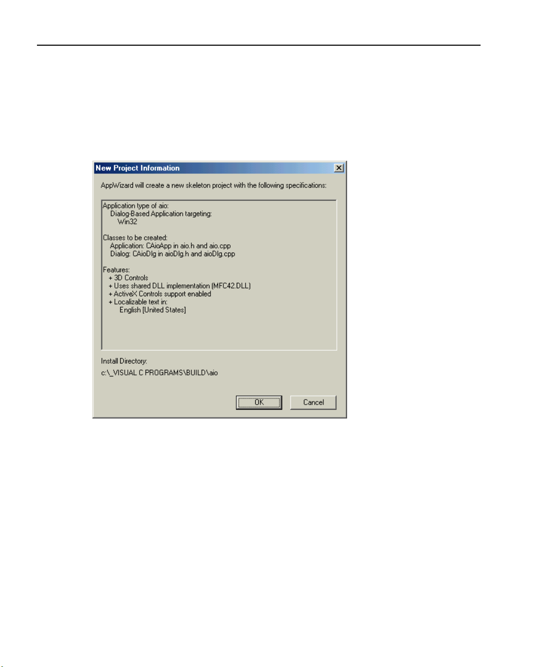
4. The MFC AppWizard will generate a dialog as shown in Figure 3-6. This box
lists a summary of the project that will be created. Click OK. The MFC AppWizard will build the foundation code.
Figure 3-6
New project information dialog
3-8
Page 29

DriverLINX Programming Tutorial Manual Accessing the DriverLINX Tools
5. Figure 3-7 shows the Visual C++ Development Studio project for the aio program with the File tab selected. Note the Source, Header and Resource files,
these will be edited to build the application.
Figure 3-7
Microsoft Development Studio File tab
3-9
Accessing Tools
Page 30

Accessing the DriverLINX Tools DriverLINX Programming Tutorial Manual
Building the dialog box
The first step of code development is building the visual panel, the 3-D controls that
will initiate and report program activity.
1. Choose Resource View.
2. If the dialog is not already visible, open the folders and double click the
IDD_AIO_DIALOG icon. The (TODO:Place dialog controls here) panel will
display along with the controls pallet, as shown in Figure 3-8.
Figure 3-8
Starting the dialog box
3-10
Page 31

DriverLINX Programming Tutorial Manual Accessing the DriverLINX Tools
3. Highlight the OK Button in the aio dialog box and choose delete. Do the same
for the Cancel Button and the Static Text so we have a clean dialog box to start
from.
4. Expand the dialog box to make it larger. From the Controls pallet, add five Push
Buttons, one Edit Box, and the Group Box as shown in Figure 3-9.
Figure 3-9
Adding the buttons
3-11
Accessing Tools
Page 32

Accessing the DriverLINX Tools DriverLINX Programming Tutorial Manual
5. Right Click on Button1. Choose Properties and edit the PushButton Properties
ID and Caption options as shown in Figure 3-10.
Figure 3-10
Setting button properties
3-12
Page 33

DriverLINX Programming Tutorial Manual Accessing the DriverLINX Tools
6. Repeat step 5 for PushButtons 2 through 5, using the properties shown below:
Initial Caption ID New Caption
Button1
IDC_Button1_StartAtoD Start A/D
Button2 IDC_Button2_ClearEditBox Clear
Button3 IDC_Button3_StartDtoA Start D/A
Button4 IDC_Button4_StopDtoA Stop D/A
Button5 IDC_Button5_Quit Quit
Static Text IDC_STATIC aio
7. For the Edit Box properties, check the Multiline and Vertical scroll check boxes
so multiple values can be displayed in the edit box, as shown in Figure 3-11.
Figure 3-11
Edit properties dialog
Accessing Tools
3-13
Page 34

Accessing the DriverLINX Tools DriverLINX Programming Tutorial Manual
8. Next, use the ClassWizard to place code for these controls in the program. The
ClassWizard is also used to set up Windows Messaging and assign a variable
name to the edit box. Refer to Figure 3-12 and perform steps 9 to 11.
Figure 3-12
Adding button functions
3-14
Page 35

DriverLINX Programming Tutorial Manual Accessing the DriverLINX Tools
Adding windows messaging
9. From the View Tab, Select ClassWizard, note that we are in the Message Maps
TAB of the ClassWizard. The CaioDlg Object ID should be highlighted. In the
Messages window, scroll down and select WindowProc. Choose Add Function.
WindowProc will appear in the Member Functions window. Choose OK. This
added function dispatches messages through the message map, an extremely
important part of the program.
Adding code blocks for the push buttons
10. From the View Tab, select ClassWizard and highlight the
IDC_Button1_StartAtoD selection in the Object ID’s box. Highlight
BN_Clicked in the Messages Box and choose Add Function, then OK. Repeat
this for each of the Push Buttons listed in the Object ID’s box.
Adding a variable for the edit box
11. Before closing the MFC ClassWizard, choose the Member Variables Tab.
Highlite IDC_Edit2 in the Controls ID window and select Add Variable. Assign
a member variable name of m_editBox, and choose OK. Choose OK once more
to close the MFC ClassWizard.
Adding code
Figure 3-13 and Figure 3-14 show the aioDlg.cpp and aioDlg.h files as they exist in
the application at this time. These are the only files that need to be edited to add all
required code for the Service Request. The code to be added is broken into 13 parts.
This demonstrates how to build an application after the AppWizard portion is
complete.
The 13 code fragments are provided at the end of this example in “Sample code
fragments.”
Code part 14 is not a code fragment that must be added, but is simply a reminder to
add the DriverLINX library file, DRVLNX32.lib, to the project. This file is normally
located in C:\DrvLINX4\DLApi\DRVLNX32.lib. To add this file, select Project > Add
to Project > Files from the menu bar.
Refer to Figure 3-13 and Figure 3-14 and place the 13 code parts in the appropriate
locations in the AIODgl.cpp and AIODlg.h files.
3-15
Accessing Tools
Page 36

Accessing the DriverLINX Tools DriverLINX Programming Tutorial Manual
Figure 3-13
aioDlg.cpp file cope addition points
3-16
Page 37

DriverLINX Programming Tutorial Manual Accessing the DriverLINX Tools
Figure 3-14
aioDlg.h file code addition points
Note that the DRVLNX32.lib file has been placed in the project. Once the project has
been compiled, there is an additional folder, External Dependencies, in the aio files.
For the data to report vertically in the Edit Box, you must edit the properties: Multiline
and Vertical scroll bars.
3-17
Accessing Tools
Page 38

Accessing the DriverLINX Tools DriverLINX Programming Tutorial Manual
Running the application
Figure 3-15 shows the final application running.
Figure 3-15
Running the application
3-18
Page 39

DriverLINX Programming Tutorial Manual Accessing the DriverLINX Tools
Sample code fragments
Listed below are the program code parts that must be added to the locations shown in
Figure 3-13 and Figure 3-14.
//AIODLG.cpp//
//Start Step 1 Code: adding the math functions //
#include<math.h> /*math functions must be included*/
//End Step 1 Code: adding the math functions //
//Start Step 2 Code: initialization//
m_logicalDevice=0;
m_samples=1000;
m_driverInstance=OpenDriverLINX(m_hWnd,"KPCI3108");
m_AOsr=(DL_ServiceRequest*) new DL_ServiceRequest;
m_AIsr=(DL_ServiceRequest*) new DL_ServiceRequest;
memset(m_AIsr,0,sizeof(DL_ServiceRequest));
DL_SetServiceRequestSize(*m_AIsr);
memset(m_AOsr,0,sizeof(DL_ServiceRequest));
DL_SetServiceRequestSize(*m_AOsr);
m_AOsr->operation=INITIALIZE;
m_AOsr->device=m_logicalDevice;
m_AOsr->mode=OTHER;
m_AOsr->hWnd=m_hWnd;
DriverLINX(m_AOsr);
showMessage(m_AOsr);
m_DLmsg=RegisterWindowMessage(DL_MESSAGE);
//End Step 2 Code: initialization//
Accessing Tools
//Start Step 3 Code://
void CAioDlg::showMessage(DL_ServiceRequest *SR)
{
SR->operation=MESSAGEBOX;
DriverLINX(SR);
}
//End Step 3 Code://
//Start Step 4 Code://
void CAioDlg::clearBuffers(DL_ServiceRequest *SR)
3-19
Page 40

Accessing the DriverLINX Tools DriverLINX Programming Tutorial Manual
{
if(SR!=NULL)
{
if(SR->lpBuffers!=NULL)
{
if(SR->lpBuffers->BufferAddr[0]!=NULL)
{
BufFree(SR->lpBuffers->BufferAddr[0]);
SR->lpBuffers->BufferAddr[0]=NULL;
}
delete SR->lpBuffers;
SR->lpBuffers=NULL;
}
}
}
//End Step 4 Code://
//Start Step 5 code://
void CAioDlg::done()
{
float *readings;
readings = new float[m_samples];
CString temp,fullstr;
int index;
m_AIsr->operation=CONVERT;
m_AIsr->mode=OTHER;
m_AIsr->start.typeEvent=DATACONVERT;
m_AIsr->start.u.dataConvert.startIndex=0;
m_AIsr->start.u.dataConvert.nSamples=m_samples;
m_AIsr->start.u.dataConvert.numberFormat=tSINGLE;
m_AIsr->start.u.dataConvert.offset=0.0f;
m_AIsr->start.u.dataConvert.scaling=0.0f;
m_AIsr->start.u.dataConvert.wBuffer=0;
m_AIsr->start.u.dataConvert.lpBuffer=readings;
DriverLINX(m_AIsr);
showMessage(m_AIsr);
m_editBox="";
fullstr="";
for(index=0;index<m_samples;index++)
3-20
Page 41

DriverLINX Programming Tutorial Manual Accessing the DriverLINX Tools
{
temp.Format("%f %d\r\n",readings[index],index);
fullstr+=temp;
}
m_editBox=fullstr;
UpdateData(FALSE);
delete [] readings;
}
//End Step 5 Code://
//Start Step 6 Code://
if(message==m_DLmsg)
{
switch(wParam)
{
case DL_BUFFERFILLED:
done();
break;
}
}
//End Step 6 Code://
//Start Step 7 Code: Start the Analog Acquisitiion//
clearBuffers(m_AIsr);
m_AIsr->operation=START;
m_AIsr->subsystem=AI;
m_AIsr->mode=INTERRUPT;
m_AIsr->start.typeEvent=COMMAND;
m_AIsr->timing.typeEvent=RATEEVENT;
m_AIsr->stop.typeEvent=TCEVENT;
m_AIsr->channels.nChannels=1;
m_AIsr->channels.chanGain[0].channel=0;
m_AIsr->channels.chanGain[0].gainOrRange=Gain2Code(m_logicalDevice,AI,-1.0);
m_AIsr->channels.numberFormat=tNATIVE;
m_AIsr->lpBuffers=(DL_BUFFERLIST*) new BYTE[DL_BufferListBytes(1)];
m_AIsr->lpBuffers->notify=NOTIFY;
m_AIsr->lpBuffers->nBuffers=1;
m_AIsr->lpBuffers->bufferSize=Samples2Bytes(m_logicalDevice,AI,0,m_samples);
3-21
Accessing Tools
Page 42

Accessing the DriverLINX Tools DriverLINX Programming Tutorial Manual
m_AIsr->lpBuffers->BufferAddr[0]=BufAlloc(GBUF_INT,m_AIsr->lpBuffers->bufferSize);
m_AIsr->timing.u.rateEvent.channel=DEFAULTTIMER;
m_AIsr->timing.u.rateEvent.mode=RATEGEN;
m_AIsr->timing.u.rateEvent.clock=INTERNAL1;
m_AIsr->timing.u.rateEvent.gate=DISABLED;
m_AIsr->timing.u.rateEvent.period=Sec2Tics(m_logicalDevice,AI,INTERNAL1,0.00001f);
m_AIsr->timing.u.rateEvent.pulses=0;
m_AIsr->hWnd=m_hWnd;
DriverLINX(m_AIsr);
showMessage(m_AIsr);
//End Step 7 Code: Start the Analog Acquisitiion//
//Start Step 8 Code: Clear the Edit Box//
m_editBox="";
UpdateData(FALSE);
MessageBeep((WORD)-1);
//End Step 8 Code: Clear the Edit Box //
//Start Step 9 Code:Start the Analog Output//
clearBuffers(m_AOsr);
float *sinebuf;
sinebuf=new float[m_samples];
int i;
for(i=0;i<m_samples;i++)
{
sinebuf[i]=(float) sin(i*2*3.14159/m_samples);
}
m_AOsr->operation=CONVERT;
m_AOsr->device=m_logicalDevice;
m_AOsr->subsystem=AO;
m_AOsr->mode=OTHER;
m_AOsr->start.typeEvent=DATACONVERT;
m_AOsr->lpBuffers=(DL_BUFFERLIST*) new BYTE[DL_BufferListBytes(1)];
m_AOsr->lpBuffers->nBuffers=1;
m_AOsr->lpBuffers->bufferSize=Samples2Bytes(m_logicalDevice,AO,0,m_samples);
m_AOsr->lpBuffers->BufferAddr[0]=BufAlloc(GBUF_INT,m_AOsr->lpBuffers->bufferSize);
m_AOsr->lpBuffers->notify=NULL;
m_AOsr->channels.nChannels=2;//1;
m_AOsr->channels.chanGain[0].channel=0;
m_AOsr->channels.numberFormat=tNATIVE;
3-22
Page 43

DriverLINX Programming Tutorial Manual Accessing the DriverLINX Tools
m_AOsr->start.u.dataConvert.startIndex=0;
m_AOsr->start.u.dataConvert.nSamples=m_samples;
m_AOsr->start.u.dataConvert.numberFormat=tSINGLE;
m_AOsr->start.u.dataConvert.scaling=0.0f;
m_AOsr->start.u.dataConvert.offset=0.0f;
m_AOsr->start.u.dataConvert.wBuffer=0;
m_AOsr->start.u.dataConvert.lpBuffer=sinebuf;
DriverLINX(m_AOsr);
showMessage(m_AOsr);
m_AOsr->operation=START;
m_AOsr->device=m_logicalDevice;
m_AOsr->subsystem=AO;
m_AOsr->mode=INTERRUPT;
m_AOsr->start.typeEvent=COMMAND;
m_AOsr->timing.typeEvent=RATEEVENT;
m_AOsr->timing.u.rateEvent.channel=DEFAULTTIMER;
m_AOsr->timing.u.rateEvent.mode=RATEGEN;
m_AOsr->timing.u.rateEvent.clock=INTERNAL1;
m_AOsr->timing.u.rateEvent.gate=DISABLED;
m_AOsr->timing.u.rateEvent.period=Sec2Tics(m_logicalDevice,AO,INTERNAL1,0.00001f);
m_AOsr->timing.u.rateEvent.pulses=0;
m_AOsr->stop.typeEvent=COMMAND;
DriverLINX(m_AOsr);
showMessage(m_AOsr);
//End Step 9 Code:Start the Analog Output//
Accessing Tools
//Start Step 10 Code: Stop the Analog Output//
m_AOsr->operation=STOP;
DriverLINX(m_AOsr);
showMessage(m_AOsr);
//End Step 10 Code: Stop the Analog Output//
//Start Step 11 Code: Code block for the QUIT Button//
clearBuffers(m_AOsr);
clearBuffers(m_AIsr);
delete m_AOsr;
m_AOsr=NULL;
delete m_AIsr;
m_AIsr=NULL;
CloseDriverLINX(m_driverInstance);
3-23
Page 44

Accessing the DriverLINX Tools DriverLINX Programming Tutorial Manual
m_driverInstance=NULL;
OnOK();
//End Step 11 Code: Code block for the QUIT Button//
//AIODlg.h://
//Step 12 Code://
#include"c:\drvlinx4\dlapi\drvlinx.h"
#include"c:\drvlinx4\dlapi\dlcodes.h"
//Step 13 Code://
private:
int m_samples;
void done();
WORD m_DLmsg;
void clearBuffers(DL_ServiceRequest* SR);
int m_logicalDevice;
void showMessage(DL_ServiceRequest* SR);
DL_ServiceRequest* m_AIsr; //Declare SS Structure
DL_ServiceRequest* m_AOsr;
HINSTANCE m_driverInstance; //To contain Instance Handle
//Step 14 Code://
//Add the DriverLINX library file to the project, C:\DrvLINX4/DLApi/DRVLNX32.lib
Borland Delphi
Borland programming environments interact with DriverLINX through an ActiveX
control. Sample programs written in Delphi are installed when the DriverLINX driver
is installed. These are located in the C:\DrvLINX4\Source directory by default.
3-24
Page 45

DriverLINX Programming Tutorial Manual Accessing the DriverLINX Tools
Adding the ActiveX controls is very similar to the procedure for Visual Basic, but
there are some differences. Perform the following procedure to install the ActiveX
controls.
1. Start the Borland Delphi program.
2. From the Component menu select Import ActiveX. The Import ActiveX dialog
shown in Figure 3-16 will appear.
3. In the alphabetical list of controls, select the DriverLINX ActiveX Controls.
4. Note the names listed in the Class names box. Delphi 5.0 will typically use the
names TDriverLINXSR and TDriverLINXLDD. Any class name can be used.
However, when moving applications to another computer, the class names must
be the same between the two computers to share the application. The sample
programs provided on the Keithley Instruments web site are created with the
class names TDriverLINXSR and TDriverLINXLDD. To change the name of
an installed control, it must be removed and reinstalled with the new name.
5. Click the Install button to close the Import ActiveX dialog.
6. Click the OK button to close the Install Components dialog.
Figure 3-16
Borland Delphi 5 Import ActiveX dialog
Accessing Tools
3-25
Page 46

Accessing the DriverLINX Tools DriverLINX Programming Tutorial Manual
3-26
Page 47

4
Learning DriverLINX
4-1
Learning DriverLINX
Page 48

Learning DriverLINX DriverLINX Programming Tutorial Manual
DriverLINX design philosophy
DriverLINX is designed as a high-performance data acquisition device driver for 32bit version of Microsoft Windows. The DriverLINX API is device independent, lending to the development of device independent portable code. DriverLINX is multi-user
and multi-tasking, allowing both foreground and background tasks. It allows for multiple programs to access the data acquisition boards simultaneously, if supported by
the board.
Due to the device independent nature of DriverLINX, it implements more functions
than are available in any single data acquisition board. As a result, any individual
board can only use a subset of the DriverLINX full function set. To find the specific
functions of DriverLINX supported by an individual data acquisition board, refer to
the Using DriverLINX with Your Hardware manual for that board.
To aid in developing device independent code, DriverLINX provides a control called
the Logical Device Descriptor (LDD). The LDD contains information regarding the
physical capabilities of the hardware, including the number and type of channels,
operating modes, and others. Applications written with DriverLINX can dynamically
obtain information about the data acquisition hardware from the LDD, rather than
hard coding for a specific board. The application can then be moved to a different
environment with different hardware and still function, provided that the installed
board meets the minimum requirements of your application.
DriverLINX does not require the use of the Logical Device Descriptor when creating
applications. It is provided as an aide for developing portable applications. When
learning to program DriverLINX applications, it is a good idea to avoid the LDD. As
you learn more about DriverLINX and grow more comfortable with the DriverLINX
API, you can add the LDD capabilities to create more flexible, robust applications.
The sample programs provided with DriverLINX are created using the LDD to take
advantage of the full capabilities of whatever data acquisition hardware is installed on
the system.
4-2
Page 49

DriverLINX Programming Tutorial Manual Learning DriverLINX
Devices, subsystems, and channels
There are three logical levels used to control data acquisition boards when programming with DriverLINX. These are the logical device, subsystem, and channel. When
performing any task with DriverLINX, all three of these must be specified.
For information on how DriverLINX assigns logical devices, subsystems, and channels for a particular data acquisition board, refer to the Using DriverLINX with Your
Hardware manual specific to that board. This manual will list all logical subsystems
and channels defined for that board, along with the corresponding physical channels,
connectors, and signals.
Logical devices
The logical device corresponds to the physical data acquisition board itself. Systems
with more than one data acquisition board will have more than one logical device. The
logical device is used to tell DriverLINX which data acquisition board will be used.
There is a maximum of six devices per family, indicated by the driver name, installed
at one time. The device numbers should start at zero and increment by one. It is legal
to have more than one device numbered zero as long as they correspond to boards
from different board families (driver names).
Logical subsystems
The logical subsystem refers to the general function that will be performed. For example, when performing analog input operations, the analog input subsystem is used.
DriverLINX considers each data acquisition board to have the following subsystems:
• System – Refers to the actual data acquisition board itself.
• Analog input – Refers to the A/D converters, multiplexers, and associated
hardware.
• Analog output – Refers to the D/A converters and associated hardware.
• Digital input – Refers to the digital input ports and associated hardware.
• Digital output – Refers to the digital output ports and associated hardware.
• Counter/timer – Refers to the counter/timer channels and associated hardware.
4-3
Learning DriverLINX
Page 50

Learning DriverLINX DriverLINX Programming Tutorial Manual
Logical channels
Logical channels refer to the addressable hardware channels of each subsystem. For
most analog and digital subsystems, the logical channel assignment is very straightforward. Logical channel assignments usually match the physical channel assignments. For example, physical analog input channel 0 is assigned to logical channel 0.
DriverLINX may assign a logical channel to items which are not normally thought of
as channels. This is most noticeable with counter/timer functions. For example, DriverLINX may assign a 1-bit digital logical channel to external hardware trigger input
lines.
For counter/timer subsystems, the logical channel assignments can be more complex.
In some cases, multiple logical channels may be assigned to a single physical channel.
This may occur when a hardware channel has multiple operating modes. A logical
channel may be assigned to each individual counter/timer when operating independently, and another logical channel may be assigned when two counters are used in a
cascaded mode. (KPCI-3108 series boards implement this for the counter/timer subsystem.)
In some cases, DriverLINX may assign multiple physical channels to a single logical
channel. This occurs when the physical channels cannot be operated independently. In
this case, DriverLINX will assign all such physical channels to a single logical channel for ease of operation.
Understanding the Service Request
Overview
A Service Request is a data structure or control created by an application that provides
DriverLINX with all the information it needs to perform a task.
DriverLINX uses a data, or table, oriented approach to tasks, as opposed to a procedural approach. Using DriverLINX, it is not necessary to specify all the steps to be
performed to complete a task. Rather, all the required data needed by the task is
assigned to the table or control. The data is then sent to DriverLINX all at once.
Depending on the programming language, this is done either with a single function
call or using the control’s refresh method. DriverLINX takes care of the rest.
4-4
Page 51
DriverLINX Programming Tutorial Manual Learning DriverLINX
Not all DriverLINX tasks will use all properties of the Service Request. The properties
used are determined by the individual task being performed. Detailed information on
the Service Request can be found in the DriverLINX Technical Reference Manual in
Section 6 - Service Requests, and in the DriverLINX/VB Technical Reference Manual
in Section 6 - Service Request Control. All unused properties should be initialized to a
defined value, such as zero. This will prevent problems in case updated version of the
DriverLINX drivers use previously undefined properties.
The Service Request is depicted graphically by DriverLINX using the Edit Service
Request dialog, shown in Figure 4-1. Not all properties of the Service Request dialog
are displayed in the Edit Service Request dialog. The properties that are not displayed
are assigned dynamically at run-time.
Two ways to display the Edit Service Request dialog are by using the LearnDL application, and by calling it directly from an application. Both of these methods are discussed later in this section.
Figure 4-1
Edit Service Request dialog
The properties of the Service Request are broken into five separate groups. These
groups are the Control, Request, Events, Select, and Results groups. The following is
a brief description of these groups.
4-5
Learning DriverLINX
Page 52

Learning DriverLINX DriverLINX Programming Tutorial Manual
Control Group
VB
The Control group is only used when using the ActiveX controls of the DriverLINX.
This group contains standard control properties, such as the control name, window
handle, and control design-time coordinates. These properties do not directly affect
data acquisition tasks. The Control group is not displayed in the Edit Service Request
dialog.
Request Group
The Request group contains data specifying the device and subsystem being used, the
data acquisition mode, and the operation being performed. When programming in C/
C++ the Request group also contains the window handle, since C/C++ does not use
the Control group. The Request group is displayed at the top of the Edit Service
Request dialog.
Of all the groups in a Service Request, only the Request group is required for all services. The fields of the Events and Select groups are used selectively depending on the
particular task requested of DriverLINX.
Events Group
The Events group contains properties controlling the timing of the data acquisition,
and the start and stop events for the task. This group is displayed in the center portion
of the Edit Service Request dialog. There are several classes of events that can be
assigned to the timing, start, and stop properties. These classes are simple, analog,
digital, rate, and setup.
The simple events are events that do not require additional properties. These include
null events, command events, and terminal count events. Command events are software generated start and stop events. Terminal count events are used when the task
should automatically stop after one trip through the data buffers.
Analog events perform real-time (board level hardware/firmware) monitoring of an
analog input channel for the occurrence of the specified signal condition. Depending
on the features of your hardware, analog events can be used as start and stop events,
and may use a delay.
4-6
Page 53

DriverLINX Programming Tutorial Manual Learning DriverLINX
Digital events perform real-time monitoring of a digital input channel and signal when
the channel meets the specified condition. Digital events use a mask to specify which
bits to monitor, and a pattern to which they are compared. The comparison can be an
equals or not equals condition. The mask and pattern properties control rising and falling edge sensitivities.
Rate events can be used as timing events or counter/timer setup events. Timing events
pace or clock the data acquisition task. Counter/timer setup events can specify frequency and time interval measurements and event counters.
Setup events configure digital I/O ports. Configuration events are hardware specific.
Refer to the Using DriverLINX with Your Hardware manual for information on config-
uration events supported by a specific data acquisition board.
DriverLINX supports many start and stop events. To determine which events are supported by a particular data acquisition board, refer to the Using DriverLINX with Your
Hardware manual.
Select Group
The Select group defines the channels and data buffers to be used for the task. In addition, a flag property is provided to allow the disabling of some DriverLINX message
notifications in specific circumstances.
The channel properties of the Select group specify the logical channel to be used, the
gain for the channel, and the number format of the data. Depending on the hardware
capabilities, it may be possible to specify a single channel, a range of channels or a
channel-gain list. If the hardware does not directly support a channel-gain list, this
feature may not be used.
The data buffers properties of the Select group specify the number and size of the data
buffers to be used for the data acquisition task. The actual number of buffers supported
by DriverLINX varies with the specific version. The exact number may be obtained
from the Logical Device Descriptor (LDD). For information on the LDD, refer to the
DriverLINX Technical Reference Manual in Section 7 - Logical Device Descriptors, or
the DriverLINX/VB Technical Reference Manual in Section 7 - Logic Device Descrip-
tor Control.
The flags properties of the Select group allow the disabling of event flags. These flags
can be enabled to improve performance of DriverLINX in certain circumstances. This
4-7
Learning DriverLINX
Page 54

Learning DriverLINX DriverLINX Programming Tutorial Manual
may be helpful when repeatedly polling for a small number of samples. For more
information on these flags, refer to the DriverLINX/VB Technical Reference Manual.
The Select group is represented in the Service Request dialog, shown in Figure 4-1, in
a different manner than the other groups. The right side of the center of the window
contains the first portion of the Select group, labeled Select>>. This series of three
radio buttons controls which properties are displayed in the bottom of the Edit Service
Request dialog. Selecting the Channels, Buffers, or Flags radio button displays the
respective properties in the bottom of the dialog. To display a different set of properties, select the appropriate radio button.
Results Group
The Results group contains the results of the task returned by DriverLINX. Using the
Results group, DriverLINX returns the status of the task and various information
regarding the buffers and the data in the buffers. The actual information returned
depends on the type of task performed. The Results group is not displayed in the Edit
Service Request dialog.
Auditing the Service Request
DriverLINX automatically performs an audit, or error checking process, on all Service
Requests. This process verifies that all the values passed to DriverLINX are valid. The
values are verified against the device information stored in the Logical Device
Descriptor. The audit process helps prevent problems resulting from executing Service
Requests with invalid data.
Service Requests can be audited without being executed. Setting the property
Req_op_auditOnly to DL_True when calling a Service Request will audit, but not execute, the Service Request. If the audit process detects any problems with the Service
Request, DriverLINX returns an error code. For information on displaying and interpreting error codes, refer to Section 9, Troubleshooting, of this manual.
4-8
Page 55

DriverLINX Programming Tutorial Manual Learning DriverLINX
Learning to use the Service Request
DriverLINX provides some tools to help learn to use the Service Request. These tools
include the Edit Service Request dialog and the LearnDL application.
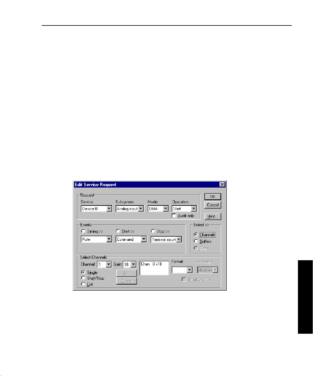
The Edit Service Request dialog, shown in Figure 4-2, is an interactive method of filling out a Service Request. As choices are made, the dialog changes to show the appropriate controls available for the current selections. Controls are added and removed in
response to selections. The Edit Service Request dialog will only show controls and
choices valid for the selected device. If a given set of selections can be made in the
Edit Service Request dialog, then the same configuration may achieved when
programming.
Figure 4-2
Edit Service Request dialog
4-9
Learning DriverLINX
Page 56
Learning DriverLINX DriverLINX Programming Tutorial Manual
Displaying the Edit Service Request dialog with LearnDL
The easiest way to display and learn to use the DriverLINX Edit Service Request dialog is through the LearnDL application. LearnDL is installed when the DriverLINX
driver itself is installed. A shortcut to LearnDL is created in the DriverLINX program
group. The LearnDL application is designed to step you through all the actions
required to acquire data using DriverLINX.
The LearnDL application can be very useful for a new DriverLINX programmer.
LearnDL provides access to almost all of DriverLINX’s features. This allows you to
test the data acquisition hardware and ensure DriverLINX is installed and functioning
properly. In some cases LearnDL may be used by technical support to assist in setting
up and troubleshooting the data acquisition hardware and DriverLINX. More information regarding the LearnDL application can be found in Section 9, Troubleshooting, of
this manual.
The following procedure demonstrates using LearnDL to perform a simple analog
input operation using the Edit Service Request dialog.
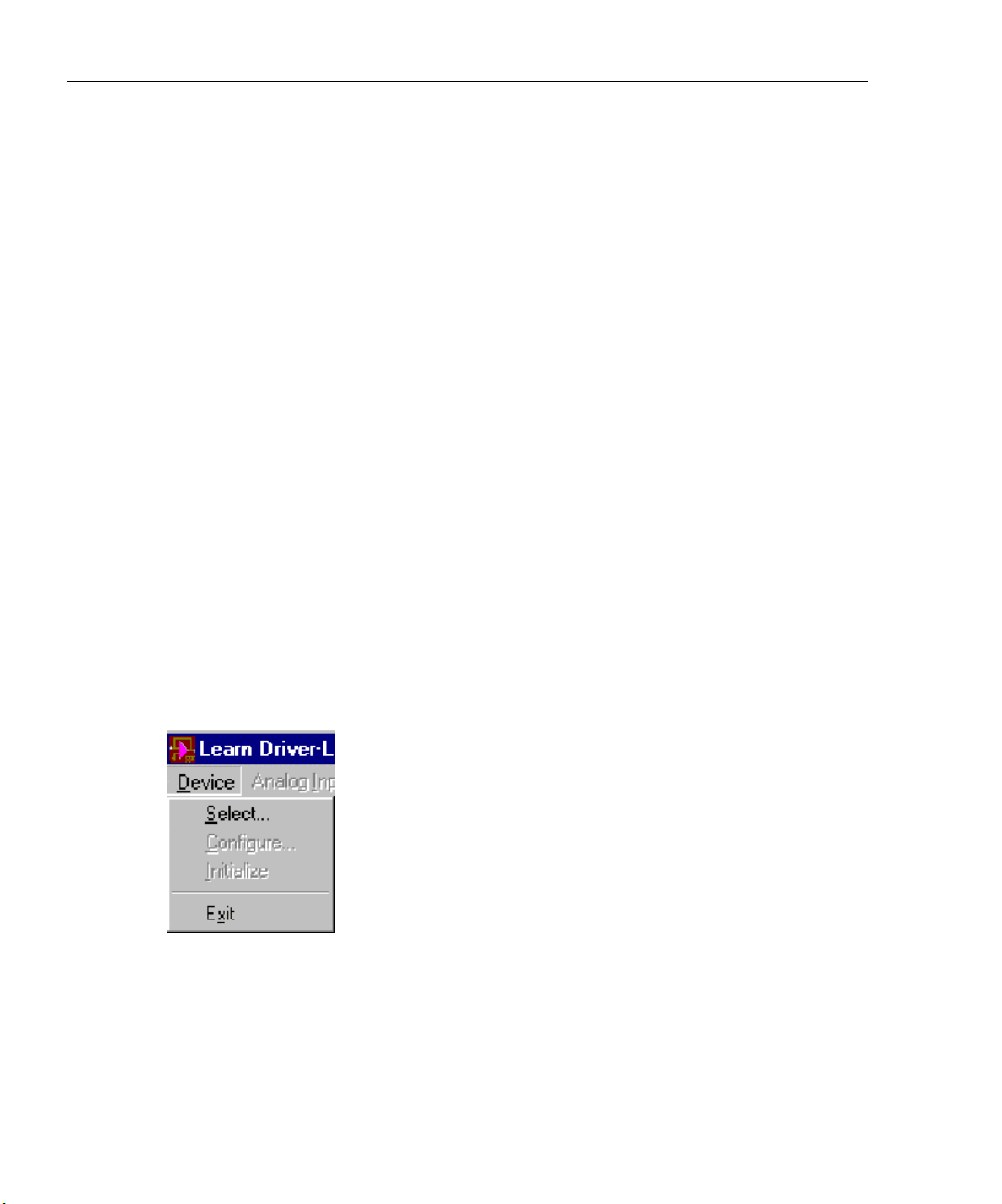
1. From the LearnDL main window, click the Device menu. The menu shown in
Figure 4-3 appears. Notice that the only menu choice enabled is Select. You
must first tell DriverLINX what device you will be using before you can do
anything with the device. Click the Select option.
Figure 4-3
LearnDL Device menu
4-10
Page 57

DriverLINX Programming Tutorial Manual Learning DriverLINX
2. When the Select Device window appears, as shown in Figure 4-4, select the
desired logical device. Unless more than one data acquisition board is installed,
the logical device should be zero. Click the OK button to select the device and
close the window.
Figure 4-4
Select Device window
3. From the LearnDL main window, click the Device menu. Notice that the Configure and Initialize choices are now available. It is not necessary to configure
the device before using it unless the data acquisition task requires a new configuration. Click the Initialize option to set the device to a known state. The Initialize option of the Device menu can also be used to abort any current task.
4. From the Analog Input menu, select Initialize. This will perform a software
reset of the subsystem on the selected device. Notice that before the Initialize
option is selected, all other options for that subsystem are disabled.
4-11
Learning DriverLINX
Page 58

Learning DriverLINX DriverLINX Programming Tutorial Manual
5. From the Analog Input menu, select Edit/execute. This will open the Edit Service Request dialog shown in Figure 4-5. Note that there are very few selections
available when the dialog opens. As choices are made, additional options will
become enabled as appropriate.
Figure 4-5
Edit Service Request dialog
6. Fill out the Edit Service Request dialog as shown in Figure 4-6. These settings
instruct DriverLINX to take an analog reading on channel 0.
Figure 4-6
Completed Edit Service Request dialog
4-12
Page 59

DriverLINX Programming Tutorial Manual Learning DriverLINX
7. To instruct DriverLINX to execute the Service Request, click the OK button.
This will close the Edit Service Request dialog and execute the Service
Request. When the Service Request is complete, the LearnDL window will
update to show the results of the Service Request. This specific Service Request
performs a task that acquires 500 data points from analog input channel 0. The
data points are graphed on a digital oscilloscope display, as shown in
Figure 4-7.
Figure 4-7
Oscilloscope display
8. The Service Request can be executed again by selecting Start from the Analog
Input menu, or clicking the Acquire button.
9. If the Service Request takes an extended period of time to execute, it can be
stopped by clicking the Stop button, or selecting Stop from the Analog Input
menu. If a task is not currently running when the Stop button is clicked, a
DriverLINX error will be displayed.
4-13
Learning DriverLINX
Page 60

Learning DriverLINX DriverLINX Programming Tutorial Manual
Displaying the Edit Service Request dialog from within an application
DriverLINX allows an application to display the Edit Service Request dialog at runtime. This feature of DriverLINX is very useful when programming. Several properties can be assigned to a Service Request, then the Edit Service Request box can be
displayed to check how DriverLINX applied the properties to the Service Request.
Displaying the Edit Service Request dialog at run-time requires the setting of at least
two properties of the Service Request. The first property, Req_DLL_name must be set
to the specific DLL that controls the device to which the Service Request will be sent.
The second property is the Req_op_edit property. A call to DriverLINX using the
Refresh method with Req_op_edit set to True will display the Edit Service Request
dialog. When the user dismisses the dialog, Req_op_edit is set to False and DriverLINX returns a result code. If the user canceled the dialog, the Service Request is not
updated and DriverLINX returns an error. If no error was returned, the Service
Request is updated and can be executed by another call to DriverLINX with the
Refresh method.
The following source code examples demonstrate how to display the Edit Service
Request dialog.
VB
Visual Basic
' Assumes the SR.Req.DLL.Name property is already set to the driver name
' Use this procedure to show the Edit Service Request dialog
Function ShowEditSR (SR As DriverLINXSR) As Integer
' Caller should set up a Service Request
SR.Req_op_edit = DL_True
SR.Refresh
' DriverLINX automatically removes the Req_op_edit flag
' Caller can execute SR if there are no errors
ShowEditSR = SR.Res_result
End Function
4-14
Page 61

DriverLINX Programming Tutorial Manual Learning DriverLINX
C/C++
C/C++
//***********************************************************
// Use this procedure to show the Edit Service Request dialog
//***********************************************************
UINT ShowEditSR (LPServiceRequest pSR)
{
// Caller sets up Service Request
pSR->operation = (Ops)(pSR->operation | EDIT);
// DriverLINX automatically removes the EDIT flag
// Caller can execute SR if there are no errors
return DriverLINX(pSR)
}
DriverLINX source file examples
During the installation of the DriverLINX drivers, a wide selection of sample programs are installed. These programs are provided in several different programming
languages, including VB, Delphi, and C++. Not all examples are provided in all programming languages.
The sample programs are designed to be very robust programs. Through the use of the
DriverLINX Logical Device Descriptor, or LDD, these sample programs will function
on any supported data acquisition board. The LDD control contains information
regarding the capabilities of the data acquisition boards installed on the computer. A
DriverLINX application can query the LDD to retrieve the hardware capabilities of
the board. The use of the LDD is not covered in this tutorial manual. For information
regarding the LDD, refer to the Analog I/O Programming Guide.
When learning to program DriverLINX the sample programs are generally not a good
place to start. These samples are written from a very high level and assume a strong
background in programming. The examples also use numerous function calls which
can hide what is happening when the example executes. In addition, the extensive use
of the LDD further obscures what is really happening.
The sample programs are separated according to the subsystem to which they apply.
Some examples illustrate the integration of more than one subsystem. The samples
provided may change with each version of DriverLINX. By default, the DriverLINX
source code examples are installed in the C:\DrvLINX4\Source folder.
4-15
Learning DriverLINX
Page 62

Learning DriverLINX DriverLINX Programming Tutorial Manual
Analog input subsystem
AISingle — Demonstrates how to acquire a single sample of analog input data.
AIScan — Demonstrates how to acquire a single scan of analog input data from a list
of analog input channels.
AIBuffer — Demonstrates how to acquire a single buffer of analog input data from an
analog input channel.
AIMultch — Demonstrates how to acquire a single buffer of analog input data that
contains data from multiple analog input channels. Note that this example demonstrates how to implement a channel gain list as opposed to a start-stop list.
AINonstp — Demonstrates how to acquire a single channel of analog input data continuously by using multiple buffers.
AIDigTrg — Similar to AIBuffer except that it demonstrates how to implement a digital start event.
AIDStpTg — Similar to AIBuffer except that it demonstrates how to implement a
digital stop event.
AIBurst — Demonstrates how to acquire a single buffer of analog input data that contains data from multiple analog input channels. Note that this program demonstrates
how to implement a burst-mode timing event.
AIATrig — Similar to AIBuffer except that it demonstrates how to implement an analog start event. Note that very few boards support this option. Consult your hardware
manual for more information concerning the implementation of this feature.
AIStpTrg — Similar to AIBuffer except that it demonstrates how to implement an
analog stop event. Note that very few boards support this option. Consult your hardware manual for more information concerning the implementation of this feature.
AIStream — Demonstrates how to continuously stream analog input data to disk.
TCGains — Demonstrates how to set up specialized gain codes that set the type,
engineering units and other properties of a DAS-TC/B channel.
4-16
Page 63

DriverLINX Programming Tutorial Manual Learning DriverLINX
Analog output subsystem
AOSingle — Demonstrates how to write a single sample to an analog output.
AOBuffer — Demonstrates how to write a single buffer of analog data to an analog
output channel.
AOMultch — Demonstrates how to write a single buffer of analog data to multiple
analog output channels.
AONonstp — Demonstrates how to write continuously to a single analog output
channel by using multiple buffers.
AODigTrg — Similar to AOBuffer except it demonstrates how to implement a digital
start event.
Analog I/O subsystems
AISyncAO — Demonstrates how to synchronize acquiring analog input while outputting analog output. This task is accomplished by the analog output subsystem using
the clock source as the analog input subsystem.
Digital input subsystem
DISingle — Demonstrates how to acquire a single sample of digital input data.
DIBuffer — Demonstrates how to acquire a single buffer of digital input data from a
digital input channel.
DISysclk — Similar to DIBuffer except it uses the system clock as the pacer clock for
acquiring a buffer of digital input data from the digital input subsystem. Note that not
all boards support this functionality.
DIMultch — Demonstrates how to acquire a single buffer of digital input data that
contains data from multiple digital input channels.
DINonstp — Demonstrates how to acquire a single channel of digital input data continuously by using multiple buffers.
4-17
Learning DriverLINX
Page 64

Learning DriverLINX DriverLINX Programming Tutorial Manual
DISimult — Demonstrates how to acquire a single buffer of data from multiple channels simultaneously by using your board's digital input subsystem.
DIExtend — Demonstrates how to acquire a single digital sample of data from your
board's digital input subsystem using extended I/O addressing. This allows the user to
isolate channels into sizes other than their native size.
Digital output subsystem
DOSingle — Demonstrates how to write a single sample to a digital output.
DOBuffer — Demonstrates how to write a single buffer of digital data to a digital out-
put channel.
DOSysclk — Similar to DOBuffer except it uses the system clock as the pacer clock
for writing a buffer of digital output data from the digital output subsystem. Note that
not all boards support this functionality.
DOMultch — Demonstrates how to write a single buffer of digital data to multiple
digital output channels.
DONonstp — Demonstrates how to write continuously to a single digital output
channel by using multiple buffers.
DOSimult — Demonstrates how to write a single buffer of data to multiple channels
simultaneously by using your board's digital output subsystem.
DOExtend — Demonstrates how to write a single digital sample of data to your
board's digital output subsystem using extended IO addressing. This allows the user to
isolated channels into sizes other than their native size.
4-18
Page 65

DriverLINX Programming Tutorial Manual Learning DriverLINX
Digital input/output subsystems
DIOCnfig — Demonstrates how to configure a digital channel as either a digital input
channel or a digital output channel. Note that this feature is not available to all boards.
Counter/timer subsystem
EventCtr — Demonstrates event counting of a single input signal using two counter/
timer channels. This program has only been developed for VB. Note that not all
boards support this functionality.
PerMeas — Demonstrates both period and pulse width measurement using two
counter/timer channels. This program has only been developed for VB. Note that not
all boards support this functionality.
FreqGen — Demonstrates rate, square-wave, and variable duty cycle frequency generation. This program has only been developed for VB. Note that not all boards support this functionality.
FreqMeas — Demonstrates frequency measurement using two or three counter/timer
channels. Requires an external connection from the interval timer channel's output to
the cycle counter channel's gate input. This program has only been developed for VB.
Note that not all boards support this functionality.
4-19
Learning DriverLINX
Page 66

Learning DriverLINX DriverLINX Programming Tutorial Manual
4-20
Page 67

5
Common
DriverLINX Tasks
Common Tasks
5-1
Page 68

Common DriverLINX Tasks DriverLINX Programming Tutorial Manual
Introduction
When creating a DriverLINX application, there are several tasks that need to be performed regardless of the purpose of the application. These tasks include opening and
closing the DriverLINX driver and initializing devices and subsystems.
Basic sequence of operations
All applications must follow the same basic sequence of operation to perform data
acquisition with DriverLINX. The following is the basic sequence of operations
required to perform a data acquisition task.
• Open the DriverLINX driver
• Initialize the device
• Perform the data acquisition task
• Close the DriverLINX driver
Complex applications may use additional steps, such as initializing subsystems, or
may perform some of these steps multiple times. The remainder of this section discusses the common basic steps, such as opening and closing the DriverLINX driver,
and initialization. Section 6, Analog and Digital I/O Programming, discusses the steps
involved in performing the data acquisition task itself.
5-2
Page 69

DriverLINX Programming Tutorial Manual Common DriverLINX Tasks
VB
Opening the DriverLINX driver
Before an application can communicate with a data acquisition board, it must specify
the driver to be used. If a driver is not specified, or if the specified driver is invalid, the
Open DriverLINX dialog shown in Figure 5-1 will appear at run-time. The user may
then pick a driver from a list of installed drivers.
Figure 5-1
Open DriverLINX dialog
Common Tasks
Visual Basic
Specifying the driver when using Visual Basic requires specifying the name of the
driver. A separate instance of the control should be created for each driver opened.
When calling functions, the control will automatically select the appropriate driver.
DriverLINXSR_object.Req_DLL_name = “driver”
5-3
Page 70

Common DriverLINX Tasks DriverLINX Programming Tutorial Manual
C/C++
C/C++
Use the following with driver name to avoid the OpenDriverLINX dialog.
// For KPCI-3101/2/3/4 or KPCI-3110/3116, driver name is kpci3100
// For KPCI-3107/8, driver name is kpci3108
// For KPCI-3160, driver name is kpci3160
// For PCI PIO products, driver name is kpcipio
// For ISA PIO products, driver name is kmbpio
HINSTANCE m_driverInstance;
m_driverInstance = OpenDriverLINX(m_hWnd, "driver");
m_pSR = (DL_ServiceRequest*) new DL_ServiceRequest;
//allocate memory for the service request
memset(m_pSR,0,sizeof(DL_ServiceRequest));
//reset the members of the service request to defaults
DL_SetServiceRequestSize(*m_pSR);
Initialzing a device
Initializing a device is a way of resetting the device and all subsystems to a known
state. This should be done immediately after opening the DriverLINX driver.
Due to the multi-tasking and multi-device nature of DriverLINX, the exact outcome of
initializing a device can vary. In the simplest sense, where a single process is using a
single device, initializing that device will cancel all active Service Requests and perform a software reset of all subsystems. All outputs will be set to zero if this was the
first initialization after loading the driver, or to the last known value otherwise.
Performing an initialization when multiple processes are using the same device will
have one of the following effects:
• If another process is executing a Service Request on the device, DriverLINX
performs all portions of the initialization that do not interfere with the other
process. DriverLINX then returns a Device Busy error.
• If multiple processes are sharing the device, DriverLINX will not perform the
initialization.
5-4
Page 71

DriverLINX Programming Tutorial Manual Common DriverLINX Tasks
VB
Visual Basic
C/C++
The following code example demonstrates initializing the device.
Function InitDriverLINXDevice(SR As DriverLINXSR, ByVal Device As Integer)
As integer
With SR
.Req_device = Device
' Device = integer number assigned in DriverLINX configuration
.Req_subsystem = DL_DEVICE
.Req_mode = DL_OTHER
.Req_op = DL_INITIALIZE
' No events, buffers, channels needed
.Evt_Tim_type = DL_NULLEVENT
.Evt_Str_type = DL_NULLEVENT
.Evt_Stp_type = DL_NULLEVENT
.Sel_buf_N = 0
.Sel_chan_N = 0
.Refresh
InitDriverLINXDevice = .Res_result
End With
End Function
C/C++
The following code example demonstrates initializing the device.
m_pSR->device=m_LogicalDevice;
// Device = integer number assigned in DriverLINX configuration
m_pSR->operation=INITIALIZE;
m_pSR->mode=OTHER;
m_pSR->subsystem=DEVICE;
m_pSR->hWnd=m_hWnd;
DriverLINX(m_pSR);
showMessage(m_pSR); //Show DriverLINX errors, if any
Common Tasks
5-5
Page 72

Common DriverLINX Tasks DriverLINX Programming Tutorial Manual
Initializing a subsystem
Initializing a subsystem resets the subsystem to a known state. This procedure is not
normally needed, since DriverLINX performs an initialization of all subsystems when
the device itself is initialized. Initializing a subsystem may be useful if another process
is using another subsystem on the same data acquisition board. When a subsystem is
initialized, all Service Requests being processed by the process that called the initialization are canceled.
Visual Basic
VB
C/C++
The following code example demonstrates initializing the subsystem.
Function InitSubsystem(SR As DriverLINXSR, ByVal Device As Integer,
Subsystem As Integer) As integer
With SR
.Req_device = Device
.Req_subsystem = Subsystem
.Req_mode = DL_OTHER
.Req_op = DL_INITIALIZE
' No events, buffers, channels needed
.Evt_Tim_type = DL_NULLEVENT
.Evt_Str_type = DL_NULLEVENT
.Evt_Stp_type = DL_NULLEVENT
.Sel_buf_N = 0
.Sel_chan_N = 0
.Refresh
InitSubsystem = .Res_result
End With
End Function
C/C++
The following code example demonstrates initializing the subsystem.
//*********************************************
// Use this procedure to initialize a subsystem
//*********************************************
UINT InitSubsystem (LPServiceRequest pSR, UINT Device, Subsystems subsystem)
{
5-6
Page 73

DriverLINX Programming Tutorial Manual Common DriverLINX Tasks
memset(pSR, 0, sizeof(DL_SERVICEREQUEST));
DL_SetServiceRequestSize(*pSR);
pSR->hWnd = m_hWnd;
pSR->device = Device;
pSR->subsystem = Subsystem;
pSR->mode = OTHER;
pSR->operation = INITIALIZE;
return DriverLINX(pSR);
}
Closing the DriverLINX driver
When an application is done using a DriverLINX driver, the driver should be closed.
Closing a driver stops all active tasks using the driver and removes the driver from
memory.
Visual Basic
Common Tasks
VB
C/C++
Closing the DriverLINX driver is accomplished by setting the Req_DLL_name property to a zero-length string. The following sample code demonstrates closing the
driver.
DriverLINX_object.Req_DLL_name = “”
C/C++
The following code can be used to close DriverLINX and free up the memory used by
the Service Request.
if(m_DriverInstance != NULL)
//Close the DriverLINX driver, if it is open
{
CloseDriverLINX(m_DriverInstance);
m_DriverInstance=NULL;
}
if(m_pSR != NULL) //Free the memory used by the service request
{
delete m_pSR;
m_pSR=NULL;
}
5-7
Page 74

Common DriverLINX Tasks DriverLINX Programming Tutorial Manual
Using more than one subsystem on a board
Using multiple subsystems on a single data acquisition board is a simple matter of
submitting a Service Request with a new value for the Req_subsystem or subsystem
property.
To create more robust code, the application can be created to allow for the easy transfer of a subsystem from one data acquisition board to another. For example, an application uses both a digital input and an analog output on the same board. It is later
decided to add another data acquisition board and move the digital input to the new
board, leaving the analog output on the old board. If the code has been properly set up,
moving the digital input to the new board requires only a few minor changes.
To accomplish this, the application is created using a separate control or Service
Request structure for each subsystem used. If the subsystem is later moved to a different board, the application only needs to point the appropriate control or structure to
the new hardware. This is done by opening a new driver. When programming with C/
C++, make sure to include the necessary SelectDriverLINX function calls.
Using more than one data acquisition board
The multi-tasking nature of DriverLINX allows an application to access more than
one data acquisition board at a time. This allows the use of boards with different capabilities, or using additional boards with the same capabilities to increase the number of
available channels. Regardless of whether the multiple data acquisition boards are of
the same or different models, the multiple boards are addressed in the same way.
Additional copies of the control or driver must be opened, and the additional boards
must be initialized.
Visual Basic
VB
When using multiple boards with Visual Basic, simply open additional instances of
the control with new names. The additional boards are controlled exactly as the first.
When programming Service Requests, make sure to use the appropriate control name.
DriverLINX will automatically execute the Service Request on the appropriate board
based on the control used.
5-8
Page 75

DriverLINX Programming Tutorial Manual Common DriverLINX Tasks
C/C++
C/C++
Using multiple data acquisition boards with the C/C++ programming language is
slightly more complex than with Visual Basic. As each copy of the DriverLINX driver
loads, it returns an instance handle. This instance handle is used to select which copy
of the driver will receive the Service Requests from the application.
DriverLINX automatically sends all function calls to the last driver that was used. This
is ideal for configurations using a single data acquisition board, as the driver does not
need to be repeatedly specified. When using multiple data acquisition boards, however, multiple drivers will be loaded at the same time. DriverLINX needs to be told
when to send new commands to a different driver. To select the driver, and thereby the
device to which the function call is sent, use the SelectDriverLINX function. Once a
SelectDriverLINX function call is used, all further functions calls will be sent to that
driver until another SelectDriverLINX function call is used.
HINSTANCE DLLAPI SelectDriverLINX (const HINSTANCE hDLL);
This code segment demonstrates opening two drivers, and selecting one of them.
HINSTANCE m_drv1;
HINSTANCE m_drv2;
m_drv1 = OpenDriverLINX(m_hWnd, “kpci3108”);
m_drv2 = OpenDriverLINX(m_hWnd, “kpcipio”);
SelectDriverLINX(m_drv1);
If the SelectDriverLINX function call is successful, it returns the instance handle of
the selected driver. If it fails, it returns zero.
Common Tasks
C/C++ special considerations
When using C/C++ to create DriverLINX applications, the following special considerations need to be observed.
5-9
Page 76

Common DriverLINX Tasks DriverLINX Programming Tutorial Manual
Variable declarations and include files
C/C++
Clearing buffers
C/C++
The following sample code shows the necessary include and variable declarations
needed. For simple dialog based implementations, these declarations are found in the
dialog’s header file.
#include"c:\drvlinx4\dlapi\drvlinx.h"
#include"c:\drvlinx4\dlapi\dlcodes.h"
private:
short m_LogicalDevice;
void showMessage(DL_ServiceRequest *SR);
// function prototype for error check
HINSTANCE m_DriverInstance; // Used with open, select, close DriverLINX
functions
DL_ServiceRequest * m_pSR; // Declare the SR structure
void clearBuffers (DL_ServiceRequest *SR);
NOTE You must also must add the Drvlnx32.lib to the project. This library file is
located in the c:\drvlinx4\dlapi folder.
The following code can be used to clear the buffers.
void CmyDlgClassDlg::clearBuffers(DL_ServiceRequest *SR)
{
if(SR!=NULL)
{ if(SR->lpBuffers!=NULL)
{
// Expand as necessary, to clear more than 1 buffer
if(SR->lpBuffers->BufferAddr[0]!=NULL)
{
BufFree(SR->lpBuffers->BufferAddr[0]);
SR->lpBuffers->BufferAddr[0]=NULL;
}
delete(SR->lpBuffers);
SR->lpBuffers=NULL;
}
}
}
5-10
Page 77

DriverLINX Programming Tutorial Manual Common DriverLINX Tasks
Error Check
C/C++
The code below shows how to use the messagebox operation of DriverLINX. If no
error condition is present, then no message box will result. Other methods of error
checking are described in Section 9, Troubleshooting.
void CmyDlgClassDlg::showMessage(DL_ServiceRequest *SR)
{
SR->operation=MESSAGEBOX;
DriverLINX(SR);
return;
}
Allocate Buffers
Common Tasks
C/C++
The code below shows the procedure used to allocate buffers.
int m_buffers=3;
int m_samples=100;
//make a buffer list for three buffers
m_pSR->lpBuffers=(DL_BUFFERLIST*) new BYTE[DL_BufferListBytes
(m_buffers)];
m_pSR->lpBuffers->nBuffers=m_buffers; //Set number of buffers = 3
m_pSR->lpBuffers->bufferSize=Samples2Bytes(m_device,AI,0,m_samples);
//Set size of buffers in bytes
m_pSR->lpBuffers->BufferAddr[0]=BufAlloc(GBUF_INT,m_pSR->lpBuffers->
bufferSize);//allocate buffer 0
m_pSR->lpBuffers->BufferAddr[1]=BufAlloc(GBUF_INT,m_pSR->lpBuffers->
bufferSize);//allocate buffer 1
m_pSR->lpBuffers->BufferAddr[2]=BufAlloc(GBUF_INT,m_pSR->lpBuffers->
bufferSize);//allocate buffer 2
5-11
Page 78

Common DriverLINX Tasks DriverLINX Programming Tutorial Manual
Channel Gain List
C/C++
The Service Request structure has four members for specification of the start channel,
the gain to be used with this start channel, the stop channel, and the gain to be used
with all channels between the start channel and the stop channel.
If supported by the hardware, a channel gain list can be used instead. Use of channel
gain list permits the channels to be sampled in any order, even repetitively, and permits the gain to be specified on a channel by channel basis. The maximum length of
the channel/gain list is dictated by the hardware specification. For the KPCI-3108, the
channel gain list can contain as many as 256 entries.
When using a channel gain list, memory for the list must be allocated. The code below
demonstrates the process.
int m_channels=4; //Must be 3 or higher to use channel/gain list
m_pSR->channels.nChannels=m_channels;
m_pSR->channels.chanGainList=new CHANGAIN[m_channels]; //allocate
channel gain list
// now populate the list with channels and gains
for(i=0;i<m_channels;i++)
{
m_pSR->channels.chanGainList[i].channel=i;
m_pSR->channels.chanGainList[i].gainOrRange=Gain2Code
(m_logicalDevice,AI,-1.0);
}
Clearing a Channel/Gain List
C/C++
The following code can be used to clear a channel/gain list.
if(m_pSR->channels.chanGainList!=NULL)
{
delete [] m_pSR->channels.chanGainList;
m_pSR->channels.chanGainList=NULL;
}
5-12
Page 79

6
Analog and Digital I/O
Programming
Analog and Digital
6-1
Page 80

Analog and Digital I/O Programming DriverLINX Programming Tutorial Manual
Introduction
This section provides a series of progressively more complex programming samples.
Each sample introduces additional techniques that build upon the techniques presented in previous samples. For this reason, it is important that you review each sample in order.
NOTE The examples presented in this tutorial assume the driver has been opened
and the board initialized as discussed in Section 5. The examples provided
are brief code segments, not stand alone programs.
Each programming sample is organized into four parts. The first part provides a brief
description of the sample program. The second part provides a list of the key concepts
presented in that sample. Each concept is described in detail. If applicable, references
are made to the appropriate DriverLINX manual for more information. The third and
fourth parts of the sample contain sample program code for Visual Basic and C/C++.
Before moving on to the samples, review the following information regarding the
basic steps for a data acquisition task, and basic information on Windows messaging.
Basic steps for data acquisition
After the DriverLINX driver has been opened and the device initialized, the data
acquisition task itself can be performed. Opening the driver and initializing the device
are covered in Section 5, Common DriverLINX Tasks. This section describes the steps
involved in performing the data acquisition task.
The following is a list and basic description of the basic steps required for a data
acquisition task.
• Get hardware information
An application can use the Logical Device Descriptor, LDD, to extract specific
information about hardware capabilities at run-time. This advanced feature can
aid in creating device-independent, portable applications. However, due to the
complexity required when using the LDD, its use is not covered in this tutorial.
For information on using the LDD, refer to Understanding the Logical Device
Descriptor in the Analog I/O Programming Guide and Chapter 7 Logical
Device Descriptors in the DriverLINX Technical Reference Manual.
6-2
Page 81

DriverLINX Programming Tutorial Manual Analog and Digital I/O Programming
• Display user interface
The user interface allows the user to input information regarding the data acquisition task. This information can be anything from specifying the task itself, to
specifying how much data should be acquired and over what period of time.
The sample programs provided here do not include a user interface.
• Set up the Service Request
When setting up the Service Request, data gathered from the user interface is
combined with known information about the hardware. A Service Request is
generated to actually perform the data acquisition task. All details of the Service Request do not need to be entered.
• Pre-load buffers for output tasks
If the data acquisition task involves output, the data buffers must be pre-loaded.
How many buffers need to be preloaded depends on the buffering method used
and the buffer notify flag. If linear buffering is used with a terminal count stop
event, then all buffers may be pre-loaded. If the buffer notify flag is used, then
only two buffers need to be pre-loaded. When the first buffer is empty, the second buffer will be used, and the buffer notify flag is set. This allows another
buffer to be loaded.
• Start the task
When using the ActiveX control, the task is started by using the Refresh method
on the control. To start a task using C/C++, call the DriverLINX
function.
• Monitor the task
A running task can be monitored one of three ways. The first and easiest way is
to wait for DriverLINX to return a ServiceDone event. When DriverLINX finishes processing the last data buffer, The task is terminated and a ServiceDone
event is sent. The second way to monitor a task is to monitor for a BufferFilled
event. As DriverLINX finishes processing each buffer, the Buffer Filled event is
sent. The third way to monitor the task is to submit a Status Service Request.
This procedure is valid only for background tasks. When a Status service
Request is submitted, the data returned is dependent on the type of task being
performed. For buffered, interrupt, or DMA I/O tasks DriverLINX returns the
number of the buffer being processed and the position of the next sample to
transfer. For counter/timer tasks, DriverLINX returns the current count.
Analog and Digital
6-3
Page 82

Analog and Digital I/O Programming DriverLINX Programming Tutorial Manual
Windows messaging
DriverLINX uses the Windows messaging system to inform the application submitting
a Service Request of an event. When DriverLINX needs to communicate to the application, DriverLINX submits a Windows message to the applications message queue. A
basic understanding of Windows messaging will allow you to better use the message
and event functions of DriverLINX and help prevent some possible problems.
There are four levels of messages in Windows messaging. The highest level of messages have priority over all other types of messages. When this type of message is
sent, the sending program relinquishes control to the receiver of the message. DriverLINX does not use this type of message. However, this is an example of how Windows
multi-tasking can affect data acquisition tasks.
The second level of messages is the type of message used by DriverLINX for all
events, such as buffer filled events. These second level messages are handled on a first
in, first out basis, and do not transfer control. These messages are only processed
when no first level messages are present. As you can see, DriverLINX messages may
be delayed by first level messages generated by other programs.
The third level of messages is used for mouse, keyboard, serial, and other such messages. All keypresses and mouse clicks are processed at this level. These messages are
only processed when no first and second level messages are present.
The fourth level of messages are used by Windows for events such as screen redraws
and signal timer tics. These messages are processed only when no other messages of
any kind are present. In certain circumstances, such as when many messages of a
higher priority are present, these messages may not be processed at all.
It is important to understand the interaction between the second and third level messages. DriverLINX generates all of its events as second level messages. These are processed before all third level messages, such as keystrokes and mouse clicks. Due to
this fact, it is possible for a program causing a high volume of events to effectively
lock out the user from making any input. This is especially significant in a task that
depends on user input to stop. It may be effectively impossible to stop such a runaway
task short of resetting the computer.
A common place for this to occur is during buffering of high speed acquisition. If the
buffer is set too small, it can fill very rapidly. When the first buffer is full, DriverLINX
will send a BufferFilled event and begin filling the second buffer. If the application
can not process the buffer fast enough, the second buffer will fill too soon. This will
6-4
Page 83

DriverLINX Programming Tutorial Manual Analog and Digital I/O Programming
cause another BufferFilled event before the application is ready for it. At the least, this
will corrupt the data in the buffer currently being processed. Depending on the buffer
size and the rate of data acquisition, the task may effectively flood the system with
messages.
Another situation in which Windows messaging can cause problems with data acquisition tasks is for tasks which depend on the Windows timer. Due to the fact that timer
tics are a fourth level message, Windows can only process timer tics when no other
messages are present. Any event that arrives after a timer event but before the application returns to an idle state, will arbitrarily and indefinitely postpone status-polling
loops that depend on Windows timer events.
Using events
Events tell DriverLINX when to start or stop a task, or how to pace a task. DriverLINX supports many different events. Events can also be used to synchronize tasks
between multiple channels, and even multiple devices. The events supported by a specific data acquisition board are discussed that board’s Using DriverLINX with your
Hardware manual.
Analog and Digital
Software command events
Software command events are the simplest trigger available in DriverLINX. Software
triggered events wait for the application to tell DriverLINX when to start or stop the
task. Setting a software command start events tells DriverLINX to set the task up to
start immediately when the Service Request is submitted. Setting the stop event to
software command tells DriverLINX to repeat the task until the application submits a
stop event.
The following example shows a Service Request set up to start on a software
command.
6-5
Page 84

Analog and Digital I/O Programming DriverLINX Programming Tutorial Manual
Visual Basic
VB
C/C++
With DriverLINXSR1
.Req_subsystem = DL_DI
.Req_mode = DL_POLLED
.Req_op = DL_START
.Evt_Str_type = DL_COMMAND ' Start on command
.Sel_chan_format = DL_tNATIVE
.Sel_chan_N = 1
.Sel_chan_start = 0
.Sel_chan_startGainCode = 0
.Sel_buf_N = 0
.Refresh
End With
C/C++
memset(m_pSR,0,sizeof(DL_ServiceRequest));
DL_SetServiceRequestSize(*m_pSR);
m_pSR->hWnd=m_hWnd;
m_pSR->device=m_LogicalDevice;
m_pSR->operation=START;
m_pSR->subsystem=DI;
m_pSR->mode=POLLED;
m_pSR->start.typeEvent=COMMAND; //Start on command
m_pSR->channels.nChannels=1;
m_pSR->channels.chanGain[0].channel=0;
m_pSR->status.typeStatus=IOVALUE;
DriverLINX(m_pSR);
6-6
Page 85

DriverLINX Programming Tutorial Manual Analog and Digital I/O Programming
Terminal count events
Terminal count stop events set up the task to run a fixed number of times. These events
can be used to process a task until all buffers have been processed once, or until a
maximum number of counts has been reached.
The following examples show a Service Request set up to use a terminal count stop
event.
Visual Basic
VB
With DriverLINXSR1
.Req_subsystem = DL_DI
.Req_mode = DL_POLLED
.Req_op = DL_START
.Evt_Str_type = DL_COMMAND
.Evt_Stp_type = DL_TCEVENT ' Stop on terminal count
.Evt_Tim_type = DL_NULLEVENT
End With
Analog and Digital
C/C++
C/C++
memset(m_pSR,0,sizeof(DL_ServiceRequest));
DL_SetServiceRequestSize(*m_pSR);
m_pSR->hWnd=m_hWnd;
m_pSR->device=m_logicalDevice;
m_pSR->operation=START;
m_pSR->mode=POLLED;
m_pSR->subsystem=DI;
m_pSR->timing.typeEvent=NULLEVENT;
m_pSR->start.typeEvent=COMMAND;
m_pSR->stop.typeEvent=TCEVENT; //Stop on terminal count
6-7
Page 86

Analog and Digital I/O Programming DriverLINX Programming Tutorial Manual
Rate events
Rate events are used as timing events to pace a data acquisition input or output task.
Rate events are also used to set up counter/timer measurements or a pulse output Service Request. Rate events can be simple or complex depending on what is being
accomplished. Some of the tasks that can be accomplished with rate events include the
following:
• Rate and square wave generators
• Variable duty cycle generators
• Burst generators
• Frequency dividers for external clocking inputs
• Frequency and time interval measurement
• Event counters
The following samples show a Service Request set up to use a simple rate generator to
pace an analog task.
Visual Basic
VB
C/C++
With DriverLINXSR1
.Req_subsystem = DL_AO
.Req_mode = DL_DMA
.Req_op = DL_START
.Evt_Str_type = DL_COMMAND
.Evt_Stp_type = DL_TCEVENT
.Evt_Tim_type = DL_RATEEVENT
.Evt_Tim_rateChannel = DL_DEFAULTTIMER ' Default of requested subsystem
.Evt_Tim_rateMode = DL_RATEGEN
.Evt_Tim_rateClock = DL_INTERNAL1
.Evt_Tim_rateGate = DL_DISABLED
.Evt_Tim_ratePeriod = .DLSecs2Tics(DL_DEFAULTTIMER, 1 / 100)
End With
C/C++
m_pSR->operation=START;
m_pSR->subsystem=AO;
m_pSR->mode=DMA;
6-8
Page 87

DriverLINX Programming Tutorial Manual Analog and Digital I/O Programming
m_pSR->start.typeEvent=COMMAND;
m_pSR->stop.typeEvent=TCEVENT;
m_pSR->timing.typeEvent=RATEEVENT;
m_pSR->timing.u.rateEvent.channel=DEFAULTTIMER;
m_pSR->timing.u.rateEvent.mode=RATEGEN;
m_pSR->timing.u.rateEvent.clock=INTERNAL1;
m_pSR->timing.u.rateEvent.gate=DISABLED;
m_pSR->timing.u.rateEvent.period=
Sec2Tics(m_device,AI,INTERNAL1,0.01f);
m_pSR->timing.u.rateEvent.pulses=0;
Analog events
Analog events are used to monitor an analog input channel and signal when a certain
condition is met. This type of event is very configurable, and can be complex. Analog
events are used as start, stop, and timing events. The following are some of the ways
an analog event can be configured:
• Positive or negative level trigger
• Positive or negative edge trigger
• Inside or outside both thresholds
• Positive or negative band crossing
These different analog event methods can be used to perform many tasks. For example, a complete cycle of a periodic wave can be captured by using start and stop events
that detect a zero crossing. Over- and under-range alarms can be created by using
background tasks and waiting for a completion message.
The sample code fragments below shows the use of an analog input event to stop a
task.
Analog and Digital
6-9
Page 88

Analog and Digital I/O Programming DriverLINX Programming Tutorial Manual
Visual Basic
VB
C/C++
With DriverLINXSR1
.Req_subsystem = DL_AI
.Req_mode = DL_DMA
.Req_op = DL_START
.Evt_Str_type = DL_COMMAND
.Evt_Stp_type = DL_AIEVENT ' Set to stop on AI event
.Evt_Stp_aiChannel = 0 ' Set AI channel
.Evt_Stp_aiGainCode = .DLGain2Code(-1)
Dim threshold as long
threshold = .DLVolts2Code(2.0)
' the method returns a LONG....2 volts passed in
If threshold > 32767 Then ' need to cast as integer
threshold = threshold - 65535
End If
.Evt_Stp_aiLowerThreshold = threshold ' This property is an integer
.Evt_Stp_aiUpperThreshold = threshold
.Evt_Stp_aiSlope = AnaTrgNegInside ' Trigger on falling edge
End With
C/C++
m_pSR->operation= START;
m_pSR->subsystem=AI;
m_pSR->mode=DMA;
m_pSR->start.typeEvent= COMMAND;
m_pSR->stop.typeEvent=AIEVENT; //Stop on Analog Trigger
m_pSR->stop.u.aiEvent.channel = 0; //Use AI channel 0
m_pSR->stop.u.aiEvent.gain = Gain2Code(0,AI,-1);
m_pSR->stop.u.aiEvent.flags = AnaTrgNegInside; // negative slope
m_pSR->stop.u.aiEvent.upperThreshold = Volts2Code(m_logicalDevice,AI,2.0f);
m_pSR->stop.u.aiEvent.lowerThreshold = Volts2Code(m_logicalDevice,AI,2.0f);
6-10
Page 89

DriverLINX Programming Tutorial Manual Analog and Digital I/O Programming
Digital events
Digital events monitor a board’s digital input channels and signal when a specified
condition is met. The following four items need to be specified when setting a digital
event:
• The channel to monitor
• A mask to specify which bits to monitor
• A pattern to which to compare the input
• Whether the input should match or not match the pattern
DriverLINX selects the input bits to monitor by combining the input with the mask
using the logical AND operator. The result is compared to the pattern using either an
“equals” or “not equals” comparison.
Digital events are data acquisition board hardware/firmware features such as a TTL
Trigger. In some cases, the board generates an interrupt when the digital port receives
new data or an external interrupt line sees an edge. Consult the Using DriverLINX
With Your Hardware manual for your specific data acquisition board for more
information.
Analog and Digital
VB
C/C++
Visual Basic
With DriverLINXSR1
.Req_subsystem = DL_AI
.Req_mode = DL_DMA
.Req_op = DL_START
.Evt_Str_type = DL_DIEVENT ' start on Digital Event
.Evt_Str_diChannel = DL_DI_EXTTRG ' Use external trigger
.Evt_Str_diMask = 1
.Evt_Str_diMatch = DL_NotEquals ' Input does not equal pattern
.Evt_Str_diPattern = 0 ' Pattern to match
End With
C/C++
m_pSR->operation=START;
m_pSR->subsystem=AI;
m_pSR->mode=DMA;
6-11
Page 90

Analog and Digital I/O Programming DriverLINX Programming Tutorial Manual
m_pSR->start.typeEvent= DIEVENT; // start on Digital Event
m_pSR->start.u.diEvent.channel=DI_EXTTRG; // Use external trigger
m_pSR->start.u.diEvent.mask=1;
m_pSR->start.u.diEvent.match=0; // Input does not equal pattern
m_pSR->start.u.diEvent.pattern=0; // Pattern to match
Event delays
Analog and digital events can include a delay property. Delays are typically used to
either capture or avoid transients associated with applying a signal. The delay property
of the Service Request is specified as a number of samples. DriverLINX will either
discard or buffer the specified number of samples.
For example, a start event with a positive delay causes DriverLINX to discard the
specified number of samples before beginning to buffer data. Positive delays with stop
events cause DriverLINX to continue the task after the stop event occurs until the
number of samples specified by the delay have been buffered.
Negative delays can be used with a start event to capture data before the event occurs.
Negative delays require hardware support. Before using a negative delay, consult the
Using DriverLINX With Your Hardware manual to ensure that your hardware supports
negative delays. When using a negative delay, data is continuously overwritten in the
buffer until the start event occurs, then the data is no longer overwritten. Data points
equaling the specified delay are kept.
VB
To avoid the transient delay associated with applying a signal, a positive delay should
be used with the start event. This will avoid the transient and capture the steady state
readings. To capture the transient, a positive delay with a stop event can be used.
Alternately, a negative delay can be used with a start event, if supported by hardware.
Visual Basic
With DriverLINXSR1
.Req_subsystem = DL_AI
.Req_mode = DL_DMA
.Req_op = DL_START
.Evt_Str_type = DL_COMMAND
.Evt_Stp_type = DL_AIEVENT
.Evt_Stp_aiChannel = 0
.Evt_Stp_aiGainCode = .DLGain2Code(-1)
6-12
Page 91

DriverLINX Programming Tutorial Manual Analog and Digital I/O Programming
Dim threshold as long
threshold = .DLVolts2Code(2.0) ' 2 volt threshold
If threshold > 32767 Then
threshold = threshold - 65535
End If
.Evt_Stp_aiLowerThreshold = threshold
.Evt_Stp_aiUpperThreshold = threshold
.Evt_Stp_aiSlope = AnaTrgNegInside
.Evt_Stp_delay = 100 ' take 100 samples after the trigger occurs
End With
C/C++
Analog and Digital
C/C++
m_pSR->operation= START;
m_pSR->subsystem=AI;
m_pSR->mode=DMA;
m_pSR->start.typeEvent= COMMAND;
m_pSR->stop.typeEvent=AIEVENT;
m_pSR->stop.u.aiEvent.channel = 0; //Use AI channel 0
m_pSR->stop.u.aiEvent.gain = Gain2Code(0,AI,-1);
m_pSR->stop.u.aiEvent.flags = AnaTrgNegInside; // negative slope
m_pSR->stop.u.aiEvent.upperThreshold = Volts2Code(m_logicalDevice,AI,2.0f);
m_pSR->stop.u.aiEvent.lowerThreshold = Volts2Code(m_logicalDevice,AI,2.0f);
m_pSR->stop.delay = 100;
// acquire 100 samples after the Trigger occurs
Reading a single digital value
Single sample operations are the simplest data acquisition task to perform using DriverLINX. DriverLINX will return the results of the task using the Res_Sta_ioValue
property of the Service Request. No buffers need to be allocated or read. The sample
presented below illustrates reading a single value from a digital input channel. The
following key concepts are used:
• No buffers used — This example uses the ioValue property of the Service
Request to read the single result value.
• Polled mode operation — This task uses polled mode operation. The task executes synchronously, or in the foreground, and returns control to the application
6-13
Page 92

Analog and Digital I/O Programming DriverLINX Programming Tutorial Manual
only after the task is complete. This means there is no danger of attempting to
read the results too soon. However, the application cannot do anything else until
the task is completed.
• Software command start event — This task starts immediately when the Service
Request is submitted.
• Terminal count stop event — A terminal count stop event tells DriverLINX to
stop the task as soon as the value is read. No separate stop event is required.
• Error checking — DriverLINX returns an error code with every Service
Request using the Res_result property. If an error occurs, this value will be nonzero. The Visual Basic example performs error checking by performing a notequals operation on the Res_result property. If Res_result<>0, the message box
function of DriverLINX is called to display the error. For more information on
error messages, refer to Section 9, Troubleshooting.
Visual Basic
VB
The following sample code illustrates a single value digital input task. This sample
assumes the driver is open and the hardware initialized.
With DriverLINXSR1
.Req_subsystem = DL_DI
.Req_mode = DL_POLLED
.Req_op = DL_START
.Evt_Str_type = DL_COMMAND
.Evt_Stp_type = DL_TCEVENT
.Evt_Tim_type = DL_NULLEVENT
.Sel_chan_format = DL_tNATIVE
.Sel_chan_N = 1 ' one channel only
.Sel_chan_start = 0
.Sel_chan_startGainCode = 0
.Sel_buf_N = 0 ' No buffers
.Refresh
End With
If DriverLINXSR1.Res_result <> 0 Then
Label1.Caption = DriverLINXSR1.Message ' Display error
Else
Label2.Caption = Str(DriverLINXSR1.Res_Sta_ioValue) ' Display digital input
value
6-14
Page 93

DriverLINX Programming Tutorial Manual Analog and Digital I/O Programming
C/C++
C/C++
The following sample code illustrates a single value digital input task.
memset(m_pSR,0,sizeof(DL_ServiceRequest));
DL_SetServiceRequestSize(*m_pSR);
m_pSR->hWnd=m_hWnd;
m_pSR->device=m_LogicalDevice;
m_pSR->operation=START;
m_pSR->subsystem=DI;
m_pSR->mode=POLLED;
m_pSR->channels.nChannels=1;
m_pSR->channels.chanGain[0].channel=0;
m_pSR->status.typeStatus=IOVALUE;
DriverLINX(m_pSR); //Execute the service request
showMessage(m_pSR); //Call user defined error check function
m_value=m_pSR->status.u.ioValue; //set the value field the value read
UpdateData(FALSE); //Update the textbox, MFC function
NOTE m_value is a variable assigned using ClassWizard to a text box control on
the dialog (form). C++ does not permit direct interaction with controls on
forms, eg, label.caption is not permitted. You must assign variables to these
controls, and the code uses these assigned variable names.
Reading a single analog value
Analog and Digital
Reading a single analog value is very similar to reading a single digital value. However, there are a few extra items that need to be considered. First, analog channels
need to have a gain specified when reading values. DriverLINX requires that the gain
specified be in the form of a hardware code. Second, the value returned by DriverLINX for an analog reading is a hardware code. This code is normally converted to an
actual voltage value. DriverLINX provides methods to aid in converting to and from
hardware codes for both gain and voltage.
This example demonstrates many of the same concepts used in the previous example.
In addition, this examples illustrates the following key concepts:
• No buffers used — This example uses the ioValue property of the Service
Request to read the single result value.
6-15
Page 94

Analog and Digital I/O Programming DriverLINX Programming Tutorial Manual
• Gain conversion to hardware codes — The method DLGain2Code converts a
gain for an analog channel to the hardware code specific to the data acquisition
board being used. The gain is passed to the method, and the hardware specific
gain code is returned. Specifying a negative gain tells DriverLINX that the gain
is bipolar. The DLGain2Code and other useful methods are described in detail
in the DriverLINX/VB Technical Reference Manual in Section 9, Service
Request Control Support Methods, and in the DriverLINX Technical Reference
Manual in Section 9, Support Functions.
• Conversion from voltage codes to voltage values — The DLCode2Volts method
converts the hardware specific voltage code returned by DriverLINX to a voltage value. This routine should only be used with hardware gain codes of zero,
which corresponds to a bipolar gain of 1.
Visual Basic
VB
The following sample code demonstrates reading a single analog value.
With DriverLINXSR1
'--------------------Request Group---------------- .Req_subsystem = DL_AI
.Req_mode = DL_POLLED
.Req_op = DL_START
'--------------------Event Group------------------ .Evt_Tim_type = DL_NULLEVENT
.Evt_Str_type = DL_COMMAND
.Evt_Stp_type = DL_TCEVENT
'--------------------Select Group----------------- .Sel_chan_format = DL_tNATIVE
.Sel_chan_N = 1
.Sel_chan_start = 0
.Sel_chan_startGainCode = DriverLINXSR1.DLGain2Code(-1)
.Sel_buf_N = 0
'--------------------Result Group------------------ .Res_Sta_typeStatus = DL_IOVALUE 'default value not necessary but calls
out it's existence; contrasts with later use for other use
End With
DriverLINXSR1.Refresh 'execute the acquisition
6-16
Page 95

DriverLINX Programming Tutorial Manual Analog and Digital I/O Programming
lblResult.Caption = Str(DriverLINXSR1.DLCode2Volts
(DriverLINXSR1.Res_Sta_ioValue))
lblStatus.Caption = "Acquisition Complete"
C/C++
C/C++
The following sample code demonstrates reading a single analog value.
m_pSR->operation=START;
m_pSR->mode=POLLED;
m_pSR->subsystem=AI;
m_pSR->channels.nChannels=1; //Only reading one channel
m_pSR->channels.chanGain[0].channel=0; //Read channel 0
//Use bipolar unity gain for channel 0
m_pSR->channels.chanGain[0].gainOrRange=Gain2Code(0,AI,-1.0);
m_pSR->status.typeStatus=IOVALUE; //The status member wanted is the ioValue
DriverLINX(m_pSR); //Execute the service request
showMessage(m_pSR); //show any errors
float volts;
int result;
result=Code2Volts(0,AI,m_pSR->status.u.ioValue,&volts); //Convert to volts
m_reading.Format("%f",volts); //Display the voltage using the Edit box
UpdateData(FALSE); //Update the dialog, MFC function
NOTE m_reading is a variable assigned using ClassWizard to a text box control
on the dialog (form). C++ does not permit direct interaction with controls
on forms, eg, label.caption is not permitted. You must assign variables to
these controls, and the code uses these assigned variable names.
Analog and Digital
Reading a series of digital values
Reading a series of digital values is very similar to reading a single value. The most
significant difference is the use of a buffer. When transferring only a single value, we
used the ioValue property of the Service Request to transfer our single result from the
task to the application. This technique will not work when transferring more than a
single value. In this case, we must use a buffer.
6-17
Page 96

Analog and Digital I/O Programming DriverLINX Programming Tutorial Manual
The programming sample uses a single buffer to transfer the values of three digital
input channels. Once the channels have been read, the buffer is transferred to a VB
array. This programming sample demonstrates the following key concepts:
• Start/stop channel list — The sample code uses a channel start/stop list to read
all channels between logical channels 0 and 2. The Service Request properties
Sel_chan_start and Sel_chan_stop set the beginning and ending channels.
• Buffered data transfer — This sample code uses the Sel_buf_N and
Sel_buf_samples properties to allocate memory to be used as buffers. The
Sel_buf_N property tells DriverLINX how many buffers will be used. This
sample code uses only one buffer. The Sel_buf_samples tell DriverLINX how
many data points each buffer should be able to hold. In this case, 3 data points
will be stored in each buffer. DriverLINX calculates the amount of memory
needed to hold the specified number of data points, and automatically allocates
the required memory.
• Data conversion and transfer to an array — After a task completes filling a
buffer, the data must be transferred to a location where it can be used by the
application. The data must also be converted to a usable format. The data acquisition format for digital channels is 8 bit, but DriverLINX uses 16 bit buffer elements. The VBArrayBufferXfer method sorts the 16 bit buffer elements into
their 8 bit port results and places them into a VB array.
VB
Visual Basic
The following sample code illustrates reading a series of digital channels.
With DriverLINXSR1
.Req_subsystem = DL_DI
.Req_mode = DL_POLLED
.Req_op = DL_START
.Evt_Str_type = DL_COMMAND
.Evt_Stp_type = DL_TCEVENT
.Evt_Tim_type = DL_NULLEVENT
.Sel_chan_format = DL_tNATIVE ' for digital channels, native is 8bit wide
.Sel_chan_N = 2
.Sel_chan_start = 0
.Sel_chan_stop = 2
.Sel_buf_N = 1
.Sel_buf_samples = 3
.Refresh
End With
6-18
Page 97

DriverLINX Programming Tutorial Manual Analog and Digital I/O Programming
Dim convert As Single
Dim digitalData(3) As Byte
convert = DriverLINXSR1.VBArrayBufferXfer(0, digitalData,
DL_BufferToVBArray)
Dim i As Integer
For i = 0 To 2
Debug.Print digitalData(i)
Next i
C/C++
C/C++
The following sample code illustrates reading a series of digital channels.
void CDIbufferDlg::OnStart()
{
memset(m_pSR,0,sizeof(DL_ServiceRequest));
DL_SetServiceRequestSize(*m_pSR);
m_pSR->hWnd=m_hWnd;
m_pSR->device=m_logicalDevice;
m_pSR->operation=START;
m_pSR->mode=POLLED;
m_pSR->subsystem=DI;
m_pSR->timing.typeEvent=NULLEVENT;
m_pSR->start.typeEvent=COMMAND;
m_pSR->stop.typeEvent=TCEVENT;
//Stop when the number of samples has been read
Analog and Digital
m_pSR->channels.nChannels=2;
m_pSR->channels.chanGain[0].channel=0;
m_pSR->channels.chanGain[1].channel=2;
m_pSR->channels.numberFormat=tNATIVE;
m_pSR->lpBuffers=(DL_BUFFERLIST*)new
BYTE[DL_BufferListBytes(1)];
//Create a list of buffers; in this case, just one
m_pSR->lpBuffers->nBuffers=1; //Only one buffer will be used
m_pSR->lpBuffers->bufferSize=Samples2Bytes(0,DI,0,m_samples);
// m-samples=3
m_pSR->lpBuffers->BufferAddr[0]=BufAlloc(GBUF_INT,m_pSR->lpBuffers->
bufferSize);
6-19
Page 98

Analog and Digital I/O Programming DriverLINX Programming Tutorial Manual
//Allocate enough memory in the buffer for the number of samples
DriverLINX(m_pSR);
showMessage(m_pSR);
done();
}
void CDIbufferDlg::done()
{
m_readlist.ResetContent(); //Clear the listbox to show the samples
m_pData=(BYTE*)m_pSR->lpBuffers->BufferAddr[0];
//Copy the contents of BufferAddr[0] to the local pointer,
//and cast as an array of bytes
//It is necessary to specify byte, because the channel is only 8
// bits wide, but the buffer elements are 32 bits wide
int index;
CString str;
for(index=0;index<m_samples;index++)
{
str.Format("%d",m_pData[index]);
//Format the sample as a string to display it in the listbox
m_readlist.AddString(str); //Add the current sample to the listbox
}
UpdateData(FALSE); //Update the listbox display
}
Writing a single digital value
Many data acquisition boards have configurable digital I/O ports. This allows the ports
to be used for either input or output. By default, programmable digital I/O ports are
configured as input ports. Before they can be used for digital output, they must be configured as output ports. This can be accomplished either through the DriverLINX Configuration Panel or the application. The DriverLINX Configuration Panel is available
from the DriverLINX program group. This programming sample demonstrates the following key concepts:
• Reconfiguring digital ports with code — Reconfiguring ports with code inside
the application allows the application to function properly regardless of the port
configuration set before the application started. It is not necessary to manually
configure the hardware before running the application.
6-20
Page 99

DriverLINX Programming Tutorial Manual Analog and Digital I/O Programming
• No buffers used — This example uses the Res_Sta_ioValue property of the Service Request to pass the output value to the Service Request. This is a simple
way to pass a single data value to an output task without using buffers.
• Polled mode operation — This task uses polled mode operation. The task executes synchronously, or in the foreground, and returns control to the application
only after the task is complete.
• No start event needed — When setting a single digital output value, no start
event is needed. The Evt_Str_Type is set to DL_NULLEVENT.
• No stop event needed — This operation does not require a stop event. When the
output has been set, the task ends. The Evt_Stp_Type is set to
DL_NULLEVENT.
Visual Basic
Analog and Digital
VB
The following sample code illustrates configuring a digital channel to be used as an
output, and outputting a single digital value. Note that the statement
SR_DO.Res_Sta_ioValue = doVal assigns the result status of the Service Request to
the variable doVal.
' code below will Configure Channel 0 for output
SR_DO.Req_subsystem = DL_DO ' the subsystem to assign the channel
SR_DO.Req_mode = DL_OTHER
SR_DO.Req_op = DL_CONFIGURE ' it is a configuration type operation
SR_DO.Evt_Tim_type = DL_DIOSETUP
SR_DO.Evt_Tim_dioChannel = 0 ' configure channel 0 or Port A as output
SR_DO.Evt_Tim_dioMode = DL_DIO_BASIC
SR_DO.Evt_Str_type = DL_NULLEVENT
SR_DO.Evt_Stp_type = DL_NULLEVENT
SR_DO.Sel_chan_N = 0
SR_DO.Refresh ' carry out the request
lblStatus.Caption = SR_DO.Message 'display result message
'code below will set up SR for single value DO
SR_DO.Req_subsystem = DL_DO
SR_DO.Req_mode = DL_POLLED
SR_DO.Req_op = DL_START
SR_DO.Evt_Str_type = DL_NULLEVENT
SR_DO.Evt_Stp_type = DL_NULLEVENT
SR_DO.Evt_Tim_type = DL_NULLEVENT
SR_DO.Sel_chan_format = DL_tNATIVE
6-21
Page 100

Analog and Digital I/O Programming DriverLINX Programming Tutorial Manual
SR_DO.Sel_chan_N = 1
SR_DO.Sel_chan_start = 0 'Channel 0 is already configured as an output
SR_DO.Sel_chan_startGainCode = 0
SR_DO.Sel_buf_samples = 1
SR_DO.Sel_buf_N = 0
SR_DO.Res_Sta_ioValue = doVal 'For an 8-bit port, doVal = 0 to 255
SR_DO.Refresh
C/C++
C/C++
The following sample code illustrates configuring a digital channel to be used as an
output, and outputting a single digital value.
// code to dynamically configure a digital channel for output mode
// this example will configure digital channel 1 for output mode
m_pSR->hWnd=m_hWnd;
m_pSR->device=m_LogicalDevice;
m_pSR->operation=CONFIGURE;
m_pSR->subsystem=DO;
m_pSR->mode=OTHER;
m_pSR->timing.typeEvent = DIOSETUP;
m_pSR->timing.u.diSetup.channel = 1;
m_pSR->timing.u.diSetup.mode = DIO_BASIC;
DriverLINX(m_pSR); //Execute the service request
showMessage(m_pSR); //and show the result
// write value from text box to the DO channel
UpdateData(TRUE); //Get the current textbox values
memset(m_pSR,0,sizeof(DL_ServiceRequest));
DL_SetServiceRequestSize(*m_pSR);
m_pSR->hWnd=m_hWnd;
m_pSR->device=m_LogicalDevice;
m_pSR->operation=START;
m_pSR->subsystem=DO;
m_pSR->mode=POLLED;
m_pSR->channels.nChannels=1;
m_pSR->channels.chanGain[0].channel=1;
m_pSR->status.typeStatus=IOVALUE;
m_pSR->status.u.ioValue=m_DOValue; //Set the i/o value to the textbox
value
DriverLINX(m_pSR);
showMessage(m_pSR);
6-22
 Loading...