

Page 1

xx
DPODSPT
DisplayPort Source Compliance Test Automation
ZZZ
Software for DPO70000 and DSA70000 Series Oscilloscopes
Instructions
*P077018601*
077-0186-01
Page 2

Page 3

xx
DPODSPT
DisplayPort Source Compliance Test Automation
ZZZ
Software for DPO70000 and DSA70000 Series Oscilloscopes
Instructions
Revision A
www.tektronix.com
077-0186-01
Page 4

Copyright © Tektronix. All rights reserved. Licensed software products are owned by Tektronix or its subsidiaries
or suppliers, and are protected by national copyright laws and international treaty provisions.
Tektronix products are covered by U.S. and foreign patents, issued and pending. Information in this publication
supersedes that in all previously published material. Specifications and price change privileges reserved.
TEKTRONIX and TEK are registered trademarks of Tektronix, Inc.
DPODSPT DisplayPort Transmitter Compliance Test Automation Software Version 1.2
Acknowledgements: iTextSharp Library Copyright © 1997-2007 by B runo Lowagie. The iTextSharp Library is
freely available at http://itextsharp.sourceforge.net
Contacting Tektronix
Tektronix, Inc.
14200 SW Karl Braun Drive
P.O . B ox 5 00
Beaverton, OR 97077
USA
For product information, sales, service, and te chnical support:
In North America, c all 1-800-833-9200.
Worl d wide , vi si t www.tektronix.com to find contacts in your area.
Page 5

Table of Contents
Prerequisites......................................................................................................... 1
Instrument Connection............................................................................................. 1
About the Application Software ........... .................................. ................................ ..... 2
Compliance
Oscilloscope Probe or Cable Calibration ............................. .................................. ........ 14
Testing ................. ................................ .................................. ............ 13
DPODSPT DisplayPort Software i
Page 6

Table of Contents
ii DPODSPT DisplayPort Software
Page 7

Prerequisites
Tektronix DPO70804/B, DSA70804/B, DPO71254/B, DSA71254/B,
DPO71604/B, DSA71604/B, DPO72004/B, or DSA72004/B oscilloscope.
A minimum of 20 minutes warm-up time for the oscilloscope.
Run SPC (Signal Path Compensation) to assure accuracy of the acquisition
system. Remove all probes from the oscilloscope before running SPC.
Perform deskew to compensate for skew between measurement channels.
Note that it is critical to select Off for the Display Only control in t he deskew
setup window to include the deskew data with saved waveforms.
Terminate all unused connections on the DisplayPort test fixture with 50 Ω
terminators.
Up-to-date versions of the TekScope and DPOJET applications are required
to ensure best operation of this software. The readme file for DPODSPT has
information on the required versions. Ensure that these versions (or later)
are installed on your oscilloscope; update them from www.tektronix.com
if nece
10 GB available hard drive space recommended.
ssary.
. A secondary monitor is recommended (but not required) to display the
NOTE
oscilloscope application and DisplayPort application simultaneously on separate
monitors, for ease of use.
Instrument Connection
The DPODSPT software can p erform testing on a DisplayPort source
device-under-test (DUT) or on stored waveforms. Direct connection to the DUT
quires at least one skew-matched pair of SMA cables, two or more TCA-SMA
re
connectors, and the DisplayPort test fixture. The test fixture is available from
Tektronix a s part number ET-DP-TPA-STX.
Differential probes P7380SMA or P7313SMA can also be used, and include their
own phase-matched SMA ca ble sets. If probes are not used, phase-matched SMA
cable sets are available from Tektronix as part number 174-4944-01.
Connect oscilloscope channels CH1 and CH2 to the DisplayPort lane to be tested.
You can optionally connect oscilloscope channels CH3 and CH4 to another
DisplayPort lane for inter-pair lane skew testing. Any unused connections on the
DisplayPort test fixture must be terminated with 50 Ω terminators.
DPODSPT DisplayPort Software 1
Page 8

About the Application Software
Figure 1: Transmitter test setup for compliance test using matched SMA Cable set
About the Application Software
The DPODSPT application software uses five tabs to set up and run the
DisplayPort source testing.
Confi
gure Tab
The Configure tab shows the test setup controls. It shows information about the
connection between the oscilloscope and the DUT, shows which lane(s) are
assigned to which oscilloscope channels, and sets the signal types available for
compliance tests. Selections in the Supported Signal Types fields determines
the
the list of available and/or applicable tests on the Select tab.
eConfigure tab also lets you select saved waveform files to test, in place of
Th
a connected DUT. Selecting the Verbose Logging /Reporting check box at the
bottom of the screen generates a detailed log file and adds additional screen shot
information to the test report.
2 DPOD SPT DisplayPort Software
Page 9

About the Application Software
Figure 2: The Configure tab
Select the DisplayPort test version from the list in the Specification Version pane.
Use the Supported Signal Types check boxes to set which type of signals are
available for compliance testing. For example, sele cting the 0dB and 3.5dB check
boxes in the Preemphasis group lets the application know that the DUT will
ate signals with these parameters and to make these test signals available in
gener
the test suite (as listed in the Select tab). Similarly, if the DUT does not support
signals with SSC, you would clear the With SSC check box to bypass tests that
require SSC.
Use the Configure tab to enter a DUT name and test comments. The application
creates a data file folder using the text in the DUT Name field for the folder name.
The DUT name and comments are saved in the test report, along with waveforms
and other data files from the test run.
OTE. If you use the same DUT name for successive test runs, the previous test
N
result data is overwritten.
DPODSPT DisplayPort Software 3
Page 10
About the Application Software
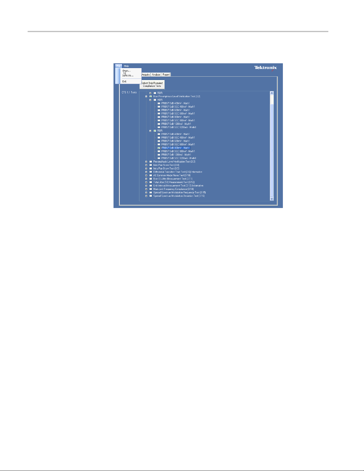
Select Tab
The Select tab l
Figure 3: The Select tab
ists the available tests.
You can expand the tree of tests to select tests for a specific type of signal (such as
PRBS7 signal of 400 mV amplitude and with 3.5 dB of pre-emphasis). You can
or deselect all the tests of a branch by selecting or clearing the higher-level
select
check box. When selected tests require additional tests that are not already
selected, the application automatically selects the required tests.
The available selections can include tests that are not required for compliance.
Click the Select Only Required Compliance Tests button to limit the
measurement set to just those tests required to meet compliance requirements.
To save a test selection, select File > Save As. To recall a previously saved test
selection, select File > Open.
4 DPOD SPT DisplayPort Software
Page 11

About the Application Software
Acquire Tab
NOTE. The oscil
thatwasusedtocreatethesavedtest. Forexample,testssavedusingTCASMA
connectors cannot be run on an oscilloscope that is using differential probes.
Recalling a file with this sort of mismatch results in no tests being available on
the Select tab.
The tree of tests is built based on the supported signal types selected in the
Configure tab. Any change in the Configure tab settings resets the test selection
settings.
Stored waveforms and other data from a test session can fill several GB of hard
disk space. You may need to move data to a higher-capacity storage area when
running m
The Acquire tab lists the signals that will be acquire d, based on the test selections
in the Se
pre-emphasis level, amplitude value, SSC, and source oscilloscope channel.
The Acq
saved as oscilloscope reference waveforms in the folder specified by the DUT
name (“c:\Program Files\Tektronix\DPODSPTAAA\_Display_Port” where AAA is
thenameenteredintheDUTNamefield of the Configure tab).
lect tab. The tab displays information such as type of pattern, data rate,
uire button starts the signal acquisition process. The acquired signals are
loscope must have the same hardware and probe configuration
any test sessions.
Figure 4: The Acquire tab
DPODSPT DisplayPort Software 5
Page 12

About the Application Software
NOTE. Some of th
to be acquired does not show duplication of signals when used for multiple
measurements.
When you start the acquisition by clicking the Acquire button, a pop-up message
box, as shown in figure 5, displays the signal being acquired. Attributes of the
signal to be
There are four buttons in the Acquire tab:
Abort Tests. Click this button to abort the entire test session. No acquisition
takes place.
Skip. Click this button to stop acquiring the current signal and move (skip) to the
next signal type in the list. Measurements that depend on the skipped signal type
will not
Check Signal. Click this button to manually validate the signal (show the required
and actual attributes of the signal acquired). If they do not match, the application
displays an alert message.
be performed.
e signals can support multiple tests. The list of signals
acquired are displayed.
Figure 5: Acquire tab, Check Signal results
Use S ignal. Click this button to acquire and use the acquired signal for the test. In
this case, signal validation takes place by default. If there is a mismatch between
the required and acquired signal attributes, a warning screen allows you to change
the DUT output signal or use the existing signal.
NOTE. Validation of the signal acquired against what is required happens by
default for all the acquisitions. The Check Signal button is provided to manually
perform and display a signal validation.
6 DPOD SPT DisplayPort Software
Page 13

About the Application Software
Acquire Tab (if
DP-AUX Control)
using
Figure 6: Acquire tab, DP-AUX connected
When the Tektronix DP-AUX DisplayPort AUX Control is used, the Acquire tab
displays AU
that do not pass the signal quick check:
Use Signal
Prompt User: Prompts you with each failed signal
Discard Signal & Continue: Discards the signal and continues without
prompting (continues with accepted signals)
There is also a Silicon selection, the contents of which are determined by the
connected DP-AUX Control board. DisplayPort Tx reads which Silicon the
DP-AUX
list.
X Control Options. You can select which actions occur with signals
& Continue: Uses the signal and continues without prompting
Control board supports and that list is used to populate this drop down
Figure 7: DUT Configuration dialog box
The DUT Configuration dialog box also changes when a DP-AUX Control is
being used. If you chose Prompt the user from the Aux Control Options area
n the Acquire tab, and the DUT Configuration dialog is displayed, then you can
o
change your previous selection by checking the box for Apply to All Subsequent
Signals and selecting either Use & Continue or Discard & Continue buttons.
DPODSPT DisplayPort Software 7
Page 14

About the Application Software
Acquire Tab (if
previously-stored
waveforms)
using
Figure 8: Stored Files drop-down menu
IfyouselectedthedatasourceasStoredFilesratherthanConnecttoDUTin
the Configure tab, the Acquire tab shows a different set of choices. Instead of
the Acquire button, the Acquire tab displays two buttons: Load Individual Files
and Load A
ll From Directory.
Figure 9: Load Stored Files opening screen
Click the Load Individual Files button to open a pop-up window that shows a
description of the first signal type needed. Press the Read Waveform button and
then navigate to and select the fi le to load. The waveform file must meet the signal
conditions for the listed signal type.
8 DPOD SPT DisplayPort Software
Page 15

About the Application Software
If you are loadi
the DPODSPT application, the file names indicate the signal type and
settings used to create that file. For example, a saved file could be named
PRBS7_HBR_400mV_0dB.wfm. If you manually name a file name for saved
waveform data, use a file naming convention that clearly describes all of the
waveform parameters.
ng waveform files that were automatically saved from
Figure 10: Load Individual Files navigation screen
DPODSPT DisplayPort Software 9
Page 16

About the Application Software
If a large colle
Directory button can help automate and speed testing. Clicking this button opens
a dialog box with which you navigate to and select the folder where a collection
of waveform files are stored. The application then attempts to perform all the
selected tests using the waveform files in selected folder.
ction of waveform files have been saved, the Load All From
Figure 11: Load All From Directory dialog box
10 DPODSPT DisplayPort Software
Page 17

About the Application Software
Analyze Tab
The applicatio
acquiring signals (as set in the Acquire tab). This tab displays the sequence of
tests to automatically execute after all the necessary signals are acquired, as well
as a test progress indicator. You can automatically save the test sequence steps
to a log file by checking the Verbose Logging /Reporting check box on the
Configure tab.
n automatically opens the Analyze tab when it has completed
Figure 12: Analyze screen showing test progress indicator
NOTE. Tests are automatically executed at the end of the acquisition process. The
utton lets you rerun the tests with already acquired signals.
Run b
DPODSPT DisplayPort Software 11
Page 18

About the Application Software
Report Tab
The applicatio
signals in the Analyze tab. The Report tab displays the results of the tests
executed. The report data is saved in the data file folder associated with this test
session, as both a PDF and .csv format file.
n automatically opens the Report tab when it has completed testing
Figure 13: The Report tab.
The PDF report includes:
and time of the test session (from the system clock)
Date
The version of the DPODSPT Software
The version of the Compliance test specification (CTS) to which this test
session conforms
Device / DUT name and User comments (as entered in the Select Tab)
Compliance test summary
Detailed test summary
Individual test results with necessary graphic(s) / plot(s)
12 DPODSPT DisplayPort Software
Page 19

Compliance Testing
NOTE. The PDF re
tests are saved in the folder specified by the DUT name (c:\Program
Files\TekApplications\DPODSPT\DUT-Name-Field-Text).
Compliance Testing
1. Set up the application, test equipment, and DUT. (See page 1, Instrument
Connection.) (See page 1, Prerequisites.)
2. Start the DPODSPT application (from the Analyze menu in the oscilloscope
main control menu). The application will automatically detect what is
connected to each oscilloscope input channel - either a differential probe or
TCA-SMA adapter. The “Lane Assignment” section of the Configure tab will
show the input configuration.
3. If using TCA-SMA connections, configure the lane assignment for the
oscilloscope channels.
4. In the Configure tab:
port, .csv report, log file and waveforms used for the
Set the parameters for the DUT signals.
Enter the DUT name. The DUT name is assigned to the folder where all
the waveforms (used for the tests), log file, and finaltestreport(PDF
file) are saved.
Enter a comment in the User Comment field (optional). The comment
text is added to the PDF test report.
Select the Verbose Logging/Reporting check box to automatically log
the sequence of operation/test execution.
5. In the Select tab:
Select the tests to run.
Optionally save this test setup or recall a saved setup.
6. In the Acquire tab:
Click the Acquire button to start acquiring signal(s). The signals are
validated against the signals required for running the specified tests.
Click the Use Signal buttonontheDUT Configuration dialog box when
you find the signal acquired is correct.
If the s
DUT settings and connections, and validate the new signal by clicking
the Check Signal button. Once you have the correct signal, click the
Use Signal button to continue to the next acquisition. If signal problems
cannot be resolved, click the Skip button.
ignal acquired is not what is required for the test, recheck your
DPODSPT DisplayPort Software 13
Page 20

Oscilloscope Probe or Cable Calibration
Oscillos
Keep changing t
test signals as prompted by the Acquisition Status dialog box.
If you are usin
what the software should do with "check signal" failures.
7. Once all the
running the tests. If tests do not automatically start running, click the Run
button in the Analyze tab. Test execution progress is shown in a status
window. Once the tests are executed, the report is shown in the Report tab.
The waveforms and report are stored in the specified folder.
signals are acquired, the application will automatically start
he DUT settings and connections to acquire appropriate
g the optional Tektronix DP-AUX Control device, specify
cope Probe or Cable Calibration
Before b
run a signal path compensation (SPC) operation, and deskew the test cables or
probes you are using for the DUT test. Signal Path Compensation compensates
the signal pathways for gain and offset errors. Cable deskew compensates for
timing differences between any two cables or probes. This section includes the
procedure for running a SPC and deskewing the cables/probes.
The DSA/DPO70000 series oscilloscope must b e calibrated (SPC and deskew)
manually after a minimum 20-minute warm-up period or whenever a new
meas
eginning any test or data acquisition, you must warm up the oscilloscope,
urement session is going to begin.
Signal Path Compensation
These calibrations are not permanent. It is recommended that you perform a
nal path compensation once a week and whenever the ambient temperature of
sig
the oscilloscope has changed by more than 5 °C. It is recommended that you
perform a cable deskew before starting any new measurement session using the
oscilloscope and cables.
Use the following procedure to run the signal path compensation (SPC) utility:
isconnect all input cables to the oscilloscope channels.
1.D
2. Install Tektronix TCA-SMA (or TCA-292MM) input adapters in all four
channels, and make sure that nothing is connected to the SMA inputs. The
adapters prevent transient voltages from leaking into the input amplifiers
and analog to digital converters that could adversely affect the quality of
the calibration routine.
3. Select Utilities > Instrument Calibration in the DPO/DSA70000 application.
4. Click the Calibrate button. It takes about 10 minutes to get the SPC
calibration result. The final status should be Pass.
14 DPODSPT DisplayPort Software
Page 21

Oscilloscope Probe or Cable Calibration
Cable Deskewing
Use the followi
cables and input channels. Perform this procedure on each pair of cables you
will use for DUT testing.
1. Connect TCA-SMA TekConnect adapters to all four channels of the
oscilloscope.
2. Press the Default Setup front-panel button.
3. Connect the
torque-wrench to tighten the connections to 7-10 in lbs.
4. Select the
5. Deselect channels Ch3 and Ch4 (verify that they are not active/selected).
6. Connect a power splitter to the Fast Edge output connector.
ng procedure to compensate for timing differences between SMA
SMA c ables to channels Ch1, Ch2, Ch3 and Ch4. Use a
Ch1 and Ch2 front panel channel button to activate those channels.
re 14: Cable deskew connections
Figu
7. Con
8. Press the Autoset front-panel button. Click OK on the confirmation window.
9. Adjust the Vertical Scale (increase it without any clipping) and Position
10. Select Horiz/Acq > Horizontal/Acquisition Setup from the oscilloscope
11. Click the Acquisition tab.
12. Select Ave r ag e acquisition mode.
13. Set the #ofWfmsfield to 16.
nect the cables from Ch1 and Ch2 to the power splitter outputs.
controls for each channel so that the signals overlap and are centered on the
splay.
di
enu bar.
m
DPODSPT DisplayPort Software 15
Page 22

Oscilloscope Probe or Cable Calibration
Figure 15: S
14. Adjust the
of the display.
15. Adjust th
channel delays are clearly visible. (See Figure 16.)
Figure 16: Visible cable skew
16. Adjust the horizontal Position again so that the first rising edge is exactly
at the center of the display. The short length (electrical length) cable is
connected to this channel.
etting Average mode
Horizontal Position so that a rising edge is triggered at the center
e horizontal Scale (Lower time/pt) so that the differences in the
17. Select Vertical > Deskew from the oscilloscope menu to open the Deskew
control window.
18. Select Ch2.
19. Adjust the deskew time for Ch2 so that its signal aligns with Ch1.
16 DPODSPT DisplayPort Software
Page 23

Oscilloscope Probe or Cable Calibration
Figure 17: Cable skew adjusted
20. Remove the cable attached to Ch2 from the power splitter. Keep the other
end of the cable attached to the oscilloscope input.
21. Repeat steps 3 to 20, connecting the cable from Ch3 to the deskew attachment.
Make sure to deselect Ch2 and select Ch3.
22. Repeat steps 3 to 20, connecting the cable from Ch4 to the deskew attachment.
Make sure to deselect Ch3 and select Ch4.
23. The deskew procedure is complete when Ch2, Ch3, and Ch4 have all been
deskewed to Ch1. Take care to leave the cable and oscilloscope connections
undisturbed for the duration of testing on the DisplayPort source device.
NOTE. If you are using differential probes instead of direct SMA cable connections
to the oscilloscope, perform the procedure with the cables connected to the +
put side of each probe.
in
DPODSPT DisplayPort Software 17
 Loading...