

Page 1

x
DPO7000 Series, DPO70000/B, and DSA70000/B Series
Digital Phosphor Oscilloscopes
ZZZ
Quick Start User Manual
*P071259700*
071-2597-00
Page 2

Page 3

xx
DPO7000 Series, DPO70000/B, and DSA70000/B Series
Digital Phosphor Oscilloscopes
ZZZ
Quick Start User Manual
www.tektronix.com
071-2597-00
Page 4

Copyright © Tektronix. All rights reserved. Licensed software products are owned by Tektronix or its subsidiaries or suppliers, and are
protected by na
tional copyright laws and international treaty provisions.
Tektronix pro
previously published material. Specifications and price change privileges reserved.
TEKTRONIX and TEK are registered trademarks of Tektronix, Inc.
FastFrame, OpenChoice, iView, Pinpoint, RT-Eye, MyScope, TekLink, TekVPI, and MultiView Zoom are trademarks of Tektronix, Inc.
ducts are covered by U.S. and foreign patents, issued and pending. Information in this publication supersedes that in all
Contacting Tektronix
Tektronix, Inc.
14200 SW Karl Braun Drive
P.O. Box 500
Beaverton, OR 97077
USA
For product information, sales, service, and technical support:
In North America, call 1-800-833-9200.
Worldwide, visit www.tektronix.com to find contacts in your area.
Page 5

Warranty
Tektronix warrants that this product will be free from defects in materials and workmanship for a period of one (1) year from the date of
shipment. If any such product proves defective during this warranty period, Tektronix, at its option, either will repair the defective
product without charge for parts and labor, or will provide a replacement in exchange for the defective product. Parts, m odules and
replacement products used by Tektronix for warranty work may be new or reconditioned to like new performance. All replaced
parts, modules and products become the property of Tektronix.
In order to obtain service under this warranty, Customer must notify Tektronix of the defect before the expiration of the warranty period
and make suitable arrangements for the performance of service. Customer shall be responsible for packaging and shipping the
defective product to the service center designated by Tektronix, with shipping charges prepaid. Tektronix shall pay for the return of the
product to Customer if the shipment is to a location within the country in which the Tektronix service c enter is located. Customer shall
be responsible for paying all shipping charges, duties, taxes, and any other charges for products returned to any other locations.
This warranty shall not apply to any defect, failure or damage caused by improper use or improper or inadequate maintenance and
care. Tektronix shall not be obligated to furnish service under this warranty a) to repair damage resulting from a ttempts by personnel
other than Tektronix representatives to install, repair or service the product; b) to repair damage resulting from improper use or
connection to incompatible equipment; c) to repair any damage or malfunction caused by the use of non-Tektronix supplies; or
d) to service a product that has been modified or integrated with other products when the effect of such modification or integration
increases the time or difficulty of servicing the product.
THIS WARRANTY IS GIVEN BY TEKTRONIX WITH RESPECT TO THE PRODUCT IN LIEU OF ANY OTHER WARRANTIES,
EXPRESS OR IMPLIED. TEKTRONIX AND ITS VENDORS DISCLAIM ANY IMPLIED WARRANTIES OF MERCHANTABILITY OR
FITNESS FOR A PARTICULAR PURPOSE. TEKTRONIX’ RESPONSIBILITY TO REPAIR O R REPLACE DEFECTIVE PRODUCTS
IS THE SOLE AND E XCLU S IVE REMEDY PROVIDED TO THE CUSTOMER FOR BREACH OF THIS WARRANTY. TEKTRONIX
AND ITS VENDORS WILL NOT BE LIABLE FOR ANY INDIRECT, SPECIAL, INCIDENTAL, OR CONSEQUENTIAL DAMAGES
IRRESPECTIVE OF WHETHER TEKTRONIX OR THE VENDOR HAS ADVANCE NOTICE OF THE POSSIBILITY OF SUCH
DAMAGES.
[W2 – 15AUG04]
Page 6

Page 7

Table of Contents
General Safety Summary ...... . . . . . .... . . . . . . .... . . . . . . ... . . . . . . ..... . . . . . .... . . . . . . .... . . . . . . ... . . . . . . ..... . . . . . .... . . . . . . .... . . . . .. v
Compliance Information.............................................................................................................. vii
EMC Compliance................................................................................................................ vii
Safety Compliance............................................................................................................... ix
Environmental Considerations................................................................................................... xi
Preface................................................................................................................................ xii
Key Features .................................................................................................................... xii
Documentation ................................................................................................................. xiii
Conventions Used in this Manual . . . . .... . . . . . . .... . . . . . . .... . . . . . . .... . . . . . . .... . . . . . . .... . . . . . . .... . . . . . . ..... . . . . . . ... . . . . . xiv
Install Your Instrument................................................................................................................. 1
Standard Accessories. . . ..... . . . . . . .... . . . . . . ... . . . . . . ..... . . . . . . .... . . . . . . ... . . . . . . ..... . . . . . . .... . . . . . . .... . . . . . . .... . . . . . . .... 1
Operating Requirements...... . . . . . . ..... . . . . . . .... . . . . . . ... . . . . . . ..... . . . . . . .... . . . . . . .... . . . . . . .... . . . . . . .... . . . . . . .... . . . . . . .. 2
Preventing ESD .................................................................................................................. 4
Powering Onthe Instrument..................................................................................................... 5
Powering Off the Instrument..................................................................................................... 7
Removing the Power............................................................................................................. 7
Connecting to a Network... . . . . . . .... . . . . . . .... . . . . . . .... . . . . . .... . . . . . . .... . . . . . . .... . . . . . . .... . . . . . . ... . . . . . . ..... . . . . . .... . . . . 8
Adding a Second Monitor........................................................................................................ 9
Creating Operating System Restore CD-ROMs ............................................................................... 12
Getting Acquainted with Your Instrument .... . . . . . ..... . . . . . . ... . . . . . . .... . . . . . . .... . . . . . ..... . . . . . . .... . . . . . .... . . . . . . .... . . . . . . .... 13
Front Panel ... . . . . . . . .... . . . . . . ..... . . . . . . .... . . . . . . ..... . . . . . . .... . . . . . . ..... . . . . . . .... . . . . . . ..... . . . . . . .... . . . . . . . .... . . . . . . . ..13
Side and Rear Panels... . . . . . . ..... . . . . . . .... . . . . . . ..... . . . . . . . .... . . . . . . . .... . . . . . . ..... . . . . . . .... . . . . . . ..... . . . . . . . .... . . . . . . . 14
Interface and Display ........................................................................................................... 16
Control Panel ... . . . . . . ..... . . . . . . .... . . . . . . .... . . . . . . .... . . . . . . . ... . . . . . . . .... . . . . . . .... . . . . . . ..... . . . . . . .... . . . . . . ..... . . . . . . ...18
Accessing Online Help.......................................................................................................... 19
Accessing Menus and Control Windows . . . . ..... . . . . . . .... . . . . . . .... . . . . . . .... . . . . . . .... . . . . . . ..... . . . . . . .... . . . . . . ... . . . . . . . . 20
Inspect Your Instrument .............................................................................................................. 21
Verify Internal Diagnostics Pass . . . . . .... . . . . . .... . . . . . .... . . . . . . ... . . . . . . ... . . . . . . ... . . . . . . ... . . . . . . .... . . . . . .... . . . . . .... . . . . . 21
Acquisition ............................................................................................................................ 23
Signal P ath Compensation . . . . . .... . . . . . .... . . . . . . .... . . . . . . .... . . . . . . .... . . . . . .... . . . . . . .... . . . . . . .... . . . . . . .... . . . . . . ... . . . . . 23
ing Up Signal Input . . .... . . . . . . ... . . . . . . ... . . . . . . .... . . . . . .... . . . . . . ... . . . . . . .... . . . . . ..... . . . . . .... . . . . . . ... . . . . . . .... . . . . . 25
Sett
Using Default Setup............................................................................................................. 26
Using Autoset ................................................................................................................... 27
Probe Compensation, Calibration, and Deskew . . ..... . . . . . . ..... . . . . . . . .... . . . . . . ..... . . . . . . . ..... . . . . . . .... . . . . . . . . .... . . . . . 28
Acquisition Concepts............................................................................................................ 28
How the Acquisition Modes Work .. . . . . . . ... . . . . . . .... . . . . . ..... . . . . . .... . . . . . . ... . . . . . . .... . . . . . . ... . . . . . . .... . . . . . ..... . . . . . . 31
Changing the Acquisition Mode . . . . ..... . . . . . .... . . . . . . .... . . . . . . ... . . . . . . ..... . . . . . . ... . . . . . . .... . . . . . . .... . . . . . ..... . . . . . . ... 32
Starting and Stopping an Acquisition. . . . . . . .... . . . . . .... . . . . . . .... . . . . . ..... . . . . . . ... . . . . . . .... . . . . . . ... . . . . . . .... . . . . . ..... . . . 33
Selecting theHorizontal Mode.................................................................................................. 33
Using FastAcq................................................................................................................... 35
Using DSP Enhanced B andwidth . . .... . . . . . ..... . . . . . . .... . . . . . . ... . . . . . . ..... . . . . . . ... . . . . . . .... . . . . . . ..... . . . . . .... . . . . . . ... 36
Using Roll Mode................................................................................................................. 38
Table of Content
s
DPO7000 Series and DPO/DSA70000/B Series Quick Start User Manual i
Page 8

Table of Content
Pinpoint Triggers.. . . . . . .... . . . . . .... . . . . . ... . . . . . . ... . . . . . . ... . . . . . .... . . . . . .... . . . . . .... . . . . .... . . . . . .... . . . . . .... . . . . . ... . . . . ....... 47
Display a Waveform .................................................................................................................. 58
Analyzing Waveforms . . . . . ..... . . . . . . .... . . . . . . ..... . . . . . . ... . . . . . . .... . . . . . . ..... . . . . . . .... . . . . . . .... . . . . . . . ... . . . . . . .... . . . . . . ..... 80
MyScope ............................................................................................................................ 104
Saving and Recalling Information.................................................................................................. 110
s
Using FastFrame Mode......................................................................................................... 39
Using FastFrame Frame Finder . . . . . . .... . . . . . . ..... . . . . . . .... . . . . . . ..... . . . . . . .... . . . . . . ..... . . . . . . .... . . . . . . .... . . . . . . .... . . . 42
Using TekLink and MultiScope Trigger .. . . . . . . .... . . . . . .... . . . . . . .... . . . . . ..... . . . . . .... . . . . . . .... . . . . . .... . . . . . . .... . . . . . ..... 43
Triggering Concepts............................................................................................................. 47
Choosing a Trigger Type. . . ..... . . . . . . .... . . . . . .... . . . . . . ..... . . . . . . .... . . . . . . ... . . . . . . ..... . . . . . . .... . . . . . . .... . . . . . . .... . . . . . . 49
Pinpoint Trigger Selections . . . . . . .... . . . . . . .... . . . . . . ... . . . . . . .... . . . . . . ... . . . . . . ..... . . . . . .... . . . . . . .... . . . . . .... . . . . . . .... . . . . 50
Checking Trigger Status . . . ... . . . . . . ..... . . . . . .... . . . . . . .... . . . . . .... . . . . . . .... . . . . . ..... . . . . . . ... . . . . . . .... . . . . . . ... . . . . . . .... . 52
Using A (Main) and B (Delayed) Triggers . . ... . . . . . . .... . . . . . . ..... . . . . . .... . . . . . . .... . . . . . . .... . . . . . . .... . . . . . . .... . . . . . . ... . . 53
Sending E-mail on Trigger . . . . .... . . . . . . .... . . . . . . ... . . . . . . .... . . . . . . ... . . . . . . ..... . . . . . .... . . . . . . .... . . . . . .... . . . . . . .... . . . . . .. 56
Using Horizontal Delay.......................................................................................................... 57
Setting the Display Style ........................................................................................................ 58
Setting the Display Persistence ................................................................................................ 59
Setting the Display Format...................................................................................................... 60
Selecting theWaveform Interpolation .......................................................................................... 61
Adding Screen Text .... . . . . . .... . . . . . . .... . . . . . .... . . . . . . .... . . . . . ..... . . . . . .... . . . . . . .... . . . . . .... . . . . . . .... . . . . . ..... . . . . . . ... 61
Setting the Graticule Style ...................................................................................................... 63
Setting the Trigger Level Marker . . ... . . . . . . .... . . . . . . ..... . . . . . . .... . . . . . . .... . . . . . . .... . . . . . . .... . . . . . . ..... . . . . . . .... . . . . . . .. 64
Displaying the Date and Time .................................................................................................. 64
Using the Color Palettes ........................................................................................................ 65
Setting the Reference Colors ................................................................................................... 66
Setting Math Colors ............................................................................................................. 66
Using MultiView Zoom .......................................................................................................... 66
Zooming inMultiple Areas ...................................................................................................... 68
Lock and Scroll Zoomed Waveforms........................................................................................... 69
Hide Waveforms in the Zoomed Window . . . ..... . . . . . . .... . . . . . . . ..... . . . . . . ..... . . . . . . .... . . . . . . . .... . . . . . . . ..... . . . . . . .... . . 71
Searching and Marking Waveforms . . . . . .... . . . . . . .... . . . . . . .... . . . . . . .... . . . . . . ..... . . . . . . .... . . . . . . ..... . . . . . . .... . . . . . . ..... 72
Taking Automatic Measurements............................................................................................... 80
Automated Measurement Selections........................................................................................... 82
Customizing an Automatic Measurement...................................................................................... 84
Taking CursorMeasurements .................................................................................................. 88
Setting Up a Histogram ......................................................................................................... 91
Using Math Waveforms......................................................................................................... 92
Using Spectral Analysis . . . .... . . . . . . ... . . . . . . ... . . . . . . .... . . . . . .... . . . . . ..... . . . . . .... . . . . . .... . . . . . . ... . . . . . . ... . . . . . . .... . . . . . 95
Using Mask Testing ............................................................................................................. 98
Using Limit Testing............................................................................................................ 102
Creating a N ew MyScope Control Window ... . . . . . .... . . . . . . .... . . . . . . ... . . . . . . ..... . . . . . . ... . . . . . . .... . . . . . . ... . . . . . . ..... . 104
Using MyScope Control Windows . . . . . . . .... . . . . . . .... . . . . . . .... . . . . . . .... . . . . . . ..... . . . . . . .... . . . . . . ... . . . . . . . .... . . . . . . .... 108
Saving Screen Captures...................................................................................................... 110
Saving Waveforms ............................................................................................................. 111
Recalling Waveforms ......................................................................................................... 113
ii DPO7000 Series and DPO /DS A70000/B Series Quick Start User Manual
Page 9

Table of Content
Saving Instrument Setups .................................................................................................... 114
Recalling Inst
Saving Measurements........................................................................................................ 116
Copying Your Results to the Clipboard.. . . . . . . .... . . . . . . .... . . . . . . .... . . . . . . .... . . . . . . ..... . . . . . . .... . . . . . . ..... . . . . . . .... . . . 117
Printing a H ar
Run Application Software ..........................................................................................................121
Application Examples............................................................................................................... 123
Capturing In
Using the Extended Desktop and OpenChoice Architecture for Efficient Documentation ................................. 126
Triggering on Buses.. . . . . . . ..... . . . . . . ... . . . . . . .... . . . . . . .... . . . . . ..... . . . . . . ... . . . . . . .... . . . . . . .... . . . . . ..... . . . . . . ... . . . . . . . 128
Triggering
Setting Up E-mail on Event ................................................................................................... 131
Correlating Data Between a Tektronix Oscilloscope and Logic Analyzer . . . . . . .... . . . . . . . ... . . . . . . .... . . . . . . ..... . . . . . . .... 133
Verifying
Cleaning . . . . .... . . . . . . .... . . . . . ..... . . . . . .... . . . . . . .... . . . . . .... . . . . . . .... . . . . . ..... . . . . . . ... . . . . . . .... . . . . . . ... . . . . . . .... . . . . . 137
Index
rument Setups.................................................................................................. 115
d Copy.......................................................................................................... 119
termittent Anomalies.... . . . . . . .... . . . . . . .... . . . . . .... . . . . . . .... . . . . . . .... . . . . . . .... . . . . . .... . . . . . . .... . . . . . . .... . 123
on a Video Signal. .... . . . . . . ..... . . . . . . .... . . . . . . ..... . . . . . . .... . . . . . . .... . . . . . . . ... . . . . . . . ... . . . . . . . .... . . . . . . .... 129
Performance Using Limit Test ...................................................................................... 134
s
DPO7000 Series and DPO/DSA70000/B Series Quick Start User Manual iii
Page 10

Table of Content
s
iv DPO7000 Series and DPO/DSA70000/B Series Quick Start User Manual
Page 11

General Safety S
ummary
General Safet
Review the following safety precautions to avoid injury and prevent damage to this product or any products connected to it.
To avoid potential hazards, use this product only as specified.
Only qualified personnel should perform service procedures.
While using this product, you may need to access other parts of a larger system. Read the safety sections of the other
component manuals for warnings and cautions related to operating the system.
To Avoid Fire or Personal Injury
Use Proper Power Cord. Use only the power cord specified for this product and certified for the country of use.
Connect and Disconnect Properly. Do not connect or d isconnect probes or test leads while they are c onnected
to a voltag
Ground th
shock, the grounding conductor must be connected to earth ground. Before making connections to the input or output
terminals of the product, ensure that the product is properly grounded.
Observe All Terminal Ratings. To avoid fire or shock hazard, observe all ratings and markings on the product. Consult
the prod
The inpu
e source.
e Product.
uct manual for further ratings information before making connections to the product.
ts are not rated for connection to mains or Category II, III, or IV circuits.
y Summary
This product is grounded through the grounding conductor of the power cord. To avoid electric
Connect
Power D
must remain accessible to the user at all times.
the probe reference lead to earth ground only.
isconnect.
The power cord disconnects the product from the power source. Do not block the power cord; it
Do Not Operate Without Covers. Do not operate this product with covers or panels removed.
Do Not Operate With Suspected Failures. If you suspect that there is damage to this product, have it i nspected by
qualified service personnel.
Avoid Exposed Circuitry. Do not touch exposed connections and components when power is present.
Do Not Operate in Wet/Damp Conditions.
Do Not Operate in an Explosive Atmosphere.
Keep Product Surfaces Clean and Dry.
Provide Proper Ventilation.
per ventilation.
pro
Refer to the manual’s installation instructions for details on installing the product so it has
DPO7000 Series and DPO/DSA70000/B Series Quick Start User Manual v
Page 12

General Safety S
TermsinthisManual
These terms may appear in this manual:
WARNING. Warning statements identify conditions or practices that could result in injury or loss of life.
CAUTION. Caution statements identify conditions or practices that could result in damage to this product or other property.
Symbols and Terms on the Product
These terms may appear on the product:
DANGER indicates an injury hazard immediately accessible as you read the marking.
WARNING indicates an injury hazard not immediately accessible as you read the marking.
CAUTION indicates a hazard to property including the product.
The following symbol(s) may appear on the product:
ummary
vi DPO7000 Series and DPO/DSA70000/B Series Quick Start User Manual
Page 13

Compliance Info
rmation
Compliance In
This section lists the EMC (electromagnetic compliance), safety, and environmental standards with which the instrument
complies.
EMC Compliance
EC Declarati
Meets intent of Directive 2004/108/EC for E lectromagnetic Compatibility. Compliance was demonstrated to the following
specifications as listed in the Official Journal of the European Communities:
EN 61326-1:2006, EN 61326-2-1:2006. EMC requirements for electrical equipment for measurement, control, and
laborator
CISPR 11:2
IEC 61000
IEC 61000
IEC 61000
IEC 6100
IEC 6100
IEC 6100
on of Conformity – EMC
1,2,3
yuse.
003. Radiated and conducted emissions, Group 1, Class A
-4-2:2001. Electrostatic discharge immunity
-4-3:2002. RF electromagnetic field immunity
-4-4:2004. Electrical fast transient/burst immunity
0-4-5:2001. Power line surge immunity
0-4-6:2003. Conducted RF immunity
0-4-11:2004. Voltage dips and interruptions immunity
formation
4
4
5
EN 61000-3-2:2006. AC power line harmonic emissions
EN 6100
0-3-3:1995.
Voltage changes, fluctuations, and flicker
European Contact.
Tektronix UK, Ltd.
Western Peninsula
Western Road
Bracknell, RG12 1RF
United Kingdom
1
2
3
4
5
product is intended for use in nonresidential areas only. Use in residential areas may cause electromagnetic interference.
This
Emissions which exceed the levels required by this standard may occur when this equipment is connected to a test object.
If interconnect cables are used, they must be low–EMI shielded cables such as the following Tektronix part numbers or their
equivalents: 012-0991-01, 012-0991-02 or 012-0991-03 GPIB Cable; 012-1213-00 (or CA part number 0294-9) RS-232 Cable;
1214–00 Centronics Cable; or LCOM part number CTL3VGAMM-5 VGA Cable. Use an 012-0482-00 cable for the Ref Out connector.
012-
The performance criterion for when the oscilloscope is subjected to the continuously present electromagnetic phenomenon:
/division to 1 V/division: ≤0.4 division waveform displacement or ≤0.8 division increase in peak–to–peak noise Performance
10 mV
criterion for when the oscilloscope is subjected to transient electromagnetic phenomenon: Temporary, self–recoverable degradation
or loss of performance is allowed, but no change of actual operating state or loss of stored data is allowed.
Performance Criterion C applied at the 70%/25 cycle Voltage-Dip and the 0%/250 cycle Voltage-Interruption test levels
(IEC 61000-4-11). If the instrument powers down upon a voltage dip or interruption it will take longer than ten seconds to reboot.
DPO7000 Series and DPO/DSA70000/B Series Quick Start User Manual vii
Page 14

Compliance Info
Australia / New Zealand Declaration of Conformity – E MC
Complies with the EMC provision of the Radioc ommunications Act per the following standard:
CISPR 11:2003. Radiated and Conducted Emissions, Group 1, Class A, in accordance with EN 61326-1:2006 and
EN 61326-2-1:2006.
rmation
viii DPO7000 Series and DPO /DS A70000/B Series Quick Start User Manual
Page 15

Safety Compliance
EC Declaration of Conformity – Low Voltage
Compliance was demonstrated to the following specification as listed in the Official Journal of the European Communities:
Low Voltage Directive 2006/95/EC.
EN 61010-1: 2001. Safety requirements for electrical equipment for measurement control and laboratory use.
Compliance Info
rmation
U.S. Nation
UL 61010-1:2004, 2ndEdition. Standard for electrical measuring and test equipment.
ally Recognized Testing Laboratory Listing
Canadian Certification
CAN/CSAlaboratory use. Part 1.
C22.2 No. 61010-1:2004. Safety requirements for electrical equipment for measurement, control, and
Additional Compliances
IEC 61010-1: 2001. Safety requirements for electrical equipment for measurement, control, and laboratory use.
Equipment Type
Test and measuring equipment.
y Class
Safet
Class 1 – grounded product.
Pollution Degree Description
asure of the contaminants that could occur in the environ ment around and within a p roduct. Typically the internal
Ame
environment inside a product is considered to be the same as the external. Products should be used only in the environment
for which they are rated.
Pollution Degree 1. No pollution or only dry, nonconductive pollution occurs. Products in this category are generally
capsulated, hermetically sealed, or located in clean rooms.
en
llution Degree 2. Normally only dry, nonconductive polluti on occurs. Occasionally a temporary conductivity that is
Po
caused by condensation must be expected. This location is a typical office/home environment. Temporary condensation
occurs only when the product is out of service.
Pollution Degree 3. Conductive pollution, or dry, nonconductive pollution that becomes conductive due to condensation.
hese are sheltered locations where neither temperature nor humidity is controlled. The area is protected from direct
T
sunshine, rain, or direct wind.
Pollution Degree 4. Pollution that generates persistent conductivity through conductive dust, rain, or snow. Typical
outdoor locations.
DPO7000 Series and DPO/DSA70000/B Series Quick Start User Manual ix
Page 16

Compliance Info
Pollution Degree
Pollution Degree 2 (as defined in IEC 61010-1). Note: Rated for indoor use only.
Installation (Overvoltage) Category Descriptions
Terminals on this product may have different installation (overvoltage) category designations. The installation categories are:
Measurement Category IV. For measurements performed at the source of low-voltage installation.
Measurement Category III. For measurements performed in the building installation.
Measurement Category II. For measurements performed on circuits directly connected to the low-voltage installation.
Measurement Category I. For measurements performed on circuits not directly connected to MAINS.
rmation
Overvolta
Mains: Overvoltage Category II
Measurement inputs: Overvoltage Category I
(As defined in IEC 61010-1)
ge Category
x DPO7000 Series and DPO/DSA70000/B Series Quick Start User Manual
Page 17

Environmental Considerations
This section provides information about the environmental impact of the product.
Product End-of-Life Handling
Observe the following guidelines when recycling an instrument or component:
Equipment Recycling. Production of this equipment required the extraction and use of natural resources. The
equipment may contain substances that could be harmful to the environment or human health if improperly handled at the
product’s end of life. In order to avoid release of such substances into the environment and to reduce the use of natural
resources, we encourage you to recycle this product in an appropriate system that will ensure that most of the materials are
reused or recycled appropriately.
This symbol indicates that this product c omplies w ith the applicable European Union requirements according
to Directives 2002/96/EC and 2006/66/EC on waste electrical and electronic equipment (WEEE) and
batteries. For information about recycling options, check the Support/Service section of the Tektronix Web
site (www.tektronix.com).
Compliance Info
rmation
Mercury N
to environmental considerations. Please contact your local authorities or, within the United States, refer to the E-cycling
Central Web page (www.eiae.org) for disposal or recycling information.
otification.
This product uses an LCD backlight lamp that contains mercury. Disposal may be regulated due
Perchlorate Materials. This product contains one or more type CR lithium batteries. According to the state
of California, CR lithium batteries are classified as perchlorate materials and require special handling. See
www.dtsc.ca.gov/hazardouswaste/perchlorate for additional information.
Restriction of Hazardous Substances
roduct has been classified as Monitoring and Control equipment, and is outside the scope of the 2002/95/EC RoHS
This p
Directive.
DPO7000 Series and DPO/DSA70000/B Series Quick Start User Manual xi
Page 18

Preface
Preface
This manual describes the installation and operation of DPO7000 Series, DSA70000/B Series and DPO70000/B Series
Instruments. Basic operations and concepts are presented in this manual. For more detailed information see the online help
on your instrument. The following instruments are supported by this manual:
DPO72004/B and DSA72004/B
DPO71604/B and DSA71604/B
DPO71254/B and DSA71254/B
DPO70804/B and DSA70804/B
DPO70604/B and DSA70604/B
DPO70404/B and DSA70404/B
DPO7354
DPO7254
DPO7104
DPO7054
Key Features
DPO7000, DSA70000/B and DPO70000/B Series Instruments can help you verify, debug, and characterize electronic
designs. Key features include:
20 GHz bandwidth and 50 GS/s real time sampling rate on all channels, DPO72004/B and DSA72004/B
16 GHz bandwidth and 50 GS/s real time sampling rate on all channels, DPO71604/B and DSA71604/B
12.5 GHz bandwidth and 50 GS/s real time sampling rate on all channels, DPO71254/B and DSA71254/B
8 GHz bandwidth and 25 GS/s real time sampling rate on all channels, DPO70804/B and DSA70804/B
6 GHz bandwidth and 25 GS/s real time sampling rate on all channels, DPO70604/B and DSA70604/B
4 GHz bandwidth and 25 GS/s real time sampling rate on all channels, DPO70404/B and DSA70404/B
3.5 GHz bandwidth and 10 GS/s real time sampling rate on all channels, 40 GS/s on 1 channel, DPO7354
2.5 GHz bandwidth and 10 GS/s real time sampling rate on all channels, 40 GS/s on 1 channel, DPO7254
1 GHz bandwidth and 5 GS/s (10 GS/s optional) real time sampling rate on all channels, 20 GS/s (40 GS/s optional)
on 1 channel, DPO7104
500 MHz bandwidth and 2.5 GS/s (5 G S/s optional) real time sampling rate on all channels, 10 GS/s (20 GS/s optional)
on 1 channel, DPO7054
Enhanced Bandwidth capability that, when enabled, applies Digital Signal Process (DSP) filters that can extend the
bandwidth and flatten the passband. Enhanced Bandwidth provides a matched response across enabled channels
when they are at maximum
maximum bandwidth to optimize the signal to noise ratio. Enhanced bandwidth is extended to the probe tip for some
high performance probes and tips.
sample rate. You can limit the bandwidth in 1 GHz increments down to 500 MHz for
xii DPO7000 Series and DPO/DSA70000/B Series Quick Start User Manual
Page 19

Preface
Record lengths up to 500,000,000 samples, depending on model and option
Up to 1.0% DC vertical gain accuracy, depending on model
Four input channels (each w ith 8 -bit resolution when not in Hi-Res mode), auxiliary trigger input and output
Sample, envelope, peak-detect, high-resolution, waveform database, average, and FastAcq acquisition modes
Full programmability, with an extensive GPIB-command set and a message-based interface
Trigger types include edge, logic, pulse (may be logic qualified), selectable for both A and B trigger events. Window
trigger mode triggers as the trigger source passes into or out of a defined window. Triggers can be logic qualified. Setup
and hold trigger mode triggers when a logic input changes state inside of the setup and hold times relative to the clock.
Trigger jitter is less than 1 ps RMS (typical), depending on model. You can typically trigger on a glitch or pulse of less
than 200 ps in width. Low speed serial triggering, serial pattern triggering, and pattern lock triggering are available on
some models or options. Selectable trigger position correction to more accurately place the trigger and reduce jitter.
Powerful built-in measurement capability, including histograms, automatic measurements, eye pattern measurements
and measurement statistics
Mathematically combine waveforms to create w aveforms that support your data-analysis task. Use arbitrary filters in
math equations. Use spectral analysis to analyze waveforms in the frequency domain.
A large 12.1 inch (307.3 mm) high resolution XGA color display that supports color grading of waveform data to show
sample density. Display 10 divisions both horizontally and vertically.
MultiView Z oom to view and compare up to four zoom areas at a time. Lock and manually or automatically scroll up to
four zoom areas. You can control the visibility of waveforms inside the zoom window
Automatic event search and user marking to automatically find and refer to desired points of interest on y our waveforms
Automatic DDR analysis using the DDR Memory Technology Analysis option
Customizable MyScope control windows
Ability to control sample rate and record length separately from time per division
An intuitive, graphical user interface (UI), with online help that is built in and available on screen
Internal, removable disk storage
Wide array of probing solutions
Documentation
Review the following for the location of different types of information available for this product.
To read about Use these documents
Installation and Operation (overviews) Quick Start User Manual. Provides general operating information.
In-Depth Operation and User Interface Help Online Help. Provides detailed instructions for using instrument functions.
Programmer Commands Programmer guide (on the product software DVD). Includes the syntax of
Service Information Service manual (on the product software DVD and the documentation
Access online help from the Help button or H elp menu for information on
controls and e lements on screen. (See page 19, Accessing Online Help.)
the GPIB commands.
browser).
DPO7000 Series and DPO/DSA70000/B Series Quick Start User Manual xiii
Page 20

Preface
To read about U se these documents
Analysis and Connectivity Tools Getting Started with OpenChoice Solutions Manual. Provides information
Conventions Used in this Manual
The following icons are used throughout this manual.
about various
connectivity and analysis tools a vailable on your instrument.
Sequence
Step
Front panel
power
Connect
power
Network
PS2 SVGA USB
xiv DPO7000 Series and DPO/DSA70000/B Series Quick Start User Manual
Page 21

Install Your Instrument
Unpack the instrument and check that you received all items listed as Standard Accessories. Recommended accessories,
probes, instrument options, and upgrades are listed in the online help. Check the Tektronix Web site (www.tektronix.com)
for the most current information.
Standard Accessories
Accessory Tektronix part number
DPO7000, DSA70000/B and DPO70000/B Digital Phosphor O scilloscopes
Quick Start User Manual
DPO7000, DSA70000/B and DPO70000/B Product Software DVD
Optional Applications Software DVD and Documentation K it
Online Help (part of the product software)
Performance Verification (a PDF file on the Product Software DVD)
Programmer Online Guide (files on the Product Software DVD)
NIST, Z540-1, and ISO9000 Calibration Certificate
Four 10X passive probes, 500 MHz models, DPO7054 only
One TekConnect adapter, ≥4 G Hz models only TCA-BNC
Four TekConnect adapters, ≥4 GHz models only TCA-292MM
Keyboard, ≥4 GHz models only
Mouse, optical 119-7054-xx
Front Cover
Accessory Pouch
Nero OEM Software CD
Power Cord
One of the following: <4 GHz Models ≥4 GHz Models
North America (Option A0)
Universal Euro (Option A1)
United Kingdom (Option A2)
Australia (Option A3)
Switzerland (Option A5)
Japan (Option A6)
China (Option A10)
India (Option A11)
No power cord or AC adapter (Option A99)
Install Your Ins
071-2597-xx
020-2693-xx
020-2700-xx
—
—
—
—
P6139A
119-7083-xx
200-4963-xx
<4 GHz models: 016-1966-xx
≥4 GHz models: 016-1441-xx
063-3781-xx
161-0104-00 161-0213-00
161-0104-06 161-0209-00
161-0104-07 161-0210-00
161-0104-05 161-0211-01
161-0167-00 161-0212-00
161-A005-00 161-0213-00
Notice: Do not
use the provided
power cord for
other products.
161-0306-00 161-0320-00
161-0324-00 161-0325-00
——
trument
DPO7000 Series and DPO/DSA70000/B Series Quick Start User Manual 1
Page 22

Install Your Ins
trument
Operating Requirements
1. Place the instrument on a cart or bench,
observing clearance requirements and
dimensions:
Top:
Left and right side: 3 in (76 mm) 3 in (76 mm)
Bottom:
Rear:
2. Width:
3. Height:
4. Before operating the instrument, verify
the ambient temperature:
5. Verify the operating humidity: 8% to 80% relative humidity with
6. Verify the operating altitude: <4 GHz models: 3,000 m
7. Maximum input voltage, <4 GHz models:
50 Ω
1MΩ
<4 GHz Models ≥4 GHz Models
0in(0mm) 0in(0mm)
0 in (0 mm) standing on feet, flip
stands down
0 in (0 mm) standing on feet, flip
stands down
0 in (0 mm) on rear feet 0 in (0 mm) on rear feet
17.96 inches (456 mm) 17.75 inches (451 mm)
10.9 inches (277 mm) 11.48 inches (292 mm)
5°Cto+45°C(+41°Fto+113°F) 5°Cto+45°C(+41°Fto+113°F)
8% to 80% relative humidity at up
a maximum wet-bulb temperature
of +29 °C (+84 °F) at or below
+45 ° C (+113 °F), noncondensing
Upper limit derated to 30% relative
humidity at +45 °C (+113 °F)
to +32 °C (+90 °F)
5% to 45% relative humidity above
+32 °C (+90 °F) up to +45 °C
(+113 °F), noncondensing, and
is limited by a maximum wet-bulb
temperature of +29.4 °C (+85 °F)
(derates relative humidity to 32%
at +45 °C (+113 °F))
≥4 GHz models: 3,000 m
(9,843 feet)
(9,843 feet), derate maximum
operating temperature by 1 °C
per 300 meters (984.25 feet)
above 1500 meters (4921.25 feet)
altitude.
5V
, with peaks ≤±24 V.
rms
150 V, derate at 20 dB/decade to 9 V
above 200 KHz. The maximum
rms
input voltage at the BNC, between center conductor and ground is
400 V peak. The RMS voltage is limited to <150 V for arbitrary waveshapes
including DC. The maximum pulse width for impulses with peaks over
150Vis50μs. Example: At 0 V to 400 V peak, rectangular wave, the duty
factor is 14%. The maximum transient withstand voltage is ±800 V peak.
2 DPO7000 Series and DPO/DSA70000/B Series Quick Start User Manual
Page 23

Install Your Ins
trument
Maximum input
50 Ω <1 V
voltage, ≥4 GHz models:
rms
/FS settings and < 5.5 V
for <1V
for ≥1 V/FS settings.
rms
CAUTION. To ensure proper cooling, keep the bottom and sides of the instrument clear of obstructions.
DPO7000 Series and DPO/DSA70000/B Series Quick Start User Manual 3
Page 24

Install Your Ins
trument
Preventing ESD
CAUTION. Adir
the following information.
Electrostatic discharge (ESD) is a concern when handling any electronic equipment. The instrument is designed with
robust ESD protectio
may damage the instrument. To avoid damage to the instrument, use the following techniques to prevent electrostatic
discharge to the instrument.
1. Discharge the stati
body by wearing a grounded antistatic
wrist strap while connecting and
disconnecting cab
adapters. The instrument provides a
front panel connection for this purpose.
ect electrostatic discharge can damage the instrument input. To learn how to avoid this damage, read
n, however it is still possible that large discharges of static electricity directly into the signal input
c voltage from your
les and TekConnect
2. A cable that is left unconnected on
a bench can develop a large static
charge. Disch
from all cables before connecting them
to the instrument or device under test
by momentari
conductor of the cable, or by connecting
a50Ω termination to one end, prior to
attaching th
arge the static voltage
ly grounding the center
e cable to the instrument.
4 DPO7000 Series and DPO/DSA70000/B Series Quick Start User Manual
Page 25

Powering On the Instrument
Power Supply Requirements
Source Voltage and Frequency Power Consumption
<4 GHz models: 100–240 V
or 115 V
≥4 GHz model
or 115 V
0%, 400 Hz
±1
rms
s: 100–240 V
±10%, 400 Hz. CAT II
rms
±10%, 47–63 Hz
rms
±10%, 50–60 Hz
rms
550 Watts maximum
≤1100 VA
Install Your Ins
trument
DPO7000 Series and DPO/DSA70000/B Series Quick Start User Manual 5
Page 26

Install Your Ins
trument
<4 GHz models
≥4GHzmodels
6 DPO7000 Series and DPO/DSA70000/B Series Quick Start User Manual
Page 27

Powering Off the Instrument
Removing the Power
Install Your Ins
trument
<4 GHz models
z models
≥4GH
DPO7000 Series and DPO/DSA70000/B Series Quick Start User Manual 7
Page 28

Install Your Ins
trument
Connecting to a Network
You can connect your instrument to a
network for pr
access, and other functions. Consult with
your network administrator and use the
standard Win
instrument for your network.
NOTE. For remote operation over the network, toggle Display>Display Remote on. VNC or pcAnywhere must be installed
on the instrument and on the remote PC. When Display Remote is enabled, display updates, control window accessing
and menu ite
inting, file sharing, internet
dows utilities to configure the
ms are slow.
8 DPO7000 Series and DPO/DSA70000/B Series Quick Start User Manual
Page 29

Adding a Second Monitor
You can operate the instrument while using Windows and installed applications on an external monitor. Follow the procedure
below to set up a dual monitor configuration.
<4 GHz Models
1. Turn off power.
2. Connect second monitor.
3. Connect keyboard.
4. Connect mouse.
Install Your Ins
trument
5. Turn on instrument power.
6. Turn on monitor power.
<4 GHz models
DPO7000 Series and DPO/DSA70000/B Series Quick Start User Manual 9
Page 30

Install Your Ins
≥4GHzModels
trument
1. Turn power off
2. Connect secon
3. Connect key
4. Connect mou
5. Turn inst
6. Turn moni
board.
rument power on.
tor power on.
.
d monitor.
se.
≥4GHzmo
dels
10 DPO7000 Series and DPO/DSA70000/B Series Quick Start User Manual
Page 31

Install Your Ins
trument
7. Right-click on
the Windows desktop, and
then select Properties.
8. Select Sett
ings. Click the grayed out
external monitor ( 2 ), and drag it to the
left of monitor 1.
9. Select Yes when you are prompted to
enable the
10. Click Appl
new monitor.
y.
11. Click Yes to restart your instrument.
DPO7000 Series and DPO/DSA70000/B Series Quick Start User Manual 11
Page 32

Install Your Ins
trument
Creating Operating System Restore CD-ROMs
The instrument does not ship with an operating system restore DVD. Use the following procedure to create a set of
CD-ROMs that enable you to restore the operating system if the need arises.
NOTE. This procedure creates a set of restore CD-ROMs for the Microsoft Windows operating system. After restoring
the operating system, use the Product Software CD to reinstall the instrument application software. Follow the instructions
supplied with the Product Software C D to reinstall the instrument application software.
Creating Restore CD-ROMs
ite.
Prerequis
Blank CD-R discs (one for each backup file).
To create a
1. Insert a b
2. Click Sta
3. Click Ima
4. Click Di
5. Navigat
6. Select fi
7. Click t
8. Click t
9. When the application reports that the CD write process has completed successfully, remove the CD-R and label it
10. Repeat steps 1 through 9 for each of the remaining backup files.
11. Copy the disk image files (*.iso) located in the C:\backup directory to a network location, a separate hard disk, or
12. Stor
setofrestoreCD-ROMs:
lank CD-R in the instrument DVD drive.
rt > All Programs > Nero 7 Essentials > Data > Nero Express Essentials.
ge, Project, Copy.
sk Image or Saved Project.
e to C:\backup.
le backup1 and click Open.
he Verify data on disk after burning check box to enable this function.
he Burn button. The application writes the backup file to the CD-R and then verifies that the data on the CD
matches the source file.
accordingly (include backup file name, instrument name, instrument serial number, and date).
al media for backup purposes.
optic
e the backup C Ds as defined by your company policy.
NOTE. Operating system restore discs can only be use d on the instrument from which they were created.
12 DPO7000 Series and DPO/DSA70000/B Series Quick Start User Manual
Page 33

Getting Acquain
tedwithYourInstrument
Getting Acqua
Front Panel
1. DVD/CD-RW drive
2. Front panel controls
3. USB port
4. Ground terminal
5. Recovered data output
6. Recovered clock output
7. Probe compensation output
8. Probe calibration output
9. Channel 1–4 input
10. Auxiliary Trigger input
11. Fast Edge output
12. DC Probe Cal output
inted with Your Instrument
<4 GHz models
≥4 GHz models
DPO7000 Series and DPO/DSA70000/B Series Quick Start U ser M anual 13
Page 34

Getting Acquain
ted with Your Instrument
Side and Rear Panels
1. USB ports
2. Video port to c
side-by-side display
NOTE. Some instruments may have
additional a
3. Mic connector for microphone
4. Line Out connector for speaker
5. Scope Only XGA Out video port to
connect a m
6. Printer co
7. Line In con
8. RJ-45 LAN
network
9. Centronics Parallel Port
10. COM 1 serial port
11.
PS-2 connector for mouse
12.
onnect a monitor for
udio connectors.
onitor
nnection
nector
connector to connect to
PS-2 connector for keyboard
13. Rear speaker out
14. S ide speaker out
15. CTR Bass speaker
16. TekLink connector for future use
17. Removable hard disk drive
18. GPIB port to connect to controller
19. Auxiliary output
20. Channel 3 output
21. External reference input
<4 G
Hz models
14 DPO7000 Series and DPO/DSA70000/B Series Quick Start User Manual
Page 35

Getting Acquain
tedwithYourInstrument
1. Removable hard
2. PS-2 connector
3. USB ports
4. Centronics Pa
5. RJ-45 LAN con
network
6. Video port to connect a monitor
7. TekLink c onnector
8. GPIB port to connect to controller
NOTE. Some instruments may have
additional
9. Line In connector
10. Line Out connector for speaker
11. Mic connector for microphone
12. Video port to connect a monitor for
audio connectors.
side display
side-by-
disk drive
for mouse
rallel Port
nector to connect to
≥4 GHz models
13. COM 1 ser
14. PS-2 con
15. CTR Bass
16. Side sp
17. Rear sp
18. Auxili
19. Refer
20. Exter
eaker out
eaker out
ary output
ence output
nal reference input
ial port
nector for keyboard
speaker
DPO7000 Series and DPO/DSA70000/B Series Quick Start U ser M anual 15
Page 36

Getting Acquain
ted with Your Instrument
Interface and Display
The menu bar mode provides access to commands that control all of the instrument features and functions. The toolbar
mode provides access to the most common features.
1. Menu Bar: Access to data I/O, printing,
online help, and instrument functions
2. Buttons/Menu: Click to toggle between
toolbar and menu bar modes and to
customize your toolbar
3. Multipurpose Knob Readouts: Adjust
and display parameters controlled by the
multipurpose knobs
4. Display: Live, reference, and math
waveforms display here, along with
cursors
5. Waveform Handle: Click and drag to
change vertical position of waveform.
Click the handle and change the position
and scale using the multipurpose knobs.
6. Controls Status: Quick reference to
vertical selections, scale, offset, and
parameters
7. Readouts: Display cursor and
measurement readouts in this area.
Measurements are selectable from the
menu bar or toolbar. If a control window
is displayed, some combinations of
readouts move to the graticule area.
16 DPO7000 Series and DPO/DSA70000/B Series Quick Start User Manual
Page 37

WARNING. If there is vertical clipping, there
may be a dangerous voltage on the probe tip,
but the readou
A
readout if a vertical clipping condition exists.
Automatic am
where the signal is vertically clipped produce
inaccurate results. Clipping also causes
inaccurate a
that are stored or exported for use in other
programs. If a math waveform is clipped, it
will not aff
that math waveform.
t will indicate a low voltage.
symbol appears in the measurement
plitude-related measurements
mplitude values in waveforms
ect amplitude measurements on
Getting Acquain
tedwithYourInstrument
8. Status: Di
mode, and number of acquisitions;
trigger status; date; time; and quick
referenc
parameters
1. Buttons/Menu: Click to toggle between
toolbar a
customize the toolbar
2. Drag cursors to measure waveforms on
screen
3. Drag the position icons to reposition a
wavefo
4. Click t
knobs to waveform vertical position and
scale
5. Drag across the waveform area to create
aboxf
histograms, and gating measurements
6. Drag icon to change the trigger level
splay of acquisition status,
e to record length and horizontal
nd menu bar modes and to
rm
he icon to assign the multipurpose
or zooming, enabling/disabling
DPO7000 Series and DPO/DSA70000/B Series Quick Start U ser M anual 17
Page 38

Getting Acquain
ted with Your Instrument
Control Panel
1. Push to automatically set up the vertical,
horizontal, a
selected channels.
2. Push to return settings to default values.
3. Push to make a hard copy or save a
screen capture.
4. Push to turn on MultiView Zoom and add
a magnified g
nd trigger controls based on
raticule to the display.
5. Horizontal
set record length (resolution) of all
waveforms.
6. Use to start and stop acquisition, start a
single acq
or start fast acquisitions.
7. Use to set the trigger parameters. Push
Advanced to display additional trigger
function
lights show the acquisition status.
8. Turn to adjust waveform intensity.
9. Turn to adjust parameters selected from
the screen interface. Push to toggle
between
10. Push to
11. Usetos
12. Push t
13. Turn c
Vertically scale, position, or offset the
waveform. Toggle between position and
offs
ly scale, position, delay, and
uisition sequence, clear data,
s. The Arm, Ready, and Trig’D
normal and fine adjustment.
turn cursors on or off.
earch and mark waveforms.
o turn the touch screen on and off.
hannel displays on and off.
et.
18 DPO7000 Series and DPO/DSA70000/B Series Quick Start User Manual
Page 39

Accessing Online Help
In-depth information is available in the online help on all the features of your instrument.
To access context-sensitive help on the
active window, select Help > Help on
Window... or press F1.
1. To access any topic in the help system,
select Help > Co ntents an d Ind ex....
2. Use the Contents, Index, Search, or
Favorites tab to select the topic, and
then click Display.
Getting Acquain
tedwithYourInstrument
To navigate w ithin the help system you can:
Click a button in a help window to
navigate between the Overview and
specific topics.
Click the Minimize button in the help
window to move help out of the way so
you can operate the instrument.
Click Alt and Tab to see the last help
topic again.
DPO7000 Series and DPO/DSA70000/B Series Quick Start U ser M anual 19
Page 40

Getting Acquain
ted with Your Instrument
Accessing Menus and Control Windows
You can access menus and control windows using the following techniques:
Click a menu, and then select a
command.
For a shortcut menu, right-click
anywhere in the graticule or on an object.
The shortcut menu is context sensitive
and varies with the area or object where
you right-clicked. Some examples are
shown in the figure at right.
In the toolbar mode, click a button to
quickly access a setup control window.
age 16.)
(See p
20 DPO7000 Series and DPO/DSA70000/B Series Quick Start User Manual
Page 41

Inspect Your Instrument
Use the following procedures to verify the functionality of your instrument.
Verify Internal Diagnostics Pass
1. Power on the instrument.
Inspect Your Ins
trument
2. Select Instrument Diagnostics....
DPO7000 Series and DPO/DSA70000/B Series Quick Start User Manual 21
Page 42

Inspect Your Ins
3. Click Run. The test results appear in the
diagnostics control window.
4. Verify that all tests pass. If diagnostic
failures occu
Tektronix service personnel.
trument
r, contact your local
22 DPO7000 Series and DPO/DSA70000/B Series Quick Start User Manual
Page 43

Acquisition
This section contains concepts of and procedures for using the acquisition system.
Signal Path Compensation
Use this procedure if the temperature has changed more than 5 °C (9 °F) since the last signal path compensation.
Perform the s
performance levels.
1. Prerequisites: instrument powered on
for 20 minutes, and all input signals
removed.
ignal path compensation once a week. Failure to do so may result in the instrument not meeting w arranted
Acquisition
2. Select Instru ment Calibration .
DPO7000 Series and DPO/DSA70000/B Series Quick Start U ser M anual 23
Page 44

Acquisition
3. When the status
changes to Temp,
click Calibrate to start the calibration.
Calibration may take 10 to 15 minutes.
4. If the instrument does not pass,
recalibrate the instrument, or have the
instrumen
t serviced by qualified service
personnel.
NOTE. To always show the SPC status icon
or display
a warning when SPC has not
been run in more than a month, click the
corresponding option button.
5. If the SPC needed icon is red, perform a
signal path compensation.
24 DPO7000 Series and DPO/DSA70000/B Series Quick Start User Manual
Page 45
Setting Up Signal Input
Use front-panel buttons to set up your instrument to acquire the signal.
1. Connect the probe to the input signal
source.
CAUTION. To prevent damage to the
instrument, always wear an antistatic wrist
strap when making connections to the
instrument and observe the maximum input
voltage ratings for input connectors.
Acquisition
<4 GHz models
2. Select the input channel by pushing
the front-panel buttons to toggle the
ls on and off.
channe
≥4 GHz models
DPO7000 Series and DPO/DSA70000/B Series Quick Start U ser M anual 25
Page 46

Acquisition
3. Press Autoset.
4. Adjust the ver
offset using the front-panel knobs. (Push
the knob to toggle between position and
offset.)
5. Adjust the horizontal position and scale
using the f
The horizontal position determines the
number of pretrigger and posttrigger
samples.
tical position, scale, and
ront-panel knobs.
Using Default Setup
1. To qui
26 DPO7000 Series and DPO/DSA70000/B Series Quick Start User Manual
ckly return to the factory default
settings, push DEFAULT SETUP.
Page 47

Using Autoset
Use Autoset to quickly and automatically set u p the instrument (acquisition, horizontal, trigger, and vertical) based on the
characteristics of the input signal. Autoset makes adjustments to the signal such that the waveform displays two or three
cycles with the trigger level near the midlevel.
1. Connect the probe, and then select the
input c hannel. (See page 25, Setting Up
Signal Input.)
2. Push the AUTOSET button to execute
an Autoset.
3. Click Undo if you want to undo the
last Autos
affected by Autoset retain their settings.
Acquisition
et. Parameters that are not
Quick T
ips
To position the waveform appropriately, A utoset may change the vertical position. Autoset may also adjust vertical offset.
If you use Autoset when one or more channels are displayed, the instrument selects the lowest numbered channel for
horizontal scaling and triggering. You can individually control the vertical scaling of each channel.
If you use A utoset when no channels are displayed, th e instrument turns on channel one (Ch 1) and scales it.
Close Autoset Undo control window by clicking the X. After Autoset Undo closes, you can still undo the last Autoset by
selecting the Undo Last Autoset command from the Edit menu.
You can stop the Autoset Undo control window from opening automatically by changing the User Preferences in the
Utilities menu.
DPO7000 Series and DPO/DSA70000/B Series Quick Start U ser M anual 27
Page 48

Acquisition
Probe Compensation, Calibration, and Deskew
To optimize measurement accuracy, see the instrument online help to perform the following procedures:
Compensate passive probes
Compensate the instrument signal path
Calibrate active probes
Deskew input channels
Acquisition Concepts
Acquisiti
Before a signal can be displayed, it must pass through the input channel where it is scaled and digitized. Each channel
has a dedicated input amplifier and digitizer. Each channel produces a stream of digital data from which the instrument
extracts waveform records.
on Hardware
Sampling Process
Acquisition is the process of sampling an
analog signal, converting it into digital data,
and assembling it into a waveform record,
which is then stored in acquisition memory.
Real-Time S ampling
In real-time sampling, the instrument digitizes
all of the points it acquires using one trigger
event. Use real-time sampling to capture
single-shot or transient events.
28 DPO7000 Series and DPO/DSA70000/B Series Quick Start User Manual
Page 49

Interpolated Real-Time Sampling
In interpolated real-time sampling, the
instrument di
acquires using one trigger event. If the
instrument cannot acquire enough samples
for a complete
real-time sample rate, it interpolates. Use
interpolated real-time sampling to capture
single-shot
acquisitions.
gitizes a ll of the points it
waveform at the maximum
, transient events, or slow
Equivalent-Time Sampling
The instrument uses equivalent-time
sampling t
its r eal-time maximum sampling rate.
Equivalent-time sampling is only used if
Equivalen
base is set to a sampling rate that is too fast
to create a waveform record using real-time
sampling
The instrument makes multiple acquisitions
of a repetitive waveform to obtain the sample
density
record. Thus, equivalent time sampling
should only be used with repetitive signals.
o extend its sample rate beyond
t Time is selected and the time
.
required for one complete waveform
Acquisition
DPO7000 Series and DPO/DSA70000/B Series Quick Start U ser M anual 29
Page 50

Acquisition
Waveform Record
The instrumen
through use of the following parameters:
Sample interval: The time between
sample points.
Record length: The number of samples
required to fi
Trigger poin
a waveform record.
Horizontal position: When horizontal
delay is off, the horizontal position is
a percenta
between 0 and 99.9 percent. The trigger
point and the horizontal reference are at
thesameti
For example, if the horizontal position is
50 percent, then the trigger point is in the
middle of
horizontal delay is on, the time from the
trigger point to the horizontal reference
is the hor
t builds the waveform record
ll a waveform record.
t: The zero time reference in
ge of the waveform record
me in the w aveform record.
the waveform record. When
izontal delay.
Interpolation
Your instrument can interpolate between the samples it acquires when it does not have all of the actual samples it needs to fill
the waveform record. Linear interpolation computes record points between actual acquired samples by using a straight line fit.
Sin(x)/x interpolation computes record points using a curve fit between the actual values acquired. Sin(x)/x interpolation
is the default interpolation mode because it requires fewer actual sample points than linear interpolation to accurately
represent the waveform.
30 DPO7000 Series and DPO/DSA70000/B Series Quick Start User Manual
Page 51

How the Acquisition Modes Work
Sample mode retains the first sampled point
from each acquisition interval. Sample is the
default mode.
Peak Detect mode uses the highest and
lowest of all the samples contained in two
consecutive
only works with real-time, noninterpolated
sampling and is useful for catching high
frequency gl
Hi Res mode calculates the average
of all the sa
interval. Hi-Res provides a higher-resolution,
lower-bandwidth waveform.
Envelope mode finds the highest and
lowest record points over many acquisitions.
Envelope uses Peak Detect for each
individual acquisition.
Average mode calculates the average value
for each record point over many acquisitions.
Average uses Sample mode for each
individual acquisition. Use average mode to
reduce random noise.
Waveform Database mode is a
three-dimensional accumulation of source
waveform data over several acquisitions. In
addition to amplitude and timing information,
the database includes a count of the number
of times a specific waveform point (time and
amplitude) has been acquired.
acquisition intervals. This mode
itches.
mples for each acquisition
Acquisition
DPO7000 Series and DPO/DSA70000/B Series Quick Start U ser M anual 31
Page 52

Acquisition
Changing the Acquisition Mode
Use this procedure to change the acquisition mode.
1. Select Horiz/Acq > Acquisition Mode.
2. To select an acquisition mode, do one
of the following:
Select an acquisition mode directly
from the menu.
Click Mode..., and then select an
acquisition mode.
3. For Aver
modes, click the #ofWfmscontrol, and
then set the number of waveforms with
the mul
mode, click the Samples control, and
then set the number of samples with the
multi
age or Envelope acquisition
tipurpose knob. For WfmDB
purpose knob.
Quick Tip
Click the keypad icon to set the number of waveforms or samples.
32 DPO7000 Series and DPO/DSA70000/B Series Quick Start User Manual
Page 53

StartingandStoppinganAcquisition
After the channels that you want to acquire are selected, use the following procedure.
1. Press the front-panel RUN/STOP button
to start the acquisition.
2. Press the RUN/STOP button again to
stop the acquisition.
3. Totakeasingleacquisition, press the
Single button.
Selecting the Horizontal Mode
Acquisition
Your instr
for your test setup.
To set the horizontal mode, select Horiz/Acq
> Horizon
the horizontal control window. Choose one
of the modes described below.
In Automatic mode you can set the Scale and
Sample R
variable. If changing the scale would cause
the record length to exceed the Record
Length
to the next available setting.
If the sampling mode is real time and
the sa
attempting to increase the sample rate has
no effect.
ument has three horizontal modes. Automatic is the default mode. Select the horizontal mode that works best
tal/Acquisition Setup to display
ate. Record length is a dependent
Limit, the sample rate is decreased
mple rate is at the real tim e limit,
DPO7000 Series and DPO/DSA70000/B Series Quick Start U ser M anual 33
Page 54

Acquisition
To set the R e c o r
Length Limit and set the limit using the
buttons or keypad. The default maximum
limit depends
record length option.
In Constant Sample Rate mode you can
set the Sam
default sample rate ensures bandwidth filter
operation. Record length is a dependent
. The maximum record length
variable
depends on your instrument model and
record length option.
The front
sample rate in both automatic and constant
sample rate modes.
d Length Limit, click Record
on your instrument model and
ple Rate and Scale. The
-panel resolution knob changes the
In Manual mode you can set the Sample
d Record Length. Horizontal Scale
Rate an
is a dependent variable calculated from the
sample rate and record length. Masks are
pported in manual mode.
not su
The Horizontal Scale knob changes record
length in manual mode.
34 DPO7000 Series and DPO/DSA70000/B Series Quick Start User Manual
Page 55

Acquisition
All three modes
scale, and record length as shown. The
horizontal line is the maximum real-time
sample rate. E
you increase the scale, the sample rate must
decrease when either the maximum record
length or the
reached. Manual mode uses the maximum
record length.
Automatic an
modes are identical. However, Constant
Sample Rate mode keeps the sample rate
constant at
enhancement filters are used.
record length limit you set is
d Constant Sample Rate
a rate that guarantees bandwidth
Using FastAcq
Fast acquisition mode reduces the dead time between waveform acquisitions, enabling the capture and display of transient
events such as glitches or runt pulses. Fast acquisition mode can also display waveform phenomena at an intensity that
reflects their rate-of-occurrence.
Use the following procedure:
interact with sample rate,
ach staircase shows that as
1. Press FastAcq.
DPO7000 Series and DPO/DSA70000/B Series Quick Start U ser M anual 35
Page 56

Acquisition
2. Find glitches,
events.
When you have identified an anomaly,
set the trigge
(See page 123, Capturing Intermittent
Anomalies.)
Quick Tips
To optimize for capturing details or rare events, select Horiz/Acq > Horizontal/Acquisition Setup > Acquisition> Fast
Acq, and then select Optimize For Capturing Details or Capturing rare events.
Using DS
transients, or other random
r system up to look for it.
P Enhanced Bandwidth
If your instrument has the enhanced bandwidth feature, use the DSP (digital signal processing) enhanced bandwidth for
more accurate rise time measurements, to extend the bandwidth, and flatten the passband at the full sample rate. The
enhanced bandwidth provides a matched response across enabled channels so you can perform channel-to-channel
comparison and differential measurements.
1. Push AUTOSET to set the horizontal,
vertical, and trigger controls or set the
controls manually.
36 DPO7000 Series and DPO/DSA70000/B Series Quick Start User Manual
Page 57

2. Select Vertical > Bandwidth
Enhanced....
3. Click Digital Filters (DSP) Enhanced
to turn the enhanced bandwidth on. You
must set the sample rate correctly to
enable DSP.
Acquisition
4. To force a constant sample rate that
enables DSP filters, check Force
Constant Sample Rate.
NOTE. If not already set, selecting Constant
Sample rate sets the horizontal mode to
constant sample rate, sets the sample rate
to allow DSP, and selects a DSP bandwidth.
5. Select the desired bandwidth from the
Bandwidth list.
The available bandwidth selections
depend on your instrument, probe, and
probe tip.
Selecting Analog Only selects a
hardware (HW) bandwidth.
6. To apply your selections to all channels,
check Apply To All Channels.
When different probing makes it
impossible for the instrument to set all
channels the same, the instrument sets
each channel to the closest bandwidth
value possible.
DPO7000 Series and DPO/DSA70000/B Series Quick Start U ser M anual 37
Page 58

Acquisition
The bandwidth i
vertical readout when the enhanced
bandwidth is turned on.
Quick Tips
Right click on the waveform handle to display a menu where you can select the channel bandwidth and other bandwidth
enhanced settings.
The DSP enhanced bandwidth occurs at maximum sample rate.
Use the DSP enhanced bandwidth when your signals have rise times less than 50 ps.
Select Analog Only for higher waveform throughput, overdriven signals, and when you prefer to use your own DSP
post-processing.
You can limit the instrument bandwidth by selecting Vertical > Bandwidth Limit and then selecting the bandwidth.
Using Roll Mode
Roll mode gives a display similar to a strip chart recorder for low-frequency signals. Roll mode displays acquired data points
waiting for the acquisition of a complete waveform record.
without
1. Select Horiz/Acq >
Horizontal/Acquisition Setup....
ndicator appears in the
2. If not selected, click the Acquisition tab.
Click Auto to turn on Roll mode.
NOTE. Roll mode requires Sample, Peak
Detect, or Hi Res acquisition mode.
38 DPO7000 Series and DPO/DSA70000/B Series Quick Start User Manual
Page 59

Acquisition
3. To stop acquisi
If you are not i
push RUN/STOP to stop Roll mode.
If you are in Single Sequence, Roll
mode acquisitions stop automatically
when a comple
tions in Roll mode:
n Single Sequence,
te record is acquired.
Quick Tips
Switching to Envelope, Average, or WfmDB acquisition mode will turn off Roll mode.
Roll mode is disabled when you set the horizontal scale to 50 ms per division or faster.
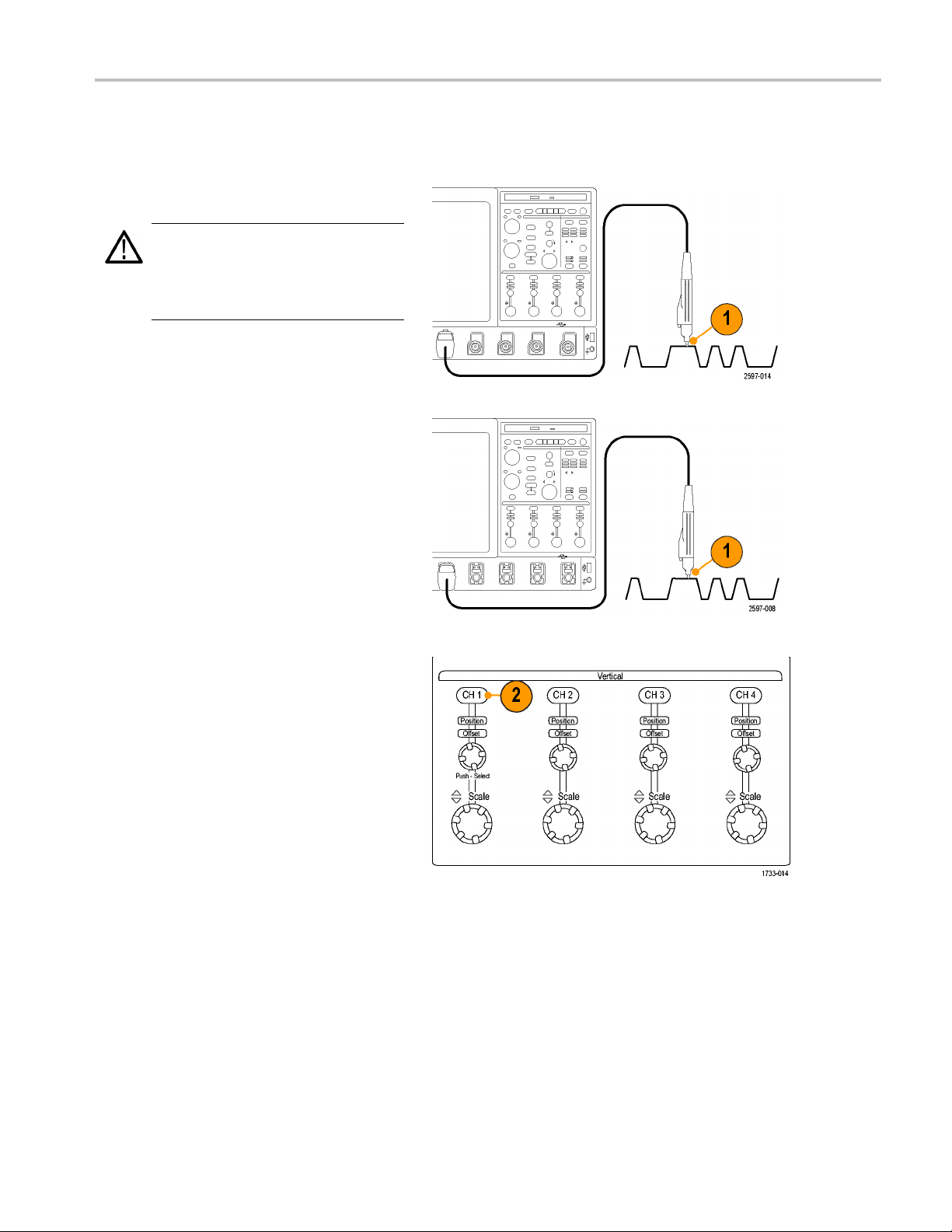
Using FastFrame Mode
FastFrame allows you to capture many trigger events as single records in a larger record, and then view and measure
each record individually. Time Stamps display the absolute trigger time for a specific frame and the relative time between
of two specified frames.
triggers
1. Push AUTOSET to set the horizontal,
vertical, and trigger controls or set the
s manually.
control
DPO7000 Series and DPO/DSA70000/B Series Quick Start U ser M anual 39
Page 60
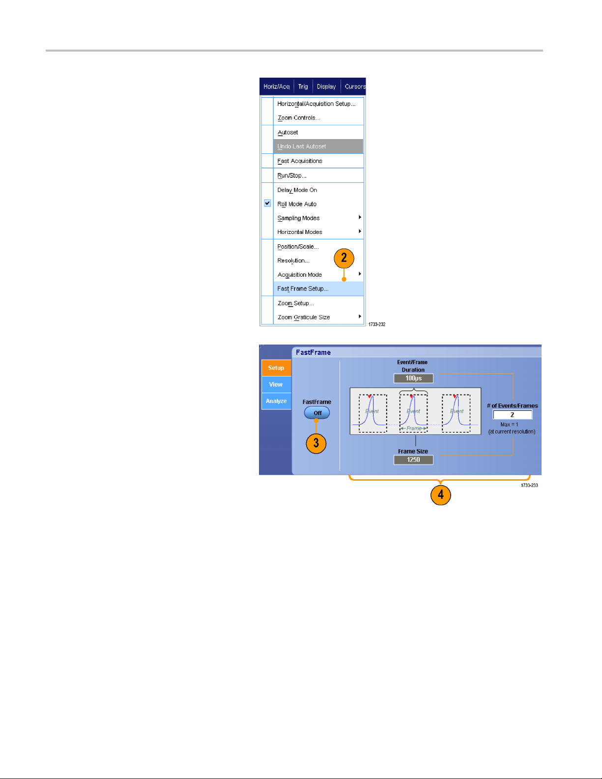
Acquisition
2. Select Horiz/Acq > FastFrame Setup....
3. Push FastFrame On.
4. Select Frame Size and # of Events
Frames. Then use the multipurpose
knobs to set each one. Number of
frames represents the number of trigger
events that will be captured. Frame size
is the number of samples that will be
stored with each trigger event (or frame.)
The number of frames will be reduced if
there is insufficient memory to store all
the records.
40 DPO7000 Series and DPO/DSA70000/B Series Quick Start User Manual
Page 61
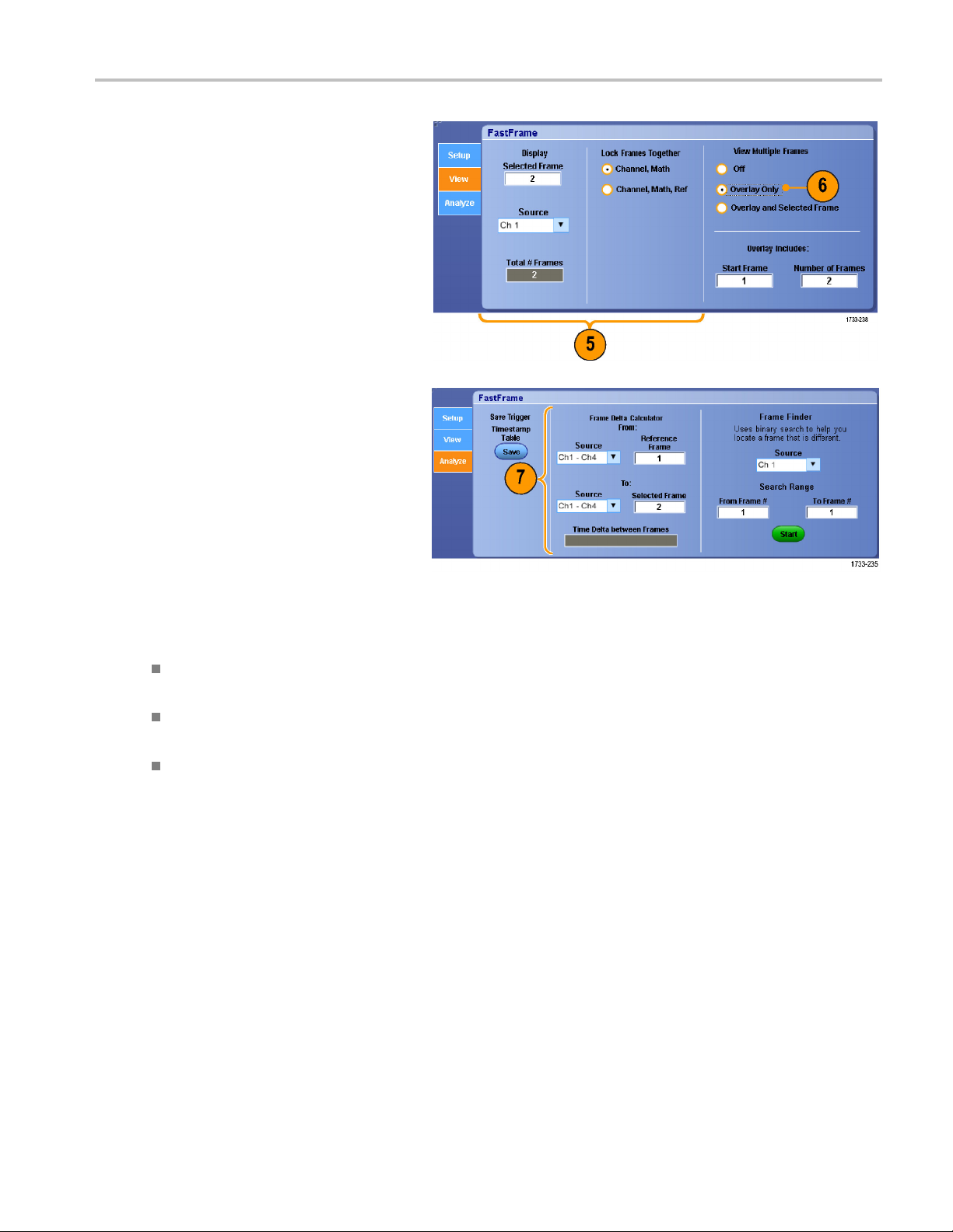
Acquisition
5. Use the Frame Vi
the frame that you want to view.
6. To view multiple frames superimposed
over each other, select Overlay.
7. Use the Time Stamps controls to select
the source for, and frame number of, the
reference
is the starting point when measuring the
relative time between two frames.
ewing c ontrols to select
frame. The reference frame
Quick T
ips
Use FastFrame when you want to preserve the data associated with each trigger event for further analysis or visual
inspections.
Use FastFrame when you want to capture multiple events that have long dead times between them that are of no
interest to you.
Multiple frames are best viewed with the Normal, Green, or G ray color palettes because the dark blue selected frame
may be hard to distinguish if you use Temp or Spectral.
DPO7000 Series and DPO/DSA70000/B Series Quick Start U ser M anual 41
Page 62

Acquisition
Using FastFrame Frame Finder
Frame finder allows you to find a FastFrame frame that is different from other frames.
1. Select the s ource of the FastFrame
frames.
2. Set the Search Range by entering the
From Frame # and the To Frame #.
3. Push Run/Stop to stop acquisitions.
4. Push Start to start the search.
Frame Finder searches for and displays a
different frame.
5. If the anomaly you a re looking for is not
in the displayed frame, push No.Frame
Finder searches for another different
frame.
6. Iftheanomalyyouarelookingforisin
the displayed frame, push Yes.
7. If you are done searching, push Stop.
42 DPO7000 Series and DPO/DSA70000/B Series Quick Start User Manual
Page 63

8. Push Run/Stop to restart acquisitions.
Using TekLink and MultiScope Trigger
To get more than 4 channels associated with a single trigger event, get more than 4 channels looking for a problem on a
channel, or
NOTE. When using MultiScope Trigger, the B Triggers are not available.
build a big AND gate with more than 4 inputs use TekLink.
Acquisition
Link2Ins
1. Connect two instruments using a TekLink
cable.
2. TekLink connection status is displayed in
the horizontal readout.
truments
DPO7000 Series and DPO/DSA70000/B Series Quick Start U ser M anual 43
Page 64

Acquisition
3. Select Trig > A Event (Main) Trigger
Setup....
4. Select the M
5. Enable Mult
selecting Enable MultiScope Triggering
(with TekLink).
6. Select Sends Trigger to enable the
instrumen
the instrument-instrument setup. The
other instrument is automatically set to
receive t
If not using a hub, all trigger types are
available on the instrument supplying the
trigger.
ultiScope Trigger tab.
iScope Triggering by
t to trigger both instruments in
he trigger.
44 DPO7000 Series and DPO/DSA70000/B Series Quick Start User Manual
Page 65

7. To calibrate the MultiScope Trigger,
press the Calibrate button.
Link Multiple Instruments
Two or more instruments can be connected using a TekLink Hub.
1. Connect two or more instruments using
a TekLink hub and cables.
Acquisition
2. TekLink connection status is displayed in
the horizontal readout.
3. Select Trig > A Event (Main) Trigger
p....
Setu
DPO7000 Series and DPO/DSA70000/B Series Quick Start U ser M anual 45
Page 66

Acquisition
4. Select the M ultiScope Trigger tab.
5. Enable MultiScope Triggering by
selecting Enable MultiScope Triggering
(with TekLink
).
6. Select Contr
instrument to supply a trigger in the
TekLink setup. The other instruments are
automatical
7. Select AND or select OR to combine all
contributed triggers before triggering all
instruments in the TekLink setup.
AND triggering with a hub works with
edge and pattern trigger types.
OR triggering with a hub works with all
trigger types.
8. To align the MultiScope Trigger, press
the Align button.
ibute to enable the
ly set to receive the trigger.
9. If you want the instrument to scan
the TekLink network to see which
ments are connected to the TekLink
instru
network, press the Refresh button.
10. When MultiScope triggering is enabled,
it displays in the trigger readout.
46 DPO7000 Series and DPO/DSA70000/B Series Quick Start User Manual
Page 67

Pinpoint Triggers
The Pinpoint trigger system comes with advanced trigger types that are usable on both A and B triggers, and it can reset the
trigger sequence if the B event does not occur after a specific number of events or a specific time. Pinpoint triggers support
capture of events based on the most complex trigger event or sequence of trigger events.
This section contains concepts and procedures for using the trigger system.
Triggering Concepts
Trigger Event
The trigger event establishes the time-zero point in the waveform record. All waveform record data are located in time with
respect to that point. T he instrument continuously acquires and retains enough sample points to fill the pretrigger portion of
the waveform record. When a trigger event occurs, the instrument starts acquiring samples to build the posttrigger portion of
the waveform record (displayed after, or to the right of, the trigger event). Once a trigger is recognized, the instrument will not
accept another trigger until the acquisition is complete and the holdoff time has expired.
Trigger Modes
Pinpoint Trigge
rs
ger mode determines how the instrument behaves in the absence of a trigger event:
The trig
Normal t
waveform record acquired remains on the display. If no last waveform e xists, no waveform is displayed.
Auto trigger mode enables the instrument to acquire a waveform even if a trigger does not occur. Auto mode uses a timer
that starts after a trigger event occurs. If another trigger event is not detected before the timer times out, the instrument
forces
Auto mo
display. The waveform will appear to roll across the screen. If valid triggers occur, the display will become stable.
In edge-trigger mode, you can also force the instrument to trigger by pushing the Force Trigger button on the Trigger
Setup control window.
Select the trigger mode in the Trig > Mode menu. For more information, see the instrument online help.
Trig
Trigger holdoff can help stabilize triggering, by extending the period in which further trigger recognition is suppressed after
initiating an acquisition. Such an extension can help the system skip over the remaining events of a recurring burst of events,
and thus always trigger on the first event in each burst. Adjust holdoff to obtain stable triggering when the instrument is
triggering on undesired trigger events.
Set the trigger holdoff in the Trig > Holdoff menu. For more information, see the instrument online help.
rigger mode enables the instrument to acquire a waveform only when it is triggered. If no trigger occurs, the last
a trigger. The length of time it waits for a trigger event depends on the time base setting.
de, when forcing triggers in the absence of valid triggering events, does not synchronize the waveform on the
ger Holdoff
DPO7000 Series and DPO/DSA70000/B Series Quick Start U ser M anual 47
Page 68

Pinpoint Trigge
Trigger Coupling
Trigger coupling determines what part of the signal is passed to the trigger circuit. Edge triggering can use all available
coupling types: AC, DC, Low Frequency Rejection, High Frequency Rejection, and Noise Rejection. All other trigger
types use DC coupling only.
Select the trigger coupling in the Trig > A Event (Main) Trigger Setup menu. For more information, see the instrument
online help.
Horizontal Position
Horizontal position defines where the trigger occurs on the waveform record. It lets you choose how much the instrument
acquires be
part that occurs after the trigger is the posttrigger portion.
Pretrigger data can be valuable when troubleshooting. For e xample, if you are trying to find the cause of an unwanted glitch
in your test circuit, you can trigger on the glitch and make the pretrigger period large enough to capture data before the
glitch. By
Alternatively, if you w ant to see what is happening in your system as a result of the trigger event, make the posttrigger period
large enough to capture data after the trigger.
rs
fore and after the trigger event. The part of the record that occurs before the trigger is th e pretrigger portion. The
analyzing what happens before the glitch, you may uncover information that helps you find the source of the glitch.
Slope an
The slope control determines whether the instrument finds the trigger point on the rising or the falling edge of a signal. The
level control determines where on that edge the trigger point occurs.
d Level
Delayed Trigger System
You can trigger with the A (Main) trigger system alone or you can combine the A (Main) trigger with the B (Delayed) trigger
to trigger on sequential events. When using sequential triggering, the A trigger event arms the trigger system, and the B
er event triggers the instrument when the B trigger conditions are met. A and B triggers can (and typically do) have
trigg
separate sources. The B trigger condition can be based on a time delay or a specified number of events. (See page 53,
Using A (Main) and B (Delayed) Triggers.)
48 DPO7000 Series and DPO/DSA70000/B Series Quick Start User Manual
Page 69

Choosing a Trigger Type
Pinpoint Trigge
rs
Your instrume
the Trigger Setup control window.
NOTE. Some trigger type selections are not available on some instruments.
1. Push EDGE.
2. Set the source, slope and mode. To set
the couplin
menu.
3. To select one of the other trigger types,
do one of the following:
nt allows you to modify basic trigger parameters from the front panel or set up more advanced triggers in
g use the Trig > Edge Setup
Push ADVANCED
Select a trigger type directly from the
Trig menu
DPO7000 Series and DPO/DSA70000/B Series Quick Start U ser M anual 49
Page 70

Pinpoint Trigge
4. Complete the trigger setup using the
rs
controls displayed for the trigger type.
The controls t
depending on the trigger type.
o set up the trigger vary
Pinpoint T
Trigger Type Trigger Conditions
Edge
Glitch
Width
Runt
Window
Timeout
Transition
Serial Trigger on 64-bit serial pattern at data rates up to 1.25 Gb/s (<4 GHz models) and
Pattern
rigger Selections
Trigger on a rising or falling edge, as defined by the slope control. Coupling choices
are DC, AC, LF Reject, HF Reject, and Noise Reject.
Trigger on a pulse narrower (or wider) than the specified width or ignore glitches
narrower (or wider) than the specified width.
Trigger on pulses that are inside or outside a specified time range. Can trigger
on positive or negative pulses.
Trigger on a pulse amplitude that crosses one threshold but fails to cross a second
threshold before recrossing the first. Can detect positive or negative runts, or only
those wider than a specified width. These pulses can also be qualified by the logical
state of other channels.
Trigger when the input signal rises above an upper threshold level or falls below a
lower threshold level. Trigger the instrument as the signal is entering or leaving the
threshold window. Qualify the trigger event in terms of time by using the Trigger
When Wider option, or by the logical state of other channels using the Trigger When
Logic option.
Trigger when no pulse is detected within a specified time.
Trigger on pulse edges that traverse between two thresholds at faster or slower rates
than the specified time. The pulse edges can be positive or negative.
40-bit serial patterns up to 3.125 Gb/s (≥4 GHz models only) or 5 Gb/s (≥4GHzB
models). Lock on a pseudo-random bit sequence. Requires Option PTM or PTH.
This mode includes clock recovery. Push the Push Set 50% knob to reinitialize
clock recovery.
Pattern Lock automatically finds and locks on a long repeating pseudo-random bit
sequence (PRBS). This lock means that the instrument knows the bit l ength of the
pseudo-random bit sequence and can predict when the cycle repeats. Pattern Lock
enables the instrument to take samples at specific locations in a data pattern with
outstanding timebase accuracy.
Trigger when logic inputs cause the selected function to become True or False. You
can also specify that the logic conditions must be satisfied for a specific amount of
time before triggering.
50 DPO7000 Series and DPO/DSA70000/B Series Quick Start User Manual
Page 71

Pinpoint Trigge
rs
Trigger Type Trigger Condit
State Trigger when a
be True or False when the clock input changes state.
Setup/ Hold Trigger when a logic input changes state inside of the setup and hold times relative
to the clock. The mode triggers on a setup and hold violation.
Comm
Video
SPI Trigger on Serial Peripheral Interface (SPI) signals.
I2C Trigger on Inter-IC Control (I2C) signals: start, stop, repeated start, missing
RS-232 Trigger
CAN Trigger on CAN Bus signals.
Trigger in conjunction with mask testing on communications codes and standards.
The controls work together to define the parameters for the trigger event (available
with Option
50% knob to reinitialize clock recovery.
Trigger on specified fields or lines of a composite video signal. Only composite
signal formats are supported.
acknowle
ions
ll of the logic inputs to the selected logic function cause the function to
MTM or MTH). This mode includes clock recovery. Push the Push Set
dge, address, data, and address and data.
on RS-232 signals.
DPO7000 Series and DPO/DSA70000/B Series Quick Start U ser M anual 51
Page 72

Pinpoint Trigge
rs
Checking Trigger Status
You can check the trigger status from the status lights on the front panel or from the readout.
Check the ARM, READY, and TRIG’D
front-panel controls to determine the trigger
status.
If TRIG’D is on, the instrument has
recognized a valid trigger and is filling
the posttrigger portion of the waveform.
If READY is on, the instrument can
accept, and is waiting for, a valid trigger
to occur. Pretrigger data has been
acquired.
If ARM is on, the trigger circuitry is filling
the pretrigger portion of the waveform
record.
If both TRIG’D and READY are on,
a valid A event trigger has been
recognized and the instrument is waiting
for a delayed trigger. When a delayed
trigger is recognized, the posttrigger
portion of the delayed waveform will fill.
If ARM, TRIG’D, and READY are off,
acquisitions have stopped.
To quickly determine the settings of some
key trigger parameters, check the Trigger
readout at the bottom of the display. The
readouts differ for edge and the advanced
triggers:
1. A trigger source = Ch1
2. Trigger slope = rising edge
3. Trigger level
4. Time base
52 DPO7000 Series and DPO/DSA70000/B Series Quick Start User Manual
Page 73

Using A (Main) and B (Delayed) Triggers
You can use the A Event (Main) trigger for simple signals or combine it with the B Event (Delayed) trigger to capture
more complex signals. After the A Event occurs, the trigger system looks for the B Event before triggering and displaying
the waveform.
A Trigger
1. Select Trig > A Event (Main) Trigger
Setup....
2. Set the A trigger type and source in the
A Event tab.
Pinpoint Trigge
rs
B Trigger (Delayed)
NOTE. B triggers are not available if
MultiScope Trigger is enabled.
3. Choose a function in the A →B Seq tab.
4. Set the trigger delay time or the number
of B events.
DPO7000 Series and DPO/DSA70000/B Series Quick Start U ser M anual 53
Page 74

Pinpoint Trigge
5. Set the B trigger characteristics in the B
6. Select Normal Trigger Mode and Auto
rs
Event (Delayed) tab.
Holdoff in the Mode tab.
Trigger on B Event
The A trigger arms the instrument.
Posttrigger acquisition starts on the n th B
event.
54 DPO7000 Series and DPO/DSA70000/B Series Quick Start User Manual
Page 75

B Trigger After Delay Time
The A trigger arms the instrument.
Posttrigger a
edge after the trigger delay time.
cquisition starts on the first B
Pinpoint Trigge
rs
Triggering
You can specify a condition to reset the
trigger system if it occurs before the B trigger
event. Whe
trigger system stops waiting for the B event
and returns to waiting for the A event.
with Reset
n the reset event occurs, the
Quick Tips
ger delay time and horizontal delay time are independent functions. When you establish a trigger condition using
B-trig
either the A trigger alone or the A and B triggers together, you can also use horizontal delay to delay the acquisition
by an additional amount.
cting Trigger Position
Corre
Trigger position correction corrects for differences in the data path and the trigger path to more accurately place the trigger
on the displayed waveform. Trigger position correction can also use averaging to more accurately place the trigger on noisy
signals. To more accurately place edge triggers on the display, perform the following procedure.
DPO7000 Series and DPO/DSA70000/B Series Quick Start U ser M anual 55
Page 76

Pinpoint Trigge
rs
1. To more accurat
on the display, check Enhanced
Triggering. To more accurately place
the trigger on n
Optimized for Noisy Signals.
The Optimized for Noisy Signals
selection is o
Triggering is selected.
ely place the trigger
oisy signals, also check
nly available if Enhanced
SendingE-mailonTrigger
You must configure e-mail on event before performing the following procedure. (See page 131, Setting Up E-mail on Event.)
1. Select Trig > A Event (Main) Trigger
Setup....
2. Select the Mode tab.
3. Under E-mail on Trigger, click On, and
then click Setup. (See page 131, Setting
Up E-mail on Event.)
56 DPO7000 Series and DPO/DSA70000/B Series Quick Start User Manual
Page 77

Using Horizontal Delay
Use horizontal delay to acquire waveform
detail in a reg
trigger location by a significant interval of
time.
1. Push DELAY.
2. Adjust the delay time with the horizontal
POSITION control, or enter the delay
time in the control window.
3. Adjust the horizontal SCALE to acquire
the detail that you need.
ion that is separated from the
Pinpoint Trigge
rs
Quick Tips
Use MultiView Zoom and Horizontal Delay together to magnify a delayed acquisition.
Toggle Horizontal Delay on and off to quickly compare si gnal details at two different areas of interest, one near the
trigger location and the other centered at the delay time.
DPO7000 Series and DPO/DSA70000/B Series Quick Start U ser M anual 57
Page 78

Display a Wavefo
rm
Display a Wave
This section contains concepts and procedures for displaying a w aveform. Detailed information is available in the online help.
form
Setting the Display Style
To set the display style select Display >
Display Style, and then select one of the
following styles:
Displays waveforms with
lines drawn between
record points.
Displays waveform
record points as dots on
the screen.
Displays the actual
samples. Interpolated
re not displayed.
points a
58 DPO7000 Series and DPO/DSA70000/B Series Quick Start User Manual
Page 79

Setting the Display Persistence
Display a Wavefo
rm
Select Displa
then select the type of persistence.
No persistence shows record points for
the current acquisition only. Each new
waveform rec
acquired record for a channel.
Infinite persistence continuously
accumulates record points until you
change one o
settings. Use for displaying points that
may occur outside the normal acquisition
envelope.
Variable p
points for a specified time interval.
Each record point decays independently
accordin
Reset per
1. To set the variable persistence time,
select D
Persistence Controls....
2. Click Variable, Persist Time, and then
use the multipurpose knobs to set the
persis
y > Display Persistence, and
ord replaces the p reviously
f the acquisition display
ersistence accumulates record
gtothetimeinterval.
sistence clears the persistence.
isplay > Display Persistence >
tence time.
DPO7000 Series and DPO/DSA70000/B Series Quick Start U ser M anual 59
Page 80

Display a Wavefo
rm
Setting the Display Format
The instrument can display waveforms in two different formats. Choose the format that best suits your needs.
Select Display > Display F ormat.
Select YT format to show a signal
amplitude as it varies over time.
Select XY format to compare the
amplitude of waveform records point by
point:
The following channels are compared:
Ch 1 (X) and Ch 2 (Y),
Ch 3 (X) and Ch 4 (Y),
Ref 1 (X) and Ref 2 (Y),
Ref3(X)andRef4(Y)
Select XYZ format to compare the
voltage levels of the Ch 1 (X) and Ch 2
(Y) waveform records point by point as
in XY format. The displayed waveform
intensity is modulated by the Ch 3
(Z) waveform record. XYZ format is
triggered. A -5 division signal (including
position and offset) on Ch 3 produces
a blank screen; a +5 division signal
produces full intensity.
Quick Tips
XY format is particularly useful for studying phase relationships such as Lissajous Patterns.
XY format is a dot-only display, although it can have persistence. The Vector style selection has no effect when you
tXYformat.
selec
60 DPO7000 Series and DPO/DSA70000/B Series Quick Start User Manual
Page 81

Selecting the Waveform Interpolation
Select Display > Waveform Interpolation,
and then select one of the following:
Sin(x)/x interpolation computes record
points using a curve fit between the
actual samples acquired.
Linear interpolation computes record
points between actual acquired samples
by using a straight line fit.
Display a Wavefo
rm
Quick Tips
Sin(x)/x interpolation is the default interpolation mode. It requires fewer actual sample points than linear interpolation to
accurately represent the waveform.
Adding Screen Text
1. Select Display > Screen Text.
DPO7000 Series and DPO/DSA70000/B Series Quick Start U ser M anual 61
Page 82

Display a Wavefo
2. Enter up to eight independent lines of
text.
3. Click Text Off or On to turn the text
display on and
rm
off.
4. Click Font or
color of the screen text.
5. Click Controls to open the Text
Properties control w indow for positioning
of the text o
6. Click Clear
selected line.
Color to select the font and
n the display.
to erase the entire text of the
Quick Tips
You can click and drag screen text to reposition it on the screen.
62 DPO7000 Series and DPO/DSA70000/B Series Quick Start User Manual
Page 83

Setting the Graticule Style
To set the graticule style, select Display >
Graticule Style, and then select one of the
following sty
les:
Use for quick
waveform parameters.
Use for full-screen
measurements with
cursors and automatic
readouts when
cross-hairs are not
needed.
Use for making quick
estimates of waveforms
while leaving more room
for automatic readouts
and other data.
Use with automatic
readouts and other
screen text when display
features are not needed.
estimate of
Display a Wavefo
rm
Use for NTSC video
signals.
Use for video signals
other than NTSC.
DPO7000 Series and DPO/DSA70000/B Series Quick Start U ser M anual 63
Page 84

Display a Wavefo
rm
Setting the Trigger Level Marker
1. Select Displa
2. Select one of t
Short displa
side of the graticule.
Long displays a horizontal line
across the graticule.
Off turns off the trigger level marker.
y > Objects....
he following:
ys a short arrow on the
Displaying the Date and Time
1. Select Display > Objects....
2. Toggle the display of the date and time
on the graticule. Use the Utilities menu
to set the date and time.
64 DPO7000 Series and DPO/DSA70000/B Series Quick Start User Manual
Page 85

Using the Color Palettes
Display a Wavefo
rm
Select Displa
FastAcq/WfmDB Palette, and then select
one of the following color schemes for the
waveform and g
Normal displ
levels for best overall viewing. The color
of each channel waveform matches the
color of the
vertical knob.
Temperature Grading displays areas of
the waveform with the highest sample
density in
lowest sample density appear in blue
shades.
Monochrome Green displays areas of
the wavef
density in lighter green shades. The
areas of lowest sample density appear
in darker
resembles analog oscilloscope displays.
y > Record View Palette or
raticule:
ays hues and lightness
corresponding front-panel
red shades. The areas of
orm with the highest sample
green shades. It most closely
Spectral Grading displays areas of
the waveform with the highest sample
density in blue shades. The areas of
lowest sample density appear in red
shades.
Monochrome Gray displays areas of
the waveform with the highest sample
density in lighter gray shades. The
areas of lowest sample density appear in
darker gray shades.
User displays the waveform in a
user-defined color.
Quick Tips
Choose one of the c olor grading palettes in the Disp lay > Colors control window to see different sample densities
represented in different colors.
There are two color palettes, one for Record View and one for FastAcq/WfmDB.
DPO7000 Series and DPO/DSA70000/B Series Quick Start U ser M anual 65
Page 86

Display a Wavefo
rm
Setting the Reference Colors
Select Display > Colors..., and then select
one of the following:
Default uses the default system color for
reference waveforms.
Inherit uses the same color for the
reference waveform as the original
waveform.
Setting Math Colors
Select Display > Colors..., and then select
one of the following:
Default uses the default system color for
math waveforms.
Inherit uses the same color for the
math waveform as the lowest numbered
channel waveform the math function is
based on.
Quick Tips
The default color for math and reference waveforms are different for each waveform.
Using MultiView Zoom
Use the MultiView Zoom function to magnify a waveform vertically, horizontally, or in both dimensions. Zoomed waveforms
can also be aligned, locked, and automatically scrolled. Scale and Position affect only the display, not the actual waveform
data.
1. Push M ultiView Zoom to split the screen
and add a zoom graticule.
66 DPO7000 Series and DPO/DSA70000/B Series Quick Start User Manual
Page 87

2. Push HORIZ or VERT to select which
axis to magnify in the zoom graticule.
Use the multip
scale and position of the magnified
waveform.
In this examp
the top half of the graticule and the
zoomed graticule is the bottom half of
the graticul
NOTE. You can hide or display zoomed
waveforms by pressing Waveforms Hide and
then checki
display.
3. To adjust the zoom graticule size, select
Zoom Graticule Size from either the
Vertical or Horiz/Acq menus.
urpose knobs to adjust
le the main graticule is
e.
ng which zoomed waveforms to
Display a Wavefo
rm
4. To turn zoom off, push the front-panel
button.
Quick Tips
You can also use the Zoom Setup menu to change the graticule size of the zoomed waveform.
DPO7000 Series and DPO/DSA70000/B Series Quick Start U ser M anual 67
Page 88
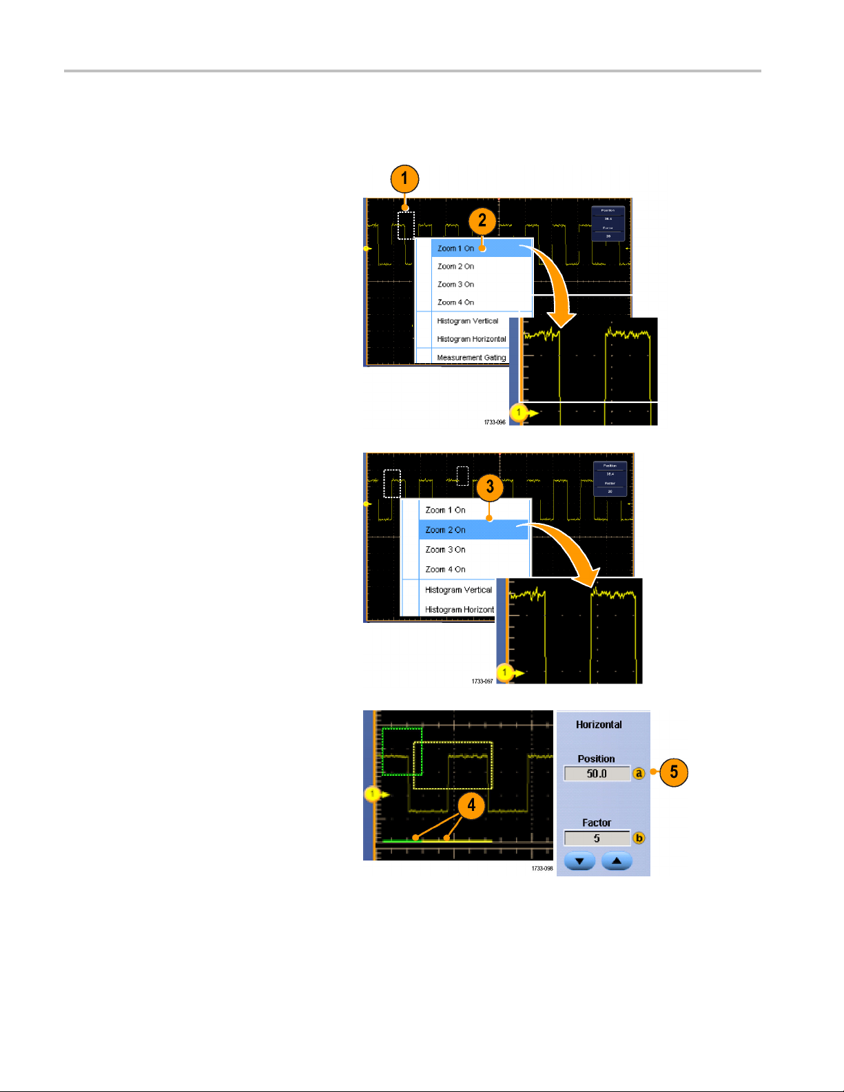
Display a Wavefo
rm
Zooming in Multiple Areas
When you want to view and compare multiple a reas of one record at the same time, use the following procedure.
1. Click and drag a box around the area of
the waveform that you want to zoom.
2. Select Zoom 1 On.
3. Click and drag a box around another
area of the waveform that you want to
zoom, and then select Zoom 2 On.
4. To adjust the zoomed area horizontally,
click the horizontal marker below the
Zoom box to select the zoomed area.
5. Use the multipurpose knobs to adjust
the horizontal position and factor of the
selected zoom area.
68 DPO7000 Series and DPO/DSA70000/B Series Quick Start User Manual
Page 89

Display a Wavefo
rm
6. To adjust the zo
select Vertical > Zoom Setup...,
click a vertical field, and then use the
multipurpose
Position and Factor.
omed area vertically,
knobs to adjust the Vertical
Quick Tips
To clear th
You c a n tu
Push the M
To reposi
e zoom area, click Position Factor Reset from the Zoom Setup control window.
rn each zoom display on and off from the Zoom Setup control window.
ultiView Zoom button to toggle all zoom displays on and off.
tion the zoomed area horizontally, click and drag the horizontal marker at the bottom of the zoom box.
Lock and Scroll Zoomed Waveforms
1. To use Lock and Scroll select Zoom
Setup... from either the Vertical or
Horiz/Acq menu, and then select the
Lock and Scroll tab.
2. To scroll a single zoomed area, select a
Zoom 1-4 check box, and then click an
Auto Scroll button.
DPO7000 Series and DPO/DSA70000/B Series Quick Start U ser M anual 69
Page 90

Display a Wavefo
rm
3. To s c roll multi
simultaneously, click Lock, and then
select the Zoom1-4 check boxes that
you want to scr
Locking the zoomed areas locks in their
relative horizontal position. Changing
the horizont
zoomed area changes them all.
ple zoomed areas
oll through.
al position of one locked and
Quick Tips
When multiple zoom areas are selected but not locked, the zoom area with the highest number will autoscroll, while the
other zoo
m areas remain stationary.
70 DPO7000 Series and DPO/DSA70000/B Series Quick Start User Manual
Page 91

Hide Waveforms in the Zoomed Window
Display a Wavefo
rm
1. To hide or view
Setup... from either the Vertical or
Horiz/Acq menu, press Controls, and
then press Wav
2. Select the zoomed area that contains
the waveform you want show or hide.
3. Uncheck the channel, math, or reference
waveform you want to hide.
waveforms, select Zoom
eforms Hide.
DPO7000 Series and DPO/DSA70000/B Series Quick Start U ser M anual 71
Page 92

Display a Wavefo
rm
Searching and Marking Waveforms
You can mark locations of interest in the acquired waveform. These marks help you limit your analysis to particular regions of
the waveform. You can mark areas of the waveform automatically, if they meet some special criteria, or you can manually
mark each item of interest. You can jump from mark to mark (area of interest to area of interest). With the Advanced Search
and Mark option, you can automatically search and mark m any of the same parameters that you can trigger on. Many
search parameters don’t have the time limits as triggers. You can search on math and reference waveforms. You can find
all of the acquired events of a certain type.
Search marks provide a way to mark a waveform r egion for reference. You can set marks automatically with search
criteria. You can search for and mark regions with particular edges, pulse widths, runts, logic states, rise/fall times, setup
and hold violations, and bus search types.
To Manually Set and Clear (delete) Marks:
1. Press Multiview Zoom. Zoom 1 is used
with marks.
2. Select Analyze > Search.
72 DPO7000 Series and DPO/DSA70000/B Series Quick Start User Manual
Page 93
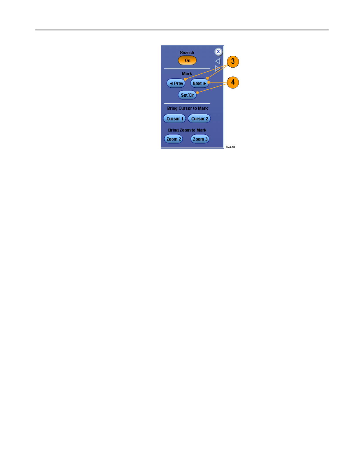
3. Move (the zoom box) to the area on
the waveform where you want to set
(orclear)ase
multipurpose knob.
Push the Next or Prev button to jump to
an existing m
arch mark by turning a
ark.
Display a Wavefo
rm
4. Push Set Clr
If no search mark is at the screen center,
the instrument will add one.
When a mark i
zoom factor is saved. When you use
Next or Prev to move between marks,
the zoom fa
.
s created, the horizontal
ctor is restored.
DPO7000 Series and DPO/DSA70000/B Series Quick Start U ser M anual 73
Page 94

Display a Wavefo
5. Investigate your waveform by moving
from search mark to search mark. Use
the Next or Pre
one marked location to another, without
adjusting any other controls.
6. Delete a mark. Push the Next or Prev
button to jump to the mark you want to
clear. To rem
mark, push Set Clr. It works on both
manually and automatically created
marks.
rm
v buttontojumpfrom
ove the center-positioned
To Automa
1. Select Analyze > Search.
2. Select the desired search type from the
menu.
The search menu is similar to the trigger
menu.
Edge type is standard; other search
types are optional.
tically Set and Clear (delete) Search Marks:
74 DPO7000 Series and DPO/DSA70000/B Series Quick Start User Manual
Page 95

3. Set up your search from the Configure
tab. To copy the trigger setup or a search
setup, press S
ettings Copy.
Display a Wavefo
rm
4. From the Copy S
where to copy the settings from and
where to copy the settings to. Press
Copy and then
5. To modify the current search setup,
e displayed controls. Displayed
adjust th
controls vary depending on the selected
search.
ettings window, select
Close.
6. If not already on, press Search to toggle
search to on.
DPO7000 Series and DPO/DSA70000/B Series Quick Start U ser M anual 75
Page 96
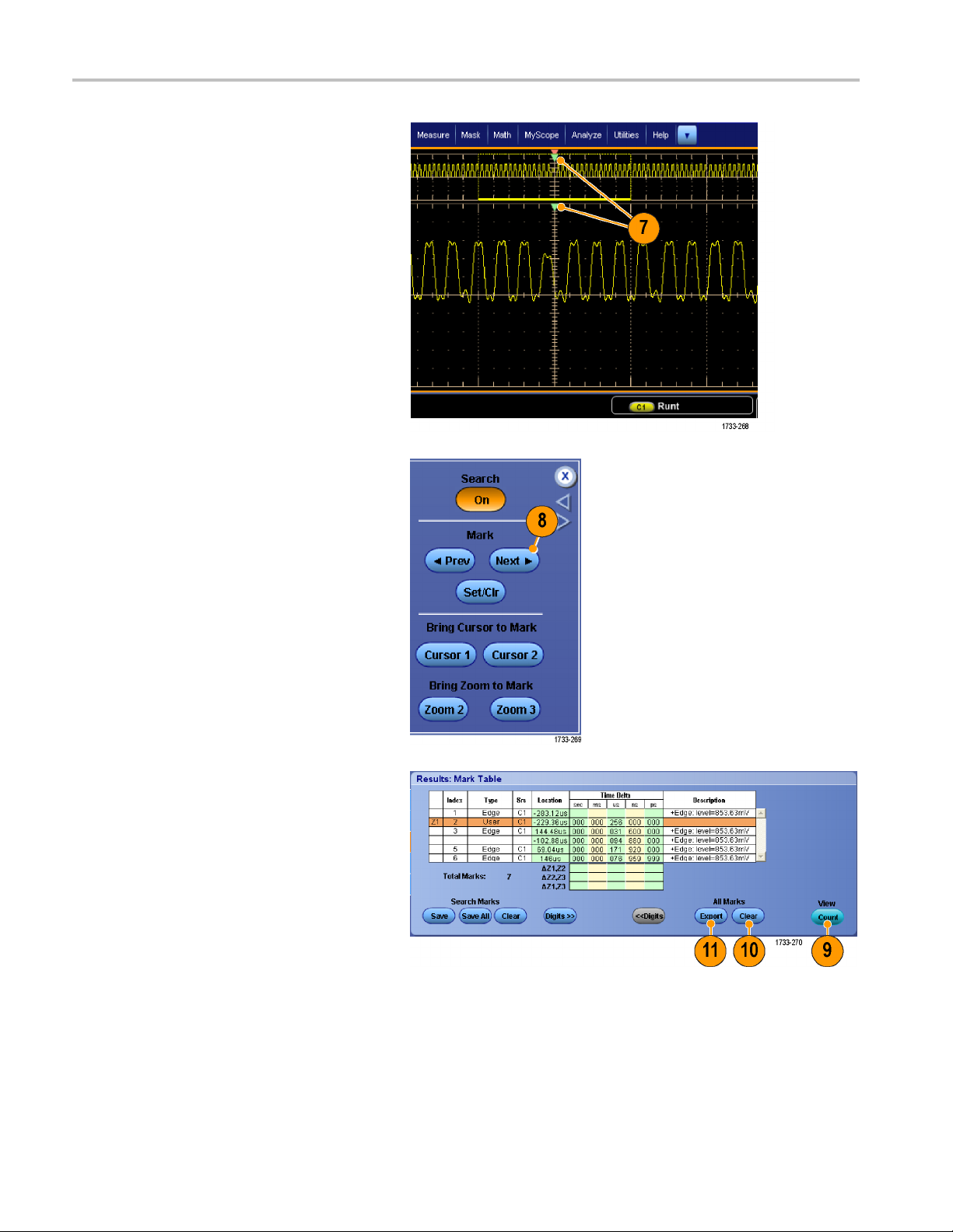
Display a Wavefo
7. On the screen, triangles show the
location of automatic marks and white
triangles sho
locations. These appear on both normal
and zoomed waveform views.
8. You can quickly investigate your
waveform by moving from mark to mark
with the Next and Prev arrow buttons.
No other adjustments are needed.
rm
w the custom (user-defined)
9. To toggle between the display of search
s counts or Marks time, select the
event
Results tab and press View Count.
10. To clear all marks from the table, press
All Marks Clear.
11. To export the Mark Table to a file, p res s
arks Export.
All M
76 DPO7000 Series and DPO/DSA70000/B Series Quick Start User Manual
Page 97

Display a Wavefo
rm
12. To convert a mar
marks, press Search Marks Save or
Save All.
13. To remove the currently highlighted row
from the Mark T
Clear.
14. To toggle between showing mark
locations in engineering notation or in
high precisi
15. To toggle th
and off, select the View tab and press
Show Marks.
korallmarkstouser
able, press Search Marks
on form, press Digits.
e display of mark triangles on
DPO7000 Series and DPO/DSA70000/B Series Quick Start U ser M anual 77
Page 98

Display a Wavefo
16. To stop acquisitions if a match is found,
select the Mode tab and check Stop
Acquisition i
Quick Tips.
Search is performed only on acquired data. Set up the instrument to acquire the data you are searching for.
Set the sample rate so the search event is discernible. You can search for a glitch that is wider than a couple of
sample intervals.
You can copy trigger settings to search for o ther locations in your acquired waveform that meet the trigger conditions.
You can copy search settings to your trigger.
Edge search marks are created without zoom factors. Other search types create marks with an appropriate zoom factor.
rm
f event found.
Pressing Bring Zoom to Mark Zoom 2 or Zoom 3 displays the corresponding zoom view with the same zoom parameters
as Zoom 1.
Custom (User) marks a re saved with the waveform when the waveform is saved and when the setup is saved.
Automatic search marks are not saved with the waveform when the waveform is saved. However, you can easily
recapture them by reusing the search function.
Thesearchcriteriaaresavedinthesavedsetup.
Search includes the following search capabilities:
Search Description
Edge
Glitch Searches for pulses narrower (or wider) than the specified width, or ignores glitches
Pulse Width
Setup & Hold Search for violations of user-specified setup and hold times.
Runt
Window
Pattern
Searches for edges (rising or falling) with a user-specified threshold level.
narrower (or wider) than the specified width.
Searches for positive or negative pulse widths that are >, <, =, or ≠ a user-specified pulse
width.
Searches for positive or negative pulses that cross one amplitude threshold but fail to cross
a second threshold before crossing the first again. Search for all runt pulses or only those
withaduration>,<,=,or≠ a user-specified time.
Searches for a signal that is entering or leaving the threshold window. Q ualify the search
in terms of time by using the When Wider option, or by the logical state of other channels
using the When Logic option.
Search for a logic pattern (AND, OR, NAND, or NOR) across multiple w aveforms with each
input set to either High, Low, or Don’t Care. Search for when the event goes true, goes
false, or stays valid for > , <, =, or ≠ a user-spec ified time. Additionally, you must define one
of the inputs as a clock for synchronous (state) searches.
78 DPO7000 Series and DPO/DSA70000/B Series Quick Start User Manual
Page 99

Search Description
Transition
Timeout
Search for ris
Searches for n
State Searches for
be True or False when the clock input changes state.
Display a Wavefo
ing and/or falling edges that are >, <, =, or ≠ a user-specified time.
o pulse in a specified time.
when all of the logic inputs to the selected logic function cause the function to
rm
DPO7000 Series and DPO/DSA70000/B Series Quick Start U ser M anual 79
Page 100

Analyzing Wavef
orms
Analyzing Wav
Your instrument features cursors, automatic measurements, statistics, histograms, math, spectral analysis, and advanced
pass/fail tests to assist you in analyzing waveforms. This section contains concepts and procedures for analyzing waveforms.
Detailed information is available in the online help.
eforms
Taking Automatic Measurements
1. Select Measure > Measurement
Setup....
2. Select the channel, m ath or reference
waveform that you want to measure.
3. Using the tabs, select measurements in
five different categories.
4. To remove all measurements, click Clear
All.
5. To remove multiple measurements, click
and drag to select the measurements,
and then click Clear Selected.
80 DPO7000 Series and DPO/DSA70000/B Series Quick Start User Manual
 Loading...