


xx
ZZZ
DPO2000 and MSO2000 Series
Programmer Manual
*P077009701*
077-0097-01


xx
ZZZ
DPO2000 and MSO2000 Series
Programmer Manual
Revision A
www.tektronix.com
077-0097-01

Copyright © Tektronix. All rights reserved. Licensed software products are owned by Tektronix or its subsidiaries
or suppliers, and are protected by national copyright laws and international treaty provisions.
Tektronix products are covered by U.S. and foreign patents, issued and pending. Information in this publication
supersedes that in all previously published material. Specifications and price change privileges reserved.
TEKTRONIX and TEK are registered trademarks of Tektronix, Inc.
Contacting
Tektronix, Inc.
14150 SW Karl Braun Drive
P.O. Box 50
Beaverton, OR 97077
USA
For product information, sales, service, and technical support:
In North America, call 1-800-833-9200.
Worl dwi
Tektronix
0
de, visit www.tektronix.com to find contacts in your area.

Table of Contents
Getting Started ..... . ..... . ..... . ... . . ..... . ..... . ..... . ..... . ..... . ... . . . .... . ..... . ..... . ..... . ..... . ..... . ..... . 1-1
Setting Up Remote Communications . .... . ..... . ..... . ... . . ..... . ..... . ... . . . .... . ..... . ..... . ... . . ..... . . 1-1
Command Syntax.......................... .................................. ................................ ..... 2-1
Command and Query Structure ............................................................................ 2-1
Clearing the oscilloscope ..... . ... . . . .... . ..... . ..... . ..... . ..... . ..... ..... . ..... . ..... . ..... . ..... . ... . . . . 2-4
Command Entry.............................................................................................. 2-4
Constructed Mnemonics .................................................................................... 2-6
Argument Types..... .................................. ................................ ....................... 2-7
Command Groups .............................................................................................. 2-11
Acquisition Command Group . .... . ..... . ..... . ..... . ..... . ..... . ..... . ... . . ..... . ..... . ..... . ..... . ..... 2-11
Alias Command Group............................. .................................. ..................... 2-12
Bus Command Group ..................................................................................... 2-13
Calibration and Diagnostic Command Group .......................................................... 2-16
Cursor Command Group ............................... ................................ ................... 2-17
Display Command Group................................................................................. 2-18
Ethernet Command Group ................................................................................ 2-19
File System Command Group ............................... .................................. ........... 2-20
FilterVu Command Group ................................................................................ 2-21
Hard Copy Command Group .......................... ................................ ................... 2-22
Horizontal Command Group .................. ................................ ........................... 2-23
Mark Command Group........................... ................................ ......................... 2-23
Math Command Group................................. ................................ ................... 2-25
Measurement Command Group....................... ................................ ................... 2-26
Miscellaneous Command Group......................................................................... 2-29
PictBridge Command Group ................................ .................................. ........... 2-30
Save and Recall Command Group ....................................................................... 2-31
Search Command Group ............................. .................................. ................... 2-33
Status and Error Command Group...... ................................ ................................. 2-37
Trigger Command Group .................................... ................................ ............. 2-38
Vertical Command Group...... ................................ ................................ ........... 2-45
Waveform Transfer Command Group ................................................................... 2-48
Zoom Command Group ................................................................................... 2-55
Commands Listed in Alphabetical Order . ................................ ................................ ... 2-57
Status and Events ................................................................................................. 3-1
Registers ......................... ................................ ................................ ............. 3-1
Queues ........................................................................................................ 3-4
Event Handling Sequence................................................................................... 3-5
Synchronization Methods .............................. ................................ ..................... 3-7
Messages.................................................................................................... 3-12
DPO2000 and MSO2000 Series Programmer Manual i

Table of Contents
Appendix A: Cha
Appendix B: Waveform Data in DPO/MSO2000 Series Instruments ..................................... B-1
Appendix C: Reserved Words.................................................................................. C-1
Index
racter Set ............. ................................ .................................. ...... A-1
ii DPO2000 and MSO2000 Series Programmer Manual

Getting Started
This manual explains the use of commands for remotely controlling your
oscilloscope. With this information, you can write computer programs to
perform func
performing statistical calculations, and exporting data for use in other programs.
Setting Up Remote Communications
You can remotely communicate bet ween your oscilloscope and PC via the
Ethernet, USB, and, GPIB using the TEK-USB-488 Adapter.
tions, such as setting the front-panel controls, taking measurements,
Ethernet
If you are
Ethernet port (RJ-45 connector) on the rear panel of your oscilloscope. This
connects the oscilloscope to a 10/100 Base-T local area network.
To change the Ethernet settings on your oscilloscope, do the following:
1. On t
2. Push Utility Page.
3. Select I/O with the Multipurpose knob.
4. Push Ethernet Network Settings.
using Ethernet, start by connecting an appropriate Ethernet cable to the
he front panel, push Utility.
5. On the side-bezel menu, if you are on a DHCP Ethernet network and using a
through cable, set DHCP/BOOTP to On.
6. If you are using a cross-over cable, set DHCP/BOOTP to Off, and set a hard
coded TCPIP address.
USB
DPO2000 and MSO2000 Series Programmer Manual 1-1
If you are using USB, start by connecting an appropriate USB cable to the USB
2.0 high-speed device port on the rear panel of your oscilloscope.

Getting Started
With USB, the system automatically configures itself. To verify that the USB is
enabled:
1. On the front panel, push Utility.
2. Push Utility P
age.
3. Select I/O with the Multipurpose knob.
4. Push USB, and verify that USB is enabled.
5. If USB is not enabled, push Enabled on the side-bezel menu.
After connection, the host will list the oscilloscope as a USB device with the
following parameters. (See Table 1-1.)
Table 1-1: USB Device Parameters
Parameter Value
Manufacturer ID 0x0699 (decimal 1689)
Product ID
Serial number Serial number
Manufacturer description
Interface description “USBTMC-USB488”
0x0372 DPO2012
0x0373 DPO2014
0x0374 DPO2024
0x0376 MSO2012
0x0377 MSO2014
0x0378 MSO2024
“Tektronix”
GPIB
To use GPIB, start by con
necting an appropriate USB cable to the USB 2.0
high-speed device port on the rear panel of your oscilloscope. Connect the other
end to the TEK-USB-488 Adapter host port. Then connect a GPIB cable from the
TEK-USB-488 Adapter to your PC.
1-2 DPO2000 and MSO2000 Series Programmer Manual

Getting Started
Supply power to
1. Use the optional 5 V
the Adapter in either of these two ways:
power adapter connected to the 5 VDCpower input
DC
on the Adapter.
2. Use an appropriate U
SB cable connected to a powered USB host port on your
PC and the Device port on the TEK-USB-488 Adapter.
The oscilloscope has a USB 2.0 high-speed device port to control the oscilloscope
through USBTMC or GPIB with a TEK-USB-488 Adapter. The USBTMC
protocol allows USB devices to communicate using IEEE488 style messages.
This lets you run your GPIB software applications on USB hardware.
Before setting up the oscilloscope for remote communication using the electronic
(physical) GPIB interface, you should familiarize yourself with the following
GPIB requirements:
A unique device address must be assigned to each device on the bus. No two
devices can share the same device a
ddress.
No more than 15 devices can be connected to any one line.
Only one device should be connected for every 6 feet (2 meters) of cable used.
No more than 65 feet (20 meters) of cable should be used to connect devices
to a bus.
At least two-thirds of the devices on the network should be powered on while
using the network.
Connect t he devices on the network in a star or linear configuration. Do not
use loop or parallel configurations.
To function correctly, your oscilloscope must h
ave a unique device address. The
default setting for the GPIB configuration is GPIB Address 1.
To change the GPIB address settings, do the following:
1. On the front panel, push Utility.
2. Push Utility Page.
3. Select I/O with the Multipurpose knob.
4. Push GPIB.
5. Enter the GPIB address on the side-bezel menu, using the multipurpose knob.
This will set the GPIB address on an attached TEK-USB-488 Adapter
DPO2000 and MSO2000 Series Programmer Manual 1-3

Getting Started
Documentation
The oscillosco
controller.
The following documents are available for download on the Manuals Finder
Web s ite at ww
DPO/MSO2000 Series User Manual. Information about installing and operating
the oscillo
Getting Started with OpenChoice ™ Solutions Manual. Options for getting data
from your o
DPO/MSO2000 Series Technical Reference. Oscilloscope specifications and
a perform
TekVISA Programmer Manual. Description of TekVISA, the Tektronix
impleme
is industry-compliant software for writing interoperable oscilloscope drivers in a
variety of Application Development Environments (ADEs).
pe is now set up for bidirectional communication with your
w.tektronix.com:
scope.
scilloscope into any one of several available analysis tools.
ance verification procedure.
ntation of the VISA Application Programming Interface (API). TekVISA
1-4 DPO2000 and MSO2000 Series Programmer Manual

Command Syntax
You can control the operations and functions of the oscilloscope through the
Ethernet port or the USB 2.0 device port using commands and queries. The
related topi
The topics also describe the conventions that the oscilloscope uses to process
them. See the Command Groups topic in the table of contents for a listing of the
commands by command group, or use the index to locate a specific command.
cs listed below describe the syntax of these commands and queries.
Backus-Naur Form
Notation
This documentation describes the commands and queries using Backus-Naur
Form (BNF) notation. Refer to the following table for the symbols that are used.
Table 2-1: Symbols for Backus-Naur Form
Symbol Meaning
<>
=
| Exclusive OR
{ } Group; one element is required
[]
.. .
( ) Comment
Command and Query Structure
mmands consist of set commands and query commands (usually called
Co
commands and queries). Commands modify oscilloscope settings or tell the
oscilloscope to perform a specific action. Queries cause the oscilloscope to return
data and status information.
Defined element
Is defined as
Optional; can be omitted
Previous element(s) may be repeated
Most commands have both a set form and a query form. The query form of the
command differs from the set form by its question mark at the end. For example,
the set command
commands have both a set and a query form. Some commands have set only and
some have query only.
Messages
DPO2000 and MSO2000 Series Programmer Manual 2-1
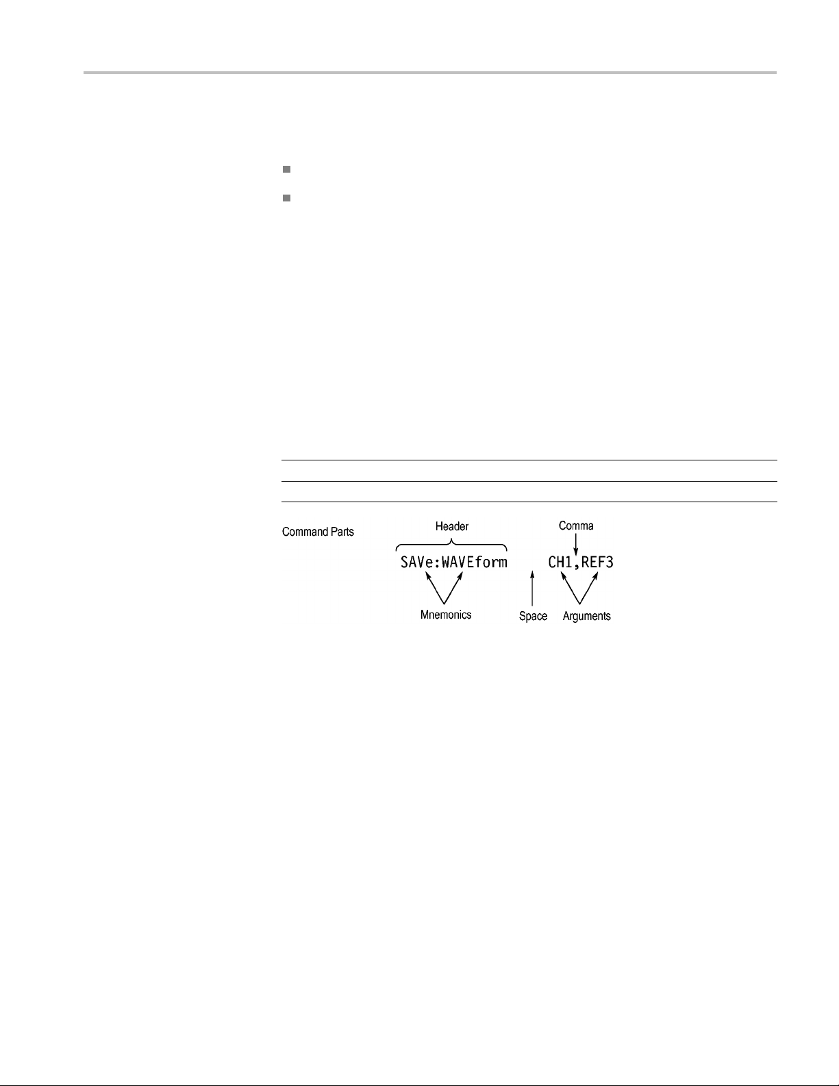
A command message is a command or query name followed by any information
the oscilloscope needs to execute the command or query. Command messages
may c ontain five element type s, defined in the following table.
ACQuire:MODe has a query form ACQuire:MODe?.Notall

Command Syntax
Commands
Table 2-2: Comm
Symbol Meaning
<Header>
<Mnemonic>
<Argument
<Comma> A single c
<Space>
Comman
>
ds cause the oscilloscope to perform a specific function or change one of
and Message Elements
This is the basic command name. If the header ends with a question
mark, the command is a query. The header may begin with a colon
(:) characte
the beginning colon is required. Never use the beginning colon with
command headers beginning with a star (*).
This is a header subfunction. Some command headers have only one
mnemonic. I
character always separates them from each other.
This is a qu
Some commands have no arguments while others have multiple
arguments. A <space> separates arguments from the header. A
<comma> se
commands. Optionally, there may be white space characters before
and after the comma.
A white space character is used between a command header and the
related argument. Optionally, a white space may consist of multiple
white sp
r. If the command is concatenated with other commands,
f a command header has multiple mnemonics, a colon (:)
antity, quality, restriction, or limit associated with the header.
parates arguments from each other.
omma is used between arguments of multiple-argument
ace characters.
the settings. Commands have the structure:
eader>[<Space><Argument>[<Comma> <Argument>]...]
[:]<H
A command header consists of one or more mnemonics arranged in a hierarchical
ee structure. The first mnemonic is the base or root of the tree and each
or tr
subsequent mnemonic is a level or branch off the previous one. Commands at a
higher level in the tree may affect those at a lower level. The leading colon (:)
always returns you to the base of the command tree.
2-2 DPO2000 and MSO2000 Series Programmer Manual
Command Syntax
Queries
Headers
Queries cause t
he oscilloscope to return status or setting information. Queries
have the structure:
[:]<Header>
[:]<Header>[<Space><Argument> [<Coma><Argument>]...]
You can specify a query command at any level within the command tree unless
otherwise noted. These branch queries return information about all the mnemonics
below the sp
ecified branch or level.
Use the HEADer command to control whether the oscilloscope returns headers as
part of the query response. If header is on, the query response returns command
headers,
then formats itself as a valid set command. When header is off, the
response includes only the values. This may make it easier to parse and extract the
information from the response. The table below shows the difference in responses.
Table 2-3: Comparison of Header Off and Header On Responses
Query Header Off Header On
TIME?
ACQuire:NUMAVg?
14:30:00 :TIME “14:30:00”
100
:ACQUIRE:NUMAVG 100
DPO2000 and MSO2000 Series Programmer Manual 2-3

Command Syntax
Clearing the o
scilloscope
Command Entry
Abbrev
iating
You can clear the Output Queue and reset the oscilloscope to accept a new
command or query by using the selected Device Clear (DCL) function.
The following rules apply when entering commands:
You can enter c ommands in upper or lower case.
You can precede any command with white s pace characters. White space
characters include any combination of the ASCII control characters 00 through
09 and 0B through 20 hexadecimal (0 through 9 and 11 through 32 decimal).
The oscilloscope ignores commands consisting of a ny combination of white
space characters and line feeds.
You can abbreviate many oscilloscope commands. Each command in this
documentation shows the minimum acceptable abbreviations in capitals. For
example, you can enter the command ACQuire:NUMAvg simply as ACQ:NUMA
:numa.
or acq
Concatenating
Abbreviation rules may change over time as new oscilloscope models are
oduced. Thus, for the most robust code, use the full spelling.
intr
If you use the HEADer command to have command headers included as part
uery responses, you can further control whether the returned headers are
of q
abbreviated or are full-length with the VERBose command.
You can concatenate any combination of set commands and queries using a
micolon (;). The oscilloscope executes concatenated commands in the order
se
received.
2-4 DPO2000 and MSO2000 Series Programmer Manual

Command Syntax
When concatena
ting commands and queries, you must follow these rules:
1. Separate completely different headers by a semicolon and by the beginning
colon on all commands except the first one. For example, the commands
TRIGger:MODe NORMal and ACQuire:NUMAVg 8, can be concatenated
into the following single command:
TRIGger:MODe NORMal;:ACQuire:NUMAVg 8
2. If concatenated commands have headers that differ by only the last mnemonic,
you can abbreviate the second command and eliminate the beginning colon.
For example, you can concatenate the commands
ACQuire:MODe AVErage
and ACQuire:NUMAVg 8 into a single command:
ACQuire:MODe AVErage; NUMAVg 8
The longer version works equally well:
ACQuire:MODe AVErage;:ACQuire:NUMAVg 8
3. Never precede a star (*) command with a colon:
ACQuire:STATE 1;*OPC
Any commands that follow will be processed as if the star command was
not there so the commands,
ACQuire:MODe ENVelope;*OPC;NUMAVg 8
will set the acquisition mode to envelope and set the number of acquisitions
for averaging to 8.
Terminating
4. When you concatenate queries, the responses to all the queries are
concatenated into a single response message.
5. Set commands and queries may be concatenated in the same message. For
example,
ACQuire:MODe SAMple;NUMAVg?;STATE?
is a valid message that sets the acquisition mode to sample. The message then
queries the number of acquisitions for averaging and the acquisition state.
Concatenated comma nds and queries are executed in the order received.
Here are some invalid concatenations:
HORizontal:SCAle 400E-9;ACQuire:NUMAVg 8 (no colon before
ACQuire)
DISPlay:GRAticule FULL;:*TRG (colon before a star (*) command)
MATH:HORizontal:SCAle 1.0e-1;HORizontal:POSition 5.0el
(levels of the mnemonics are different; either remove the second use of
HORizontal: or place :MATH in front of HORizontal:POSition)
This documentation uses <EOM> (End of Message) to represent a message
terminator.
DPO2000 and MSO2000 Series Programmer Manual 2-5

Command Syntax
Table 2-4: End o
Symbol Meaning
<EOM>
The end-of-message terminator must be the END message (EOI asserted
concurrently with the last data byte). The last data byte may be an ASCII line
feed (LF) character.
This oscilloscope does not support ASCII LF only message termination. The
oscilloscope always terminates outgoing messages with LF and EOI.
Constructed Mnemonics
Some header mnemonics specify one of a range of mnemonics. For example, a
channel
in the command just as you do any other mnemonic. For example, there is a
CH1:POSition command, and there is also a CH2:POSition command. In the
command descriptions, this list of choices is abbreviated as CH<x>.
Cursor Position
Mnemonics
When cursors are displayed, commands may specify which cursor of the pair to
use.
f Message Terminator
Message termi
nator
mnemonic can be CH1, CH2, CH3, or CH4. You use these mnemonics
Math Specifier Mnemonics
Table 2-5: Channel Mnemonics
Symbol Meaning
CH<x> A channel specifier; <x> is 1 through 4.
Table 2-6: Cursor Mnemonics
Symbol Meaning
CURSOR<x>
POSITION<x>
HPOS<x>
A cursor selector; <x> is either 1 or 2.
A cursor selector; <x> is either 1 or 2.
A cursor selector; <x> is either 1 or 2.
Commands can specify the mathematical waveform to use as a mnemonic in
the header.
Table 2-7: Math Specifier Mnemonics
Symbol Meaning
Math<x>
A math waveform specifier; <x> is 1.
2-6 DPO2000 and MSO2000 Series Programmer Manual

Command Syntax
Measurement Specifier
Mnemonics
Channel Mnemonics
Reference Waveform
Mnemonics
Commands can sp
ecify which measurement to set or query as a mnemonic in the
header. Up to four automated measurements may be displayed.
Table 2-8: Measurement Specifier Mnemonics
Symbol Meaning
MEAS<x> A measurement specifier; <x> is 1 through 4.
Commands specify the channel to use as a mnemonic in the header.
Commands can specify the reference waveform to use as a mnemonic in the
header.
Table 2-9: Re f erence Waveform Mnemonics
Symbol Meaning
REF<x>
A reference waveform specifier; <x> 1 or 2. The DPO/MSO2000 series
provides only two REF waveforms regardless of whether the instrument
is a 2 or 4 channel model.
Argument Types
Numeric
Quoted String
ny oscilloscope commands require numeric arguments. The syntax shows
Ma
the format that the oscilloscope returns in response to a query. This is also the
preferred format when sending the command to the oscilloscope though any of
the formats will be accepted. This documentation represents these arguments as
described below.
Table 2-10: Numeric Arguments
Symbol Meaning
<NR1>
<NR2> Floating point value without an exponent
<NR3> Floating point value with an exponent
<bin>
Most num
eric arguments will be automatically forced to a valid setting, by either
Signed integer value
Digital data in binary format
rounding or truncating,, when an invalid number is input, unless otherwise noted
in the command description.
Some commands accept or return data in the form of a quoted string, which is
simply a group of ASCII characters enclosed by a single quote (’) or double quote
("). The following is an example of a quoted string:
string"
. This documentation represents these arguments as follows:
"This is a quoted
DPO2000 and MSO2000 Series Programmer Manual 2-7

Command Syntax
Table 2-11: Quo
Symbol Meaning
<QString> Quoted string of AS CII text
ted String Argument
A quoted string can include any character defined in the 7-bit ASCII character
set. Follow these rules when you use quoted strings:
1. Use the same type of quote character to open and close the string. For
example:
"this is a valid string".
2. You can mix q uotation marks within a string as long as you follow the
previous rule. For example:
"this is an ’acceptable’ string".
3. You can include a quote character within a string by repeating the quote. For
example:
"here is a "" mark".
4. Strings can have upper or lower case characters.
5. If you use a GPIB network, you cannot terminate a quoted string with the
END message before the closing delimiter.
6. A carriage return or line feed embedded in a quoted string does not terminate
the string. The return is treated as another character in the string.
7. The maximum length of a quoted string returned from a query is 1000
characters.
Block
Here are some invalid strings:
"Invalid string argument’ (quotes are not of the same type)
st<EOI>"
"te
(termination character is embedded in the string)
Several oscilloscope commands use a block argument form, as defined in the
table below.
able 2-12: Block Argument
T
Symbol Meaning
NZDig>
<
<Dig>
<DChar> A character with the hexadecimal equivalent of 00 through FF (0
<Block>
A nonzero digit character in the range of 1–9
A digit character, in the range of 0–9
through 255 decimal)
A block of data bytes defined as: <Block> ::=
{#<NZDig><Dig>[<Dig>...][<DChar>...] |#0[<DChar>...]<terminator>}
<NZDig> specifies the number of <Dig> elements that follow. Taken together,
the <NZDig> and <Dig> elements form a decimal integer that specifies how
many <DChar> elements follow.
2-8 DPO2000 and MSO2000 Series Programmer Manual

Command Syntax
DPO2000 and MSO2000 Series Programmer Manual 2-9

Command Syntax
2-10 DPO2000 and MSO2000 Series Programmer Manual

Command Groups
This manual lists the DPO/MSO2000 series IEEE488.2 commands in two ways.
First, it presents them by functional groups. Then, it lists them alphabetically. The
functional g
command. (See page 2-57, Commands Listed in Alphabetical Order.)
Acquisition Command Group
Use the commands in the Acquisition Command Group to set up the modes and
functions that control how the oscilloscope acquires signals input to the channels,
and processes them into waveforms.
Using the commands in this group, you can do the following:
Start and stop acquisitions.
roup list starts below. The alphabetical list provides detail on each
Control
acquisitions of that waveform.
Set the
Control acquisition of channel waveforms.
Set acquisition parameters.
Table 2-13: Acquisition Commands
Command Description
ACQuire?
ACQuire:MAXSamplerate?
ACQuire:MODe Sets or returns the acquisition mode
ACQuire:NUMACq? Returns number of acquisitions that have
ACQuire:NUMAVg Sets or returns the number of acquisitions for
ACQuire:STATE Starts or stops the acquisition system
ACQuire:STOPAfter Sets or returns whether the acquisition is
whether each waveform is simply acquired, averaged over successive
controls or conditions that start and stop acquisitions.
Returns acquisition parameters
Returns the maximum real-time sample rate
occurred
an averaged waveform
continuous or single sequence
DPO2000 and MSO2000 Series Programmer Manual 2-11

Command Groups
Alias Command
Group
Use the Alias commands to define new commands as a sequence of standard
commands. You may find this useful when repeatedly using the same commands
to perform ce
rtain tasks like setting up measurements.
Aliases are similar to macros but do not include the capability to substitute
parameters
into alias bodies. The alias mechanism obeys the following rules:
The alias name must consist of a valid IEEE488.2 message unit, which may
not appear
in a message preceded by a colon, comma, or a command or query
program header.
The a lias
name may not appear in a message followed by a colon, comma,
or question mark.
An alias
name must be distinct from any keyword or keyword short form.
An alias name cannot be redefined without first b eing deleted using one of
as deletion functions.
the ali
Alias names do not appear in response messages.
2-14: Alias Commands
Table
Command Description
s
ALIa
ALIas:CATalog? Returns a list of the currently defined alias
ALIas:DEFine
ALIas:DELEte
ALIas:DELEte:ALL Deletes all existing aliases
ALIas:DELEte[:NAMe]
ALIas[:STATE ] Sets or returns the alias state
Sets or returns the alias state
labels
Assigns a sequence of program messages
n alias label
to a
moves a specified alias
Re
Removes a specified alias
2-12 DPO2000 and MSO2000 Series Programmer Manual

Command Groups
Bus Command Gr
oup
Use the Bus commands when working with serial bus measurements.
Install the DPO2EMBD application module when working with I2CorSPI
bus signals.
Install the DPO2AUTO module when working with CAN or LIN bus signals.
Install the DPO2COMP module when working with RS232 bus signals.
Table2-15: BusCommands
Commands Description
BUS Returns the parameters for each bus
BUS:B<x>:CAN:BITRate Sets or returns the bit rate for the CAN bus
BUS:B<x>:CAN:PRObe Sets or returns the probing method used to
probe the CA N bus
BUS:B<x>:CAN:SAMPLEpoint Sets or returns the sample point (in %) to
sample during each bit period
BUS:B<x>:CAN:SOUrce Sets or returns the CAN data source
BUS:B<x>:DISplay:FORMAt Sets the display format for the numerical
information in the specified bus waveform
BUS:B<x>:I2C:ADDRess:RWINClude Sets and returns whether the read/write bit is
included in the address
BUS:B<x>:I2C{:CLOCK|:SCLK}:SOUrce Sets or returns the I2C SCLK source
BUS:B<x>:I2C{:DATA|:SDATA}:SOUrce Sets or returns the I2C SDATA source
BUS:B<x>:LABel Sets or returns the waveform label for the
specified bus
BUS:B<x>:LIN:BITRate Sets or returns the bit rate for LIN
BUS:B<x>:LIN:IDFORmat Sets or returns the LIN ID format
BUS:B<x>:LIN:POLARity Sets or returns the LIN polarity
BUS:B<x>:LIN:SAMPLEpoint Sets or returns the sample point (in %) at
which to sample during each bit period
BUS:B<x>:LIN:SOUrce Sets or returns the LIN data source
BUS:B<x>:LIN:STANDard Sets or returns the LIN standard
BUS:B<x>:PARallel:BIT<x>:SOUrce Sets or returns the parallel bit <x> source
BUS:B<x>:PARallel:CLOCK:EDGE Sets or returns the parallel clock edge for
bus <x>
BUS:B<x>:PARallel:CLOCK:ISCLOCKed Sets or returns whether the parallel bus is
clocked
BUS:B<x>:PARallel:CLOCK:SOUrce Sets or returns the parallel bus<x> clock
source
BUS:B<x>:PARallel:WIDth Sets or returns the number of bits used for
the width of the parallel bus <x>
DPO2000 and MSO2000 Series Programmer Manual 2-13

Command Groups
Table2-15: BusCommands(cont.)
Commands Description
BUS:B<x>:POSition Sets or returns the position of the specified
bus waveform
BUS:B<x>:RS232C:BITRate Sets or returns the RS232 bit rate for the
specified bus
BUS:B<x>:RS232C:DATABits Sets or returns the number of bits for the
data frame
BUS:B<x>:RS232C:DELIMiter Sets or returns the RS232 delimiting value
for a packet on the specified bus
BUS:B<x>:RS232C:DISplaymode Sets or returns the display mode for the
specified bus display and event table
BUS:B<x>:RS232C:PARity Sets or returns parity for RS232 data
BUS:B<x>:RS232C:POLarity Sets or returns the RS232C polarity for the
specified bus
BUS:B<x>:RS232C:RX:SOUrce Sets or returns the RS232 RX source
BUS:B<x>:RS232C:TX:SOUrce Sets or returns the RS232 TX Source
BUS:B<x>:SPI{:CLOCK|:SCLK}:POLARity Sets or returns the SPI SCLK polarity
BUS:B<x>:SPI{:CLOCK|:SCLK}:SOUrce Sets or returns the SPI SCLK source
BUS:B<x>:SPI:DATA{:IN|:MISO}:POLARity Sets or returns the SPI MISO polarity
BUS:B<x>:SPI:DATA{:IN|:MISO}:SOUrce Sets or returns the SPI MISO source
BUS:B<x>:SPI:DATA{:OUT|:MOSI}:
POLARity
BUS:B<x>:SPI:DATA{:OUT|:MOSI}:SOUrce Sets or returns the SPI MOSI source
BUS:B<x>:SPI{:SELect|:SS}:POLARity Sets or returns the SPI SS polarity
BUS:B<x>:SPI{:SELect|:SS}:SOUrce Sets or returns the SPI SS source
BUS:B<x>:SPI:BITOrder Sets or returns the bit order for the specified
BUS:B<x>:SPI:DATA:SIZe Sets or returns the number of bits per word
BUS:B<x>:SPI:FRAMING Sets or returns the type of SPI framing
BUS:B<x>:SPI:IDLETime Sets or r eturns the SPI bus idle time in
BUS:B<x>:STATE Turns the specified bus on and off
BUS:B<x>:TYPE Sets or returns the specified bus type
BUS:LOWerthreshold:CH<x> Sets or returns the lower threshold for each
BUS:THReshold:CH<x> Sets or returns the threshold for a channel
BUS:UPPerthreshold:CH<x> Sets or returns the upper threshold for each
BUS:THReshold:D<x> Sets or returns the threshold for digital
Sets or returns the SPI MOSI polarity
SPI bus
for the specified SPI bus
seconds for the specified SPI bus
channel
channel
channel
2-14 DPO2000 and MSO2000 Series Programmer Manual

Command Groups
Table 2-15: Bus Commands (cont.)
Commands Description
SEARCH:SEARCH<x>:TRIGger:A:BUS?
SEARCH:SEARCH<x>:TRIGger:A:BUS:
B<x>:LIN:CONDition
SEARCH:SEARCH<x>:TRIGger:A:BUS:
B<x>:LIN:DATa:HIVALue
SEARCH:SEARCH<x>:TRIGger:A:BUS:
B<x>:LIN:DATa:QUALifier
SEARCH:SEARCH<x>:TRIGger:A:BUS:
B<x>:LIN:DATa:SIZe
SEARCH:SEARCH<x>:TRIGger:A:BUS:
B<x>:LIN:DATa:VALue
SEARCH:SEARCH<x>:TRIGger:A:BUS:
B<x>:LIN:ERRTYPE
SEARCH:SEARCH<x>:TRIGger:A:BUS:
B<x>:LIN:IDentifier:VALue
SEARCH:SEARCH<x>:TRIGger:A:BUS:
B<x>:RS232C:CONDition
SEARCH:SEARCH<x>:TRIGger:A:BUS:
B<x>:RS232C:RX:DATa:SIZe
SEARCH:SEARCH<x>:TRIGger:A:BUS:
B<x>:RS232C:RX:DATa:VALue
TRIGger:A:BUS:B<x>:LIN:CONDition Sets or returns the trigger condition for LIN
TRIGger:A:BUS:B<x>:LIN:DATa:HIVALue Sets or returns the binary data string to be
TRIGger:A:BUS:B<x>:LIN:DATa:QUALifier Sets or returns the LIN data quali fier
TRIGger:A:BUS:B<x>:LIN:DATa:SIZe Sets or returns the length of the data string
TRIGger:A:BUS:B<x>:LIN:DATa:VALue Sets or returns the binary data string
TRIGger:A:BUS:B<x>:LIN:ERRTYPE Sets or returns the error type
TRIGger:A:BUS:B<x>:LIN:IDentifier:VALue Sets or returns the binary address string
TRIGger:A:BUS:B<x>:RS232C:RX:DATa:
SIZe
TRIGger:A:BUS:B<x>:RS232C:RX:DATa:
VALue
TRIGger:A:BUS:B<x>:RS232C:TX:DATa:
SIZe
TRIGger:A:BUS:B<x>:RS232C:TX:DATa:
VALue
Returns the serial search type
Sets or returns the search condition for a LIN
search
Sets or returns the binary data string
Sets or returns the LIN data quali fier
Sets or returns the length of the data string
in bytes
Sets or returns the binary data string used
for a LIN search
Sets or returns the error type used for a LIN
Search
Sets or returns the binary address string
used for LIN search
Sets or returns the trigger condition for a
RS232 trigger
Sets or returns the length of the data string
for a RS232 RX trigger
Sets or returns the binary data string for a
RX RS232 trigger
used for LIN trigger
in bytes to be used for LIN trigger
used for LIN trigger
Sets or returns the length of the data string
for a RX RS232 trigger
Sets or returns the binary data string for a
RX RS232 trigger
Sets or returns the length of the data string
to be used for a TX RS232 Trigger
Sets or returns the binary data string to be
used for a TX RS232 trigger
DPO2000 and MSO2000 Series Programmer Manual 2-15

Command Groups
Calibration a
nd Diagnostic Command Group
The Calibration and Diagnostic commands provide i nformation about the current
state of oscilloscope calibration. They also initiate internal signal path calibration
(SPC)orexec
calibration are not described in this manual. They are described in the Service
manual, located on the DPO2000 Documentation CD-ROM in PDF format. You
can also order a printed copy.
Table 2-16: Calibration and Diagnostic Commands
Command
*CAL? Instruct
CALibrate:FACtory Provides the controls for starting and
ate:FACtory:STATus?
CALibr
CALibrate:INTERNal Starts a signal path compensation
CALibrate:INTERNal:STARt Starts the internal signal path calibration
CALibrate:INTERNal:STATus? Returns the current status of the internal
CALibrate:RESults? Returns the status of all calibration
CALibrate:RESults:FACtory? Returns the status of internal and factory
CALibrate:RESults:SPC? Returns the results of the last SPC operation
CALibrate:TEMPerature? Returns 0 as DPO/MSO2000 series does
DIAg:LOOP:OPTion Sets the self-test loop option
DIAg:LOOP:OPTion:NTIMes Sets the self-test loop option to run N times
DIAg:LOOP:STOP Stops the self-test at the end of the current
DIAg:RESUlt:FLAg? Returns the pass/fail status from the last
DIAg:RESUlt:LOG? Returns the internal results log from the last
DIAg:SELect:<function> Selects one of the available s elf-test areas
DIAg:STATE Sets the oscilloscope operating state
DIAg:SELect Runs self tests on the specified system
ute diagnostic tests. Commands that are specifictofactory
Description
s the oscilloscope to perform
self-calibration and returns the oscilloscope
self calibration status
g the factory calibration process
stoppin
s the factory calibration status value
Return
saved in nonvolatile memory
signal path calibration
systems without performing an SPC
sub
operation
calibration
ot support recording of oscilloscope
n
temperature
loop
self-test sequence execution
self-test sequence execution
subsystem
2-16 DPO2000 and MSO2000 Series Programmer Manual

Command Groups
Cursor Comman
dGroup
Use the commands in the Cursor Command Group to control the cursor display
and readout. You can use these commands to control the setups for cursor 1 and
cursor 2, suc
You can also use the commands to select one of the following cursor functions:
Table 2-17: Cursor Commands
Command
CURSor?
CURSor:FUNCtion Sets or returns the cursor type
CURSor:HBArs?
CURSor:HBArs:DELTa? Returns hbars cursors vertical difference
CURSor:HBArs:POSITION<x> Sets or returns the hbar cursor<x> vertical
CURSor:HBArs:UNIts
CURSor:HBArs:USE Sets the horizontal bar cursor measurement
CURSor:MODe Sets or returns whether cursors move in
CURSor:VBArs? Sets or returns the position of vertical bar
CURSor:VBArs:ALTERNATE<x>? Returns the alternate readout for the
CURSor:VBArs:DELTa? Returns the difference between vbar cursors
CURSor:VBArs:HPOS<x>? Returns the horizontal value of the specified
CURSor:VBArs:POSITION<x> Sets or returns the vbar cursor<x> horizontal
CURSor:VBArs:UNIts Sets or returns the units for vbar cursors
CURSor:VBArs:USE Sets the vertical bar cursor measurement
CURSor:VBArs:VDELTa? Returns the vertical difference between the
CURSor:XY:POLar:RADIUS:DELta? Returns the difference between the cursors
h as cursor position.
Off. Turns off the display of all cursors.
Waveform Cursors. Consists of two cursors. Waveform cursors enable you to
conveniently measure waveform amplitude and time.
Screen Cursors. Consists of two pairs of independent horizontal and vertical
cursors. You can use these cursors to indicate an arbitrary position within
the waveform display area.
Description
Returns cursor settings
Returns hbar cursor settings
position
Returns hbar cursor units
scale
unison or separately
cursors
waveform (Vbar) cursors
vertical bar ticks
position
scale
two vertical bar cursor ticks
X radius and the c ursor Y radius
DPO2000 and MSO2000 Series Programmer Manual 2-17

Command Groups
Table 2-17: Cursor Commands (cont.)
Command
CURSor:XY:POLar:RADIUS:POSITION<x>? Returns the polar radius of the specified
CURSor:XY:POLar:RADIUS:UNIts?
CURSor:XY:POLar:THETA:DELta?
CURSor:XY:POLar:THETA:POSITION<x>?
CURSor:XY:POLar:THETA:UNIts?
CURSor:XY:PRODUCT:DELta? Returns the difference between the cursors
CURSor:XY:PRODUCT:POSITION<x>? Returns the position of the X or Y cursor used
CURSor:XY:PRODUCT:UNIts?
CURSor:XY:RATIO:DELta? Returns the ratio of the difference between
CURSor:XY:RATIO:POSITION<x>? Returns the X or Y position for the specified
CURSor:XY:RATIO:UNIts? Returns the X and Y cursor units for the ratio
CURSor:XY:RECTangular:X:DELta?
CURSor:XY:RECTangular:X:POSITION<x> Sets or returns the cursor X rectangular
CURSor:XY:RECTangular:X:UNIts? Returns the Cursor X rectangular units
CURSor:XY:RECTangular:Y:DELta?
CURSor:XY:RECTangular:Y:POSITION<x>> Sets or returns the cursor Y rectangular
CURSor:XY:RECTangular:Y:UNIts?
Description
cursor
Returns the polar radius units
Returns the XY cursor polar coordinate delta
Returns the cursor X or cursor Y polar
coordinate
Returns the cursor polar coordinate units
X position and cursor Y position
to calculate the X × Y cursor measurement
Returns the XY cursor product units
the cursor X position and cursor Y position
cursor
measurement
Returns the cursor X delta value in
rectangular coordinates
coordinates
Returns The cursor Y delta value in
rectangular coordinates
coordinates
Returns the cursor Y rectangular units
Display Command Group
Use the commands in the Display Command Group to change the graticule style,
the displayed intensities, and to set the c haracteristics of the waveform display.
Use these commands to set the style that best displays your waveforms and
graticule display properties. Note that the mode you choose globally affects all
displayed waveforms.
Table 2-18: Display Commands
Command
DISplay?
2-18 DPO2000 and MSO2000 Series Programmer Manual
Description
Returns current display settings

Table 2-18: Display Commands (cont.)
Command Groups
Command
DISplay:CLOCk Sets or returns the display of the date/time
DISplay:DIGital:HEIght Sets or returns the height of the digital
DISplay:FORMat Sets or returns the display format
DISplay:GRAticule Sets or returns the type of graticule that is
DISplay:INTENSITy?
DISplay:INTENSITy:BACKLight Sets or returns the backlight intensity for the
DISplay:INTENSITy:GRAticule Sets or returns the graticule intensity for the
DISplay:INTENSITy:WAVEform Sets or returns the intensity of the waveforms
DISplay:PERSistence Sets or returns display persistence setting
MESSage:BOX Sets or returns the size and position of the
MESSage:CLEAR Removes the message text from the
MESSage:SHOW Clears the contents of the message window
MESSage:STATE Controls the display of the message window
Description
stamp
display and the number of waveforms that
you can display
displayed
Returns all display intensity settings
display
display
message window
message window
Ethernet Command Group
Use the commands in the Ethernet Command Group to set up the Ethernet remote
interface.
Table 2-19: Ethernet Commands
Command
ETHERnet:DHCPbootp Sets or returns the network initialization
ETHERnet:DNS:IPADDress Sets or returns the network Domain Name
ETHERnet:DOMAINname Sets or returns the network domain name
ETHERnet:ENET:ADDress?
ETHERnet:GATEWay:IPADDress Sets or returns the remote interface gateway
ETHERnet:HTTPPort
Description
search for a DHCP/BOOTP server
Server (Dns) IP address
Returns the Ethernet address value assigned
to the oscillosc ope
IP address
Sets or returns the remote interface HTTP
port value
DPO2000 and MSO2000 Series Programmer Manual 2-19

Command Groups
Table 2-19: Ethernet Commands (cont.)
Command
ETHERnet:IPADDress
ETHERnet:NAME
ETHERnet:PASSWord Sets or returns the Ethernet access password
ETHERnet:PING Causes the oscilloscope to ping the gateway
ETHERnet:PING:STATUS? Returns the results from pinging the gateway
ETHERnet:SUBNETMask Sets or returns the remote interface subnet
File System Command Group
Use the commands in the File System Command Group to access USB media.
an use the commands to do the following:
You c
List the contents of a directory
Create, rename and delete directories
Description
Sets or returns the IP address assigned to
the oscilloscope
Sets or returns the network name assigned
to the o scillos cope
IP address
IP address
mask value
Create,read,rename,ordeleteafile
Format media
When using these commands, keep the following points in mind:
ile arguments are always enclosed within double quotes:
F
"E:/MYDIR/TEK00001.SET"
ile names follow the non-case sensitive, MSDOS format:
F
[DRIVE:][\PATH\]filename
File names for commands and queries are not case sensitive. Save commands
translate all file names to uppercase for storage
For Example: SAVE:WAVEFORM CH1,"ch1.isf" results in Ch1 being saved
to a file named CH1.ISF.
RECALL:WAVEFORM "Ch1.isf",REF1 would recall the waveform from the
file CH1.ISF to the REF1 internal waveform storage location.
Path separators may be either forward slashes (/) or back slashes (\)
The file and directory names have no more than eight characters as the base
name, and no more than three characters as the extension as in 8.3 format
2-20 DPO2000 and MSO2000 Series Programmer Manual
 Loading...