

Page 1

Model DMM6500
6½-Digit Multimeter with Scanning
Calibration and Adjustment Manual
DMM6500-905-01 Rev. E June 2022
tek.com/keithley
*DMM6500-905-01E*
DMM6500-905-01E
Page 2

6½-Digit Multimeter with Scanning
DMM6500
Calibration and Adjustment Manual
Page 3

© 2022, Keithley Instruments, LLC
Cleveland, Ohio, U.S.A.
All rights reserved.
Any unauthorized reproduction, photocopy, or use of the information herein, in whole or in part,
without the prior written approval of Keithley Instruments, LLC, is strictly prohibited.
These are the original instructions in English.
TSPTM and TSP-LinkTM are trademarks of Keithley Instruments, LLC. All Keithley Instruments
product names are trademarks or registered trademarks of Keithley Instruments, LLC. Other brand
names are trademarks or registered trademarks of their respective holders.
The Lua 5.0 software and associated documentation files are copyright © 1994-2008, Tecgraf,
PUC-Rio. Terms of license for the Lua software and associated documentation can be accessed at
the Lua licensing site (http://www.lua.org/license.html).
Microsoft, Visual C++, Excel, and Windows are either registered trademarks or trademarks of
Microsoft Corporation in the United States and/or other countries.
Document number: DMM6500-905-01 Rev. E June 2022
Page 4

Safety precautions
The following safety precautions should be observed before using this product and any associated instrumentation. Although
some instruments and accessories would normally be used with nonhazardous voltages, there are situations where hazardous
conditions may be present.
This product is intended for use by personnel who recognize shock hazards and are familiar with the safety precautions required
to avoid possible injury. Read and follow all installation, operation, and maintenance information carefully before using the
product. Refer to the user documentation for complete product specifications.
If the product is used in a manner not specified, the protection provided by the product warranty may be impaired.
The types of product users are:
Responsible body is the individual or group responsible for the use and maintenance of equipment, for ensuring that the
equipment is operated within its specifications and operating limits, and for ensuring that operators are adequately trained.
Operators use the product for its intended function. They must be trained in electrical safety procedures and proper use of the
instrument. They must be protected from electric shock and contact with hazardous live circuits.
Maintenance personnel perform routine procedures on the product to keep it operating properly, for example, setting the line
voltage or replacing consumable materials. Maintenance procedures are described in the user documentation. The procedures
explicitly state if the operator may perform them. Otherwise, they should be performed only by service personnel.
Service personnel are trained to work on live circuits, perform safe installations, and repair products. Only properly trained
service personnel may perform installation and service procedures.
Keithley products are designed for use with electrical signals that are measurement, control, and data I/O connections, with low
transient overvoltages, and must not be directly connected to mains voltage or to voltage sources with high transient
overvoltages. Measurement Category II (as referenced in IEC 60664) connections require protection for high transient
overvoltages often associated with local AC mains connections. Certain Keithley measuring instruments may be connected to
mains. These instruments will be marked as category II or higher.
Unless explicitly allowed in the specifications, operating manual, and instrument labels, do not connect any instrument to mains.
Exercise extreme caution when a shock hazard is present. Lethal voltage may be present on cable connector jacks or test
fixtures. The American National Standards Institute (ANSI) states that a shock hazard exists when voltage levels greater than
30 V RMS, 42.4 V peak, or 60 VDC are present. A good safety practice is to expect that hazardous voltage is present in any
unknown circuit before measuring.
Operators of this product must be protected from electric shock at all times. The responsible body must ensure that operators
are prevented access and/or insulated from every connection point. In some cases, connections must be exposed to potential
human contact. Product operators in these circumstances must be trained to protect themselves from the risk of electric shock. If
the circuit is capable of operating at or above 1000 V, no conductive part of the circuit may be exposed.
Do not connect switching cards directly to unlimited power circuits. They are intended to be used with impedance-limited
sources. NEVER connect switching cards directly to AC mains. When connecting sources to switching cards, install protective
devices to limit fault current and voltage to the card.
Before operating an instrument, ensure that the line cord is connected to a properly-grounded power receptacle. Inspect the
connecting cables, test leads, and jumpers for possible wear, cracks, or breaks before each use.
When installing equipment where access to the main power cord is restricted, such as rack mounting, a separate main input
power disconnect device must be provided in close proximity to the equipment and within easy reach of the operator.
For maximum safety, do not touch the product, test cables, or any other instruments while power is applied to the circuit under
test. ALWAYS remove power from the entire test system and discharge any capacitors before connecting or disconnecting
cables or jumpers, installing or removing switching cards, or making internal changes, such as installing or removing jumpers.
Do not touch any object that could provide a current path to the common side of the circuit under test or power line (earth)
ground. Always make measurements with dry hands while standing on a dry, insulated surface capable of withstanding the
voltage being measured.
Page 5
For safety, instruments and accessories must be used in accordance with the operating instructions. If the instruments or
accessories are used in a manner not specified in the operating instructions, the protection provided by the equipment may be
impaired.
Do not exceed the maximum signal levels of the instruments and accessories. Maximum signal levels are defined in the
specifications and operating information and shown on the instrument panels, test fixture panels, and switching cards.
When fuses are used in a product, replace with the same type and rating for continued protection against fire hazard.
Chassis connections must only be used as shield connections for measuring circuits, NOT as protective earth (safety ground)
connections.
If you are using a test fixture, keep the lid closed while power is applied to the device under test. Safe operation requires the use
of a lid interlock.
screw is present, connect it to protective earth (safety ground) using the wire recommended in the user documentation.
If a
The
symbol on an instrument means caution, risk of hazard. The user must refer to the operating instructions located in the
user documentation in all cases where the symbol is marked on the instrument.
The
symbol on an instrument means warning, risk of electric shock. Use standard safety precautions to avoid personal
contact with these voltages.
The
The
If this
symbol on an instrument shows that the surface may be hot. Avoid personal contact to prevent burns.
symbol indicates a connection terminal to the equipment frame.
symbol is on a product, it indicates that mercury is present in the display lamp. Please note that the lamp must be
properly disposed of according to federal, state, and local laws.
The WARNING heading in the user documentation explains hazards that might result in personal injury or death. Always read
the associated information very carefully before performing the indicated procedure.
The CAUTION heading in the user documentation explains hazards that could damage the instrument. Such damage may
invalidate the warranty.
The CAUTION heading with the
symbol in the user documentation explains hazards that could result in moderate or minor
injury or damage the instrument. Always read the associated information very carefully before performing the indicated
procedure. Damage to the instrument may invalidate the warranty.
Instrumentation and accessories shall not be connected to humans.
Before performing any maintenance, disconnect the line cord and all test cables.
To maintain protection from electric shock and fire, replacement components in mains circuits — including the power
transformer, test leads, and input jacks — must be purchased from Keithley. Standard fuses with applicable national safety
approvals may be used if the rating and type are the same. The detachable mains power cord provided with the instrument may
only be replaced with a similarly rated power cord. Other components that are not safety-related may be purchased from other
suppliers as long as they are equivalent to the original component (note that selected parts should be purchased only through
Keithley to maintain accuracy and functionality of the product). If you are unsure about the applicability of a replacement
component, call a Keithley office for information.
Unless otherwise noted in product-specific literature, Keithley instruments are designed to operate indoors only, in the following
environment: Altitude at or below 2,000 m (6,562 ft); temperature 0 °C to 50 °C (32 °F to 122 °F); and pollution degree 1 or 2.
To clean an instrument, use a cloth dampened with deionized water or mild, water-based cleaner. Clean the exterior of the
instrument only. Do not apply cleaner directly to the instrument or allow liquids to enter or spill on the instrument. Products that
consist of a circuit board with no case or chassis (e.g., a data acquisition board for installation into a computer) should never
require cleaning if handled according to instructions. If the board becomes contaminated and operation is affected, the board
should be returned to the factory for proper cleaning/servicing.
Safety precaution revision as of June 2018.
Page 6

Table of contents
Introduction ............................................................................................................... 1-1
Welcome .............................................................................................................................. 1-1
Introduction to this manual ................................................................................................... 1-1
Extended warranty ............................................................................................................... 1-2
Contact information .............................................................................................................. 1-2
Performance verification .......................................................................................... 2-1
Introduction .......................................................................................................................... 2-1
Verification test requirements .............................................................................................. 2-2
Environmental conditions .......................................................................................................... 2-2
Warmup period .......................................................................................................................... 2-2
Line power................................................................................................................................. 2-3
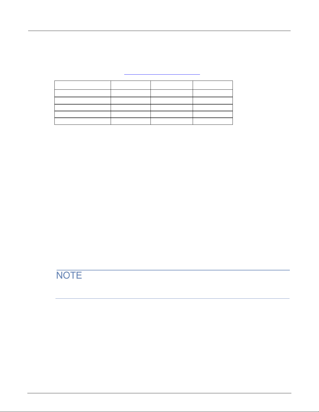
Recommended test equipment ................................................................................................. 2-3
Calibration verification limits ................................................................................................ 2-4
Example reading limit calculation .............................................................................................. 2-4
Calculating resistance reading limits ......................................................................................... 2-4
Performing the verification test procedures ......................................................................... 2-5
Test summary ........................................................................................................................... 2-5
Test considerations ................................................................................................................... 2-6
Front-panel calibration verification ....................................................................................... 2-6
DC voltage verification .............................................................................................................. 2-6
AC voltage verification ............................................................................................................ 2-10
Digitize dc voltage verification ................................................................................................. 2-14
Frequency verification ............................................................................................................. 2-17
Simulated thermocouple type J temperature verification ......................................................... 2-18
Simulated RTD temperature verification ................................................................................. 2-20
Resistance verification ............................................................................................................ 2-24
DC current verification ............................................................................................................. 2-29
Digitize current verification ...................................................................................................... 2-33
AC current verification ............................................................................................................. 2-36
Capacitance verification .......................................................................................................... 2-39
Verifying zero values using a 4-wire short ............................................................................... 2-41
Rear-panel verification ....................................................................................................... 2-43
DC current 10 A range verification .......................................................................................... 2-43
Digitize current 10 A range verification .................................................................................... 2-45
AC current 10 A verification..................................................................................................... 2-47
Adjustment ................................................................................................................ 3-1
Introduction .......................................................................................................................... 3-1
Environmental conditions ..................................................................................................... 3-2
Temperature and relative humidity ............................................................................................ 3-2
Line power................................................................................................................................. 3-2
Warmup period ..................................................................................................................... 3-2
Adjustment overview ............................................................................................................ 3-3
Recommended test equipment ............................................................................................ 3-3
Page 7

Table of contents
Calibration and Adjustment Manual
DMM6500 6½-Digit Multimeter with Scanning
General adjustment considerations ..................................................................................... 3-4
Initial instrument setup ......................................................................................................... 3-5
Select the correct terminals ....................................................................................................... 3-5
Select the TSP command set .................................................................................................... 3-5
Verify instrument date and time ................................................................................................. 3-6
Set up remote connections........................................................................................................ 3-6
Unlock calibration ...................................................................................................................... 3-6
Disable temperature correction ................................................................................................. 3-7
Remote calibration adjustment procedures ......................................................................... 3-7
Disable temperature correction ................................................................................................. 3-7
Front-terminal adjustment with a 4-wire short ........................................................................... 3-7
Rear-terminal adjustment with a 4-wire short .......................................................................... 3-10
Front-terminal adjustment with open circuit inputs .................................................................. 3-13
Rear-terminal adjustment with open circuit inputs ................................................................... 3-14
Resistance adjustment ............................................................................................................ 3-15
DC voltage adjustment ............................................................................................................ 3-18
DC current adjustment ............................................................................................................ 3-20
DC current 10 A range adjustment .......................................................................................... 3-24
AC voltage adjustment ............................................................................................................ 3-26
AC current adjustment ............................................................................................................ 3-29
AC current 10 A range adjustment .......................................................................................... 3-31
Frequency adjustment ............................................................................................................. 3-32
Complete list of calibration commands .................................................................................... 3-34
Enable temperature correction ........................................................................................... 3-46
Save calibration and set the adjustment dates .................................................................. 3-46
Setting time, adjustment, and verification dates ................................................................ 3-47
Adjustment command timing and error checking ............................................................... 3-47
Handling events ................................................................................................................. 3-48
TSP command reference .......................................................................................... 4-1
TSP commands .................................................................................................................... 4-1
Introduction ............................................................................................................................... 4-1
cal.adjust.count ......................................................................................................................... 4-2
cal.adjust.date ........................................................................................................................... 4-3
cal.adjust.step.setup() ............................................................................................................... 4-4
cal.adjust.step.execute() ........................................................................................................... 4-5
cal.lock() .................................................................................................................................... 4-6
cal.password ............................................................................................................................. 4-7
cal.save()................................................................................................................................... 4-8
cal.unlock() ................................................................................................................................ 4-9
cal.verify.date .......................................................................................................................... 4-10
Page 8

In this section:
Contact information .................................................................. 1-2
Welcome
The DMM6500 is a 6½ digit graphical sampling multimeter that expands standard DMM functions with
high-speed digitizing and large graphical color touchscreen display.
This manual provides information on completing verification and adjustment procedures for your
DMM6500.
Section 1
Introduction
Welcome .................................................................................. 1-1
Introduction to this manual ....................................................... 1-1
Extended warranty ................................................................... 1-2
Introduction to this manual
This manual provides instructions to help you calibrate and adjust your DMM6500. In this manual,
calibration refers to the process of verifying that the accuracy of the instrument is within its one-year
accuracy specifications. Also, adjustment refers to the process of changing the calibration constants
so that the accuracy of the instrument is within its one-year accuracy specifications.
This manual presents calibration information, adjustment information, and command descriptions for
the calibration and adjustment commands.
For additional command descriptions, refer to the DMM6500 Reference Manual available on the
Product Support and Downloads web page (tek.com/en/support/product-support). Additionally,
refer to the release notes for your instrument that contains relevant information on
improvements, changes, and known issues.
Page 9

Section
ation and Adjustment Manual
1: Introduction DMM6500 6½-Digit Multimeter with Scanning Calibr
Extended warranty
Additional years of warranty coverage are available on many products. These valuable contracts
protect you from unbudgeted service expenses and provide additional years of protection at a fraction
of the price of a repair. Extended warranties are available on new and existing products. Contact your
local Keithley Instruments office, sales partner, or distributor for details.
Contact information
If you have any questions after you review the information in this documentation, please contact your
local Keithley Instruments office, sales partner, or distributor. You can also call the Tektronix
corporate headquarters (toll-free inside the U.S. and Canada only) at 1-800-833-9200. For worldwide
contact numbers, visit tek.com/contact
.
1-2 DMM6500-905-01 Rev. E June 2022
Page 10

Rear-panel verification ........................................................... 2-43
In this section:
Introduction .............................................................................. 2-1
Verification test requirements ................................................... 2-2
Calibration verification limits ..................................................... 2-4
Performing the verification test procedures .............................. 2-5
Front-panel calibration verification ........................................... 2-6
Introduction
Use the procedures in this section to verify that DMM6500 accuracy is within the limits stated in the
instrument’s one-year accuracy specifications. Specifications and characteristics are subject to
change without notice; refer to the Product Support and Downloads web page
(tek.com/en/support/product-support) for the most recent specifications.
Section 2
Performance verification
You can use these verification procedures to:
• Make sure that the instrument was not damaged during shipment.
• Verify that the instrument meets factory specifications.
• Determine if adjustment is required.
• Verify that adjustment was done properly.
The information in this section is intended for qualified service personnel only, as described
by the types of product users in the Safety precautions pages, provided at the beginning of
this document. Do not attempt these procedures unless you are qualified to do so.
Some of these procedures may expose you to hazardous voltages, that if contacted, could
cause personal injury or death. Use appropriate safety precautions when working with
hazardous voltages.
Page 11

Section
Calibration and Adjustment Manual
2: Performance verification DMM6500 6½-Digit Multimeter with Scanning
If the instrument is still under warranty and its performance is outside specified limits, please contact
your local Keithley Instruments office, sales partner, or distributor. You can also call the Tektronix
corporate headquarters (toll-free inside the U.S. and Canada only) at 1-800-833-9200. For worldwide
contact numbers, visit tek.com/contact
.
Verification test requirements
Be sure that you perform these verification tests:
• Under the proper environmental conditions.
• After the specified warmup period.
• Using the correct line voltage.
• Using the proper test equipment.
• Using the specified output signal and reading limits.
Environmental conditions
Conduct the calibration verification procedures in a test environment with:
• An ambient temperature of 18 °C to 28 °C.
• A relative humidity of less than or equal to 80 percent, unless otherwise noted.
• No direct airflow on the input terminals.
Warmup period
Allow the DMM6500 to warm up for at least 30 minutes before conducting the calibration verification
procedures.
If the instrument has been subjected to temperature extremes (more than 5 °C above or below T
allow additional time for the internal temperature of the instrument to stabilize. Typically, allow an
additional 30 minutes to stabilize an instrument that is 10 °C outside the specified temperature range.
Also allow the test equipment to warm up for the time recommended by the manufacturer.
CAL
),
2-2 DMM6500-905-01 Rev. E June 2022
Page 12

DMM6500
Performance verification
Fluke
5720A or 5730A
High-Performance
DCV, ACV, ACI, and
See following
Fluke
5725A
Amplifier
DCI and ACI
See following
note.
Fluke
8508A or 8588A
8.5-Digit Reference
Multimeter
DCI
See following
note.
Keithley
Instruments
3390
Function/Arbitrary
Waveform Generator
Frequency
See following
note.
IET Labs, Inc.
HACS-Z-A-2E-1uF
Series HACS-Z High
Capacitance Box
Capacitance, 1 µF to
See following
Keithley
Instruments
8610 or 8620
4-Wire DMM Shorting
Plug
DCV, digitize DCV, and
resistance
See following
note.
6½-Digit Multimeter with Scanning Calibration and Adjustment Manual Section 2:
Line power
The DMM6500 requires a line voltage of 100 V to 240 V and a line frequency of 400 Hz, 50 Hz or
60 Hz. Calibration verification tests should be performed within this range.
The instrument automatically senses the line frequency at power-up.
Recommended test equipment
The following table summarizes the recommended calibration verification equipment. You can use
alternate equipment if that equipment has specifications that meet or exceed those listed in the table
below. Test equipment uncertainty adds to the uncertainty of each measurement. Generally, test
equipment uncertainty should be at least four times more accurate than corresponding DMM6500
specifications.
In this manual, the Model 8610 shorting plug is shown in the figures. However, you can use either
the Model 8610 or the Model 8620 shorting plug.
Manufacturer Model Description Used for Uncertainty
Multifunction Calibrator
IET Labs, Inc. 1423-A Precision Decade
Capacitor
Accuracy Decade
resistance
Capacitance, 1 nF to
1 µF
100 µF
note.
See following
note.
note.
Refer to the manufacturer's specifications to calculate the uncertainty, which varies for each function
and range test point.
DMM6500-905-01 Rev. E June 2022 2-3
Page 13

Section
Calibration and Adjustment Manual
2: Performance verification DMM6500 6½-Digit Multimeter with Scanning
Calibration verification limits
The calibration verification limits stated in this section have been calculated using only the DMM6500
one-year accuracy specifications and ambient temperature ±5 °C from T
the instrument was calibrated). They do not include test equipment uncertainty. If a particular
measurement falls outside the allowable range, recalculate new limits based on both the DMM6500
specifications and corresponding test equipment specifications.
Specifications and characteristics are subject to change without notice; please refer to
tek.com/keithley
Example reading limit calculation
Assume you are testing the 10 V dc range using a 10 V input value. Using the DMM6500 one-year
accuracy specification for 10 V dc of ± (25 ppm of reading + 5 ppm of range), the calculated limits are:
• Reading limits = 10 V ± [(10 V × 25 ppm) + (10 V × 5 ppm)]
for the most recent specifications.
(the temperature at which
CAL
• Reading limits = 10 V ± (0.00025 + 0.00005) V
• Reading limits = 10 V ± 0.00030 V
• Reading limits = 9.99970 V to 10.00030 V
Calculating resistance reading limits
Resistance reading limits must be recalculated based on the actual calibration resistance values
supplied by the equipment manufacturer. Calculations are performed in the same manner as shown
in the preceding example. Use the actual calibration resistance values instead of the nominal values
in the example when performing your calculations.
For example, assume that you are testing the 10 kΩ range using an actual 10.03 kΩ calibration
resistance value. Using DMM6500 one-year 10 kΩ range accuracy of ± (75 ppm of reading + 6 ppm
of range), the calculated reading limits are:
• Reading limits = 10.03 kΩ ± [(10.03 kΩ x 75 ppm) + (10 kΩ x 6 ppm)]
• Reading limits = 10.03 kΩ ± [(0.7523) + (0.06)] Ω
• Reading limits = 10.03 kΩ ± 0.8123 Ω
• Reading limits = 10.029188 kΩ to 10.030812 kΩ
2-4 DMM6500-905-01 Rev. E June 2022
Page 14

DMM6500
Performance verification
6½-Digit Multimeter with Scanning Calibration and Adjustment Manual Section 2:
Performing the verification test procedures
The following topics provide a summary of calibration verification test procedures and items to
consider before performing any calibration verification test.
Test summary
Front-panel tests:
• DC voltage verification (on page 2-6)
• AC voltage verification (on page 2-10)
• Digitize voltage verification (on page 2-14)
• Frequency verification (on page 2-17)
• Simulated thermocouple type J temperature verification (on page 2-18)
• Simulated RTD temperature verification (on page 2-20)
• Resistance verification (on page 2-24)
• DC current verification (on page 2-29)
• Digitize current verification (on page 2-33)
• AC current verification (on page 2-36)
• Capacitance verification (on page 2-39)
• Verifying zero values using a 4-wire short (on page 2-41)
Rear-panel tests:
• DC current 10 A range verification (on page 3-24)
• Digitize current 10 A range verification (on page 2-45)
• AC current 10 A verification (on page 2-47)
DMM6500-905-01 Rev. E June 2022 2-5
Page 15
Section
Calibration and Adjustment Manual
2: Performance verification DMM6500 6½-Digit Multimeter with Scanning
Test considerations
When performing the calibration verification procedures:
• Be sure to restore factory front-panel defaults. From the front panel, select the MENU key, select
Info/Manage, and select System Reset.
• Make sure that the test equipment is warmed up for the time recommended by the manufacturer
and is connected to the DMM6500 input/output terminals.
• Make sure that the correct DMM6500 terminals are selected with the TERMINALS FRONT/REAR
switch.
• Make sure the test equipment is set up for the proper function and range.
• Do not connect test equipment to the DMM6500 through a scanner, multiplexer, or other
switching equipment.
The front and rear terminals of the instrument are rated for connection to circuits rated
Measurement Category II up to 300 V, as described in International Electrotechnical
Commission (IEC) Standard IEC 60664. This range must not be exceeded. Do not connect the
instrument terminals to CAT III or CAT IV circuits. Connection of the instrument terminals to
circuits higher than CAT II can cause damage to the equipment and severe personal injury.
Front-panel calibration verification
The following topics describe verification procedures that are done with connections attached to the
terminals on the DMM6500 front panel.
DC voltage verification
The maximum input voltage between INPUT HI and INPUT LO is 1000 V dc and 750 V ac.
Exceeding this value may create a shock hazard.
The maximum common-mode voltage (the voltage between INPUT LO and chassis ground) is
500 V
hazard.
. Exceeding this value may cause a breakdown in insulation that can create a shock
PEAK
2-6 DMM6500-905-01 Rev. E June 2022
Page 16
DMM6500
Performance verification
6½-Digit Multimeter with Scanning Calibration and Adjustment Manual Section 2:
Verify dc voltage accuracy for the 100 mV to 1000 V ranges
To verify 100 mV to 1000 V dc voltage accuracies, you will:
• Apply accurate dc voltages from the calibrator to the DMM6500 front-panel terminals.
• Verify that the displayed readings are within specified limits.
• Use the values in the tables following the steps below to verify the performance of the DMM6500.
Actual values depend on the published specifications (see Example reading limit calculation
page 2-4)).
Use shielded low-thermal connections when testing the 100 mV and 1 V ranges to avoid errors
caused by noise or thermal effects. Connect the shield to the output LO terminal of the calibrator.
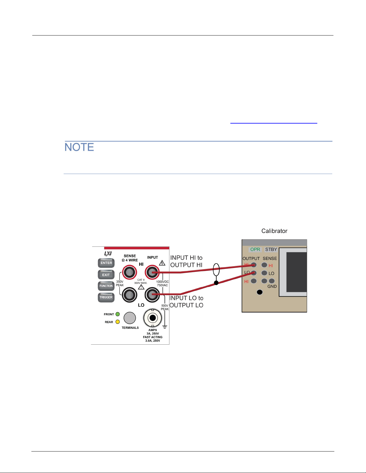
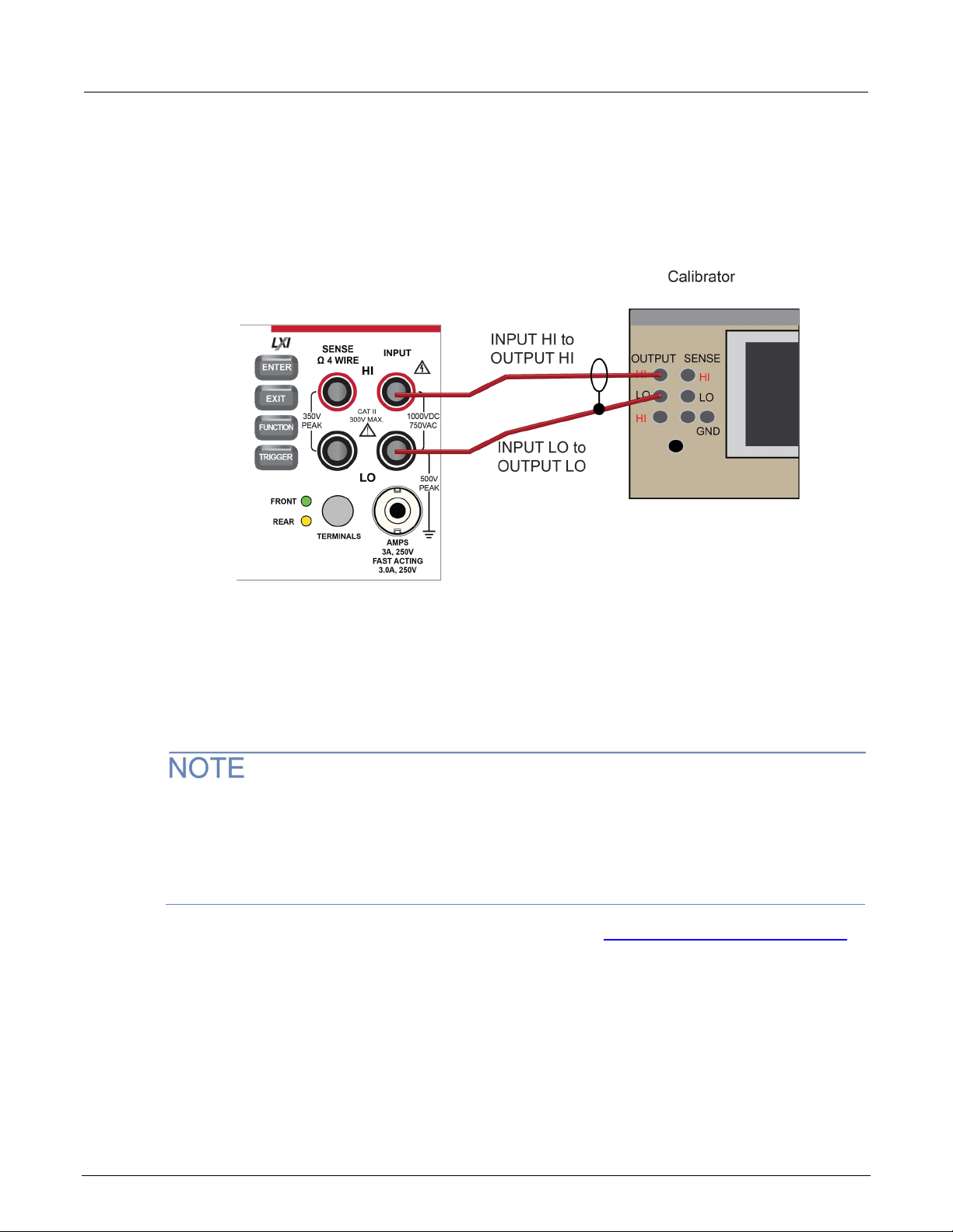
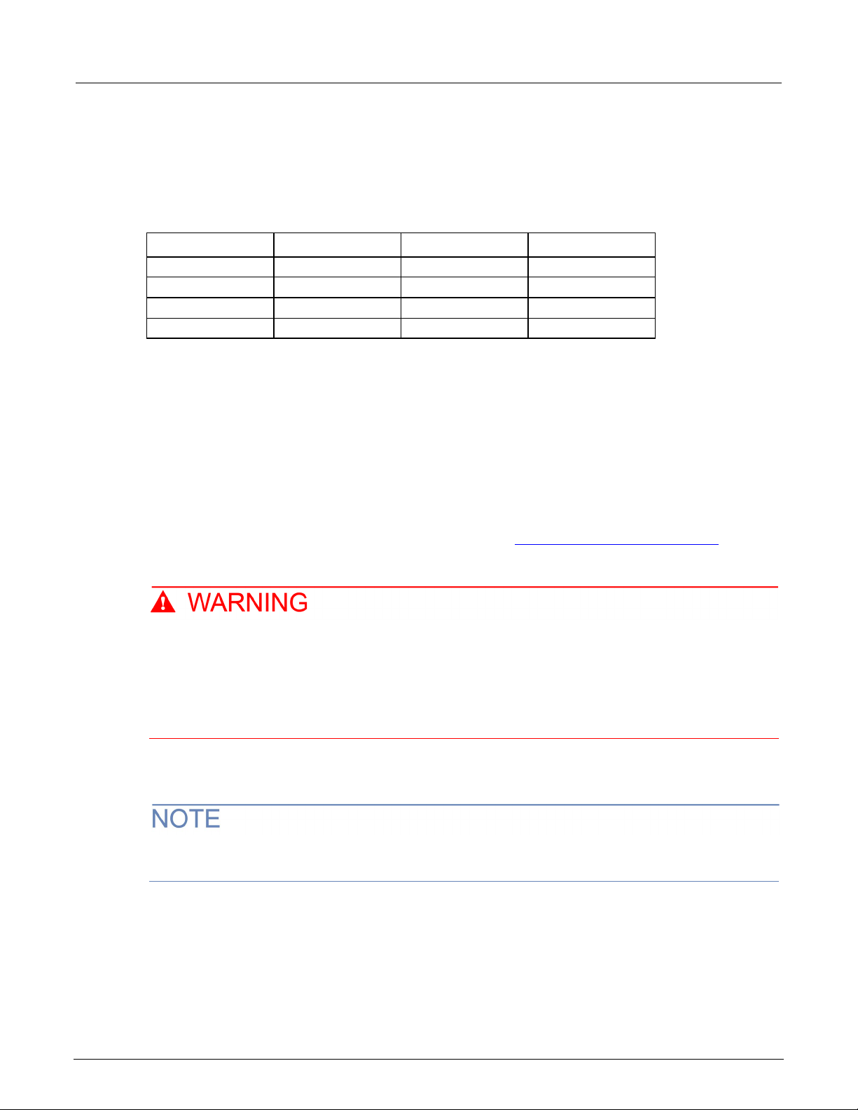
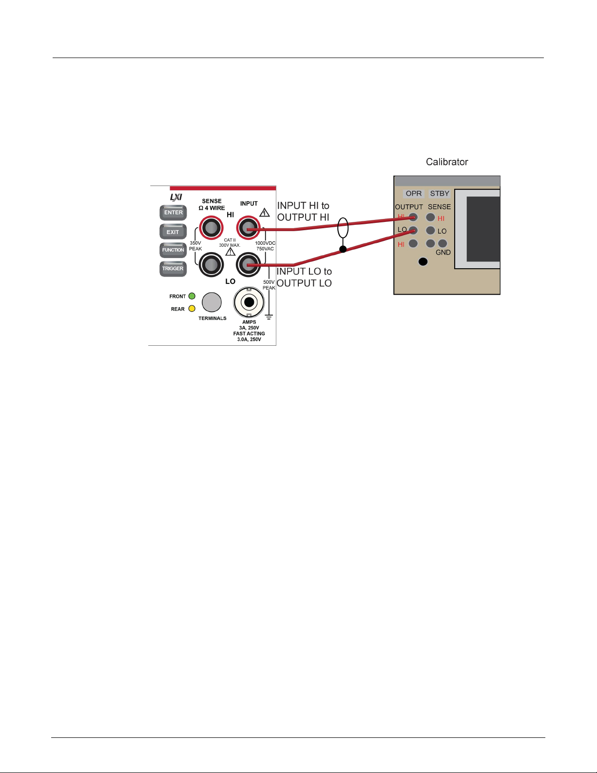
To verify dc voltage accuracy:
1. Use a low-thermal cable to connect the DMM6500 HI and LO INPUT terminals to the calibrator HI
and LO terminals as shown in the following figure.
(on
Figure 1: DC voltage 100 mV to 1000 V ranges verification connections
2. On the DMM6500, press the FUNCTION key and select DC voltage.
3. On the home screen, select the button next to Range and select 100 mV.
4. Press the MENU key.
5. Under Measure, select Settings.
6. Set Input Impedance to Auto.
7. Set the calibrator output to 0 V.
8. Set the calibrator to OPERATE.
DMM6500-905-01 Rev. E June 2022 2-7
Page 17
Section
Calibration and Adjustment Manual
Perform relative
offset
0
-0.01
0.01
Full scale (+)
100
99.9935
100.0065
Half scale (+)
50
49.995
50.005
Half scale (–)
-50
-50.005
-49.995
Full scale (–)
-100
-100.0065
-99.9935
Full scale (+)
1
0.999969
1.000031
Half scale (+)
0.5
0.499979
0.500021
Half scale (–)
-0.5
-0.500021
-0.499979
Full scale (–)
–1
–1.000031
-0.999969
Full scale (+)
10
9.9997
10.0003
Half scale (–)
–5
–5.00018
–4.99982
Full scale (–)
–10
–10.0003
–9.9997
2: Performance verification DMM6500 6½-Digit Multimeter with Scanning
9. Allow 5 minutes of settling time.
10. Press the MENU key.
11. Select Calculations.
12. [Only for the 100 mV range] Select Rel Acquire.
13. Source positive and negative full-scale and half-scale voltages and allow for proper settling.
14. Select each range on the DMM6500, allow for proper settling, and verify the ranges according to
the following tables.
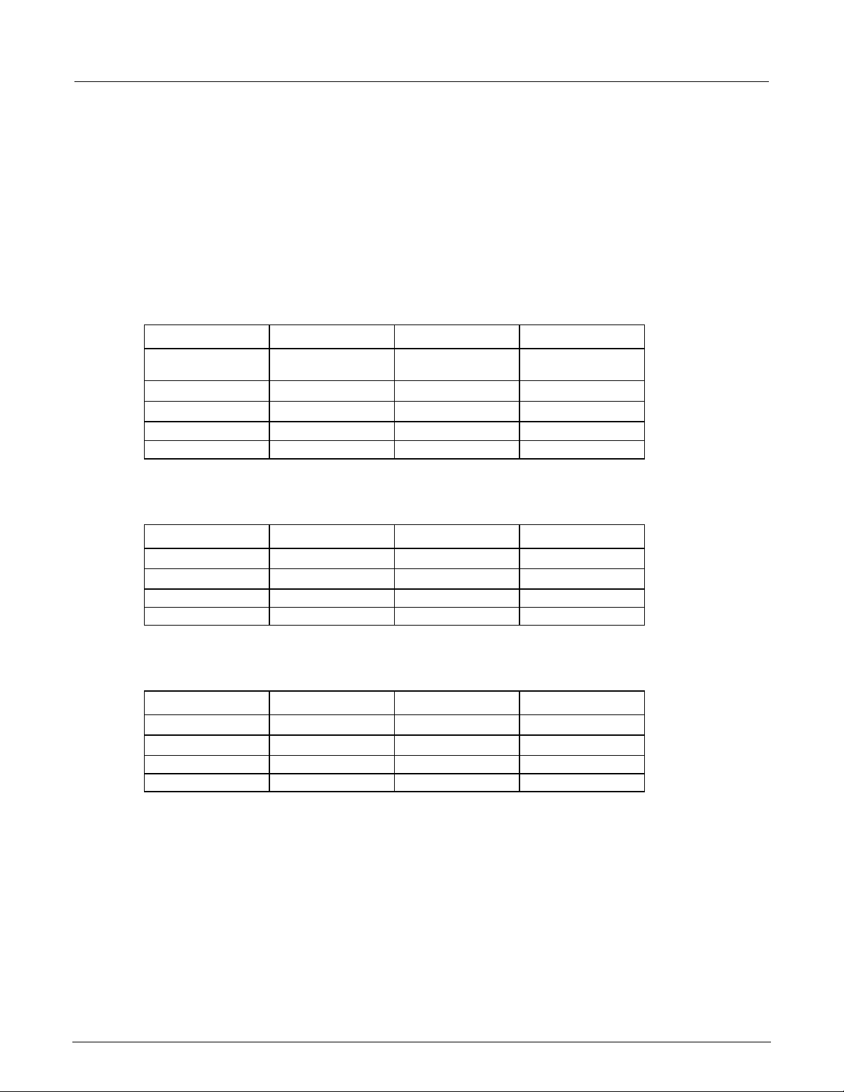
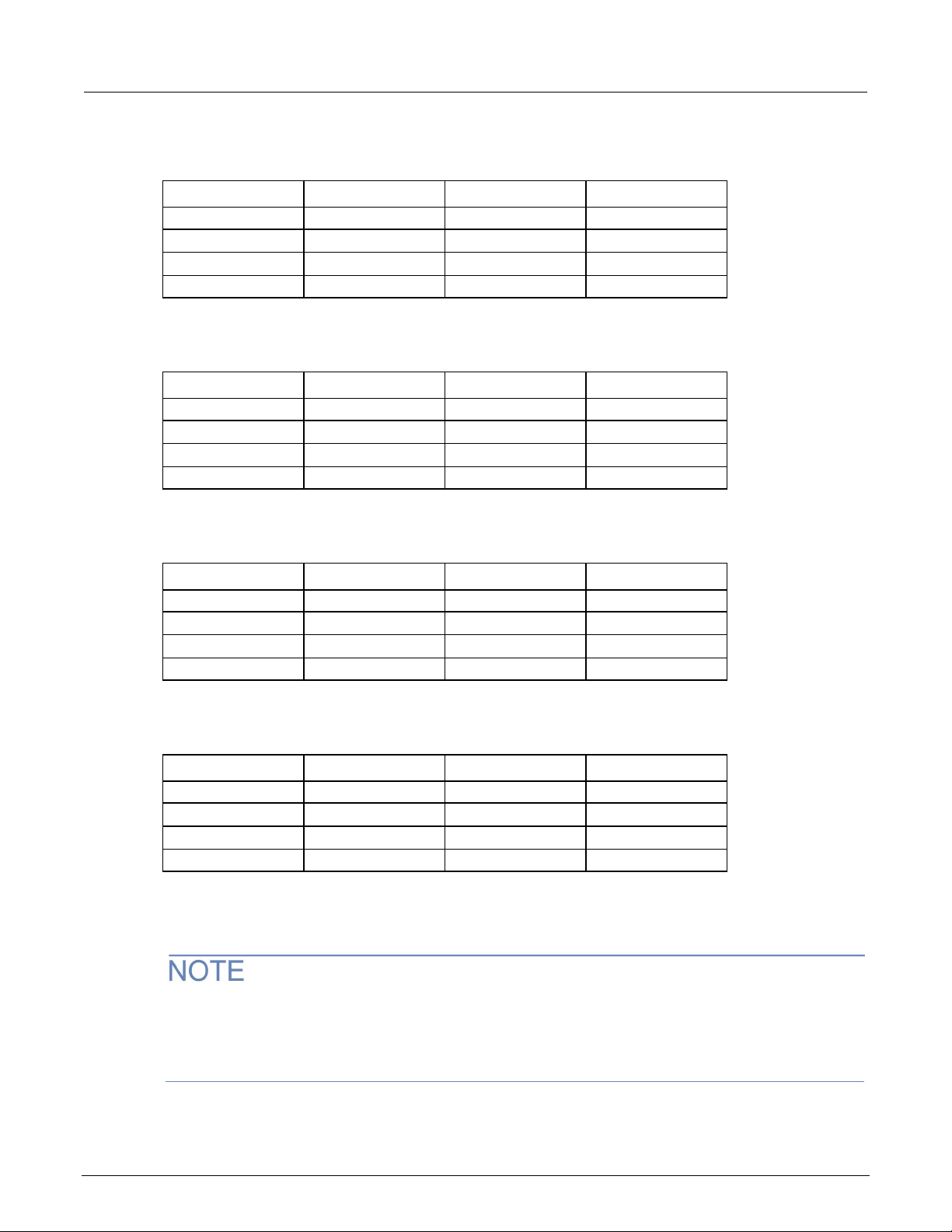
Verify the dc voltage 100 mV range
Description Nominal value Lower limit Upper limit
Verify the dc voltage 1 V range
Description Nominal value Lower limit Upper limit
Verify the dc voltage 10 V range
Description Nominal value Lower limit Upper limit
Half scale (+) 5 4.99982 5.00018
2-8 DMM6500-905-01 Rev. E June 2022
Page 18

DMM6500
Performance verification
Full scale (+)
100
99.954
100.0046
Half scale (–)
-50
-50.00315
-49.99685
Full scale (+)
1000
999.944
1000.056
Half scale (–)
-500
-500.026
-499.974
Full scale (–)
-1000
-1000.069
-999.931
6½-Digit Multimeter with Scanning Calibration and Adjustment Manual Section 2:
Verify the dc voltage 100 V range
The information in this section is intended for qualified service personnel only, as described
by the types of product users in the Safety precautions pages, provided at the beginning of
this document. Do not attempt these procedures unless you are qualified to do so.
Some of these procedures may expose you to hazardous voltages, that if contacted, could
cause personal injury or death. Use appropriate safety precautions when working with
hazardous voltages.
Description Nominal value Lower limit Upper limit
Half scale (+) 50 49.99685 50.00315
Full scale (–) -100 -100.0054 -99.9946
Verify the dc voltage 1000 V range
Description Nominal value Lower limit* Upper limit*
Half scale (+) 500 499.974 500.026
*For each additional volt over ±500 V, add 0.02 mV of uncertainty.
DMM6500-905-01 Rev. E June 2022 2-9
Page 19
Section
Calibration and Adjustment Manual
2: Performance verification DMM6500 6½-Digit Multimeter with Scanning
AC voltage verification
To verify ac voltage accuracy:
• For the 100 mV to 100 V ranges, apply accurate voltages from the calibrator to the DMM6500
front-panel terminals.
• For the 750 V range, connect the Fluke 5725A Amplifier to the calibrator. Apply accurate voltages
from the calibrator terminals to the terminals on the front panel of the DMM6500.
• Verify that the displayed readings are within specified limits.
Use the values in the tables following the steps below to verify the performance of the DMM6500.
Actual values depend on the published specifications (see Example reading limit calculation
2-4)).
The maximum input voltage between INPUT HI and INPUT LO is 750 V dc. Exceeding this
value may create a shock hazard.
(on page
The maximum common-mode voltage (the voltage between INPUT LO and chassis ground) is
500 V
. Exceeding this value may cause a breakdown in insulation that can create a shock
PEAK
hazard.
Verify ac voltage accuracy for the 100 mV to 100 V ranges
Use shielded, low-capacitance cabling. For the 100 mV to 100 V ranges, avoid loading that exceeds
1000 pF.
Excessive capacitance may result in additional load regulation uncertainties and could cause the
calibrator output to open (go into standby).
2-10 DMM6500-905-01 Rev. E June 2022
Page 20
DMM6500
Performance verification
6½-Digit Multimeter with Scanning Calibration and Adjustment Manual Section 2:
To verify ac voltage accuracy:
1. Connect the DMM6500 HI and LO INPUT connectors to the calibrator as shown in the following
figure.
Figure 2: Connections for ac voltage verification 100 mV to 100 V ranges
2. On the DMM6500, press the FUNCTION key and select AC voltage.
3. On the home screen, select the button next to Range and select 100 mV.
4. Press the MENU key.
5. Under Measure, select Settings.
6. Make sure that detector bandwidth is set to 30 Hz.
AC voltage is specified for the detector bandwidth setting of 3 Hz. Three Hz measures accurately for
input signals from 3 Hz to 300 kHz, with reading rates ≈ 2 readings/s. To improve verification
throughput to ≈ 20 readings/s, set detector bandwidth to 30 Hz for frequencies of 30 Hz to 300 kHz.
To verify frequencies 1 kHz and higher, set the detector bandwidth to 300 Hz for faster ≈ 200
readings/s throughput.
7. Source ac voltages for each of the frequencies listed in the Verify the ac voltage 100 mV range
(on page 2-12) table.
8. Repeat these steps for each range and frequency listed in the tables below. For each voltage
setting, be sure that the reading is within low and high limits.
DMM6500-905-01 Rev. E June 2022 2-11
Page 21
Section
Calibration and Adjustment Manual
0.1
20 Hz
99.91
100.09
0.1
1 kHz
99.91
100.09
0.1
50 kHz
99.83
100.17
0.1
100 kHz
99.32
100.68
1
20 Hz
.9991
1.0009
1
50 kHz
.9983
1.0017
1
100 kHz
.9932
1.0068
10
20 Hz
9.991
10.009
10
50 kHz
9.983
10.017
10
100 kHz
9.932
10.068
100
20 Hz
99.910
100.09
100
1 kHz
99.910
100.09
100
50 kHz
99.830
100.17
100
100 kHz
99.320
100.68
2: Performance verification DMM6500 6½-Digit Multimeter with Scanning
Verify the ac voltage 100 mV range
Nominal value Frequency Lower limit Upper limit
Verify the ac voltage 1 V range
Nominal value Frequency Lower limit Upper limit
1 1 kHz .9991 1.0009
Verify the ac voltage 10 V range
Nominal value Frequency Lower limit Upper limit
10 1 kHz 9.991 10.009
Verify the ac voltage 100 V range
Nominal value Frequency Lower limit Upper limit
Verify ac voltage accuracy for the 750 V range
Use shielded low capacitance cabling. For the 750 V range, avoid cable capacitances of >150 pF.
Excessive capacitance may result in additional load regulation uncertainties and could cause the
calibrator output to open (go into standby).
2-12 DMM6500-905-01 Rev. E June 2022
Page 22
DMM6500
Performance verification
6½-Digit Multimeter with Scanning Calibration and Adjustment Manual Section 2:
To verify ac voltage accuracy for the 750 V range:
1. Put the calibrator in Standby.
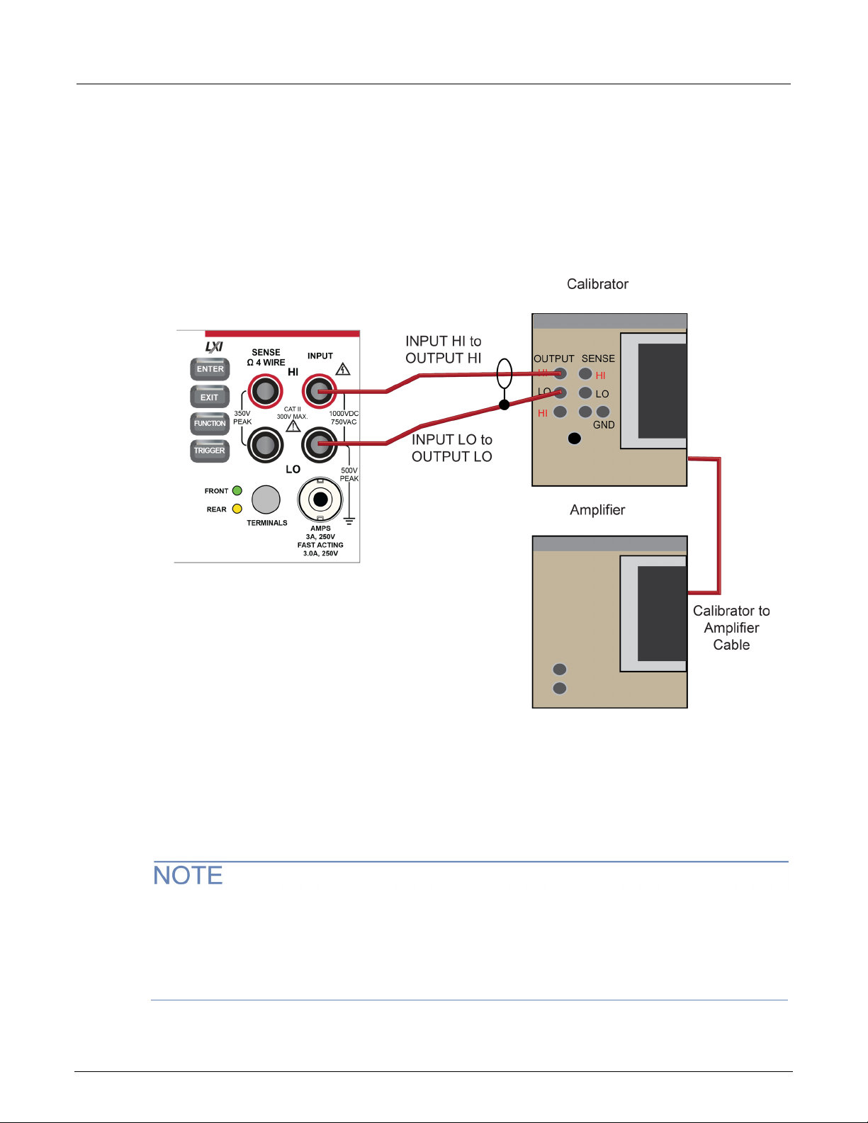
2. Connect the DMM6500 HI and LO INPUT connectors to the calibrator as shown in the following
figure.
3. For 750 V at 50 kHz and 100 kHz outputs, connect the calibrator to the Fluke 5725A amplifier.
Figure 3: Connections for ac voltage accuracy verification 750 V range
4. On the DMM6500, press the FUNCTION key and select AC voltage.
5. On the home screen, select the button next to Range and select 750 V.
6. Press the MENU key.
7. Under Measure, select Settings.
8. Ensure that detector bandwidth is set to 30 Hz.
AC voltage is specified for the detector bandwidth setting of 3 Hz. Three Hz measures accurately for
input signals from 3 Hz to 300 kHz, with reading rates ≈ 2 readings/s. To improve verification
throughput to ≈ 200 readings/s, set detector bandwidth to 30 Hz for frequencies of 30 Hz to 300 kHz.
To verify frequencies 1 kHz and higher, set the detector bandwidth to 300 Hz for faster ≈ 200
readings/s throughput.
DMM6500-905-01 Rev. E June 2022 2-13
Page 23
Section
justment Manual
740
50 Hz
739.33
740.67
740
1 kHz
739.33
740.67
740
100 kHz
734.96
745.04
2: Performance verification DMM6500 6½-Digit Multimeter with Scanning Calibration and Ad
9. Set the calibrator to OPERATE.
10. Source ac voltages for each of the frequencies listed in the "Verify the ac voltage 750 V range"
table, below. Be sure that the readings are within low and high limits.
Verify the ac voltage 750 V range
Nominal value Frequency Lower limit Upper limit
740 50 kHz 738.66 741.34
Digitize dc voltage verification
To verify digitize dc voltage accuracy, you will:
• Apply accurate voltages from the calibrator to the terminals on the front panel of the DMM6500.
• Verify that the displayed readings are within specified limits.
Use the values in the tables following the steps below to verify the performance of the DMM6500.
Actual values depend on the published specifications (see Example reading limit calculation
2-4)).
The maximum input voltage between INPUT HI and INPUT LO is 1000 V dc and 750 V ac.
Exceeding this value may create a shock hazard.
The maximum common-mode voltage (the voltage between INPUT LO and chassis ground) is
500 V
. Exceeding this value may cause a breakdown in insulation that can create a shock
PEAK
hazard.
Verify the digitize voltage 100 mV to 1000 V ranges
Use shielded low-thermal connections when testing the 100 mV and 1 V ranges to avoid errors
caused by noise or thermal effects. Connect the shield to the output LO terminal of the calibrator.
(on page
2-14 DMM6500-905-01 Rev. E June 2022
Page 24
DMM6500
Performance verification
6½-Digit Multimeter with Scanning Calibration and Adjustment Manual Section 2:
To verify digitize voltage accuracy:
1. Connect the DMM6500 HI and LO INPUT connectors to the calibrator as shown in the following
figure.
Figure 4: Connections for digitize voltage verification 100 mV to 1000 V ranges
2. On the DMM6500, press the FUNCTION key, select the Digitize Functions tab, and select
Digitize Voltage.
3. On the home screen, select the button next to Range and select 100 mV.
4. Press the MENU key.
5. Under Measure, select Settings.
6. Set the Sample Rate to 1000.
7. Set the Aperture to Auto.
8. Set the Count to 100.
9. Set the calibrator output to 0.00000 mV dc and allow the reading to settle.
10. Press the MENU key.
11. Under Measure, select Calculations.
12. Source positive and negative full-scale and half-scale voltages, as listed in the following table.
Verify the 100 mV to 100 V range settings listed in the tables below. For each voltage setting,
verify that the STATISTICS swipe screen reading for Average is within low and high limits.
The Fluke 5720A or 5730A calibrator 1000 V range 0.0 V setting is not verified.
DMM6500-905-01 Rev. E June 2022 2-15
Page 25
Section
Calibration and Adjustment Manual
Full scale (+)
100
99.94
100.06
Half scale (+)
50
49.95
50.05
Half scale (–)
-50
-50.05
-49.95
Full scale (–)
-100
-100.06
-99.94
Full scale (+)
1
0.9996
1.0004
Half scale (+)
0.5
0.49975
0.50025
Half scale (–)
-0.5
-0.50025
-0.49975
Full scale (–)
-1
-1.0004
-0.9996
Full scale (+)
10
9.996
10.004
Half scale (+)
5
4.9975
5.0025
Half scale (–)
-5
-5.0025
-4.9975
Full scale (–)
-10
-10.004
-9.996
Full scale (+)
100
99.96
100.04
Half scale (+)
50
49.975
50.025
Half scale (–)
-50
-50.025
-49.975
Full scale (–)
-100
-100.04
-99.96
Half scale (+)
500
499.75
500.25
Half scale (–)
–500
-500.25
-499.75
Full scale (–)
–1000
-1000.4
-999.6
2: Performance verification DMM6500 6½-Digit Multimeter with Scanning
Verify the digitize voltage 100 mV range
Description Nominal value Lower limit Upper limit
Verify the digitize voltage 1 V range
Description Nominal value Lower limit Upper limit
Verify the digitize voltage 10 V range
Description Nominal value Lower limit Upper limit
Verify the digitize voltage 100 V range
Description Nominal value Lower limit Upper limit
Verify the digitize voltage 1000 V range
Description Nominal value Lower limit Upper limit
Full scale (+) 1000 999.6 1000.4
2-16 DMM6500-905-01 Rev. E June 2022
Page 26
DMM6500
Performance verification
6½-Digit Multimeter with Scanning Calibration and Adjustment Manual Section 2:
Frequency verification
To verify frequency accuracy, you will:
• Apply accurate frequencies from the function generator to the terminals on the front panel of the
DMM6500.
• Verify that the displayed readings are within specified limits.
Use the values in the table following the steps below to verify the performance of the DMM6500.
Actual values depend on the published specifications (see Example reading limit calculation
2-4)).
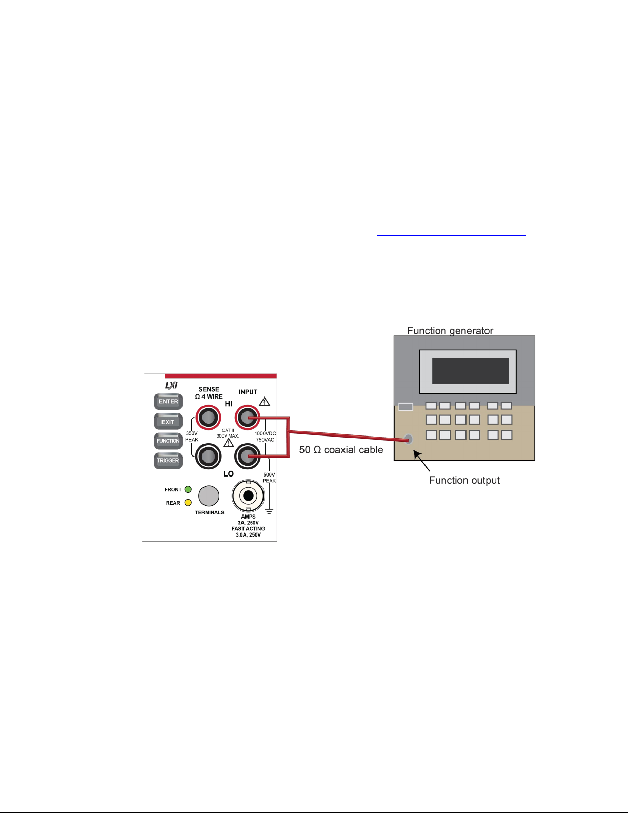
1. Connect the Keithley Instruments Model 3390 function generator to the DMM6500 INPUT HI and
LO terminals as shown in the following figure.
Figure 5: Connections for frequency verification and adjustment
(on page
2. On the DMM6500, press the FUNCTION key, select the Measure Functions tab, and select
Frequency.
3. Select the MENU key.
4. Under Measure, select Settings.
5. Set the Aperture to 250 ms.
6. Set the Threshold Range to 10 V.
7. Press the HOME key.
8. Source the voltage and frequency values as listed in Verify the frequency (on page 2-18
). For
each setting, be sure that the reading is within low and high limits.
DMM6500-905-01 Rev. E June 2022 2-17
Page 27
Section
libration and Adjustment Manual
10 Hz at 10 V
10
9.997
10.003
10 kHz at 5 V
10
9.9991
10.0009
100 kHz at 5 V
100
99.991
100.009
300 kHz at 5 V
300
299.973
300.027
2: Performance verification DMM6500 6½-Digit Multimeter with Scanning Ca
Verify the frequency
Use the following values to verify the performance of the DMM6500. Actual values depend on
published specifications (see Example reading limit calculation (on page 2-4
Description Frequency (Hz) Lower limit (Hz) Upper limit (Hz)
1 kHz at 5 V 1 0.9999 1.0001
Simulated thermocouple type J temperature verification
To verify thermocouple accuracy, you will:
• Apply accurate voltages from the calibrator to the terminals on the front panel of the DMM6500.
)).
• Verify that the displayed readings are within specified limits.
Thermocouple accuracy is verified by using a dc voltage calibrator to output values from standard
thermocouple tables available from the National Institute of Standards and Technology (NIST) or
other sources.
In the table following the steps below, three representative values are listed from a type J
thermocouple table for temperatures –190 °C, 0 °C, and 750 °C, with their respective thermocouple
voltages listed in the “Uncompensated calibrator source value” column. The calibrator source values
are based on NIST Monograph 175, reference data 60, version 2.0.
Verify thermocouple accuracy
Because the cable connecting the calibrator to the DMM6500 can have non-trivial thermal offset
voltages, you must first correct for these to verify the DMM6500 specifications.
2-18 DMM6500-905-01 Rev. E June 2022
Page 28
DMM6500
Performance verification
6½-Digit Multimeter with Scanning Calibration and Adjustment Manual Section 2:
To verify the simulated thermocouple type J temperature:
1. Connect the DMM6500 HI and LO INPUT terminals to the calibrator HI and LO terminals as
shown in the following figure.
Figure 6: Connections for thermocouple verification
2. On the DMM6500, press the FUNCTION key and select DC voltage.
3. Press the MENU key.
4. Under Measure, select Settings.
5. Set the range to 100 mV.
6. Set Input Impedance to Auto.
7. Set autozero to On.
8. Select Integration Rate. The Integration Rate dialog box opens.
9. Set the unit to NPLC.
10. Set NPLC to 1 PLC.
11. Select OK and press the HOME key to return to the Home Screen.
12. Set the calibrator to output 0 V and enable the output.
13. Allow five minutes for settling of the thermal voltage.
14. Record the measured offset voltage to 1 µV precision. If necessary, use the DMM6500 filter
settings to reduce the noise of this measurement (for filter settings, go to MENU > Measure
Calculations).
15. Press the DMM6500 FUNCTION key and select Temperature.
16. Press the MENU key.
17. Under Measure, select Settings.
DMM6500-905-01 Rev. E June 2022 2-19
Page 29

Section
Calibration and Adjustment Manual
–190 °C
–7.659 mV
–190.2 °C
–189.8 °C
0 °C
0.000 mV
–0.2 °C
0.2 °C
750 °C
42.281 mV
749.8 °C
750.2 °C
2: Performance verification DMM6500 6½-Digit Multimeter with Scanning
18. On the Measure Settings screen, set the following values:
Units: °C
Transducer: TC
Thermocouple: J
Temperature (simulated reference temperature): 0 °C
Integration Rate: 1 PLC
Auto Zero: On
19. Set the calibrator to the simulated thermocouple voltage you want (from the following table), first
correcting for the offset voltage measured in step 14. For example, if the measured offset voltage
was –2 µV, set the calibrator to –7.659 mV – (–0.002 mV), which equals –7.657 mV, to simulate
–190 °C.
20. Verify that the DMM6500 reading is within lower and upper limits.
21. Repeat steps 18 and 19 for each value in the following table.
se the following values to verify the performance of the DMM6500. Actual values depend on
U
published specifications (see Example reading limit calculation (on page 2-4
)).
Simulated
temperature
Uncompensated
calibrator source
value (V)
Lower limit Upper limit
Simulated RTD temperature verification
Use the following information to verify the performance of the DMM6500. Actual calibrator source
values will vary. RTD verification is based on the calibrator sourcing resistance and the DMM6500
conversion of the resistance measurement to calculated temperature based on the Callendar-Van
Dusen equation.
To verify RTD temperature accuracy, you will:
• Apply accurate resistance from the calibrator to the terminals on the front panel of the DMM6500.
• Verify that the displayed readings are within specified limits.
2-20 DMM6500-905-01 Rev. E June 2022
Page 30

DMM6500
Performance verification
6½-Digit Multimeter with Scanning Calibration and Adjustment Manual Section 2:
RTD equations
The temperature versus resistance readings listed in the RTD reference tables are calculated using
the Callendar-Van Dusen equation. There are two equations that are based on different temperature
ranges. There is an equation for the –200 °C to 0 °C range and one for the 0 °C to 850 °C range.
Equation for –200 °C to 0 °C temperature range
R
= R0 [1 + AT + BT2 + CT3(T – 100)]
RTD
where:
• R
• R
is the calculated resistance of the RTD
RTD
is the known RTD resistance at 0 °C
0
• T is the temperature in °C
• A = alpha [1 + (delta/100)]
• B = –1 (alpha)(delta)(1E-4)
• C = –1 (alpha)(beta)(1E-8)
The alpha, beta, and delta values are listed in the following table.
Equation for 0 °C to 850 °C temperature range
R
= R0 (1 + AT + BT2)
RTD
where:
• R
• R
is the calculated resistance of the RTD
RTD
is the known RTD resistance at 0 °C
0
• T is the temperature in °C
• A = alpha [1 + (delta/100)]
• B = –1 (alpha)(delta)(1E-4)
The alpha and delta values are listed in the following table.
DMM6500-905-01 Rev. E June 2022 2-21
Page 31

Section
Calibration and Adjustment Manual
PT100
ITS-90
0.00385055
0.10863
1.49990
100.0000
D100
0.003920
0.10630
1.49710
F100
0.003900
0.11000
1.49589
PT385
IPTS-68
0.003850
0.11100
1.50700
PT3916
0.003916
0.11600
1.50594
2: Performance verification DMM6500 6½-Digit Multimeter with Scanning
RTD parameters for equations
The RTD parameters for the Callendar-Van Dusen equations are listed in the following table.
DMM6500 resistance to temperature device (RTD)
Type Standard Alpha Beta Delta R0 at 0 °C (Ω)
Verify the simulated RTD temperature
Use the values in the tables following the steps below to verify the performance of the DMM6500.
Actual values depend on the published specifications (see Example reading limit calculation
2-4)).
(on page
To verify RTD accuracy:
1. For 4-wire accuracy, connect the DMM6500 INPUT and SENSE terminals to the calibrator as
shown in the following figure.
Figure 7: Connections for 4-wire RTD accuracy verification
2-22 DMM6500-905-01 Rev. E June 2022
Page 32

DMM6500
Performance verification
6½-Digit Multimeter with Scanning Calibration and Adjustment Manual Section 2:
2. For 3-wire accuracy, connect the DMM6500 INPUT and SENSE terminals to the calibrator as
shown in the following figure.
The SENSE HI wire is not required for 3-wire RTD measurements. For 3-wire RTD, accuracy is for
< 0.1 Ω lead resistance mismatch for input HI and LO. Add 0.25 °C per 0.1 Ω of HI-LO lead
resistance mismatch.
Figure 8: Connections for 3-wire RTD accuracy verification
3. On the DMM6500, press the FUNCTION key and select Temperature.
4. Press the MENU key.
5. Under Measure, select Settings.
6. Select Transducer.
7. Set the Type to 4-wire RTD or 3-Wire RTD.
8. Set the RTD Type to PT100.
9. Press the HOME key.
10. On the calibrator, select 19 Ω source resistance.
11. Select the OPER and EX SNS keys.
12. Record DMM6500 accuracies.
13. Refer to the table for PT100 accuracies.
Fluke 5720 and 5730 resistance source values vary and may require new resistance-to-temperature
target accuracy values.
DMM6500-905-01 Rev. E June 2022 2-23
Page 33

Section
Calibration and Adjustment Manual
1.000000E+02
3.850550E-03
1.086300E-01
3.908304E-03
-5.775440E-07
-4.182852E-12
19
18.999520
-198.8900
0.0259
0.3241
100
99.99707
-0.0075
0.0235
0.2932
190
189.99234
238.6775
0.0218
0.2725
2: Performance verification DMM6500 6½-Digit Multimeter with Scanning
14. Repeat for 100 Ω and 190 Ω source values.
Example PT100
R0
alpha
beta
delta
A
B
C
1.499900E+00
Nominal
calibrator
value
(Ω)
Actual calibrator
value
(Ω)
Resistance verification
Use the following information to verify the performance of the DMM6500 resistance functions.
Four-wire resistance verification
To verify the 4-wire resistance function, you will:
• Use shielded, Teflon-insulated or equivalent cables in a 4-wire configuration.
• Characterize the calibrator 1 Ω and 10 Ω nominal values with an external reference digital
multimeter (DMM); verify accuracy from the reference DMM readings.
Temperature
(°C)
4-wire RTD 3-wire RTD
±0.06 °C accuracy
(±Ω from actual
calibrator value)
±0.75 °C accuracy
(±Ω from actual
calibrator value)
• For the 100 Ω to 100 MΩ ranges, verify accuracy from actual calibrator source values.
2-24 DMM6500-905-01 Rev. E June 2022
• Verify that the displayed readings are within specified limits.
Page 34

DMM6500
Performance verification
6½-Digit Multimeter with Scanning Calibration and Adjustment Manual Section 2:
To verify 4-wire resistance accuracy:
1. Connect the DMM6500 INPUT and SENSE terminals to the calibrator as shown in the following
figure.
Figure 9: Connections for 4-wire resistance accuracy verification
2. Set the calibrator for 4-wire resistance with external sense on.
3. On the DMM6500, press the FUNCTION key and select 4W Res.
4. Press the MENU key.
5. Under Measure, select Settings.
6. Set Offset Compensation On.
7. Verify that Open Lead Detector is Off.
8. On the home screen, select the button next to Range and select 1 Ω.
9. Source the nominal zero and full-scale resistance values for the 1 Ω to 10 kΩ ranges. Source the
nominal zero value for the 100 kΩ range. Refer to the tables in Calculated limits (on page 2-26
).
10. For the 100 kΩ range, only verify 0 Ω with Offset Compensation set to On.
11. Set Offset Compensation to Off.
12. Verify full-scale 100 kΩ on the 100 kΩ range and 0 and full-scale for the 1 MΩ and 10 MΩ ranges.
13. Verify that the readings are within calculated limits.
When Offset Compensation is set to On, ranges are limited to 1 Ω to 10 kΩ. When Offset
Compensation is set to Off, all ranges (1 Ω to 100 MΩ) are available from all interfaces.
DMM6500-905-01 Rev. E June 2022 2-25
Page 35

Section
Calibration and Adjustment Manual
1
0 0 -0.1
0.1 1 0.999973
0.999688
1.000258
10
0 0 -0.1
0.1
100
0 0 -0.1
0.1
100
99.9975
99.987
100.008
1 K
0 0 -1 1 1
0.99999
0.99991
1.00007
10 K
0 0 -1 1 10
9.99982
9.99901
10.00063
100 K
0 0 -10
10
2: Performance verification DMM6500 6½-Digit Multimeter with Scanning
You can use either the front-panel controls or remote interface commands to set measurement
parameters for verification. For calibration, you must use remote interface commands. The example
below is an example of remote interface commands that will generate event messages.
To do the same steps over the remote interface, send the commands:
dmm.measure.func = dmm.FUNC_4W_RESISTANCE
dmm.measure.offsetcompensation.enable = dmm.OCOMP_ON
dmm.measure.range = 1e6
The following warning message is displayed:
1131, Parameter, measure range, expected value from 1 to 100000
Set dmm.measure.offsetcompensation.enable = dmm.OCOMP_OFF, and then set
dmm.measure.range = 1e6 to run without warnings.
Verify that the readings are within calculated limits.
The values and limits in the following tables are for example only. You must calculate test limits
based on the actual resistance values output by your calibrator or resistance source (see
Example
reading limit calculation (on page 2-4)).
Range
(Ω)
Nominal calibrator
values
(Ω)
Typical reference
DMM reading
(Ω)
Lower limit
(Ω)
Upper limit
(Ω)
10 9.99983 9.99878 10.00088
Range
(Ω)
Nominal calibrator
values
(Ω)
Actual calibrator
value
(Ω)
Lower limit
(Ω)
Upper limit
(Ω)
2-26 DMM6500-905-01 Rev. E June 2022
Page 36

DMM6500
ion
1 M
0 0 -1 1 1
0.999966
0.99986
1.000072
10 M
0 0 -1 1 10
9.99931
9.99521
10.00341
6½-Digit Multimeter with Scanning Calibration and Adjustment Manual Section 2: Performance verificat
Four-wire resistance verification with offset compensation off
The values and limits in the following tables are for example only. You must calculate test limits based
on the actual resistance values output by your calibrator or resistance source (see
Example reading
limit calculation (on page 2-4)).
For 10 MΩ verification, the Sense HI cable is optional. Measurement is with Input HI and LO and
Sense LO only.
Range
(Ω)
100 K 100 100.0012 99.9928 100.0098
Nominal calibrator
values
(Ω)
Verify 2-wire resistance accuracy
To verify the 2-wire resistance function 100 MΩ range, you will:
• Use shielded, Teflon-insulated or equivalent cables in a 2-wire configuration.
• Apply accurate resistance from the calibrator to the terminals on the front panel of the DMM6500.
• Verify that the displayed readings are within specified limits.
Verify resistance 100 MΩ range
To verify the 100 MΩ range:
Actual calibrator
value
(Ω)
Lower limit
(Ω)
Upper limit
(Ω)
1. Connect the DMM6500 INPUT to the calibrator as shown in the following figure.
DMM6500-905-01 Rev. E June 2022 2-27
Page 37

Section
Calibration and Adjustment Manual
100 M
0 0 -10
10
100
100.001
99.798
100.204
2: Performance verification DMM6500 6½-Digit Multimeter with Scanning
Figure 10: Connections for 100 MΩ verification
2. Set the calibrator for 2-wire resistance with external sense off.
3. On the DMM6500, press the FUNCTION key and select 2W Res.
4. On the home screen, select the button next to Range and select 100 MΩ.
5. Source the nominal full-scale resistance values for the 100 MΩ range as shown in the following
table.
The values and limits in the following tables are for example only. You must calculate test limits
based on the actual resistance values output by your calibrator or resistance source (see
Example
reading limit calculation (on page 2-4)).
Range (Ω) Nominal calibrator
values (Ω)
Actual calibrator
(Ω)
Lower limit (Ω) Upper limit (Ω)
2-28 DMM6500-905-01 Rev. E June 2022
Page 38

DMM6500
Performance verification
6½-Digit Multimeter with Scanning Calibration and Adjustment Manual Section 2:
DC current verification
The DMM6500 dc current ranges can be verified using several methods, depending on the level of
measurement uncertainty required. This manual describes the verification procedure using a Fluke
8508A or 8588A reference digital multimeter (DMM) in series with the DMM6500 to determine the
nominal test current value for the 10 µA to 100 mA ranges. For the 1 A to 10 A ranges, this manual
describes using direct output from a Fluke Model 5720A or 5725A calibrator.
These configurations are adequate for most purposes, but may not provide sufficient test uncertainty
ratio (TUR) for some users. You must evaluate the measurement uncertainties and ensure that they
are adequate for your use.
DC current 10 µA to 100 mA range verification
When verifying dc current on the 10 µA to 100 mA ranges, systematic calibrator and cable offsets
must be compensated and test limits calculated based on reference digital multimeter (DMM)
readings.
In the following section, offset measurements may exceed DMM6500 zero-current measurement
specifications due to systematic source offset current from the test setup.
To verify the DMM6500 specifications with zero input current, disconnect all cables and calibrators
from the DMM6500 input. This is a separate setup from that used in the procedure below for
mid-scale and full-scale readings.
DMM6500-905-01 Rev. E June 2022 2-29
Page 39

Section
Calibration and Adjustment Manual
2: Performance verification DMM6500 6½-Digit Multimeter with Scanning
To prepare the DMM6500 for dc current accuracy verification:
1. Set up the DMM6500 for dc current and the range being tested. Make sure relative offset is
disabled.
2. Connect the calibrator, DMM6500, and reference DMM as shown in the following figure.
Figure 11: Connection for dc current
To verify DMM6500 accuracy for each range:
1. Set the calibrator to source zero current.
2. Set the reference DMM to DC Current and select the appropriate range to be verified. Use the
Model 8508A or 8588A 200 µA range to verify the DMM6500 10 µA and 100 µA ranges. Use the
Model 8508A or 8588A 2 mA, 20 mA, and 200 mA ranges to verify the DMM6500 1 mA, 10 mA,
and 100 mA ranges, respectively.
3. On the calibrator, select the OPR/STBY key. Make sure that the front panel displays OPERATE.
4. On the DMM6500, press the MENU key.
5. Select Calculations. The Calculation Settings screen is displayed.
6. On the reference DMM, zero the range for system offset.
7. Set the calibrator to source the current for the range you are verifying (listed in the 1 mA
verification table in Test limit calculation for 10 µA to 100 mA ranges).
2-30 DMM6500-905-01 Rev. E June 2022
Page 40

DMM6500
rmance verification
10 µA
10
0.00500
100 µA
100
0.0500
5
0.00275
50
0.0275
–5
0.00275
–50
0.0275
1 mA
1
0.000500
10 mA
10
0.00250
0.5
0.000275
5 0.00150
–0.5
0.000275
–5
0.00150
–1
0.000500
–10
0.00250
6½-Digit Multimeter with Scanning Calibration and Adjustment Manual Section 2: Perfo
8. Note the offset-compensated reference DMM reading, and calculate limits based on DMM6500
specifications (use the reference DMM reading as the expected value and verify the DMM6500
accuracy from the calculated reference DMM current).
Test limit calculation for 10 µA to 100 mA ranges
The following tables list nominal test current for 10 µA to 100 mA ranges. Test limits must be
calculated relative to actual current, as determined by the reference digital multimeter (DMM)
measurement. For example, using a specification of 60 ppm of reading + 9 ppm of range on the
10 mA range, the reference DMM measures 5.00012 mA on the nominal 5 mA test.
Specification tolerance = 5.00012 (mA) × 60 ppm + 10 (mA) × 9 ppm = 0.000390072 mA
Lower test limit = 5.00012 – 0.000390072 = 4.999729928 mA
Upper test limit = 5.00012 + 0.000390072 = 5.000510072 mA
Although the specification tolerance calculated above from the actual test current differs slightly from
the values listed in the table (based on nominal value), this difference is generally much smaller than
the measurement uncertainty and can be ignored. As a result, the test limits can be calculated from
the table specification tolerance as:
Lower test limit = 5.00012 – 0.00039 = 4.99973 mA
Upper test limit = 5.00012 + 0.00039 = 5.00051 mA
9. Repeat steps 1 through 8 for all ranges (10 µA through 100 mA).
Range Nominal
input (µA)
–10 0.00500 –100 0.0500
Specification
tolerance (µA) (based
on nominal)
Range Nominal
input (µA)
Specification
tolerance (µA)
(based on nominal)
Range Nominal
input (µA)
Specification
tolerance (µA) (based
on nominal)
Range Nominal
input (µA)
Specification
tolerance (µA)
(based on nominal)
DMM6500-905-01 Rev. E June 2022 2-31
Page 41

Section
Calibration and Adjustment Manual
2: Performance verification DMM6500 6½-Digit Multimeter with Scanning
DC current 100 mA to 3 A range verification
To verify dc current accuracy on the 100 mA to 3 A ranges, you will:
• Apply accurate current from the dc current calibrator directly to the DMM6500 front-panel
terminals.
• Verify that the displayed readings are within specified limits.
To verify dc current accuracy:
1. Set up the DMM6500 for dc current and the range being tested. Make sure that relative offset is
disabled.
2. Connect the DMM6500 and calibrator as shown in the following figure.
Figure 12: Connections for 100 mA to 3 A range verification
Zero verify the DMM6500:
1. On the calibrator, select the OPR/STBY key. Make sure that the front panel displays STANDBY.
2. Set the ranges to 100 mA.
3. Verify the DMM6500 zero reading for each range.
4. Source dc current from the following table. For each setting, be sure that the reading is within
stated limits.
5. Repeat these steps for the 1 A and 3 A ranges.
2-32 DMM6500-905-01 Rev. E June 2022
Page 42

DMM6500
Performance verification
Full scale (+)
100
99.975
100.025
Half scale (+)
50
49.985
50.015
Half scale (–)
-50
-50.015
-49.985
Full scale (–)
-100
-100.025
-99.975
Full scale (+)
1
0.99955
1.00045
Half scale (+)
0.5
0.49975
0.50025
Half scale (–)
–0.5
-0.50025
-0.49975
Full scale (–)
–1
-1.00045
-0.99955
Half scale (+)
1.5
1.49913
1.50087
Half scale (–)
–1.5
–1.50087
–1.49913
*Full scale (–)
–2
–2.00112
–1.99888
* The 3 A range full-scale test points are limited to 2 A in this table because of the accuracy
limitations of Fluke Models 57xxA and 5725A series calibrators at currents above 2.2 A.
6½-Digit Multimeter with Scanning Calibration and Adjustment Manual Section 2:
Verify dc current 100 mA range
Description Calibrator
Verify dc current 1 A range
Description Calibrator
Verify dc current 3 A range
Description Calibrator
*Full scale (+) 2 1.99888 2.00112
Lower limit Upper limit
setpoint (A)
Lower limit Upper limit
setpoint (A)
Lower limit Upper limit
setpoint (A)
Verify dc current 10 A range
See DC current 10 A range verification (on page 2-43) under Rear-panel verification (on page 2-43).
Digitize current verification
The following topics describe how to verify digitized dc current on the DMM6500.
DMM6500-905-01 Rev. E June 2022 2-33
Page 43

Section
Calibration and Adjustment Manual
Full scale (+)
99.998
99.878
100.118
Half scale (+)
49.9991
49.9141
50.0841
Half scale (–)
-49.993
-50.0843
-49.9143
Full scale (–)
-99.9985
-100.1185
-99.8785
2: Performance verification DMM6500 6½-Digit Multimeter with Scanning
Verify digitize current 100 µA to 3 A ranges
To verify digitize dc current accuracy:
1. Connect the DMM6500 and calibrator as shown in the following figure.
Figure 13: Connections for digitize dc current 10 µA to 3 A range verification
2. Press the FUNCTION key.
3. Select the Digitize Functions tab and select Digitize Current.
4. Press the HOME key.
5. Set the Range to 10 µA.
6. Press the MENU key.
7. Under Measure, select Settings.
8. Set the Sample Rate to 1000.
9. Set the Aperture to Auto or 1 ms.
10. Set the Count to 100.
11. Source positive and negative full-scale and half-scale currents, as listed in the following tables.
12. Repeat these steps for the 1 mA to 3 A range settings listed in the following tables.
Verify digitize current 100 µA range
Description Calibrator setpoint
(A)
Lower limit Upper limit
2-34 DMM6500-905-01 Rev. E June 2022
Page 44

DMM6500
Performance verification
Full scale (+)
0.999993
0.998993
1.000993
Half scale (+)
0.499998
0.499348
0.500648
Half scale (–)
-0.500009
-0.500659
-0.499359
Full scale (–)
-1.000017
-1.001017
-0.999017
Full scale (+)
10.00004
9.99204
10.00804
Half scale (+)
5.00004
4.99454
5.00554
Half scale (–)
-5.00003
-5.00553
-4.99453
Full scale (–)
-10.00006
-10.00806
-9.99206
Full scale (+)
100
99.92
100.08
Half scale (+)
50
49.945
50.055
Half scale (–)
-50
-50.055
-49.945
Full scale (–)
-100
-100.08
-99.92
Full scale (+)
1
0.999
1.001
Half scale (+)
0.5
0.49935
0.50065
Half scale (–)
–0.5
-0.50065
-0.49935
Full scale (–)
–1
-1.001
-0.999
6½-Digit Multimeter with Scanning Calibration and Adjustment Manual Section 2:
Verify digitize current 1 mA range
Description Calibrator setpoint
(A)
Verify digitize current 10 mA range
Description Calibrator setpoint
(A)
Verify digitize current 100 mA range
Description Calibrator setpoint
(A)
Lower limit Upper limit
Lower limit Upper limit
Lower limit Upper limit
Verify digitize current 1 A range
Description Calibrator setpoint
(A)
Lower limit Upper limit
DMM6500-905-01 Rev. E June 2022 2-35
Page 45

Section
Calibration and Adjustment Manual
*Full scale (+)
2
1.997
2.003
Half scale (+)
1.5
1.49745
1.50255
Half scale (–)
–1.5
–1.50255
–1.49745
*Full scale (–)
–2
–2.003
–1.997
* The 3 A range full-scale test points are limited to 2 A in this table because of the accuracy
limitations of Fluke Models 57xxA and 5725A series calibrators at currents above 2.2 A.
2: Performance verification DMM6500 6½-Digit Multimeter with Scanning
Verify digitize current 3 A range
Description Calibrator setpoint
(A)
Lower limit Upper limit
Verify digitize current 10 A range
See Digitize current 10 A range verification (on page 2-45) under Rear-panel verification (on page 2-
43).
AC current verification
The following topics describe how to verify ac current.
Verify ac current on the 100 µA to 3 A ranges
To verify ac current accuracy, you will:
• Apply accurate voltages from the Fluke 5720A or 5730A multifunction calibrator to the DMM6500
front-panel terminals.
• Verify that the displayed readings fall within specified limits.
Use the values in the following tables to verify the performance of the DMM6500. Actual values
depend on the published specifications (see Example reading limit calculation (on page 2-4
To verify ac current accuracy:
1. On the DMM6500, press the FUNCTION key and select AC Current.
2. Press the HOME key.
3. Set the range you are verifying.
4. Press the MENU key.
5. Under Measure, select Settings.
6. Make sure that Detector Bandwidth is set to 30 Hz.
)).
2-36 DMM6500-905-01 Rev. E June 2022
Page 46

DMM6500
Performance verification
100 µA at 20 Hz
100
99.83
100.17
100 µA at 1 kHz
100
99.83
100.17
1 mA at 20 Hz
1
0.9986
1.0014
1 mA at 1 kHz
1
0.9986
1.0014
1 mA at 4.9 kHz
1
0.9986
1.0014
6½-Digit Multimeter with Scanning Calibration and Adjustment Manual Section 2:
AC current is specified for the detector bandwidth setting of 3 Hz. 3 Hz measures accurately for input
signals from 3 Hz to 10 kHz, with reading rates of ≈ 0.5 readings/s. To improve verification
throughput to ≈ 3.3 readings/s, set detector bandwidth to 30 Hz for frequencies of 30 Hz to 10 kHz.
To verify frequencies 1 kHz and higher, set the detector bandwidth to 300 Hz for faster ≈ 55
readings/s throughput.
7. Connect the DMM6500 to the calibrator as shown in the following figure.
Figure 14: Connections for ac current verification
8. Source ac current for each of the frequencies listed in the following tables.
9. For each setting, make sure that the reading is within low and high limits.
Verify ac current 100 µA range
Description Verification point Lower limit Upper limit
Verify ac current 1 mA range
Description Verification point Lower limit Upper limit
DMM6500-905-01 Rev. E June 2022 2-37
Page 47

Section
Calibration and Adjustment Manual
10 mA at 40 Hz
10
9.986
10.14
10 mA at 1 kHz
10
9.986
10.14
10 mA at 4.9 kHz
10
9.986
10.14
100 mA at 40 Hz
100
99.86
100.14
100 mA at 1 kHz
100
99.86
100.14
100 mA at 4.9 kHz
100
99.86
100.14
1 A at 40 Hz
1.000
0.9986
1.0014
1 A at 4.9 kHz
1.000
0.9986
1.0014
2 A at 40 Hz
2.000
1.9952
2.0048
2 A at 1 kHz
2.000
1.9952
2.0048
2 A at 4.9 kHz
2.000
1.9952
2.0048
2: Performance verification DMM6500 6½-Digit Multimeter with Scanning
Verify ac current 10 mA range
Description Verification point Lower limit Upper limit
Verify ac current 100 mA range
Description Verification point Lower limit Upper limit
Verify ac current 1 A range
Description Verification point Lower limit Upper limit
1 A at 1 kHz 1.000 0.9986 1.0014
Verify ac current 3 A range
Description Verification point Lower limit Upper limit
Verify ac current 10 A range
See AC current 10 A verification (on page 2-47) under Rear-panel verification (on page 2-43).
2-38 DMM6500-905-01 Rev. E June 2022
Page 48

DMM6500
Performance verification
6½-Digit Multimeter with Scanning Calibration and Adjustment Manual Section 2:
Capacitance verification
To compensate for capacitance offset of the cable and 1 µF thru 100 µF decade box:
1. Connect the DMM6500, shielded banana cable, banana to dual BNC cable, and 1 µF through
100 µF decade capacitor box as shown in the following diagram.
Figure 15: Connect DMM6500 to decade capacitor box
2. Set the decade capacitor box to 0 F.
3. On the DMM6500, press the FUNCTION key, select the Measure Functions tab, and select
Capacitance.
4. Press the MENU key.
5. Under Measure, select Settings.
6. Set the Range to 1 nF.
7. Press the MENU key.
DMM6500-905-01 Rev. E June 2022 2-39
Page 49

Section
Calibration and Adjustment Manual
2: Performance verification DMM6500 6½-Digit Multimeter with Scanning
8. Select Calculations and select Rel, then Acquire.
Cabling could be as high as ≈ 300 pF, which could prevent full-scale verification due to the large
cable capacitance offset. Cable lengths should be minimized to reduce cable capacitance as much
as possible.
9. Connect the shielded banana cable to the 1 nF to 1 µF Decade Capacitance Box as shown in the
figure below.
Figure 16: Capacitance verification connections
10. Verify capacitance following the verification points and accuracies from the table below.
2-40 DMM6500-905-01 Rev. E June 2022
Page 50

DMM6500
Performance verification
1 nF range cable REL
0.375
0.25
0.5
10% 1 nF range
0.1
0.0942
0.1058
70% 1 nF range
0.7
0.6894
0.7106
10% 10 nF range
1
0.986
1.014
100% 10 nF range
10
9.95
10.05
100% 100 nF range
100
99.5
100.5
10% 1 µF range
0.1
0.0986
0.1014
100% 1 µF range
1
0.995
1.005
10% 10 µF range
1
0.986
1.014
10% 100 µF range
10
9.86
10.14
100% 100 µF range
100
99.5
100.5
6½-Digit Multimeter with Scanning Calibration and Adjustment Manual Section 2:
Verify the capacitance
Description Verification point Lower limit (F) Upper limit (F)
10% 100 nF range 10 9.86 10.14
100% 10 µF range 10 9.95 10.05
Verifying zero values using a 4-wire short
Four-wire short verifications are not included in the Customer Calibration Data Report.
To verify zero values using a 4-wire short, you will:
• Check the zero values of various test points with 4-wire connections to the DMM6500 front or rear
terminals.
• Verify that the displayed readings are within specified limits.
DMM6500-905-01 Rev. E June 2022 2-41
Page 51

Section
Calibration and Adjustment Manual
1
-0.0002
0.0002
10
-0.0002
0.0002
100
-0.002
0.002
1 k
-0.006
0.006
10 k
-0.06
0.06
100 k
-1
1
2: Performance verification DMM6500 6½-Digit Multimeter with Scanning
Verify resistance zero values using a 4-wire short
To verify resistance zero values:
1. Select the 4W Res function.
2. Set the DMM6500 to the 1Ω range.
3. Press the MENU key.
4. Under Measure, select Settings.
5. Set the Offset Compensation to On.
6. Connect the Model 8610 or 8620 4-wire short to the front panel as shown in the following figure.
7. Allow to settle for 5 minutes. Do not use relative offset.
Figure 17: Front panel 4-wire shorting plug orientation
8. Verify that the 1 Ω range is within specification (see the following table).
9. Repeat verification for the 10 Ω to 100 kΩ ranges.
Verify 4-wire resistance zero values
Range (Ω) Lower limit Upper limit
2-42 DMM6500-905-01 Rev. E June 2022
Page 52

DMM6500
Performance verification
1000
-6000
6000
10
-50
50 1 -6 6 100 mV
-3.5
3.5
6½-Digit Multimeter with Scanning Calibration and Adjustment Manual Section 2:
Verify dc voltage zero values using the 4-wire short
To verify dc voltage zero values:
1. Leave the short connected as described in Verify resistance zero values using a 4-wire short
page 2-42).
2. Press the FUNCTION key.
3. Select the DC Voltage function.
4. Press the HOME key.
5. Set the range to 1000 V.
DC voltage verification is done in descending range order, starting with the 1000 V range and
finishing on the 100 mV range.
6. Verify that the 1000 V range zero is within specification. See the table below.
7. Verify that the 100 V to 100 mV range zero is within specification.
Verify dc voltage zero values
Range Lower limit Upper limit
100 -600 600
(on
Rear-panel verification
The following topics describe verification procedures that are done with connections attached to the
terminals on the DMM6500 rear panel.
DC current 10 A range verification
To verify 10 A range:
1. Set the TERMINALS switch to REAR.
2. Press the FUNCTION key and select DC Current.
3. Press the HOME key.
4. Set the range to 10A.
DMM6500-905-01 Rev. E June 2022 2-43
Page 53

Section
Manual
2: Performance verification DMM6500 6½-Digit Multimeter with Scanning Calibration and Adjustment
5. Connect the DMM6500, reference DMM, calibrator, and amplifier as shown in the following figure.
Ensure cabling is designed to conduct 10 A without significant voltage drop. In general,
cables for the 10 A range steps should be made of heavy gauge wire and should be as short
as practical.
Figure 18: Connections for dc current verification 10 A range
Apply a relative offset to the DMM6500:
1. On the calibrator, select the OPR/STBY key. Ensure that the front panel displays STANDBY.
2. Verify the DMM6500 zero reading.
3. Verify the dc current verification points and reference DMM readings from the following table.
2-44 DMM6500-905-01 Rev. E June 2022
Page 54

DMM6500
Performance verification
Full scale (+)
10
9.99961
9.9755
10.0245
Half scale (+)
5
4.99984
4.9865
5.0135
Half scale (–)
–5
–5.00079
-5.0135
-4.9865
Full scale (–)
–10
–10.0016
-10.0245
-9.9755
6½-Digit Multimeter with Scanning Calibration and Adjustment Manual Section 2:
Verify dc current 10 A range
Description Nominal input Typical measured
input (A)
Digitize current 10 A range verification
Ensure cabling is designed to conduct 10 A without significant voltage drop. In general,
cables for the 10 A range steps should be made of heavy gauge wire and should be as short
as practical.
To verify the 10 A range:
1. Connect DMM6500, calibrator, and amplifier as shown in the following figure.
Figure 19: Connections for the 10 A range
Lower limit Upper limit
DMM6500-905-01 Rev. E June 2022 2-45
Page 55

Section
Calibration and Adjustment Manual
UUT Zero
0
-0.008
0.008
Full scale (+)
10
9.967
10.033
Half scale (+)
5
4.9795
5.0205
Half scale (–)
–5
–5.0205
–4.9795
Full scale (–)
–10
–10.033
–9.967
2: Performance verification DMM6500 6½-Digit Multimeter with Scanning
2. Set the TERMINALS switch to REAR.
3. Press the FUNCTION key, select the Digitize Functions tab, and select Digitize Current.
4. Press the HOME key.
5. Set the range to 10A.
6. Press the MENU key.
7. Under Measure, select Settings.
8. Set the sample rate to 1000.
9. Set the aperture to Auto or 1 ms.
10. Set the count to 100.
Verify the DMM6500 zero:
1. On the calibrator, select the OPR/STBY key. Make sure that the front panel displays STANDBY.
2. Verify the DMM6500 zero reading for each range.
3. On the calibrator, select the OPR/STBY key. Make sure that the front panel displays OPERATE.
4. Enable the calibrator Amplifier and select the BOOST key.
5. On the calibrator, set the amplifier range lock to ON.
6. Set the calibrator output to 0.00000 ADC and allow the reading to settle.
7. Press the MENU key.
8. Select Calculations.
9. Source positive and negative full-scale and half-scale currents, as listed in the following table.
10. Verify that the STATISTICS swipe screen reading for average is within low and high limits.
Verify digitize current 10 A range
Description Calibrator setpoint
(A)
Lower limit Upper limit
2-46 DMM6500-905-01 Rev. E June 2022
Page 56

DMM6500
Performance verification
6½-Digit Multimeter with Scanning Calibration and Adjustment Manual Section 2:
AC current 10 A verification
Verify that the displayed readings are within specified limits.
Use the values in the tables following the steps below to verify the performance of the DMM6500.
Actual values depend on the published specifications (see Example reading limit calculation
2-4)).
To verify the ac current accuracy:
1. Set the TERMINALS switch to REAR.
2. Press the FUNCTION key, select the Measure Functions tab, and select AC Current.
3. Press the HOME key.
4. Set the range to 10A.
5. Press the MENU key.
6. Under Measure, select Settings.
7. Make sure that detector bandwidth is set to 30 Hz.
(on page
AC current is specified for the detector bandwidth setting of 3 Hz. 3 Hz measures accurately for input
signals from 3 Hz to 10 kHz, with reading rates of ≈ 0.5 readings/s. To improve verification
throughput to ≈ 3.3 readings/s, set detector bandwidth to 30 Hz for frequencies of 30 Hz to 10 kHz.
To verify frequencies 1 kHz and higher, set the detector bandwidth to 300 Hz for faster ≈ 55
readings/s throughput.
8. Connect the DMM6500 to the calibrator and amplifier as shown in the following figure.
Ensure cabling is designed to conduct 10 A without significant voltage drop. In general,
cables for the 10 A range steps should be made of heavy gauge wire and should be as short
as practical.
DMM6500-905-01 Rev. E June 2022 2-47
Page 57

Section
n and Adjustment Manual
40 Hz
10
9.954
10.046
1 kHz
10
9.954
10.046
4.9 kHz
10
9.954
10.046
2: Performance verification DMM6500 6½-Digit Multimeter with Scanning Calibratio
Figure 20: Connections for the 10 A range
9. Enable the calibrator amplifier and select the BOOST key.
10. On the calibrator, set the amplifier range lock to ON.
11. Source ac current for each of the frequencies listed in the following table.
12. On the calibrator, select OPR/STBY key. Make sure that the front panel displays OPERATE.
13. For each setting, allow the calibrator and amplifier to settle properly and verify the reading is
within low and high limits.
Verify ac current 10 A range
Description Verification point Lower limit Upper limit
2-48 DMM6500-905-01 Rev. E June 2022
Page 58

Handling events ..................................................................... 3-48
Section 3
Adjustment
In this section:
Introduction .............................................................................. 3-1
Environmental conditions ......................................................... 3-2
Warmup period ......................................................................... 3-2
Adjustment overview ................................................................ 3-3
Recommended test equipment ................................................ 3-3
General adjustment considerations .......................................... 3-4
Initial instrument setup ............................................................. 3-5
Remote calibration adjustment procedures .............................. 3-7
Enable temperature correction ............................................... 3-46
Save calibration and set the adjustment dates ....................... 3-46
Setting time, adjustment, and verification dates ..................... 3-47
Adjustment command timing and error checking ................... 3-47
Introduction
Use the procedures in this section to adjust the DMM6500 calibration.
DMM6500 performance is specified for a period of 90 days, 1 year, or 2 years from adjustment.
Adjustment should be performed at one of these intervals, depending on your specification
requirements.
Performance is specified relative to calibration adjustment temperature (T
adjustment is performed at 23 °C ± 1 °C.
The information in this section is intended for qualified service personnel only, as described
by the types of product users in the Safety precautions pages, provided at the beginning of
this document. Do not attempt these procedures unless you are qualified to do so.
Some of these procedures may expose you to hazardous voltages, that if contacted, could
cause personal injury or death. Use appropriate safety precautions when working with
hazardous voltages.
). Keithley factory
CAL
Page 59

Section
Calibration and Adjustment Manual
3: Adjustment DMM6500 6½-Digit Multimeter with Scanning
Environmental conditions
To make sure you get accurate results, the environment must meet the following conditions.
Temperature and relative humidity
Conduct the adjustment procedures in a test environment with:
• A stable ambient temperature controlled to vary less than ±1 °C during the period of adjustment.
• Keithley Instruments recommends a calibration adjustment temperature (T
different nominal temperature is used, it should be noted on the calibration report. A relative
humidity of less than or equal to 40 percent, unless otherwise noted.
• No direct airflow on the input terminals.
Line power
The DMM6500 requires a line voltage of 100 V to 240 V and a line frequency of 400 Hz, 50 Hz or
60 Hz.
Calibration adjustments should be performed within this range.
The instrument automatically senses the line frequency at power-up.
Warmup period
Allow the DMM6500 to warm up for at least 30 minutes before conducting the adjustment procedures.
) of 23 °C. If a
CAL
If the instrument has been subjected to temperature extremes (more than 5 °C above or below T
allow additional time for the internal temperature of the instrument to stabilize. Typically, allow an
additional 30 minutes to stabilize an instrument that is 10 °C outside the specified temperature range.
Also allow the test equipment to warm up for the time recommended by the manufacturer.
3-2 DMM6500-905-01 Rev. E June 2022
CAL
),
Page 60

DMM6500
Adjustment
Fluke
5720A or 5730A
High Performance
DCV, 10 A DCI, ACV, ACI, and 10 kΩ
Fluke
5725A
Amplifier
DCI and ACI 10 A ranges
Fluke
8508A or 8588A
8.5 Digit Reference
Multimeter
DCI
Keithley
Instruments
3390
Function/Arbitrary
Waveform Generator
Frequency
Keithley
Instruments
8610 or 8620
4-Wire DMM Shorting
Plug
DCV, digitize DCV, and resistance
6½-Digit Multimeter with Scanning Calibration and Adjustment Manual Section 3:
Adjustment overview
DMM6500 adjustment is performed using a remote connection through either an optional GPIB, LAN,
or USB interface. The calibration adjustment commands provided in this manual use the Test Script
®
Processor (TSP
) command language. There is no front-panel method for full adjustment.
You can use the Keithley Test Script Builder to send you adjustment commands. See "Test Script
Builder (TSB)" in the Model DMM6500 Reference Manual (DMM6500-901-01).
To use GPIB with your DMM6500, you must use the KTTI-GPIB Communication and Digital I/O
Accessory.
Recommended test equipment
The following table summarizes the recommended calibration equipment. Specified accuracy of all
functions and ranges is dependent on the precision of reference signals used during the adjustment
process. To achieve specified performance, adjustment reference uncertainties must be at least four
times smaller than the best corresponding DMM6500 one-year accuracy specification for measuring
that signal.
Manufacturer Model Description Used for:
Multifunction Calibrator
resistance
Refer to the manufacturer's specifications to calculate the uncertainty, which varies for each function
and range test point.
DMM6500-905-01 Rev. E June 2022 3-3
Page 61

Section
justment Manual
3: Adjustment DMM6500 6½-Digit Multimeter with Scanning Calibration and Ad
General adjustment considerations
• DMM6500 dc voltage performance is sensitive to errors from thermoelectric potentials generated
by test cables and connections. Be sure to use high-quality cables and connection techniques.
When changing a connection during the adjustment process, be sure to allow time (up to five
minutes) for thermal settling. Also allow thermal settling time, typically 60 seconds, when
changing the TERMINALS FRONT/REAR switch position during adjustment.
• Calibration steps are performed on both rear and front inputs as described in sections below. Be
sure that the TERMINALS FRONT/REAR switch is in the proper position before sending
adjustment commands.
• The Keithley Models 8610 and 8620 4-wire shorts connect all four terminals electrically, but the
layout of the board traces makes DMM6500 adjustment sensitive to their orientation. Note the
HI/LO terminal markings and be sure to insert connections in the correct orientation. Note that the
DMM6500 rear input terminals are rotated 90° compared to front-panel inputs.
• During adjustment steps using a calibrator reference source, be sure the calibrator reference
signal has fully settled before sending adjustment commands to the DMM6500.
The front and rear terminals of the instrument are rated for connection to circuits rated
Measurement Category II up to 300 V, as described in International Electrotechnical
Commission (IEC) Standard IEC 60664. This range must not be exceeded. Do not connect the
instrument terminals to CAT III or CAT IV circuits. Connection of the instrument terminals to
circuits higher than CAT II can cause damage to the equipment and severe personal injury.
The maximum input voltage between INPUT HI and INPUT LO is 1000 V dc and 750 V ac.
Exceeding this value may create a shock hazard.
The maximum common-mode voltage (the voltage between INPUT LO and chassis ground) is
500 V
. Exceeding this value may cause a breakdown in insulation that can create a shock
PEAK
hazard.
The information in this section is intended for qualified service personnel only, as described
by the types of product users in the Safety precautions pages, provided at the beginning of
this document. Do not attempt these procedures unless you are qualified to do so.
Some of these procedures may expose you to hazardous voltages, that if contacted, could
cause personal injury or death. Use appropriate safety precautions when working with
hazardous voltages.
3-4 DMM6500-905-01 Rev. E June 2022
Page 62

DMM6500
Adjustment
6½-Digit Multimeter with Scanning Calibration and Adjustment Manual Section 3:
Initial instrument setup
Before adjusting calibration, make sure that the instrument is set up:
• For remote operation and TSP commands.
• To the correct date and time.
You must also unlock calibration.
Select the correct terminals
On the DMM6500, you must adjust calibration from both the front and rear terminals. You can verify
calibration on either the front or rear terminals. To set the instrument to the rear-panel terminals,
press the TERMINALS switch on the front panel of the instrument.
Select the TSP command set
Calibration adjustment must be performed by remote control using LAN, USB, or optional GPIB
interfaces. No front-panel calibration commands are available.
Calibration is only available using TSP commands. See the instructions below to change the
command set.
To set the command set from the front panel:
1. Press the MENU key.
2. Under System, select Settings.
3. For Command Set, select TSP.
4. You are prompted to reboot.
To verify which command set is selected from a remote interface:
Send the command:
*LANG?
To change to the TSP command set from a remote interface:
Send the command:
*LANG TSP
Reboot the instrument.
DMM6500-905-01 Rev. E June 2022 3-5
Page 63

Section
Calibration and Adjustment Manual
3: Adjustment DMM6500 6½-Digit Multimeter with Scanning
Verify instrument date and time
Before adjusting calibration, verify the system date of the DMM6500.
From the front panel:
1. Press the MENU key.
2. Under System, select Settings. The SYSTEM SETTINGS menu opens.
3. Verify the date and time.
4. If necessary, correct the date and time.
Set up remote connections
For detail on remote communications, refer to the DMM6500 Reference Manual section "Remote
communications interfaces."
Calibration adjustment is performed by connecting reference signals to the DMM6500 and sending a
series of adjustment commands using one of the remote interfaces. The adjustment procedure may
be done interactively, programmatically, or using a combination of the two.
• Interactive: Manually set up and connect each reference signal, then send the appropriate
calibration adjustment command.
• Programmatic: A computer performs setup of calibrator source instruments and controls
appropriate settling delays before automatically sending calibration adjustment commands to the
DMM6500. The control program must determine when the adjustment step is complete and check
for adjustment errors before continuing to the next step.
The following section describes the DMM6500 adjustment commands that are used for a manual
interactive adjustment procedure. Techniques for controlling automated program timing and error
checking are described in Adjustment command timing and error checking (on page 3-47
).
Unlock calibration
To start making adjustments, you must unlock it by sending the calibration password:
cal.unlock("KI000CAL")
KI000CAL is the default password. You can change the password. Refer to cal.password (on page
4-7) for details.
3-6 DMM6500-905-01 Rev. E June 2022
Page 64

DMM6500
ustment
6½-Digit Multimeter with Scanning Calibration and Adjustment Manual Section 3: Adj
Disable temperature correction
Even though temperature correction does not affect calibration, it must be disabled while calibration is
being performed.
cal.adjust.step.setup("TC_EN")
cal.adjust.step.execute("TC_EN", 0)
Remote calibration adjustment procedures
The front-panel display does not show calibration progress or completion.
The following sections provide the preparation and command parameters that you need to complete
adjustments to you DMM6500. The preparation sections provide information necessary for making
connections and other equipment needed for that adjustment. The command parameter tables are
meant to run through in any order allowing you to adjust just the parameters you need. For a
complete adjustment, run through these sections in order, making the preparations and running all
the command parameters.
You will send each command parameter twice. The first time you use the setup command, and the
second time you will use the execute command. More information on these commands can be found
in the TSP command reference (on page 4-4
cal.adjust.step.setup
cal.adjust.step.execute
). The two commands used are:
Disable temperature correction
Before you start your adjustment, you must turn off temperature correction. Run the following
commands to turn off temperature correction.
cal.adjust.step.setup("TC_EN")
cal.adjust.step.execute("TC_EN", 0)
Front-terminal adjustment with a 4-wire short
The following procedure provides instructions for completing a front-terminal adjustment using a
4-wire short. The following section provides a command parameter table to complete the adjustment.
For this adjustment, you need a:
• Keithley Model 8610 or Model 8620 Low Thermal Shorting Plug.
DMM6500-905-01 Rev. E June 2022 3-7
Page 65

Section
Calibration and Adjustment Manual
3: Adjustment DMM6500 6½-Digit Multimeter with Scanning
Prepare your DMM6500 for a front-terminal adjustment with a 4-wire
short
To prepare the DMM6500 for a front-terminal adjustment with a 4-wire short:
1. Set the TERMINALS switch to FRONT.
2. Install the Keithley Model 8610 or 8620 shorting plug on the front terminals of the DMM6500 as
shown in the figure below.
The shorting plug terminals must be connected so that HI and LO are correctly aligned. Zero
accuracy will be affected if the shorting plug terminals are not aligned correctly.
Figure 21: Connection for a front-panel adjustment with a 4-wire short
3. Allow to settle for five minutes.
3-8 DMM6500-905-01 Rev. E June 2022
Page 66

DMM6500
Adjustment
cal_DCV_100mV_zero_front
cal_DCV_DIGI_100mV_zero
cal_DCV_1V_zero_front
cal_DCV_DIGI_1V_zero
cal_DCV_10V_zero_front
cal_sense_10V_zero_front
cal_DCV_DIGI_10V_zero
cal_DCV_100V_zero_front
cal_DCV_DIGI_100V_zero
cal_DCV_1kV_zero_front
cal_DCV_DIGI_1kV_zero
cal_4W_1ohm_zero_front
cal_2W_10ohm_zero_front
cal_4W_10ohm_zero_front
cal_2W_100ohm_zero_front
cal_4W_100ohm_zero_front
cal_2W_1kohm_zero_front
cal_3W_1kohm_zero_front
cal_3W_1kohm_Hi_zero_front
cal_3W_1kohm_SLO_zero_front
cal_4W_1kohm_zero_front
cal_2W_10kohm_zero_front
cal_3W_10kohm_zero_front
cal_3W_10kohm_SLO_zero_front
cal_4W_10kohm_zero_front
cal_2W_100kohm_zero_front
6½-Digit Multimeter with Scanning Calibration and Adjustment Manual Section 3:
Command parameters for a front-terminal adjustment with a 4-wire
short
When calibrating your DMM6500 for a front-terminal adjustment with a 4-wire short, use the following
command parameters.
Send each command parameter twice. First, send the parameter using the setup command.
Second, send the parameter using the execute command.
The example code below uses the first command parameter from the table below. Send all command
parameters using this command.
cal.adjust.step.setup("cal_DCV_100mV_zero_front")
cal.adjust.step.execute("cal_DCV_100mV_zero_front")
Command parameters
DMM6500-905-01 Rev. E June 2022 3-9
Page 67

Section
Calibration and Adjustment Manual
cal_3W_100kohm_SLO_zero_front
cal_4W_100kohm_zero_front
cal_2W_1Mohm_zero_front
cal_4W_1Mohm_zero_front
cal_2W_HiOhm_zero_front
cal_4W_HiOhm_zero_front
cal_4W_HiOhm_zero_sense
cal_diode_10mA_zero_front
cal_diode_1mA_zero_front
cal_diode_100uA_zero_front
cal_diode_10uA_zero_front
cal_ACV_1V_zero
cal_ACV_10V_zero
3: Adjustment DMM6500 6½-Digit Multimeter with Scanning
Rear-terminal adjustment with a 4-wire short
The following procedure provides instructions for completing a rear-terminal adjustment using a 4wire short. The following section provides a command parameter table to complete the adjustment.
For this adjustment, you need a:
• Keithley Model 8610 or Model 8620 Low Thermal Shorting Plug
3-10 DMM6500-905-01 Rev. E June 2022
Page 68

DMM6500
Adjustment
6½-Digit Multimeter with Scanning Calibration and Adjustment Manual Section 3:
Prepare your DMM6500 for a rear-terminal adjustment with a 4-wire
short
To prepare the DMM6500 for rear-terminal adjustment:
1. Set the TERMINALS switch to REAR.
2. Install the Keithley Model 8610 or 8620 shorting plug on the rear terminals of the DMM6500 as
shown in the figure below.
The shorting plug terminals must be connected so that HI and LO are correctly aligned. Zero
accuracy will be affected if the shorting plug terminals are not aligned correctly.
Figure 22: Connection for a rear-panel adjustment with a 4-wire short
3. Allow the DMM6500 to settle for five minutes.
DMM6500-905-01 Rev. E June 2022 3-11
Page 69

Section
Calibration and Adjustment Manual
cal_DCV_100mV_zero_rear
cal_DCV_1V_zero_rear
cal_DCV_10V_zero_rear
cal_sense_10V_zero_rear
cal_DCV_100V_zero_rear
cal_DCV_1kV_zero_rear
cal_4W_1ohm_zero_rear
cal_2W_10ohm_zero_rear
cal_4W_10ohm_zero_rear
cal_2W_100ohm_zero_rear
cal_4W_100ohm_zero_rear
cal_2W_1kohm_zero_rear
cal_3W_1kohm_zero_rear
cal_3W_1kohm_SLO_zero_rear
cal_4W_1kohm_zero_rear
cal_2W_10kohm_zero_rear
cal_3W_10kohm_zero_rear
cal_3W_10kohm_SLO_zero_rear
cal_4W_10kohm_zero_rear
cal_2W_100kohm_zero_rear
cal_3W_100kohm_SLO_zero_rear
cal_4W_100kohm_zero_rear
cal_2W_1Mohm_zero_rear
cal_4W_1Mohm_zero_rear
cal_2W_HiOhm_zero_rear
cal_4W_HiOhm_zero_rear
cal_diode_10mA_zero_rear
cal_diode_1mA_zero_rear
3: Adjustment DMM6500 6½-Digit Multimeter with Scanning
Command parameters for a rear-terminal adjustment with a 4-wire
short
When calibrating your DMM6500 for a rear-terminal adjustment with a 4-wire short, use the following
command parameters.
Send each command parameter twice. First, send the parameter using the setup command.
Second, send the parameter using the execute command.
The example code below uses the first line of code from the table below. Send all command
parameters using this command.
cal.adjust.step.setup("cal_DCV_100mV_zero_rear")
cal.adjust.step.execute("cal_DCV_100mV_zero_rear")
Command parameters
3-12 DMM6500-905-01 Rev. E June 2022
Page 70

DMM6500
Adjustment
cal_diode_100uA_zero_rear
cal_diode_10uA_zero_rear
6½-Digit Multimeter with Scanning Calibration and Adjustment Manual Section 3:
Front-terminal adjustment with open circuit inputs
The following procedure provides instructions for completing a front-terminal adjustment with open
circuit inputs. The following section provides a command parameter table to complete the adjustment.
Prepare your DMM6500 for a front-terminal adjustment with open
circuit inputs
To prepare the DMM6500 for a front-terminal adjustment with open circuit inputs:
1. Set the TERMINALS switch to FRONT.
2. Remove all connections from the front terminals of your DMM6500.
DMM6500-905-01 Rev. E June 2022 3-13
Page 71

Section
Calibration and Adjustment Manual
cal_DCI_3A_zero_front
cal_DCI_1A_zero_front
cal_DCI_100mA_zero_front
cal_DCI_10mA_zero_front
cal_DCI_1mA_zero_front
cal_DCI_100uA_zero_front
cal_DCI_10uA_zero_front
cal_DCI_DIGI_3A_zero
cal_DCI_DIGI_1A_zero
cal_DCI_DIGI_100mA_zero
cal_DCI_DIGI_10mA_zero
cal_DCI_DIGI_1mA_zero
cal_DCI_DIGI_100uA_zero
cal_ACI_1A_zero
cal_ACI_3A_zero
cal_4W_HiOhm_7Vref_open
cal_CAP_zero
3: Adjustment DMM6500 6½-Digit Multimeter with Scanning
Command parameters for a front-terminal adjustment with open circuit
inputs
When calibrating your DMM6500 for a front-terminal adjustment with open circuit inputs, use the
following command parameters.
Send each command parameter twice. First, send the parameter using the setup command.
Second, send the parameter using the execute command.
The example code below uses the first line of code from the table below. Send all command
parameters using this command.
cal.adjust.step.setup("cal_DCI_3A_zero_front")
cal.adjust.step.execute("cal_DCI_3A_zero_front")
Command parameters
Rear-terminal adjustment with open circuit inputs
The following procedure provides instructions for completing a rear-terminal adjustment with open
circuit inputs. The following section provides a command parameter table to complete the adjustment.
3-14 DMM6500-905-01 Rev. E June 2022
Page 72

DMM6500
Adjustment
cal_DCI_10A_zero_rear
cal_DCI_DIGI_10A_zero_rear
cal_DCI_3A_zero_rear
cal_DCI_1A_zero_rear
cal_DCI_100mA_zero_rear
cal_DCI_10mA_zero_rear
cal_DCI_1mA_zero_rear
cal_DCI_100uA_zero_rear
cal_DCI_10uA_zero_rear
6½-Digit Multimeter with Scanning Calibration and Adjustment Manual Section 3:
Prepare your DMM6500 for a rear-terminal adjustment with a 4-wire
short
To prepare the DMM6500 for rear-terminal adjustment:
1. Set the TERMINALS switch to REAR.
Command parameters for a rear-terminal adjustment with open circuit
inputs
When calibrating your DMM6500 for a rear-terminal adjustment with open circuit inputs, use the
following command parameters.
Send each command parameter twice. First, send the parameter using the setup command.
Second, send the parameter using the execute command.
The example code below uses the first line of code from the table below. Send all command
parameters using this command.
cal.adjust.step.setup("cal_DCI_10A_zero_rear")
cal.adjust.step.execute("cal_DCI_10A_zero_rear")
Command parameters
2. Remove all connections from the front terminals of your DMM6500.
Resistance adjustment
The following procedure provides instructions for completing a resistance adjustment. The following
section provides a command parameter table to complete the adjustment.
For this adjustment, you need a:
DMM6500-905-01 Rev. E June 2022 3-15
• Fluke 5720 calibrator
Page 73

Section
Calibration and Adjustment Manual
3: Adjustment DMM6500 6½-Digit Multimeter with Scanning
Prepare your DMM6500 for a resistance adjustment
To prepare the DMM6500 for a front-terminal adjustment:
1. Set the TERMINALS switch to FRONT.
2. Connect the DMM6500 to the calibrator as shown in the following figure.
Figure 23: Connection for a resistance accuracy adjustment
3. Allow the instruments and cables to settle for five minutes.
4. On the calibrator, enable the OPR key and the EX SNS key.
5. Make sure that the OPERATE display and EX SNS keys are illuminated.
3-16 DMM6500-905-01 Rev. E June 2022
Page 74

DMM6500
Adjustment
6½-Digit Multimeter with Scanning Calibration and Adjustment Manual Section 3:
Command parameters for a resistance adjustment
When calibrating your DMM6500 for a resistance adjustment, use the following command
parameters.
Send each command parameter twice. First, send the parameter using the setup command.
Second, send the parameter using the execute command along with the calibrator stimulus value.
The example code below uses the first line of code from the table below. Send all command
parameters using this command.
cal.adjust.step.setup("cal_4W_10ohm_fs")
cal.adjust.step.execute("cal_4W_10ohm_fs", <calibrator stimulus value>)
Since the temperature sensor is adjusted here, you are advised to perform all resistance
adjustment steps in the same calibration session. If only a partial calibration is performed
and the original T_cal differs from the new T_cal, the ranges that are not adjusted may less
accurate. Completing an adjustment for all the resistance steps will remove these errors.
You must send the cal_TS7 first.
DMM6500-905-01 Rev. E June 2022 3-17
Page 75

Section
Calibration and Adjustment Manual
cal_TS7
n/a
n/a
n/a
n/a
cal_4W_10ohm_fs
4-wire Ω
10
10
actual from calibrator
cal_4W_10ohm_OCOMP_fs
4-wire Ω
10
10
actual from calibrator
cal_4W_100ohm_fs
4-wire Ω
100
100
actual from calibrator
cal_4W_100ohm_OCOMP_fs
4-wire Ω
100
100
actual from calibrator
cal_4W_1kohm_fs
4-wire Ω
1000
1000
actual from calibrator
cal_4W_1kohm_OCOMP_fs
4-wire Ω
1000
1000
actual from calibrator
cal_source_1mA_1V
4-wire Ω
1000
1000
actual from calibrator
cal_4W_10kohm_fs
cal_4W_10kohm_OCOMP_fs
4-wire Ω
10000
10000
actual from calibrator
cal_source_100uA_1V
4-wire Ω
10000
10000
actual from calibrator
cal_4W_100kohm_fs
4-wire Ω
100000
100000
actual from calibrator
cal_source_10uA_1V
4-wire Ω
100000
100000
actual from calibrator
cal_4W_1Mohm_fs
4-wire Ω
1000000
1000000
actual from calibrator
cal_source_1uA_1V
4-wire Ω
1000000
1000000
actual from calibrator
cal_4W_HiOhm_halfV_10Meg
4-wire Ω
10000000
10000000
actual from calibrator
cal_user_10Meg_value
4-wire Ω
10000000
10000000
actual from calibrator
3: Adjustment DMM6500 6½-Digit Multimeter with Scanning
Command parameters Calibrator
function
4-wire Ω 10000 10000 actual from calibrator
Calibrator
range
Calibrator
value
Reference DMM dc
current range
DC voltage adjustment
The following procedure provides instructions for completing a front-terminal adjustment for a dc
voltage accuracy. The following section provides a command parameter table to complete the
adjustment.
For this adjustment, you need a:
• Fluke 5720 calibrator
3-18 DMM6500-905-01 Rev. E June 2022
Page 76

DMM6500
Adjustment
6½-Digit Multimeter with Scanning Calibration and Adjustment Manual Section 3:
Prepare your DMM6500 for a dc voltage adjustment
To prepare the DMM6500 for a dc voltage adjustment:
1. Connect a cable between the calibrator and the DMM6500 as shown in the figure below.
Figure 24: Connection for a dc voltage accuracy adjustment
2. Allow the DMM6500 to settle for five minutes.
DMM6500-905-01 Rev. E June 2022 3-19
Page 77

Section
Calibration and Adjustment Manual
cal_DCV_DIGI_1kV_fs_pos
cal_DCV_DIGI_1kV_fs_neg
dc voltage
1100
-1000
cal_DCV_100V_fs_pos
dc voltage
220
100
cal_DCV_DIGI_100V_fs_pos
dc voltage
220
100
cal_DCV_100V_fs_neg
dc voltage
220
-100
cal_DCV_DIGI_100V_fs_neg
dc voltage
220
-100
cal_DCV_10V_fs_pos
dc voltage
22
10
cal_DCV_DIGI_10V_fs_pos
dc voltage
22
10
cal_DCV_10V_fs_neg
dc voltage
22
-10
cal_DCV_DIGI_10V_fs_neg
dc voltage
22
-10
cal_DCV_DIGI_1V_fs_pos
dc voltage
2.2
1
cal_DCV_DIGI_1V_fs_neg
dc voltage
2.2
-1
cal_DCV_DIGI_100mV_fs_pos
cal_DCV_DIGI_100mV_fs_neg
dc voltage
0.22
-0.1
3: Adjustment DMM6500 6½-Digit Multimeter with Scanning
Command parameters for a dc voltage adjustment
When calibrating your DMM6500 for a dc voltage adjustment, use the following command
parameters.
Send each command parameter twice. First, send the parameter using the setup command.
Second, send the parameter using the execute command.
The example code below uses the first line of code from the table below. Send all command
parameters using this command.
cal.adjust.step.setup("cal_DCV_DIGI_1kV_fs_pos")
cal.adjust.step.execute("cal_DCV_DIGI_1kV_fs_pos")
Command parameters Calibrator
function
dc voltage 1100 1000
Calibrator
range
Calibrator
value
DC current adjustment
The following procedure provides instructions for completing a front-terminal adjustment for dc current
accuracy. The following section provides a command parameter table to complete the adjustment.
For this adjustment, you need a:
• Fluke 5720 calibrator
• Fluke 8508A or 8588A Reference DMM
dc voltage 0.22 0.1
3-20 DMM6500-905-01 Rev. E June 2022
Page 78

DMM6500
Adjustment
6½-Digit Multimeter with Scanning Calibration and Adjustment Manual Section 3:
Prepare your DMM6500 for a dc current adjustment
To prepare the DMM6500 for dc current adjustment:
Connect the Model DMM6500 to the calibrator as shown in the following figure.
Figure 25: Connection for dc current
DMM6500-905-01 Rev. E June 2022 3-21
Page 79

Section
Calibration and Adjustment Manual
3: Adjustment DMM6500 6½-Digit Multimeter with Scanning
Command parameters for a dc current adjustment
When calibrating your DMM6500 for a dc current adjustment, use the following command parameters.
Send each command parameter twice. First, send the parameter using the setup command.
Second, send the parameter using the execute command along with the calibrator stimulus value.
The example code below uses the first line of code from the table below. Send all command
parameters using this command.
cal.adjust.step.setup("cal_DCI_10uA_fs_pos")
cal.adjust.step.execute("cal_DCI_10uA_fs_pos", <calibrator stimulus value>)
You must send the cal_TS6 first.
3-22 DMM6500-905-01 Rev. E June 2022
Page 80

DMM6500
Adjustment
cal_TS6
n/a
n/a
n/a
n/a
cal_DCI_10uA_fs_pos
dc current
0.00022
0.00001
8508A or 8588A
Reading
10 µA
cal_DCI_10uA_fs_neg
dc current
0.00022
-0.00001
8508A or 8588A
Reading
100 µA
cal_DCI_100uA_fs_pos
dc current
0.00022
0.0001
8508A or 8588A
Reading
100 µA
cal_DCI_DIGI_100uA_fs_pos
dc current
0.00022
0.0001
8508A or 8588A
100 µA
cal_DCI_100uA_fs_neg
dc current
0.00022
-0.0001
8508A or 8588A
Reading
100 µA
cal_DCI_DIGI_100uA_fs_neg
dc current
0.00022
-0.0001
8508A or 8588A
Reading
100 µA
cal_DCI_1mA_fs_pos
dc current
0.0022
0.001
8508A or 8588A
Reading
1 mA
cal_DCI_DIGI_1mA_fs_pos
dc current
0.0022
0.001
8508A or 8588A
Reading
1 mA
cal_DCI_1mA_fs_neg
dc current
0.0022
-0.001
8508A or 8588A
Reading
1 mA
cal_DCI_DIGI_1mA_fs_neg
dc current
0.0022
-0.001
8508A or 8588A
Reading
1 mA
cal_DCI_10mA_fs_pos
dc current
0.022
0.01
8508A or 8588A
Reading
10 mA
cal_DCI_DIGI_10mA_fs_pos
dc current
0.022
0.01
8508A or 8588A
Reading
10 mA
cal_DCI_10mA_fs_neg
dc current
0.022
-0.01
8508A or 8588A
Reading
10 mA
cal_DCI_DIGI_10mA_fs_neg
dc current
0.022
-0.01
8508A or 8588A
10 mA
6½-Digit Multimeter with Scanning Calibration and Adjustment Manual Section 3:
Command parameters Calibrator
function
Calibrator
range
Calibrator
value
Calibrator
stimulus value*
Reference DMM dc
current range
10 µA range (+) full scale nominal
10 µA range (+) full scale nominal
100 µA range (+) full scale nominal
Reading
100 µA range (-) full scale nominal
*Characterized step measured by the Fluke 8508A or 8588A
Command parameters Calibrator
function
Calibrator
range
Calibrator
value
Calibrator
stimulus value*
Reference DMM dc
current range
1 mA range (+) full scale nominal
1 mA range (-) full scale nominal
10 mA range (+) full scale nominal
10 mA range (-) full scale nominal
*Characterized step measured by the Fluke 8508A or 8588A
DMM6500-905-01 Rev. E June 2022 3-23
Reading
Page 81

Section
Calibration and Adjustment Manual
cal_DCI_100mA_fs_pos
dc current
0.22
0.1
n/a
20 A
cal_DCI_DIGI_100mA_fs_pos
dc current
0.22
0.1
n/a
20 A
cal_DCI_100mA_fs_neg
dc current
0.22
-0.1
n/a
20 A
cal_DCI_DIGI_100mA_fs_neg
dc current
0.22
-0.1
n/a
20 A
cal_TS5
cal_DCI_1A_fs_pos
dc current
2.2 1 n/a
20 A
cal_DCI_DIGI_1A_fs_pos
dc current
2.2 1 n/a
20 A
cal_DCI_1A_fs_neg
dc current
2.2
-1
n/a
20 A
cal_DCI_DIGI_1A_fs_neg
cal_DCI_DIGI_3A_fs_pos
dc current
2.2 2 n/a
20 A
cal_DCI_DIGI_3A_fs_neg
dc current
2.2
-2
n/a
20 A
3: Adjustment DMM6500 6½-Digit Multimeter with Scanning
Command parameters Calibrator
function
dc current n/a n/a n/a 20 A
dc current 2.2 -1 n/a 20 A
DC current 10 A range adjustment
The following procedure provides instructions for completing a rear-terminal dc current adjustment for
the 10 A range. The following section provides a command parameter table to complete the
adjustment.
Calibrator
range
Calibrator
value
Calibrator
stimulus value
Reference DMM dc
current range
For this adjustment, you need a:
• Fluke 5720 calibrator
• 10 A cable
3-24 DMM6500-905-01 Rev. E June 2022
Page 82

DMM6500
Adjustment
6½-Digit Multimeter with Scanning Calibration and Adjustment Manual Section 3:
Prepare your DMM6500 for a dc current 10 A range adjustment
To prepare the DMM6500 for dc current adjustment for the 10 A range:
Connect the DMM6500 to the calibrator as shown in the following figure using 10 A cables.
Figure 26: Connection for a 10 A range adjustment
DMM6500-905-01 Rev. E June 2022 3-25
Page 83

Section
Calibration and Adjustment Manual
cal_DCI_10A_fs_pos
cal_DCI_DIGI_10A_fs_pos
dc current
2.2
2
cal_DCI_10A_fs_neg
dc current
2.2
-2
cal_DCI_DIGI_10A_fs_neg
dc current
2.2
-2
3: Adjustment DMM6500 6½-Digit Multimeter with Scanning
Command parameters for a dc current 10 A range adjustment
When calibrating your DMM6500 for a dc current 10 A range adjustment, use the following command
parameters. Connect a 10 A cable for this adjustment.
Send each command parameter twice. First, send the parameter using the setup command.
Second, send the parameter using the execute command.
The example code below uses the first line of code from the table below. Send all command
parameters using this command.
cal.adjust.step.setup("cal_DCI_10A_fs_pos")
cal.adjust.step.execute("cal_DCI_10A_fs_pos")
Command parameters Calibrator
function
dc current 2.2 2
Calibrator
range
Calibrator
value
AC voltage adjustment
The following procedure provides instructions for completing a front-terminal adjustment for ac
voltage. The following section provides a command parameter table to complete the adjustment.
For this adjustment, you need a:
• Fluke 5720 calibrator
• Keithley Model 3390 function generator
3-26 DMM6500-905-01 Rev. E June 2022
Page 84

DMM6500
Adjustment
6½-Digit Multimeter with Scanning Calibration and Adjustment Manual Section 3:
Prepare your DMM6500 for an ac voltage adjustment
To prepare to run ac adjustments:
1. Set the TERMINALS switch to FRONT.
2. Connect a cable between the calibrator and the DMM6500 as shown in the figure below.
Figure 27: Connection for an ac voltage adjustment
3. Allow the instrument and cables to settle for 30 seconds.
4. On the calibrator, source 10 mV 1.0 kHz and allow the calibrator and DMM6500 to settle
properly.
5. Enable the OPR key.
6. Ensure that the OPERATE display is illuminated.
7. Allow the calibrator and cable to settle properly.
DMM6500-905-01 Rev. E June 2022 3-27
Page 85

Section
Calibration and Adjustment Manual
cal_ACV_100mV_1kHz_1pct
cal_ACV_100mV_10Hz_fs
ac voltage
0.22
0.1
10 Hz
cal_ACV_100mV_1kHz_fs
ac voltage
0.22
0.1
1 kHz
cal_ACV_100mV_50kHz_fs
ac voltage
0.22
0.1
50 kHz
cal_ACV_100mV_100kHz_fs
ac voltage
0.22
0.1
100 kHz
cal_ACV_100mV_200kHz_fs
ac voltage
0.22
0.1
200 kHz
cal_ACV_100mV_300kHz_fs
ac voltage
0.22
0.1
300 kHz
cal_ACV_1V_1kHz_1pct
ac voltage
0.022
0.01
1 kHz
cal_ACV_1V_10Hz_fs
ac voltage
2.2 1 10 Hz
cal_ACV_1V_1kHz_fs
ac voltage
2.2 1 1 kHz
cal_ACV_1V_50kHz_fs
ac voltage
2.2 1 50 kHz
cal_ACV_1V_100kHz_fs
ac voltage
2.2 1 100 kHz
cal_ACV_1V_200kHz_fs
ac voltage
2.2 1 200 kHz
cal_ACV_1V_300kHz_fs
ac voltage
2.2 1 300 kHz
cal_ACV_10V_1kHz_1pct
ac voltage
0.22
0.1
1 kHz
cal_ACV_10V_10Hz_fs
ac voltage
22
10
10 Hz
cal_ACV_10V_1kHz_fs
cal_ACV_10V_50kHz_fs
ac voltage
22
10
50 kHz
cal_ACV_10V_100kHz_fs
ac voltage
22
10
100 kHz
cal_ACV_10V_200kHz_fs
ac voltage
22
10
200 kHz
cal_ACV_10V_300kHz_fs
ac voltage
22
10
300 kHz
cal_ACV_100V_10Hz_1pct
cal_ACV_100V_1kHz_1pct
ac voltage
2.2 1 1 kHz
cal_ACV_100V_50kHz_1pct
ac voltage
2.2 1 50 kHz
cal_ACV_100V_100kHz_1pct
ac voltage
2.2 1 100 kHz
cal_ACV_100V_200kHz_1pct
ac voltage
2.2 1 200 kHz
cal_ACV_100V_300kHz_1pct
ac voltage
2.2 1 300 kHz
cal_ACV_100V_1kHz_fs
ac voltage
220
100
1 kHz
cal_ACV_700V_10Hz_1pct
ac voltage
22 7 10 Hz
3: Adjustment DMM6500 6½-Digit Multimeter with Scanning
Command parameters for an ac voltage adjustment
When calibrating your DMM6500 for an ac voltage adjustment, use the following command
parameters.
Send each command parameter twice. First, send the parameter using the setup command.
Second, send the parameter using the execute command.
The example code below uses the first line of code from the table below. Send all command
parameters using this command.
cal.adjust.step.setup("cal_ACV_100mV_1kHz_1pct")
cal.adjust.step.execute("cal_ACV_100mV_1kHz_1pct")
Command parameter Calibrator
function
ac voltage 0.0022 0.001 1 kHz
Calibrator
range
Calibrator
value
Calibrator
frequency
3-28 DMM6500-905-01 Rev. E June 2022
ac voltage 22 10 1 kHz
ac voltage 2.2 1 10 Hz
Page 86

DMM6500
Adjustment
cal_ACV_700V_1kHz_1pct
ac voltage
22 7 1 kHz
cal_ACV_700V_50kHz_1pct
ac voltage
22 7 50 kHz
cal_ACV_700V_100kHz_1pct
ac voltage
22 7 100 kHz
cal_ACV_700V_200kHz_1pct
ac voltage
22 7 200 kHz
cal_ACV_700V_300kHz_1pct
cal_ACV_700V_1kHz_fs
ac voltage
1100
750
1 kHz
6½-Digit Multimeter with Scanning Calibration and Adjustment Manual Section 3:
AC current adjustment
The following procedure provides instructions for completing a front-terminal adjustment for ac
current. The following section provides a command parameter table to complete the adjustment.
For this adjustment, you need a:
ac voltage 22 7 300 kHz
• Fluke 5720 calibrator
Prepare your DMM6500 for an ac current adjustment
To prepare the DMM6500 for an ac current adjustment:
Connect the Model DMM6500 to the calibrator as shown in the following figure.
Figure 28: Connection for ac current
DMM6500-905-01 Rev. E June 2022 3-29
Page 87

Section
libration and Adjustment Manual
cal_ACI_100uA_1kHz_tenth
cal_ACI_100uA_1kHz_fs
ac current
0.00022
0.0001
1 kHz
cal_ACI_1mA_1kHz_tenth
ac current
0.00022
0.0001
1 kHz
cal_ACI_1mA_1kHz_fs
ac current
0.0022
0.001
1 kHz
cal_ACI_10mA_1kHz_tenth
ac current
0.0022
0.001
1 kHz
cal_ACI_10mA_10Hz_fs
ac current
0.022
0.01
10 Hz
cal_ACI_10mA_10kHz_fs
ac current
0.022
0.01
10 kHz
cal_ACI_10mA_1kHz_fs
ac current
0.022
0.01
1 kHz
cal_ACI_100mA_1kHz_tenth
ac current
0.022
0.01
1 kHz
cal_ACI_100mA_1kHz_fs
ac current
0.22
0.1
1 kHz
cal_ACI_100mA_10Hz_fs
ac current
0.22
0.1
10 Hz
cal_ACI_200mA_1kHz_fs
ac current
0.22
0.2
1 kHz
cal_ACI_200mA_10kHz_fs
ac current
0.22
0.2
10 kHz
cal_ACI_1A_1kHz_tenth
ac current
0.22
0.1
1 kHz
cal_ACI_1A_10Hz_fs
ac current
2.2 1 10 Hz
cal_ACI_1A_1kHz_fs
ac current
2.2 1 1 kHz
cal_ACI_3A_1kHz_tenth
ac current
2.2
0.3
1 kHz
cal_ACI_3A_1kHz_fs
ac current
2.2 2 1 kHz
3: Adjustment DMM6500 6½-Digit Multimeter with Scanning Ca
Command parameters for an ac current adjustment
When calibrating your DMM6500 for an ac current adjustment, use the following command
parameters.
Send each command parameter twice. First, send the parameter using the setup command.
Second, send the parameter using the execute command.
The example code below uses the first line of code from the table below. Send all command
parameters using this command.
cal.adjust.step.setup("cal_ACI_100uA_1kHz_tenth")
cal.adjust.step.execute("cal_ACI_100uA_1kHz_tenth")
Command parameters Calibrator
function
ac current 0.00022 0.00001 1 kHz
Calibrator
range
Calibrator
value
Calibrator
frequency
3-30 DMM6500-905-01 Rev. E June 2022
Page 88

DMM6500
Adjustment
6½-Digit Multimeter with Scanning Calibration and Adjustment Manual Section 3:
AC current 10 A range adjustment
The following procedure provides instructions for completing a front-terminal adjustment ac current in
the 10 A range. For this adjustment, you need a Fluke 5720 calibrator. The following section provides
a command parameter table to complete the adjustment.
For this adjustment, you need a:
• Fluke 5720 calibrator
• 10 A cable
Prepare your DMM6500 for an ac current 10 A range adjustment
To prepare the DMM6500 for an ac current adjustment in the 10 A range:
Connect the DMM6500 to the calibrator as shown in the following figure using 10 A cables.
Figure 29: Connection for a 10 A range adjustment
DMM6500-905-01 Rev. E June 2022 3-31
Page 89

Section
Calibration and Adjustment Manual
cal_ACI_10A_400Hz_tenth
cal_ACI_10A_400Hz_fs
ac current
11 7 400 Hz
cal_ACI_10A_5kHz_fs
ac current
11 7 5 kHz
cal_ACI_10A_400Hz_2A
ac current
2.2 2 400 Hz
cal_ACI_10A_10Hz_2A
ac current
2.2 2 10 Hz
3: Adjustment DMM6500 6½-Digit Multimeter with Scanning
Command parameters for an ac current 10 A range adjustment
When calibrating your DMM6500 for an ac current 10 A range adjustment, use the following
command parameters.
Send each command parameter twice. First, send the parameter using the setup command.
Second, send the parameter using the execute command.
The example code below uses the first line of code from the table below. Send all command
parameters using this command.
cal.adjust.step.setup("cal_ACI_10A_400Hz_tenth")
cal.adjust.step.execute("cal_ACI_10A_400Hz_tenth")
Command parameters Calibrator
function
ac current 2.1 1 400 Hz
Calibrator
range
Calibrator
value
Calibrator
frequency
Frequency adjustment
The following procedure provides instructions for completing a front-terminal adjustment for
frequency. The following section provides a command parameter table to complete the adjustment.
For this adjustment, you need a:
• 50 Ω coaxial cable
• Keithley Model 3390 function generator
3-32 DMM6500-905-01 Rev. E June 2022
Page 90

DMM6500
Adjustment
6½-Digit Multimeter with Scanning Calibration and Adjustment Manual Section 3:
Prepare your DMM6500 for a frequency adjustment
To prepare the DMM6500 for a frequency adjustment:
1. Connect the Keithley Instruments Model 3390 function generator to the DMM6500 INPUT HI and
LO terminals as shown in the following figure.
2. Use the BNC to banana adapter at the UUT connection.
Figure 30: Connection for a frequency adjustment
3. Set the function generator output impedance to high, amplitude of 5 V
, waveform to
RMS
square wave.
4. Enable output.
DMM6500-905-01 Rev. E June 2022 3-33
Page 91

Section
Calibration and Adjustment Manual
cal_FREQ_1kHz
Frequency
22
10
1 kHz
3: Adjustment DMM6500 6½-Digit Multimeter with Scanning
Command parameters for a frequency adjustment
When calibrating your DMM6500 for a frequency adjustment, use the following command parameters.
Send each command parameter twice. First, send the parameter using the setup command.
Second, send the parameter using the execute command.
The example code below uses the first line of code from the table below. Send all command
parameters using this command.
cal.adjust.step.setup("cal_FREQ_1kHz")
cal.adjust.step.execute("cal_FREQ_1kHz")
Command parameter Calibrator
function
Calibrator
range
Complete list of calibration commands
Calibrator
value
Calibrator
frequency
To make your adjustment procedure easier, you can copy and paste the code examples below into
the Keithley Test Script Builder (TSB software). The commands can be copied and pasted two lines
at a time.
All parameters in italics must be replaced with the specified value. For example,
cal.adjust.step.execute("cal_4W_10ohm_fs",
10ohm_value_read_from_calibrator) must have the italics replaced with the calibrator value.
3-34 DMM6500-905-01 Rev. E June 2022
Page 92

DMM6500
Adjustment
6½-Digit Multimeter with Scanning Calibration and Adjustment Manual Section 3:
-- Use front-terminal 4-wire short setup
cal.adjust.step.setup("cal_DCV_100mV_zero_front")
cal.adjust.step.execute("cal_DCV_100mV_zero_front")
-- Use front-terminal 4-wire short setup
cal.adjust.step.setup("cal_DCV_DIGI_100mV_zero")
cal.adjust.step.execute("cal_DCV_DIGI_100mV_zero")
-- Use front-terminal 4-wire short setup
cal.adjust.step.setup("cal_DCV_1V_zero_front")
cal.adjust.step.execute("cal_DCV_1V_zero_front")
-- Use front-terminal 4-wire short setup
cal.adjust.step.setup("cal_DCV_DIGI_1V_zero")
cal.adjust.step.execute("cal_DCV_DIGI_1V_zero")
-- Use front-terminal 4-wire short setup
cal.adjust.step.setup("cal_DCV_10V_zero_front")
cal.adjust.step.execute("cal_DCV_10V_zero_front")
-- Use front-terminal 4-wire short setup
cal.adjust.step.setup("cal_sense_10V_zero_front")
cal.adjust.step.execute("cal_sense_10V_zero_front")
-- Use front-terminal 4-wire short setup
cal.adjust.step.setup("cal_DCV_DIGI_10V_zero")
cal.adjust.step.execute("cal_DCV_DIGI_10V_zero")
-- Use front-terminal 4-wire short setup
cal.adjust.step.setup("cal_DCV_100V_zero_front")
cal.adjust.step.execute("cal_DCV_100V_zero_front")
-- Use front-terminal 4-wire short setup
cal.adjust.step.setup("cal_DCV_DIGI_100V_zero")
cal.adjust.step.execute("cal_DCV_DIGI_100V_zero")
-- Use front-terminal 4-wire short setup
cal.adjust.step.setup("cal_DCV_1kV_zero_front")
cal.adjust.step.execute("cal_DCV_1kV_zero_front")
-- Use front-terminal 4-wire short setup
cal.adjust.step.setup("cal_DCV_DIGI_1kV_zero")
cal.adjust.step.execute("cal_DCV_DIGI_1kV_zero")
-- Use front-terminal 4-wire short setup
cal.adjust.step.setup("cal_4W_1ohm_zero_front")
cal.adjust.step.execute("cal_4W_1ohm_zero_front")
-- Use front-terminal 4-wire short setup
cal.adjust.step.setup("cal_2W_10ohm_zero_front")
cal.adjust.step.execute("cal_2W_10ohm_zero_front")
-- Use front-terminal 4-wire short setup
cal.adjust.step.setup("cal_4W_10ohm_zero_front")
cal.adjust.step.execute("cal_4W_10ohm_zero_front")
-- Use front-terminal 4-wire short setup
cal.adjust.step.setup("cal_2W_100ohm_zero_front")
cal.adjust.step.execute("cal_2W_100ohm_zero_front")
-- Use front-terminal 4-wire short setup
cal.adjust.step.setup("cal_4W_100ohm_zero_front")
cal.adjust.step.execute("cal_4W_100ohm_zero_front")
-- Use front-terminal 4-wire short setup
cal.adjust.step.setup("cal_2W_1kohm_zero_front")
cal.adjust.step.execute("cal_2W_1kohm_zero_front")
-- Use front-terminal 4-wire short setup
cal.adjust.step.setup("cal_3W_1kohm_zero_front")
cal.adjust.step.execute("cal_3W_1kohm_zero_front")
-- Use front-terminal 4-wire short setup
cal.adjust.step.setup("cal_3W_1kohm_Hi_zero_front")
cal.adjust.step.execute("cal_3W_1kohm_Hi_zero_front")
DMM6500-905-01 Rev. E June 2022 3-35
Page 93

Section
justment Manual
3: Adjustment DMM6500 6½-Digit Multimeter with Scanning Calibration and Ad
-- Use front-terminal 4-wire short setup
cal.adjust.step.setup("cal_3W_1kohm_SLO_zero_front")
cal.adjust.step.execute("cal_3W_1kohm_SLO_zero_front")
-- Use front-terminal 4-wire short setup
cal.adjust.step.setup("cal_4W_1kohm_zero_front")
cal.adjust.step.execute("cal_4W_1kohm_zero_front")
-- Use front-terminal 4-wire short setup
cal.adjust.step.setup("cal_2W_10kohm_zero_front")
cal.adjust.step.execute("cal_2W_10kohm_zero_front")
-- Use front-terminal 4-wire short setup
cal.adjust.step.setup("cal_3W_10kohm_zero_front")
cal.adjust.step.execute("cal_3W_10kohm_zero_front")
-- Use front-terminal 4-wire short setup
cal.adjust.step.setup("cal_3W_10kohm_SLO_zero_front")
cal.adjust.step.execute("cal_3W_10kohm_SLO_zero_front")
-- Use front-terminal 4-wire short setup
cal.adjust.step.setup("cal_4W_10kohm_zero_front")
cal.adjust.step.execute("cal_4W_10kohm_zero_front")
-- Use front-terminal 4-wire short setup
cal.adjust.step.setup("cal_2W_100kohm_zero_front")
cal.adjust.step.execute("cal_2W_100kohm_zero_front")
-- Use front-terminal 4-wire short setup
cal.adjust.step.setup("cal_3W_100kohm_SLO_zero_front")
cal.adjust.step.execute("cal_3W_100kohm_SLO_zero_front")
-- Use front-terminal 4-wire short setup
cal.adjust.step.setup("cal_4W_100kohm_zero_front")
cal.adjust.step.execute("cal_4W_100kohm_zero_front")
-- Use front-terminal 4-wire short setup
cal.adjust.step.setup("cal_2W_1Mohm_zero_front")
cal.adjust.step.execute("cal_2W_1Mohm_zero_front")
-- Use front-terminal 4-wire short setup
cal.adjust.step.setup("cal_4W_1Mohm_zero_front")
cal.adjust.step.execute("cal_4W_1Mohm_zero_front")
-- Use front-terminal 4-wire short setup
cal.adjust.step.setup("cal_2W_HiOhm_zero_front")
cal.adjust.step.execute("cal_2W_HiOhm_zero_front")
-- Use front-terminal 4-wire short setup
cal.adjust.step.setup("cal_4W_HiOhm_zero_front")
cal.adjust.step.execute("cal_4W_HiOhm_zero_front")
-- Use front-terminal 4-wire short setup
cal.adjust.step.setup("cal_4W_HiOhm_zero_sense")
cal.adjust.step.execute("cal_4W_HiOhm_zero_sense")
-- Use front-terminal 4-wire short setup
cal.adjust.step.setup("cal_diode_10mA_zero_front")
cal.adjust.step.execute("cal_diode_10mA_zero_front")
-- Use front-terminal 4-wire short setup
cal.adjust.step.setup("cal_diode_1mA_zero_front")
cal.adjust.step.execute("cal_diode_1mA_zero_front")
-- Use front-terminal 4-wire short setup
cal.adjust.step.setup("cal_diode_100uA_zero_front")
cal.adjust.step.execute("cal_diode_100uA_zero_front")
-- Use front-terminal 4-wire short setup
cal.adjust.step.setup("cal_diode_10uA_zero_front")
cal.adjust.step.execute("cal_diode_10uA_zero_front")
-- Use front-terminal 4-wire short setup
cal.adjust.step.setup("cal_ACV_1V_zero")
cal.adjust.step.execute("cal_ACV_1V_zero")
3-36 DMM6500-905-01 Rev. E June 2022
Page 94

DMM6500
Adjustment
6½-Digit Multimeter with Scanning Calibration and Adjustment Manual Section 3:
-- Use front-terminal 4-wire short setup
cal.adjust.step.setup("cal_ACV_10V_zero")
cal.adjust.step.execute("cal_ACV_10V_zero")
-- Use rear-terminal 4-wire short setup
cal.adjust.step.setup("cal_DCV_100mV_zero_rear")
cal.adjust.step.execute("cal_DCV_100mV_zero_rear")
-- Use rear-terminal 4-wire short setup
cal.adjust.step.setup("cal_DCV_100mV_zero_rear")
cal.adjust.step.execute("cal_DCV_100mV_zero_rear")
-- Use rear-terminal 4-wire short setup
cal.adjust.step.setup("cal_DCV_1V_zero_rear")
cal.adjust.step.execute("cal_DCV_1V_zero_rear")
-- Use rear-terminal 4-wire short setup
cal.adjust.step.setup("cal_DCV_10V_zero_rear")
cal.adjust.step.execute("cal_DCV_10V_zero_rear")
-- Use rear-terminal 4-wire short setup
cal.adjust.step.setup("cal_sense_10V_zero_rear")
cal.adjust.step.execute("cal_sense_10V_zero_rear")
-- Use rear-terminal 4-wire short setup
cal.adjust.step.setup("cal_DCV_100V_zero_rear")
cal.adjust.step.execute("cal_DCV_100V_zero_rear")
-- Use rear-terminal 4-wire short setup
cal.adjust.step.setup("cal_DCV_1kV_zero_rear")
cal.adjust.step.execute("cal_DCV_1kV_zero_rear")
-- Use rear-terminal 4-wire short setup
cal.adjust.step.setup("cal_4W_1ohm_zero_rear")
cal.adjust.step.execute("cal_4W_1ohm_zero_rear")
-- Use rear-terminal 4-wire short setup
cal.adjust.step.setup("cal_2W_10ohm_zero_rear")
cal.adjust.step.execute("cal_2W_10ohm_zero_rear")
-- Use rear-terminal 4-wire short setup
cal.adjust.step.setup("cal_4W_10ohm_zero_rear")
cal.adjust.step.execute("cal_4W_10ohm_zero_rear")
-- Use rear-terminal 4-wire short setup
cal.adjust.step.setup("cal_2W_100ohm_zero_rear")
cal.adjust.step.execute("cal_2W_100ohm_zero_rear")
-- Use rear-terminal 4-wire short setup
cal.adjust.step.setup("cal_4W_100ohm_zero_rear")
cal.adjust.step.execute("cal_4W_100ohm_zero_rear")
-- Use rear-terminal 4-wire short setup
cal.adjust.step.setup("cal_2W_1kohm_zero_rear")
cal.adjust.step.execute("cal_2W_1kohm_zero_rear")
-- Use rear-terminal 4-wire short setup
cal.adjust.step.setup("cal_3W_1kohm_zero_rear")
cal.adjust.step.execute("cal_3W_1kohm_zero_rear")
-- Use rear-terminal 4-wire short setup
cal.adjust.step.setup("cal_3W_1kohm_SLO_zero_rear")
cal.adjust.step.execute("cal_3W_1kohm_SLO_zero_rear")
-- Use rear-terminal 4-wire short setup
cal.adjust.step.setup("cal_4W_1kohm_zero_rear")
cal.adjust.step.execute("cal_4W_1kohm_zero_rear")
-- Use rear-terminal 4-wire short setup
cal.adjust.step.setup("cal_2W_10kohm_zero_rear")
cal.adjust.step.execute("cal_2W_10kohm_zero_rear")
-- Use rear-terminal 4-wire short setup
cal.adjust.step.setup("cal_3W_10kohm_zero_rear")
cal.adjust.step.execute("cal_3W_10kohm_zero_rear")
DMM6500-905-01 Rev. E June 2022 3-37
Page 95

Section
Calibration and Adjustment Manual
3: Adjustment DMM6500 6½-Digit Multimeter with Scanning
-- Use rear-terminal 4-wire short setup
cal.adjust.step.setup("cal_3W_10kohm_SLO_zero_rear")
cal.adjust.step.execute("cal_3W_10kohm_SLO_zero_rear")
-- Use rear-terminal 4-wire short setup
cal.adjust.step.setup("cal_4W_10kohm_zero_rear")
cal.adjust.step.execute("cal_4W_10kohm_zero_rear")
-- Use rear-terminal 4-wire short setup
cal.adjust.step.setup("cal_2W_100kohm_zero_rear")
cal.adjust.step.execute("cal_2W_100kohm_zero_rear")
-- Use rear-terminal 4-wire short setup
cal.adjust.step.setup("cal_3W_100kohm_SLO_zero_rear")
cal.adjust.step.execute("cal_3W_100kohm_SLO_zero_rear")
-- Use rear-terminal 4-wire short setup
cal.adjust.step.setup("cal_4W_100kohm_zero_rear")
cal.adjust.step.execute("cal_4W_100kohm_zero_rear")
-- Use rear-terminal 4-wire short setup
cal.adjust.step.setup("cal_2W_1Mohm_zero_rear")
cal.adjust.step.execute("cal_2W_1Mohm_zero_rear")
-- Use rear-terminal 4-wire short setup
cal.adjust.step.setup("cal_4W_1Mohm_zero_rear")
cal.adjust.step.execute("cal_4W_1Mohm_zero_rear")
-- Use rear-terminal 4-wire short setup
cal.adjust.step.setup("cal_2W_HiOhm_zero_rear")
cal.adjust.step.execute("cal_2W_HiOhm_zero_rear")
-- Use rear-terminal 4-wire short setup
cal.adjust.step.setup("cal_4W_HiOhm_zero_rear")
cal.adjust.step.execute("cal_4W_HiOhm_zero_rear")
-- Use rear-terminal 4-wire short setup
cal.adjust.step.setup("cal_diode_10mA_zero_rear")
cal.adjust.step.execute("cal_diode_10mA_zero_rear")
-- Use rear-terminal 4-wire short setup
cal.adjust.step.setup("cal_diode_1mA_zero_rear")
cal.adjust.step.execute("cal_diode_1mA_zero_rear")
-- Use rear-terminal 4-wire short setup
cal.adjust.step.setup("cal_diode_100uA_zero_rear")
cal.adjust.step.execute("cal_diode_100uA_zero_rear")
-- Use rear-terminal 4-wire short setup
cal.adjust.step.setup("cal_diode_10uA_zero_rear")
cal.adjust.step.execute("cal_diode_10uA_zero_rear")
-- Use front-terminal 4-wire open circuit setup
cal.adjust.step.setup("cal_DCI_3A_zero_front")
cal.adjust.step.execute("cal_DCI_3A_zero_front")
-- Use front-terminal 4-wire open circuit setup
cal.adjust.step.setup("cal_DCI_1A_zero_front")
cal.adjust.step.execute("cal_DCI_1A_zero_front")
-- Use front-terminal 4-wire open circuit setup
cal.adjust.step.setup("cal_DCI_100mA_zero_front")
cal.adjust.step.execute("cal_DCI_100mA_zero_front")
-- Use front-terminal 4-wire open circuit setup
cal.adjust.step.setup("cal_DCI_10mA_zero_front")
cal.adjust.step.execute("cal_DCI_10mA_zero_front")
-- Use front-terminal 4-wire open circuit setup
cal.adjust.step.setup("cal_DCI_1mA_zero_front")
cal.adjust.step.execute("cal_DCI_1mA_zero_front")
-- Use front-terminal 4-wire open circuit setup
cal.adjust.step.setup("cal_DCI_100uA_zero_front")
cal.adjust.step.execute("cal_DCI_100uA_zero_front")
3-38 DMM6500-905-01 Rev. E June 2022
Page 96

DMM6500
ustment
6½-Digit Multimeter with Scanning Calibration and Adjustment Manual Section 3: Adj
-- Use front-terminal 4-wire open circuit setup
cal.adjust.step.setup("cal_DCI_10uA_zero_front")
cal.adjust.step.execute("cal_DCI_10uA_zero_front")
-- Use front-terminal 4-wire open circuit setup
cal.adjust.step.setup("cal_DCI_DIGI_3A_zero")
cal.adjust.step.execute("cal_DCI_DIGI_3A_zero")
-- Use front-terminal 4-wire open circuit setup
cal.adjust.step.setup("cal_DCI_DIGI_1A_zero")
cal.adjust.step.execute("cal_DCI_DIGI_1A_zero")
-- Use front-terminal 4-wire open circuit setup
cal.adjust.step.setup("cal_DCI_DIGI_100mA_zero")
cal.adjust.step.execute("cal_DCI_DIGI_100mA_zero")
-- Use front-terminal 4-wire open circuit setup
cal.adjust.step.setup("cal_DCI_DIGI_10mA_zero")
cal.adjust.step.execute("cal_DCI_DIGI_10mA_zero")
-- Use front-terminal 4-wire open circuit setup
cal.adjust.step.setup("cal_DCI_DIGI_1mA_zero")
cal.adjust.step.execute("cal_DCI_DIGI_1mA_zero")
-- Use front-terminal 4-wire open circuit setup
cal.adjust.step.setup("cal_DCI_DIGI_100uA_zero")
cal.adjust.step.execute("cal_DCI_DIGI_100uA_zero")
-- Use front-terminal 4-wire open circuit setup
cal.adjust.step.setup("cal_ACI_1A_zero")
cal.adjust.step.execute("cal_ACI_1A_zero")
-- Use front-terminal 4-wire open circuit setup
cal.adjust.step.setup("cal_ACI_3A_zero")
cal.adjust.step.execute("cal_ACI_3A_zero")
-- Use front-terminal 4-wire open circuit setup
cal.adjust.step.setup("cal_4W_HiOhm_7Vref_open")
cal.adjust.step.execute("cal_4W_HiOhm_7Vref_open")
-- Use front-terminal 4-wire open circuit setup
cal.adjust.step.setup("cal_CAP_zero")
cal.adjust.step.execute("cal_CAP_zero")
-- Use rear-terminal 4-wire open circuit setup
cal.adjust.step.setup("cal_DCI_10A_zero_rear")
cal.adjust.step.execute("cal_DCI_10A_zero_rear")
-- Use rear-terminal 4-wire open circuit setup
cal.adjust.step.setup("cal_DCI_DIGI_10A_zero_rear")
cal.adjust.step.execute("cal_DCI_DIGI_10A_zero_rear")
-- Use rear-terminal 4-wire open circuit setup
cal.adjust.step.setup("cal_DCI_3A_zero_rear")
cal.adjust.step.execute("cal_DCI_3A_zero_rear")
-- Use rear-terminal 4-wire open circuit setup
cal.adjust.step.setup("cal_DCI_1A_zero_rear")
cal.adjust.step.execute("cal_DCI_1A_zero_rear")
-- Use rear-terminal 4-wire open circuit setup
cal.adjust.step.setup("cal_DCI_100mA_zero_rear")
cal.adjust.step.execute("cal_DCI_100mA_zero_rear")
-- Use rear-terminal 4-wire open circuit setup
cal.adjust.step.setup("cal_DCI_10mA_zero_rear")
cal.adjust.step.execute("cal_DCI_10mA_zero_rear")
-- Use rear-terminal 4-wire open circuit setup
cal.adjust.step.setup("cal_DCI_1mA_zero_rear")
cal.adjust.step.execute("cal_DCI_1mA_zero_rear")
-- Use rear-terminal 4-wire open circuit setup
cal.adjust.step.setup("cal_DCI_100uA_zero_rear")
cal.adjust.step.execute("cal_DCI_100uA_zero_rear")
DMM6500-905-01 Rev. E June 2022 3-39
Page 97

Section
Calibration and Adjustment Manual
3: Adjustment DMM6500 6½-Digit Multimeter with Scanning
-- Use rear-terminal 4-wire open circuit setup
cal.adjust.step.setup("cal_DCI_10uA_zero_rear")
cal.adjust.step.execute("cal_DCI_10uA_zero_rear")
-- Use resistance setup
cal.adjust.step.setup("cal_TS7")
cal.adjust.step.execute("cal_TS7")
-- Use resistance setup
cal.adjust.step.setup("cal_4W_10ohm_fs")
cal.adjust.step.execute("cal_4W_10ohm_fs", 10ohm_value_read_from_calibrator)
-- Use resistance setup
cal.adjust.step.setup("cal_4W_10ohm_OCOMP_fs")
cal.adjust.step.execute("cal_4W_10ohm_OCOMP_fs", 10ohm_value_read_from_calibrator)
-- Use resistance setup
cal.adjust.step.setup("cal_4W_100ohm_fs")
cal.adjust.step.execute("cal_4W_100ohm_fs", 100ohm_value_read_from_calibrator)
-- Use resistance setup
cal.adjust.step.setup("cal_4W_100ohm_OCOMP_fs")
cal.adjust.step.execute("cal_4W_100ohm_OCOMP_fs",100ohm_value_read_from_calibrator)
-- Use resistance setup
cal.adjust.step.setup("cal_4W_1kohm_fs")
cal.adjust.step.execute("cal_4W_1kohm_fs", 1kohm_value_read_from_calibrator)
-- Use resistance setup
cal.adjust.step.setup("cal_4W_1kohm_OCOMP_fs")
cal.adjust.step.execute("cal_4W_1kohm_OCOMP_fs", 1kohm_value_read_from_calibrator)
-- Use resistance setup
cal.adjust.step.setup("cal_source_1mA_1V")
cal.adjust.step.execute("cal_source_1mA_1V", 1kohm_value_read_from_calibrator)
-- Use resistance setup
cal.adjust.step.setup("cal_4W_10kohm_fs")
cal.adjust.step.execute("cal_4W_10kohm_fs", 10kohm_value_read_from_calibrator)
-- Use resistance setup
cal.adjust.step.setup("cal_4W_10kohm_OCOMP_fs")
cal.adjust.step.execute("cal_4W_10kohm_OCOMP_fs",
10kohm_value_read_from_calibrator)
-- Use resistance setup
cal.adjust.step.setup("cal_source_100uA_1V")
cal.adjust.step.execute("cal_source_100uA_1V", 10kohm_value_read_from_calibrator)
-- Use resistance setup
cal.adjust.step.setup("cal_4W_100kohm_fs")
cal.adjust.step.execute("cal_4W_100kohm_fs", 100kohm_value_read_from_calibrator)
-- Use resistance setup
cal.adjust.step.setup("cal_source_10uA_1V")
cal.adjust.step.execute("cal_source_10uA_1V", 100kohm_value_read_from_calibrator)
-- Use resistance setup
cal.adjust.step.setup("cal_4W_1Mohm_fs")
cal.adjust.step.execute("cal_4W_1Mohm_fs", 1Mohm_value_read_from_calibrator)
-- Use resistance setup
cal.adjust.step.setup("cal_source_1uA_1V")
cal.adjust.step.execute("cal_source_1uA_1V", 1Mohm_value_read_from_calibrator)
-- Use resistance setup
cal.adjust.step.setup("cal_4W_HiOhm_halfV_10Meg")
cal.adjust.step.execute("cal_4W_HiOhm_halfV_10Meg",10Mohm_value_read_from_calibrato
r)
-- Use resistance setup
cal.adjust.step.setup("cal_user_10Meg_value")
cal.adjust.step.execute("cal_user_10Meg_value", 10Mohm_value_read_from_calibrator)
-- Use dc voltage setup
3-40 DMM6500-905-01 Rev. E June 2022
Page 98

DMM6500
Adjustment
6½-Digit Multimeter with Scanning Calibration and Adjustment Manual Section 3:
cal.adjust.step.setup("cal_DCV_DIGI_1kV_fs_pos")
cal.adjust.step.setup("cal_DCV_DIGI_1kV_fs_pos")
-- Use dc voltage setupcal.adjust.step.setup("cal_DCV_DIGI_1kV_fs_neg")
cal.adjust.step.setup("cal_DCV_DIGI_1kV_fs_neg")
-- Use dc voltage setup
cal.adjust.step.setup("cal_DCV_100V_fs_pos")
cal.adjust.step.setup("cal_DCV_100V_fs_pos")
-- Use dc voltage setup
cal.adjust.step.setup("cal_DCV_DIGI_100V_fs_pos")
cal.adjust.step.setup("cal_DCV_DIGI_100V_fs_pos")
-- Use dc voltage setup
cal.adjust.step.setup("cal_DCV_100V_fs_neg")
cal.adjust.step.setup("cal_DCV_100V_fs_neg")
-- Use dc voltage setup
cal.adjust.step.setup("cal_DCV_DIGI_100V_fs_neg")
cal.adjust.step.setup("cal_DCV_DIGI_100V_fs_neg")
-- Use dc voltage setup
cal.adjust.step.setup("cal_DCV_10V_fs_pos")
cal.adjust.step.setup("cal_DCV_10V_fs_pos")
-- Use dc voltage setup
cal.adjust.step.setup("cal_DCV_DIGI_10V_fs_pos")
cal.adjust.step.setup("cal_DCV_DIGI_10V_fs_pos")
-- Use dc voltage setup
cal.adjust.step.setup("cal_DCV_10V_fs_neg")
cal.adjust.step.setup("cal_DCV_10V_fs_neg")
-- Use dc voltage setup
cal.adjust.step.setup("cal_DCV_DIGI_10V_fs_neg")
cal.adjust.step.setup("cal_DCV_DIGI_10V_fs_neg")
-- Use dc voltage setup
cal.adjust.step.setup("cal_DCV_DIGI_1V_fs_pos")
cal.adjust.step.setup("cal_DCV_DIGI_1V_fs_pos")
-- Use dc voltage setup
cal.adjust.step.setup("cal_DCV_DIGI_1V_fs_neg")
cal.adjust.step.setup("cal_DCV_DIGI_1V_fs_neg")
-- Use dc voltage setup
cal.adjust.step.setup("cal_DCV_DIGI_100mV_fs_pos")
cal.adjust.step.setup("cal_DCV_DIGI_100mV_fs_pos")
-- Use dc voltage setup
cal.adjust.step.setup("cal_DCV_DIGI_100mV_fs_neg")
cal.adjust.step.setup("cal_DCV_DIGI_100mV_fs_neg")
-- Use dc current setup
cal.adjust.step.setup("cal_DCI_10uA_fs_pos")
cal.adjust.step.execute("cal_DCI_10uA_fs_pos", value_read_from_ 8508A/8558A)
-- Use dc current setup
cal.adjust.step.setup("cal_DCI_10uA_fs_neg")
cal.adjust.step.execute("cal_DCI_10uA_fs_neg",value_read_from_ 8508A/8588A)
-- Use dc current setup
cal.adjust.step.setup("cal_DCI_100uA_fs_pos")
cal.adjust.step.execute("cal_DCI_100uA_fs_pos",value_read_from_ 8508A/8588A)
-- Use dc current setup
cal.adjust.step.setup("cal_DCI_DIGI_100uA_fs_pos")
cal.adjust.step.execute("cal_DCI_DIGI_100uA_fs_pos",value_read_from_ 8508A/8588A)
-- Use dc current setup
cal.adjust.step.setup("cal_DCI_100uA_fs_neg")
cal.adjust.step.execute("cal_DCI_100uA_fs_neg",value_read_from_ 8508A/8588A)
-- Use dc current setup
cal.adjust.step.setup("cal_DCI_DIGI_100uA_fs_neg")
DMM6500-905-01 Rev. E June 2022 3-41
Page 99

Section
Calibration and Adjustment Manual
3: Adjustment DMM6500 6½-Digit Multimeter with Scanning
cal.adjust.step.execute("cal_DCI_DIGI_100uA_fs_neg",value_read_from_ 8508A/8588A)
-- Use dc current setup
cal.adjust.step.setup("cal_DCI_1mA_fs_pos")
cal.adjust.step.execute("cal_DCI_1mA_fs_pos",value_read_from_ 8508A/8588A)
-- Use dc current setup
cal.adjust.step.setup("cal_DCI_DIGI_1mA_fs_pos")
cal.adjust.step.execute("cal_DCI_DIGI_1mA_fs_pos",value_read_from_ 8508A/8588A)
-- Use dc current setup
cal.adjust.step.setup("cal_DCI_1mA_fs_neg")
cal.adjust.step.execute("cal_DCI_1mA_fs_neg",value_read_from_ 8508A/8588A)
-- Use dc current setup
cal.adjust.step.setup("cal_DCI_DIGI_1mA_fs_neg")
cal.adjust.step.execute("cal_DCI_DIGI_1mA_fs_neg",value_read_from_ 8508A/8588A)
-- Use dc current setup
cal.adjust.step.setup("cal_DCI_10mA_fs_pos")
cal.adjust.step.execute("cal_DCI_10mA_fs_pos",value_read_from_ 8508A/8588A)
-- Use dc current setup
cal.adjust.step.setup("cal_DCI_DIGI_10mA_fs_pos")
cal.adjust.step.execute("cal_DCI_DIGI_10mA_fs_pos",value_read_from_ 8508A/8588A)
-- Use dc current setup
cal.adjust.step.setup("cal_DCI_10mA_fs_neg")
cal.adjust.step.execute("cal_DCI_10mA_fs_neg",value_read_from_ 8508A/8588A)
-- Use dc current setup
cal.adjust.step.setup("cal_DCI_DIGI_10mA_fs_neg")
cal.adjust.step.execute("cal_DCI_DIGI_10mA_fs_neg",value_read_from_ 8508A/8588A)
-- Use dc current setup
cal.adjust.step.setup("cal_DCI_100mA_fs_pos")
cal.adjust.step.execute("cal_DCI_100mA_fs_pos")
-- Use dc current setup
cal.adjust.step.setup("cal_DCI_DIGI_100mA_fs_pos")
cal.adjust.step.execute("cal_DCI_DIGI_100mA_fs_pos")
-- Use dc current setup
cal.adjust.step.setup("cal_DCI_100mA_fs_neg")
cal.adjust.step.execute("cal_DCI_100mA_fs_neg")
-- Use dc current setup
cal.adjust.step.setup("cal_DCI_DIGI_100mA_fs_neg")
cal.adjust.step.execute("cal_DCI_DIGI_100mA_fs_neg")
-- Use dc current setup
cal.adjust.step.setup("cal_TS5")
cal.adjust.step.execute("cal_TS5")
-- Use DC current setup
cal.adjust.step.setup("cal_DCI_1A_fs_pos")
cal.adjust.step.execute("cal_DCI_1A_fs_pos")
-- Use dc current setup
cal.adjust.step.setup("cal_DCI_DIGI_1A_fs_pos")
cal.adjust.step.execute("cal_DCI_DIGI_1A_fs_pos")
-- Use dc current setup
cal.adjust.step.setup("cal_DCI_1A_fs_neg")
cal.adjust.step.execute("cal_DCI_1A_fs_neg")
-- Use dc current setup
cal.adjust.step.setup("cal_DCI_DIGI_1A_fs_neg")
cal.adjust.step.execute("cal_DCI_DIGI_1A_fs_neg")
-- Use dc current setup
cal.adjust.step.setup("cal_DCI_DIGI_3A_fs_pos")
cal.adjust.step.execute("cal_DCI_DIGI_3A_fs_pos")
-- Use dc current setup
cal.adjust.step.setup("cal_DCI_DIGI_3A_fs_neg")
3-42 DMM6500-905-01 Rev. E June 2022
Page 100

DMM6500
Adjustment
6½-Digit Multimeter with Scanning Calibration and Adjustment Manual Section 3:
cal.adjust.step.execute("cal_DCI_DIGI_3A_fs_neg")
-- Use dc current 10 A setup
cal.adjust.step.setup("cal_DCI_10A_fs_pos")
cal.adjust.step.execute("cal_DCI_10A_fs_pos")
-- Use dc current 10 A setup
cal.adjust.step.setup("cal_DCI_DIGI_10A_fs_pos")
cal.adjust.step.execute("cal_DCI_DIGI_10A_fs_pos")
-- Use dc current 10 A setup
cal.adjust.step.setup("cal_DCI_10A_fs_neg")
cal.adjust.step.execute("cal_DCI_10A_fs_neg")
-- Use dc current 10 A setup
cal.adjust.step.setup("cal_DCI_DIGI_10A_fs_neg")
cal.adjust.step.execute("cal_DCI_DIGI_10A_fs_neg")
-- Use ac voltage setup
cal.adjust.step.setup("cal_ACV_100mV_1kHz_1pct")
cal.adjust.step.execute("cal_ACV_100mV_1kHz_1pct")
-- Use ac voltage setup
cal.adjust.step.setup("cal_ACV_100mV_10Hz_fs")
cal.adjust.step.execute("cal_ACV_100mV_10Hz_fs")
-- Use ac voltage setup
cal.adjust.step.setup("cal_ACV_100mV_1kHz_fs")
cal.adjust.step.execute("cal_ACV_100mV_1kHz_fs")
-- Use ac voltage setup
cal.adjust.step.setup("cal_ACV_100mV_50kHz_fs")
cal.adjust.step.execute("cal_ACV_100mV_50kHz_fs")
-- Use ac voltage setup
cal.adjust.step.setup("cal_ACV_100mV_100kHz_fs")
cal.adjust.step.execute("cal_ACV_100mV_100kHz_fs")
-- Use ac voltage setup
cal.adjust.step.setup("cal_ACV_100mV_200kHz_fs")
cal.adjust.step.execute("cal_ACV_100mV_200kHz_fs")
-- Use ac voltage setup
cal.adjust.step.setup("cal_ACV_100mV_300kHz_fs")
cal.adjust.step.execute("cal_ACV_100mV_300kHz_fs")
-- Use ac voltage setup
cal.adjust.step.setup("cal_ACV_1V_1kHz_1pct")
cal.adjust.step.execute("cal_ACV_1V_1kHz_1pct")
-- Use ac voltage setup
cal.adjust.step.setup("cal_ACV_1V_10Hz_fs")
cal.adjust.step.execute("cal_ACV_1V_10Hz_fs")
-- Use ac voltage setup
cal.adjust.step.setup("cal_ACV_1V_1kHz_fs")
cal.adjust.step.execute("cal_ACV_1V_1kHz_fs")
-- Use ac voltage setup
cal.adjust.step.setup("cal_ACV_1V_50kHz_fs")
cal.adjust.step.execute("cal_ACV_1V_50kHz_fs")
-- Use ac voltage setup
cal.adjust.step.setup("cal_ACV_1V_100kHz_fs")
cal.adjust.step.execute("cal_ACV_1V_100kHz_fs")
-- Use ac voltage setup
cal.adjust.step.setup("cal_ACV_1V_200kHz_fs")
cal.adjust.step.execute"cal_ACV_1V_200kHz_fs")
-- Use ac voltage setup
cal.adjust.step.setup("cal_ACV_1V_300kHz_fs")
cal.adjust.step.execute("cal_ACV_1V_300kHz_fs")
-- Use ac voltage setup
cal.adjust.step.setup("cal_ACV_10V_1kHz_1pct")
DMM6500-905-01 Rev. E June 2022 3-43
 Loading...