

Page 1

DlOl
Digital Input/Output Module
The DIOl Digital Input/Output Module 1 provides 32 programmable digital inputloutput channels at LS-TTL levels. These channels are grouped into &bit ports, and each
port can be individually programmed for input or output by on-card DIP switches.
Rapid settling times allow sampling of high-speed digital inputs. Outputs are latched to
allow asynchronous reading of the output data.
I/O connections are made to on-card screw terminals, which accept 16-24 gage wire
leads. In addition to the screw terminals, a jack is provided for quick connection and
disconnection of inputs and outputs.
The DIOl module can be installed in any available slot in the system; however, digital
modules should generally be placed in the high-numbered slots if any analog modules
are present in the system. To install the module, remove the baseboard top cover and
insert the module into the desired slot with the component side facing the power
supply.
CAUTION: Always turn off the baseboard power before installling or removing
modules. Replace the top cover and secure it with screws. To avoid the possibility of
EM1 radiation, never operate the system with the top cover removed.
User-Configured Components
User-configured components for the DIOl include the input/ output connections and
the I/O programming DIP switches, as listed in Table 1. Connections can be made
either to screw terminals at the top of the module or to a separate on-card jack, which
allow s the quick connection and disconnection of I/O lines. Input/output programming
of each of the four ports is performed by setting DIP switches located on SlOl. for the
location of these components, refer to Figure 1.
Table 1. User-Configured Components
Component
Screw Terminals
I/O Connector
DIP Switches
Designation Function
J174
Pl.76
Slol
Input Output Signal Connections
Quick Disconnect Signal Connections
Program Ports A-D for InnutlOutout
Document Number: 500-934-01 Rev. C
DIOl-1
Page 2

GND
+5v
0
1
2
DIOl-2
Figure 1. DlOl Module Configuration
Connections
The screw terminals, which provide one means of making input/ output connections,
are located on J174 across the top edge of the module board. The channel numbers for
the 32 inputs (O-31) are marked on the board and are also shown in Figure 1. Two con-
Page 3

nections each for module ground (GND) and +5V are also included on the terminal
strip. The terminals are intended for 16-24 gage wire stripped to 3116 of an inch. Typical
input/output connections when using the screw terminals are shown in Figure 2.
DIGITAL DEVICE
pi+
HIGH
Y-l
CAUTION: NON-ISOLATED TTL
CONNECTIONS ONLY
I
Figure 2. Typical DIOI Connections
In situations requiring rapid connection or disconnection of signal lines, P176 can be
used as an alternate method of signal connection. Figure 3 shows the pin diagram for
the mating plug for Pl.76, which is designed for use with a suitable ribbon cable. When
connecting external circuits in this manner, the screw terminals should not be used.
If EMI radiation becomes a problem, use shielded cable for input/ output connections.
Connect the shield to baseboard ground only, and leave the other end of the shield
disconnected. Do not use the shield as a signal carrying lead.
CAUTION: DIOl inputs and outputs are non-isolated, meaning that circuit low is connected to power line ground. Any circuits connected to the module must also be
referenced to power line ground and must not be floating.
DIOl-3
Page 4

PIN 40
LEFT EDGE
OF MODULE
PIN 2
0
GND
0
CH30
0
CH28
0
CH26
0
CH24
0
GND
0
CH22
0
CH20
0
CH18
0
CH16
0
GND
0
CH14
0
CH12
0
CHIO
0
CH8
0
GND
0
CH6
0
CH4
0
CH2
0
CHO
0
CH31
0
CH29
0
CH27
0
CH25
0
+5v
0
CH23
0
CH21
0
CH19
0
CH17
0
+5v
0
CH15
0
CH13
0
CHll
0
CH9
0
+ 5v
0
CH7
0
CH5
0
CH3
0
CHl
0
+5v
PIN 39
PIN 1
DIOl-4
Figure 3. Connector Terminal Configuration
Page 5

Input/Output Programming
The 32 digital input/output channels of the DIOl are grouped into four ports of eight
bits each. Port A consists of channels O-7 port B of S-15, port C of 16-23, and port D of
24-31. Each port (and thus, the eight channels associated with that port) can be individually programmed as an input or an output port by setting the appropriate DIP
switch on SlOl, as indicated in Table 2.
For a port to be programmed for output, the associated switch must be open (off); for it
to be programmed for input, the switch must be closed (on). All channels associated
with a particular port will be programmed for input or output simultaneously. For example, if port C is programmed as an output port, channels 16-23 will all be configured
as outputs.
Table 2. Input/Output Programming
Switch Position (SlOl)* Port
1
i
4 D 24-31
*SlOl switch open (off) to program port for output; closed (on) to program port for
input.
TTL Levels and Loading Considerations
When configured for input, each channel of the DIOl represents one LS TTL load to
external circuitry (20@ high, 0.2mA low). Logic low should be between OV and 0.8V,
and logic high should be between 2V and 5V (standard TTL levels).
When set up for output, each channel is capable of driving a maximum of 60 LS TTL
or 15 standard TTL inputs (maximum output is 1.2mA high, and 24mA low). Logic low
will be in the range of OV to 0.5V, and logic high will be between 2.7V and 5V.
Commands
DIOl module commands include those necessary to select the input/output port and to
read or write data to the selected port, as summarized in Table 3. The locations for
these commands will depend on the slot in which the DIOl is placed, as indicated in
Table 4.
Channels
A o-7
B 8-15
C 16-23
Table 3. Command Used with the DIOl Module
Command Location
SELECT PORT
DIGITAL I/O
Slot-dependent CMDB
Slot-dependent CMDB
DIOl-5
Page 6

Table 4. Locations for Slot-Dependent Commands
Slot
Slot 1
Slot 2
Slot 3
Slot 4
Slot 5
Slot 6
Slot 7
Slot 8
Slot 9
Slot lo
SELECT PORT
Location: Slot-dependent CMDA
The SELECT PORT command is used to select which of the four ports (port A, B, C, or
D) is to be used for digital I/O operations. To select the desired port, write the appropriate value (see Table 5) to the SELECT PORT location before writing or reading a
specific port. From BASIC, port selection can be performed by POKEing the correct
value to this location. Note that the actual memory location will depend on the slot being used (see Table 4).
SELECT PORT (CMDA) DIGITAL I/O (CMDB)
CF
CF
CF
z
E
CF
E
-
F80
F82
RI4
F86
F88
FSA
F8C
F8E
F90
F92
CFF81
CFF83
cFF85
EEz
CFF8B
CFR3D
CFF8F
EEz;
Once the SELECT PORT command is given, the selected port will remain active until
another port is selected by writing a new value to this location. The SELECT PORT
command should always be given at least once to avoid random port selection.
Table 5. Values Written to the SELECT PORT Location
Port Channels Binary Hex Decimal
A O-7 00 HO 0
B 8-15 01 Hl 1
C 16-23 Il.0 H2 2
D 24-31 11 H3 3
DIGITAL I/O
Location: Slot-dependent CMDB
The DIGITAL I/O command is used to access data from a selected port when that port
is configured for input, or to write data to a selected port if that port is set up for out-
put. Note that each of the four ports can be individually programmed for input or output by setting on-card DIP switches, as discussed in the section on input/output
programming.
D101-6
When a port is configured as an input port, the DIGITAL I/O location is read to access
the status of the channels associated with that port. Reading this location will return an
a-bit binary number, with the DO through D7 lines representing the input lines for the
Page 7

selected port, as indicated in Table 6. Since the inputs are not latched, the data will
reflect the condition of the input channels at the time the read operation is performed.
Note that the channels being read will depend on the port selected with the SELECT.
PORT command, as discussed previously.
Table 6. Digital I/O Channels and Corresponding Bit Values
Bit
Position D7 D6 D5 D4 D3 D2 Dl DO
Weighting 128 64 32 16
Port A
Port B Chl5 Ch14 Chl3 Chl2 Chll ChlO Ch9 Ch8
Port C Ch23 Cl122 Ch21 Ch20 Ch19 Chl.8 Ch17 CM6
Port D
If you need to know the status of a single channel, a logical AND instruction can be
used from assembly language to mask off the unnecessary bit positions. The mask
should contain O’s in the irrelevant bit positions, and a logic 1 in the bit positions
representing the channel in question. The result will then be an S-bit binary number
where each bit is 0 except for the one bit that indicates the channel being read. For that
channel, the corresponding bit will either be 0 or 1 depending on whether that channel
is low or high.
When reading a DIOl port with the BASIC PEEK statement, the returned value will be
a decimal number between 0 and 255, depending on the status of the input channels.
The status of a particular channel can be determined by ANDing the returned value
with the decimal weighting for that particular bit position. If the value is non-zero, that
channel is high (logic 1). For example, if the status of channel 6 on port A is to be
determined, the returned value would be ANDed with 64. If the results were non-zero,
channel 6 would be high.
If a DIOl port is configured for output, DIGITAL I/O should only be written to, and
should not be read. The value written to this location should be the equivalent of an
S-bit binary number, with the status of the eight bits (1 or 0) representing the status of
the eight channels of the selected port (high or low). The channels affected will depend
on the selected port, as outlined in Table 6. Data written to a port will be latched into
the outputs, which will remain unchanged until the port is written to again. From
BASIC, the value written to DIGITAL I/O with the POKE statement will be a decimal
number in the range of O-255.
Ch7 Ch6 Ch5 Ch4 8ch3 Ch2 ‘chl :hO
Ch31 Ch30 Ch29 Ch28 Ch27 Ch26 Ch25 Ch24
4
To change the status of one output channel while leaving the others unchanged, you
must know the status of all the channels. Because a port configured as an output can-
not be read, a variable in the controlling program should be assigned to the current
status of the output port in question. This variable should then be updated whenever
channel status is changed. When the current status of all bits (channels) is known, the
value of the variable can be changed to correspond to the desired status of the selected
port, and this new number written to the DIGITAL I/O location. ,
In assembly language, this modification can be performed by using logical AND and
logical OR instructions. When turning a single channel on (high), the variable represen-
ting current port status should be ORed with a number equivalent to an S-bit binary
DIOl-7
Page 8

value, with O’s in the bit positions for the channels that are to remain unchanged, and
l’s in the bit positions for the channels to be turned on.
When turning a channel off (low), the variable should be ANDed with an S-bit number,
with ls in those bit positions representing channels that remain unchanged, and OS in
those positions to be turned off.
From BASIC, the decimal value of the bit to be turned on or off should be added to
(off to on), or subtracted from (on to off), the decimal number that represents the current port status. For example, to turn channel 3 off, it would be necessary to subtract 8
from the decimal value representing the port status. To turn channel 7 on, it would be
necessary to add 128 to the status.
Theory of Operation
A schematic drawing of the DIOl module is located in drawing number 500-436.
The DIOl circuitry may be divided into five sections: data bus buffering circuitry, port
selection circuitry, input/output selection circuitry, channel input buffers, and channel
output latches. The data bus buffer circuitry is made up of Ull3, and the port selection
circuitry consists of UlOl and U102. Input/output conditioning circuitry consists of RlOl,
SlBl, Ulll, and Ull2. Input buffer for the four ports are U103 through U106, while the
output latches consist of U107 through UllO.
Data from the baseboard data bus is applied to the data bus buffer (Ull3), which is an
octal bus transceiver (74LS245). Bus transmission direction of the IC is controlled by the
baseboard R/W line, while the CMDB line is used to enable the device when reading or
writing data to one of the four ports on the module using the DIGITAL I/O command.
The two least significant bits of the data bus (DO and Dl) are also applied to the port
selection circuitry made up of UlOl and U103. Ul.01 is a dual D-type flip-flop (74LS74G)
being used as a latch to store the port selection data, while Ul.03 is a 1 of 4 decoder
(74LSl39). When the SELECT PORT command is used, the values on the DO and Dl
data lines are latched into UIO1. When CMDB next line goes low (with the DIGITAL
I/O command), the outputs of UlOl are decoded by U102
U102 outputs goes low, selecting the port to be used. For example, if 102 is latched into
UlOl, the Y2 output of U106 will go low when CMDB goes low, selecting port C.
Input/output selection is performed by RlOl, SlOl, Ulll, and Ull2. Four sections of RlOl
are pull up resistors to apply a high logic level to the four sections of the selection switches located on SlOl. When a particular switch is open, that port is configured as an
output port; when the switch is closed, the port is set up for input. Additional giving
for the input/output selection circuitry is performed by elements Ulll, a quad 2-input
NOR gate (74LSO2), and by sections of Ull2, which is a hex inverter IC (74LSO4).
Each port on the DIOl has an input buffer IC. The ICs are UI.03 through U106 for ports
A through D, respectively. Each IC is a 3-state octal buffer (74LS244). The outputs of
Ulll control the enabling of these input buffers. This gating signal is derived from the
port selection and input/output selection circuitry.
such
that only one of the
DIOl-8
Page 9

When a port is configured for output, data is latched into the appropriate data latch
when the DIGITAL I/O command is executed. U107 through Ull.0 are the output latches
for ports A through D respectively. Each IC is an octal D-type flip-flop with 3-state outputs (74LS374). Output enabling is performed both by the port selection circuitry and
the input/output selection circuitry. Each latch will be enabled only when that port has
been configured as an output, and when the port in question has been selected by
writing the appropriate value to the SELECT PORT location.
Troubleshooting Information
Troubleshoot the DIOl module by using the procedure outlined in Table 7. This process
is fairly straightforward because signal tracing is simply a matter of checking for the
correct digital logic level throughout the module.
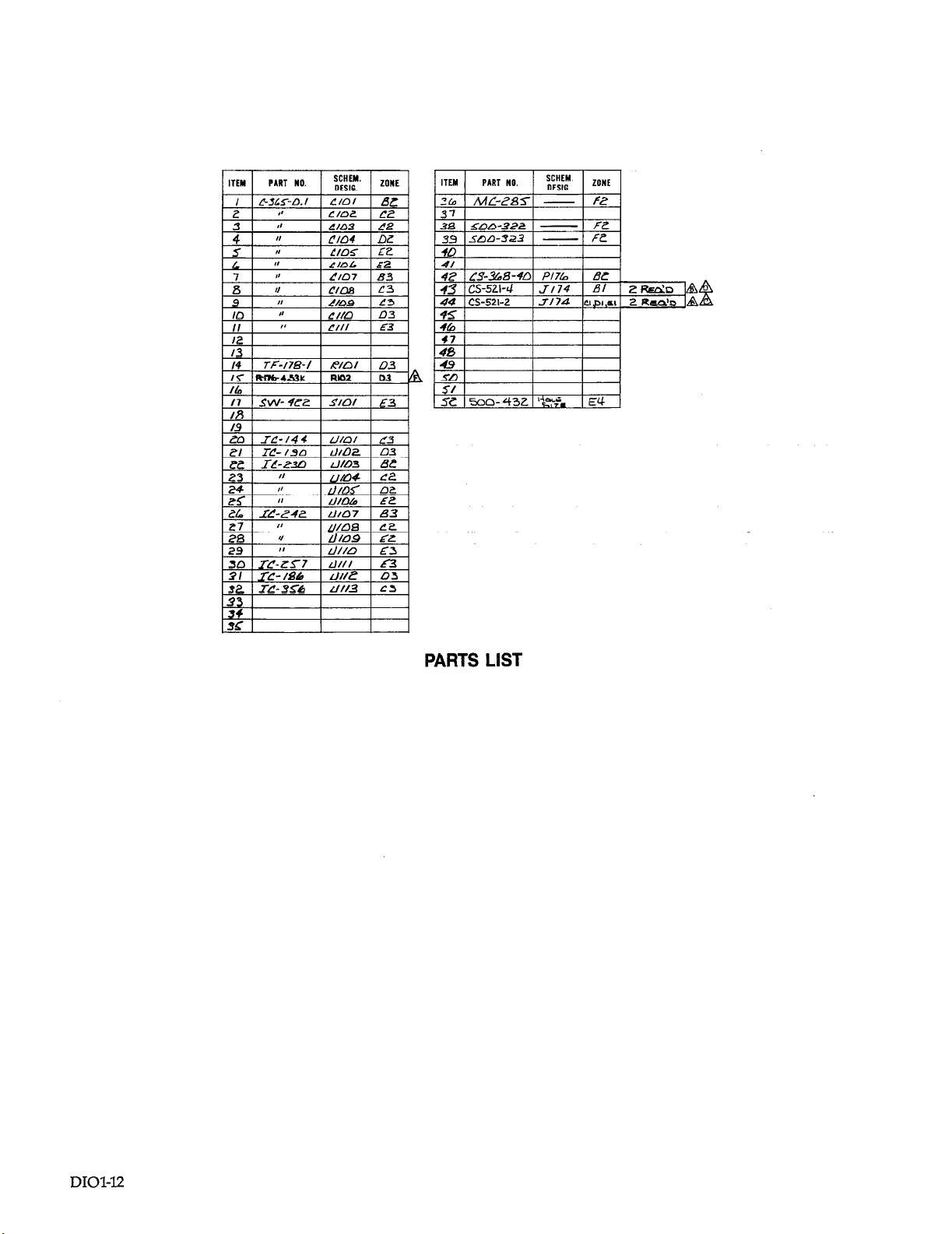
If a defective part is found, a replacement may be ordered from Keithley Data Acquisition and Control. Refer to the Service Section of the hardware manual for ordering
details. Part numbers~for the module are located on the component layout drawing
(500430).
Table 7. DIOl Troubleshooting Information
Item/
Sted Component
Required Condition
Remarks
1
DIOl Module
Channels O-31 Apply high logic level
2
SlOl
Computer Select Port A
ii
Computer Read back 255 from Port A
5
Ports B-D
6
Channels O-31 Apply low logic level
Computer Select Port A
r3
Computer
9
Ports B-D Repeat steps 8 & 9
lo
11
Slol
Computer Select Port A
12
Computer
13
Channels O-7 All outputs high
14
15
Ports B-D
Computer Select Port A
16
Computer
Channels O-7 All outputs low
F3
Ports B-D
19
Slot 10 locations: 1. lb select port: CFF92
Install in slot 10
Program ports as inputs
Repeat steps 4 & 5
Read back 0 from Port A
Program ports as outputs
Write 255 to port
Repeat steps 13 & 14
Write 0 to Port A
Repeat steps 17 & 18
2. To read/write data: CFF93
Turn power on
Apply to all inputs
All switches closed (on)
Use POKE statement
Use PEEK statement
Use POKE to select port
Apply to all inputs
Use POKE statement
Use PEEK statement
Use POKE to select port
All switches open (off)
Use POKE statement
A
Use logic probe or DMM
Use POKE to select port
Use POKE statement
Use POKE statement
Use DMM or logic probe
Use POKE statement
DIOl-9
Page 10
DlOl Specifications
Channels: 32, switch-selectable in groups of 8 for input or output
Signal Connection: Quick disconnect screw terminal blocks, plus 40 pin receptacle for
ribbon cable assembly
Input Characteristics:
TTLcompatible, high true
High-level input current: 2Ofi
Low-level input current: -0AmA
Output Characteristics:
TI’Lcompatible, high true
Drive capability:
15 standard TJYL loads
60 LS TTL loads
24mA sink at 0.5V
General: All inputs and outputs references to system ground
Accessories: Ribbons cable assembly, 6- foot, 40 conductor. One end mates with 40 pin
receptacle on DIOl, other end unterminated
DIOl-10
Page 11

Cl02 Cl03
Cl04 Cl05
Cl06
-.-.
Page 12
PART no.
. . ,
17 I
SW-922
,* I I I
SCHEM.
DEW.
I Y/Of I E-3
ZONE
4. I
3-a 15oo-.322 1 -I FZ
33 l.mn-923 1
- FZ
I
L23 I
34
SC
II
I
I
I I
I
PARTS LIST
DIOl-12
Page 13

 Loading...