

Page 1

Service Manual
DG2040
Data Generator
071-0259-50
Warning
The servicing instructions are for use by qualified
personnel only. To avoid personal injury, do not
perform any servicing unless you are qualified to
do so. Refer to all safety summaries prior to
performing service.
www.tektronix.com
Page 2

Copyright © T ektronix, Inc. All rights reserved.
T ektronix products are covered by U.S. and foreign patents, issued and pending. Information in this publication supercedes
that in all previously published material. Specifications and price change privileges reserved.
T ektronix, Inc., P.O. Box 500, Beaverton, OR 97077
TEKTRONIX and TEK are registered trademarks of T ektronix, Inc.
Page 3

WARRANTY
T ektronix warrants that the products that it manufactures and sells will be free from defects in materials and workmanship
for a period of one (1) year from the date of shipment. If a product proves defective during this warranty period, T ektronix,
at its option, either will repair the defective product without charge for parts and labor, or will provide a replacement in
exchange for the defective product.
In order to obtain service under this warranty, Customer must notify Tektronix of the defect before the expiration of the
warranty period and make suitable arrangements for the performance of service. Customer shall be responsible for
packaging and shipping the defective product to the service center designated by T ektronix, with shipping charges prepaid.
T ektronix shall pay for the return of the product to Customer if the shipment is to a location within the country in which the
T ektronix service center is located. Customer shall be responsible for paying all shipping charges, duties, taxes, and any
other charges for products returned to any other locations.
This warranty shall not apply to any defect, failure or damage caused by improper use or improper or inadequate
maintenance and care. T ektronix shall not be obligated to furnish service under this warranty a) to repair damage resulting
from attempts by personnel other than T ektronix representatives to install, repair or service the product; b) to repair
damage resulting from improper use or connection to incompatible equipment; c) to repair any damage or malfunction
caused by the use of non-T ektronix supplies; or d) to service a product that has been modified or integrated with other
products when the effect of such modification or integration increases the time or difficulty of servicing the product.
THIS WARRANTY IS GIVEN BY TEKTRONIX IN LIEU OF ANY OTHER WARRANTIES, EXPRESS OR
IMPLIED. TEKTRONIX AND ITS VENDORS DISCLAIM ANY IMPLIED WARRANTIES OF
MERCHANTABILITY OR FITNESS FOR A PARTICULAR PURPOSE. TEKTRONIX’ RESPONSIBILITY TO
REP AIR OR REPLACE DEFECTIVE PRODUCTS IS THE SOLE AND EXCLUSIVE REMEDY PROVIDED TO
THE CUSTOMER FOR BREACH OF THIS WARRANTY. TEKTRONIX AND ITS VENDORS WILL NOT BE
LIABLE FOR ANY INDIRECT , SPECIAL, INCIDENTAL, OR CONSEQUENTIAL DAMAGES IRRESPECTIVE
OF WHETHER TEKTRONIX OR THE VENDOR HAS ADVANCE NOTICE OF THE POSSIBILITY OF SUCH
DAMAGES.
Page 4

Page 5

Table of Contents
Specifications
Operating Information
General Safety Summary vii. . . . . . . . . . . . . . . . . . . . . . . . . . . . . . . . . . . .
Service Safety Summary ix. . . . . . . . . . . . . . . . . . . . . . . . . . . . . . . . . . . . .
Preface xi. . . . . . . . . . . . . . . . . . . . . . . . . . . . . . . . . . . . . . . . . . . . . . . . . . .
Contacting Tektronix xiii. . . . . . . . . . . . . . . . . . . . . . . . . . . . . . . . . . . . . . . . . . . . . .
Introduction xv. . . . . . . . . . . . . . . . . . . . . . . . . . . . . . . . . . . . . . . . . . . . . . .
Product Overview 1-1. . . . . . . . . . . . . . . . . . . . . . . . . . . . . . . . . . . . . . . . . .
Specifications 1-3. . . . . . . . . . . . . . . . . . . . . . . . . . . . . . . . . . . . . . . . . . . . . .
General Characteristics 1-3. . . . . . . . . . . . . . . . . . . . . . . . . . . . . . . . . . . . . . . . . . . .
Certification and Compliances 1-12. . . . . . . . . . . . . . . . . . . . . . . . . . . . . . . . . . . . . . .
Operating Information 2-1. . . . . . . . . . . . . . . . . . . . . . . . . . . . . . . . . . . . . .
Power Cord Information 2-2. . . . . . . . . . . . . . . . . . . . . . . . . . . . . . . . . . . . . . . . . . .
Operating Environment 2-3. . . . . . . . . . . . . . . . . . . . . . . . . . . . . . . . . . . . . . . . . . . .
Fuse T ype and Rating 2-3. . . . . . . . . . . . . . . . . . . . . . . . . . . . . . . . . . . . . . . . . . . . . .
Rear Panel Controls 2-7. . . . . . . . . . . . . . . . . . . . . . . . . . . . . . . . . . . . . . . . . . . . . . .
Applying and Interrupting Power 2-7. . . . . . . . . . . . . . . . . . . . . . . . . . . . . . . . . . . .
Repackaging Instructions 2-8. . . . . . . . . . . . . . . . . . . . . . . . . . . . . . . . . . . . . . . . . . .
Operating Instructions 2-11. . . . . . . . . . . . . . . . . . . . . . . . . . . . . . . . . . . . . .
How to Power On 2-11. . . . . . . . . . . . . . . . . . . . . . . . . . . . . . . . . . . . . . . . . . . . . . . . .
Internal Diagnostics Routines 2-11. . . . . . . . . . . . . . . . . . . . . . . . . . . . . . . . . . . . . . .
User Interface 2-12. . . . . . . . . . . . . . . . . . . . . . . . . . . . . . . . . . . . . . . . . . . . . . . . . . . .
Display Elements 2-13. . . . . . . . . . . . . . . . . . . . . . . . . . . . . . . . . . . . . . . . . . . . . . . . .
Menus 2-15. . . . . . . . . . . . . . . . . . . . . . . . . . . . . . . . . . . . . . . . . . . . . . . . . . . . . . . . . .
Pattern Storage and I/O 2-15. . . . . . . . . . . . . . . . . . . . . . . . . . . . . . . . . . . . . . . . . . . .
Loading Files 2-15. . . . . . . . . . . . . . . . . . . . . . . . . . . . . . . . . . . . . . . . . . . . . . . . . . . .
Signal Output 2-16. . . . . . . . . . . . . . . . . . . . . . . . . . . . . . . . . . . . . . . . . . . . . . . . . . . .
Theory of Operation
Module Overview 3-1. . . . . . . . . . . . . . . . . . . . . . . . . . . . . . . . . . . . . . . . . . . . . . . . .
Performance Verification
Before Running the Performance Tests 4-2. . . . . . . . . . . . . . . . . . . . . . . . . . . . . . . .
T est Procedure Notes 4-4. . . . . . . . . . . . . . . . . . . . . . . . . . . . . . . . . . . . . . . . . . . . . .
Self Tests 4-5. . . . . . . . . . . . . . . . . . . . . . . . . . . . . . . . . . . . . . . . . . . . . . . . . . . . . . .
Performance T ests 4-7. . . . . . . . . . . . . . . . . . . . . . . . . . . . . . . . . . . . . . . . . . . . . . . .
T est Record 4-43. . . . . . . . . . . . . . . . . . . . . . . . . . . . . . . . . . . . . . . . . . . . . . . . . . . . . .
Adjustment Procedures
Adjustment Procedures 5-1. . . . . . . . . . . . . . . . . . . . . . . . . . . . . . . . . . . . . .
DG2040 Service Manual
i
Page 6

Table of Contents
Maintenance
Maintenance 6-1. . . . . . . . . . . . . . . . . . . . . . . . . . . . . . . . . . . . . . . . . . . . . . .
Preparation 6-1. . . . . . . . . . . . . . . . . . . . . . . . . . . . . . . . . . . . . . . . . . . . . . . . . . . . . .
Inspection and Cleaning 6-4. . . . . . . . . . . . . . . . . . . . . . . . . . . . . . . . . . . . . . . . . . . .
Removal and Installation Procedures 6-7. . . . . . . . . . . . . . . . . . . . . . . . . .
Preparation 6-7. . . . . . . . . . . . . . . . . . . . . . . . . . . . . . . . . . . . . . . . . . . . . . . . . . . . . .
Access Procedure 6-10. . . . . . . . . . . . . . . . . . . . . . . . . . . . . . . . . . . . . . . . . . . . . . . . .
Procedures for External Modules 6-13. . . . . . . . . . . . . . . . . . . . . . . . . . . . . . . . . . . . .
Procedures for Internal Modules 6-24. . . . . . . . . . . . . . . . . . . . . . . . . . . . . . . . . . . . .
Troubleshooting 6-45. . . . . . . . . . . . . . . . . . . . . . . . . . . . . . . . . . . . . . . . . . . .
Troubleshooting Procedures 6-45. . . . . . . . . . . . . . . . . . . . . . . . . . . . . . . . . . . . . . . . .
DG2040 Data Generator Diagnostics 6-45. . . . . . . . . . . . . . . . . . . . . . . . . . . . . . . . .
Options and Accessories
Options 7-1. . . . . . . . . . . . . . . . . . . . . . . . . . . . . . . . . . . . . . . . . . . . . . . . . . . . . . . . .
Accessories 7-2. . . . . . . . . . . . . . . . . . . . . . . . . . . . . . . . . . . . . . . . . . . . . . . . . . . . . .
Replaceable Electrical Parts
Replaceable Electrical Parts 8-1. . . . . . . . . . . . . . . . . . . . . . . . . . . . . . . . . .
Diagrams
Diagrams 9-1. . . . . . . . . . . . . . . . . . . . . . . . . . . . . . . . . . . . . . . . . . . . . . . . .
Replaceable Mechanical Parts
Replaceable Mechanical Parts 10-1. . . . . . . . . . . . . . . . . . . . . . . . . . . . . . . .
Parts Ordering Information 10-1. . . . . . . . . . . . . . . . . . . . . . . . . . . . . . . . . . . . . . . . .
Using the Replaceable Parts List 10-2. . . . . . . . . . . . . . . . . . . . . . . . . . . . . . . . . . . . .
ii
DG2040 Service Manual
Page 7

List of Figures
Table of Contents
Figure 1-1: Timing definition in edge control input 1-10. . . . . . . . . . . . . . .
Figure 1-2: Transfer function for edge control input 1-11. . . . . . . . . . . . . .
Figure 1-3: Signal timing 1-11. . . . . . . . . . . . . . . . . . . . . . . . . . . . . . . . . . . .
Figure 2-1: Rear panel power switch, fuse holder,
and connector 2-5. . . . . . . . . . . . . . . . . . . . . . . . . . . . . . . . . . . . . . . . . .
Figure 2-2: Location of the ON/STBY switch 2-6. . . . . . . . . . . . . . . . . . . .
Figure 2-3: Rear panel controls 2-7. . . . . . . . . . . . . . . . . . . . . . . . . . . . . . .
Figure 2-4: Display elements 2-13. . . . . . . . . . . . . . . . . . . . . . . . . . . . . . . . .
Figure 2-5: Load Data and Parameters menu 2-16. . . . . . . . . . . . . . . . . . .
Figure 2-6: Operating buttons and menu layout 2-17. . . . . . . . . . . . . . . . .
Figure 2-7: Output voltage level and delay time display 2-19. . . . . . . . . . .
Figure 4-1: Operating buttons and menu layout 4-4. . . . . . . . . . . . . . . . .
Figure 4-2: Diagnostics menu 4-5. . . . . . . . . . . . . . . . . . . . . . . . . . . . . . . . .
Figure 4-3: Frequency measurement connections 4-8. . . . . . . . . . . . . . . .
Figure 4-4: Sequence & data output connections 4-11. . . . . . . . . . . . . . . . .
Figure 4-5: Sequence & data output timing chart 4-13. . . . . . . . . . . . . . . .
Figure 4-6: External reference input connections 4-15. . . . . . . . . . . . . . . .
Figure 4-7: Maximum operating frequency connections 4-18. . . . . . . . . . .
Figure 4-8: Maximum operating frequency (1) 4-20. . . . . . . . . . . . . . . . . .
Figure 4-9: Maximum operating frequency (2) 4-20. . . . . . . . . . . . . . . . . .
Figure 4-10: Maximum operating frequency (3) 4-21. . . . . . . . . . . . . . . . .
Figure 4-11: Maximum operating frequency connections 4-23. . . . . . . . . .
Figure 4-12: Maximum operating frequency (4) 4-25. . . . . . . . . . . . . . . . .
Figure 4-13: Maximum operating frequency (5) 4-25. . . . . . . . . . . . . . . . .
Figure 4-14: Internal trigger generator & external trigger input
connection 4-26. . . . . . . . . . . . . . . . . . . . . . . . . . . . . . . . . . . . . . . . . . . . .
Figure 4-15: Edge control mode operation connection 4-30. . . . . . . . . . . .
Figure 4-16: Edge control mode 4-31. . . . . . . . . . . . . . . . . . . . . . . . . . . . . . .
Figure 4-17: Output level measurement connections 4-32. . . . . . . . . . . . . .
Figure 4-18: Clock output amplitude measurement connection 4-35. . . . .
Figure 4-19: Delay time measurement connection 4-39. . . . . . . . . . . . . . . .
Figure 4-20: Rise time and fall time measurement connection 4-42. . . . . .
DG2040 Service Manual
Figure 6-1: DG2040 Data Generator orientation 6-9. . . . . . . . . . . . . . . . .
iii
Page 8

Table of Contents
Figure 6-2: Guide to removal procedures 6-10. . . . . . . . . . . . . . . . . . . . . . .
Figure 6-3: External modules 6-11. . . . . . . . . . . . . . . . . . . . . . . . . . . . . . . .
Figure 6-4: Internal modules 6-12. . . . . . . . . . . . . . . . . . . . . . . . . . . . . . . . .
Figure 6-5: Front-panel knob removal 6-14. . . . . . . . . . . . . . . . . . . . . . . . .
Figure 6-6: Line fuse and line cord removal 6-15. . . . . . . . . . . . . . . . . . . . .
Figure 6-7: Rear cover and cabinet removal 6-17. . . . . . . . . . . . . . . . . . . .
Figure 6-8: Front cover, trim ring, and menu button
removal (front cover not shown) 6-19. . . . . . . . . . . . . . . . . . . . . . . . . .
Figure 6-9: Front-panel module removal 6-21. . . . . . . . . . . . . . . . . . . . . . .
Figure 6-10: A12 keyboard removal 6-22. . . . . . . . . . . . . . . . . . . . . . . . . . .
Figure 6-11: Front-panel module disassembly 6-23. . . . . . . . . . . . . . . . . . .
Figure 6-12: Connector module removal 6-26. . . . . . . . . . . . . . . . . . . . . . .
Figure 6-13: Fan and fan frame removal 6-27. . . . . . . . . . . . . . . . . . . . . . .
Figure 6-14: Rear shield cover removal 6-29. . . . . . . . . . . . . . . . . . . . . . . .
Figure 6-15: Power supply module removal 6-30. . . . . . . . . . . . . . . . . . . . .
Figure 6-16: AUX power board and AC inlet removal 6-32. . . . . . . . . . . .
Figure 6-17: Monitor module removal 6-34. . . . . . . . . . . . . . . . . . . . . . . . .
Figure 6-18: CRT frame removal 6-35. . . . . . . . . . . . . . . . . . . . . . . . . . . . . .
Figure 6-19: A6 CPU board, A30 CPU Interface board
and A40 Clock board removal 6-37. . . . . . . . . . . . . . . . . . . . . . . . . . . .
Figure 6-20: A50 PG & Output board removal 6-39. . . . . . . . . . . . . . . . . .
Figure 6-21: A16 Back plane board removal 6-41. . . . . . . . . . . . . . . . . . . .
Figure 6-22: Battery location on the A16 Back plane board 6-43. . . . . . . .
Figure 6-23: Floppy-disk drive module removal 6-44. . . . . . . . . . . . . . . . .
Figure 6-24: A6 CPU Board 6-46. . . . . . . . . . . . . . . . . . . . . . . . . . . . . . . . . .
Figure 6-25: Primary troubleshooting procedure 1 6-47. . . . . . . . . . . . . . .
Figure 6-26: Primary troubleshooting procedure 2 6-48. . . . . . . . . . . . . . .
Figure 6-27: Power Supply module troubleshooting procedure 6-49. . . .
Figure 6-28: AUX Power board 6-50. . . . . . . . . . . . . . . . . . . . . . . . . . . . . . .
Figure 6-29: Power Supply module 6-50. . . . . . . . . . . . . . . . . . . . . . . . . . . .
Figure 6-30: A6 CPU Board or front-panel module
troubleshooting procedure 6-51. . . . . . . . . . . . . . . . . . . . . . . . . . . . . . .
Figure 6-31: Key board 6-52. . . . . . . . . . . . . . . . . . . . . . . . . . . . . . . . . . . . . .
Figure 6-32: Monitor module troubleshooting procedure 6-53. . . . . . . . . .
Figure 6-33: Monitor module 6-54. . . . . . . . . . . . . . . . . . . . . . . . . . . . . . . . .
Figure 6-34: Horizontal and vertical sync signals 6-54. . . . . . . . . . . . . . . .
Figure 6-35: A video signal with white and black levels 6-55. . . . . . . . . . .
Figure 6-36: A30 CPU Interface board, A40 Clock board
or A50 PG & Output board troubleshooting procedure 6-56. . . . . . . .
iv
DG2040 Service Manual
Page 9

Table of Contents
Figure 6-37: Module isolation troubleshooting procedure 6-57. . . . . . . . .
Figure 9-1: DG2040 block diagram 9–3. . . . . . . . . . . . . . . . . . . . . . . . . . . .
Figure 9-2: DG2040 interconnect diagram 9–4. . . . . . . . . . . . . . . . . . . . . .
Figure 10-1: Cabinet 10-5. . . . . . . . . . . . . . . . . . . . . . . . . . . . . . . . . . . . . . . .
Figure 10-2: Main chassis and CRT 10-7. . . . . . . . . . . . . . . . . . . . . . . . . . .
Figure 10-3: Main chassis and circuit boards 10-9. . . . . . . . . . . . . . . . . . . .
Figure 10-4: Circuit boards 10-11. . . . . . . . . . . . . . . . . . . . . . . . . . . . . . . . . .
Figure 10-5: Front panel assembly 10-13. . . . . . . . . . . . . . . . . . . . . . . . . . . .
DG2040 Service Manual
v
Page 10

Table of Contents
List of Tables
Table 1-1: Electrical characteristics 1-3. . . . . . . . . . . . . . . . . . . . . . . . . . .
Table 1-2: Period JItter 1-8. . . . . . . . . . . . . . . . . . . . . . . . . . . . . . . . . . . . .
Table 1-3: Cycle to Cycle JItter 1-8. . . . . . . . . . . . . . . . . . . . . . . . . . . . . . .
Table 1-4: Mechanical characteristics 1-8. . . . . . . . . . . . . . . . . . . . . . . . .
Table 1-5: Environmental characteristics 1-8. . . . . . . . . . . . . . . . . . . . . .
Table 1-6: Certifications and compliances 1-12. . . . . . . . . . . . . . . . . . . . . .
Table 2-1: Power-cord conductor identification 2-2. . . . . . . . . . . . . . . . .
Table 2-2: Power cord identification 2-2. . . . . . . . . . . . . . . . . . . . . . . . . . .
Table 2-3: Fuse and fuse cap part numbers 2-4. . . . . . . . . . . . . . . . . . . . .
Table 2-4: AC line power requirements 2-4. . . . . . . . . . . . . . . . . . . . . . . .
Table 2-5: DG2040 Data Generator display elements 2-14. . . . . . . . . . . . .
Table 4-1: Performance check disk files 4-2. . . . . . . . . . . . . . . . . . . . . . . .
Table 4-2: Required equipment 4-3. . . . . . . . . . . . . . . . . . . . . . . . . . . . . . .
Table 4-3: Error codes 4-6. . . . . . . . . . . . . . . . . . . . . . . . . . . . . . . . . . . . . .
Table 4-4: Internal clock frequency accuracy 4-10. . . . . . . . . . . . . . . . . . .
Table 4-5: High level output voltage accuracy 4-34. . . . . . . . . . . . . . . . . .
Table 4-6: Low level output voltage accuracy 4-34. . . . . . . . . . . . . . . . . . .
Table 4-7: Clock output voltage accuracy 4-37. . . . . . . . . . . . . . . . . . . . . .
Table 4-8: Rise and fall time accuracies 4-43. . . . . . . . . . . . . . . . . . . . . . .
Table 4-9: DG2040 test record 4-44. . . . . . . . . . . . . . . . . . . . . . . . . . . . . . . .
Table 6-1: Relative susceptibility to static-discharge damage 6-3. . . . . .
Table 6-2: External Inspection Check List 6-4. . . . . . . . . . . . . . . . . . . . . .
Table 6-3: Internal inspection check list 6-5. . . . . . . . . . . . . . . . . . . . . . . .
Table 6-4: Equipment required 6-8. . . . . . . . . . . . . . . . . . . . . . . . . . . . . . .
Table 7-1: International Power Cords 7-1. . . . . . . . . . . . . . . . . . . . . . . . .
Table 7-2: Standard accessories 7-2. . . . . . . . . . . . . . . . . . . . . . . . . . . . . .
Table 7-3: Optional accessories 7-3. . . . . . . . . . . . . . . . . . . . . . . . . . . . . . .
vi
DG2040 Service Manual
Page 11

General Safety Summary
Review the following safety precautions to avoid injury and prevent damage to
this product or any products connected to it. To avoid potential hazards, use this
product only as specified.
Only qualified personnel should perform service procedures.
To Avoid Fire or
Personal Injury
Use Proper Power Cord. Use only the power cord specified for this product and
certified for the country of use.
Connect and Disconnect Properly. Do not connect or disconnect probes or test
leads while they are connected to a voltage source.
Ground the Product. This product is grounded through the grounding conductor
of the power cord. To avoid electric shock, the grounding conductor must be
connected to earth ground. Before making connections to the input or output
terminals of the product, ensure that the product is properly grounded.
Observe All Terminal Ratings. To avoid fire or shock hazard, observe all ratings
and markings on the product. Consult the product manual for further ratings
information before making connections to the product.
Do Not Operate Without Covers. Do not operate this product with covers or panels
removed.
Use Proper Fuse. Use only the fuse type and rating specified for this product.
Avoid Exposed Circuitry. Do not touch exposed connections and components
when power is present.
Do Not Operate With Suspected Failures. If you suspect there is damage to this
product, have it inspected by qualified service personnel.
DG2040 Service Manual
Do Not Operate in Wet/Damp Conditions.
Do Not Operate in an Explosive Atmosphere.
Keep Product Surfaces Clean and Dry.
Provide Proper Ventilation. Refer to the manual’s installation instructions for
details on installing the product so it has proper ventilation.
vii
Page 12
General Safety Summary
Symbols and Terms
Terms in this Manual. These terms may appear in this manual:
WARNING. Warning statements identify conditions or practices that could result
in injury or loss of life.
CAUTION. Caution statements identify conditions or practices that could result in
damage to this product or other property.
Terms on the Product. These terms may appear on the product:
DANGER indicates an injury hazard immediately accessible as you read the
marking.
WARNING indicates an injury hazard not immediately accessible as you read the
marking.
CAUTION indicates a hazard to property including the product.
Symbols on the Product. The following symbols may appear on the product:
WARNING
High Voltage
Protective Ground
(Earth) Terminal
CAUTION
Refer to Manual
Double
Insulated
viii
DG2040 Service Manual
Page 13

Service Safety Summary
Only qualified personnel should perform service procedures. Read this Service
Safety Summary and the General Safety Summary before performing any service
procedures.
Do Not Service Alone. Do not perform internal service or adjustments of this
product unless another person capable of rendering first aid and resuscitation is
present.
Disconnect Power. To avoid electric shock, disconnect the mains power by means
of the power cord or, if provided, the power switch.
Use Caution When Servicing the CRT. To avoid electric shock or injury, use
extreme caution when handling the CRT. Only qualified personnel familiar with
CRT servicing procedures and precautions should remove or install the CRT.
CRTs retain hazardous voltages for long periods of time after power is turned off.
Before attempting any servicing, discharge the CRT by shorting the anode to
chassis ground. When discharging the CRT, connect the discharge path to ground
and then the anode. Rough handling may cause the CRT to implode. Do not nick
or scratch the glass or subject it to undue pressure when removing or installing it.
When handling the CRT, wear safety goggles and heavy gloves for protection.
Use Care When Servicing With Power On. Dangerous voltages or currents may
exist in this product. Disconnect power, remove battery (if applicable), and
disconnect test leads before removing protective panels, soldering, or replacing
components.
To avoid electric shock, do not touch exposed connections.
XĆRadiation. To avoid x-radiation exposure, do not modify or otherwise alter the
high-voltage circuitry or the CRT enclosure. X-ray emissions generated within
this product have been sufficiently shielded.
DG2040 Service Manual
ix
Page 14

Service Safety Summary
x
DG2040 Service Manual
Page 15

Introduction
This manual contains information needed to properly service the DG2040 Data
Generator, as well as general information critical to safe and effective servicing.
To prevent personal injury or damage to the DG2040 Data Generator, consider
the following before attempting service:
H The procedures in this manual should be performed only by a qualified
service person
H Read the General Safety Summary and the Service Safety Summary,
beginning on page vii
H Read the Operating Information section beginning on page 2-1
When using this manual for servicing be sure to follow all warnings, cautions,
and notes.
Performance Verification Interval
Generally, the performance verification should be done every 12 months and is
recommended after the replacement of a module.
Strategy for Servicing
If the DG2040 Data Generator does not meet performance criteria, repair is
necessary.
This manual contains all the information needed for periodic maintenance of the
DG2040 Data Generator. (Examples of such information are procedures for
checking performance.)
Further, the manual contains all information for corrective maintenance at the
module level. To isolate a failure to a module, use the troubleshooting procedures found in Maintenance:Troubleshooting section, beginning on page 6-1. To
remove and replace any failed module, follow the instructions in the Mainte-
nance:Removal and Installation Procedures beginning on page 6-15. After
isolating a faulty module, replace it with a fully-tested module obtained from
your local Tektronix distributor or sales office. The Replaceable Mechanical
Parts section, beginning on page 10-1, contains part number and ordering
information for all replaceable modules.
DG2040 Service Manual
xi
Page 16

Introduction
Tektronix Service Offerings
Tektronix provides service to cover repair under warranty as well as other
services that may provide a cost-effective answer to your service needs.
Whether providing warranty repair service or any of the other services listed
below, Tektronix service technicians are well trained to service the DG2040 Data
Generator. They have access to the latest information on improvements to the
DG2040 Data Generator as well as the latest new options.
Warranty Repair Service
Self Service
Tektronix warrants this product for one year from date of purchase. The warranty
appears on the back of the title page in this manual. Tektronix technicians
provide warranty service at most Tektronix service locations. The Tektronix
product catalog lists all worldwide service locations.
Tektronix supports repair to the module level by providing Module Exchange.
Module Exchange. This service reduces down-time for repair by allowing you to
exchange most modules for remanufactured ones. Each module comes with a
90-day service warranty.
For More Information. Contact your local Tektronix service center or sales
engineer for more information on any of the repair or adjustment services just
described.
xii
DG2040 Service Manual
Page 17

Preface
Manual Structure
This is the service manual for the DG2040 Data Generator. The manual contains
information needed to service the data generator to the module level.
This manual is divided into sections, such as the Specification and Theory of
Operation. Some sections are divided into subsections, such as Product
Description and Removal and Installation Procedures.
Sections containing procedures also contain introductions to those procedures.
Be sure to read these introductions because they provide information needed to
do the service correctly and efficiently. Following is a brief description of each
manual section.
H The Specification section contains a description of the DG2040 Data
Generator and the characteristics that apply to it.
H The Operating Information section includes general information and
operating instructions.
H The Theory of Operation section contains circuit descriptions that support
service to the module level.
H The Performance Verification section contains procedures to verify that the
DG2040 Data Generator functions properly and meets warranted limits.
H The Adjustment Procedure section contains a statement explaining that no
adjustment is needed for the DG2040 Data Generator.
H The Maintenance section contains information and procedures to perform
preventive and corrective maintenance of the DG2040 Data Generator. These
instructions include cleaning, module removal and installation, and fault
isolation to the module.
H The Options section contains information for servicing factory-installed
options.
H The Replaceable Electrical Parts section contains a statement that refers you
to the Replaceable Mechanical Parts. Both the electrical and mechanical
replaceable parts are listed in the mechanical section.
H The Diagrams section contains block diagrams and an interconnect diagram.
H The Replaceable Mechanical Parts. section includes a table of all replace-
able modules, their descriptions, and their Tektronix part numbers.
DG2040 Service Manual
xiii
Page 18

Preface
Manual Conventions
This manual uses certain conventions that you should become familiar with.
Some sections of the manual contain procedures for you to perform. To keep
those instructions clear and consistent, this manual uses the following
conventions:
H Names of front panel controls and menus appear in the same case (initial
capitals, all uppercase, etc.) in the manual as is used on the DG2040 Data
Generator front panel and menus. Front panel names are all upper-case
letters; for example, SETUP MENU, HARDCOPY, etc.
H Instruction steps are numbered unless there is only one step.
Modules
Safety
Throughout this manual, any replaceable component, assembly, or part of the
DG2040 Data Generator is referred to generically as a module. In general, a
module is an assembly (like a circuit board), rather than a component (like a
resistor or an integrated circuit). Sometimes a single component is a module. For
example, the chassis of the DG2040 Data Generator is a module.
Symbols and terms related to safety appear in the Safety Summary near the
beginning of this manual.
Finding Other Information
Other documentation for the DG2040 Data Generator includes:
H The DG2040 Data Generator User Manual contains a tutorial that explains
H The DG2040 Data Generator Programmer Manual explains how to use a
how to operate the DG2040 Data Generator. Also included is instructions
explaining how to use other DG2040 Data Generator features.
GPIB or RS-232 interface to remotely control the DG2040 Data Generator.
xiv
DG2040 Service Manual
Page 19

Contacting Tektronix
Preface
Phone 1Ć800Ć833Ć9200*
Address Tektronix, Inc.
Department or name (if known)
14200 SW Karl Braun Drive
P.O. Box 500
Beaverton, OR 97077
USA
Web site www.tektronix.com
Sales support 1Ć800Ć833Ć9200, select option 1*
Service support 1Ć800Ć833Ć9200, select option 2*
Technical support Email: techsupport@tektronix.com
1Ć800Ć833Ć9200, select option 3*
6:00 a.m. - 5:00 p.m. Pacific time
* This phone number is toll free in North America. After office hours, please leave a
voice mail message.
Outside North America, contact a Tektronix sales office or distributor; see the
Tektronix web site for a list of offices.
DG2040 Service Manual
xv
Page 20

Preface
xvi
DG2040 Service Manual
Page 21

Product Overview
The DG2040 Data Generator is a portable digital data generator designed for
high performance and ease of use. The DG2040 Data Generator is easy to use for
testing and evaluating semiconductors and logic circuits, which are continually
becoming faster and more complex. The DG2040 Data Generator provides high
performance and a wide range of functions in a compact package.
Main Features
Following are the main features of the DG2040 Data Generator :
H Maximum data rate of 1.1 GHz
H 256 K word pattern memory
H Flexible sequence looping (which does the equivalent of over a billion word
H Two channels (Complementary)
H For each output channel:
patterns)
H Variable output levels (from –1.125 to +3.5 V, into 50 W)
H Edge Control function (CH0 only)
H Delay setting (–1.0 ns to +2.0 ns, 10 ps resolution)
H Serial/Parallel pattern editing
Any memory size from 360 words to 256 K words can be used easily with no
restrictions within that range. Either of the two bit data channels can be assigned
to any output channel. The output channels support setting of high and low
output voltage levels, and delay time. CH0 supports edge position.
The DG2040 Data Generator also provides a 4000-step sequence controller,
which enables the generation of not only a data pattern longer than the pattern
memory but also dynamic pattern change triggered by external events.
The DG2040 Data Generator provides flexible data editing functions, including
word and line unit input and extended data creation functions. The DG2040 Data
Generator also provides functions that are required for system construction, such
as a sequencing function which is a jump function using external input.
DG2040 Service Manual
1Ć1
Page 22

Product Overview
Applications
Following are some of the DG2040 Data Generator applications:
H Supports subassembly and system testing by simulating the digital signals
from incomplete sections of a product
H Performs margin tests by using the DG2040 Data Generator to generate
patterns that have a low probability of occurrence or are difficult to generate
H Constructs interactive digital simulation systems by using the sequence
output, external jump, and tristate control functions
H Uses flexible data output functions to make the DG2040 Data Generator an
ideal data generator for simulation of semiconductor devices and drivers
specific to serial data communication and all types of digital circuits
H Performs various timing analysis and jitter/wander tests by using the edge
control function to generate jitter on all the edges or selected edge(s)
1Ć2
DG2040 Service Manual
Page 23

Specifications
General Characteristics
This section describes the general characteristics of the DG2040 Data Generator.
All specifications are guaranteed unless labeled “typical”. Typical specifications
are provided for your convenience but are not guaranteed. Specifications marked
with the √ symbol are checked in the performance verification procedure
beginning on page 4-1.
The certification and compliances for the DG2040 Data Generator are found at
the end of this appendix.
Performance Conditions
Table 1Ć1: Electrical characteristics
Characteristics Description
Operation mode
Repeat Pattern data is repeatedly output. When a sequence is specified, patterns are repeated
Single Pattern data is output only once. When a sequence is specified, a trigger signal outputs
Step Pattern data is output based on the clock, not specified by the clock source, but generated by
Enhanced Pattern data is output completely according to a sequence. All extended sequence functions,
1
The electrical characteristics are valid under the following conditions:
H The instrument must be in an environment with temperature, altitude,
humidity, and vibration within the operating limits described in these
specifications.
H The instrument must have had a warm-up period of at least 20 minutes.
H The instrument must have been calibrated and adjusted at an ambient
temperature between +20
H The instrument must be operating at an ambient temperature between
+10_ C to +40_ C, unless otherwise noted.
according to the sequence order. The extended sequence functions such as trigger wait, event
jump, and so on are ignored in this mode.
according to the sequence order.
pressing the STEP/EVENT button on the front panel. This mode is the same as the Repeat
mode except for the clock.
such as trigger wait, and event jump, are valid in this mode. This mode is the same as the
Repeat mode except for the extended sequence functions.
_ C and +30_ C.
DG2040 Service Manual
1Ć3
Page 24

Appendix A: Specifications
Table 1Ć1: Electrical characteristics (Cont.)
Characteristics Description
Output pattern
Pattern length 360 to 262144 points
Number of channels 2 Channels, Complementary
Sequence Maximum 4000 steps
Number of blocks Maximum 256
Internal trigger generator
Internal trigger rate
Range 1.0 ms to 10.0 s
Resolution 3 digits, 0.1 ms min.
Accuracy ± 0.01 %
Clock generator
√ Internal clock
Frequency 0.1 Hz to 1.1 GHz
Resolution 7 digits
Accuracy ± 0.0001 %, 1 year after shipment from factory
Data and clock out
Connectors CH0, CH0, CH1, CH1. (SMA connectors at front panel)
√ Output voltage
Accuracy
Maximum Output Current ± 100 mA
Aberration
Overshoot
Undershoot
√ Rise/fall time (20% to 80%)
√ Channel skew
1, 2
CLOCK OUT, CLOCK OUT
(SMA connector at rear panel)
All outputs are complementary.
DC (data out) (± 3 % of setting) ± 50 mV (into 50 W)
Amplitude (clock
(± 5 % of setting) ± 50 mV (into 50 W)at1MHz
out)
t 5%at1.5V
t 5%at1.5V
t 150 ps at 1 V
at 10 MHz
pĆp
at 10 MHz
pĆp
at 10 MHz, measured with a 0.5 m (20 inches), 50 W cable. See Optional
pĆp
Accessories on page 7Ć3 for details.
t ± ( | 25° C-Ta| × 15 ps ± 100 ps), where Tais the ambient temperature °C.
1Ć4
At 10 MHz, 1.0 V high, 0 V low, in Repeat Mode, the pattern is Clock except when using the
Edge Control function.
DG2040 Service Manual
Page 25

Appendix A: Specifications
Table 1Ć1: Electrical characteristics (Cont.)
Characteristics Description
Period jitter Measured by TDS694C-1MHD with TDSJIT1
(typical) Refer to Table 1Ć2.
Cycle to cycle jitter Measured by TDS694C-1MHD with TDSJIT1
(typical) Refer to Table 1Ć3.
√ Delay function
Delay channel CH0 (CH0), and CH1 (CH1),
Delay time -1.0 ns to +2.0 ns
Resolution 10 ps
Accuracy
Output impedance (typical) 50 W
Output voltage
High level (VOH) -1.75 V to +7.00 V (into 1 MW)
Low level (VOL) -2.25 V to +6.50 V (into 1 MW)
Resolution 10 mV (into 1 MW)
Voltage swing (VOH-VOL) 0.5 V to 5 V (into 1 MW)
Event input
Connector BNC at rear panel
Threshold level -5.0 V to +5.0 V, +1.4 V at default
Resolution 0.1 V
Input impedance (typical) 1kW
Turning point for event jump 230.5 to 254.5 clocks before the next block. Refer to Tacin Figure 1Ć3 on page 1Ć11.
Maximum input voltage ± 5V
Polarity Positive (rising edge)
Minimum pulse width
Sensitivity
t(± 3 % of setting) ± |25° C-Ta| × 15 ps ± 100 ps, where Tais the ambient temperature °C.
At 10 MHz, 1.0 V high, 0 V low, in Repeat Mode, the pattern is Clock except when using the
Edge Control function.
-0.875ĂV to +3.5 V (into 50 W)
-1.125 V to +3.25 V (into 50 W)
5 mV (into 50 W)
0.25 V
pĆp
to 2.5 V
(into 50 W)
pĆp
y 100 ns
y 1.0 V
pĆp
DG2040 Service Manual
1Ć5
Page 26

Appendix A: Specifications
Table 1Ć1: Electrical characteristics (Cont.)
Characteristics Description
Event output
Connector BNC at rear panel
Level
High level (Vhi) Approximately5Vinto1MW
Approximately 2.5 V into 50 W
Low level (Vlo) Approximately 0 V into both 1 MW and 50 W
Delay time 194.5 to 214.5 clocks before data output change. Refer to Td5in Figure 1Ć3 on page 1Ć11.
Pulse width 180 to 200 clocks. Refer to PW2in Figure 1Ć3 on page 1Ć11.
Impedance 50 W
Sync output
Connector BNC at rear panel
Level (typical)
High level (VOH) Approximately 5 V (into 1 MW)
Approximately 2.5 V (into 50 W)
Low level (VOL) Approximately 0 V (into both 1 MW and 50 W)
Trigger Input (typical)
Delay time from external trigger
input signal (typical)
Delay time to clock out and
data out (typical)
Pulse width (typical) 32 or 36 clocks. Refer to PW1in Figure 1Ć3 on page 1Ć11.
Impedance (typical) 50 W
Trigger input
Connector BNC at front panel
Threshold level -5.0 V to +5.0 V, +1.4 V at default
Resolution 0.1 V
Threshold accuracy (± 5 % of setting) ± 0.1 V
Minimum pulse width
Sensitivity
Impedance 50 W ± 2 W
Polarity Positive or Negative
Maximum input ± 10Vinto1kW
Trigger holdoff Minimum 100 ns
55 ns + 8/F
x Td1x 55 ns + 12/F
clk (GHz)
clk (GHz)
(Typical)
Internal Reference. Refer to Td1in Figure 1Ć3 on page 1Ć11.
1.5 Clocks, Refer to Td2in Figure 1Ć3 on page 1Ć11.
y 10 ns
y 0.5 V
pĆp
1kW ± 100 W
± 5 V into 50 W
1Ć6
DG2040 Service Manual
Page 27

Table 1Ć1: Electrical characteristics (Cont.)
Characteristics Description
Reference 10 MHz clock input
Connector BNC at front panel
Input voltage range 0.2 V to 3.0 V
Input voltage level
"Ă10 V Max
Impedance 50 W, AC Coupling
FrequencyĂRange 10ĂMHzñĂ0.1ĂMHz
Edge control input
Connector BNC at front panel
Voltage Range (typical) -Ă1Vto+1V
Input Impedance (typical) 50ĂW
Frequency Range (typical) DC to less than 500 MHz (-3 dB)
Transfer Function (typical) See Figure 1Ć2 on page 1Ć11.
Display
Display area Width: 13.2 cm (5.2 inches)
Height: 9.9 cm (3.9 inches)
Resolution Horizontal: 640 pixels
Vertical: 480 pixels
AC line power
Rating Voltage 100Ć240 V AC
Voltage Range and
Frequency Range
90Ć250 V AC, Input voltage frequency range is 48 Hz to 63 Hz
90Ć127 V AC, Input voltage frequency range is 48 Hz to 440 Hz
Maximum power 300 W
Maximum current 4A
Fuse rating 6A FAST, 250 V, UL 198G ( 3AG )
pĆp
Appendix A: Specifications
5A(T),250V,IEC127
1
Clock outputs continuously regardless of the operation mode.
2
The data output duty cycle varies from 3:7 to 7:3 at 1.0 V
pĆp
clock continuously outputs regardless of the run mode or sequence.
DG2040 Service Manual
during the 10 ms just after the output has been started. The
1Ć7
Page 28
Appendix A: Specifications
Table 1Ć2: Period JItter
Clock frequency 1.1 GHz 800 MHz
Measurement StdDev Pk-Pk StdDev Pk-Pk
Clock output 3.0 ps 16 ps 3.0 ps 13 ps
CH0 output 3.5 ps 20 ps 3.5 ps 20 ps
Table 1Ć3: Cycle to Cycle JItter
Clock frequency 1.1 GHz 800 MHz
Measurement StdDev Pk-Pk StdDev Pk-Pk
Clock output 5.0 ps 28 ps 4.0 ps 22 ps
CH0 output 5.5 ps 32 ps 5.5 ps 32 ps
Table 1Ć4: Mechanical characteristics
Characteristics Description
Net weight
Standard 10.3 kg (22.7 lb)
Dimensions
Height 164 mm (6.4 inches) including feet
Width 362 mm (14.3 inches) including handle
Length 491 mm (19.25 inches) including front cover
576 mm (22.2 inches) with handle extended
Table 1Ć5: Environmental characteristics
Characteristics Description
Temperature
Operating +10_ Cto+40_ C
Nonoperating -20_ Cto+60_ C
Relative humidity
Operating 20% to 80% (No condensation)
Maximum wetĆbulb temperature 29.4_ C
Nonoperating 5% to 90% (No condensation)
Maximum wetĆbulb temperature 40.0_ C
1Ć8
DG2040 Service Manual
Page 29

Table 1Ć5: Environmental characteristics (Cont.)
Characteristics Description
Altitude
Operating To 4.5 km (15,000 feet).
Maximum operating temperature decreases 1 _C each 300 m above 1.5 km.
Nonoperating To 15 km (50,000 feet).
Dynamics
Vibration
Operating 0.27 G
Nonoperating 2.28 G
Shock
Nonoperating 294 m/s2(30 G), halfĆsine, 11 ms duration.
Three shocks per axis in each direction (18 shocks total)
Installation requirements
Power consumption 300 watts maximum. Maximum line current is 4 A
Dissipation (fully loaded) 90 V line, with 5% clipping
Surge current
x 9 A peak for less than 5 line cycles at 25_ C after product has been off for at least 30 s.
Cooling clearance
Top clearance 2.5 cm (1 inch)
Side clearance 15 cm (6 inches)
Rear clearance 7.5 cm (3 inches)
, 5 to 500 Hz
rms
, 5 to 500 Hz
rms
rms
Appendix A: Specifications
at 50 Hz
DG2040 Service Manual
1Ć9
Page 30
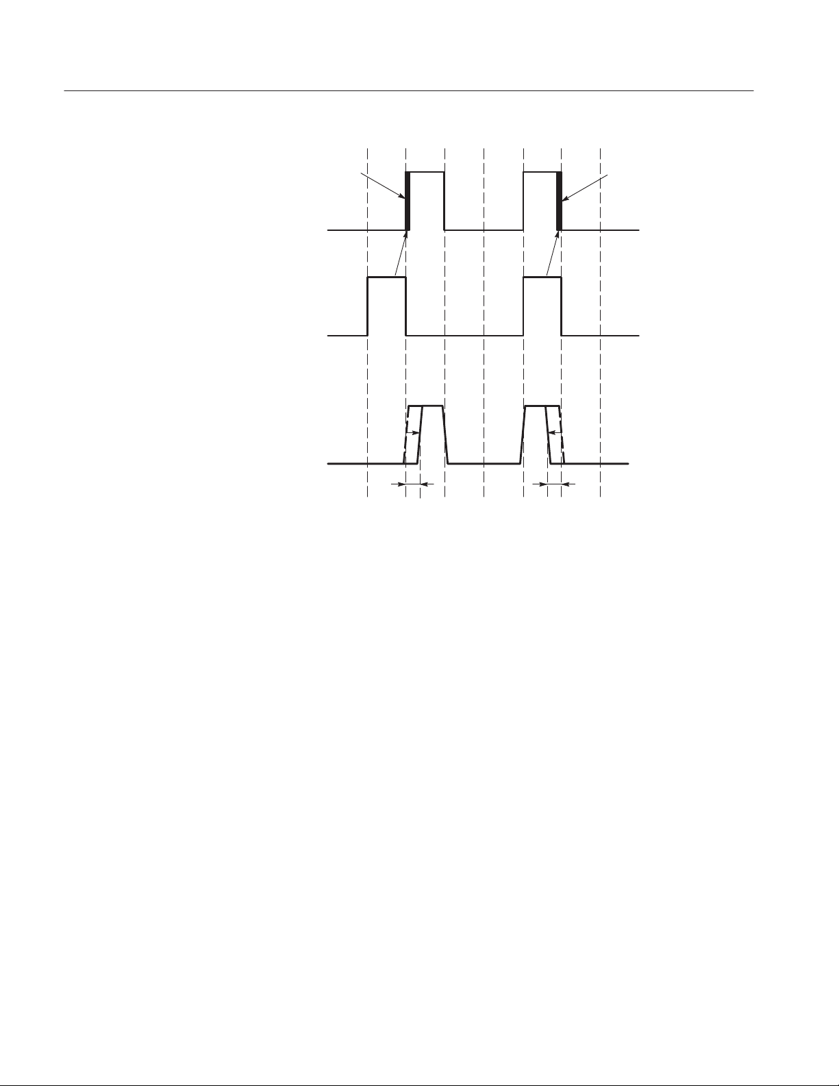
Appendix A: Specifications
Controlled Edge
CH0 Pattern
CH1 Pattern
CH0 Output
11
00 00
11
000000
ntr
The rising edge moves to the right and falling edge moves to the left, when the
position offset is set to more than 0 ps or when the edge control input is more
than 0V.
Controlled Edge
00
ntf
Figure 1Ć1: Timing definition in edge control input
1Ć10
DG2040 Service Manual
Page 31

Appendix A: Specifications
300
Rising Edge
Falling Edge
200
100
0
-100
Position Offset [ps]
-200
-300
-1.5
-1 -0.5 0 0.5 1 1.5
Edge Control Input [V]
Figure 1Ć2: Transfer function for edge control input
External
trigger input
Clock output
Data output
Sync output
Data output
Event input
Event input
Event output
Start
D1N D20 D10 D22 D23 D24 D25 D26 D27 D28
T
d1
Current block Next block
P
w2
T
ac
(Td5)
T
Stop
D2NĆ3 D2NĆ2 D2NĆ1
P
w1
d2
(Typical) 55 ns + 8/F
x Td1x 55 ns + 12/F
clk (GHz)
Td2= 1.5 clocks (typical)
= 32 to 36 clocks
P
w1
T
) = 194.5 to 214.5 clocks
ac(Td5
= 180 to 200 clocks
P
w2
Jump to the specified block after the current block
Jump to the specified block after the next block
D2NĆ2
clk (GHz)
Figure 1Ć3: Signal timing
DG2040 Service Manual
1Ć11
Page 32

Appendix A: Specifications
Certification and Compliances
The certification and compliances for the DG2040 Data Generator are listed in
Table 1-6.
Table 1Ć6: Certifications and compliances
Category Standards or description
EC Declaration of Conformity EMC
Australian/New Zealand
declaration of Conformity Ć EMC
EC Declaration of Conformity Low Voltage
Meets intent of Directive 89/336/EEC for Electromagnetic Compatibility. Compliance was
demonstrated to the following specifications as listed in the Official Journal of the European
Communities:
EMC Directive 89/336/EEC:
EN 55011
Class A Radiated and Conducted Emissions
EN 50081Ć1 Emissions:
EN61000Ć3Ć2
AC Power Line Harmonic Emissions
EN 50082Ć1 Immunity:
EN61000Ć4Ć2
Electrostatic Discharge Immunity
EN61000Ć4Ć3
RF Electromagnetic Field Immunity
EN61000Ć4Ć4
Electrical Fast Transient/Burst Immunity
EN61000Ć4Ć6
Conducted Disturbance Induced by Radio-frequency Field
EN61000Ć4Ć8
Power Frequency Electromagnetic Field Immunity
EN61000Ć4Ć11
Voltage Dips and Interruptions Immunity
Complies with EMC provision of Radio-communications Act per the following standard:
AS/NZS 2064.1/2 Industrial, Scientific, and Medical Equipment: 1992
Compliance was demonstrated to the following specification as listed in the Official Journal of the
European Communities:
Low Voltage Directive 73/23/EEC, amended by 93/68/EEC
EN 61010Ć1/A1:1992
Safety requirements for electrical equipment for
measurement, control and laboratory use.
Approvals Complies with the following safety standards:
UL3111-1, First Edition Standard for electrical measuring and test equipment.
CAN/CSA C22.2 No.1010.1Ć92
Safety requirements for electrical equipment for
measurement, control and laboratory use.
1Ć12
DG2040 Service Manual
Page 33

Appendix A: Specifications
Table 1Ć6: Certifications and compliances (cont.)
Category Standards or description
Installation Category Description Terminals on this product may have different installation (over-voltage) category designations. The
installation categories are:
Category Examples of products in this category
CAT III DistributionĆlevel mains (usually permanently connected). Equipment at this
level is typically in a fixed industrial location.
CAT II LocalĆlevel mains (wall sockets). Equipment at this level includes appliances,
portable tools, and similar products. Equipment is usually cordĆconnected.
CAT I Secondary (signal level) or battery operated circuits of electronic equipment.
Pollution Degree A measure of the contaminates that could occur in the environment around and within a product.
Typically the internal environment inside a product is considered to be the same as the external.
Products should be used only in the environment for which they are rated.
Pollution Degree 2 Normally only dry, nonconductive pollution occurs. Occasionally a
temporary conductivity that is caused by condensation must be
expected. This location is a typical office/home environment.
Temporary condensation occurs only when the product is out of
service.
Conditions of Approval Safety Certifications/Compliances are made for the following conditions:
Altitude (maximum operation): 2000 meters
IEC Characteristics Equipment type:
Test and Measuring
Installation Category II (as defined in IEC 61010-1, Annex J)
Pollution Degree 2 (as defined in IEC 61010-1)
Safety Class I (as defined in IEC 61010-1, Annex H)
DG2040 Service Manual
1Ć13
Page 34

Appendix A: Specifications
1Ć14
DG2040 Service Manual
Page 35

Operating Information
Page 36

Page 37

Operating Information
This subsection provides the following information:
H Operating environment
H Supplying operating power
H Applying and interrupting power
H Checking the fuse
NOTE. Read all information and heed all warnings in this subsection before
connecting the DG2040 Data Generator to a power source.
Refer to the Specification section of this manual for line voltage and frequency
ranges.
WARNING. To avoid equipment failure and potential fire or personal shock
hazards, do not exceed the maximum rated operating voltage of 250 V between
the voltage-to-ground (earth) and either pole of the power source. The DG2040
Data Generator operates from a single-phase power source and has a three-wire
power cord with a two-pole, three-terminal grounding plug. Also, before making
connection to the power source, be sure the DG2040 Data Generator has a
suitable two-pole, three-terminal grounding-type plug.
DG2040 Service Manual
To avoid personal shock hazard, do not touch conductive parts. All accessible
conductive parts are directly connected through the grounding conductor of the
power cord to the grounded (earth) contact of the power plug. The DG2040
Data Generator is safety Class 1 equipment (IEC designation).
WARNING. To avoid personal shock hazard, do not defeat the grounding
connection. Insert the power input plug only in a mating receptacle with a
grounding contact where earth ground has been verified by a qualified service
person. Also, for electrical shock protection, make the grounding connection
before making connection to the DG2040 Data Generator input or output
terminals.
2Ć1
Page 38

Operating Information
Power Cord Information
The DG2040 Data Generator is shipped with the required power cord as ordered
by the customer. Table 2-1 gives the color-coding of the conductors in the power
cord. Table 2-2 shows information on the available power cords.
Table 2Ć1: PowerĆcord conductor identification
Conductor Color Alternate color
Ungrounded (Line) Brown Black
Grounded (Neutral) Light Blue White
Grounded (Earthing) Green/Yellow Green
Table 2Ć2: Power cord identification
Plug configuration Normal usage Option number
North America
125 V
Europe
230 V
United Kingdom
230 V
Australia
230 V
North America
230 V
Switzerland
230 V
Standard
A1
A2
A3
A4
A5
2Ć2
DG2040 Service Manual
Page 39

Operating Environment
Operating Information
To ensure proper DG2040 Data Generator operation and long life, note the
following environmental requirements.
CAUTION. Damage to the instrument can occur if this instrument is powered on
at temperatures outside the specified temperature range.
NOTE. If you are installing the instrument in a dedicated rack, refer to the
instruction sheet that comes with the rack mounting kit for proper installation
procedures.
Operating Temperature
Ventilation Requirements
Fuse Type and Rating
The DG2040 Data Generator operates correctly in ambient temperatures from
+10_ C to +40_ C and in relative humidity from 20% to 80%.
Verify that there is at least 2.5 cm (1 inch) of clearance on top and bottom, 15.0
cm (6 inches) on the left and right sides, and 7.5 cm (3 inches) at the rear of the
instrument to allow for heat dissipation. Verify that the air intake holes on the
sides and bottom of the cabinet are not obstructed.
The feet on the bottom of the DG2040 Data Generator cabinet provide the
required clearance when it is set on a flat surface.
CAUTION. To prevent temporary shutdown of the DG2040 Data Generator, do
not restrict air flow through the chassis. If the DG2040 Data Generator shuts
down unexpectedly, improve ventilation around the DG2040 Data Generator and
wait a few minutes to allow it to cool down; then switch the power on again.
The DG2040 Data Generator uses the same fuse for all operating line voltage
ranges. One of two fuse types is installed in the instrument, depending upon the
power cord option. Table 2-3 provides the available types and ratings.
DG2040 Service Manual
WARNING. To avoid electrical shock, always unplug the power cord from the
socket before checking the line fuse.
2Ć3
Page 40

Operating Information
Check Fuse
Check the fuse to be sure it is the proper type and rating.
To check the fuse, remove the fuse holder on the rear panel. Refer to Figure 2-3
for the location of the fuse holder. To remove the fuse holder, turn it counterclockwise with a screwdriver while pushing it in.
WARNING. To avoid electrical shock, be sure that the power cord is disconnected
before checking the fuse.
Use a slotted screwdriver to remove the fuse. Push in and turn the fuse holder
cap counterclockwise. See Figure 2-1 for the fuse location.
The instrument order specified either a UL approved or an IEC approved fuse.
Each fuse requires its own cap. See Table 2-3.
Table 2Ć3: Fuse and fuse cap part numbers
Tektronix fuse
Fuse
0.25 inch × 1.25 inch (UL 198.6, 3 AG):
6 A fast, 250
5mm× 20 mm (IEC 127): 5 A (T), 250 V 159Ć0210Ć00 200Ć2265Ć00
part number
159Ć0239Ć00 200Ć2264Ć00
Tektronix fuse cap
part number
Check Voltage Settings
Connect Power Cable
NOTE. The second fuse listed in Table 2-3 is approved under the IEC standards.
This fuse is used in equipment sold in the European market.
Check that you have the proper electrical connections. Refer to Table 2-4 for
power requirements.
Table 2Ć4: AC line power requirements
Name Description
Line voltage range 90 V - 250 V
Line frequency 48 Hz - 440 Hz ( 90 V - 127 V)
48 Hz - 63 Hz (127 V - 250 V)
Maximum power 300 W
Connect the proper power cord from the rear panel power connector to the power
system. Refer to Table 2-2 for power cord identification.
2Ć4
DG2040 Service Manual
Page 41

Operating Information
CAUTION. The instrument is shipped with a power cord appropriate for use with
your power systems (normal 115 V power system or 230 V power system). If the
instrument is to be used with a power system other than what the order specified,
the power cord must be replaced with one appropriate for the power source
used.
Standby Power
Apply power to the standby circuit of the instrument by pushing the
PRINCIPAL POWER SWITCH on the rear panel of the instrument. Refer to
Figure 2-1.
NOTE. After the instrument is installed, leave the PRINCIPAL POWER
SWITCH on and use the ON/STBY switch as the power switch.
Power Connector
Power On
DG2040 Service Manual
Fuse PRINCIPAL POWER
SWITCH
Figure 2Ć1: Rear panel power switch, fuse holder, and connector
Press the ON/STBY switch on the lower left side of the front panel to power on
the instrument. Refer to Figure 2-2.
Verify that the fan is operating.
2Ć5
Page 42

Operating Information
NOTE. Allow a 20 minute warm-up period prior to calibrating the clock for the
instrument to operate at its optimum precision.
StartĆUp Diagnostics
Power Off
ON/STBY Switch
Figure 2Ć2: Location of the ON/STBY switch
The DG2040 Data Generator automatically runs diagnostics when the instrument
is powered on from the ON/STBY switch. These diagnostics check whether the
instrument is performing within its defined operating characteristics. If all the
diagnostic items have been completed without error, the instrument displays the
EDIT menu.
NOTE. If the instrument chassis temperature is outside the specified operating
range, an error will occur during the power-up diagnostics. If this happens,
power off the instrument, wait until the chassis temperature is within normal
operating range, and then power on the instrument again.
If an error is displayed, contact your Tektronix Field Office or representative.
To power off the DG2040 Data Generator, press the ON/STBY switch.
2Ć6
DG2040 Service Manual
Page 43

Rear Panel Controls
Operating Information
NOTE. The ON/STBY switch disables the outputs of the power supply. The
PRINCIPAL POWER SWITCH on the rear panel disconnects the instrument
from the primary voltage source.
Figure 2-3 shows the rear panel controls for the DG2040 Data Generator.
Power Connector
Figure 2Ć3: Rear panel controls
Applying and Interrupting Power
Consider the following information when you power on or power off the
DG2040 Data Generator, or when external power loss occurs.
PowerĆon Cycle
DG2040 Service Manual
At power-on, the start-up diagnostics check the DG2040 Data Generator
operation. If all diagnostic items complete without error, the DG2040 Data
Generator displays the EDIT menu.
Fuse PRINCIPAL POWER
SWITCH
2Ć7
Page 44

Operating Information
If the diagnostics detect an error, the DG2040 Data Generator displays the error
code. To exit the diagnostics menu, press any key; then the system displays the
EDIT menu. See the Maintenance:Troubleshooting section, beginning on page
6-1 for information on diagnostics and fault isolation.
NOTE. If the ambient temperature goes outside the specified operating temperature range, an error occurs during the diagnostics at power-on. If this happens,
power off the DG2040 Data Generator and wait until the chassis temperature is
appropriate; then switch the power on again.
PowerĆoff Cycle
Memory Backup Power
Wait for the DG2040 Data Generator to finish the operation when saving data
files. Improper power-off or unexpected loss of power to the DG2040 Data
Generator can result in the corruption of data stored in nonvolatile memory.
A lithium battery maintains internal nonvolatile memory, allowing the DG2040
Data Generator to retain data files if AC power is lost. This battery has a shelf
life of about three years. Partial or total loss of stored information at power-on
may indicate that the battery needs to be replaced.
WARNING. To avoid risk of fire or explosion, replace the DG2040 Data
Generator battery with a lithium battery having the part number listed in the
Replaceable Mechanical Parts section beginning on page 10-10.
To avoid risk of fire or explosion, do not recharge, rapidly discharge, or
disassemble the battery; and do not incinerate the battery or heat it above
100° C. Also, dispose of used batteries promptly. Small quantities of used
batteries can be disposed of in normal refuse. Keep lithium batteries away from
children.
Repackaging Instructions
If this instrument is shipped by commercial transportation, use the original
packaging material. If the original packaging is unfit for use or is not available,
repackage the instrument as follows:
1. Obtain a corrugated cardboard shipping carton having inside dimensions at
2Ć8
least six inches greater than the instrument dimensions and having a carton
test strength of at least 124.74 kg (275 pounds).
DG2040 Service Manual
Page 45

Operating Information
2. If the instrument is being shipped to a Tektronix Service Center for repair or
calibration, attach a tag to the instrument showing the following: owner of
the instrument (with address), the name of a person at your firm who may be
contacted if additional information is needed, complete instrument type and
serial number, and a description of the service required.
3. Wrap the instrument with polyethylene sheeting or equivalent to protect the
outside finish and prevent entry of packing materials into the instrument.
4. Cushion the instrument on all sides by tightly packing dunnage or urethane
foam between the carton and the instrument, allowing for three inches of
padding on each side (including top and bottom).
5. Seal the carton with shipping tape or with an industrial stapler.
DG2040 Service Manual
2Ć9
Page 46

Operating Information
2Ć10
DG2040 Service Manual
Page 47

Operating Instructions
Before servicing the DG2040 Data Generator, read the following operating
instructions. These instructions are at the level appropriate for servicing the
DG2040 Data Generator. The user manual contains complete operator instructions.
How to Power On
The Performance Verification section, begining on page **
instructions for making the front-panel settings required to check DG2040 Data
Generator characteristics.
To power-on the DG2040 Data Generator, follow these steps:
1. Set the PRINCIPAL POWER SWITCH (on the rear of the DG2040 Data
Generator) to the ON position. This switch is the main power switch; it
routes power to the standby circuit in the DG2040 Data Generator.
2. Press the ON/STBY (standby) switch on the front (lower-left corner) of the
DG2040 Data Generator. This switch applies power to the remaining circuits
of the DG2040 Data Generator. Allow at least 20 minutes for the DG2040
Data Generator to warm up.
WARNING. To avoid personal shock hazard, turn off both the ON/STBY switch
and the PRINCIPAL POWER SWITCH before servicing. The PRINCIPAL
POWER SWITCH on the rear panel is the true power disconnect switch. The
ON/STBY (standby) switch simply toggles operation on and off. When connected
to a power source and when the PRINCIPAL POWER SWITCH is on, the
internal power supplies and much of the other circuitry of the DG2040 Data
Generator remain energized regardless of the setting of the ON/STBY switch.
**, includes
To avoid personal shock hazard, set the PRINCIPAL POWER SWITCH off
before connecting or disconnecting the line cord to or from the power source.
Internal Diagnostics Routines
At power-on, the DG2040 Data Generator performs internal start-up diagnostics.
These diagnostics check the internal circuit function and report any failures. In
addition, you can initiate internal diagnostics using the Diag item in the
UTILITY menu; these diagnostics differ from the start-up diagnostics in that
they do more extensive memory checking.
DG2040 Service Manual
2Ć11
Page 48

Operating Instructions
User Interface
The DG2040 Data Generator uses a combination of front-panel buttons, keys, a
knob, and on-screen menus to control generator functions. Some front-panel
controls select menus and manipulate menu items. Others enter values and units,
allow manual triggering, start/stop DG2040 Data Generator output, advance the
pattern data, generate an event pulse, and make a hard copy. On-screen graphics
show various aspects of the current DG2040 Data Generator configuration.
On-screen menus set most DG2040 Data Generator functions. Main menus
provide access to lower-level submenus. Buttons in the center of the front panel
select the main menus.
When you select a menu, the display shows the items controlled by that menu
and numeric values currently in effect. Buttons around the display select
lower-level menus, change menu selections, modify numeric values and units,
and execute functions.
2Ć12
DG2040 Service Manual
Page 49

Operating Instructions
Display Elements
Figure 2-4 shows the display elements, including bottom and side menus, work
area, status lines, and so on. Also shown are a pop-up menu and message box.
Table 2-5 describes each element in detail.
1 2
6
3
5
Figure 2Ć4: Display elements
4
7
8
DG2040 Service Manual
2Ć13
Page 50

Operating Instructions
Table 2Ć5: DG2040 Data Generator display elements
Figure
number
1 Status area
Label Description
Displays the current status of the instrument. This status
line is always displayed, whichever menu is displayed.
The status line displays the following two items.
MODE: Displays the run mode in which pattern data will
be output.
UPDATE: Displays the update method for pattern data
output when data is updated.
In addition, there is also a disk icon that indicates
whether or not a floppy disk is inserted in the disk drive.
A clock icon may also be displayed at the left end of the
status line. When this icon is displayed, the instrument is
busy with internal processing and cannot accept other
inputs.
2 Date and Time
display area
3 Side menu Related side menu items are displayed here when a
4 Bottom menu When one of the buttons in the menu section is pressed,
5 Button function
description
area
6 Message disĆ
play area
7 PopĆup mesĆ
sage box
8 PopĆup menu The instrument sometimes displays a popĆup menu
The date and time display can be turned on or off using
the UTILITY menu.
bottom menu item is selected. The topmost entry in the
side menu displays either a label representing the side
menu or the operation name for the confirmed item.
the corresponding bottom menu is displayed. When a
bottom menu item is selected the corresponding side
menu is displayed. Selecting the same bottom menu
item again closes the side menu.
Displays descriptions of the functions of the front panel
buttons.
Displays messages that report on the current processing
state. This area can be also used by remote commands
to display user messages.
When required, the instrument temporarily displays a
window at the center of the screen to display a warning
or question for the user.
when a bottom menu or side menu item is selected.
Enter a numeric value or select an item using either the
general purpose knob or the front panel buttons.
2Ć14
DG2040 Service Manual
Page 51

Menus
Operating Instructions
The DG2040 Data Generator operation is primarily controlled by means of
menus that correspond to the EDIT, SETUP, APPLICATION and UTILITY
buttons in the MENU column. To display one of these main menus on the
screen, push the corresponding button. The button LED indicates which menu is
currently selected. Refer to the DG2040 Data Generator User Manual for more
details concerning these menus.
H EDIT Menu
Provides functions for editing pattern data and creating sequences.
H SETUP Menu
Provides functions for defining groups, setting up channels, and setting
output channel voltages, the operating mode, and triggers.
H APPLICATION Menu
The current version of the firmware provides edge control functions under
the APPLICATION menu.
Pattern Storage and I/O
Loading Files
H UTILITY Menu
This menu provides functions for manipulating the basic instrument settings.
The DG2040 Data Generator has internal nonvolatile memory (NVRAM) for
pattern file storage. The DG2040 Data Generator generates patterns from files
residing in internal nonvolatile memory.
The DG2040 Data Generator also has a floppy-disk drive for loading files from a
floppy disk into internal nonvolatile memory, and for saving files from memory
to a floppy disk. The disk drive accepts 3.5-inch floppy disks in the MS-DOS
format.
The following steps explain how to load files from a floppy disk into internal
memory.
1. Turn the disk so the side with the arrow is on top; insert the disk into the
DG2040 Data Generator floppy disk drive.
DG2040 Service Manual
2. Press the EDIT button on the front panel.
2Ć15
Page 52

Operating Instructions
3. Select File from the bottom menu.
4. Select Load Data & Setup from the side menu. The menu in Figure 2-5
appears.
5. Turn the general purpose knob to highlight the file you want to load and
select OK from the sub menu.
6. Push the floppy drive button and remove the disk from the floppy drive.
Signal Output
2Ć16
Figure 2Ć5: Load Data and Parameters menu
The procedure assumes that data has already been loaded as explained in the
previous section.
The following example first groups the data bits from the pattern data already
created and allocates each data bit to output channels. Next, this procedure sets
all the settings required for signal output and actually outputs the signals.
DG2040 Service Manual
Page 53

Operating Instructions
H Tables such as the one below shows the sequence of the operating procedure.
Execute the action on the left side of the top row first. Then execute actions
from left to right across the row. When one row has been completed, move to
the left side of the next row down. For pop-up menus, use the general
purpose knob to select items from the menu list. Operations such as
Operation 6 (below) do not involve pressing the buttons shown in the row
above, but rather are descriptions of operations to be performed. Figure 2-6
shows the buttons used and the menu layout.
Front panel
Menu button Bottom button PopĆup menu Side button
Operation 1 Operation 2 Operation 3 Operation 4 Operation 5
Operation 6 (For example, set to xx with general purpose knob.)
Operation 7
button
Setting Sampling Clock
Frequency
PopĆup Menu
Bottom Menu
Side Menu
Bottom Button
General Purpose Knob
Menu Button
Side Button
Figure 2Ć6: Operating buttons and menu layout
1. Set the sampling clock frequency to 800 MHz.
Menu button Bottom button PopĆup menu Side button
Clock Source
(Select Int)
Front Panel Button
Front panel
button
DG2040 Service Manual
Int FREQ 800
MHz
2Ć17
Page 54

Operating Instructions
Setting Signal Generation
Mode
Setting Output Level
2. Set the signal generation mode to continuous mode.
Front panel
Menu button Bottom button PopĆup menu Side button
Run Mode Repeat
button
The output level is always at the TTL level.
3. Set the output channel CH0 and CH1 output levels to 2 V for the high level
and –1 V for the low level.
Front panel
Menu button Bottom button PopĆup menu Side button
Level Condition
Select channel CH0 using the front panel up and down arrow buttons.
High Level 2
Low Level -1
button
ENTER
ENTER
Setting Delay Timing
Set the output levels for channels CH1 to CH7 in the same manner.
The delay time for each channel can be set.
4. Set the delays for the output channel CH0 and CH1 to 2 ns.
Front panel
Menu button Bottom button PopĆup menu Side button
Select channel CH1 by pressing the front panel up and down arrow buttons.
Delay 10
Set the delays for channels CH5 to CH7 in the same manner.
button
ENTER
2Ć18
DG2040 Service Manual
Page 55

Delay Time Setting
Output Voltage Level Settings
Figure 2Ć7: Output voltage level and delay time display
Operating Instructions
Signal Output
This step actually outputs the signals.
5. Press the START/STOP button on the front panel.
DG2040 Service Manual
2Ć19
Page 56

Operating Instructions
2Ć20
DG2040 Service Manual
Page 57

Theory of Operation
This section describes the basic operation of the major circuit blocks or modules
in the DG2040 Data Generator. The Diagrams section, beginning on page 9-1,
includes a block diagram and an interconnect diagram. Figure 9-1 shows the
modules and functional blocks of the DG2040 Data Generator. Figure 9-2 shows
how the modules interconnect.
Module Overview
The module overview describes the basic operation of each functional circuit
block.
The DG2040 Data Generator consists of two major electrical sections; the Main
Frame section and the PG (Pulse Generator) & Output section. The Main Frame
section consists of Clock Board, CPU Board, Back Plane, Bezel Switch, Display
Monitor, Power Supply, Auxiliary Power Supply, FDD (Floppy Disk Drive), and
Fan. The PG & Output section consists of PG circuitry and Output circuitry.
Main Frame Section
The Main Frame section consists of the following modules and components.
Clock Board (A30). The clock board contains the clock generator, trigger circuit,
and miscellaneous control circuit for the PG and Output board. This trigger
signal is provided from the connector on the front panel.
CPU BoardĂ(A6). The CPU board receives commands from the front panel or the
GPIB/RS-232-C interface and controls the PG section through the Back Plane
board. It also sends the video signal to the display monitor for displaying various
graphical menus, data pattern figures, message texts, etc. The CPU board
contains MPU, ROM, RAM, video display, bus timing circuitry, and the
interfaces to GPIB, RS-232-C, FDD, and the front panel.
CAUTION. To avoid losing pattern data files stored in NVRam, save the files to a
floppy disk before removing the A6 CPU board or A16 Back plane board. Then
restore the files from floppy disk to the DG2040 Data Generator nonvolatile
memory after installing the new board(s).
Back Plane Board (A16). The DG2040 Data Generator back plane has five slots
which accommodate the CPU board and Clock board. This board receives
DG2040 Service Manual
3Ć1
Page 58

Theory of Operation
power from the Power Supply module and distributes the power to the boards in
the slots. This board also interconnects various lines such as the CPU buses and
other control signals.
Power Supply. The power supply module receives the filtered line power from
Auxiliary Power board and sends regulated voltages to the Back Plane board.
The module supplies the following voltages: +5 V, –4.6 V, –2 V, +15 V,
and –15 V.
This module features a remote control with the ON/STBY switch on the bezel.
The remote switching signal which is generated on the bezel is sent to the CPU
board by the Back Plane board. The signal is transformed by the CPU board and
sent to the Power Supply by way of the Back Plane.
Front Panel (A6, CPU Board). The front panel contains menu buttons, LEDs, a
rotary encoder and so on, for entering selections. User selections from the front
panel are sent to the processor. This interface is compatible with TDS series
oscilloscope. Commands from the processor control the LED in the buttons.
Display Monitor (A6, CPU Board). The Display Monitor consists of a raster scan
CRT and its driver circuitry. It receives the sync and video signals from the CPU
board and +15 V DC power from the Power Supply. The Display Monitor is
serviced as a module; no adjustment procedure or circuit description is provided.
Bezel Switch. The buttons at the bottom and side of the display are bezel
switches. This is a flexible circuit which is sealed in the chassis.
Auxiliary Power Supply (A100). The Auxiliary Power Supply consists of a main
power switch, a fuse, and AC power.
GPIB (A6, CPU Board). This functional block is the General Purpose Interface Bus
(GPIB) interface drive, which controls communication with external devices
over the parallel interface. The GPIB connector is on the rear panel.
RSĆ232C (A6, CPU Board). This functional block is the RS-232-C interface circuit
which controls serial communication with external devices over the RS-232-C
interface. The RS-232-C interface connector is on the rear panel.
Floppy Disk Drive. The 3.5-inch floppy disk drive supports both 2DD and 2HD
MS-DOS formats.
3Ć2
DG2040 Service Manual
Page 59

Theory of Operation
Fan. This is a brushless DC fan which draws approximately 0.5 A from +12 V.
The fan prevents heat build-up inside the cabinet; it pulls air into the right
(floppy-disk) side of the DG2040 Data Generator and exhausts air out the left
side.
PG & Output Section
The PG (Pulse Generator) & Output Section consists of the following circuit
blocks.
PG Circuitry (A50, PG & Output Board). The PG circuitry is the core of the
DG2040 Data Generator and consists of the pattern memory, shift register, and
address generator. The sequence of the output pattern is controlled by the address
generator. This block receives the system clock from the Clock board and sends
the digital pattern data to the Output circuit.
Output Circuit (A50, PG & Output Board). The output circuitry contains the Pin
Driver, edge control circuit and the delay control circuit. The Pin Driver outputs
the digital pattern and converts the signal levels for various types of logics such
as TTL, CMOS, LVCOMS, ECL, and PECL. It also has the ability of changing
the output signal edge control (CH0 only). This block contains the data latch
clock signal. This signal generated by the Pin Driver is the same as data outputs,
the signal levels can be converted like data outputs.
DG2040 Service Manual
3Ć3
Page 60

Theory of Operation
3Ć4
DG2040 Service Manual
Page 61

Performance Verification
Two types of performance tests can be performed on this product. You may not
need to perform all of these procedures, depending on what you want to
accomplish.
H Self test
The DG2040 Data Generator incorporates a diagnostic system that performs
comprehensive instrument testing. This system verifies that the DG2040
Data Generator is operating correctly. The self tests execute quickly and
require no special equipment during execution.
H Performance test
The performance test verifies the operation of the items that are marked with
a (√) symbol in Appendix A:Specifications. The equipment listed in Table
4-2 is required to perform these performance tests.
DG2040 Service Manual
4Ć1
Page 62

Performance Verification
Before Running the Performance Tests
Do the following before running the performance tests:
Warm Up
File Loading
A 20 minute warm up period is required prior to running the operation tests.
The performance check disk provided with the DG2040 Data Generator includes
the files listed in Table 4-1. The specified file must be loaded into the DG2040
Data Generator for each operation test item. These files include pattern data and
setup information.
Table 4Ć1: Performance check disk files
File name Operation test
TP1CLK.PDA Internal clock frequency
TP2PG.PDA Sequence and data output
TP3EXREF.PDA External reference input
TP4CONT.PDA Maximum operating frequency (Continuous)
TP5TRIG.PDA Maximum operating frequency (Trigger operation)
TP6GEN.PDA Internal trigger generator and external trigger input
TP7EDGE.PDA Edge control mode
TP8LVL.PDA Data output level
TP9PULSE.PDA Clock output amplitude
TP10DLY.PDA Delay time
TP11RISE.PDA Rise and fall time
4Ć2
Follow the procedure below to load the file required by a performance test into
the instrument:
1. Insert the performance check disk into the DG2040 Data Generators floppy
disk drive.
2. Select EDIT ! File ! Load Data & Setup.
3. Select the required file using the general purpose knob.
4. Select OK from the submenu.
DG2040 Service Manual
Page 63

Performance Verification
Required Equipment
Table 4-2 lists the equipment required for the performance tests.
Table 4Ć2: Required equipment
Item No. Required precision Recommended equipment
Frequency counter 1 Frequency range: 0.1 Hz to 1250 MHz
Precision: 7 digits or higher
Digital multimeter 1 DC voltage range: ±10 V
Precision: 0.01 V
Performance check disk 1 Tektronix part no. 063Ć3121ĆXX
Oscilloscope 1 Bandwidth: 1 GHz or higher Tektronix TDS784D
Sampling oscilloscope with
head
Function generator 1 Amplitude: 4 V, offset: 2 V
BNC cable 5 Impedance: 50 W
SMA cable 5 Impedance: 50 W
SMA female-to-BNC male
adapter
Precision 50 W termination 1 Impedance: 50 W (0.1 %) Tektronix part no. 011Ć0129Ć00
SMA X5 attenuatorĂ(14ĂdB) 3 Tektronix part no. 015Ć1002Ć00
NĆtoĆBNC adapter 1 Tektronix part no. 103Ć0045Ć00
BNCĆdualĆbanana adapter 1 Tektronix part no. 103Ć0090Ć00
50 W SMA termination 2 Tektronix part no. 015Ć1022Ć00
1 Bandwidth: 6 GHz or higher Tektronix 11801C with head SDĆ22
(50 W termination),
Frequency: 1 MHz or higher
Length: 24 inches
Length: 20 inches
2 Tektronix part no. 015Ć0572Ć00
ANRITSU MF 1603A
Tektronix DM2510
(provided with the DG2040 Data Generator)
Tektronix AFG320
Tektronix part no. 012Ć1342Ć00
Tektronix part no. 174Ć1427Ć00
DG2040 Service Manual
4Ć3
Page 64

Performance Verification
Test Procedure Notes
The following conventions are used in this section for describing the self tests
and performance tests.
H The test items are described in the following order.
H Characteristic tested
H Required equipment
H Connections
H Test procedure
H The test procedure is presented in order starting with step 1, and progresses
through the end of the procedure. Tables such as the one shown below appear
in these steps. For these steps, press the buttons in the order shown in the
table, either from left to right or from top to bottom, to select the required
menu item. For pop-up menus, use the general purpose knob to select items
from the menu list. Operations such as Operation 6 do not involve pressing
the buttons shown in the row above, but rather are descriptions of operations
to be performed. Figure 4-1 shows the buttons used and the menu layout.
Front panel
Menu button Bottom button Pop up menu Side button
Operation 1 Operation 2 Operation 3 Operation 4 Operation 5
Operation 6 (for example, insert a disk in the disk drive.)
Operation 7
PopĆup Menu
Bottom Menu
Side Menu
General Purpose Knob
Front Panel Buttons
Menu ButtonsBottom Buttons Side Buttons
button
Figure 4Ć1: Operating buttons and menu layout
4Ć4
DG2040 Service Manual
Page 65

Self Tests
Performance Verification
Execute the DG2040 Data Generator self tests and verifies that no errors
occurred.
1. Press the required buttons in the following order. Selecting All from the
Type side button causes the instrument to run the self-test on all test items.
Front panel
Menu button Bottom button Pop up menu Side button
UTILITY Diag Type (Select All)
Execute
2. Verify that all self tests passed by checking the Status display area shown in
Figure 4-2.
button
DG2040 Service Manual
Figure 4Ć2: Diagnostics menu
If Fail is listed in the Status display area, an error code will be displayed in
the Comment column. See Table 4-3 for the meanings of the error codes.
NOTE. Contact your Tektronix sales representative if an error occurs.
4Ć5
Page 66

Performance Verification
Table 4Ć3: Error codes
Error code Error meaning Failed component
1XX CPU diagnostics error A6 CPU board
2XX Display diagnostics error A6 CPU board
3XX Front panel diagnostics error A12 Key board
4XX Clock diagnostics error A40 Clock board
5XX Trigger diagnostics error A40 Clock board
6XX Sequence memory diagnostic error A50 PG & Output board
7XX Pattern memory diagnostics error A50 PG & Output board
4Ć6
DG2040 Service Manual
Page 67

Performance Tests
Performance Verification
The performance test for the DG2040 Data Generator must be completed in the
following order:
1. Internal clock frequency
2. Sequence and data output
3. External reference input
4. Maximum operating frequency
5. Internal trigger generator and external trigger input
6. Edge control mode operation
7. Output level accuracy
8. Clock output amplitude accuracy
9. Delay time accuracy
Internal Clock Frequency
10. Rise and fall time accuracy
This test verifies the frequency accuracy of the internal clock of the DG2040
Data Generator.
The following equipment is required.
Equipment Required Frequency counter
Two SMA cables
Two 50 W terminations
Two SMA femaleĆtoĆBNC male adapters
NĆtoĆBNC adapter
Performance check disk
DG2040 Service Manual
4Ć7
Page 68

Performance Verification
Connections. Refer to Figure 4-3 for connections.
Use the N-to-BNC adapter, an SMA female-to-BNC male adapter, and an SMA
cable to make the following connection:
H Connect the CLOCK output from the DG2040 Data Generator rear panel to
the frequency counter input (INPUT B).
Use the second SMA cable, the second female-to-BNC male adapter, and the
50 W termination to make the following connection:
H Terminate the CLOCK
DG2040 Data Generator
output.
CLOCK
CLOCK
SMA Cable
SMA femaleĆtoĆBNC male adapter
and 50 W termination
Frequency Counter
NĆtoĆBNC adapter and
SMA femaleĆtoĆBNC
male adapter
Figure 4Ć3: Frequency measurement connections
Setup. Set the frequency counter to frequency measurement mode.
Procedure. Follow the steps below to verify the accuracy of the internal clock
frequencies:
4Ć8
1. Load the TP1CLK.PDA test pattern file from the performance check disk.
When the file is loaded, the DG2040 Data Generator clock frequency will be
set to 1100 MHz internally.
NOTE. Refer to Table 4-4 for steps 2 through 5.
2. Perform the following steps to check the 1.100000 GHz clock frequency
accuracy:
a. Press the START/STOP button on the front panel. The LED corre-
sponding to the button should be on.
DG2040 Service Manual
Page 69

Performance Verification
b. Set the counter trigger to an appropriate value and verify that the counter
displays a frequency in the range of 1.09999989 to 1.1000011 GHz.
Refer to Table 4-4.
3. Perform the following steps to check the 650.1000 MHz clock frequency
accuracy:
a. Press the following buttons to set the DG2040 Data Generator clock
frequency to 650.1 MHz.
Front panel
Menu button Bottom button Pop up menu Side button
SETUP Clock Int FREQ 650.1
button
MHz/ms
b. Set the counter trigger to an appropriate value, and verify that the
counter displays a frequency in the 650.09935 MHz to 650.10065 MHz
range.
4. Perform the following steps to check the 200.0000 kHz clock frequency
accuracy:
a. Change the frequency counter input to INPUT A through the 50 W
termination with the SMA cable.
b. Set the DG2040 Data Generator clock frequency to 200 kHz.
c. Set the counter trigger to an appropriate value, and verify that the
counter displays a frequency in the 199.99980 kHz to 200.00020 kHz
range.
5. Perform the following steps to check the 100.0000 mHz clock frequency
accuracy:
a. Set the DG2040 Data Generator clock frequency to 100 mHz (0.1 Hz).
b. Set the counter trigger to an appropriate value, and verify that the
counter displays a frequency in the range 99.99990 mHz to 100.00010
mHz
.
DG2040 Service Manual
4Ć9
Page 70

Performance Verification
Table 4Ć4: Internal clock frequency accuracy
Internal clock frequencies Clock frequency ranges
1.100000 GHz 1.0999989 GHz 1.1000011 GHz
650.1000 MHz 650.09935 MHz 650.10065 MHz
200.0000 kHz 199.99980 kHz 200.00020 kHz
100.0000 mHz (10.0 s) 99.99990 mHz 100.00010 mHz
6. Press the START/STOP button on the front panel to stop the output (the
buttons LED goes off).
Sequence & Data Output
This test verifies that the pattern data that is output from the DG2040 Data
Generator output channel ports (CH0, CH0
, CH1, and CH1) is functioning
correctly.
The following equipment is required.
Equipment Required Oscilloscope
Function generator
Three BNC cables
Two SMA cables
Two SMA femaleĆtoĆBNC male adapters
Performance check disk
Connections. Refer to Figure 4-4 for connections.
Use the SMA cables and the SMA female-to-BNC male adapters to make the
following connections:
H Connect CH0 output from the DG2040 Data Generator front panel to the
oscilloscope CH1 input.
4Ć10
H Connect CH0
output from the DG2040 Data Generator front panel to the
oscilloscope CH2 input.
Use the BNC cables to make the following connections:
H Connect the function generator CH1 output to the DG2040 Data Generator
rear panel event input.
H Connect the event output from the DG2040 Data Generator rear panel to the
oscilloscope CH3 input.
DG2040 Service Manual
Page 71

Performance Verification
H Connect the sync output from the DG2040 Data Generator rear panel to the
oscilloscope CH4 input.
AFG320
BNC Cable: connect to the AUX INPUT: EVENT
connector on the DG2040 Data Generator rear panel.
DG2040 Data Generator
CH0
BNC Cable: connect to the AUX OUTPUT: EVENT
connector on the DG2040 Data Generator rear panel.
BNC Cable: connect to the AUX OUTPUT: SYNC
connector on the DG2040 Data Generator rear panel.
CH0
SMA femaleĆtoĆBNC male adapter
SMA Cable
Figure 4Ć4: Sequence & data output connections
TDS784D
CH2
CH1
BNC Cable
CH3
CH4
DG2040 Service Manual
4Ć11
Page 72

Performance Verification
Setup. Set the oscilloscope and AFG320 Function Generator as indicated below:
H Oscilloscope
Displayed channel CH1, CH2, CH3 and CH4. . . . . . . . .
Vertical axis 1 V/div for CH1 and CH2.
5 V/div for CH3 and CH4
Horizontal axis 5 ms/div
Record length 500
Acquire mode Peak Detect
Acquire sequence RUN/STOP button only. . . . . . . . . .
Trigger mode Auto
Trigger level 2 V.
Trigger source CH3
Trigger position50 %
Trigger slope Falling Edge.
Input coupling DC
Input impedance 50 W for CH1 and CH2. . . . . . . . . . .
1 MW for CH3 and CH4
H Function generator
Output channel CH1
Waveform Square wave. . .
Frequency 500 Hz. . .
Amplitude 1 V (50 W termination)). . .
Offset 500 mV. . . . . .
Procedure. Follow the steps below to verify pattern data output:
1. Load the TP2PG.PDA test pattern file from the performance check disk.
2. Press the START/STOP button on the front panel. The LED, corresponding
to the button, should be on.
3. Verify that the data pattern shown in Figure 4-5 appears on the oscilloscope.
4. Disconnect the SMA cable from the CH0 output connector and the CH0
output connector on the DG2040 Data Generator , and then connect them to
the CH1 output connector and the CH1 output connector on the DG2040
Data Generator.
5. Verify that the pattern data shown in Figure 4-5 appears on the oscilloscope.
4Ć12
6. Disconnect the BNC cable from event input connector on the DG2040 Data
Generator rear panel.
7. Change the oscilloscope acquisition sequence to Single Acquisition
Sequence.
DG2040 Service Manual
Page 73

Performance Verification
8. Press the STEP/EVENT button on the front panel.
9. Verify that the data pattern shown in Figure 4-5 appears on the oscilloscope.
10. Press the START/STOP button on the front panel to stop output (the buttons
LED goes off).
CH1
(CH0 OUT)
(CH1 OUT)
CH2
OUT)
(CH0
OUT)
(CH1
CH3
(EVENT OUT)
CH4
(SYNC OUT)
Figure 4Ć5: Sequence & data output timing chart
DG2040 Service Manual
4Ć13
Page 74

Performance Verification
External Reference Input
This test verifies that the external reference input operation is functioning
correctly.
The following equipment is required.
Equipment Required Oscilloscope
Function generator
Four BNC cables
Two SMA cables
Two SMA femaleĆtoĆBNC male adapters
Performance check disk
Connections. Refer to Figure 4-6 for connections.
Use the SMA cables and the SMA female-to-BNC male adapters to make the
following connections:
H Connect CH1 output from the DG2040 Data Generator front panel to the
oscilloscope CH1 input.
H Connect CH1
output to the DG2040 Data Generator front panel to the
oscilloscope CH2 input.
Use the BNC cables to make the following connections:
H Connect the function generator CH1 output to the DG2040 Data Generator
rear panel event input.
H Connect the function generator CH2 output to the DG2040 Data Generator
rear panel reference input.
H Connect the event output from the DG2040 Data Generator rear panel to the
oscilloscope CH3 input.
H Connect the sync output from the DG2040 Data Generator rear panel to the
oscilloscope CH4 input.
4Ć14
DG2040 Service Manual
Page 75

AFG320
CH1 CH2
Performance Verification
BNC Cable: connect to the AUX INPUT: EVENT and REF
connector on the DG2040 Data Generator rear panel.
TDS784DDG2040 Data Generator
CH1
BNC Cable: connect to the AUX OUTPUT: EVENT
connector on the DG2040 Data Generator rear panel.
BNC Cable: connect to the AUX OUTPUT: SYNC
connector on the DG2040 Data Generator rear panel.
CH1
SMA femaleĆtoĆBNC
SMA Cable
Figure 4Ć6: External reference input connections
male adapter
CH2
CH1
BNC Cable
CH3
CH4
DG2040 Service Manual
4Ć15
Page 76

Performance Verification
Setup. Set the oscilloscope and AFG320 Function Generator as indicated below:
H Oscilloscope
Displayed channel CH1, CH2, CH3, and CH4. . . . . . . . .
Record length 500
Acquisition mode Peak Detect. . . . . . . . . .
Acquire sequence RUN/STOP button only. . . . . . . . . .
Vertical axis 1 V/div for CH1 and CH2.
5 V/div for CH3 and CH4
Input coupling DC
Input impedance 50 W for CH1 and CH2. . . . . . . . . . .
1 MW for CH3 and CH4
Horizontal axis 10.00 ms/div
Trigger mode Auto
Trigger level 2 V.
Trigger source CH3
Trigger coupling DC. . . . . . . . . . .
Trigger slope Falling Edge.
Trigger position50 %
H Function generator
Output channel CH1 and CH2
Waveform Square wave for CH1. . .
Sine wave for CH2
Frequency 500 Hz for CH1. . .
10 MHz for CH2
Amplitude 1 V for CH1 and CH2(50 W termination). . .
Offset 500 mV for CH1. . . . . .
0 mV for CH2
Procedure. Follow the steps below to verify the external reference input
operation:
1. Load the TP3EXREF.PDA test pattern file from the performance check
disk.
2. Press the START/STOP button on the front panel. The LED, corresponding
to the button, should be on.
3. Run the oscilloscope for acquisition, and verify that the data pattern shown
in Figure 4-5 appears on the oscilloscope.
4. Press the START/STOP button on the front panel to stop output (the
button’s LED goes off).
4Ć16
DG2040 Service Manual
Page 77

Performance Verification
Maximum Operating
Frequency (Continuous)
This test verifies maximum operating frequency (continuous) is functioning
correctly.
The following equipment is required.
Equipment Required Oscilloscope
Function generator
Three BNC cables
Four SMA cables
Four SMA femaleĆtoĆBNC male adapters
Performance check disk
Connections. Refer to Figure 4-7 for connections.
Use the SMA cables and the SMA female-to-BNC male adapters to make the
following connections:
H Connect CH0 output from the DG2040 Data Generator front panel to the
oscilloscope CH1 input.
H Connect CH1 output to the DG2040 Data Generator front panel to the
oscilloscope CH2 input.
H Use the remaining two SMA cables, the remaining two SMA female-to-BNC
male adapters, and the 50 W terminations to terminate the CH0 and CH1
outputs.
Use the BNC cables to make the following connections:
H Connect the function generator Ch1 output to the DG2040 Data Generator
rear panel event input.
H Connect the event output from the DG2040 Data Generator rear panel to the
oscilloscope CH3 input.
H Connect the sync output from the DG2040 Data Generator rear panel to the
oscilloscope CH4 input.
DG2040 Service Manual
4Ć17
Page 78

Performance Verification
AFG320
CH1
BNC Cable: connect to the AUX INPUT: EVENT
connector on the DG2040 Data Generator rear panel.
DG2040 Data Generator
CH0
BNC Cable: connect to the AUX OUTPUT: EVENT
connector on the DG2040 Data Generator rear panel.
BNC Cable: connect to the AUX OUTPUT: SYNC
connector on the DG2040 Data Generator rear panel.
CH1
SMA femaleĆtoĆBNC
male adapter
SMA Cable
SMA femaleĆtoĆBNC male adapter
and 50 W termination
TDS784D
CH2
CH1
BNC Cable
CH3
CH4
4Ć18
Figure 4Ć7: Maximum operating frequency connections
DG2040 Service Manual
Page 79

Performance Verification
Setup. Set the oscilloscope and AFG320 Function Generator as indicated below:
H Oscilloscope
Displayed channel CH1 and CH2. . . . . . . . .
Vertical axis 1 V/div for CH1 and CH2.
5 V/div for CH3 and CH4
Horizontal axis 5.00 ns/div
Record length 15000
Acquire mode Peak Detect
Acquire sequence RUN/STOP button only. . . . . . . . . .
Trigger mode Auto
Trigger level 2 V.
Trigger source CH3
Trigger slope Falling Edge.
Trigger position50 %
Input coupling DC
Input impedance 50 W for CH1 and CH2. . . . . . . . . . .
1 MW for CH3 and CH4
InstaVu Infinite Persistence. . . . .
H Function generator
Output channel CH1
Waveform Square wave. . .
Frequency 500 Hz. . .
Amplitude 1 V (50 W termination). . .
Offset 500 mV. . . . . .
Procedure. Follow the steps below to verify the maximum operating frequency
(continuous):
1. Load the TP4CONT.PDA test pattern file from the performance check disk.
2. Press the START/STOP button on the front panel. The LED, corresponding
to the button, should be on.
3. Verify that a stable data pattern as shown in Figure 4-8 appears on the
oscilloscope screen.
4. Change the oscilloscope trigger slope setting to Rising Edge.
5. Verify that a stable data pattern as shown in Figure 4-9 appears on the
oscilloscope screen.
DG2040 Service Manual
6. Change the oscilloscope trigger source to CH4 and trigger slope to Falling
Edge.
7. Verify that a stable data pattern as shown in Figure 4-10 appears on the
oscilloscope screen.
4Ć19
Page 80

Performance Verification
8. Press the START/STOP button on the front panel to stop output (the buttons
LED goes off).
CH1
(CH0 OUT)
CH2
(CH1 OUT)
Figure 4Ć8: Maximum operating frequency (1)
CH1
(CH0 OUT)
CH2
(CH1 OUT)
Figure 4Ć9: Maximum operating frequency (2)
4Ć20
DG2040 Service Manual
Page 81

CH1
(CH0 OUT)
CH2
(CH1 OUT)
Performance Verification
Figure 4Ć10: Maximum operating frequency (3)
DG2040 Service Manual
4Ć21
Page 82

Performance Verification
Maximum Operating
Frequency (Trigger
Operation)
This test verifies that the maximum operating frequency (trigger operation) is
functioning correctly.
The following equipment is required.
Equipment Required Oscilloscope
Function generator
Three BNC cables
Four SMA cables
Four SMA femaleĆtoĆBNC male adapters
Performance check disk
Connections. Refer to Figure 4-11 for connections.
Use the SMA cables and the SMA female-to-BNC male adapters to make the
following connections:
H Connect CH0 output from the DG2040 Data Generator front panel to the
oscilloscope CH1 input.
H Connect CH1 output from the DG2040 Data Generator front panel to the
oscilloscope CH2 input.
H Use the remaining two SMA cables, the remaining two SMA female-to-BNC
male adapters, and the 50 W terminations to terminate the CH0 and CH1
outputs.
Use the BNC cables to make the following connections:
H Connect the function generator CH1 output to the DG2040 Data Generator
rear panel event input.
H Connect the event output from the DG2040 Data Generator rear panel to the
oscilloscope CH3 input.
H Connect the sync output from the DG2040 Data Generator rear panel to the
oscilloscope CH4 input.
4Ć22
DG2040 Service Manual
Page 83

AFG320
CH1
Performance Verification
BNC Cable: connect to the AUX INPUT: EVENT
connector on the DG2040 Data Generator rear panel.
DG2040 Data Generator
CH0
BNC Cable: connect to the AUX OUTPUT: EVENT
connector on the DG2040 Data Generator rear panel.
BNC Cable: connect to the AUX OUTPUT: SYNC
connector on the DG2040 Data Generator rear panel.
CH1
SMA femaleĆtoĆBNC
male adapter
SMA Cable
SMA femaleĆtoĆBNC male adapter
and 50 W termination
TDS784D
CH2
CH1
BNC Cable
CH3
CH4
DG2040 Service Manual
Figure 4Ć11: Maximum operating frequency connections
4Ć23
Page 84

Performance Verification
Setup. Set the oscilloscope and AFG320 Function Generator as indicated below:
H Oscilloscope
Displayed channel CH1 and CH2. . . . . . . . .
Vertical axis 1 V/div for CH1 and CH2.
5 V/div for CH3 and CH4
Horizontal axis 5.00 ns/div
Record length 15000
Acquire mode Peak Detect
Acquire sequence RUN/STOP button only. . . . . . . . . .
Trigger mode Auto
Trigger level 2 V.
Trigger source CH3
Trigger slope Falling Edge.
Trigger position50 %
Input coupling DC
Input impedance 50 W for CH1 and CH2. . . . . . . . . . .
1 MW for CH3 and CH4
InstaVu Infinite Persistence. . . . .
H Function generator
Output channel CH1
Waveform Square wave. . .
Frequency 500 Hz. . .
Amplitude 1 V (50 W termination). . .
Offset 500 mV. . . . . .
Procedure. Follow the steps below to verify that the maximum operating
frequency (trigger operation) is functioning correctly.
1. Load the TP5TRIG.PDA test pattern file from the performance check disk.
2. Press the START/STOP button on the front panel. The LED, corresponding
to the button, should be on.
3. Verify that a stable data pattern as shown in Figure 4-12 appears on the
oscilloscope screen.
4. Change the oscilloscope trigger source to CH4 and trigger slope to Rising
Edge.
5. Verify that a stable data pattern as shown in Figure 4-13 appears on the
oscilloscope screen.
4Ć24
6. Press the START/STOP button on the front panel to stop output (the buttons
LED goes off).
DG2040 Service Manual
Page 85

CH1
(CH0 OUT)
CH2
(CH1 OUT)
Performance Verification
Figure 4Ć12: Maximum operating frequency (4)
CH1
(CH0 OUT)
CH2
(CH1 OUT)
Figure 4Ć13: Maximum operating frequency (5)
DG2040 Service Manual
4Ć25
Page 86

Performance Verification
Internal Trigger Generator
& External Trigger Input
This test verifies that the internal trigger generator and the external trigger input
are functioning correctly.
The following equipment is required.
Equipment Required Oscilloscope
Function generator
Two BNC cables
Performance check disk
Connections. Refer to Figure 4-14 for connections.
Use the BNC cables to make the following connections:
H Connect the sync output from the DG2040 Data Generator rear panel to the
oscilloscope CH4 input.
H Connect the function generator output to the DG2040 Data Generator front
panel trigger input.
AFG320
CH1
BNC Cable
TDS784DDG2040 Data Generator
Trigger Input
BNC Cable: connect to the AUX OUTPUT: SYNC
connector on the DG2040 Data Generator rear panel.
Figure 4Ć14: Internal trigger generator & external trigger input connection
CH4
4Ć26
DG2040 Service Manual
Page 87

Performance Verification
Setup. Set the oscilloscope and AFG320 Function Generator as indicated below:
H Oscilloscope
Displayed channel CH4. . . . . . . . .
Vertical axis 5 V/div for CH4.
Horizontal axis 1.00 ms/div
Record length 500
Acquire mode Peak Detect
Acquire sequence RUN/STOP button only. . . . . . . . . .
Trigger mode Auto
Trigger level 2 V.
Trigger source CH4
Trigger slope Falling Edge.
Trigger position50 %
Input coupling DC
Input impedance 1 MW for CH4. . . . . . . . . . .
InstaVu off. . . . .
H Function generator
Output channel CH1
Waveform Square wave. . .
Frequency 500 Hz. . .
Amplitude 1 V (50 W termination)). . .
Offset 500 mV. . . . . .
Procedure. Follow the steps below to verify that the Internal Trigger Generator
and the External Trigger Input are functioning correctly:
1. Load the TP6GEN.PDA test pattern file from the performance check disk.
2. Press the START/STOP button on the front panel. The LED, corresponding
to the button, should be on.
3. Verify that the sync signal appears every 1 ms on the oscilloscope screen.
4. Press the following buttons to set the DG2040 Data Generator trigger
interval to 10 s.
Front panel
Menu button Bottom button Pop up menu Side button
SETUP Trigger Interval
button
DG2040 Service Manual
State (Set to On)
Time 10
Hz/s/V
4Ć27
Page 88

Performance Verification
5. Change the oscilloscope horizontal axis setting to 2.00 s/div.
6. Verify that the sync signal appears in every 10 s on the oscilloscope screen.
7. Press the following buttons to set the DG2040 Data Generator trigger
interval to 10 ms.
Front panel
Menu button Bottom button Pop up menu Side button
SETUP Trigger Interval
State (Set to On)
Time 10
button
kHz/ms/mV
8. Change the oscilloscope horizontal axis setting to 2.00 ms/div.
9. Press the following buttons to set the DG2040 Data Generator trigger
interval to turn off.
Front panel
Menu button Bottom button Pop up menu Side button
SETUP Trigger Interval
State (Set to Off)
button
10. Verify that Waiting for trigger message appears on the DG2040 Data
Generator screen, and no waveform appears on the oscilloscope screen.
11. Press the following buttons to set the DG2040 Data Generator trigger
interval to Ext.
Front panel
Menu button Bottom button Pop up menu Side button
SETUP Trigger SourceĂ
(set to Ext)
button
12. Verify that the sync signal appears every 2 ms on the oscilloscope screen.
13. Press the START/STOP button on the front panel to stop output. The LED,
corresponding to the button, is turned off.
4Ć28
DG2040 Service Manual
Page 89

Performance Verification
Edge Control Mode
Operation
This test verifies the edge control mode operation is functioning correctly.
The following equipment is required.
Equipment Required Sampling oscilloscope with head
Function generator
BNC cable
Four SMA cables
SMA femaleĆtoĆBNC male adapter
50 W termination
Three SMA X5 attenuators
Performance check disk
Connections. Refer to Figure 4-15 for connections.
Use the SMA cables and the SMA 5X attenuators to make the following
connections:
H Connect CH0 output from the DG2040 Data Generator front panel to the
sampling oscilloscope CH1 input.
H Connect CH1 output to the DG2040 Data Generator front panel to the
sampling oscilloscope CH2 input.
H Connect the CH1
output from the DG2040 Data Generator front panel to the
sampling oscilloscope TRIGGER INPUTS DIRECT.
H Use the remaining SMA cable, the SMA female-to-BNC male adapter, and
the 50 W termination to terminate the DG2040 Data Generator CH0
output.
Use the BNC cable to make the following connection:
H Connect the function generator CH1 output to the DG2040 Data Generator
front panel edge control input.
DG2040 Service Manual
4Ć29
Page 90

Performance Verification
AFG320
DG2040 Data Generator
CH0
CH0
CH1
CH1
BNC Cable
CH1
Edge
Control
Input
SMA Cable
11801C
SMA 5X attenuator
CH2CH1
SMA 5X attenuator
TRIGGER
INPUTS
DIRECT
SMA femaleĆtoĆBNC male adapter
and 50 W termination
Figure 4Ć15: Edge control mode operation connection
Setup. Set the sampling oscilloscope and AFG320 Function Generator as
indicated below:
H Sampling oscilloscope
Displayed channel CH1 and CH2. . . . . . . . .
Vertical axis 100 mV/div for CH1 and CH2.
Horizontal axis 500 ps/div
Trigger mode Norm
Trigger level 0 V.
Trigger source External Direct
Trigger slope Falling Edge.
Trigger position50 %
Vectored Trace Off
4Ć30
DG2040 Service Manual
Page 91

Performance Verification
H Function generator
Output channel CH2
Waveform Square wave. . .
Frequency 10 MHz. . .
Amplitude 2 V. . .
Offset 0 mV. . . . . .
Procedure. Follow the steps below to verify that the edge control mode operation
is functioning correctly.
1. Load the TP7EDGE.PDA test pattern file from the performance check disk.
2. Press the START/STOP button on the front panel. The LED, corresponding
to the button, should be on.
3. Adjust the Main Pos control on the sampling oscilloscope front panel. Verify
that jitter appears only on the rising edge portion on the CH0 output signal
after the CH1 output signal rises. See figure 4-16.
4. Press the START/STOP button on the front panel to stop output. The LED,
corresponding to the button, is turned off.
CH1
(CH0 OUT)
CH2
(CH1 OUT)
DG2040 Service Manual
Figure 4Ć16: Edge control mode
4Ć31
Page 92

Performance Verification
Output Level Accuracy
This test verifies that the output level accuracy of the DG2040 Data Generator
output is functioning correctly.
Variable voltage levels for the amplitude
High level: –0.875 V to +3.50 V into 50 W
Low level: –1.125 V to +3.25 V into 50 W
Output Level (CH0, CH0
, CH1, and CH1 )
Accuracy: ± (3 % of setting) ± 50 mV into 50 W
The following equipment is required.
Equipment Required Digital multimeter (DMM)
SMA cable
SMA femaleĆtoĆBNC male adapter
Precision 50 W termination
BNC to dual banana adapter
Performance check disk
Connections. Refer to Figure 4-17 for connections.
Use the SMA cable, the SMA female-to-BNC male adapter, the precision 50 W
termination, and the BNC to dual banana adapter to make the following
connection:
H Connect CH0 output from the DG2040 Data Generator front panel to the
digital multimeter input.
DG2040 Data Generator
CH0
SMA Cable
Digital Multimeter
SMA femaleĆtoĆBNC male adapter,
precision 50 W termination, and
BNCĆtoĆdual banana adapter
Figure 4Ć17: Output level measurement connections
4Ć32
DG2040 Service Manual
Page 93

Performance Verification
Setup. Set the digital multimeter as indicated below:
H Digital multimeter
Function DCV. . . . . . . . . . . . . . . . .
Range Auto. . . . . . . . . . . . . . . . . . .
Procedure. Follow the steps below to verify the output level accuracy:
1. Load the TP8LVL.PDA test pattern file from the performance check disk.
2. Press the following buttons to set the DG2040 Data Generator high and low
voltage levels.
Front panel
Menu button Bottom button Pop up menu Side button
SETUP Level Condition
Move the cursor to CH0 with the general purpose knob.
button
High -0.875
ENTER
Low -1.125
ENTER
3. Press the START/STOP button on the front panel. The LED, corresponding
to the button, should be on.
4. Verify the high voltage level by following the procedures below:
a. Press the STEP/EVENT button on the DG2040 Data Generator front
panel once to output high voltage level.
b. Set the high and low voltage levels to the values indicated in Table 4-5,
and verify that the digital multimeter reading for each high voltage level
setting falls within the specified voltage range.
c. Repeat Step b for all high and low voltage settings in Table 4-5.
d. Repeat Steps a to c for output channels CH0,
CH1, and CH1 output each
time the SMA cable connection is changed.
DG2040 Service Manual
4Ć33
Page 94

Performance Verification
Table 4Ć5: High level output voltage accuracy
Settings
High voltage level (V) Low voltage level (V) High level output voltage ranges
-0.875 -1.125 -0.951 V to -0.799 V
0 -1.125 -0.050 V to +0.050 V
+1.00 -1.125 +0.920 V to +1.080 V
+2.00 -0.500 +1.890 V to +2.110 V
+3.50 +1.00 +3.345 V to +3.655 V
5. Verify the low voltage level by following the procedure below:
a. Change the SMA cable connection of the DG2040 Data Generator from
CH1 output to CH0 output.
b. Press the STEP/EVENT button on the DG2040 Data Generator front
panel once to output low voltage level.
c. Set the low and high voltage levels to the values as shown in Table 4-6,
and verify that the digital multimeter reading for each voltage setting
falls within the specified voltage range.
d. Repeat Step c for all high and low voltage settings in Table 4-6.
e. Repeat Steps b to d for output channels CH0
, CH1, and CH1 each time
the SMA cable connections changed.
Table 4Ć6: Low level output voltage accuracy
Settings
Low voltage level (V) High voltage level (V) Low level output voltage ranges
-1.125 +1.375 -1.209 V to -1.041 V
0 +2.50 -0.050 V to +0.050 V
+1.00 +3.50 +0.920 V to +1.080 V
+2.00 +3.50 +1.890 V to +2.110 V
+3.25 +3.50 +3.103 V to +3.398 V
6. Press the START/STOP button on the front panel to stop output. The LED,
corresponding to the button, is turned off.
4Ć34
DG2040 Service Manual
Page 95

Performance Verification
Clock Output Amplitude
Accuracy
This test verifies the clock output amplitude accuracy of the DG2040 Data
Generator
Variable voltage levels for the amplitude
High level: –0.875 V to +3.50 V into 50 W
Low level: –1.125 V to +3.25 V into 50 W
Output Level (CLOCK and CLOCK
)
Accuracy: ± (5 % of setting) ± 50 mV into 50 W
The following equipment is required.
Equipment Required Oscilloscope
Two SMA cables
Two SMA femaleĆtoĆBNC male adapters
Performance check disk
Connections. Refer to Figure 4-18 for connections.
Use the SMA cables and the SMA female-to-BNC male adapters to make the
following connections:
H Connect the CLOCK output from the DG2040 Data Generator rear panel to
the oscilloscope CH1 input.
H Connect the CLOCK
output from the DG2040 Data Generator rear panel to
the oscilloscope CH2 input.
DG2040 Data Generator
SMA femaleĆtoĆBNC male adapter
SMA Cable: connect to the CLOCK OUT: CLOCK
connector on the DG2040 rear panel.
SMA Cable: connect to the CLOCK OUT: CLOCK
connector on the DG2040 rear panel.
TDS784D
CH2CH1
Figure 4Ć18: Clock output amplitude measurement connection
DG2040 Service Manual
4Ć35
Page 96

Performance Verification
Setup. Set the oscilloscope as indicated below:
H Oscilloscope
Displayed channel CH1 and CH2. . . . . . . . .
Vertical axis 100 mV/div for CH1 and CH2.
Horizontal axis 200 ns/div
Record length 500
Acquire mode Average 32
Acquire sequence RUN/STOP button only. . . . . . . . . .
Vertical offset –1 V
Trigger mode Norm
Trigger level –200 mV.
Trigger source CH2
Trigger slope Rising Edge.
Trigger position50 %
Trigger coupling DC. . . . . . . . . . .
Display Vectors. . . . .
Input coupling DC
Input impedance 50 W for CH1 and CH2. . . . . . . . . . .
Procedure. Follow the steps below to verify the clock output amplitude accuracy:
1. Load the TP9PULSE.PDA test pattern file from the performance check
disk.
2. Press the following buttons to set the DG2040 Data Generator high and low
voltage levels.
Front panel
Menu button Bottom button Pop up menu Side button
SETUP Level Condition
Move the cursor to CLK with the general purpose knob.
High -0.875
Low -1.125
button
ENTER
ENTER
3. Adjust the trigger level and vertical scale settings to get trace on the
oscilloscope. Perform the measurement under the low and high voltage
settings shown in Table 4-7 and verify that the peak-to-peak amplitude for
each voltage setting is within the specified range.
4Ć36
DG2040 Service Manual
Page 97

Performance Verification
Table 4Ć7: Clock output voltage accuracy
Settings
Low voltage level (V) High voltage level (V) Low level output voltage ranges
-1.125 -0.875
+1.000 +1.25
+3.250 +3.50
-1.125 +1.375
0.000 +2.50
+1.000 +3.50
0.250 V, ± 0.062 V
(0.188 V to 0.312 V)
0.250 V, ± 0.062 V
(0.188 V to 0.312 V)
0.250 V, ± 0.062 V
(0.188 V to 0.312 V)
2.50 V, ± 0.175 V
(2.325 V to 2.675 V)
2.50 V, ± 0.175 V
(2.325 V to 2.675 V)
2.50 V, ± 0.175 V
(2.325 V to 2.675 V)
4. Press the START/STOP button on the front panel to stop output. The LED,
corresponding to the button, is turned off.
DG2040 Service Manual
4Ć37
Page 98

Performance Verification
Delay Time Accuracy
This test verifies the delay time accuracy referenced to the clock output on each
channel of the DG2040 Data Generator.
Accuracy: ±(3 % of setting) ± | T
25 °C | × 15 ps ±100 ps
a –
The following equipment is required.
Equipment Required Sampling oscilloscope with head
Five SMA cables (three of them must be same length)
Two SMA femaleĆtoĆBNC male adapters
Two 50 W terminations
Three SMA X5 attenuators
Performance check disk
Connections. Refer to Figure 4-19 for connections.
Use the SMA cables (three cables must be same length) and the SMA 5X
attenuators to make the following connections:
H Connect the CLOCK output from the DG2040 Data Generator rear panel to
the sampling oscilloscope CH1 input.
H Connect the CH0 output from the DG2040 Data Generator front panel to the
sampling oscilloscope CH2 input.
H Connect the CH1
output from the DG2040 Data Generator front panel to the
sampling oscilloscope TRIGGER INPUTS DIRECT.
Use the SMA female-to-BNC male adapter and the 50 W termination to make the
following connection:
H Terminate the CH0
output of the DG2040 Data Generator.
H Terminate the CH1 output of the DG2040 Data Generator.
4Ć38
DG2040 Service Manual
Page 99

Performance Verification
SMA Cable: connect to the CLOCK OUT: CLOCK
connector on the DG2040 rear panel.
DG2040 Data Generator
CH0
CH1
CH1CH0
SMA femaleĆtoĆBNC male adapter
and 50 W termination
Figure 4Ć19: Delay time measurement connection
SMA Cable
11801C
SMA 5X attenuator
CH2CH1
SMA 5X attenuator
TRIGGER
INPUTS
DIRECT
Setup. Set the sampling oscilloscope as indicated below:
H Sampling oscilloscope
Displayed channel CH1 and CH2. . . . . . . . .
Vertical axis 50 mV/div for CH1 and CH2.
Horizontal axis 500 ps/div
Acquire mode Average 32
Vertical offset 100 mV
Trigger mode Norm
Trigger level 100 mV.
Trigger source CH2
Trigger slope Rising Edge.
Trigger position50 %
Vectored Trace Off
Procedure. Follow the steps below to verify the delay time accuracy:
1. Load the TP10DLY.PDA test pattern file from the performance check disk.
2. Press the START/STOP button on the front panel. The LED, corresponding
to the button, should be on.
3. Press the following buttons to set the DG2040 Data Generator CH0 output
delay time to –1.00 ns.
DG2040 Service Manual
4Ć39
Page 100

Performance Verification
Front panel
Menu button Bottom button Pop up menu Side button
SETUP Timing
Condition
Move the cursor to CH0 with the general purpose knob.
Delay -1.0
button
ENTER
4. Set the delay time to –1.00 ns, –0.50 ns, +0.50 ns, +1.00 ns, and +2.00 ns in
turn. Perform the delay time measurement for each delay time setting with
the sampling oscilloscope. Verify that the data output delay times referenced
to the clock signal are within the accuracy (±(3 % of setting) ± | T
15 ps ± 100 ps) for each of these delay time settings.
– 25°C | ×
a
5. Change the SMA cable connection from the DG2040 Data Generator CH0
output to CH1 and repeat step 4. When measuring CH1
output delay time,
connect the CH0 output on the DG2040 Data Generator front panel to the
TRIGGER INPUTS DIRECT connector on the sampling oscilloscope front
panel.
6. From above measurement results at 0.00 ns delay time setting on two output
channels, verify that the delay time differences between two channels is
within ± | T
– 25°C | × 15 ps ± 100 ps.
a
7. Press the START/STOP button on the front panel to stop output. The LED,
corresponding to the button, is turned off.
4Ć40
DG2040 Service Manual
 Loading...