

Page 1

User Manual
DG2040
Data Generator
071-0257-50
This document applies to firmware version 1.00
and above.
www.tektronix.com
Page 2

Copyright © T ektronix, Inc. All rights reserved.
T ektronix products are covered by U.S. and foreign patents, issued and pending. Information in this publication supercedes
that in all previously published material. Specifications and price change privileges reserved.
T ektronix, Inc., P.O. Box 500, Beaverton, OR 97077
TEKTRONIX and TEK are registered trademarks of T ektronix, Inc.
Page 3

WARRANTY
T ektronix warrants that the products that it manufactures and sells will be free from defects in materials and workmanship
for a period of one (1) year from the date of shipment. If a product proves defective during this warranty period, T ektronix,
at its option, either will repair the defective product without charge for parts and labor, or will provide a replacement in
exchange for the defective product.
In order to obtain service under this warranty, Customer must notify Tektronix of the defect before the expiration of the
warranty period and make suitable arrangements for the performance of service. Customer shall be responsible for
packaging and shipping the defective product to the service center designated by T ektronix, with shipping charges prepaid.
T ektronix shall pay for the return of the product to Customer if the shipment is to a location within the country in which the
T ektronix service center is located. Customer shall be responsible for paying all shipping charges, duties, taxes, and any
other charges for products returned to any other locations.
This warranty shall not apply to any defect, failure or damage caused by improper use or improper or inadequate
maintenance and care. T ektronix shall not be obligated to furnish service under this warranty a) to repair damage resulting
from attempts by personnel other than T ektronix representatives to install, repair or service the product; b) to repair
damage resulting from improper use or connection to incompatible equipment; c) to repair any damage or malfunction
caused by the use of non-T ektronix supplies; or d) to service a product that has been modified or integrated with other
products when the effect of such modification or integration increases the time or difficulty of servicing the product.
THIS WARRANTY IS GIVEN BY TEKTRONIX IN LIEU OF ANY OTHER WARRANTIES, EXPRESS OR
IMPLIED. TEKTRONIX AND ITS VENDORS DISCLAIM ANY IMPLIED WARRANTIES OF
MERCHANTABILITY OR FITNESS FOR A PARTICULAR PURPOSE. TEKTRONIX’ RESPONSIBILITY TO
REP AIR OR REPLACE DEFECTIVE PRODUCTS IS THE SOLE AND EXCLUSIVE REMEDY PROVIDED TO
THE CUSTOMER FOR BREACH OF THIS WARRANTY . TEKTRONIX AND ITS VENDORS WILL NOT BE
LIABLE FOR ANY INDIRECT , SPECIAL, INCIDENTAL, OR CONSEQUENTIAL DAMAGES IRRESPECTIVE
OF WHETHER TEKTRONIX OR THE VENDOR HAS ADVANCE NOTICE OF THE POSSIBILITY OF SUCH
DAMAGES.
Page 4

Page 5

TableĂofĂContents
Getting Started
Operating Basics
General Safety Summary ix. . . . . . . . . . . . . . . . . . . . . . . . . . . . . . . . . . . .
Contacting Tektronix xiii. . . . . . . . . . . . . . . . . . . . . . . . . . . . . . . . . . . . . . .
Getting Started 1-1. . . . . . . . . . . . . . . . . . . . . . . . . . . . . . . . . . . . . . . . . . . .
Product Description 1-1. . . . . . . . . . . . . . . . . . . . . . . . . . . . . . . . . . . . . . . . . . . . . . .
Initial Inspection 1-2. . . . . . . . . . . . . . . . . . . . . . . . . . . . . . . . . . . . . . . . . . . . . . . . . .
Power Cord Options 1-3. . . . . . . . . . . . . . . . . . . . . . . . . . . . . . . . . . . . . . . . . . . . . . .
Accessories 1-5. . . . . . . . . . . . . . . . . . . . . . . . . . . . . . . . . . . . . . . . . . . . . . . . . . . . . .
Options 1-7. . . . . . . . . . . . . . . . . . . . . . . . . . . . . . . . . . . . . . . . . . . . . . . . . . . . . . . . .
Installation 1-7. . . . . . . . . . . . . . . . . . . . . . . . . . . . . . . . . . . . . . . . . . . . . . . . . . . . . .
Repackaging for Shipment 1-11. . . . . . . . . . . . . . . . . . . . . . . . . . . . . . . . . . . . . . . . . .
Operating Basics 2-1. . . . . . . . . . . . . . . . . . . . . . . . . . . . . . . . . . . . . . . . . . .
Controls, Connectors, and Display 2-2. . . . . . . . . . . . . . . . . . . . . . . . . . . . . . . . . . . .
Theory of Operation 2-8. . . . . . . . . . . . . . . . . . . . . . . . . . . . . . . . . . . . . . . . . . . . . . .
Data Structure Overview 2-10. . . . . . . . . . . . . . . . . . . . . . . . . . . . . . . . . . . . . . . . . . .
Operating Modes Overview 2-12. . . . . . . . . . . . . . . . . . . . . . . . . . . . . . . . . . . . . . . . .
Basic Menu Operations 2-13. . . . . . . . . . . . . . . . . . . . . . . . . . . . . . . . . . . . . . . . . . . .
Tutorials 2-26. . . . . . . . . . . . . . . . . . . . . . . . . . . . . . . . . . . . . . . . . . . . . . . . . . . . . . . .
Reference
Reference 3-1. . . . . . . . . . . . . . . . . . . . . . . . . . . . . . . . . . . . . . . . . . . . . . . . .
Edit Menu Screen 3-1. . . . . . . . . . . . . . . . . . . . . . . . . . . . . . . . . . . . . . . . . . . . . . . . .
Menu Trees 3-3. . . . . . . . . . . . . . . . . . . . . . . . . . . . . . . . . . . . . . . . . . . . . . . . . . . . . .
Edit Menu Functions 3-7. . . . . . . . . . . . . . . . . . . . . . . . . . . . . . . . . . . . . . . . . . . . . .
File Menu 3-9. . . . . . . . . . . . . . . . . . . . . . . . . . . . . . . . . . . . . . . . . . . . . . . . . . . . . . .
Settings Menu 3-18. . . . . . . . . . . . . . . . . . . . . . . . . . . . . . . . . . . . . . . . . . . . . . . . . . . .
Block Menu 3-28. . . . . . . . . . . . . . . . . . . . . . . . . . . . . . . . . . . . . . . . . . . . . . . . . . . . .
Execute Action Menu 3-32. . . . . . . . . . . . . . . . . . . . . . . . . . . . . . . . . . . . . . . . . . . . . .
Enhanced Action Menu 3-45. . . . . . . . . . . . . . . . . . . . . . . . . . . . . . . . . . . . . . . . . . . .
Make Sequence Menu 3-57. . . . . . . . . . . . . . . . . . . . . . . . . . . . . . . . . . . . . . . . . . . . .
Setup Menu 3-65. . . . . . . . . . . . . . . . . . . . . . . . . . . . . . . . . . . . . . . . . . . . . . . . . . . . .
Setup Display 3-66. . . . . . . . . . . . . . . . . . . . . . . . . . . . . . . . . . . . . . . . . . . . . . . . . . . .
Group Assign Menu 3-67. . . . . . . . . . . . . . . . . . . . . . . . . . . . . . . . . . . . . . . . . . . . . . .
Output Condition Menu 3-70. . . . . . . . . . . . . . . . . . . . . . . . . . . . . . . . . . . . . . . . . . . .
Level Condition Menu 3-72. . . . . . . . . . . . . . . . . . . . . . . . . . . . . . . . . . . . . . . . . . . . .
Timing Condition Menu 3-73. . . . . . . . . . . . . . . . . . . . . . . . . . . . . . . . . . . . . . . . . . . .
Run Mode Menu 3-74. . . . . . . . . . . . . . . . . . . . . . . . . . . . . . . . . . . . . . . . . . . . . . . . .
Trigger Menu 3-77. . . . . . . . . . . . . . . . . . . . . . . . . . . . . . . . . . . . . . . . . . . . . . . . . . . .
Clock Menu 3-79. . . . . . . . . . . . . . . . . . . . . . . . . . . . . . . . . . . . . . . . . . . . . . . . . . . . .
Application Menu 3-80. . . . . . . . . . . . . . . . . . . . . . . . . . . . . . . . . . . . . . . . . . . . . . . . .
Utility Menu 3-84. . . . . . . . . . . . . . . . . . . . . . . . . . . . . . . . . . . . . . . . . . . . . . . . . . . . .
DG2040 Data Generator
i
Page 6

Table of Contents
Appendices
Index
Appendix A: Specifications A-1. . . . . . . . . . . . . . . . . . . . . . . . . . . . . . . . . . .
General Characteristics A-1. . . . . . . . . . . . . . . . . . . . . . . . . . . . . . . . . . . . . . . . . . . .
Certification and Compliances A-10. . . . . . . . . . . . . . . . . . . . . . . . . . . . . . . . . . . . . . .
Appendix B: Performance Verification B-1. . . . . . . . . . . . . . . . . . . . . . . . .
Before Running the Performance Tests B-2. . . . . . . . . . . . . . . . . . . . . . . . . . . . . . . .
Self Tests B-5. . . . . . . . . . . . . . . . . . . . . . . . . . . . . . . . . . . . . . . . . . . . . . . . . . . . . . .
Performance T ests B-7. . . . . . . . . . . . . . . . . . . . . . . . . . . . . . . . . . . . . . . . . . . . . . . .
T est Record B-43. . . . . . . . . . . . . . . . . . . . . . . . . . . . . . . . . . . . . . . . . . . . . . . . . . . . . .
Appendix C: Miscellaneous C-1. . . . . . . . . . . . . . . . . . . . . . . . . . . . . . . . . .
Factory Settings C-1. . . . . . . . . . . . . . . . . . . . . . . . . . . . . . . . . . . . . . . . . . . . . . . . . .
Conversion T able Examples C-3. . . . . . . . . . . . . . . . . . . . . . . . . . . . . . . . . . . . . . . . .
Inspection and Cleaning C-8. . . . . . . . . . . . . . . . . . . . . . . . . . . . . . . . . . . . . . . . . . . .
ii
DG2040 Data Generator
Page 7

ListĂofĂFigures
Table of Contents
Figure 1-1: Rear panel power switch, fuse holder,
and connector 1-9. . . . . . . . . . . . . . . . . . . . . . . . . . . . . . . . . . . . . . . . . .
Figure 1-2: Location of the ON/STBY switch 1-10. . . . . . . . . . . . . . . . . . . .
Figure 2-1: Front panel controls 2-2. . . . . . . . . . . . . . . . . . . . . . . . . . . . . .
Figure 2-2: Rear panel connectors 2-4. . . . . . . . . . . . . . . . . . . . . . . . . . . . .
Figure 2-3: Floppy disk drive 2-5. . . . . . . . . . . . . . . . . . . . . . . . . . . . . . . . .
Figure 2-4: Display elements 2-6. . . . . . . . . . . . . . . . . . . . . . . . . . . . . . . . .
Figure 2-5: Hardware block diagram 2-8. . . . . . . . . . . . . . . . . . . . . . . . . .
Figure 2-6: Data structures 2-10. . . . . . . . . . . . . . . . . . . . . . . . . . . . . . . . . . .
Figure 2-7: Menu and bezel buttons 2-14. . . . . . . . . . . . . . . . . . . . . . . . . . .
Figure 2-8: DG2040 front-panel keypad 2-16. . . . . . . . . . . . . . . . . . . . . . . .
Figure 2-9: Numeric entry in a menu item field 2-17. . . . . . . . . . . . . . . . . .
Figure 2-10: General-purpose knob and arrow buttons 2-18. . . . . . . . . . .
Figure 2-11: Menu element knob icon and underscore 2-18. . . . . . . . . . . .
Figure 2-12: Timing display format 2-19. . . . . . . . . . . . . . . . . . . . . . . . . . . .
Figure 2-13: Table display format 2-20. . . . . . . . . . . . . . . . . . . . . . . . . . . . .
Figure 2-14: Binary display format 2-20. . . . . . . . . . . . . . . . . . . . . . . . . . . .
Figure 2-15: Numeric display format 2-21. . . . . . . . . . . . . . . . . . . . . . . . . .
Figure 2-16: Pattern data editing procedure 2-22. . . . . . . . . . . . . . . . . . . .
Figure 2-17: Serial/Parallel editing mechanism 2-22. . . . . . . . . . . . . . . . . .
Figure 2-18: Area and Point cursors 2-23. . . . . . . . . . . . . . . . . . . . . . . . . . .
Figure 2-19: Text input menu 2-24. . . . . . . . . . . . . . . . . . . . . . . . . . . . . . . . .
Figure 2-20: Pop-up message box 2-25. . . . . . . . . . . . . . . . . . . . . . . . . . . . .
Figure 2-21: Operating buttons 2-27. . . . . . . . . . . . . . . . . . . . . . . . . . . . . . .
Figure 2-22: Binary pattern creation 2-30. . . . . . . . . . . . . . . . . . . . . . . . . . .
Figure 2-23: Pattern edited in Tutorial 2 2-33. . . . . . . . . . . . . . . . . . . . . . .
Figure 2-24: Output parameter settings 2-35. . . . . . . . . . . . . . . . . . . . . . . .
Figure 2-25: DG2040 Data Generator
and oscilloscope connection 2-36. . . . . . . . . . . . . . . . . . . . . . . . . . . . . . .
Figure 2-26: Tutorial 4 block sequence 2-37. . . . . . . . . . . . . . . . . . . . . . . . .
Figure 2-27: Block separation 2-39. . . . . . . . . . . . . . . . . . . . . . . . . . . . . . . .
Figure 2-28: Creating a binary up-counter for block BK1 2-41. . . . . . . . .
Figure 2-29: Creating a binary down-counter for block BK3 2-42. . . . . . .
Figure 2-30: Sample subsequence 2-43. . . . . . . . . . . . . . . . . . . . . . . . . . . . .
Figure 2-31: Sample sequence 2-44. . . . . . . . . . . . . . . . . . . . . . . . . . . . . . . .
DG2040 Data Generator
iii
Page 8

Table of Contents
Figure 2-32: Line pointer 2-45. . . . . . . . . . . . . . . . . . . . . . . . . . . . . . . . . . . .
Figure 2-33: Sample sequence 2-48. . . . . . . . . . . . . . . . . . . . . . . . . . . . . . . .
Figure 2-34: Pattern and edges to be controlled in the DATA0 2-49. . . . .
Figure 2-35: Created pattern and highlighted edges 2-51. . . . . . . . . . . . . .
Figure 2-36: DG2040 and oscilloscope connection 2-52. . . . . . . . . . . . . . . .
Figure 3-1: EDIT menu (timing display) 3-1. . . . . . . . . . . . . . . . . . . . . . . .
Figure 3-2: Edit Menu tree 3-3. . . . . . . . . . . . . . . . . . . . . . . . . . . . . . . . . . .
Figure 3-3: Setup Menu tree 3-5. . . . . . . . . . . . . . . . . . . . . . . . . . . . . . . . . .
Figure 3-4: Application Menu tree 3-5. . . . . . . . . . . . . . . . . . . . . . . . . . . . .
Figure 3-5: Utility Menu tree 3-6. . . . . . . . . . . . . . . . . . . . . . . . . . . . . . . . .
Figure 3-6: Import Configuration Menu (File format:
AWG2000 series waveform file) 3-11. . . . . . . . . . . . . . . . . . . . . . . . . . . .
Figure 3-7: Data write in terms of point positions 3-12. . . . . . . . . . . . . . . .
Figure 3-8: Data write in terms of data bit positions 3-13. . . . . . . . . . . . . .
Figure 3-9: The Export Config menu 3-16. . . . . . . . . . . . . . . . . . . . . . . . . .
Figure 3-10: Settings pop-up menu 3-18. . . . . . . . . . . . . . . . . . . . . . . . . . . .
Figure 3-11: Reference mark “M” display 3-19. . . . . . . . . . . . . . . . . . . . . .
Figure 3-12: Arrow button action display (timing display) 3-20. . . . . . . . .
Figure 3-13: The Arrow button menu 3-21. . . . . . . . . . . . . . . . . . . . . . . . . .
Figure 3-14: Operation flow for pattern data output #1 3-25. . . . . . . . . . .
Figure 3-15: Operation flow for pattern data output #2 3-26. . . . . . . . . . .
Figure 3-16: Bit Width pop-up menu 3-27. . . . . . . . . . . . . . . . . . . . . . . . . .
Figure 3-17: Block pop-up menu 3-28. . . . . . . . . . . . . . . . . . . . . . . . . . . . . .
Figure 3-18: Block cursor movement 3-29. . . . . . . . . . . . . . . . . . . . . . . . . .
Figure 3-19: Dividing a block 3-29. . . . . . . . . . . . . . . . . . . . . . . . . . . . . . . . .
Figure 3-20: Combine blocks 3-30. . . . . . . . . . . . . . . . . . . . . . . . . . . . . . . . .
Figure 3-21: Change a block size 3-31. . . . . . . . . . . . . . . . . . . . . . . . . . . . . .
Figure 3-22: Pop-up action menu 3-32. . . . . . . . . . . . . . . . . . . . . . . . . . . . .
Figure 3-23: Edit area 3-33. . . . . . . . . . . . . . . . . . . . . . . . . . . . . . . . . . . . . . .
Figure 3-24: Cut 3-35. . . . . . . . . . . . . . . . . . . . . . . . . . . . . . . . . . . . . . . . . . . .
Figure 3-25: Paste-insert 3-35. . . . . . . . . . . . . . . . . . . . . . . . . . . . . . . . . . . . .
Figure 3-26: Paste-replace 3-36. . . . . . . . . . . . . . . . . . . . . . . . . . . . . . . . . . .
Figure 3-27: Set data to high 3-36. . . . . . . . . . . . . . . . . . . . . . . . . . . . . . . . .
Figure 3-28: Set data to low 3-36. . . . . . . . . . . . . . . . . . . . . . . . . . . . . . . . . .
Figure 3-29: Insert high data 3-37. . . . . . . . . . . . . . . . . . . . . . . . . . . . . . . . .
Figure 3-30: Insert low data 3-37. . . . . . . . . . . . . . . . . . . . . . . . . . . . . . . . . .
Figure 3-31: Invert data 3-37. . . . . . . . . . . . . . . . . . . . . . . . . . . . . . . . . . . . .
Figure 3-32: Mirror vertical 3-38. . . . . . . . . . . . . . . . . . . . . . . . . . . . . . . . . .
iv
DG2040 Data Generator
Page 9

Table of Contents
Figure 3-33: Mirror horizontal 3-39. . . . . . . . . . . . . . . . . . . . . . . . . . . . . . .
Figure 3-34: Magnify 3-39. . . . . . . . . . . . . . . . . . . . . . . . . . . . . . . . . . . . . . . .
Figure 3-35: Shift left (add zero) 3-41. . . . . . . . . . . . . . . . . . . . . . . . . . . . . .
Figure 3-36: Shift right (add zero) 3-41. . . . . . . . . . . . . . . . . . . . . . . . . . . . .
Figure 3-37: Shift left 3-41. . . . . . . . . . . . . . . . . . . . . . . . . . . . . . . . . . . . . . .
Figure 3-38: Shift right 3-42. . . . . . . . . . . . . . . . . . . . . . . . . . . . . . . . . . . . . .
Figure 3-39: Rotate left 3-43. . . . . . . . . . . . . . . . . . . . . . . . . . . . . . . . . . . . . .
Figure 3-40: Rotate right 3-43. . . . . . . . . . . . . . . . . . . . . . . . . . . . . . . . . . . .
Figure 3-41: Standard pattern data 3-44. . . . . . . . . . . . . . . . . . . . . . . . . . . .
Figure 3-42: Creating the clock pattern 3-45. . . . . . . . . . . . . . . . . . . . . . . .
Figure 3-43: Clock Pattern pop-up menu 3-46. . . . . . . . . . . . . . . . . . . . . . .
Figure 3-44: Register value and tap setting example 3-47. . . . . . . . . . . . . .
Figure 3-45: Shift Register Generator pop-up menu 3-48. . . . . . . . . . . . . .
Figure 3-46: Logical AND Operation Example 3-50. . . . . . . . . . . . . . . . . .
Figure 3-47: Logical Operation pop-up menu 3-50. . . . . . . . . . . . . . . . . . .
Figure 3-48: Bit Operation pop-up menu 3-52. . . . . . . . . . . . . . . . . . . . . . .
Figure 3-49: Serial Code Converter menu 3-53. . . . . . . . . . . . . . . . . . . . . .
Figure 3-50: Edit Code Table menu 3-55. . . . . . . . . . . . . . . . . . . . . . . . . . . .
Figure 3-51: Make Sequence menu and a sequence example 3-57. . . . . . .
Figure 3-52: Make Subsequence menu and a subsequence
example 3-58. . . . . . . . . . . . . . . . . . . . . . . . . . . . . . . . . . . . . . . . . . . . . . .
Figure 3-53: Example of a sequence expanded into sequence
memory 3-62. . . . . . . . . . . . . . . . . . . . . . . . . . . . . . . . . . . . . . . . . . . . . . .
Figure 3-54: Event jump operation timing 3-63. . . . . . . . . . . . . . . . . . . . . .
Figure 3-55: SETUP menu display 3-66. . . . . . . . . . . . . . . . . . . . . . . . . . . .
Figure 3-56: Group Assign pop-up menu 3-67. . . . . . . . . . . . . . . . . . . . . . .
Figure 3-57: Bit structure assignment 3-68. . . . . . . . . . . . . . . . . . . . . . . . . .
Figure 3-58: Output channel assign pop-up menu 3-70. . . . . . . . . . . . . . . .
Figure 3-59: Example delay parameter 3-73. . . . . . . . . . . . . . . . . . . . . . . . .
Figure 3-60: Repeat Mode pattern data output
(when no sequence is defined) 3-74. . . . . . . . . . . . . . . . . . . . . . . . . . . . .
Figure 3-61: Repeat Mode pattern data output
(when a sequence is defined) 3-74. . . . . . . . . . . . . . . . . . . . . . . . . . . . . .
Figure 3-62: Single Mode pattern data output
(when no sequence is defined) 3-75. . . . . . . . . . . . . . . . . . . . . . . . . . . . .
Figure 3-63: Single Mode pattern data output
(when a sequence is defined) 3-75. . . . . . . . . . . . . . . . . . . . . . . . . . . . . .
Figure 3-64: Enhanced Mode sequence output 3-76. . . . . . . . . . . . . . . . . .
Figure 3-65: Trigger slope and level control 3-77. . . . . . . . . . . . . . . . . . . . .
DG2040 Data Generator
v
Page 10

Table of Contents
Figure 3-66: Relation between incoming signal and
edge position shift 3-81. . . . . . . . . . . . . . . . . . . . . . . . . . . . . . . . . . . . . . .
Figure 3-67: Examples of the edge control bit 3-82. . . . . . . . . . . . . . . . . . .
Figure 3-68: Display/hardcopy menu 3-88. . . . . . . . . . . . . . . . . . . . . . . . . .
Figure 3-69: System menu 3-92. . . . . . . . . . . . . . . . . . . . . . . . . . . . . . . . . . .
Figure 3-70: Status display 3-96. . . . . . . . . . . . . . . . . . . . . . . . . . . . . . . . . . .
Figure 3-71: Diag menu 3-96. . . . . . . . . . . . . . . . . . . . . . . . . . . . . . . . . . . . . .
Figure A-1: Timing definition in edge control input A-8. . . . . . . . . . . . . .
Figure A-2: Transfer function for edge control input A-9. . . . . . . . . . . . .
Figure A-3: Signal timing A-9. . . . . . . . . . . . . . . . . . . . . . . . . . . . . . . . . . . .
Figure B-1: Operating buttons and menu layout B-4. . . . . . . . . . . . . . . . .
Figure B-2: Diagnostics menu B-5. . . . . . . . . . . . . . . . . . . . . . . . . . . . . . . .
Figure B-3: Frequency measurement connections B-8. . . . . . . . . . . . . . . .
Figure B-4: Sequence & data output connections B-11. . . . . . . . . . . . . . . .
Figure B-5: Sequence & data output timing chart B-13. . . . . . . . . . . . . . . .
Figure B-6: External reference input connections B-15. . . . . . . . . . . . . . . .
Figure B-7: Maximum operating frequency connections B-18. . . . . . . . . .
Figure B-8: Maximum operating frequency (1) B-20. . . . . . . . . . . . . . . . . .
Figure B-9: Maximum operating frequency (2) B-20. . . . . . . . . . . . . . . . . .
Figure B-10: Maximum operating frequency (3) B-21. . . . . . . . . . . . . . . . .
Figure B-11: Maximum operating frequency connections B-23. . . . . . . . .
Figure B-12: Maximum operating frequency (4) B-25. . . . . . . . . . . . . . . . .
Figure B-13: Maximum operating frequency (5) B-25. . . . . . . . . . . . . . . . .
Figure B-14: Internal trigger generator & external trigger input
connection B-26. . . . . . . . . . . . . . . . . . . . . . . . . . . . . . . . . . . . . . . . . . . . .
Figure B-15: Edge control mode operation connection B-30. . . . . . . . . . . .
Figure B-16: Edge control mode B-31. . . . . . . . . . . . . . . . . . . . . . . . . . . . . .
Figure B-17: Output level measurement connections B-32. . . . . . . . . . . . .
Figure B-18: Clock output amplitude measurement connection B-35. . . .
Figure B-19: Delay time measurement connection B-39. . . . . . . . . . . . . . . .
Figure B-20: Rise time and fall time measurement connection B-42. . . . .
Figure C-1: Conversion image example C-3. . . . . . . . . . . . . . . . . . . . . . . .
vi
DG2040 Data Generator
Page 11

ListĂofĂTables
Table of Contents
Table 1-1: Power cord options 1-3. . . . . . . . . . . . . . . . . . . . . . . . . . . . . . . .
Table 1-2: Power Cord Identification 1-4. . . . . . . . . . . . . . . . . . . . . . . . . .
Table 1-3: Standard accessories 1-5. . . . . . . . . . . . . . . . . . . . . . . . . . . . . .
Table 1-4: Optional accessories 1-6. . . . . . . . . . . . . . . . . . . . . . . . . . . . . . .
Table 1-5: Fuse And Fuse Cap Part Numbers 1-8. . . . . . . . . . . . . . . . . . .
Table 1-6: AC Line Power Requirements 1-8. . . . . . . . . . . . . . . . . . . . . . .
Table 2-1: DG2040 display elements 2-7. . . . . . . . . . . . . . . . . . . . . . . . . . .
Table 2-2: Data structure terms 2-10. . . . . . . . . . . . . . . . . . . . . . . . . . . . . .
Table 2-3: Run modes 2-12. . . . . . . . . . . . . . . . . . . . . . . . . . . . . . . . . . . . . . .
Table 2-4: Update modes 2-13. . . . . . . . . . . . . . . . . . . . . . . . . . . . . . . . . . . .
Table 2-5: Bottom menu elements 2-15. . . . . . . . . . . . . . . . . . . . . . . . . . . . .
Table 2-6: Side and submenu elements 2-16. . . . . . . . . . . . . . . . . . . . . . . . .
Table 2-7: Numeric input example 2-17. . . . . . . . . . . . . . . . . . . . . . . . . . . .
Table 3-1: Edit menu display 3-2. . . . . . . . . . . . . . . . . . . . . . . . . . . . . . . . .
Table 3-2: EDIT menu functions 3-7. . . . . . . . . . . . . . . . . . . . . . . . . . . . . .
Table 3-3: Import parameters 3-11. . . . . . . . . . . . . . . . . . . . . . . . . . . . . . . .
Table 3-4: Export parameters 3-16. . . . . . . . . . . . . . . . . . . . . . . . . . . . . . . .
Table 3-5: Arrow button functions 3-21. . . . . . . . . . . . . . . . . . . . . . . . . . . .
Table 3-6: Pattern data display format 3-22. . . . . . . . . . . . . . . . . . . . . . . .
Table 3-7: Block cursor movement 3-28. . . . . . . . . . . . . . . . . . . . . . . . . . . .
Table 3-8: Numeric input differences 3-40. . . . . . . . . . . . . . . . . . . . . . . . .
Table 3-9: Standard pattern data descriptions 3-44. . . . . . . . . . . . . . . . . .
Table 3-10: Parameter Items 3-46. . . . . . . . . . . . . . . . . . . . . . . . . . . . . . . . .
Table 3-11: Shift register generator parameters 3-48. . . . . . . . . . . . . . . . .
Table 3-12: Logical operation parameters 3-51. . . . . . . . . . . . . . . . . . . . . .
Table 3-13: Bit operation parameters 3-52. . . . . . . . . . . . . . . . . . . . . . . . . .
Table 3-14: Serial code converter parameters 3-54. . . . . . . . . . . . . . . . . . .
Table 3-15: Edit Code Table parameters 3-55. . . . . . . . . . . . . . . . . . . . . . .
Table 3-16: Numeric key description 3-56. . . . . . . . . . . . . . . . . . . . . . . . . .
Table 3-17: SETUP menu functions 3-65. . . . . . . . . . . . . . . . . . . . . . . . . . .
Table 3-18: Setup menu display 3-66. . . . . . . . . . . . . . . . . . . . . . . . . . . . . .
Table 3-19: APPLICATION menu functions 3-80. . . . . . . . . . . . . . . . . . .
Table 3-20: UTILITY menu functions 3-84. . . . . . . . . . . . . . . . . . . . . . . . .
Table 3-21: Error Code 3-97. . . . . . . . . . . . . . . . . . . . . . . . . . . . . . . . . . . . . .
DG2040 Data Generator
vii
Page 12

Table of Contents
Table A-1: Electrical characteristics A-1. . . . . . . . . . . . . . . . . . . . . . . . . . .
Table A-2: Period JItter A-6. . . . . . . . . . . . . . . . . . . . . . . . . . . . . . . . . . . . .
Table A-3: Cycle to Cycle JItter A-6. . . . . . . . . . . . . . . . . . . . . . . . . . . . . .
Table A-4: Mechanical characteristics A-6. . . . . . . . . . . . . . . . . . . . . . . . .
Table A-5: Environmental characteristics A-6. . . . . . . . . . . . . . . . . . . . . .
Table A-6: Certifications and compliances A-10. . . . . . . . . . . . . . . . . . . . .
Table B-1: Performance check disk files B-2. . . . . . . . . . . . . . . . . . . . . . .
Table B-2: Required equipment B-3. . . . . . . . . . . . . . . . . . . . . . . . . . . . . .
Table B-3: Error codes B-6. . . . . . . . . . . . . . . . . . . . . . . . . . . . . . . . . . . . .
Table B-4: Internal clock frequency accuracy B-10. . . . . . . . . . . . . . . . . .
Table B-5: High level output voltage accuracy B-34. . . . . . . . . . . . . . . . . .
Table B-6: Low level output voltage accuracy B-34. . . . . . . . . . . . . . . . . .
Table B-7: Clock output voltage accuracy B-37. . . . . . . . . . . . . . . . . . . . .
Table B-8: Rise and fall time accuracies B-43. . . . . . . . . . . . . . . . . . . . . . .
Table B-9: DG2040 test record B-44. . . . . . . . . . . . . . . . . . . . . . . . . . . . . . .
Table C-1: Factory settings C-1. . . . . . . . . . . . . . . . . . . . . . . . . . . . . . . . . .
Table C-2: External Inspection Check List C-8. . . . . . . . . . . . . . . . . . . . .
viii
DG2040 Data Generator
Page 13

General Safety Summary
Review the following safety precautions to avoid injury and prevent damage to
this product or any products connected to it. To avoid potential hazards, use this
product only as specified.
Only qualified personnel should perform service procedures.
To Avoid Fire or
Personal Injury
Use Proper Power Cord. Use only the power cord specified for this product and
certified for the country of use.
Connect and Disconnect Properly. Do not connect or disconnect probes or test
leads while they are connected to a voltage source.
Ground the Product. This product is grounded through the grounding conductor
of the power cord. To avoid electric shock, the grounding conductor must be
connected to earth ground. Before making connections to the input or output
terminals of the product, ensure that the product is properly grounded.
Observe All Terminal Ratings. To avoid fire or shock hazard, observe all ratings
and markings on the product. Consult the product manual for further ratings
information before making connections to the product.
Do Not Operate Without Covers. Do not operate this product with covers or panels
removed.
Use Proper Fuse. Use only the fuse type and rating specified for this product.
Avoid Exposed Circuitry. Do not touch exposed connections and components
when power is present.
Do Not Operate With Suspected Failures. If you suspect there is damage to this
product, have it inspected by qualified service personnel.
Symbols and Terms
DG2040 Data Generator
Do Not Operate in Wet/Damp Conditions.
Do Not Operate in an Explosive Atmosphere.
Keep Product Surfaces Clean and Dry.
Provide Proper Ventilation. Refer to the manual’s installation instructions for
details on installing the product so it has proper ventilation.
Terms in this Manual. These terms may appear in this manual:
WARNING. Warning statements identify conditions or practices that could result
in injury or loss of life.
ix
Page 14

General Safety Summary
CAUTION. Caution statements identify conditions or practices that could result in
damage to this product or other property.
Terms on the Product. These terms may appear on the product:
DANGER indicates an injury hazard immediately accessible as you read the
marking.
WARNING indicates an injury hazard not immediately accessible as you read the
marking.
CAUTION indicates a hazard to property including the product.
Symbols on the Product. The following symbols may appear on the product:
CAUTION
Refer to Manual
WARNING
High Voltage
Double
Insulated
Protective Ground
(Earth) Terminal
Not suitable for
connection to
the public telecomĆ
munications network
x
DG2040 Data Generator
Page 15

Preface
Related Manuals
The user manual for the DG2040 Data Generator contains the following sections:
The Getting Started section briefly describes the DG2040 Data Generator and
provides installation instructions, options listing, accessories listing, repacking
instructions, and power on and off instructions.
The Operating Basics section introduces terminology specific to the DG2040
Data Generator and provides an overview of the internal structure of the
instrument, operating principles, basic operating procedures, and numeric input
methods. This section also provides examples of basic signal editing.
The Reference section provides detailed information about the functions and use
of the DG2040 Data Generator’s main menus.
The Appendices section provides product specifications, performance verification
instructions, factory settings, conversion table examples, and inspection and
cleaning instructions.
Other documentation for the instrument includes:
H The DG2040 Data Generator Programmer Manual explains how to control
the DG2040 Data Generator with a computer through the GPIB or RS-232-C
interface. This programmer manual is a standard accessory.
H The DG2040 Data Generator Service Manual describes how to maintain and
service the DG2040 Data Generator and provides a complete module-level
description of the operation of the instrument. This manual is an optional
accessory.
DG2040 Data Generator
xi
Page 16

Preface
Conventions
The following typographical conventions are used in this manual:
H Names of front-panel controls and menu item names are in bold with the
same case (initial capitals or all upper case) as they appear on the unit itself.
For example, SETUP, Sub-sequence.
H Sections 2, 3, and Appendix B describe the instrument functions by using a
table to list a sequence of steps. Each operating procedure is presented in
order, starting with step 1, and progresses until the end of the procedures.
Execute the action in the top-left table entry first. Then execute actions from
left to right along each row. When you are done executing the steps in one
row, move to the left end of the next row down, and continue executing the
listed steps until the end of the table.
H When steps require that you make a sequence of selections using menu
buttons, an arrow ( ! ) marks each transition between menu buttons. Refer
to Menu Notation on page 2-14 for further information.
For pop-up menus, use the general-purpose knob to select items from the
menu list. Operations, such as Operation 6 (below), do not involve pressing
the buttons shown in the row above, but rather are descriptions of operations
to be performed.
Front panel
Menu button Bottom button PopĆup menu Side button
Operation 1 Operation 2 Operation 3 Operation 4 Operation 5
Operation 6 (for example, Use the generalĆpurpose knob to set cursor field to 360.")
Operation 7
button
xii
DG2040 Data Generator
Page 17

Contacting Tektronix
Preface
Phone 1Ć800Ć833Ć9200*
Address Tektronix, Inc.
Department or name (if known)
14200 SW Karl Braun Drive
P.O. Box 500
Beaverton, OR 97077
USA
Web site www.tektronix.com
Sales support 1Ć800Ć833Ć9200, select option 1*
Service support 1Ć800Ć833Ć9200, select option 2*
Technical support Email: techsupport@tektronix.com
1Ć800Ć833Ć9200, select option 3*
6:00 a.m. - 5:00 p.m. Pacific time
* This phone number is toll free in North America. After office hours, please leave a
voice mail message.
Outside North America, contact a Tektronix sales office or distributor; see the
Tektronix web site for a list of offices.
DG2040 Data Generator
xiii
Page 18

Preface
xiv
DG2040 Data Generator
Page 19

Getting Started
Product Description
This section provides the following information:
H Description and features of the DG2040 Data Generator
H Initial inspection procedure
H Standard and optional accessories listings
H Installation procedures
H Power on and off procedures
H Repackaging procedure for shipment
The DG2040 Data Generator is a programmable data generator with a 2-channel
data output pattern memory. It accommodates a 4k-step sequence controller,
which enables the generation of data patterns longer than the pattern memory and
also the dynamic change of the patterns due to the external events. The operating
parameters, the channel configuration, and the pattern data are displayed or set
using the graphic menu on the CRT monitor. The menu has a tree structure and
can be operated easily using the bottom and side bezel switches.
Main Features
The DG2040 can be manually controlled from the front panel or remotely
programmed via GPIB or RS-232-C.
The DG2040 Data Generator includes the following main features:
H Maximum data rate of 1.1 GHz
H 256 K word pattern memory
H Flexible sequence looping (which does the equivalent of over a billion word
patterns)
H Two channels (complementary) providing the following:
Variable output levels (from –1.125 V to +3.5 V into 50 W)
Edge Control function (CH0 only)
Delay setting (10 ps resolution)
H Parallel and serial pattern editing
DG2040 Data Generator
1Ć1
Page 20

Getting Started
Any memory size from 360 words to 256 K words can be used with no
restrictions within that range. Each of the two bit data channels can be assigned
to any output channel. The output channels support the setting of high and low
output voltage levels, delay time, and edge position.
The DG2040 Data Generator also provides a 4000-step sequence controller,
which enables the generation of a data pattern longer than the pattern memory
and dynamic pattern changes triggered by external events.
The DG2040 Data Generator provides flexible data editing functions, including
word and line unit input and extended data creation functions. Also, the DG2040
Data Generator provides a set of functions required for system construction, such
as a sequencing function and a jump function using external input.
Applications
Initial Inspection
The following lists some of the DG2040 Data Generator applications:
H Supports subassembly and system testing by simulating the digital signals
from incomplete sections of a product
H Performs margin tests by using the DG2040 Data Generator to generate
patterns that have a low probability of occurrence or are difficult to generate
H Constructs interactive digital simulation systems by using the sequence
output, external jump, and tristate control functions
H Uses flexible data output functions to make the DG2040 Data Generator an
ideal data generator for simulation of semiconductor devices and drivers
specific to serial data communication and all types of digital circuits.
H Performs various timing analysis and jitter/wander tests by using the edge
control function to generate jitter on all the edges or selected edge(s)
Inspect the DG2040 Data Generator shipping carton for external damage.
Remove the DG2040 Data Generator from its package and check that it has not
been damaged in transit. Verify that the carton contains the basic instrument and
its standard accessories. Refer to Accessories on page 1-5.
1Ć2
This instrument was thoroughly inspected for mechanical and electrical defects
before shipment. It should be free of scratches and meet or exceed all electrical
specifications. To confirm this, after inspecting the instrument for physical
damage incurred in transit, test the electrical performance by following the
procedures in Appendix B: Performance Verification. Contact your distributor if
you find a discrepancy.
DG2040 Data Generator
Page 21

Power Cord Options
Getting Started
NOTE. Save the shipping carton and packaging materials for repackaging in
case shipment becomes necessary.
Table 1-1 lists the power cords available with the DG2040 Data Generator.
Table 1Ć1: Power cord options
Option Description Tektronix part number
A1 Europe 161Ć0104Ć06
A2 United Kingdom 161Ć0104Ć07
A3 Australia 161Ć0104Ć05
A4 North America 161Ć0104Ć08
A5 Switzerland 161Ć0167Ć00
DG2040 Data Generator
1Ć3
Page 22

Getting Started
Table 1Ć2: Power Cord Identification
Plug Configuration Normal Usage Option Number
North America Standard
Europe A1
United Kingdom A2
Australia A3
North America A4
Switzerland A5
1Ć4
DG2040 Data Generator
Page 23

Accessories
Getting Started
Standard Accessories
Table 1-3 lists the standard accessories provided with the DG2040 Data
Generator.
Table 1Ć3: Standard accessories
Standard accessories Tektronix part number
DG2040 Data Generator User Manual
DG2040 Data Generator Programmer Manual 071Ć0258ĆXX
Performance Check Disk, 3.5Ćinch 063Ć3121ĆXX
GPIB Sample Program Disk, 3.5Ćinch 063Ć3122ĆXX
DGĆLINK Application Program Disk, 3.5Ćinch 063Ć2920ĆXX
Fuse 6A Fast 250 V (UL198G/3AG) 159Ć0239Ć00
Power cord 125 V/6A 161Ć0230Ć01
071Ć0257ĆXX
DG2040 Data Generator
1Ć5
Page 24

Getting Started
Optional Accessories
Table 1-4 lists the optional accessories that are recommended for use with the
DG2040 Data Generator.
Table 1Ć4: Optional accessories
Optional accessory Tektronix part number
DG2040 Data Generator Service Manual 071Ć0259ĆXX
Front Cover 200Ć3232Ć01
Accessory Pouch 016Ć1159Ć00
Rackmount kit 040Ć1444Ć00
Fuse 6A Fast 250 V (UL198G/3AG) 159Ć0239Ć00
Fuse cap 200Ć2264Ć00
Fuse 5A 250 V (T) (IEC127) 159Ć0210Ć00
Fuse cap 200Ć2265Ć00
GPIB Cable 012Ć0991Ć00
50 W SMA Cable, 1 m (39 inches), male 174Ć1341Ć00
50 W SMA Cable, 2 m (21 inches), male 174Ć0679Ć00
50 W SMA Cable, 0.5 m (20 inches), male 174Ć1427Ć00
SMA Precision Delay Cable, 1 ns, male 015Ć0562Ć00
SMA Precision Delay Cable, 2 ns, male 015Ć0560Ć00
SMA Precision Delay Cable, 4 ns, male 015Ć0561Ć00
50 W BNC Cable, 1 m (43 inches), male 012Ć0057Ć01
50 W BNC Cable, 0.6 m (24 inches), male 012Ć1342Ć00
50 W BNC Cable, double shield 2.5m (98 inches), male 012Ć1256Ć00
SMA T Connector, male to female, male 015Ć1016Ć00
50 W SMA termination, male 015Ć1022Ć00
50 W SMA Divider, male 015Ć1014Ć00
SMA Male to BNC Female Adapter, 015Ć0554Ć00
SMA Adapter Kit 020Ć1693Ć00
1Ć6
DG2040 Data Generator
Page 25

Options
Getting Started
This subsection describes the options available for the DG2040 Data Generator.
The following options are available:
Option 1R (Rack mounting)
Option D1 (Test result report)
Each of these options is discussed in detail in the following paragraphs.
Option 1R (Rack Mount)
Option D1 (Test Result
Report)
Installation
Environment
When ordered with option 1R, the DG2040 Data Generator is shipped configured
for mounting in a 19-inch rack. The floppy disk drive is moved so that it can be
accessed from the front panel in this instrument.
If you need to configure a standard DG2040 Data Generator for mounting in a
19-inch rack refer to Table 1-4 Optional accessories on page 1-6 for the
Tektronix part number for the rackmount kit.
A calibration data test result report will be provided with the DG2040 Data
Generator when this option is specified.
Before you begin the installation, refer to the General Safety Summary at the
front of this manual for power source, grounding, and other safety information.
Verify that you have the correct operating environment.
CAUTION. Damage to the instrument can occur if this instrument is powered on
at temperatures outside the specified temperature range.
DG2040 Data Generator
The DG2040 Data Generator operates correctly in ambient temperatures from
+10_ C to +40_ C and in relative humidity from 20% to 80%. For more
operating environment information, refer to Appendix A: Specifications.
NOTE. If you are installing the instrument in a dedicated rack, refer to the
instruction sheet that comes with the rack mounting kit for proper installation
procedures.
Verify that there is at least 2.5 cm (1 inch) of clearance on top and bottom, 15.0
cm (6 inches) on the left and right sides, and 7.5 cm (3 inches) at the rear of the
instrument to allow for heat dissipation. Verify that the air intake holes on the
sides and bottom of the cabinet are not obstructed.
1Ć7
Page 26

Getting Started
Check Fuse
Check the fuse to be sure it is the proper type and rating.
WARNING. To avoid electrical shock, be sure that the power cord is disconnected
before checking the fuse.
Use a slotted screwdriver to remove the fuse. Push in and turn the fuse holder
cap counterclockwise. See Figure 1-1 for the fuse location.
The instrument order specified either a UL approved or an IEC approved fuse.
Each fuse requires its own cap. See Table
1-5.
Table 1Ć5: Fuse And Fuse Cap Part Numbers
Tektronix Fuse
Fuse
0.25 inch × 1.25 inch (UL 198.6, 3 AG):
6 A fast, 250 V
5mm× 20 mm (IEC 127): 5 A (T), 250 V 159Ć0210Ć00 200Ć2265Ć00
Part Number
159Ć0239Ć00 200Ć2264Ć00
Tektronix Fuse Cap
Part Number
NOTE. The second fuse listed in the table above is approved under the IEC
standards. This fuse is used in equipment sold in the European market.
Check Voltage Settings
Connect Power Cable
Check that you have the proper electrical connections. Refer to Table 1-6 for
power requirements.
Table 1Ć6: AC Line Power Requirements
Name Description
Line Voltage Range 90 V - 250 V
Line frequency 48 Hz - 440 Hz ( 90 V - 127 V)
48 Hz - 63 Hz (127 V - 250 V)
Maximum power 300 W
Connect the proper power cord from the rear panel power connector to the power
system. Refer to Table 1-2 for power cord identification.
1Ć8
DG2040 Data Generator
Page 27

Getting Started
CAUTION. The instrument is shipped with a power cord appropriate for use with
your power systems (normal 115 V power system or 230 V power system). If the
instrument is to be used with a power system other than what the order specified,
the power cord must be replaced with one appropriate for the power source
used.
Standby Power
Apply power to the standby circuit of the instrument by pushing the
PRINCIPAL POWER SWITCH on the rear panel of the instrument. Refer to
Figure 1-1.
NOTE. After the instrument is installed, leave the PRINCIPAL POWER
SWITCH on and use the ON/STBY switch as the power switch.
Power Connector
Power On
DG2040 Data Generator
Fuse PRINCIPAL POWER
SWITCH
Figure 1Ć1: Rear panel power switch, fuse holder, and connector
Press the ON/STBY switch on the lower left side of the front panel to power on
the instrument. Refer to Figure 1-2.
After power on, verify that the fan is operating.
1Ć9
Page 28

Getting Started
NOTE. Allow a 20 minute warm-up period prior to calibrating the clock for the
instrument to operate at its optimum precision.
StartĆUp Diagnostics
Power Off
ON/STBY Switch
Figure 1Ć2: Location of the ON/STBY switch
The DG2040 automatically runs diagnostics when the instrument is powered on
from the ON/STBY switch. These diagnostics check whether the instrument is
performing within its defined operating characteristics. If all the diagnostic items
have been completed without error, the instrument displays the EDIT menu.
NOTE. If the instrument chassis temperature is outside the specified operating
range, an error will occur during the power-up diagnostics. If this happens,
power off the instrument, wait until the chassis temperature is within normal
operating range, and then power on the instrument again.
If an error is displayed, contact your Tektronix Field Office or representative.
To power off the DG2040 Data Generator, press the ON/STBY switch.
1Ć10
DG2040 Data Generator
Page 29

NOTE. The ON/STBY switch disables the outputs of the power supply. The
PRINCIPAL POWER SWITCH on the rear panel disconnects the instrument
from the primary voltage source.
Repackaging for Shipment
If this instrument is shipped by commercial transportation, use the original
packaging material. If the original packaging is unfit for use or is not available,
repackage the instrument as follows:
1. Obtain a corrugated cardboard shipping carton having inside dimensions at
2. If the instrument is being shipped to a Tektronix Service Center for repair or
Getting Started
least six inches greater than the instrument dimensions and having a carton
test strength of at least 125 kg (275 pounds).
calibration attach a tag to the instrument showing the following information:
H The owner of the instrument (with address).
H The name of a person at your firm who may be contacted if additional
information is needed.
H The complete instrument type and serial number.
H A description of the service required.
3. Wrap the instrument with polyethylene sheeting or equivalent to protect the
outside finish and prevent entry of packing materials into the instrument.
4. Cushion the instrument on all sides by tightly packing dunnage or urethane
foam between the carton and the instrument, allowing for three inches
(7.62 cm) of padding on each side (including top and bottom).
5. Seal the carton with shipping tape or with an industrial stapler.
6. Mark the address of the Tektronix Service Center and your return address on
the carton in one or more prominent locations.
DG2040 Data Generator
1Ć11
Page 30

Getting Started
1Ć12
DG2040 Data Generator
Page 31

Operating Basics
This section provides the following information:
H An overview of the instrument controls and their functions
H An overview of the DG2040 Data Generator hardware
H Information on operations commonly performed on the instrument and how
to enter numbers
H Tutorials showing how to edit, save, and recall pattern data
DG2040 Data Generator
2Ć1
Page 32
Operating Basics
Controls, Connectors, and Display
Front Panel
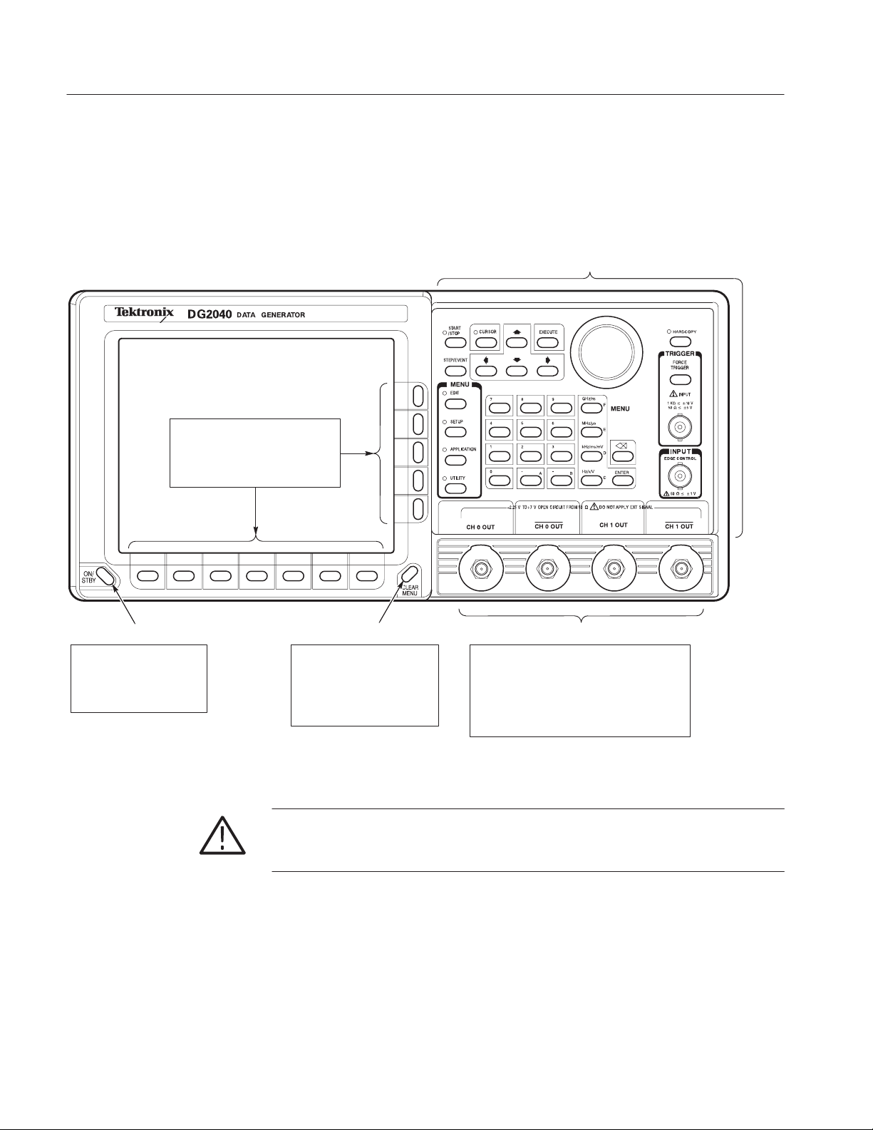
Figure 2-1 Shows the locations of the front panel controls and connectors.
Bottom and side
bezel buttons
The main use of the bottom buttons is
to call up sub menus, and the side
buttons are used to execute more
detailed operations within the sub
menus.
See Figure 2-1 on page 2Ć3
1.1 Gbps
ON/STBY Button CLEAR MENU Button
This button is used as the
power switch in normal
operation. The PRINCIPAL
POWER SWITCH on the rear
panel must be on.
Cancels the current operation
and closes side and submenus.
The display can be returned to
the top level by repeatedly
pressing on the CLEAR MENU
button.
Figure 2Ć1: Front panel controls
CAUTION. If external voltages are applied to the data output connectors, be sure
to set the high-impedance control correctly. Signal collisions may result in
output currents or voltages in excess of the rated values.
Output Connectors
The CH 0 to CH 1 SMA connectors output pattern
data with variable output level in the range
-1.125 V to +3.50 V into 50 W. The delay times
for each channel can be varied from -1.0 ns to
+1.0 ns. If you use only one output connector for
each channel, you must terminate the other
connector using an SMA termination.
2Ć2
DG2040 Data Generator
Page 33

Operating Basics
START/STOP Button
Starts or stops pattern data output. When automatic pattern data update is not used, the pattern data is updated before output is started.
The indicator lights in the output state. It will flash when there is a discrepancy between the output data and the displayed data due to pattern data not being updated.
When automatic pattern data update is specified, the indicator flashes rapidly during data update. It flashes slowly when automatic update is not performed and data
update is required.
Refer to Update on page 3Ć76 for update mode.
CURSOR Button Arrow Buttons EXECUTE Button GeneralĆpurpose knob
Activates or switches
the cursor. The LED
indicates that the
generalĆpurpose knob
will move the cursor.
The arrow buttons move the
cursor. They are also used for
special functions that are
described on the screen when
enabled.
STEP/EVENT Button
Advances the
pattern data by 1
step when in step
mode.
Generates an event
pulse when the run
mode is enhanced
mode.
MENU Buttons
These buttons are
the main menu
buttons. When
pressed, the menu
is displayed and the
corresponding LED
is on.
Numeric Keys, Units Buttons
The numeric keys enter values in numeric or character
input mode. The characters A to F are allocated to keys for
hexadecimal input. Instructions are displayed when used
for other operations.
When a units button appropriate for the input item is
pressed, the input value and unit are confirmed.
Executes the edit
operation set up with the
EDIT menu. Confirms
selection operations in
selection screens.
GHz/ns
ENTER Key
Confirms numeric and
character input.
Delete Key
Deletes previously input digits
during numeric input. Deletes the
character directly in front of the
cursor during character input.
Controls several functions
and adjusts numeric values.
The knob icon displayed on
the screen indicates that this
knob controls the item.
HARD COPY Button
Makes a hard copy of the
current screen. The LED
flashes while in progress.
FORCE TRIGGER Button
Generates a trigger event.
TRIGGER INPUT
BNC connector accepts an
external trigger signal.
EDGE CONTROL
BNCĂconnector accepts an external
signal to move the edge position on
CH0 data output.
Figure 2Ć1 : Front panel controls (cont.)
CAUTION. Only apply signals within the stipulated ranges to the TRIGGER
INPUT connector. Signals that exceed those ranges can damage the instrument.
DG2040 Data Generator
2Ć3
Page 34
Operating Basics
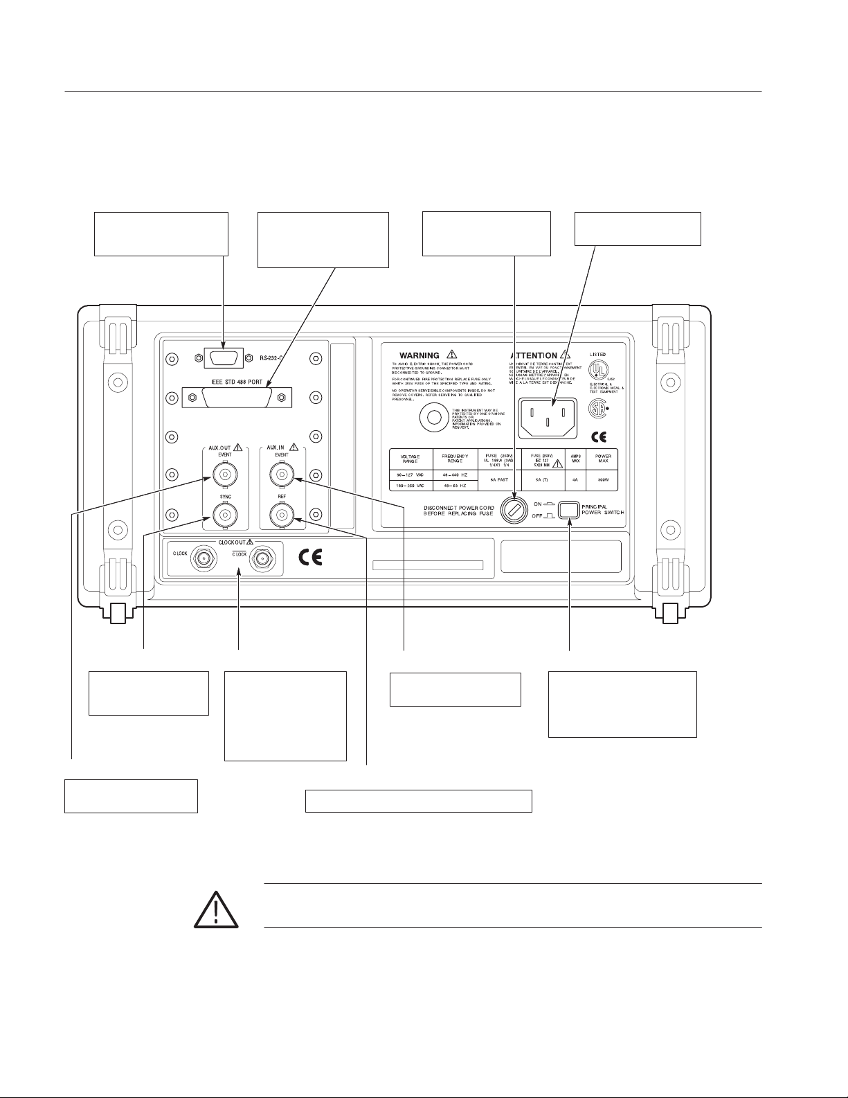
Rear Panel
RSĆ232 Connector
The RSĆ232 connector is
used for remote computer
control over a serial interface.
Figure 2-2 shows the rear panel signal and power connectors.
IEEE STD 488 Connector
This is a GPIB connector for
remote computer control
through an IEEE 488
standard parallel interface.
DIE IN DIESEM GERAT ENTSTEHENDE
RONTGENSTRAHLUNG IST AUSREICHEND ABGESCHIRMT
BESCHLEUNIGUNGSSPANNUNGKLEINER ALS
Power Supply Fuse Holder
The same 6A fastĆblow fuse
is used for both 115V and
230V systems.
20 KV
Power Connector
Connect the provided power
cable to this connector.
SYNC OUT Connector
BNC connector provides a
TTL level synchronization
output signal.
CLOCK OUT Connector
SMA connector provides
an internal clock output
signal. If you use only one
CLOCK OUT connector,
you must terminate the
other connector using an
SMA termination.
EVENT OUT Connector
BNC connector provides a
TTL level event output signal.
Figure 2Ć2: Rear panel connectors
2Ć4
EVENT IN Connector
BNC Connector accepts a
TTL level event input signal.
PRINCIPAL POWER SWITCH
This switch applies power to the
standby circuit. In addition to this
switch being on, the front panel
ON/STBY switch must also be
turned on.
EXT REF IN Connector
BNC connector accepts a external reference signal.
CAUTION. Voltages in excess of the stipulated range can damage the instrument.
Apply signals within the stipulated range to the AUX INPUT connector.
DG2040 Data Generator
Page 35

Operating Basics
Floppy Disk Drive
Figure 2-3 shows the floppy disk drive controls and indicators. The floppy disk
drive is located on the right side of the DG2040 Data Generator chassis. Use the
floppy disk drive to save and recall instrument patterns and for setting data.
CAUTION. Data corruption on the floppy disk may occur if the eject button is
pressed while the DG2040 Data Generator is writing to the floppy disk.
LED indicator Eject button
When the disk drive is in operation, the
LED indicator is on.
Remove a floppy disk by pressing the
eject button.
Figure 2Ć3: Floppy disk drive
DG2040 Data Generator
2Ć5
Page 36

Operating Basics
Display Elements
Figure 2-4 shows the display elements, including bottom and side menus, work
area, status lines, and so on. Also shown are a pop-up menu and message box.
Table 2-1 describes each element in detail.
1 2
6
5
3
Figure 2Ć4: Display elements
2Ć6
4
7
8
DG2040 Data Generator
Page 37

Table 2Ć1: DG2040 display elements
Reference
number
1 Status area
Label Description Page
Displays the current status of the instrument. This status
line is always displayed. The status line displays the
following two items:
MODE: Displays the run mode in which pattern
data will be output.
Operating Basics
3Ć74
UPDATE: Displays the update method for pattern
data output when data is updated.
In addition, there is also a disk icon that indicates if a
floppy disk is inserted in the disk drive. A clock icon may
also be displayed at the left end of the status line. When
this icon is displayed, the instrument is busy with internal
processing and cannot accept other inputs.
2 Date and Time
display area
3 Side menu Related side menu items are displayed here when a
4 Bottom menu When one of the buttons in the menu section is pressed,
5 Button function
description
area
6 Message for
display area
7 PopĆup for
message box
8 PopĆup menu The instrument sometimes displays a popĆup menu
The date and time display can be turned on or off using
the display function of the UTILITY menu.
bottom menu item is selected. The topmost entry in the
side menu displays either a label representing the side
menu or the operation name for the confirmed item.
the corresponding bottom menu is displayed. When a
bottom menu item is selected the corresponding side
menu is displayed. Selecting the same bottom menu
item again closes the side menu.
Displays descriptions of the functions of the frontĆpanel
buttons.
Displays messages regarding the current processing
state. This area can be also used by remote commands
to display user messages.
When required, the instrument temporarily displays a
window at the center of the screen to display a warning
or question for the user.
when a bottom menu or side menu item is selected.
Enter a numeric value or select an item using either the
generalĆpurpose knob or the frontĆpanel buttons.
3Ć76
3Ć89
2Ć15
2Ć15
2Ć2
and
2Ć3
2Ć6
2Ć25
2Ć6
DG2040 Data Generator
2Ć7
Page 38

Operating Basics
Theory of Operation
This section presents an overview of the DG2040 Data Generator hardware, data
structures, and operating modes to allow you to take full advantage of the
DG2040 Data Generator.
Reference
Input
Trigger Input
Block Diagram
Edge Control Input
Clock Unit
PLL
Figure 2-5 shows the main hardware blocks that make up the instrument. This
section describes these hardware blocks to provide the background knowledge
necessary to use the instrument effectively.
Event Input
Clock
Bus
Pattern Generation Unit
Pattern
Control
Circuit
CPU Unit
CPU
Pattern Memory
Sequence Memory
ROM
RAM
GPIB
Output Channels
RSĆ232ĆC
GPIB
RSĆ232ĆC
Data Output
(CH0 and CH1,
Complementary)
Clock Output
(Complementary)
Event Output
Sync Output
Front Panel
Figure 2Ć5: Hardware block diagram
2Ć8
Display
Floppy Disk Drive
DG2040 Data Generator
Page 39

Operating Basics
CPU Unit
Pattern Generation Unit
The CPU unit controls the instrument and includes read only memory (ROM),
random access memory (RAM), and an input/output (I/O) interface.
The ROM memory holds the program code that implements all the supported
functions. The ROM contents are loaded at the factory.
The RAM memory holds a variety of information required by the CPU. The
contents of RAM change according to the instrument’s operating state. The
contents of RAM are retained by a built-in battery even when the instrument is
turned off. The main instrument settings will still be in effect the next time the
instrument is turned on. The pattern data memory and the sequence data
memory, which are described later as a conceptual data model, are actually stored
in one section of this RAM.
External interfaces include GPIB and RS-232 interfaces for remote control, a
floppy disk drive controller, and a user interface consisting of the display and the
front panel.
The pattern generation unit generates digital pattern signals based on the pattern
data and sequence data specified by the user. This unit includes a pattern control
circuit, pattern memory, and sequence memory.
Pattern memory and sequence memory are high-speed memories that hold the
pattern data and sequence data, which are described later in this section. These
memories supply pattern data to the pattern control circuit.
Clock Unit
Output Channels
Display and Front Panel
The clock unit provides the clock signals that generate the data patterns and
detects and synchronizes external trigger signals.
The data generator uses the phase-lock-loop (PLL) circuit when generating the
clock signals. This provides an output with excellent frequency precision.
The output channels provide variable output levels and digital signals to the
device under test.
The output channels level-convert the pattern signals from the pattern generation
unit to output signals appropriate for the device under test. They also handle fine
adjustment of specific bit timing.
The user interface consists of the display and front panel.
The display is a 16-level monochrome 640 × 480 pixel CRT. The front panel
consists of menu buttons, numeric keys, bezel buttons, a general-purpose knob
for changing numeric values and item selection, and several signal output
connectors.
DG2040 Data Generator
2Ć9
Page 40

Operating Basics
Data Structure Overview
To make full and efficient use of the DG2040 Data Generator, you need to
understand the data structures of the DG2040 Data Generator. This section
presents an overview of the pattern data, setup data, and sequence data. Figure
2-6 shows the data structures that are described in the following sections. Table
2-2 lists the data structure related technical terms that appear frequently in the
operating procedure descriptions.
Block Delimiter
BlockBlockBlockBlock
Group
Group
Allocation
D1
D0
Pattern Data
Output Channel
Allocation
Output
Channels
Figure 2Ć6: Data structures
Table 2Ć2: Data structure terms
Term Meaning
Pattern data Basic data for patterns, consisting of 2Ćbit words
Memory size The number of pattern data words (360 words to 256 K words)
Group allocation Definitions of pattern data bit combinations
Block delimiter Delimiter that defines pattern data start and stop points
Block division Pattern data division by block delimiters
Output channel allocation Definition of the corresponding relationship between pattern data
and output bits
2Ć10
Pattern Data
Setup data Settings for the above items
Sequence data Pattern output sequence program
Pattern data is the basic data that defines the digital signals to be output. The
pattern data is a collection of 2-bit words. The total number of words is called
the memory size. The memory size can be any value from a minimum of
360 words to a maximum of 256 K words (262,144).
DG2040 Data Generator
Page 41

Operating Basics
Pattern data that has been transferred to the pattern memory in the pattern
generation unit hardware can be output as digital signals. Pattern memory
consists of 2-bit words, with the 2 bits in a one-to-one correspondence with the 2
output channels. The definition of the relationship between pattern data bits and
pattern memory bits is called output channel allocation.
The pattern data to pattern memory transfer operation is performed automatically
each time the data is modified, or you can manually cause the transfer to occur.
This is called the data update mode, and it can be selected by user.
Setup Data
Groups
Blocks
There are numerous settings that define data structures and relationships between
data items and that specify output channel states and other parameters. These
settings are collectively referred to as the setup data. Since this data is associated
with the pattern data, it is handled together with the pattern data in operations,
such as saving instrument settings and data to a floppy disk.
The setup data includes a wide range of settings, including output voltage levels,
delay, and clock frequency settings in addition to the definitions described here.
Although each bit in the pattern data can be defined independently, it is easier to
edit and display data if multiple bits are collected and handled as a single group.
Any set of bits can be assigned as a group.
Pattern data can be divided into blocks. A block is a user-specified range of
pattern data identified with a unique label. Blocks are divided by setting
delimiters called block delimiters. Block delimiters are set in word units.
Sequences, which are described later, control data output in block units.
DG2040 Data Generator
2Ć11
Page 42

Operating Basics
Sequence Data
The sequence data is a program that specifies the order in which the pattern data
is output. The sequence data is used to set up operations, such as repeatedly
putting out blocks of pattern data for a specified number of times and jumping to
a specified block when an external event occurs. Sequences allow long patterns
to be set up without preparing large quantities of data.
Sequences can include subsequences so that you can make complex sequence
programming easier. Sequence data is transferred to the pattern generation unit
sequence memory, and controls the operation of the pattern control circuit.
When you use the run mode you can select whether all the sequence data is valid
or whether enhanced mode settings, such as event jumps in the sequence, are
ignored.
Operating Modes Overview
Run Modes
In the run modes, pattern output is controlled by the pattern generation units
pattern control circuit. The DG2040 Data Generator supports four run modes:
repeat, single, step, and enhanced. These run modes are specified with the
SETUP → Run Mode menu. Table 2-3 provides functional information for each
mode.
Table 2Ć3: Run modes
Run mode Function
Repeat Repeats the pattern data from the first to last data point indefinitely.
If a sequence is defined, it repeats the output according to that
sequence.
Single Outputs the pattern data once from the first to last data point in point
order. If a sequence is defined, outputs the pattern once according to
that sequence.
Step Operates identically to repeat mode, except that just one data point
is output each time the STEP/EVENT button is pressed.
Enhanced Same as Repeat with the addition that event jumps and trigger waits
are also effective.
NOTE. The Repeat, Single, and Step modes ignore the event jump and trigger
wait settings.
2Ć12
DG2040 Data Generator
Page 43

Operating Basics
Update Modes
When pattern data or sequence data is created or edited or the output channel
allocations are changed, the pattern that is actually output will not be updated
until the new settings are transferred to the pattern generation unit.
There are two update methods: auto and manual. The update modes are set up
with the Update item in the SETUP ! Run Mode menu. Table 2-4 provides
functional information for both modes.
Table 2Ć4: Update modes
Update mode Function
Auto Changes are reflected in the hardware as soon as they are entered.
Manual Changes are reflected in the hardware when specified by you.
NOTE. The response to edit operations while in Auto mode may be slow when
there is a large amount of data being edited. In such cases, it is more efficient to
perform a number of edit operations and then update the output data in manual
mode.
Basic Menu Operations
Menu System
This section describes the DG2040 Data Generator menu system and numeric
input methods.
The menu system is used for instrument settings, instrument operation, and
selection of the pattern data output parameter. Pressing one of the menu buttons
at the center of the front panel displays one of the menus that forms the basis of
DG2040 Data Generator operation. There are four menu buttons, EDIT, SETUP,
APPLICATION, and UTILITY, as shown in Figure 2-7.
The menu items displayed on the screen are selected by pressing the corresponding bottom or side bezel button. The bezel buttons consist of seven bottom
buttons and five side buttons, as shown in Figure 2-7.
DG2040 Data Generator
2Ć13
Page 44

Operating Basics
1.1 Gbps
Side Buttons
Bottom Buttons
Menu
Buttons
Figure 2Ć7: Menu and bezel buttons
When the target menu item is selected, the selection items and numeric input
entries controlled by that menu are displayed. Items can be selected or numeric
values changed using the numeric keys and the general-purpose knob.
Selecting a menu item causes one of the following operations:
H Invokes a lower level menu
H Selects an item:
H The selected item changes each time a bezel button is pressed.
2Ć14
Menu Notation
H A list is displayed and an item is selected from that list.
H Enables a numeric input
H Executes the function associated with the menu item as soon as the menu
item is selected.
The following notation is used in this manual to show the order to push
instrument buttons:
Front panel menu button ! Bottom menu button ! [Side menu button or
pop-up menu item]
The menu path starts with a front panel menu button, followed by an arrow (!),
and then a bottom menu. The item in parenthesis may be repeated more than
DG2040 Data Generator
Page 45
Operating Basics
once, as needed. For example, SETUP ! Output Condition ! Control
Condition is executed as follows:
1. Press the SETUP button on the front panel.
2. Press the Output Condition bottom button.
3. Press the Control Condition side button.
Menu Item Display
Starting with each main menu, the instrument displays bottom, side, and
submenu items according to fixed rules.
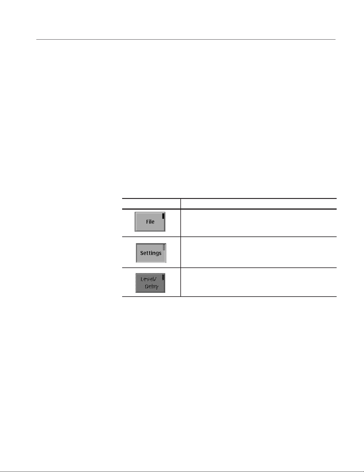
Bottom Menu. The bottom menu changes according to whether items are selected
or not, and whether an item is valid or not, as shown in Table 2-5.
Table 2Ć5: Bottom menu elements
Menu item Description
Menu item in the unselected state. The small box in the upper right
corner is black.
Menu item in the selected state. The small box in the upper right
corner is white.
Menu item that cannot be selected, since it is invalid in the current
state.
DG2040 Data Generator
Side and Submenus. The menu items that are manipulated with the side buttons,
can be classified according to the manipulations they support. These menu items
can be differentiated visually as shown in Table 2-6.
2Ć15
Page 46
Operating Basics
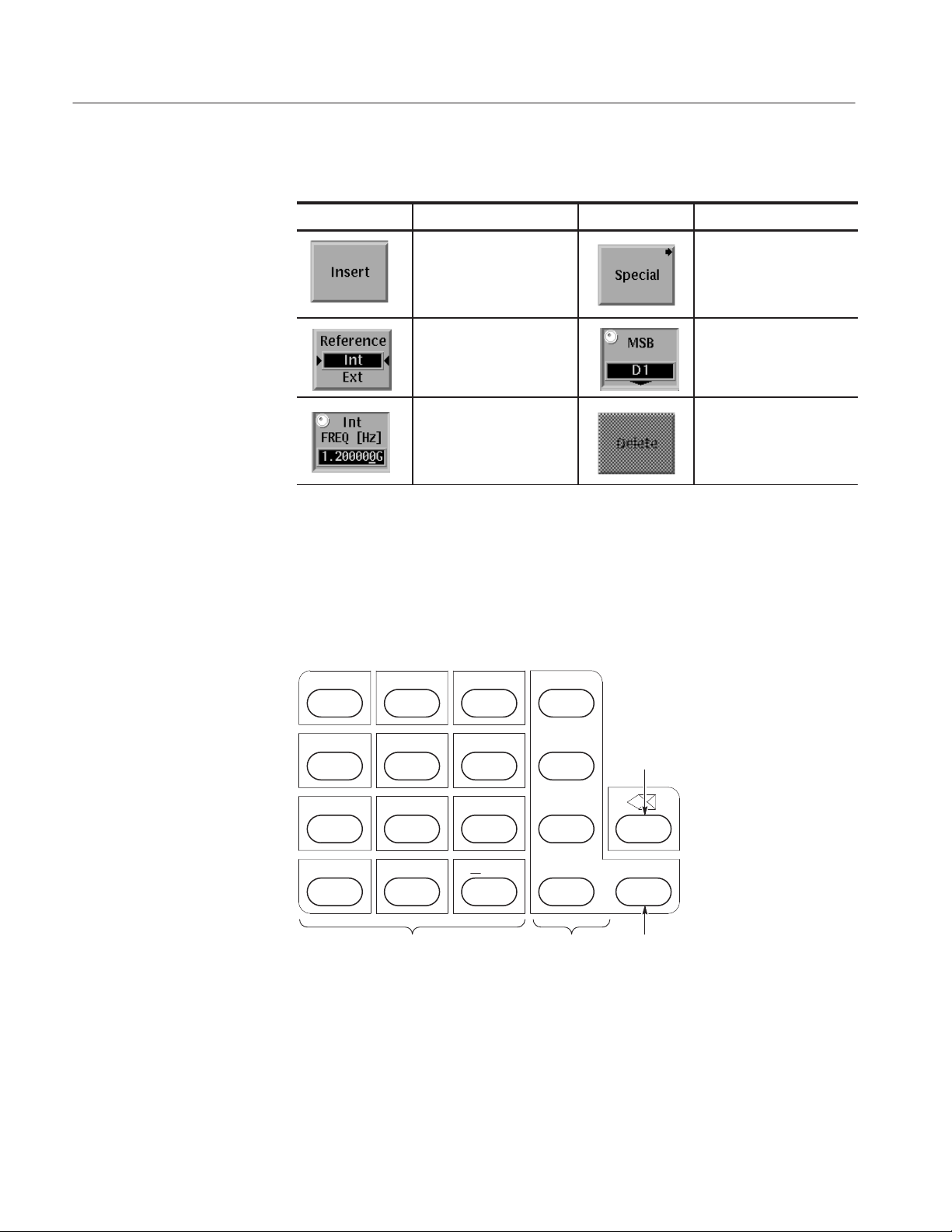
Table 2Ć6: Side and submenu elements
Menu Item Description Menu item Description
Menu items that execute a
function immediately
Menu items that call up
submenus
Numeric Input
Menu items that switch
between on and off each
time the side button is
pressed.
Menu items that allow
numeric values to be set
using the numeric keys or
Menu items that allow
selections to be made
with the generalĆpurpose
knob
Menu items that cannot
be used in the current
instrument state
the generalĆpurpose knob
Enter numeric values by using the front-panel keypad or the general-purpose
knob. This section describes these numeric input methods.
FrontĆPanel Keypad. The numeric keys, the units buttons, the delete key and the
ENTER key are used for entering numeric values. See Figure 2-8.
987
5
64
GHz/ns
MHz/ms
F
Delete
E
Key
2Ć16
1
0
.A
32
B
Numeric
Keys
Figure 2Ć8: DG2040 frontĆpanel keypad
kHz/ms/mV
D
Hz/s/V ENTER
C
Units
ENTER
Buttons
Key
DG2040 Data Generator
Page 47
Operating Basics
p
Use the following procedure to input numeric values with the numeric keys,
ENTER key, and units buttons on the front panel.
1. Press the button for the menu item to be changed.
2. Input the value using the numeric keys.
3. Press a units button or the ENTER key.
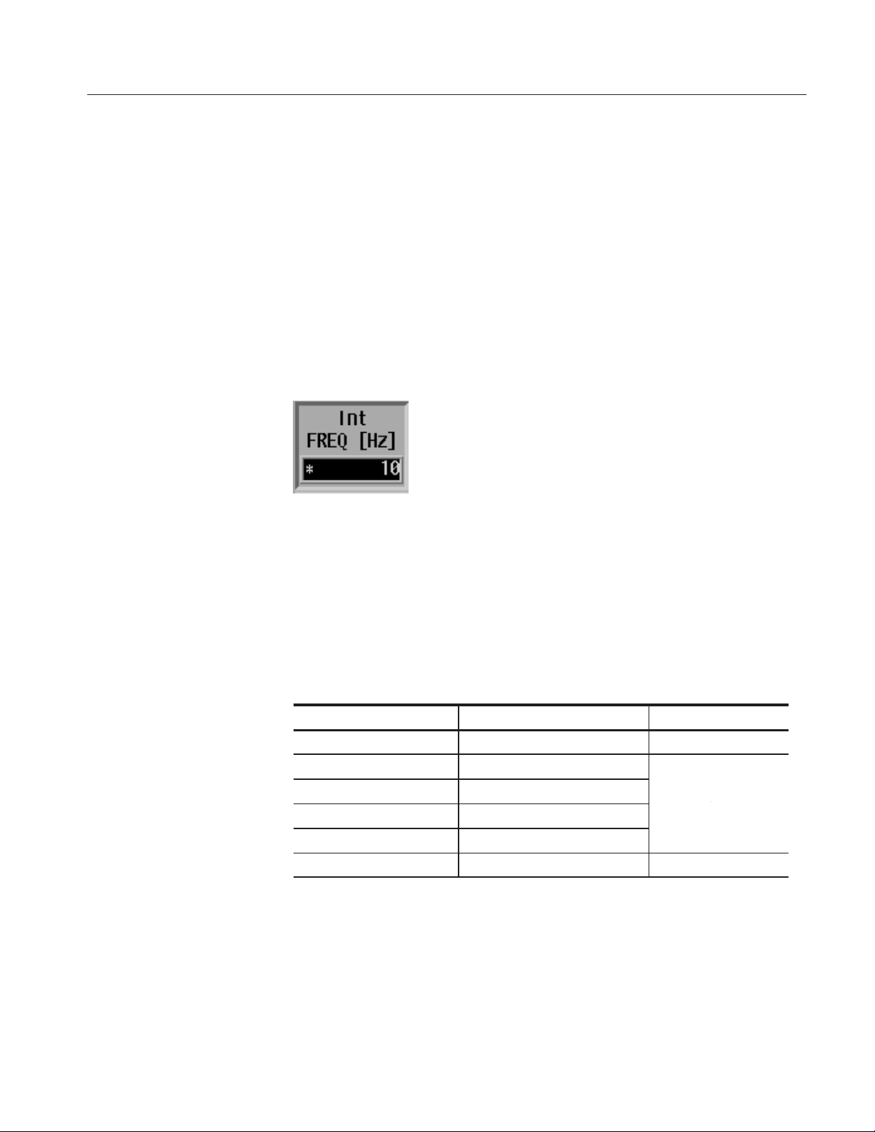
Figure 2-9 shows a menu display during numeric input. The asterisk to the left of
the menu items indicates that you are entering a value in that field. Press the
front panel ENTER key to confirm an entered value and to remove the asterisk
from the menu item field.
Figure 2Ć9: Numeric entry in a menu item field
Numeric Input Example. Table 2-7 shows how to change the clock frequency to
12.3 Hz when the value, before entering the input state, was 100.0 Hz. Press the
1, 2, ., 3, and ENTER keys in that order. The numeric input box changes as
shown in Table 2-7.
Table 2Ć7: Numeric input example
Press keys in this order Numeric input window display State of the value
100 Hz PreĆnumeric input
1 *1
2 *12
. * 12.
3 * 12.3
ENTER 12.30000 Hz Value confirmed
Numeric input
in progress
Press a units button after a value has been entered to confirm both the value and
the unit in a single operation. Pressing a units button before entering the input
state changes only the unit without changing the value.
DG2040 Data Generator
2Ć17
Page 48
Operating Basics
Failure to press the ENTER key or a units button after entering a value, prior to
switching menu items, will cause the entered value to be discarded. The value
returns to the previous value.
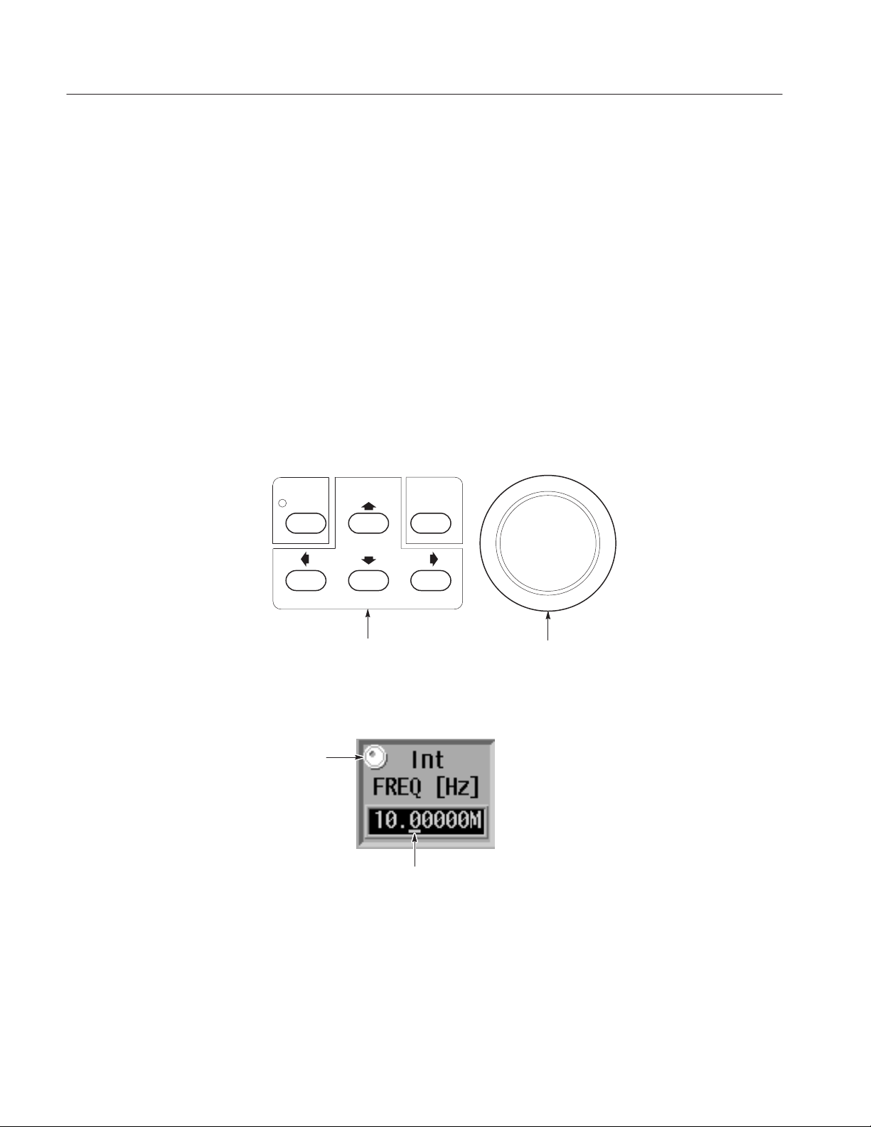
Setting Values with the GeneralĆPurpose Knob. The general-purpose knob and the
left and right arrow buttons can be used to set values in numeric input boxes.
The knob icon is displayed close to the box to show that you can use the
general-purpose knob to enter values. The general-purpose knob is used to
increase or decrease the value of the digit indicated by the underscore. Rotating
the knob to the left decreases the value and rotating it to the right increases the
value.
Figures 2-10 shows the arrow keys and the general-purpose knob.
Figure 2-11 shows a menu element that can use the general-purpose knob to
enter numeric values.
CURSOR EXECUTE
Arrow Buttons generalĆpurpose knob
Figure 2Ć10: GeneralĆpurpose knob and arrow buttons
Knob Icon
Underscore
2Ć18
Figure 2Ć11: Menu element knob icon and underscore
You do not need to use the front panel ENTER key to confirm a value when
using the general-purpose knob to change a value. The input value is confirmed
automatically without pressing the ENTER key.
DG2040 Data Generator
Page 49

Operating Basics
Follow the procedure below to change a value with the general-purpose knob.
1. Press the button for the menu item to be changed.
2. Use the left and right arrow buttons to move the underscore line to the digit
to be modified.
The front panel arrow buttons control the amount of change that can be
achieved with the general-purpose knob. Pressing the a button moves the
underscore one digit to the left and thus multiplies the effect of turning the
general-purpose knob by ten. Inversely, pressing the ' button moves the
underscore one digit to the right and reduces the effect of turning the
general-purpose knob by a factor of ten.
3. Change the value by turning the general-purpose knob.
Pattern Data Display
Format
You can display pattern data in one of four formats: timing display, table display,
binary display, and numeric display. Use the EDIT ! Settings item to select the
display format.
You get the same output results from whichever display format you select. Use
these different formats according to your needs. These display formats are
discussed below .
Timing Display Format. The Timing display format shows the waveform patterns
for the data graphically with the time axis in the horizontal direction. The Timing
display shows the data so that data transitions and the relationships between bits
can be easily seen. Refer to Figure 2-12.
Figure 2Ć12: Timing display format
DG2040 Data Generator
2Ć19
Page 50

Operating Basics
Table Display Format. The Table display format shows the data for each clock as
numeric values for each group. Refer to Figure 2-13.
Figure 2Ć13: Table display format
Binary Display Format. The Binary display format shows the data bit states for
each clock as 0 or 1. This is the basic display for digital signals and is an
appropriate format for handling data in bit units. If no groups are defined, data
can only be displayed in binary format. Refer to Figure 2-14.
Figure 2Ć14: Binary display format
2Ć20
DG2040 Data Generator
Page 51
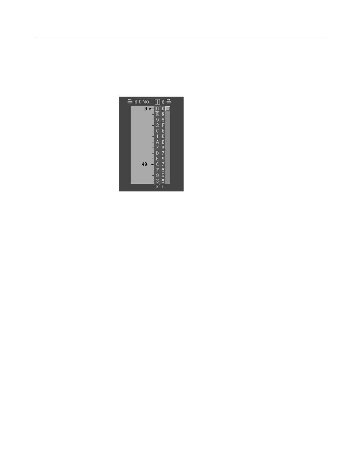
Operating Basics
Numeric Display Format. The Numeric display format shows the data of specified
bit width for binary or hexadecimal radix values. When using the numeric
display format, parallel data can be displayed as serial data. Refer to Figure 2-15.
Edit Operations
Figure 2Ć15: Numeric display format
The different editing operations are selected from the EDIT ! Execute Action
menu. Press the front panel EXECUTE button to execute the selected operation.
Editing can be accomplished quickly by using the general-purpose knob and the
CURSOR button to move the cursor. Press the EXECUTE button to complete
the process. Figure 2-16 shows the procedure used to select the Invert data
editing operation and invert data bits at three locations.
DG2040 Data Generator
2Ć21
Page 52

Operating Basics
1
Select Invert data.
Execute Action menu
Before
execution
Move the cursor to the numbered positions.
At each position, press the EXECUTE button
to take the selected action.
2
34
After
execution
Pattern data
Figure 2Ć16: Pattern data editing procedure
Parallel/Serial Editing. The Numeric display format allows you to edit the data of
every specified bit width in a selected data bit. You can select two to 32 bits and
edit in BIN (binary) or HEX (hexadecimal) format. Figure 2-17 show an
example of displaying and editing in 4 bit width in HEX format.
5E
63C7C
.....
Figure 2Ć17: Serial/Parallel editing mechanism
2Ć22
DG2040 Data Generator
Page 53

Operating Basics
To edit serial data as parallel data, select bit width in the Bit Width pop-up menu
brought up by selecting Settings ! Set numeric view format, select Settings
! Set view type of numeric, and then select Execute Action ! Numeric
Input. Press the numeric key after you have pressed EXECUTE key on the
front panel.
This editing function allows you to convert parallel data to serial data.
Area and Point Cursors
Cursor Window Width Window Cursor Window Value
Knob Icon
When editing pattern data, there are two types of cursors used for indicating the
data that will be the object of the edit operation. The type of cursor used depends
on whether a particular point in the data must be indicated, or an area of data
must be indicated.
Each type of cursor has a different form. They are called the area cursor and the
point cursor. Figure 2-18 shows these cursors.
Point Cursor
Area Cursor
Scope
Figure 2Ć18: Area and Point cursors
The area cursor is used to select a range of signal data, such as during a copy
operation. In this operation, the data in the area specified by the area cursor is
copied to the edit buffer memory. The paste operation is an example where the
point cursor is used. In this operation, data that was previously loaded into the
edit buffer memory is copied into pattern memory at the point specified by the
point cursor.
The area cursors area is determined by a combination of an area origin (as
defined by a data group and a sample point position), the number of points
(which corresponds to the width of the area) and the scope (which corresponds to
the height of the area). The origin data group is set with the up and down arrow
DG2040 Data Generator
Width Window Value
2Ć23
Page 54

Operating Basics
buttons. The area cursor origin sample point is displayed in the Cursor window
at the upper left of the screen in the same way as the point cursor is displayed. It
can be manipulated in the same way as the point cursor.
The width of the area cursor is displayed in the Width window. It can be set with
the general-purpose knob or numeric keys when the knob icon has been moved
to the Width window using the CURSOR button. Use the EDIT ! Execute
Action ! Set Scope item to set the area cursor height.
The position of the point cursor is determined by a data group and a sample
point. The data group is set with the vertical arrow buttons. The sample point
position is displayed in the Cursor window at the upper left of the screen. It can
be set with the general-purpose knob or the numeric keys when the knob icon
has been moved to the Cursor window with the front panel CURSOR button.
Text Input
Text input is required to enter the names for data groups, data blocks, floppy disk
files, and other items. When such input is required, the instrument automatically
brings up the dialog box shown in Figure 2-19.
Figure 2Ć19: Text input menu
The text input menu displays a default string for the item. Use the side menu
Clear String button to erase this default string. Use the arrow buttons or the
general-purpose knob to move the reverse-video cursor to the desired character in
the letter/digit matrix. Press the EXECUTE button to complete the process.
Incorrect input can be erased with the delete key. The position where the
character is inserted is indicated with an underscore. Use the left and right arrow
buttons to change the position of the underscore. Select all the required
characters then press the OK button on the side menu to complete the process.
Press Cancel on the side menu to cancel text input and return to the previous
menu.
2Ć24
DG2040 Data Generator
Page 55

Operating Basics
PopĆup Message Box
The instrument displays a message box that prompts you to confirm operations
that would be difficult to recover. Figure 2-20 shows the file deletion confirmation message box. Press the side menu OK button to execute the operation
displayed in the box. Press Cancel to cancel the operation and return to the state
prior to selecting the current menu.
Figure 2Ć20: PopĆup message box
DG2040 Data Generator
2Ć25
Page 56

Operating Basics
Tutorials
This manual provides simple tutorials to learn the basic procedures for pattern
signal creation and output. Following are the five tutorials that will be given:
H Creating a Pattern and Storing into a File on page 2-27
H Loading and Editing a Pattern Stored in a File on page 2-30
H Setting up Signal Output on page 2-34
H Creating a Sequence on page 2-37
H Controlling Pattern Edges on page 2-49
Refer to the menu descriptions in the Reference section for detailed explanations
of the menus and functions used in these procedures.
NOTE. These tutorials do not cover all the features and functions of the DG2040
Data Generator. They are intended only to introduce the operations required to
execute the instrument’s basic functions.
Be sure that the DG2040 Data Generator is properly installed. Refer to Installation on page 1-7.
Refer to Power On on page 1-9 for power-on instructions.
The following equipment is required for Tutorials 1 through 5:
H An IBM-formatted 3.5 inch floppy disk (2HD, 1.44 MB)
H A digital storage oscilloscope (a Tektronix TDS700-series oscilloscope or
equivalent)
H A BNC cable
H Two SMA terminations
H Two SMA cables
H Two SMA female-to-BNC male adapters
Each operating procedure is presented in table format beginning with step 1 and
progresses through the end of the procedure. Tables, such as the one shown on
page 2-27, list the steps for each procedure task. For these steps, press the
buttons in the order shown in the table, from left to right in each row, from top to
bottom of the table.
2Ć26
If a number is shown in the front-panel button column, enter that value using the
keypad.
DG2040 Data Generator
Page 57

Operating Basics
Use the general-purpose knob to select items from the menu list on pop-up
menus.
Operations such as Operation 6 (below) do not involve pressing the buttons
shown in the row above, but rather are descriptions of operations to be performed. Figure 2-21 shows the buttons used and the menu layout.
FrontĆPanel
Menu button Bottom button PopĆup menu Side button
Operation 1 Operation 2 Operation 3 Operation 4 Operation 5
Operation 6 (For example, set to xx with generalĆpurpose knob.)
Operation 7
button
Tutorial 1: Creating a
Pattern and Storing
the File
Side Menu
Bottom Menu
GeneralĆpurpose knob
Front-Panel Buttons
Menu ButtonsBottom Buttons Side Buttons
Figure 2Ć21: Operating buttons
Tutorial 1 creates the output pattern for an 2-bit binary counter and stores that
pattern onto a 3.5 inch floppy disk.
NOTE. Initialize the instrument’s data and settings before creating new pattern
data.
DG2040 Data Generator
2Ć27
Page 58

Operating Basics
Follow the steps below by pressing the buttons in the order shown in the
following tables (from left to right in each row and from top to bottom) to create
a pattern and then store the file:
1. Clear the data memory.
FrontĆpanel
Menu button Bottom button PopĆup menu Side button
EDIT File New
OK
button
2. Set up the environment by setting the pattern memory length to 1024 points.
Front-panel
Menu button Bottom button PopĆup menu Side button
Settings Set memory
size
OK 1024 *
button
OK
* Use the frontĆpanel keypad to enter numeric values.
ENTER
2Ć28
DG2040 Data Generator
Page 59

Operating Basics
3. Set the data bit positions and bit widths by setting the height (scope) and
width of the data that you are going to edit.
FrontĆpanel
Menu button Bottom button PopĆup menu Side button
Execute
Action
Move the knob icon to the Cursor window in the upper left area of the screen by
pressing the frontĆpanel CURSOR button once or twice.
Move the knob icon to the Width window in the upper left area of the screen by pressing
the frontĆpanel CURSOR button once.
Set scope OK
2 OK
button
0
ENTER
1024
ENTER
Press the down arrow button until the area cursor covers DATA0 to DATA1.
4. Create the binary pattern for a value increasing every 2 clock ticks.
FrontĆpanel
Menu button Bottom button PopĆup menu Side button
Execute
Action
Binary up
counter
OK 2
OK EXECUTE
button
ENTER
The previous steps created the binary pattern shown in Figure 2-22 in
DATA0 to DATA1.
DG2040 Data Generator
2Ć29
Page 60
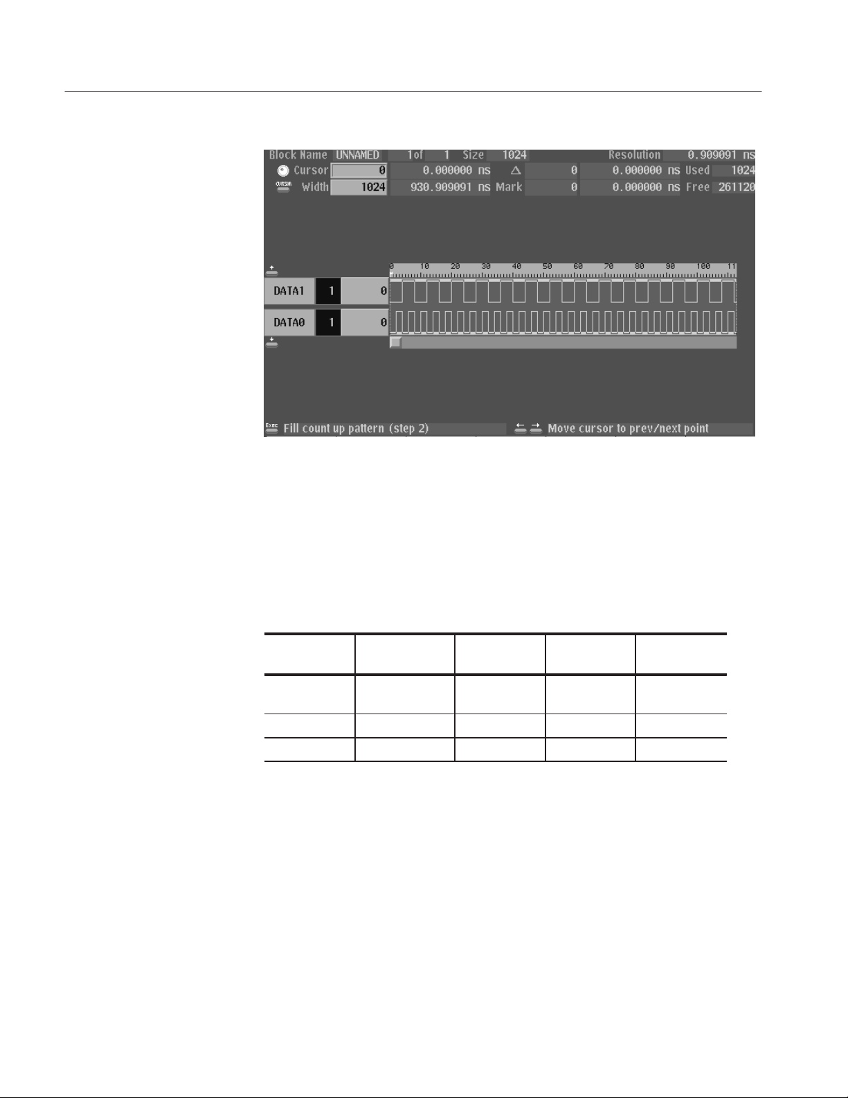
Operating Basics
Figure 2Ć22: Binary pattern creation
Tutorial 2: Loading and
Editing a Pattern
Stored in a File
Follow the steps below to save the created data on the 3.5 inch floppy disk.
5. Insert a blank IBM-formatted 3.5 inch floppy disk in the drive.
6. Name the new file COUNT1.
FrontĆpanel
Menu button Bottom button PopĆup menu Side button
File Save Data &
Setup
Clear String
COUNT1 * OK
* Select each character in the file name using the generalĆpurpose knob and the
up and down arrow buttons. Press the EXECUTE button to insert the character
in the file name.
button
The data in this procedure is saved in the file named COUNT1.PDA.
Tutorial 2 loads a file from a 3.5 inch floppy disk and demonstrates pattern
editing using that data.
Before loading a file from the 3.5 inch floppy disk, initialize the instrument’s
data and settings. This allows you to see the effect of loading the file you
previously saved in Tutorial 1.
2Ć30
DG2040 Data Generator
Page 61
Operating Basics
1. Clear the data definitions.
Front Panel
Menu Button Bottom Button PopĆup Menu Side Button
EDIT File New
OK
Button
Follow the steps below to load the Tutorial 1 file from the 3.5 inch floppy disk:
2. Insert the 3.5 inch floppy disk in the instrument’s 3.5 inch floppy disk drive
and complete the actions in the following table.
Front Panel
Menu Button Bottom Button PopĆup Menu Side Button
EDIT File Load Data &
Setup
Select the file COUNT1.PDA from the file list using the generalĆpurpose knob.
Button
OK
3. Select DATA1 as the area to be edited.
Front Panel
Menu Button Bottom Button PopĆup Menu Side Button
Execute
Action
Move the knob icon to the Cursor window in the upper left area of the screen by
pressing the frontĆpanel CURSOR button once or twice.
Move the knob icon to the Width window in the upper left area of the screen by pressing
the frontĆpanel CURSOR button once.
Press the up and down arrow buttons until the area cursor covers DATA1.
Set scope OK
1 OK
Button
0
ENTER
1024
ENTER
DG2040 Data Generator
4. Complete the following actions to shift the bits in DATA1 exactly one
sample width to the right.
2Ć31
Page 62

Operating Basics
Front Panel
Menu Button Bottom Button PopĆup Menu Side Button
Execute
Action
Shift right
(add zero)
OK EXECUTE
Button
5. Complete the following actions to insert a glitch with a width of 1 sample in
the DATA1 bits.
a. Set DATA1 as the bits that will be the object of the edit.
Front Panel
Menu Button Bottom Button PopĆup Menu Side Button
Execute
Action
Set the block cursor to cover DATA1 using the up and down arrow buttons.
Set scope OK
1 OK
Button
b. Set the glitch width to be 1.
Front Panel
Menu Button Bottom Button PopĆup Menu Side Button
Move the knob icon to the Width window in the upper left area of the screen by pressing
the frontĆpanel CURSOR button once or twice.
Button
1
ENTER
c. Select invert as the edit operation.
Front Panel
Menu Button Bottom Button PopĆup Menu Side Button
Execute
Action
Invert data OK
Button
2Ć32
DG2040 Data Generator
Page 63

Operating Basics
d. Insert two glitches.
Front Panel
Menu Button Bottom Button Popup Menu Side Button
Move the knob icon to the Cursor window in the upper left of the screen by pressing the
front panel CURSOR button once.
Button
35
ENTER
EXECUTE
91
ENTER
EXECUTE
This process inserted glitches at the points for cursor positions 35 and 91.
Figure 2-23 shows the pattern edited in Tutorial 2.
Figure 2Ć23: Pattern edited in Tutorial 2
DG2040 Data Generator
2Ć33
Page 64

Operating Basics
6. Save the edited data on the 3.5 inch floppy disk.
a. Insert a formatted 3.5 inch floppy disk in the drive.
b. Name the new file COUNT2.
Menu Button Bottom Button PopĆup Menu Side Button
File Save Data &
Setup
Clear String
COUNT2 OK
The data in this procedure will be saved in the file COUNT2.PDA.
Front Panel
Button
Tutorial 3: Signal Output
Tutorial 3 sets all the settings required for signal output and actually outputs the
signals.
1. Set the sampling clock frequency to 500 MHz.
FrontĆpanel
Menu button Bottom button PopĆup menu Side button
Clock Reference
(Select Int.)
Int FREQ 500
button
MHz
2. Set the signal generation mode to continuous mode.
FrontĆpanel
Menu button Bottom button PopĆup menu Side button
Run Mode Repeat
button
3. Set the channel CH0 to CH1 output levels to 1 V for the high level and –1 V
for the low level.
2Ć34
DG2040 Data Generator
Page 65

Operating Basics
FrontĆpanel
Menu button Bottom button PopĆup menu Side button
Level Condition
Select channel CH0 by pressing the frontĆpanel up and down arrow buttons.
High 1
Low -1
Set the output levels for channels CH1 in the same manner.
button
ENTER
ENTER
Follow the steps below to set the delay time for each channel.
4. Set the delays for the output channels CH0 to CH1 to 1 ns. Refer to
Figure 2-24 for the output parameter settings example.
Menu button Bottom button PopĆup menu Side button
Timing Condition
Select channel CH0 by pressing the frontĆpanel up and down arrow buttons.
Delay 1
Set the delays for channels CH1 in the same manner.
Delay Time Setting
Output Voltage
Level Settings
Figure 2Ć24: Output parameter settings
FrontĆpanel
button
ENTER
DG2040 Data Generator
Follow the steps below to output the signals and confirm those signals with an
oscilloscope.
5. Connect the DG2040 Data Generator outputs to the oscilloscope.
2Ć35
Page 66
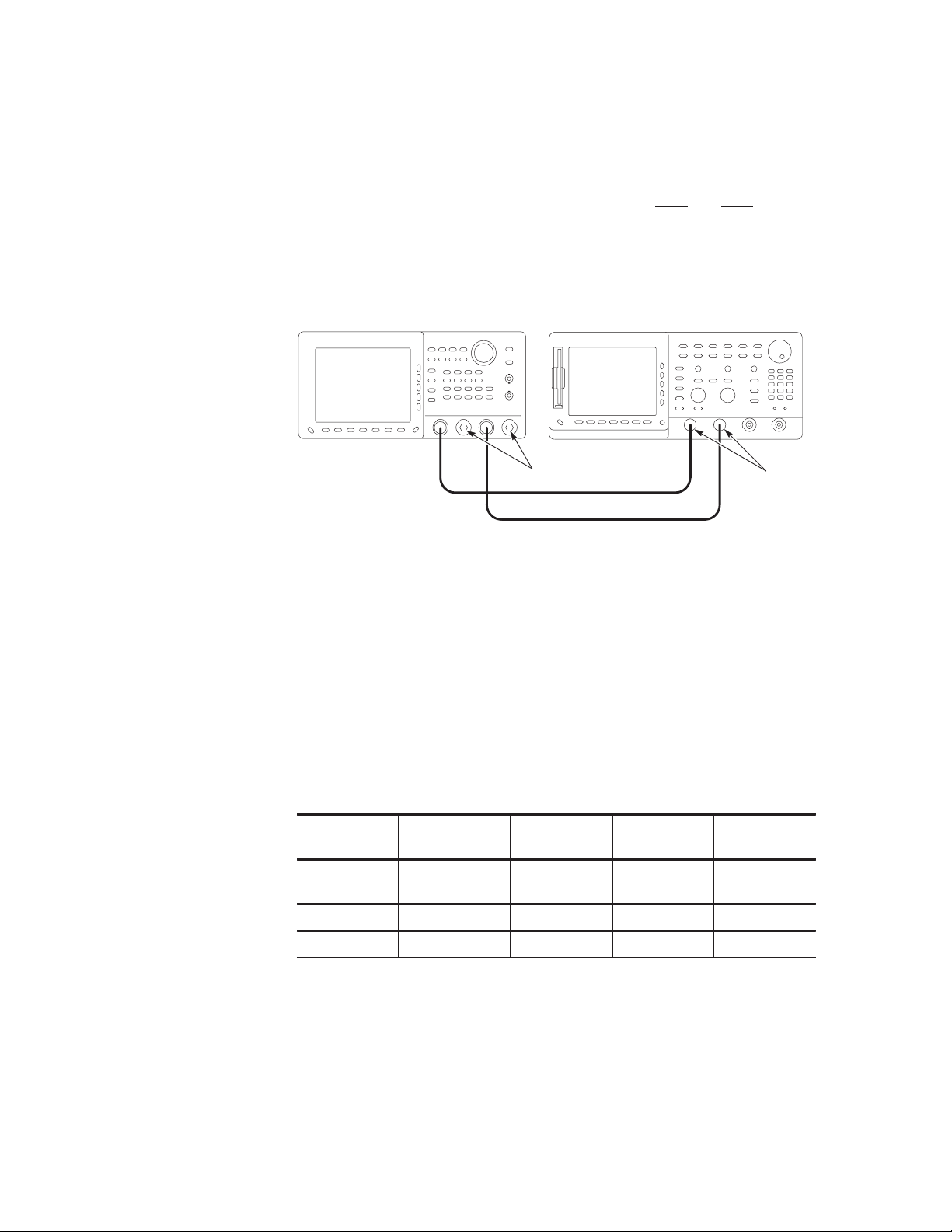
Operating Basics
Connect the CH0 and CH1 on the front-panel to the oscilloscope CH1 and
CH2. This requires two SMA cables and two SMA female-to-BNC male
adapters. Connect two SMA terminations to the CH0
and CH1 outputs on
the DG2040 Data Generator front panel. Refer to Figure 2-25.
DG2040 Data Generator Oscilloscope
CH0
CH1
SMA termination
SMA Cable
CH1
CH2
SMA
femaleĆtoĆBNC
male adapter
Figure 2Ć25: DG2040 Data Generator and oscilloscope connection
6. Press the START/STOP button on the front-panel.
7. Set up the oscilloscope appropriately and observe the pattern signals on the
oscilloscope screen.
8. Save the state of the settings on the 3.5 inch floppy disk.
a. Insert an IBM-formatted 3.5 inch floppy disk in the drive.
b. Name the new file COUNT3.
FrontĆpanel
Menu button Bottom button PopĆup menu Side button
EDIT File Save Data &
Setup
button
2Ć36
Clear String
COUNT3 OK
The data in this procedure is saved to a file named COUNT3.PDA.
DG2040 Data Generator
Page 67
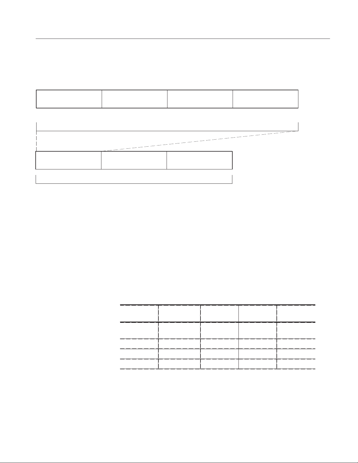
Operating Basics
Tutorial 4: Creating a
Sequence
Block 1 Block 2 Block 3 Block 4
Block 1 repeats 10 times
Defined in subsequence
SUB 1
SUB 1 repeats 2 times
Tutorial 4 creates four 360-bit blocks and assigns the blocks to sequences, as
shown in Figure 2-26.
Block 3 Block 4
Block 3 repeats continually
Figure 2Ć26: Tutorial 4 block sequence
Create the following data patterns for the blocks:
Block 4 repeats 20 times
The sequence repeats Block 3
infinitely. When an event signal
is input, the sequence jumps to
Block 4.
H Block 1: Binary up-counter pattern
H Block 2: Data pattern consisting of all zeros
H Block 3: Binary down-counter pattern
H Block 4: Data pattern consisting of all ones
1. Clear the data group definitions and pattern data.
Menu button Bottom button PopĆup menu Side button
SETUP Group Assign Reset All bits
Assign
OK
EDIT File New
OK
FrontĆpanel
button
DG2040 Data Generator
2Ć37
Page 68

Operating Basics
2. Set the length of pattern memory (the number of samples) to 1440 points.
FrontĆpanel
Menu button Bottom button PopĆup menu Side button
Settings Set memory
size
OK 1440
OK
button
ENTER
3. Set the block cursor position and width. This procedure sets a scope of 2
(DATA0 and DATA1) and a width of 360 samples.
FrontĆpanel
Menu button Bottom button PopĆup menu Side button
Execute
Action
Set scope OK
button
2 OK
Move the knob icon to the Width window in the upper left area of the screen using the
frontĆpanel CURSOR button.
360
ENTER
4. Divide the data between block 1 (point 0 to 359) and block 2 (point 360 to
719). Use BK2 as the name for block 2.
FrontĆpanel
Menu button Bottom button PopĆup menu Side button
Move the knob icon to the Cursor window in the upper left area of the screen by
pressing the frontĆpanel CURSOR button once or twice.
Block Add block
delimiter here
BK2 OK
OK
Clear String
button
360
ENTER
2Ć38
DG2040 Data Generator
Page 69
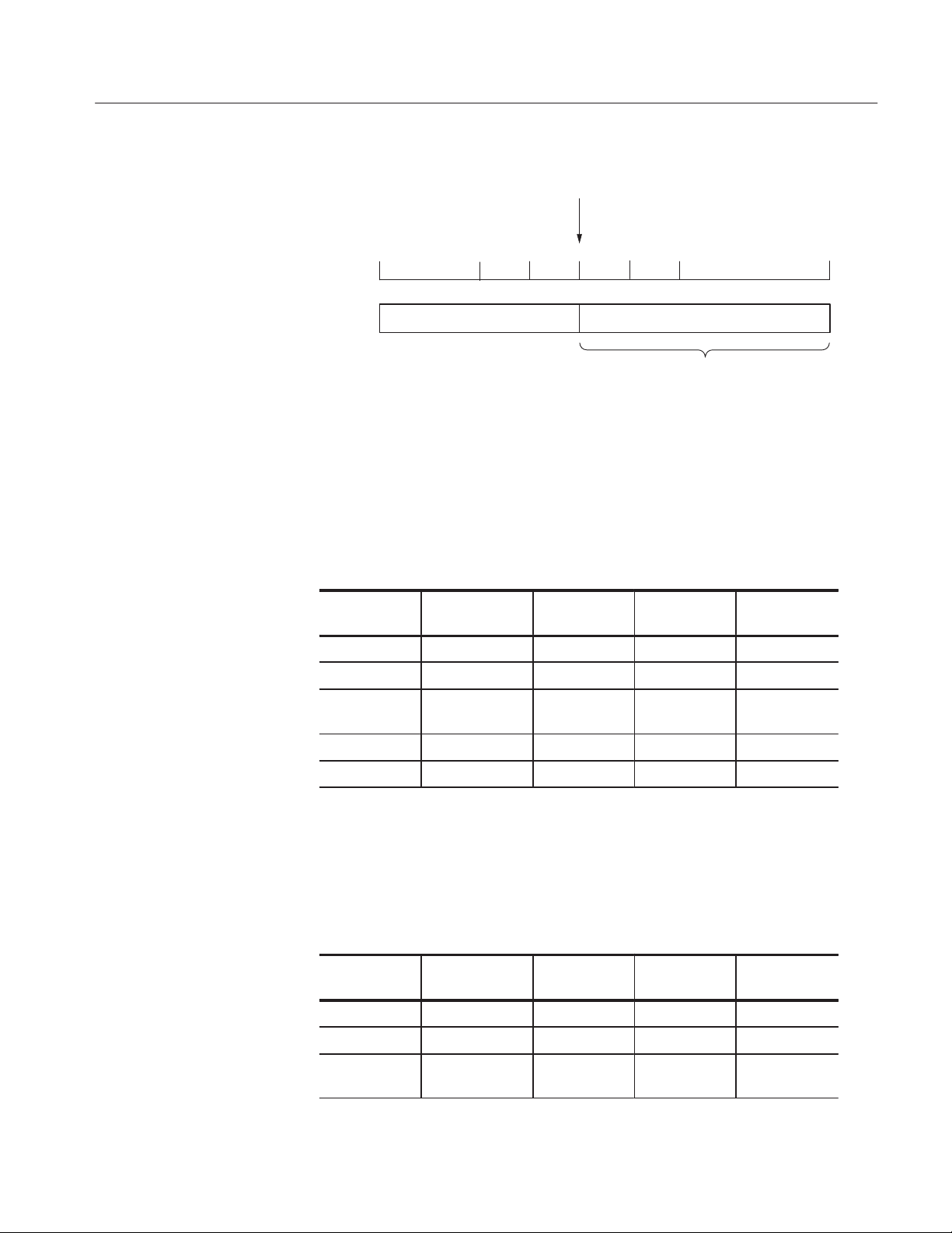
Place a block delimiter here
(to separate the blocks)
Operating Basics
Point No.
. . . . . . . . . . . .
362359 360 361 7190 358
Block 2Block 1
Current Edit Screen
Figure 2Ć27: Block separation
5. Divide the data from point 360 to point 719 between block 2 (360 to 719)
and block 3 (720 to 1079). Use BK3 as the name for block 3. Confirm that
the knob icon appears in the Cursor window in the upper left area of the
screen. If the icon is not in that window, move it there with the front-panel
CURSOR button.
FrontĆpanel
Menu button Bottom button PopĆup menu Side button
button
720
ENTER
Block Add block
delimiter here
BK3 OK
OK
Clear String
6. Divide the data from point 720 to point 1079 between block 3 (720 to 1079)
and block 4 (1080 to 1339). Use BK4 as the name for block 4. Confirm that
the knob icon appears in the Cursor window in the upper left area of the
screen. If the icon is not in that window, move it there with the front-panel
CURSOR button.
FrontĆpanel
Menu button Bottom button PopĆup menu Side button
Block Add block
delimiter here
OK
button
1080
ENTER
DG2040 Data Generator
2Ć39
Page 70
Operating Basics
FrontĆpanel
Menu button
Side buttonPopĆup menuBottom button
Clear String
BK4 OK
button
7. Change the name for block 1 to BK1. Confirm that the knob icon appears in
the Cursor window in the upper left area of the screen. If the icon is not in
that window, move it there with the front-panel CURSOR button.
FrontĆpanel
Menu button Bottom button PopĆup menu Side button
button
0
ENTER
Block Rename
current block
BK1 OK
OK
Clear String
8. Create block 1 data by creating a binary up-counter data in block 1. First
make sure that the value of the Cursor window in the upper left area of the
screen is 0 and set that value to 0 if it is not already 0. Complete the actions
in the following table.
FrontĆpanel
Menu button Bottom button PopĆup menu Side button
Execute
Action
Binary up
counter
OK 1
button
ENTER
EXECUTE
2Ć40
DG2040 Data Generator
Page 71
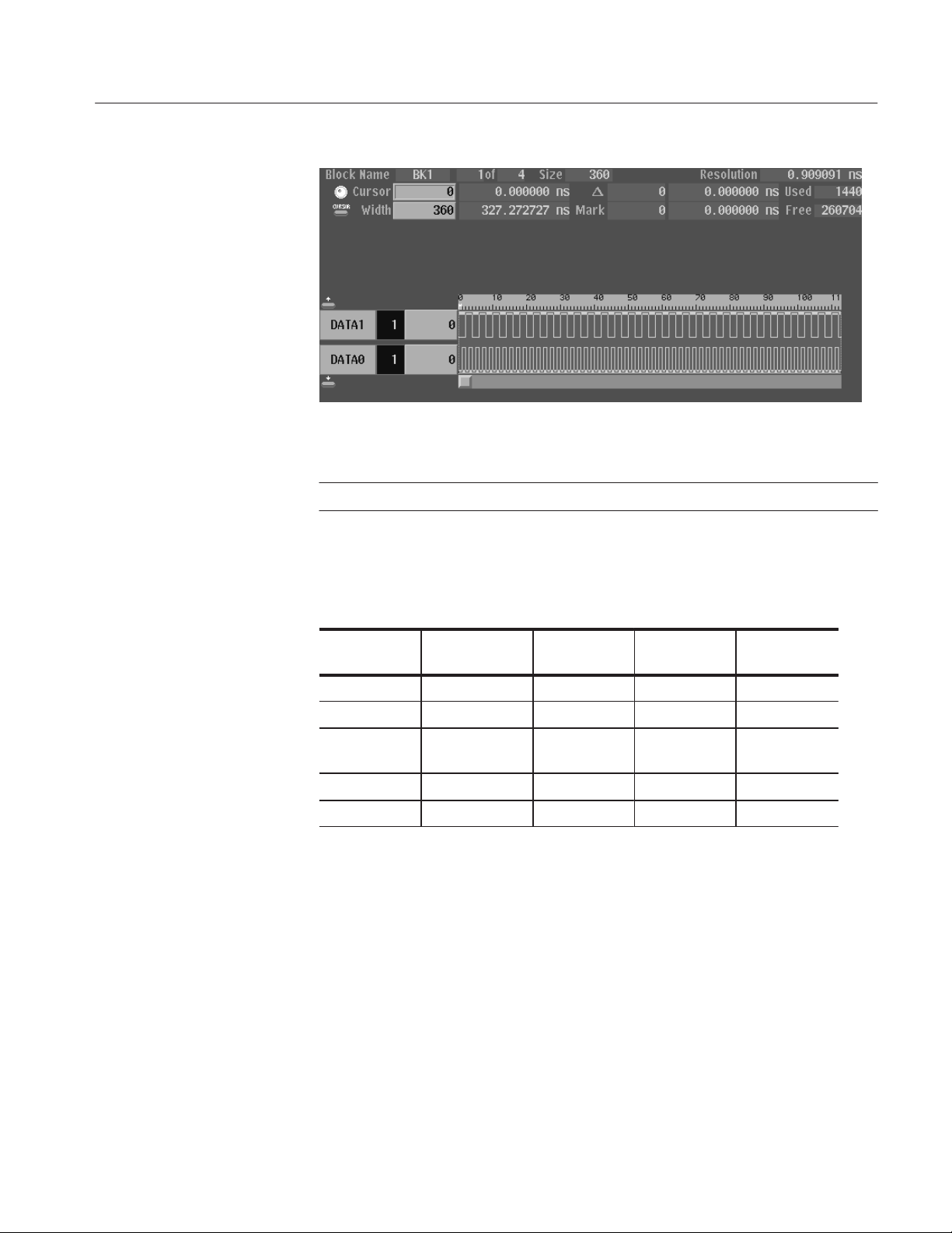
Operating Basics
Figure 2Ć28: Creating a binary upĆcounter for block BK1
NOTE. The block 2 data is all zeros. The data can be used as is without editing.
9. Create binary down-counter data in block 3. Confirm that the knob icon
appears in the Cursor window in the upper left area of the screen. If the icon
is not in that window, move it there with the front-panel CURSOR button.
FrontĆpanel
Menu button Bottom button PopĆup menu Side button
Execute
Action
Binary down
counter
OK 1
OK EXECUTE
button
720
ENTER
ENTER
DG2040 Data Generator
2Ć41
Page 72

Operating Basics
Figure 2Ć29: Creating a binary downĆcounter for block BK3
10. Create data consisting of all ones in block 4. Confirm that the knob icon
appears in the Cursor window in the upper left area of the screen. If the icon
is not in that window, move it there with the front-panel CURSOR button.
Menu button Bottom button PopĆup menu Side button
Execute
Action
Set data to
High
OK EXECUTE
FrontĆpanel
button
1080
ENTER
2Ć42
DG2040 Data Generator
Page 73

Operating Basics
11. Create one subsequence as shown in the example in Figure 2-30
Figure 2Ć30: Sample subsequence
When you call the subsequence, the following outputs are made:
.
H The pattern in BK1 is output 10 times.
H The BK2 pattern is output once.
H The BK3 pattern is output once.
H The BK4 pattern is output 20 times.
Create a sequence as shown in Figure 2-31 and define each line as a block or
subsequence. The lines defined with the subsequence are called and executed
when the sequence is executed.
The lines defined with subsequences are highlighted within the BLOCK column.
Refer to Figure 2-30.
DG2040 Data Generator
2Ć43
Page 74

Operating Basics
Figure 2Ć31: Sample sequence
ON
ON
R
3
The sample sequence in Figure 2-31 is performed as follows:
H Line 0: Wait trigger event and then call the subsequence.
H Line 1: Wait trigger event and then call the subsequence.
H Line 2: While waiting event signal, the BK1 pattern is repeatedly output.
When the event condition has been satisfied, the process jumps to the line 3.
H Line 3: The BK4 pattern is output.
The following two steps create the subsequence:
12. Open the Make Subsequence pop-up menu.
FrontĆpanel
Menu button Bottom button PopĆup menu Side button
Make
Sequence
Special
Edit SubĆ
Sequence
New
button
2Ć44
DG2040 Data Generator
Page 75

Operating Basics
13. Create the lines in the pop-up menu and assign the name SUB1 to the
subsequence.
FrontĆpanel
Menu button Bottom button popĆup menu Side button
Insert
Select the BK1 from the Select block popĆup menu using the frontĆpanel knob.
OK
Repeat 10
With the frontĆpanel down arrow button, advance the line pointer to the next line. See
Figure 2Ć32.
Using the same procedures as above, insert BK2, BK3 and BK4 into the line 1, 2 and 3,
respectively, and set the repeat count to 20 for the BK4.
OK
button
ENTER
Line Pointer
Figure 2Ć32: Line pointer
Clear String
SUB1 OK
Go Back
Go Back
DG2040 Data Generator
2Ć45
Page 76
Operating Basics
Do the following three steps to create the sequence:
14. Create line 0 and line 1 in the sequence.
FrontĆpanel
Menu button Bottom button PopĆup menu Side button
Insert
Select the SUB1 from the Select block and SubĆsequence popĆup menu using the
frontĆpanel knob.
OK
Set Enhanced
Control
Trig Wait
(Set to On)
Go Back
With the frontĆpanel down arrow button, advance the line pointer to the next line.
button
Using above procedures, insert SUB1 into the line 1 and set the Trig Wait.
15. Create line 2 and line 3. Note that you cannot set the jump address (line
number) that has not been created. The jump condition is set in step.
FrontĆpanel
Menu button Bottom button popĆup menu Side button
Insert
Select the BK1 from the Select block and SubĆsequence popĆup menu using the
frontĆpanel knob.
OK
Set Enhanced
Control
Repeat
(Set to Infinite)
Go Back
With the frontĆpanel down arrow button, advance the line pointer to the next line.
Using above procedures, insert BK4 into the line 3.
button
2Ć46
DG2040 Data Generator
Page 77

Operating Basics
16. Create line 3 and then terminate the editing.
FrontĆpanel
Menu button Bottom button popĆup menu Side button
With the frontĆpanel up arrow button, move the line pointer back to the line 2.
Set Enhanced
Control
Event Jump
(Set to On)
Jump to 3
Go Back
button
ENTER
The following two steps set the trigger and run mode for output.
17. Set the trigger source to external and the trigger interval to off.
FrontĆpanel
Menu button Bottom button popĆup menu Side button
SETUP Trigger Source
(Set to Ext)
Interval
State
(Set to Off)
Go Back
button
18. Set the run mode to Enhanced.
FrontĆpanel
Menu button Bottom button popĆup menu Side button
Run Mode Enhanced
button
NOTE. When the run mode is set to Enhanced, the displayed settings in the
ENHANCED columns of the Make Sequence menu become gray. See
Figure 2-33.
DG2040 Data Generator
2Ć47
Page 78

Operating Basics
19. Output the sequence and observe the pattern using an oscilloscope. Refer to
Figure 2-25 on page 2-36 for the connections between the DG2040 Data
Generator and the oscilloscope.
Press START/STOP button on the front-panel to start the output. The
message, Waiting for Trigger, is displayed in the upper right part of the
screen.
The first two lines in the sequence wait for a trigger event. Press the
FORCE TRIGGER button on the front-panel to generate the trigger event.
The sequence in line 2 outputs the BK1 pattern repeatedly until the event
condition is satisfied. Press the STEP/EVENT button on the front-panel to
quit the loop and to advance to sequence line 3.
In Enhanced mode, the entire sequence is repeatedly output. So the message
Waiting for Trigger is displayed again and again until you press the
START/STOP button on the front-panel.
2Ć48
Figure 2Ć33: Sample sequence
20. Exit sequence creation mode and save the data in a file. Name the file SEQ1.
FrontĆpanel
Menu button Bottom button popĆup menu Side button
Insert a formatted 3.5 inch floppy disk into the 3.5 inch floppy disk drive.
File Save Data &
Setup
button
DG2040 Data Generator
Page 79

Operating Basics
FrontĆpanel
Menu button
Side buttonpopĆup menuBottom button
Clear String
SEQ1 OK
button
The file called SEQ1.PDA is created. If a file of the same name already
exists, a message asking if that file should be overwritten will be displayed.
Press OK once more if that message is displayed.
Tutorial 5: Controlling
Pattern Edges
The instrument has a function to move the specified pattern edges within the
range of "100 ps relative to the original position. You can specify the pattern
edge(s) in the DATA0 by using the DATA1 pattern.
In the following procedures, you create the pattern in the DATA0 as shown in
Figure 2-34, in which the highlighted edges are controlled and moved.
DATA1
DATA0
10 points 10 points
Figure 2Ć34: Pattern and edges to be controlled in the DATA0
To specify those edges to be controlled, you also create the pattern in the DATA1
as shown in Figure 2-34.
1. Follow the steps below to create a pattern in the DATA0.
DG2040 Data Generator
a. Reset to factory setting.
Menu button Bottom button popĆup menu Side button
UTILITY System Reset to FactoĆ
ry
OK
FrontĆpanel
button
2Ć49
Page 80

Operating Basics
b. Set the clock pattern.
Menu button Bottom button popĆup menu Side button
EDIT Enhanced Action Clock Pattern
OK
Low Data
(Set 10)
Select High Data by pressing the frontĆpanel up and down arrow buttons.
High Data
(Set 10)
OK
2. Create a pattern in the DATA1.
FrontĆpanel
button
Menu button Bottom button Popup menu Side button
Select DATA1 by pressing the front panel up and down arrow buttons.
Execute Action Numeric input OK
OK EXECUTE
Move cursor to point 9.
Move cursor to point 29.
Move cursor to point 39.
Move cursor to point 49.
3. Set the instrument edge control to On.
Menu button Bottom button popĆup menu Side button
APPLICATION Edge Control Edge Ctrl
(Select On.)
Front panel
button
1
1
1
1
FrontĆpanel
button
2Ć50
Press EDIT button to display edit screen.
DG2040 Data Generator
Page 81

Operating Basics
The edges to be controlled are highlighted. Figure 2-35 shows the created
patterns and highlighted edges.
Figure 2Ć35: Created pattern and highlighted edges
Follow the steps below to change the edge position:
4. Connect the DG2040 to the oscilloscope. Refer to Figure 2-25 on page 2-36.
5. Press the START/STOP button on the front-panel to start output.
6. Set the trigger to CH2 in the oscilloscope. Adjust the oscilloscope setting to
display the DATA0 pattern output.
7. Change the edge position.
FrontĆpanel
Menu button Bottom button popĆup menu Side button
APPLICATION Edge Control Position Offset
button
8. Change the edge position with the general-purpose knob. Use the oscillo-
scope to verify that the edge was moved.
For example, when an output signal has been input from a function generator
(Tektronix AFG310) to the EDGE CONTROL INPUT on the DG2040 front
panel, you can continuously change the specified edge position.
DG2040 Data Generator
2Ć51
Page 82

Operating Basics
Connect SYNC OUT
connector on the rear panel
DG2040 Data Generator Oscilloscope
CH0
SMA termination
SMAĂfemaleĆtoĆBNC
male adapter
BNC Cable
SMA Cable
Figure 2Ć36: DG2040 and oscilloscope connection
CH1
CH2
2Ć52
DG2040 Data Generator
Page 83

Reference
Edit Menu Screen
This section provides the following information:
H Description of the Edit, Setup, Application, and Utility menus.
H Procedures for editing pattern data and creating sequences.
H Procedures for defining groups, setting up channels, setting operating modes,
and triggers.
H Procedures for setting and saving instrument settings.
This section describes the EDIT menu screen shown in Figure 3-1. Table 3-1
provides a description and page number references.
15
14
2 3 4 5
1
12
11
10
6
7 8 9
10
11
12
13
9
Figure 3Ć1: EDIT menu (timing display)
DG2040 Data Generator
3Ć1
Page 84

Reference
Table 3Ć1: Edit menu display
Screen
Reference
1 Displays the point position of the cursor pointer, and the time
Function Page
from the start of the data. When the knob icon is displayed at
the left edge, the cursor can be moved with the general
purpose knob.
3Ć1 and 2Ć23
2 The block name. Also the adjacent area is used to display the
position of the current block with respect to the total number of
blocks. There is only one block in the example shown in the
figure, and currently the block UNNAMED is being displayed.
3 Displays a M to mark the position of the reference. 3Ć1 and 3Ć19
4 The cursor 3Ć1 and 2Ć23
5 Displays the memory size of the block at the cursor position. 3Ć1 and 3Ć19
6 Displays the difference between the reference mark (3) and the
cursor as a number of points and also as a time.
7 Displays the position of the reference mark (3) as a point value
and as a time.
8 The area cursor. The area enclosed by this cursor is the object
of the execute action editing operations. The area is set by the
Set scope (vertical) in the Execute Action menu and Width
(horizontal) items.
9 Displays the time per point. 3Ć1
10 Displays the total memory size for all blocks. 3Ć1
11 Displays the size of the remaining available memory. 3Ć1
12 A scale which shows point positions. 3Ć1
13 Display area for the pattern data. 3Ć1
3Ć1 and 3Ć28
3Ć1 and 3Ć19
3Ć1 and 3Ć19
3Ć1 and 2Ć23
3Ć2
14 Describes the current action of the arrow buttons. 3Ć21
15 Displays the value of the data at the cursor position (4). 3Ć1
16 Displays the number of bits in the data bit group. 3Ć1
17 Describes the function of the front panel EXECUTE button.
Pressing the EXECUTE button executes the editing function for
the indicated cursor position or area.
18 Indicates the data bits or the data bit groups. Data bits that are
set up to be the object of editing operations are displayed at a
higher intensity (bright).
19 Displays the width of the area cursor as a number of points and
as a time.
3Ć32
3Ć1
3Ć1
DG2040 Data Generator
Page 85

Menu Trees
Reference
Menu trees are shown for the EDIT, SETUP, APPLICATION, and UTILITY
menus.
Edit Menu Tree
Figure 3-2 shows the bottom and side or pop-up menus associated with the Edit
menu.
MENU Button Bottom Menu Side Menu or popĆup Menu
EDIT
File
Settings
Block
Load Data & Setup
Save Data & Setup
Import Data
Export Data
New
Place mark here
Set memory size
Select arrow key function
Set view type to timing
Set view type to table
Set view type to binary
Set view type to numeric
Show overview
Set numeric view format
Move to block start
Move to block end
Move to next block
Move to previous block
Move to block(any)
Add block delimiter here
Delete current block delimiter
Rename current block
Resize current block
Figure 3Ć2: Edit Menu tree
DG2040 Data Generator
3Ć3
Page 86

Reference
MENU Button Bottom Menu Side Menu or popĆup Menu
EDIT
Execute Action
Set scope
Cut
Copy
Paste Ć insert
Paste Ć replace
Set data to high
Set data to low
Insert high data
Insert low data
Invert data
Mirror vertical
Mirror horizontal
Magnify
Numeric input
Shift left (add zero)
Shift right (add zero)
Shift left
Shift right
Rotate left
Rotate right
Binary up counter
Binary down counter
Johnson counter
Graycode counter
Enhanced Action
Make Sequence
Figure 3Ć2: Edit Menu tree (cont)
3Ć4
Clock Pattern
Shift Register Generator
Logical Operation
Bit Operation
Serial Code Converter
Insert
Delete
Repeat Count
Set Enhanced Control
Special
Trig Wait
Event Jump
Jump to
Repeat
Delete All
Make Simple Sequence
Edit SubĆSequence
DG2040 Data Generator
Page 87

Reference
Setup Menu Tree
MENU button Bottom menu Side menu
SETUP
Group Assign
Output Condition
Level Condition
Timing Condition
Run Mode
Figure 3-3 shows the bottom and side menus associated with the Setup menu.
Add Group
Delete Group
Rename
Group Bit(s) Config
Reset All bits Assign
Assign Condition
Control Condition
High
Low
Delay
Repeat
Single
Step
Enhanced
Update
Event Level
Event Enable/Disable
Trigger Slope
Trigger Level
Impedance
Source
Interval
Clock
Reference
Int FREQ
Ext FREQ
Figure 3Ć3: Setup Menu tree
Application Menu Tree
Figure 3-4 shows the bottom and side menus associated with the Application
menu.
MENU button Bottom menu Side menu
APPLICATION
Edge Control
Edge Ctrl
Position Offset
Figure 3Ć4: Application Menu tree
State
Time
DG2040 Data Generator
3Ć5
Page 88

Reference
Utility Menu Tree
MENU Button Bottom Menu Side Menu or Base Menu
UTILITY
Figure 3-5 shows the bottom and side menus associated with the Utility menu.
Mass Memory Change Directory
Make Directory
Rename
Copy or Delete
Special Initialize Media
Display/Hardcopy Display Clock
Hardcopy Format
Clear Message Area
Copy
Delete
Delete All
Catalog Order
Lock
Brightness
Dimmer
Port
Figure 3Ć5: Utility Menu tree
System Remote Port
GPIB
Serial Baud rate
Power up Pause
Date/Time
Reset to Factory
Security Immediate
Status
Diag
Type
Execute
Configure
Address
Data Bits
Parity
Stop Bits
Handshake
3Ć6
DG2040 Data Generator
Page 89

Reference
Edit Menu Functions
Table 3-2 lists the functions of the EDIT menu items and the pages where their
documentation appears.
Table 3Ć2: EDIT menu functions
Bottom Base or side menu Function Page
File
Settings
Block
Load Data & Setup Loading pattern data and setup parameters 3Ć9
Save Data & Setup Saving pattern data and setup parameters 3Ć9
Import Data Loading pattern data from mass memory 3Ć10
Export Data Writing pattern data to mass memory 3Ć15
New Initialization for data creation 3Ć18
Place mark here Setting the reference mark 3Ć19
Set memory size Setting the memory size 3Ć19
Select arrow key function Setting the operation of the arrow buttons 3Ć20
Set view type to timing
Set view type to table
Set view type to binary
Set view type to numeric
Show overview Setting the pattern data display format
Set numeric view format Setting the numeric view format 3Ć27
Move to block start
Move to block end
Move to next block
Move to previous block
Move to block( any)
Add block delimiter here Delimiting blocks 3Ć29
Delete current block delimiter Combining blocks 3Ć30
Rename current block Changing a block name 3Ć31
Resize current block Changing the size of a block 3Ć31
Setting the pattern data display format 3Ć22
Moving the cursor for the block 3Ć28
DG2040 Data Generator
3Ć7
Page 90

Reference
Table 3Ć2: EDIT menu functions (Cont.)
Bottom PageFunctionBase or side menu
Execute Action
Enhanced Action
Set scope Setting the scope 3Ć34
Cut Deleting pattern data 3Ć35
Copy Copying pattern data 3Ć35
Paste Ć insert Pasting (inserting) pattern data 3Ć35
Paste Ć replace Pasting (replacing) pattern data 3Ć36
Set data to high Setting pattern data to high 3Ć36
Set data to low Setting pattern data to low 3Ć36
Insert high data Inserting high data 3Ć37
Insert low data Inserting low data 3Ć37
Invert data Inverting data 3Ć37
Mirror vertical Swapping pattern data in the vertical direction 3Ć38
Mirror horizontal Swapping pattern data in the horizontal direction 3Ć39
Magnify Magnifying pattern data 3Ć39
Numeric input Inputting pattern data numerically 3Ć39
Shift left (add zero) or
Shift right (add zero)
Shift left or Shift right Shifting pattern data left or right 3Ć41
Shift up (add zero) or
Shift down (add zero)
Shift left or Shift right Shifting pattern data left or right 3Ć40
Rotate left or Rotate right Rotating pattern data left or right 3Ć43
Rotate up or Rotate down Rotating pattern data up or down 3Ć43
Binary up counter
Binary down counter
Johnson counter
Graycode counter
Clock Pattern Clock pattern generation 3Ć45
Shift Register Generator Pseudorandom pulse generation 3Ć47
Logical Operation Logical operations between pattern data items 3Ć50
Bit Operation Moving or copying pattern data 3Ć52
Serial Code Converter Serial code data conversion 3Ć53
Shifting pattern data left or right by inserting zeros 3Ć40
Shifting pattern data up or down by inserting zeros 3Ć40
Creating standard pattern data 3Ć44
3Ć8
DG2040 Data Generator
Page 91
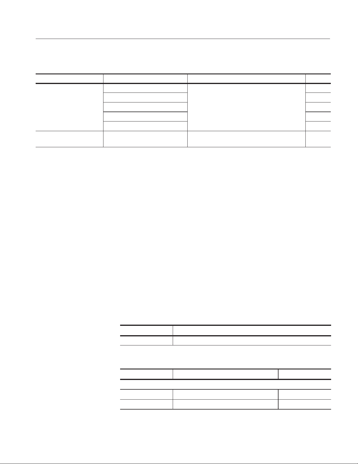
Table 3Ć2: EDIT menu functions (Cont.)
Bottom PageFunctionBase or side menu
Make Sequence
Undo Cancel the latest operation and restore the previous
Insert
Delete 3Ć59
Repeat Count 3Ć59
Set Enhanced Control 3Ć59
Special 3Ć60
Sequence definition
setting
File Menu
This subsection contains information on the bottom menu functions for the Edit
Menu.
The File menu saves and loads data between the instruments internal memory
and mass memory (3.5 inch floppy disk). When the File bottom menu item is
selected, a side menu with Load Data & Setup, Save Data & Setup, Import,
Export, and New items is displayed.
Reference
3Ć58
3Ć63
Load Data & Setup
The Load Data & Setup function reads format pattern data, block, group,
sequence and setup data into the instruments internal memory from mass
memory (3.5 inch floppy disk).
The DG2040 Data Generator can read data created and stored from the DG2000
series. The DG2040 will use the pattern data in the lower 2 bits. Also, the
DG2040 Data Generator can read DG2000 series setup information except for
those settings that are not common to both platforms.
Submenu
Item
Change Directory Changes the current directory.
Operation. Do the following to load the pattern data and setup parameters.
Bottom button PopĆup menu Side button
Insert a 3.5 inch floppy disk in the floppy disk drive.
File Load Data & Setup
Function
Select the file to be loaded. OK
DG2040 Data Generator
3Ć9
Page 92
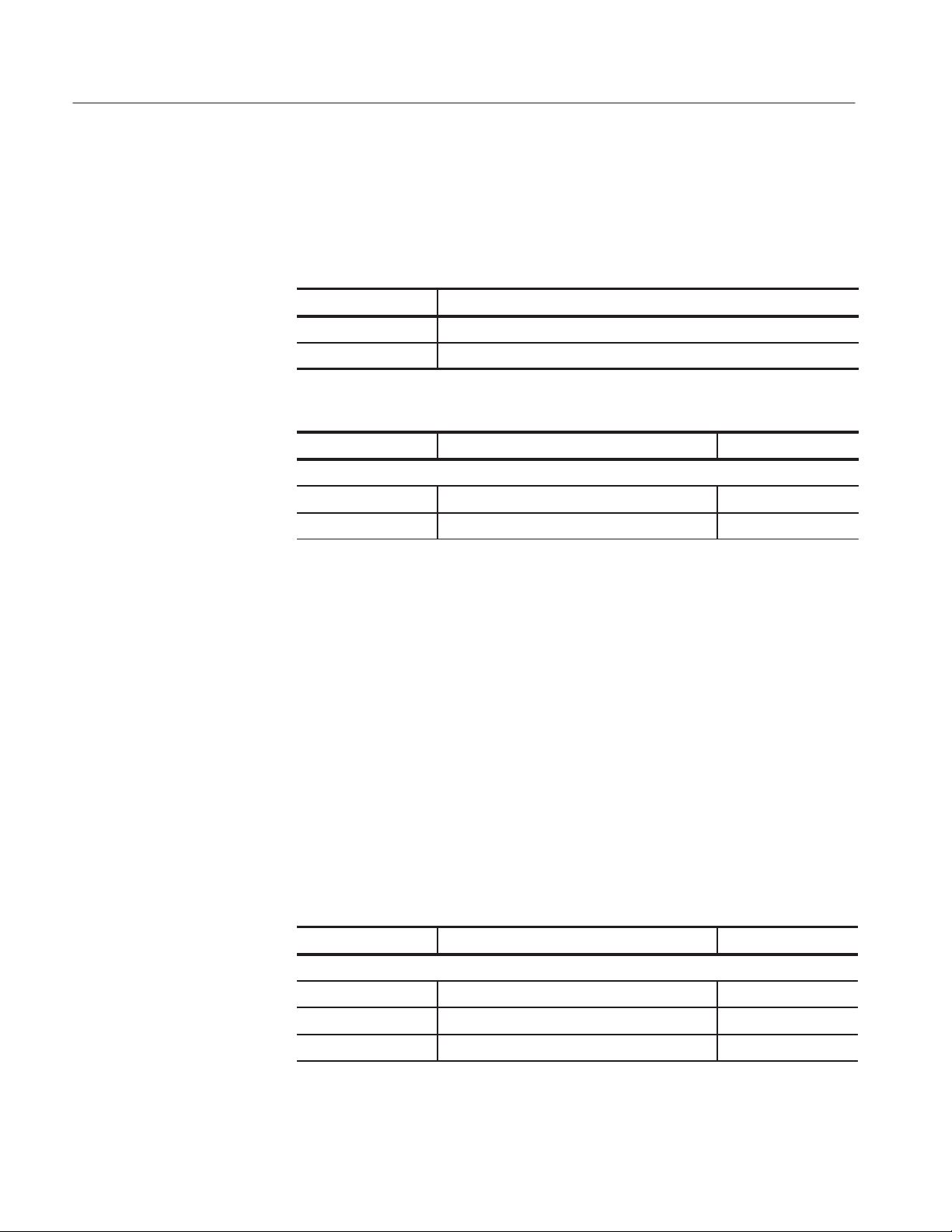
Reference
Save Data & Setup
Import
The Save Data & Setup functions stores the pattern data, block, group, sequence
and setup data from the instruments internal memory to mass memory (3.5 inch
floppy disk) in the DG2040 Data Generator format.
Submenu
Item
Clear String Deletes the current displayed string.
Change Directory Changes the current directory.
Operation Do the following to save the pattern data and setup parameters:
Bottom button PopĆup menu Side button
Insert a writeĆenabled 3.5 inch floppy disk in the floppy disk drive.
File Save Data & Setup
Function
Enter the file name for the data to be saved. OK
The Import function loads the pattern data from mass memory (3.5 inch floppy
disk) into pattern memory. The DG2040 can read the following data formats:
H Tektronix TDS series waveform data (file extension: .WFM)
H Tektronix TLS series group data (file extension: .GRP)
H Tektronix AWG2000 series waveform data (file extension: .WFM)
H Tektronix DG2000-Series and DG2040 Data Generator waveform data (file
extension: .PDA)
H CSV format data (file extension: .CSV). Refer to page 3-13 for instructions
regarding formatting data in a CSV format.
Pop-up menu parameter settings are used to specify the read-in method.
Operation. Do the following to import pattern data from mass memory.
Bottom button PopĆup menu Side button
Insert the 3.5 inch floppy disk in the drive.
File Import Data
Select the file to be read in. OK
Change the parameters as required. OK
3Ć10
DG2040 Data Generator
Page 93

Reference
PopĆup Menu. Figure 3-6 shows the data read-in configuration window. The
parameters that appear in this window differ depending on which data format
was read in.
Figure 3Ć6: Import Configuration Menu (File format: AWG2000 series waveform file)
Table 3-3 describes the input parameters.
Table 3Ć3: Import parameters
Parameter Function
Destination Sets the place where the readĆin data is to be written. Either Pattern
memory or the Paste buffer can be selected. If data is read into the
paste buffer, data can be pasted to the data bit specified by the Paste
item in the Execute Action menu.
Read Point(s) Sets the number of data points to be read. Data in excess of the
specified memory size cannot be read in.
Source Start Specifies the starting position from which the data is read in from the
file.
Source MSB Specifies the position of the MSB from which data in the file will be
read.
Dest Start Specifies the position which data is read in when pattern memory is the
destination.
Dest MSB Specifies the position of the MSB to which data will be written when
pattern memory is the destination.
DG2040 Data Generator
Read type Sets the data readĆin method when pattern memory is the destination.
Either Insert or Overwrite can be selected.
3Ć11
Page 94

Reference
Table 3Ć3: Import parameters (Cont.)
Parameter Function
Convert to Bin When this setting is set to ON, the waveform is compared to a
threshold level and the data is converted to binary. RP binary data from
the Tektronix TDS and TLS series products are read in as RI data. The
data cannot be converted to binary data if it is left in the RP state.
Threshold Sets the threshold level used to convert readĆin data to binary when the
Convert to Bin parameter is set to ON.
With Marker Data Sets whether or not marker data is read, in addition to waveform data,
for Tektronix AWG2000 series waveform file format data.
Figures 3-7 and 3-8 show the data write operations in terms of point positions
and data bit positions when pattern memory is the write destination.
Number of data
Start Position
(Source Start)
points read
(Read Points)
ReadĆin Data
(Read type:Overwrite)
Pattern Memory
Initial position where
data is written
(Dest Start)
Figure 3Ć7: Data write in terms of point positions
ReadĆin Method
3Ć12
DG2040 Data Generator
Page 95

Reference
Á
Á
Á
Á
Á
Á
WithĂMarkerĂData:ĂON
ReadĆin Data
(AWG2000 Series
Waveform Data)
PatternMemory
10
Data Write MSB Setting
(Dest MSB)
WithĂMarkerĂData:ĂOFF
ReadĆin Data
(AWG2000 Series
Waveform Data)
PatternMemory
Data Write MSB Setting
10
(Dest MSB)
Data Read MSB Setting
(Source MSB)
D11Mk1
Mk2 D10 D5 D4 D3
Data Read MSB Setting
(Source MSB)
D11Mk1
Mk2 D10 D5 D4 D3
D9
CSV Data Format
Figure 3Ć8: Data write in terms of data bit positions
The DG2040 Data Generator can import vector data from the built-in floppy
drive using a simple ASCII Comma Separated Variable (CSV) format. This
section defines how the data is formatted for importing into the DG2040 Data
Generator. The CSV format is defined as follows:
<1DB0><Comma><1DB1><Comma>.....<1DBx><CR>
БББББББББББББ
<2DB0><Comma><2DB1><Comma>.....<2DBx><CR>
... ... ... ... ...
... ...
БББББББББББББ
<yDB0><Comma><yDB1><Comma>.....<yDBx><CR>
БББББББББББББ
! The number of bits (x) defines
ББББББББ
the width of the pattern
! Second word
ББББББББ
! The number of lines (y) defines
the depth of the pattern
ББББББББ
When formatting data in the CSV format, note the following:
H Each data byte is defined by the ASCII character: zero <0>, ASCII 48 or one
<1>, ASCII 49
DG2040 Data Generator
3Ć13
Page 96

Reference
H Each data byte is separated by the ASCII character: comma <,> (ASCII 44),
space (ASCII 32), or TAB (ASCII 9)
H Each line is terminated with the ASCII character: carriage return <CR>,
ASCII 13
H The number of bits in a line defines the word width. For example, if the first
line consists of pattern: 1,0,1,1 then the word width is 4-bits wide
H For Importing, the specified 2 bit wide data can be imported. For Exporting ,
the specified one bit or two bits can be exported to a file.
H The number of lines in the file defines the number of words in the pattern.
For example, 10 lines defines 10 data words.
H The DG2040 Data Generator CSV format file is a DOS-compatible file
formatted as defined above with a .CSV file extension.
CSV Format Example. To export a 2-bit pattern that is 3 words long, create the
following data, as an example, and save it using filename: PATTERN.CSV. This
can be created using a spreadsheet program, a text editor, or a custom filter
program to convert data from one format to another.
1,1<CR>
0,1<CR>
0,0<CR>
NOTE. Bit pattern data must have at least 360 words. The above pattern data
cannot be read into the DG2040 Data Generator. Note that this is a simple
example.
Once the data words have been imported, parameters including clock rate, output
levels and interchannel timing need to be set since the CSV format does not
transfer this information. After all operating parameters have been set, the entire
pattern can be stored on a floppy for nonvolatile storage. The entire pattern will
fit on one floppy since the DG2040 Data Generator uses an instrument specific
binary format that is more compact than ASCII format.
Importing Large Data Files. It may be possible to create a large CSV file.
Depending on what kind of operation is currently performed, the DG2040 Data
Generator may not allocate the internal work space for creating CSV format data
larger than 128 K words. An extreme example is a 2-bit wide word pattern that
has 262144 (256 K) words. For the data to fit into the work space and onto a 3.5
inch floppy disk capacity, the pattern must be segmented into 128 K (131072
words) blocks and saved to a separate 3.5 inch floppy disks. To import the data
do the following:
3Ć14
DG2040 Data Generator
Page 97

Reference
1. Insert the 3.5 inch floppy disk with the first 128 K words into the drive.
2. Select File ! Import Data and select a file to be imported.
3. Press the OK button. The Import Configuration pop-up menu appears. This
menu allows you to configure how the data will be imported. In this
example, only the Dest Start point will be modified.
4. Set the Dest Start point to zero for the first 3.5 inch floppy disk.
5. Set the Dest Start point to 65536 for the second 3.5 inch floppy disk.
6. Set the Dest Start point to 131072 for the third 3.5 inch floppy disk.
7. Repeat the steps above changing the Dest Start point until the data from the
last 3.5 inch floppy disk is read.
Once the data words have been imported, parameters including clock rate, output
levels, and interchange timing need to be set, since the CSV format does not
transfer this information.
Export
The Export function writes pattern data to mass memory (3.5 inch floppy disk).
Data is written either as CSV data or as Tektronix AWG2000-Series waveform
data. The write method is specified by setting a parameter in a pop-up menu.
NOTE. Icon data and hardware setup data are not saved in the output AWG2000
Series waveform data. When this data is read in to an AWG2000 Series
instrument, default setup data will be added. PCs and some other systems may
not be able to read this data directly.
Operation. Do the following to write pattern data to mass memory.
Bottom button PopĆup menu Side button
Insert a writeĆenabled 3.5 inch floppy disk in the floppy disk drive.
File Export Data
Select the format of the data to be written
(either CSV data or AWG2000s Waveform
data).
Enter the file name for the data to be written. OK
Change the parameters as required. OK
OK
DG2040 Data Generator
3Ć15
Page 98

Reference
Pattern data will be written for
bits for which this indicator is on.
PopĆup Menu. Figure 3-9 shows the configuration windows for the two formats.
CSV Format
Figure 3Ć9: The Export Config menu
When CSV format is selected, the instrument displays a menu for selecting
which bits should be written to the file, delimiter symbols, and other parameters.
Table 3-4 describes the parameter items that are set using this menu.
AWG2000 Series Format
Table 3Ć4: Export parameters
Parameter Function
Export Data Bit Specifies the data bits to be written to the pattern data. Bits for which
this indicator is on are written. Bits can be selected using the general
purpose knob, and the on/off state can be changed with the left and right
arrow buttons. Consecutive bits can be turned on or off using the 1 and
0 numeric keys.
Column separator Sets the line separator symbol. The delimiter symbols are usually used
as follows:
CR+LF: MSĆDOS and Windows
LF: UNIX
CR: Macintosh
3Ć16
Data separator Sets the interbit delimiter. Comma, space, or tab can be selected for this
parameter. Comma is the most common setting.
From This field is valid when Entered is specified for the Region in the
submenu. It specifies the starting position for the data written.
Size This field is valid when Entered is specified for the Region in the
submenu. It specifies the number of data points written.
DG2040 Data Generator
Page 99

Reference
When the AWG2000 Series format is selected, a menu that allocates data for a
total of 14 bits, MARKER 1 and 2 and DATA00 to DATA11, is displayed. Use
the arrow buttons to select the AWG2000 Series bit and use the general purpose
knob to allocate the DG2040 Data Generator bit. Allocate all bits to be written
by repeating this operation.
Submenu
Item
Set All Data bits
(CSV only)
Clear All Data bits
(CSV only)
Region When this setting is set to All, the whole data area is written, and when
Function
Sets the data bit write settings for all data bits.
Clears the data bit write settings for all data bits.
it is set to Entered, the data in the area specified by From and Size is
written.
Exporting Large Data. The DG2040 Data Generator’s internal memory capacity
can not export a 2-bit wide pattern data in CSV format that is larger than 131072
(128 K) words. The data that is to be written onto a 3.5 inch floppy disk must
have the pattern segmented into 128 K (131072 words) blocks and saved to
separate 3.5 inch floppy disks.
To import large data files, do the following:
1. Insert a 3.5 inch floppy disk into the drive.
2. Select the File ! Export Data to display Export Data Format pop-up menu.
3. Select CSV data and then press the OK side button.
DG2040 Data Generator
4. Enter a file name and then press the OK side button. The Export Config
(CSV) pop-up menu appears. This menu allows you to configure how the
data will be exported. In this example, only the Size and From will be
modified.
5. Confirm that the Region is set to Entered. If it is not set correctly, press the
Region side button to set to Entered.
6. Enter 0 into the From and 131072 into the Size, and then press the OK side
button.
7. Repeat the procedures from Step 2 through Step 6, changing the file name
and incrementing From point by 131072 until all pattern data are stored into
3.5 inch floppy disks. Note that two blocks of 32 K word pattern data in the
CSV format can be stored in a 3.5-inch 2HD floppy disk.
3Ć17
Page 100
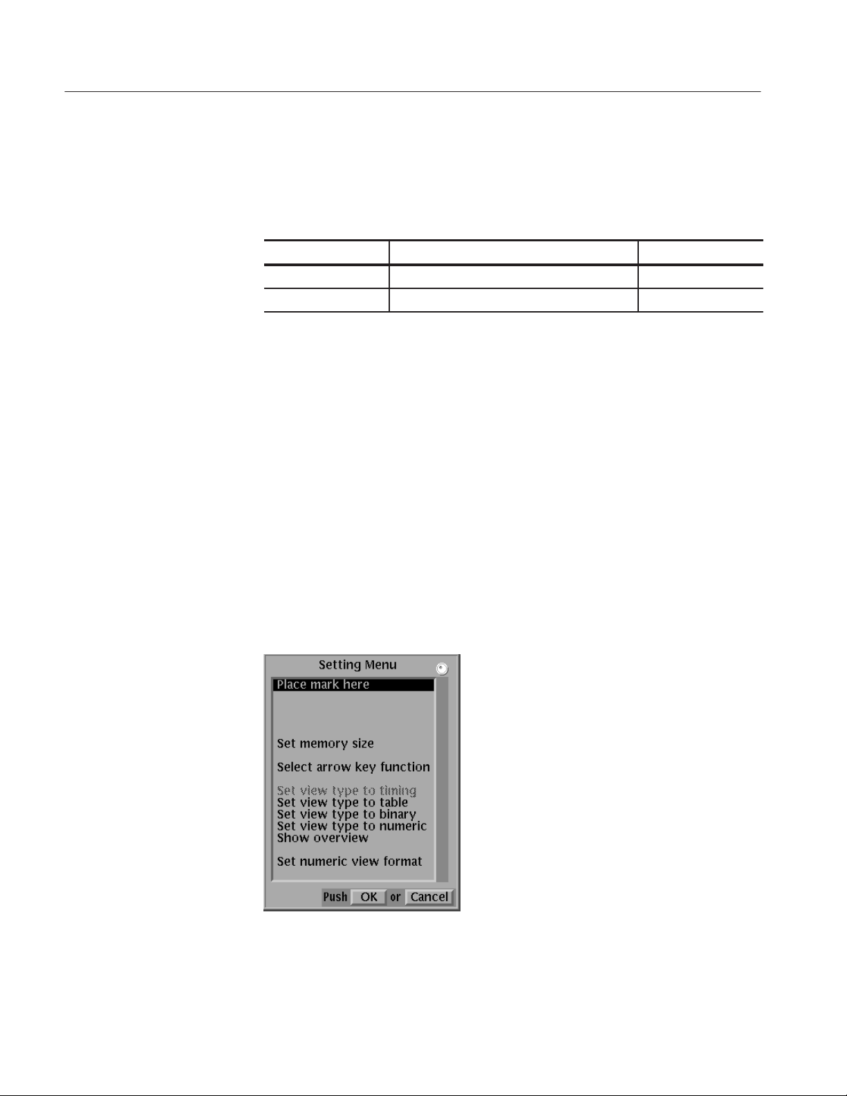
Reference
Settings Menu
New
The New function initializes all data, including the pattern data, the block
divisions, and the sequence data to the default state.
Operation. Do the following to initialize for pattern data creation:.
Bottom button PopĆup menu Side button
File New
OK
The settings menu sets all the EDIT menu internal settings and supports the
following operations:
H Setting the reference mark
H Setting the reference group
H Setting the memory size
H Setting the arrow button operating mode
H Setting the display type (format)
The item to be set is selected from the pop-up list using the general purpose
knob. Figure 3-10 shows the pop-up menu.
Figure 3Ć10: Settings popĆup menu
3Ć18
DG2040 Data Generator
 Loading...