

Page 1

Programmer Manual
DG2030
Data Generator
071-0057-50
This document applies to firmware version 1.00
and above.
www.tektronix.com
Page 2

Copyright © T ektronix, Inc. All rights reserved.
T ektronix products are covered by U.S. and foreign patents, issued and pending. Information in this publication supercedes
that in all previously published material. Specifications and price change privileges reserved.
T ektronix, Inc., P.O. Box 500, Beaverton, OR 97077
TEKTRONIX and TEK are registered trademarks of T ektronix, Inc.
Page 3

Table of Contents
Getting Started
Command Syntax
Preface v. . . . . . . . . . . . . . . . . . . . . . . . . . . . . . . . . . . . . . . . . . . . . . . . . . .
Getting Started 1-1. . . . . . . . . . . . . . . . . . . . . . . . . . . . . . . . . . . . . . . . . . . .
Choosing an Interface 1-2. . . . . . . . . . . . . . . . . . . . . . . . . . . . . . . . . . . . . . . . . . . . .
Installing for GPIB Communication 1-3. . . . . . . . . . . . . . . . . . . . . . . . . . . . . . . . . .
Installing for RS-232-C Communication 1-6. . . . . . . . . . . . . . . . . . . . . . . . . . . . . . .
Command Syntax 2-1. . . . . . . . . . . . . . . . . . . . . . . . . . . . . . . . . . . . . . . . . .
Command Notation 2-1. . . . . . . . . . . . . . . . . . . . . . . . . . . . . . . . . . . . . . . . . . . . . . .
Program and Response Messages 2-1. . . . . . . . . . . . . . . . . . . . . . . . . . . . . . . . . . . .
Command and Query Structure 2-2. . . . . . . . . . . . . . . . . . . . . . . . . . . . . . . . . . . . . .
Character Encoding 2-2. . . . . . . . . . . . . . . . . . . . . . . . . . . . . . . . . . . . . . . . . . . . . . .
Syntactic Delimiters 2-3. . . . . . . . . . . . . . . . . . . . . . . . . . . . . . . . . . . . . . . . . . . . . . .
White Space 2-3. . . . . . . . . . . . . . . . . . . . . . . . . . . . . . . . . . . . . . . . . . . . . . . . . . . . .
Special Characters 2-3. . . . . . . . . . . . . . . . . . . . . . . . . . . . . . . . . . . . . . . . . . . . . . . .
Arguments 2-4. . . . . . . . . . . . . . . . . . . . . . . . . . . . . . . . . . . . . . . . . . . . . . . . . . . . . .
Header 2-6. . . . . . . . . . . . . . . . . . . . . . . . . . . . . . . . . . . . . . . . . . . . . . . . . . . . . . . . .
Concatenating Commands 2-8. . . . . . . . . . . . . . . . . . . . . . . . . . . . . . . . . . . . . . . . . .
Query Responses 2-9. . . . . . . . . . . . . . . . . . . . . . . . . . . . . . . . . . . . . . . . . . . . . . . . .
Other General Command Conventions 2-10. . . . . . . . . . . . . . . . . . . . . . . . . . . . . . . .
Command Groups 2-11. . . . . . . . . . . . . . . . . . . . . . . . . . . . . . . . . . . . . . . . . .
Command Summaries 2-11. . . . . . . . . . . . . . . . . . . . . . . . . . . . . . . . . . . . . . . . . . . . .
Command Descriptions 2-19. . . . . . . . . . . . . . . . . . . . . . . . . . . . . . . . . . . . . .
Retrieving Response Messages 2-125. . . . . . . . . . . . . . . . . . . . . . . . . . . . . . . .
Status and Event Reporting
Status and Event Reporting 3-1. . . . . . . . . . . . . . . . . . . . . . . . . . . . . . . . . .
Registers 3-1. . . . . . . . . . . . . . . . . . . . . . . . . . . . . . . . . . . . . . . . . . . . . . . . . . . . . . . .
Queues 3-5. . . . . . . . . . . . . . . . . . . . . . . . . . . . . . . . . . . . . . . . . . . . . . . . . . . . . . . . .
Processing Sequence 3-6. . . . . . . . . . . . . . . . . . . . . . . . . . . . . . . . . . . . . . . . . . . . . .
Messages 3-9. . . . . . . . . . . . . . . . . . . . . . . . . . . . . . . . . . . . . . . . . . . . . . . . . .
Programming Examples
Programming Examples 4-1. . . . . . . . . . . . . . . . . . . . . . . . . . . . . . . . . . . . .
Overview of the Sample Programs 4-1. . . . . . . . . . . . . . . . . . . . . . . . . . . . . . . . . . .
Required Execution Environment 4-2. . . . . . . . . . . . . . . . . . . . . . . . . . . . . . . . . . . .
Floppy Disk Files 4-3. . . . . . . . . . . . . . . . . . . . . . . . . . . . . . . . . . . . . . . . . . . . . . . . .
Installing and Compiling the Programs 4-4. . . . . . . . . . . . . . . . . . . . . . . . . . . . . . . .
Sample Program Functions and Usage 4-6. . . . . . . . . . . . . . . . . . . . . . . . . . . . . . . .
DG2030 Programmer Manual
i
Page 4

Table of Contents
Appendices
Glossary & Index
Appendix A: Character Charts A–1. . . . . . . . . . . . . . . . . . . . . . . . . . . . . . .
Appendix B: Reserved Words B–1. . . . . . . . . . . . . . . . . . . . . . . . . . . . . . . .
Appendix C: Interface Specification C–1. . . . . . . . . . . . . . . . . . . . . . . . . . .
Interface Functions C–1. . . . . . . . . . . . . . . . . . . . . . . . . . . . . . . . . . . . . . . . . . . . . . . .
Interface Messages C–2. . . . . . . . . . . . . . . . . . . . . . . . . . . . . . . . . . . . . . . . . . . . . . . .
Appendix D: Factory Initialization Settings D–1. . . . . . . . . . . . . . . . . . . . .
Glossary Glossary–1. . . . . . . . . . . . . . . . . . . . . . . . . . . . . . . . . . . . . . . . . . . . . .
Index Index–1. . . . . . . . . . . . . . . . . . . . . . . . . . . . . . . . . . . . . . . . . . . . . . . . .
ii
DG2030 Programmer Manual
Page 5

List of Figures
Table of Contents
Figure 1-1: Functional layers in GPIB system 1-1. . . . . . . . . . . . . . . . . . .
Figure 1-2: GPIB connector 1-3. . . . . . . . . . . . . . . . . . . . . . . . . . . . . . . . . .
Figure 1-3: GPIb system configurations 1-4. . . . . . . . . . . . . . . . . . . . . . . .
Figure 1-4: GPIB parameter settings 1-5. . . . . . . . . . . . . . . . . . . . . . . . . .
Figure 1-5: RS-232-C point-to-point connection 1-6. . . . . . . . . . . . . . . . .
Figure 1-6: RS-232-C port 1-7. . . . . . . . . . . . . . . . . . . . . . . . . . . . . . . . . . .
Figure 1-7: Pin assignments of 9-pin and
25-pin D-type shell connector 1-8. . . . . . . . . . . . . . . . . . . . . . . . . . . . .
Figure 1-8: Typical RS-232-C cable wiring requirements 1-8. . . . . . . . . .
Figure 1-9: RS-232-C parameter settings 1-9. . . . . . . . . . . . . . . . . . . . . . .
Figure 2-1: Command and query structure flowchart 2-2. . . . . . . . . . . .
Figure 2-2: ABSTouch arguments and associated controls 2-20. . . . . . . . .
Figure 2-3: GPIB: Retrieving Response Messages 2-125. . . . . . . . . . . . . . . .
Figure 2-4: RS-232-C: Retrieving Response Messages 2-125. . . . . . . . . . . .
Figure 3-1: The Standard Event Status (SESR) 3-2. . . . . . . . . . . . . . . . . .
Figure 3-2: The Status Byte Register (SBR) 3-3. . . . . . . . . . . . . . . . . . . . .
Figure 3-3: The Device Event Status Enable Register (DESER) 3-4. . . .
Figure 3-4: The Event Status Enable Register (ESER) 3-4. . . . . . . . . . . .
Figure 3-5: The Service Request Enable Register (SRER) 3-5. . . . . . . . .
Figure 3-6: Status and event handling process overview 3-7. . . . . . . . . . .
DG2030 Programmer Manual
iii
Page 6

Table of Contents
List of Tables
Table 1-1: GPIB and RS-232-C comparison 1-2. . . . . . . . . . . . . . . . . . . .
Table 2-1: BNF symbols and meanings 2-1. . . . . . . . . . . . . . . . . . . . . . . .
Table 2-2: Decimal Numeric Notation 2-4. . . . . . . . . . . . . . . . . . . . . . . . .
Table 2-3: Header in query responses 2-9. . . . . . . . . . . . . . . . . . . . . . . . . .
Table 2-4: DATA commands 2-11. . . . . . . . . . . . . . . . . . . . . . . . . . . . . . . . .
Table 2-5: DEBUG Commands 2-12. . . . . . . . . . . . . . . . . . . . . . . . . . . . . . .
Table 2-6: DIAGNOSTIC commands 2-13. . . . . . . . . . . . . . . . . . . . . . . . . .
Table 2-7: DISPLAY commands 2-13. . . . . . . . . . . . . . . . . . . . . . . . . . . . . .
Table 2-8: HARDCOPY commands 2-14. . . . . . . . . . . . . . . . . . . . . . . . . . .
Table 2-9: MEMORY commands 2-14. . . . . . . . . . . . . . . . . . . . . . . . . . . . .
Table 2-10: MODE commands 2-15. . . . . . . . . . . . . . . . . . . . . . . . . . . . . . .
Table 2-11: OUTPUT commands 2-15. . . . . . . . . . . . . . . . . . . . . . . . . . . . .
Table 2-12: SOURCE commands 2-16. . . . . . . . . . . . . . . . . . . . . . . . . . . . .
Table 2-13: SYSTEM commands 2-16. . . . . . . . . . . . . . . . . . . . . . . . . . . . .
Table 2-14: TRIGGER commands 2-17. . . . . . . . . . . . . . . . . . . . . . . . . . . .
Table 2-15: Other commands 2-17. . . . . . . . . . . . . . . . . . . . . . . . . . . . . . . .
Table 3-1: SESR bit functions 3-2. . . . . . . . . . . . . . . . . . . . . . . . . . . . . . . .
Table 3-2: SBR bit functions 3-3. . . . . . . . . . . . . . . . . . . . . . . . . . . . . . . . .
Table 3-3: Definition of event codes 3-9. . . . . . . . . . . . . . . . . . . . . . . . . . .
Table 3-4: Normal condition 3-10. . . . . . . . . . . . . . . . . . . . . . . . . . . . . . . . .
Table 3-5: Command errors (CME Bit:5) 3-10. . . . . . . . . . . . . . . . . . . . . .
Table 3-6: Execution errors (EXE Bit:4) 3-12. . . . . . . . . . . . . . . . . . . . . . .
Table 3-7: Internal device errors (DDE Bit:3) 3-14. . . . . . . . . . . . . . . . . . .
Table 3-8: System event and query errors 3-14. . . . . . . . . . . . . . . . . . . . . .
Table 3-9: Warnings (EXE Bit:4) 3-15. . . . . . . . . . . . . . . . . . . . . . . . . . . . .
Table 3-10: Device-dependent command execution errors 3-15. . . . . . . . .
Table 3-11: Extended device specific errors 3-17. . . . . . . . . . . . . . . . . . . . .
Table A–1: The DG2020 Character Set A–1. . . . . . . . . . . . . . . . . . . . . . . . .
Table A–2: ASCII & GPIB Code Chart A–2. . . . . . . . . . . . . . . . . . . . . . . .
Table C–1: GPIB interface function implementation C–1. . . . . . . . . . . . .
Table C–2: GPIB interface messages C–2. . . . . . . . . . . . . . . . . . . . . . . . . .
Table D–1: Factory initialized settings D–1. . . . . . . . . . . . . . . . . . . . . . . . .
iv
DG2030 Programmer Manual
Page 7

Preface
This is the Programmer Manual for the DG2030 Data Generator. This manual
provides information on operating the instrument over a General Purpose
Interface Bus (GPIB) interface or an RS-232-C interface.
This manual provides the following information:
H Getting Started describes how to connect and set up for remote operation.
H Syntax and Commands defines the command syntax and processing
conventions and describes each command in the data generator command
set.
H Status and Events explains the status information and event messages
reported by the data generator.
H Appendices contains various topics of use to the programmer.
H Glossary and Index contains a glossary of common terms and an index to
this manual.
Related Manuals
Other documentation for the data generator includes:
H The DG2030 User Manual (Tektronix part number 071-0059-XX) describes
the operation of the instrument.
H The DG2030 Service Manual (Tektronix part number 071-0058-XX)
provides information for maintaining and servicing the Data Generator.
DG2030 Programmer Manual
v
Page 8

Preface
vi
DG2030 Programmer Manual
Page 9
Getting Started
The Data Generator has two interfaces for remote operation: the GPIB interface
and the RS-232-C interface. All menu-controlled and front-panel controlled
functions, except the ON/STBY function, the edit function, and the GPIB and
RS-232-C parameter setup functions, can be performed through the GPIB or the
RS-232-C interface using the programming command set (described in
Section 2).
The GPIB interface conforms to ANSI/IEEE Std 488.1-1987, which specifies the
hardware interface, its basic functional protocol, and a set of interface messages
(codes) that control the interface functions. This instrument also conforms to
ANSI/IEEE Std 488.2-1987 which specifies Codes, Formats, Protocols, and
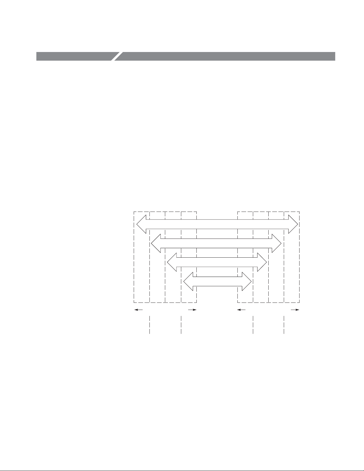
Common Commands to support the system application. The functional layers of
the GPIB system are shown in Figure 1-1.
BUS
DeviceĆspecific Messages
Common Commands and Queries
Syntax and Data Structures
Remote INTFC Messages
CBA ABCD
D
System Component x System Component y
Specified
by
Device
IEEE 488.2
Standard
A: Interface Function Layer
B: Message Communication Function Layer
C: Common System Function Layer
D: Device Function Layer
IEEE 488.1
Standard
Figure 1Ć1: Functional layers in GPIB system
IEEE 488.2
Standard
Specified
by
Device
DG2030 Programmer Manual
1Ć1
Page 10

Getting Started
Choosing an Interface
The RS-232-C interface, which was established by the Electronic Industries
Association (EIA), provides a common basis of serial communication between
devices that exchange data. This interface has long been used on terminals,
modems, printers, and other devices. The RS-232-C interface that the data
generator provides also uses most of the same codes, formats, protocols, and
common commands as are used with the GPIB interface (ANSI/IEEE
Std 488.2-1987).
Your system hardware may let you choose which interface to use with your
system; if so, you should consider the advantages and disadvantages of each
interface. For example, the GPIB interface is an eight-bit parallel bus and
therefore it offers high-speed data transfers and multiple instrument control. In
contrast, the RS-232-C interface is a slower serial data bus for single instrument
control, but it is easy to connect to and can be used with a low-cost controller.
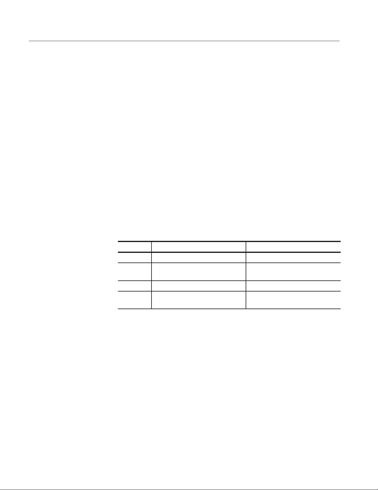
Table 1-1 compares the GPIB and RS-232-C interface.
Table 1Ć1: GPIB and RSĆ232ĆC comparison
Operating attribute GPIB RSĆ232ĆC
Cable ANSI/IEEE Std 488 9Ćwire (DCE)
Data flow control Hardware, 3Ćwire handshake Flagging: soft (XON/XOFF),
hard (DTR/CTS)
Data format 8Ćbit parallel 8Ćbit serial
Interface control Operator lowĆlevel control
message
Interface messages Most ANSI/IEEE Std 488 Device clear via ASCII break
Interrupts reported Service requests
status and event code
Message termination
(Receive)
Message termination
(Transmit)
Timing Asynchronous Asynchronous
Transmission path length ≤2 meters between devices;
Speed 200 Kbytes/sec 19,200 bits/sec
Hardware EOI, software LF, or
both
Hardware EOI, and softwareLFSoftware LF
≤20 meters total cabling for
GPIB system
None
signal
Status and event code
(no service requests)
Software CR, LF, or CR and
LF
≤15 meters
1Ć2
System environment Multiple devices (≤15) Single terminal (point to point
connection)
DG2030 Programmer Manual
Page 11

Installing for GPIB Communication
With the power off, connect a GPIB cable from the GPIB controller to the
ANSI/IEEE Std 488 port (GPIB) connector on the rear panel of the data
generator (see Figure 1-2). For example, when using an MS-DOS compatible
controller, connect the GPIB cable between the National Instrument PC2A GPIB
board and the data generator GPIB connector.
GPIB Connector
Getting Started
DG2030 Programmer Manual
Figure 1Ć2: GPIB connector
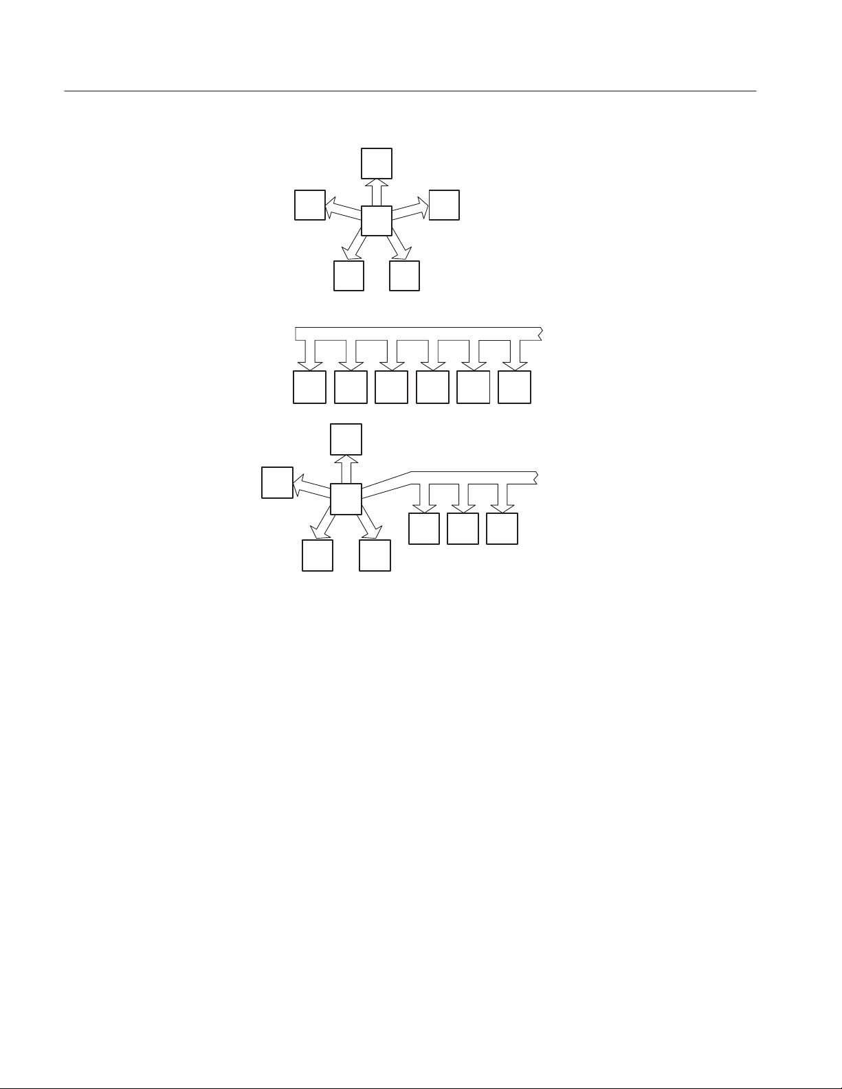
Instruments can be connected to the GPIB in linear or star configurations or in a
combination of both configurations. A linear hookup is one where a GPIB cable
is used to string one device to a second, and then another GPIB cable is used to
string from a second to a third, and so on until all devices in the system are
connected. A star setup is one where one end of all the GPIB cables in the
system are attached to one device. Refer to Figure 1-3 for these GPIB system
configurations.
1Ć3
Page 12
Getting Started
C
Star Configuration
B D
A
Restrictions
F
A
D
B C D E F
E
A
C
E
Linear Configuration
Combination of Star and
Linear Configurations
F
G H
B
Figure 1Ć3: GPIb system configurations
Consider the following restrictions when distributing instruments on the GPIB
bus:
1Ć4
1. No more than 15 total devices (including the controller) can be included on a
signal bus.
2. In order to maintain the electrical characteristics of the bus, one device load
must be connected for every two meters of cable (most often, each device
represents one device load to the bus).
3. The total cable length (cumulative) must not exceed 66 feet (20 meters).
4. At least two-thirds of the device loads must be powered on.
DG2030 Programmer Manual
Page 13
Getting Started
Setting the GPIB
Parameters
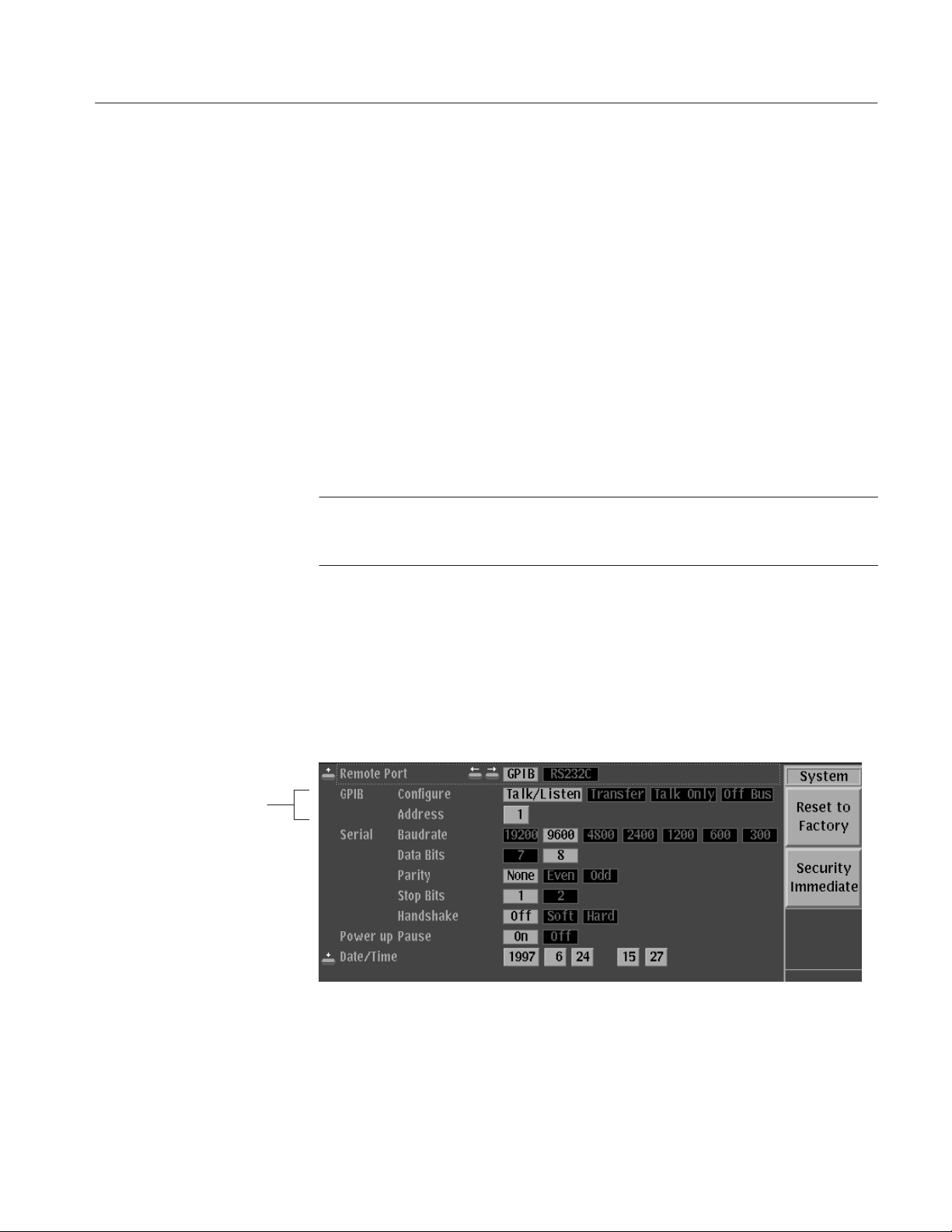
To set the GPIB parameters, proceed as follows:
1. Press the UTILITY button in the MENU column to the right of the screen.
The UTILITY menu appears above the bottom menu buttons.
2. Press the System bottom menu button to display the System menu (See
Figure 1-4).
3. Select the Configure item from the GPIB menu using the up and down arrow
buttons. Set the GPIB operating mode using the left and right arrow buttons.
H Talk/Listen. Sets the communications mode to talk/listen.
H Talk Only. Sets the communications mode to talk only, which is used for
hardcopy output.
H Off Bus. Logically disconnect the data generator from GPIB system.
NOTE. The data generator accepts as a terminator either the software LF (Line
Feed), sent as the last data byte, or the hardware EOI, with the EOI line asserted
concurrently with the last data byte sent.
4. Select the Address item from the GPIB menu using the up and down arrow
buttons. Then use the rotary knob to set the primary address to a value in the
range 0 to 30.
GPIB Menu
5. Select the Remote Port item using the up and down arrow buttons, and
additionally, highlight “GPIB” using the left and right arrow buttons. This
selects the GPIB as the remote interface.
Figure 1Ć4: GPIB parameter settings
DG2030 Programmer Manual
1Ć5
Page 14
Getting Started
Installing for RSĆ232ĆC Communication
Connect an RS-232-C cable from the computer terminal to the RS-232-C
connector on the rear panel of the data generator. Use a configuration based on
the settings for the data flow control (flagging).
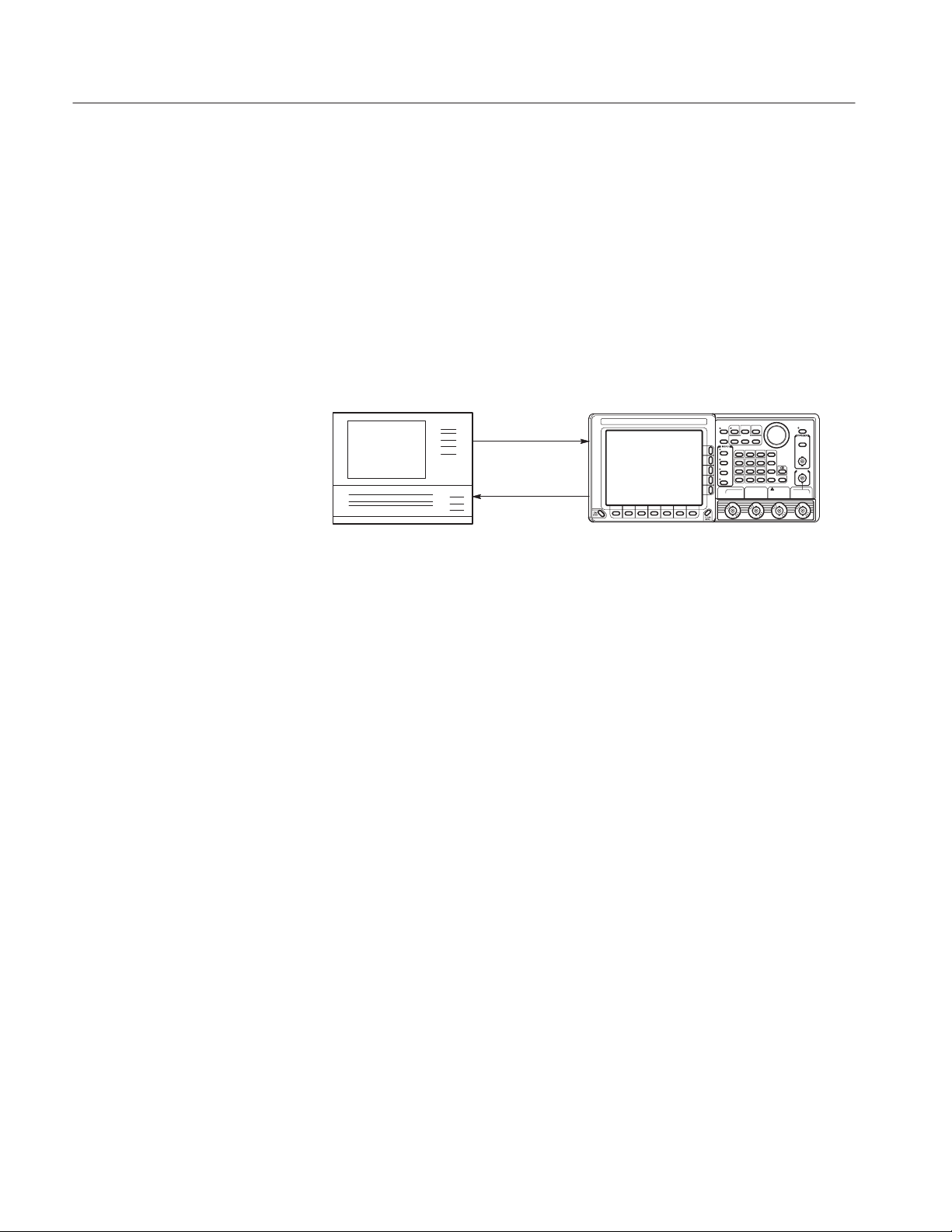
The RS-232-C provides a point-to-point connected communication interface
between two devices (see Figure 1-5). The data generator can transmit and
receive the same message serially over the RS-232-C interface as it can in
parallel over the GPIB interface.
Controller
Figure 1Ć5: RSĆ232ĆC pointĆtoĆpoint connection
Several connectors are used with the RS-232-C interface: a DTE device uses a
standard 25-pin male D-type shell connector; a DCE device uses a standard
25-pin female D-type shell connector. Some recent computers implement the
RS-232-C interface using 9-pin D-type connector.
This data generator uses a standard 9-pin D-type shell connector, provided on the
rear panel (see Figure 1-6), along with a 9-pin male to 25-pin male conversion
cable. Figure 1-7 on page 1-8 shows both 9-pin and 25 pin connectors with
their pin number assignments.
DG2030
1Ć6
DG2030 Programmer Manual
Page 15
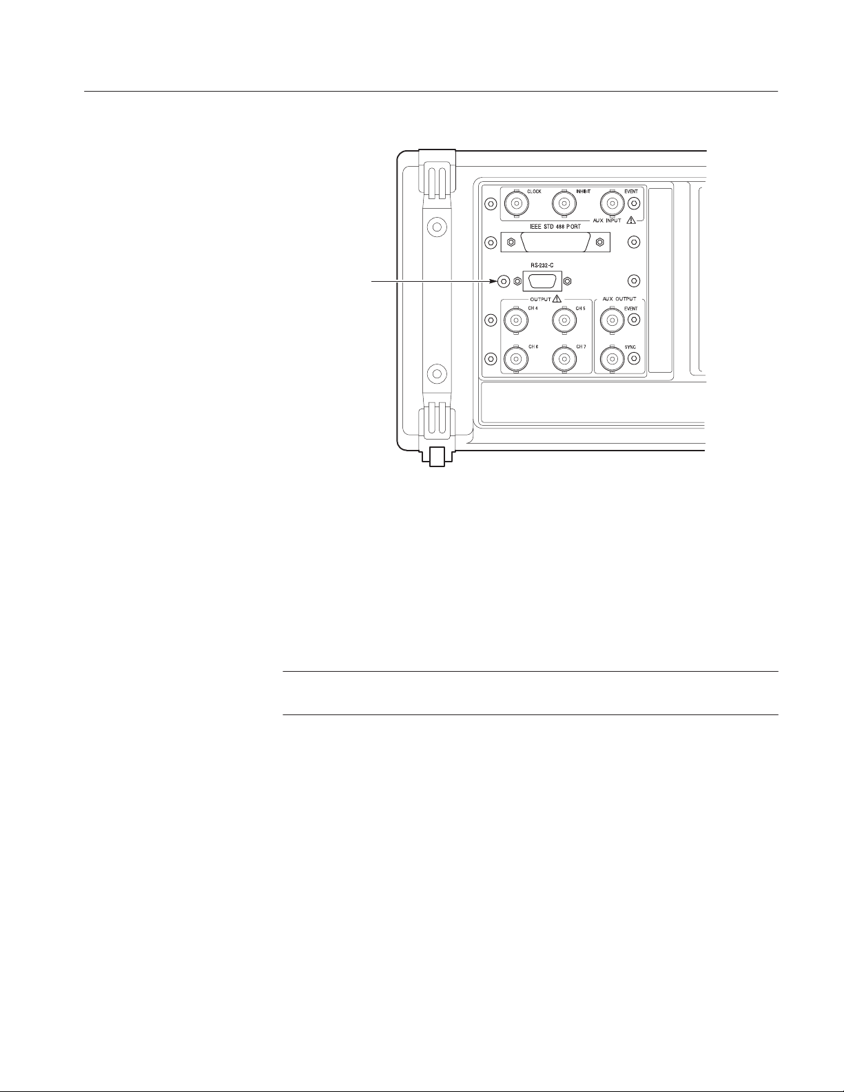
RSĆ232ĆC
Connector
Getting Started
Figure 1Ć6: RSĆ232ĆC port
This data generator is designed as DCE device. You may connect it up to
15 meters (50 feet) from a DTE device using a straight-through male-to-female
cable. However, if the other device is instead configured as a DCE device, you
will need a special adapter or null-modem cable for local DCE-to-DCE
communications. Refer to the wiring examples in the Figure 1-8 for the proper
signal connections between devices.
NOTE.
available.
In this data generator, only TxD, RxD, DTR, CTS pins and Signal Ground are
DG2030 Programmer Manual
1Ć7
Page 16

Getting Started
Pin
9ĆPIN DĆSHELL
1
2
6
7
8
9
NOTE: TxD, RxD, DTR, CTS and Ground lines are only available
in the data generator.
Receive Data (RxD) 3
2
3 Transmit Data (TxD) 2
3
4 Data Terminal Ready (DTR) 20
4
5 Signal Ground 7
5
8 Clear to Send (CTS) 5
25ĆPIN DĆSHELL
14
15
16
17
18
19
20
21
22
23
24
25
1
2
3
4
5
6
7
8
9
10
11
12
13
Figure 1Ć7: Pin assignments of 9Ćpin and 25Ćpin DĆtype shell connector
Pin Pin Pin
2
3
4
5
8
9Ćpin DCE to 9Ćpin DTE 9Ćpin DCE to 9Ćpin DCE
2
3
4
5
8
2
3
4
5
8
2
3
4
5
8
Pin Pin
2
3
4
5
8
9Ćpin DCE to 25Ćpin DTE
NOTE: When using software flow control, the CTSĆDTR lines do not need to be connected.
2
3
5
7
20
Pin Pin
2
3
4
5
8
Figure 1Ć8: Typical RSĆ232ĆC cable wiring requirements
1Ć8
2
3
5
7
20
9Ćpin DCE to 25Ćpin DCE
DG2030 Programmer Manual
Page 17
Getting Started
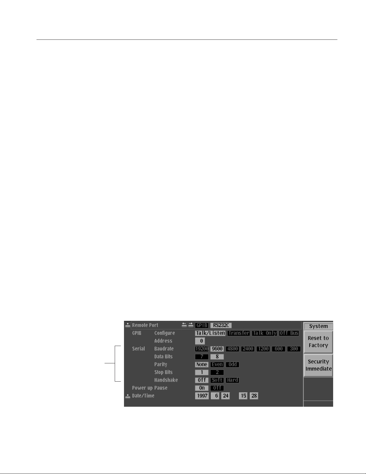
Setting the RSĆ232
Parameters
To set the RS-232-C parameters, perform the following steps:
1. Press the UTILITY button in the MENU column to the right of the screen.
The UTILITY menu appears above the bottom menu buttons.
2. Press the System bottom menu button to display the System menu
(See Figure 1-9).
3. Select the Baudrate item from the Serial menu using the up and down arrow
buttons. Here select the data transfer rate using the left and right arrow
buttons. The rate can be set to 300, 600, 1200, 2400, 4800, 9600, or 19200
baud.
4. Select the Data Bits item from the Serial menu using the up and down arrow
buttons. Then use the left and right arrow buttons to select the data bit length
for each character. The bit length can be set to either 7 or 8 bits.
5. Select the Parity item from the Serial menu using the up and down arrow
buttons. Then use the left and right arrow buttons to set the error check bit
for each character. The error bit can be set to None, Even, or Odd parity.
6. Select the Stop Bits item from the Serial menu using the up and down arrow
buttons. Then use the left and right arrow buttons to select the number of
stop bits sent after each character. The number of stop bits can be set to
either 1 or 2.
Serial Menu
7. Select the Handshake item from the Serial menu using the up and down
arrow buttons. Then use the left and right arrow buttons to select the method
of controlling the flow of data between devices. The data flow method can
be set to Hard (DTR/CTS), Soft (XON/XOFF), and Off (no flow control).
8. Select the Remote Port item using the up and down arrow buttons, and
additionally, highlight “RS232C” using the left and right arrow buttons.
This selects the RS-232-C interface as the remote interface.
Figure 1Ć9: RSĆ232ĆC parameter settings
DG2030 Programmer Manual
1Ć9
Page 18

Getting Started
1Ć10
DG2030 Programmer Manual
Page 19

Command Syntax
The DG2030 provides a large set of commands to control the operations and
functions of the data generator from an external controller. This section describes
the syntax and communication rules for using these commands to operate the
data generator.
Command Notation
The command syntax is in extended BNF (Backus-Naur Form) notation. The
extended BNF symbols used in the command set are shown in the following
table.
Table 2Ć1: BNF symbols and meanings
Symbol Meaning
<ą> Indicates a defined element
| Delimits Exclusive OR elements
{ą} Delimits a group of elements one of which the programmer must select
[ą] Delimits an optional element that the programmer may omit
[ą]... Delimits an optional element that the programmer may omit or may repeat one
::= Indicates that the left member is defined as shown by the the right member
Program and Response Messages
Programs created or placed in an external controller are transferred to the data
generator as a program message. A program message is a sequence of zero or
more program message units delimited by the program message unit delimiter,
the semicolon (;).
A program message unit is a set command or query command. The data
generator performs a function or changes a setting or mode when it receives a set
command; when it receives a query command, it returns measurement data,
settings, status codes and/or status messages. The data generator transfers these
response messages to the external controller.
or more times
DG2030 Programmer Manual
2Ć1
Page 20
Command Syntax
Command and Query Structure
Commands are either set commands or query commands (usually just called
commands and queries in this manual). Most commands have both a set form
and query form. The query form of a command is the same as the set form,
except that the query form ends with a question mark.
Figure 2-1 shows a flowchart of the structure of the commands and queries. The
structure of the header is described in detail in Header on page 2-6.
Command
,
Character Encoding
Header
Mnemonic
Argument
,
?
:
:
Header
Mnemonic
Argument
?
,
Argument
,
Argument
Command
Query
Query
Query
Command
Command
Figure 2Ć1: Command and query structure flowchart
The program can be described using the American Standard Code for Information Interchange (ASCII) character encoding.
2Ć2
This seven-bit ASCII code is used for the majority of syntactic elements and
semantic definitions. In special cases, an eight-bit ASCII Code is allowed in the
arbitrary block arguments described on page 2-6. The ASCII code character set
table is found in Appendix A.
DG2030 Programmer Manual
Page 21

Syntactic Delimiters
Command Syntax
Syntactic elements in a program message unit are delimited (differentiated) with
colons, white space, commas, or semicolons.
Colon (:). Typically delimits the compound command header.
MMEMORY:DELETE:ALL, SOURCE:OSCILLATOR:SOURCE
White Space. Typically delimits command/query headers from the argument.
DIAGNOSTIC:SELECT ALL
SYSTEM:DATE 1997,7,7
DIAGNOSTIC:SELECT and SYSTEM:DATE are the command headers, and ALL and
1997,7,7 are the arguments.
Comma (,). Typically delimits between multiple arguments. In the above
example, a comma delimits the multiple arguments 1997, 7 and 7.
White Space
Special Characters
Semicolon (;). Typically delimits between multiple commands (or multiple
program message units). For more information about using the semicolon, refer
to Concatenating Commands on page 2-8.
White space, which is used to delimit certain syntactic elements in a command,
is defined in the data generator as a single ASCII-encoded byte in the range
ASCII 0-32 (decimal). This range consists of the standard ASCII characters
exclusively except for ASCII 10, which is the Line Feed (LF) or New Line (NL)
character.
The Line Feed (LF) character or the New Line (NL) character (ASCII 10) and all
characters in the range of ASCII 127-255 are defined as special characters. These
characters are used in arbitrary block arguments only; using these characters in
other parts of any command yields unpredictable results.
DG2030 Programmer Manual
2Ć3
Page 22
Command Syntax
Arguments
In a command or query, one or more arguments follow the command header. The
argument, sometimes called program data, is a quantity, quality, restriction, or
limit associated with the command or query header. Depending on the command
or query header given, the argument is one of the following types:
H Decimal Numeric
H String
H Arbitrary Block
Decimal Numeric
The data generator defines a decimal numeric argument as one expressed in one
of three numeric representations: NR1, NR2, or NR3. This definition complies
with that found in ANSI/IEEE Std 488.2-1987. Any commands that use
arguments in any of the the first three notations can use a fourth notation NRf
(for Numerical Representation flexible). The four formats are shown in
Table 2-2.
Table 2Ć2: Decimal Numeric Notation
Type Format Examples
NR1 implicitĆpoint (integer) 1, +3, -2, +10, -20
NR2 explicitĆpoint unscaled
(fixed point)
NR3 explicitĆpoint scaled (floating point) 1E+2, +3.36E-2, -1.02E+3
NRf numeric representationĆflexible; any of
NR1, NR2, and NR3 may be used
1, 2, +23.5, -0.15
1, +23.5, -1.02E+3
As just implied, you can use NRf notation for arguments in your programs for
any commands that this manual lists as using any of NR1, NR2, or NR3 notation
in its arguments. Be aware, however, that query response will still be in the
format specified in the command. For example, if the command description is
:DESE <NR1>, you can substitute NR2 or NR3 when using the command in a
program. However, if you use the query :DESE?, the data generator will respond
in the format <NR1> to match the command description in this manual.
2Ć4
Unit and SI Prefix
If the decimal numeric argument refers to a voltage or frequency, you can
express it using SI units instead of in the scaled explicit point input value format
<NR3>. (SI units are units that conform to the Systeme International d’Unites
standard.) For example, you can use the input format 200 mV or 1.0 MHz
instead of 200.0E–3 or 1.0E+6, respectively, to specify voltage or frequency.
DG2030 Programmer Manual
Page 23
Command Syntax
You can omit the unit, but you must include the SI unit prefix. You can use either
upper or lowercase units.
V or v for voltage
Hz, HZ, or hz for frequency
The SI prefixes, which must be included, are shown below. Note that either
lower or upper case prefixes can be used.
String
SI Prefix
Corresponding Power 10
1
1
Note that the prefix m/M indicates 10-3when the decimal numeric argument denotes
voltage, but 10
6
when it denotes frequency.
m/M k/K m/M
-3
10
3
10
6
String, sometimes referred to as a string literal, a literal, or just a string, is
defined as a series of characters enclosed by double quotation marks (”) as in:
"This is a string constant"ąąorąą"0 .. 127"
To include a double quoted character in the string, insert an additional double
quote character ahead of the double quote character in the string. For example,
the string:
serial number "B010000"
would be defined as:
"serial number ""B010000"""
Single quotation marks (’) can also be used instead of double quotation marks.
For instance:
DG2030 Programmer Manual
'serial number ''B010000'''
String constants may be of any length up to the memory limits of the instrument
in which the message is parsed.
2Ć5
Page 24

Command Syntax
Arbitrary Block
An arbitrary block argument is defined as:
#<byte count digit><byte count>[<contiguous eightĆbit data
byte>]...
or:
#<contiguous eightĆbit data byte]... <terminator>
where:
<byte count digit>::= a nonzero digit in the range ASCII 1-9 that defines the
number of digits (bytes) in the <byte count> field.
<byte count>::= any number of digits in the range ASCII 0-9 that define how
many bytes are in the <contiguous 8Ćbit data byte> field.
<contiguous 8Ćbit data byte>::= a <byte count> number of 8-bit bytes in
the range ASCII 0-255 that define the message. Each byte defines one character.
<terminator>::= a software LF followed by a hardware EOI. For example,
#16AB4ZLT<LF><&EOI>
Header
Header Mnemonic
Channel Representation
Header Structure
The header mnemonic represents a header node or a header subfunction. The
command or query header comprises one or more header mnemonics that are
delimited with the colon (:).
The channel can be specified by using the OUTPut:CH<n> header mnemonic in
commands and query commands. The term <n> is a number between 0 and 7
that expresses the specified channel.
Commands and queries can be structured into six basic forms.
H Simple command header
H Simple query header
H Compound command header
H Compound query header
H Common command header
H Common query header
2Ć6
DG2030 Programmer Manual
Page 25

Command Syntax
Figure 2-1 on page 2-2 shows the syntax for all possible structures, and each of
the six basic forms are explained below.
Simple Command Header. A command that contains only one header mnemonic.
It may also contain one or more arguments. Its message format is:
[:]<Header Mnemonic> [<Argument>[,<Argument>]...]
such as:
START
or
STOP
Simple Query Header. A command that contains only one header mnemonic
followed by a question mark (?). Its message format is:
[:]<Header Mnemonic>? [<Argument>[,<Argument>]...]
such as:
HCOPY?
or
TRIGGER?
Compound Command Header. A command that contains multiple header
mnemonics plus argument(s). Its message format is:
[:]<Header Mnemonic>[:<Header Mnemonic>]...
[<Argument>[,<Argument>]...]
such as:
MMEMORY:INITIALIZE HD1
or
SYSTEM:SECURITY:STATE ON
Compound Query Header. A command that contains multiple header mnemonics
followed by a question mark (?). Its message format is:
[:]<Header Mnemonic>[:<Header Mnemonic>]...?
[<Argument>[,<Argument>]...]
DG2030 Programmer Manual
such as:
DIAGNOSTIC:RESULT?
or
DATA:BLOCK:SIZE? "BLOCK1"
2Ć7
Page 26

Command Syntax
Common Command Header. A command that precedes its header mnemonic with
an asterisk (*). Its message format is:
<Header Mnemonic> [<Argument>[,<Argument>]...]
such as:
*RST
The common commands are defined by IEEE Std 488.2 and are common to all
devices which support IEEE Std 488.2 on the GPIB bus.
Common Query Header. A command that precedes its header mnemonic with an
asterisk (*) and follows it with a question mark (?). Its message format is:
<Header Mnemonic>? [<Argument>[,<Argument>]...]
such as:
*IDN?
The common commands are defined by IEEE Std 488.2 and are common to all
devices which support the IEEE Std 488.2 on the GPIB bus.
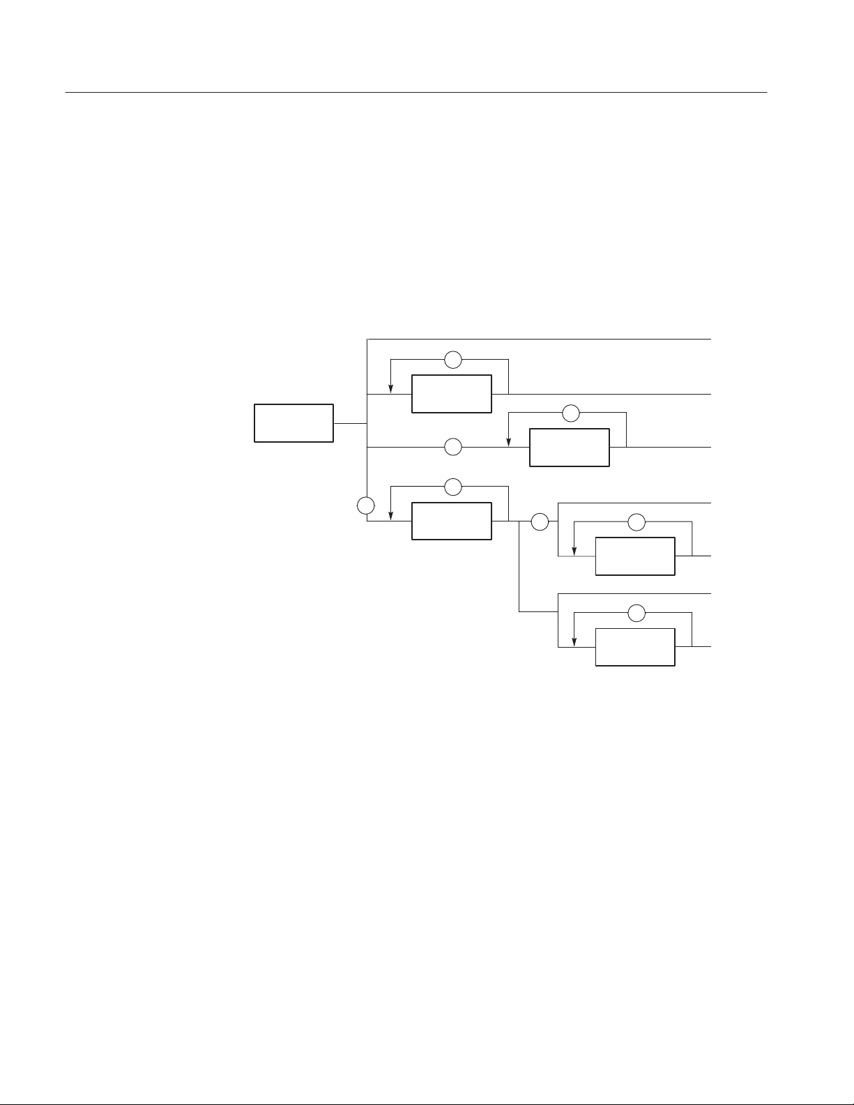
Concatenating Commands
Most of the compound command headers are in a tree structure. The tree
structure of an example command is diagrammed below. Note that the top of the
structure always begins with a colon (:).
BLOCK GROUP MSIZE PATTERN SEQUENCE UPDATE
ADD ADDADD DEFINE DEFINE ... DEFINEBIT BITDELETE ... DELETE ...WORD
The following example of a compound command combines three headers
delimited by semicolons:
:DATA:
:DATA:BLOCK:ADD 512,"BLOCK3"; :DATA:BLOCK:DELETE "BLOCK2";
:DATA:BLOCK:SIZE "BLOCK1",512
2Ć8
DG2030 Programmer Manual
Page 27

Command Syntax
You must include the complete path in each header when there is no common
complete path to the start of the tree structure (the colon). However, note that
part of each header in the above example has a common path :DATA:BLOCK. You
may shorten compound command structures with such headers. For example, the
command above may be rewritten as follows.
:DATA:BLOCK:ADD 512,"BLOCK3"; DELETE "BLOCK2"; SIZE
"BLOCK1",512
Note that the mnemonics :DATA and :BLOCK are assumed from the first header
by the headers that follow. The following command descriptions are valid
examples of commands shortened using the principle just described. (Note that
the insertion of common command (*SRE) between headers does not prevent the
headers that follow from assuming the earlier header mnemonics.)
:DATA:BLOCK:ADD 512,"BLOCK3"; DELETE "BLOCK2";
:DATA:GROUP:DELETE "GROUP4"
:DATA:MSIZE 16384; BLOCK:ADD 512,"BLOCK3"; DELETE "BLOCK2"
Query Responses
:DATA:BLOCK:ADD 512,"BLOCK3"; *SRE?; DELETE "BLOCK2"; SIZE
"BLOCK1",512
The following examples have been shortened incorrectly and cause errors.
:DATA:BLOCK:DELETE "BLOCK2"; DATA:GROUP:DELETE "GROUP4"
:DATA:BLOCK:ADD 512,"BLOCK3"; GROUP:DELETE "GROUP4"
:DATA:BLOCK:DELETE "BLOCK2"; MSIZE 16384
The query causes the data generator to return information about its status or
settings. A few queries also initiate an operation action before returning
information; for instance, the *TST? query performs the self test.
If the programmer has enabled headers to be returned with query responses, the
data generator formats a query response like the equivalent set-command header
followed by its argument(s). When headers are turned off for query responses,
only the values are returned. Table 2-3 shows the difference in query responses.
Table 2Ć3: Header in query responses
DG2030 Programmer Manual
Query Header On Header Off
DATA:MSIZE? :DATA:MSIZE 16384 16384
DIAGNOSTIC:SELECT? :DIAGNOSTIC:SELECT PMEMORY PMEMORY
2Ć9
Page 28

Command Syntax
Use the command HEADER ON when you want the header returned along with the
information. You can save such a response and send it back as a set-command
later. Use HEADER OFF when you want only the information back.
Other General Command Conventions
Upper and Lower Case
Abbreviation
The instrument accepts upper, lower, or mixed case alphabetic messages. The
following three commands are recognized as identical.
HEADER ON
or
header on
or
header On
Any header, argument, or reserved word that is sent to the data generator can be
abbreviated. The minimum required spelling is shown in upper case throughout
the subsection Command Groups beginning on page 2-11. The command
TRIGger:SLOPe POSitive can be rewritten in either of the following forms.
TRIGGER:SLOPE POSITIVE
or
TRIG:SLOP POS
2Ć10
DG2030 Programmer Manual
Page 29

Command Groups
This subsection describes the organization of the DG2030 Data Generator
command as a number of functional groups. (See subsection Command
Descriptions on page 2-19 for a complete description of each command in
alphabetical order.)
Throughout this section, the parenthesized question symbol (?) follows the
command header to indicate that both a command and query form of the
command can be used.
Command Summaries
Tables 2-4 through 2-15 list the command that are part of the 11 functional
groups.
DATA Commands
Use these commands to define blocks, groups, and sequences, to set up pattern
data, and to set which sequence controls become valid when the run mode is set
to Enhanced.
Table 2Ć4: DATA commands
Header Description
DATA? Query the settings related to pattern data
DATA:BLOCk:ADD Add a block definition
DATA:BLOCk:DEFine(?) SetĂorĂquery the block definitions
DATA:BLOCk:DELete Delete a block definition
DATA:BLOCk:DELete:ALL Delete all block definitions
DATA:BLOCk:REName Change a block name
DATA:BLOCk:SIZe(?) Change orĂqueryĂthe size of a block
DATA:GROUp:ADD Add a group definition
DATA:GROUp:BIT(?) Change orĂqueryĂa groups bit structure
DATA:GROUp:DEFine(?) SetĂorĂquery the group definitions
DATA:GROUp:DELete Delete a group definition
DATA:GROUp:DELete:ALL Delete all group definitions
DG2030 Programmer Manual
DATA:GROUp:NAME? Query the name of a group
DATA:GROUp:REName Change a group name
DATA:MSIZe(?) Set orĂqueryĂthe pattern data memory size
2Ć11
Page 30

Command Groups
Table 2Ć4: DATA commands (Cont.)
Header Description
DATA:PATTern:BIT(?) Set orĂqueryĂindividual pattern data bits
DATA:PATTern[:WORD](?) Set orĂqueryĂpattern data in word units
DATA:SEQuence:ADD Add a sequence step
DATA:SEQuence:DEFine(?) Set orĂqueryĂthe sequence definitions
DATA:SEQuence:DELete Delete a sequence step
DATA:SEQuence:DELete:ALL Delete all sequence definitions
DATA:SEQuence:EVJ(?) Set orĂqueryĂthe event jump on/off state
DATA:SEQuence:EVJTO(?) Set orĂqueryĂthe event jump destination
DATA:SEQuence:LOOP(?) Set orĂqueryĂthe infinite loop on/off state
DATA:SEQuence:REPeat(?) Set orĂqueryĂthe repeat countĂofĂaĂsequenceĂstep
DATA:SEQuence:TWAIT(?) Set orĂqueryĂthe trigger wait on/off state
DATA:SUBSequence:ADD Add a subĂsequenceĂstep
DEBUG Commands
DATA:SEBSequence:CLEAr DeleteĂall subĂsequence definitions
DATA:SUBSequence:DEFine(?) Set orĂqueryĂthe subĂsequence definitions
DATA:SUBSequence:DELete Delete a sub sequence step
DATA:SUBSequence:DELete:ALL Delete a sub sequence definition
DATA:SUBSequence:REPeat(?) Set orĂqueryĂthe repeat countĂofĂaĂsubĂseĆ
quenceĂstepĂ
DATA:UPDate Forcibly update the pattern and other data
Use these commands to set all settings for debugging.
Table 2Ć5: DEBUG Commands
Header Description
DEBug? Query all settings for debugging
DEBug:SNOop? Query all settings for debugging
DEBug:SNOop:DELAy? Query delay time for debugging
DEBug:SNOop:DELAy:TIME(?) Set orĂqueryĂdelay time for debugging
DEBug:SNOop:STATe(?) Turn on or off for debugging
2Ć12
DG2030 Programmer Manual
Page 31

Command Groups
DIAGNOSTIC Commands
DISPLAY Commands
Use these commands to select and execute the self-test routines, which are
classified by function.
Table 2Ć6: DIAGNOSTIC commands
Header Description
DIAGnostic? Query all current settings related to self test
DIAGnostic:RESUlt? Query selfĆtest result
DIAGnostic:SELect(?) SetĂorĂquery selfĆtest routine
DIAGnostic:STATe Perform selfĆtest
Use these commands to execute functions associated with front panel keys,
buttons, and knobs, adjust the screen brightness, and perform other display
related functions.
Table 2Ć7: DISPLAY commands
Header Description
DISPlay? Query settings made with display group commands
DISPlay:BRIGhtness(?) Set brightness of screen
DISPlay:CLOCk(?) Set orĂqueryĂthe date and time display state
DISPlay:DIMmer(?) Set orĂqueryĂthe state of the display dimmer
function
DISPlay:ENABle(?) Set orĂqueryĂthe display on/off state
DISPlay:MENU? Query all menu display related information
DISPlay:MENU[:NAME] Set the menu selection state
DISPlay:MENU:NAME? Query the menu selection state
DISPlay:MENU:STATe(?) Set orĂqueryĂthe menu display on/off state
DISPlay[:WINDow]:TEXT:CLEar Erase the message display area
DISPlay[:WINDow]:
TEXT[:DATA](?)
Set orĂqueryĂthe contents of the message display
area
DG2030 Programmer Manual
2Ć13
Page 32

Command Groups
HARDCOPY Commands
MEMORY Commands
Use these commands to start and stop for hardcopy operation, and select port and
its outputting format.
Table 2Ć8: HARDCOPY commands
Header Description
HCOPy? Query all hardcopy related information
HCOPy:ABORt Stop the current hardcopy operation
HCOPy:DATA? Create and send hardcopy data
HCOPy:FORMat(?) SetĂorĂquery output format of hardcopy
HCOPy:PORT(?) SetĂorĂquery output port of hardcopy
HCOPy:STARt Start a hardcopy operation
Use these commands to control all floppy disk and file operations.
Table 2Ć9: MEMORY commands
Header Description
MMEMory:CATalog[:ALL]? Query disk file and directory information
MMEMory:CATalog:ORDer(?) Set orĂqueryĂthe display order for disk file and
directory information
MMEMory:CDIRectory(?) Set orĂqueryĂthe current working directory
MMEMory:COPY Copy a disk file
MMEMory:DELete:ALL Delete all files and directories on the disk
MMEMory:DELete[:NAME] Delete the specified file or directory on the disk
MMEMory:FREE? Query disk memory usage
MMEMory:INITialize Format a disk
MMEMory:LOAD Read data from a disk file
MMEMory:LOCK(?) Set orĂqueryĂthe disk file lock state
MMEMory:MDIRectory Make a new directory on the disk
MMEMory:RDIRectory Remove a directory on the disk
MMEMory:REName Change the name of a disk file or directory
MMEMory:SAVE Write data to a disk file
2Ć14
DG2030 Programmer Manual
Page 33

Command Groups
MODE Commands
OUTPUT Commands
Use these commands to set the run and update modes.
Table 2Ć10: MODE commands
Header Description
MODE? Query the states related to pattern generation
MODE:STATe(?) Set orĂqueryĂthe run mode for pattern generation
MODE:UPDate(?) Set orĂqueryĂthe data update mode
Use these commands to set all the settings related to the output channels and
clock. The <n> terms in the header mnemonic are used to specify the channel in
these commands.
Table 2Ć11: OUTPUT commands
Header Description
OUTPut? Query the settings related to the output channels
and clock
OUTPut:CH<n>:ASSIGn(?) Set orĂqueryĂchannel data bit assignments
OUTPut:CH<n>:DELAy(?) Set orĂqueryĂchannel delay times
OUTPut:CH<n>:DESKew(?) Set orĂqueryĂchannel deskew value
OUTPut:CH<n>:DESKEew:RESET Reset channel deskew value
OUTPut:CH<n>:FALl(?) Set orĂqueryĂchannelĂfall time
OUTPut:CH<n>:FALl?ĂRANge QueryĂchannelĂfallĂtimeĂvalidĂrange
OUTPut:CH<n>:FALl?ĂVALid QueryĂchannelĂfallĂtimeĂandĂitsĂvalidity
OUTPut:CH<n>:HIGH(?) Set orĂqueryĂchannel highĆlevel output voltage
OUTPut:CH<n>:INHibit(?) Set orĂqueryĂchannel highĆimpedance control
method
OUTPut:CH<n>:LOW(?) Set orĂqueryĂchannel lowĆlevel output voltage
OUTPut:CH<n>:RELEase Clear channel data bit assignments
OUTPut:CH<n>:RISe(?) SetĂorĂqueryĂchannelĂriseĂtime
OUTPut:CH<n>:RISe?ĂRANge QueryĂcahnnelĂriseĂtimeĂvalidĂrange
OUTPut:CH<n>:RISe?ĂVALid QueryĂchannelĂriseĂtimeĂandĂitsĂvalidity
OUTPut:CHCLK:FALl(?) SetĂorĂqueryĂclockĂoutputĂfallĂtime
OUTPut:CHCLK:FALl?ĂRANge QueryĂclockĂoutputĂfallĂtime vakid range
OUTPut:CHCLK:FALl?ĂVALid QueryĂclockĂoutputĂfallĂtimeĂandĂitsĂvalidity
OUTPut:CHCLK:HIGH(?) Set orĂqueryĂclockĂoutput highĆlevel output voltage
DG2030 Programmer Manual
2Ć15
Page 34

Command Groups
Table 2Ć11: OUTPUT commands (Cont.)
Header Description
OUTPut:CHCLK:LOW(?) Set orĂqueryĂclockĂoutput lowĆlevel output voltage
OUTPut:CHCLK:RISe(?) SetĂorĂqueryĂclockĂoutputĂriseĂtime
OUTPut:CHCLK:RISe?ĂRANge QueryĂclockĂoutputĂriseĂtimeĂvalidĂrange
OUTPut:CHCLK:RISe?ĂVALid QueryĂclockĂoutputĂriseĂtimeĂandĂitsĂvalidity
OUTPut:DEFine(?) Set orĂqueryĂchannel data bit assignments
OUTPut:ELEVel(?) SetĂorĂquery the event input level
OUTPut:ILEVel(?) Set orĂqueryĂthe inhibit input level
SOURCE Commands
SYSTEMĂCommands
Use these commands to select the clock signal source, set the clock frequency,
and enable or disable the event input.
Table 2Ć12: SOURCE commands
Header Description
SOURce:EVENT:ENABle(?) Query,Ăenable,ĂorĂdisable the event input
SOURce[:OSCillator]? Query all clock signal settings
SOURce:OSCillator:EXTernal:
FREQuency(?)
SOURce:OSCillator[:INTernal]:
FREQuency(?)
SOURce:OSCillator[:INTernal]:
PLLlock(?)
SOURce:OSCillator:SOURce(?) Set orĂqueryĂthe clock signal internal/external
SetĂorĂqueryĂthe external clock frequency
Set orĂqueryĂthe internal clock frequency
Set orĂqueryĂthe internal clock oscillator circuit PLL
operating state
selection
Use these commands to set system parameters such as system data and time or
security setting.
2Ć16
Table 2Ć13: SYSTEM commands
Header Description
SYSTem:DATE(?) SetĂorĂqueryĂsystemĂdataĂ<year,month,day>
SYSTem:PPAUse(?) Set orĂqueryĂthe setting for system operation when
a selfĆdiagnostics detects an error
SYSTem:SECurity:IMMediate Delete all settings and data
DG2030 Programmer Manual
Page 35

Command Groups
Table 2Ć13: SYSTEM commands (Cont.)
Header Description
SYSTem:SECurity:STATe(?) Set ĂorĂqueryĂthe security on/off state
SYSTem:TIME(?) SetĂorĂqueryĂsystemĂtimeĂ<hour,minute,second>
TRIGGERĂCommands
Other Commands
Use these commands to set the trigger conditions for the internal and external
trigger source.
Table 2Ć14: TRIGGER commands
Header Description
TRIGger? Query all current triggerĆrelated settings
TRIGger:IMPedance(?) SetĂorĂqueryĂthe impedance presented to the the
external trigger signal
TRIGger:INTERVal? Query the internal trigger settings
TRIGger:INTERVal:STATe(?) SetĂ or query the internal trigger state
TRIGger:INTERVal:TIME(?) SetĂor query the internal trigger interval time
TRIGger:LEVel(?) Set orĂqueryĂthe level of the external trigger signal
that generates the triggering event
TRIGger:SLOPe(?) SetĂorĂqueryĂthe slope of the external signal that
generates a triggering event
TRIGger:SOURce(?) SetĂorĂquery ĂtriggerĂsource
This group is a collection of commands that cannot be classified in any other
group.
DG2030 Programmer Manual
Table 2Ć15: Other commands
Header Description
ABSTouch Perform the function corresponding to the
frontĆpanel control selected
ALLEv? Dequeue all events from Event Queue
*CAL? PerformĂcalibrationĂandĂqueryĂitsĂresalt
*CLS Clear SESR, SBR and Event Queue
DESE(?) Set and query DESER
*ESE(?) Set and query ESER
*ESR? Query SESR
2Ć17
Page 36

Command Groups
Table 2Ć15: Other commands (Cont.)
Header Description
EVENT? Dequeue event from Event Queue
EVMsg? Dequeue event from Event Queue
EVQty? Query number of event on Event Queue
FACTory Reset all settings to defaults
HEADer(?) Allow or suppress the return of the control header in
response messages
ID? Query ID information about the data generator
*IDN? Query ID information about the data generator
LOCk(?) Query,Ălock, or unlock local control using the
frontĆpanel controls
*OPC(?) Generate or return the operation complete message
*OPT? Query which options are implemented for this data
generator
*PSC(?) Set orĂqueryĂpowerĆon status clear flag
*RST Reset this data generator
RUNNing? Query whether the instrument is currently outputting
a pattern or sequence
*SRE(?) Set or query SRER
STARt Start pattern or sequence output
*STB? Query SBR
STOP Stop pattern or sequence output
*TRG Generate the triggering event
*TST? Perform selfĆtest
UNLock Unlock (allow) local control using the frontĆpanel
controls
UPTime? Query the elapsed time since power on
VERBose(?) SetĂorĂquery short or long response headers
*WAI Hold off all commands until all pending operations
complete
2Ć18
DG2030 Programmer Manual
Page 37

Command Descriptions
This subsection lists each command and query in the DG2030 Data Generator
command set alphabetically. Each command entry includes its command
description and command group, its related commands (if any), its syntax, and
its arguments. Each entry also includes one or more usage examples.
This subsection fully spells out headers, mnemonics, and arguments with the
minimal spelling shown in upper case. For example, to use the abbreviated
version of the DISPlay:BRIGhtness command, just type DISP:BRIG.
The symbol ’(?)’ follows the command header of those commands that can be
used as either a command or a query. The symbol ’?’ follows those commands
that can only be a query. If neither symbol follows the command, it can only be
used as a command.
ABSTouch
The ABSTouch command performs the same action that actuating the corresponding front-panel key, button, or knob would do.
Group
Related Commands
Syntax
Arguments
DISPLAY
None
ABSTouch {BOTTOM1 | BOTTOM2 | BOTTOM3 | BOTTOM4 | BOTTOM5 |
BOTTOM6 | BOTTOM7 | SIDE1 | SIDE2 | SIDE3 | SIDE4 | SIDE5 |
CLEARMenu | SETUp | EDIT | APPLication | UTILity | CURSor |
EXECute | UParrow | DOWNarrow | LEFTarrow | RIGHtarrow | KNOBLeft
| KNOBRight | RUN | STEp | ZERo | ONE | TWO | THREe | FOUR | FIVe
| SIX | SEVen | EIGHt | NINe | POINt|A|MINUs|B|HZ|S|V
|C|KHZ|MS|MV|D|MHZ|US|E|NS|F|DELete | ENTer
| HARDcopy | MANual}
Sending any of the arguments that are shown in Figure 2-2 is the equivalent of
operating a front panel control. Which argument corresponds to which control is
shown in Figure 2-2. Sending an argument corresponding to a front-panel button
is the same as pressing that button once; if the argument sent corresponds to a
knob, it is the same as rotating the knob clockwise or counterclockwise by
a turn.
1
@
of
25
DG2030 Programmer Manual
2Ć19
Page 38

Command Descriptions
UParrow
EXECute
RIGHtarrow
KNOBLeft
KNOBRight
HARDcopy
MANual
SIDE 1
SIDE 2
SIDE 3
SIDE 4
CURSor
LEFTarrow
RUN
STEp
SETUp
EDIT
APPLication
UTILity
DOWNarrow
SIDE 5
ON/
STBY
CLEAR
MENU
BOTTOM 1 BOTTOM 7
CLEARMenu
SEVenąEIGHtąNINe
9
87
6
5
4
FOURąăFIVeăąSIX
23
1
ONEăTWOăTHREe
.
ZERo
0
-
A
F
NS
MHZ/US
E
ns
F
D
MHz/ms
kHz/ms/mV
B
CAB
E
D
C
KHZ/MS/MV
DELete
ENTERHz/s/V
ENTer
Figure 2Ć2: ABSTouch arguments and associated controls
Examples
ABSTOUCH SETUP
displays the same setup menu that is displayed by pressing the front-panel button
SETUP in the MENU column on the front panel.
ALLEv?
The ALLEv? query dequeues all event codes and their corresponding event
messages. Use the *ESR? query to make events available for dequeuing using
ALLEv? query.
Group
Related Commands
Syntax
Other
*CLS, DESE, *ESE, *ESR?, EVENT?, EVMsg?, EVQty?, *SRE, *STB?
ALLEv?
HZ/S/VMINUsPOINt
2Ć20
DG2030 Programmer Manual
Page 39

Command Descriptions
*CAL?
Arguments
Responses
Examples
Group
Related Commands
None
[:ALLEV]<event code>,"<event message;second message>" [;<event
code>,"<event message:second message>"]...
ALLEV?
might return the string
:ALLEV 113,"Undefined header; unrecognized command - OUT:ELEV";
420, Query UNTERMINATED".
The *CAL? common command excutes self calibration on the data generator and
returns its result. This command is only used for clock calibration.
Other
None
Syntax
Arguments
Responses
Examples
*CAL?
None
<Result>
<Result>::=<NR1>
where <NR1> is one of following values:
ăă0 terminated without error
800 clock calibration failed
*CAL?
excutes the self caliblation and returns its result.
DG2030 Programmer Manual
2Ć21
Page 40

Command Descriptions
*CLS
The *CLS common command clears SESR (Standard Event Status Register), the
SBR (Status Byte Register) and the Event Queue, which are used in the data
generator status and event reporting system. For more details, refer to Section 3
Status and Events.
Related Commands
DATA?
Related Commands
Group
Syntax
Examples
Group
Syntax
Other
DESE, *ESE, *ESR?, *EVENT?, EVMsg?, EVQty?, *SRE, *STB?
*CLS
*CLS
clears the SESR, the SBR, and the Event Queue.
The DATA? query returns the setting states related to the pattern data.
DATA
OUTPut?
DATA?
2Ć22
Examples
DATA?
might return
:DATA:MSIZE378;BLOCK:DEFINEĂ#2440,BLOCK_1<LF>99,BLOCK_2<LF>189,
BLOCK_3<LF>288,BLOCK_4;:DATA:SUBSEQUENCE:DEFINEĂ#217UNNAMED,1;
:DATA:SEQUENCE:DEFINEĂ#271BLOCK_1,1,0,1,0,0<LF>BLOCK_2,1,0,0,1,0
<LF>BLOCK_3,1,0,0,0,0<LF>BLOCK_4,1,0,0,0:DATA:GROUP:DEFINEĂ#279
DATA7,7,7<LF>DATA6,6,6<LF>DATA5,5,5<LF>DATA4,4,4<LF>DATA3,3,3<LF>
DATA2,2,2<LF>DATA1,1,1<LF>DATA0,0,0
DG2030 Programmer Manual
Page 41

DATA:BLOCk:ADD
Command Descriptions
The DATA:BLOCk:ADD command adds a block. This results in one new block
being defined in the block definition section.
Group
Related Commands
Syntax
Arguments
Examples
DATA
DATA:BLOCk:DEFine, DATA:BLOCk:DELete, DATA:BLOCk:DELete:ALL,
DATA:BLOCk:REName, DATA:BLOCk:SIZe
DATA:BLOCk:ADD <Position>,<Name>
<Position>::=<NR1>
where <NR1> is the start position of the added block.
<Name>::=<string>
where <string> is the name of the added block.
:DATA:BLOCK:ADD 512,"BLOCK1"
adds a block starting at address 512 named BLOCK1.
DG2030 Programmer Manual
2Ć23
Page 42

Command Descriptions
DATA:BLOCk:DEFine (?)
The DATA:BLOCk:DEFine command sets up the information for the whole block
definition section in ASCII. The DATA:BLOCk:DEFine? query returns the whole
block definition section.
Group
Related Commands
Syntax
Arguments
DATA
DATA:BLOCk:ADD, DATA:BLOCk:DELete, DATA:BLOCk:DELete:ALL,
DATA:BLOCk:REName, DATA:BLOCk:SIZe
DATA:BLOCk:DEFine <Blockinfo>
DATA:BLOCk:DEFine?
<Blockinfo>::=<blockheader><Blkdef>[<LF><Blkdef>][<LF><Blkdef>]...
Arbitrary block data for the block definition
where,
<blockheader>::=<byte count digit><byte count>
<Blkdef>::=<APosition>,<AName>
<Aposition> is the block starting position specified in ASCII (Note that the
starting position of the first block must be zero), and <AName> is the block
name specified in ASCII.
<LF>::=<ASCII line feed code (dec 10)>
2Ć24
Responses
Examples
[:DATA:BLOCk:DEFINE] <Blockinfo>
where <Blockinfo> is a data block in the same format as the argument.
:DATA:BLOCk:DEFine #2320,BLOCK0<LF>512,BLOCK1<LF>1024,BLOCK2
defines three blocks: BLOCK0, BLOCK1, and BLOCK2.
DG2030 Programmer Manual
Page 43

DATA:BLOCk:DELete
Command Descriptions
The DATA:BLOCk:DELete command deletes the specified block. Note that the
first block cannot be deleted.
Group
Related Commands
Syntax
Arguments
Examples
DATA
DATA:BLOCk:ADD, DATA:BLOCk:DEFine, DATA:BLOCk:DELete:ALL,
DATA:BLOCk:REName, DATA:BLOCk:SIZe
DATA:BLOCk:DELete <Name>
<Name>::=<string>
where <string> is the name of the block to be deleted.
:DATA:BLOCK:DELETE BLOCK2"
deletes the block with the name BLOCK2.
DATA:BLOCk:DELete:ALL
The DATA:BLOCk:DELete:ALL command deletes all blocks. After this command
is executed, the whole memory area consists of one block with the name “NO
NAME”.
Group
Related Commands
Syntax
Arguments
DG2030 Programmer Manual
DATA
DATA:BLOCk:ADD, DATA:BLOCk:DEFine, DATA:BLOCk:DELete,
DATA:BLOCk:REName, DATA:BLOCk:SIZe
DATA:BLOCk:DELete:ALL
None
2Ć25
Page 44

Command Descriptions
DATA:BLOCk:REName
The DATA:BLOCk:REName command changes the name of a data block.
Group
Related Commands
Syntax
Arguments
Examples
DATA:BLOCk:SIZe (?)
DATA
DATA:BLOCk:ADD, DATA:BLOCk:DEFine, DATA:BLOCk:DELete,
DATA:BLOCk:DELete:ALL, DATA:BLOCk:SIZe
DATA:BLOCk:REName <From-blockname>,<To-blockname>
<From-blockname>::=<string>
where <string> is the name of the block before it is renamed.
<To-blockname>::=<string>
where <string> is the name of the block after it is renamed.
:DATA:BLOCK:RENAME BLOCK3","BLOCK4"
changes the name of BLOCK3 to BLOCK4.
The DATA:BLOCk:SIZe command changes the size of a data block. The
DATA:BLOCk:SIZe? query returns the size of the specified block.
2Ć26
Group
Related Commands
Syntax
Arguments
Responses
DATA
DATA:BLOCk:ADD, DATA:BLOCk:DEFine, DATA:BLOCk:DELete,
DATA:BLOCk:DELete:ALL, DATA:BLOCk:REName
DATA:BLOCk:SIZe <Name>,<Size>
DATA:BLOCk:SIZe? <Name>
<Name>::=<string>
where <string> is a block name.
<Size>::=<NR1>
where <NR1> is a new block size.
[:DATA:BLOCK:SIZE] <Name>,<Size>
DG2030 Programmer Manual
Page 45

Command Descriptions
Examples
DATA:GROUp:ADD
Group
Related Commands
Syntax
Arguments
:DATA:BLOCK:SIZE BLOCK1",512
changes the block size of the block BLOCK1 to 512.
The DATA:GROUp:ADD command adds a group.
DATA
DATA:GROUp:BIT, DATA:GROUp:DEFine, DATA:GROUp:DELete,
DATA:GROUp:DELete:ALL, DATA:GROUp:NAME?, DATA:GROUp:REName
DATA:GROUp:ADD <Name>,<MSB>,<LSB>
<Name>::=<string>
where <string> is the name of the group to be added.
<MSB>::=<NR1>
where MSB is the Most Significant Bit
where <NR1>is the high order bit for the group.
Examples
<LSB>::=<NR1>
where LSB is the Least Significant bit
where <NR1>is the low order bit for the group.
:DATA:GROUP:ADD GROUP01",3,0
adds a group that consists of 4 bits, DATA0 to DATA3, and has the name
GROUP01.
DG2030 Programmer Manual
2Ć27
Page 46

Command Descriptions
DATA:GROUp:BIT (?)
The DATA:GROUp:BIT command changes the bit configuration of a group. The
DATA:GROUp:BIT? query returns the set bit configuration.
Group
Related Commands
Syntax
Arguments
Responses
Examples
DATA
DATA:GROUp:ADD, DATA:GROUp:DEFine, DATA:GROUp:DELete,
DATA:GROUp:DELete:ALL, DATA:GROUp:NAME?, DATA:GROUp:REName
DATA:GROUp:BIT <Name>,<MSB>,<LSB>
DATA:GROUp:BIT? <Name>
<Name>::=<string>
where the name of the group to be changed or queried.
<MSB>::=<NR1>
where <NR1>is the high order bit for the group.
<LSB>::=<NR1>
where <NR1>is the low order bit for the group.
[:DATA:GROUP:BIT] <Name>,<MSB>,<LSB>
:DATA:GROUP:BIT GROUP02",7,4
changes the bit configuration for the group named GROUP02 to be DATA4 to
DATA7.
2Ć28
DG2030 Programmer Manual
Page 47

DATA:GROUp:DEFine (?)
The DATA:GROUp:DEFine command sets up the information for the whole group
definition section in ASCII. The DATA:GROUp:DEFine? query returns the
information for the whole group definition section.
Command Descriptions
Group
Related Commands
Syntax
Arguments
DATA
DATA:GROUp:ADD, DATA:GROUp:BIT, DATA:GROUp:DELete,
DATA:GROUp:DELete:ALL, DATA:GROUp:NAME?, DATA:GROUp:REName
DATA:GROUp:DEFine <Groupblock>
DATA:GROUp:DEFine?
<Groupblock>::=<blockheader><Group>[<LF><Group>][<LF><Group>]...
Arbitrary block data for the group definition
where,
<blockheader>::=<byte count digit><byte count>
<Group>::=<AName>,<AMSB>,<ALSB>
The <AName>, <AMSB>, and <ALSB> fields are ASCII character strings that
specify the following information.
<AName> group name
<AMSB> group’s high order bit
<ALSB> group’s low order bit
Responses
Examples
DG2030 Programmer Manual
<LF>::=<ASCII line feed code (10)>
[:DATA:GROUP:DEFINE] <Groupblock>
where <Groupblock> is a data block with the same format as the argument.
:DATA:GROUp:DEFine
#238GROUP01,7,0<LF>GROUP02,11,8<LF>GROUP03,15,12
defines the three groups GROUP01, GROUP02, and GROUP03.
2Ć29
Page 48

Command Descriptions
DATA:GROUp:DELete
The DATA:GROUp:DELete command deletes the specified group.
Group
Related Commands
Syntax
Arguments
Examples
DATA
DATA:GROUp:ADD, DATA:GROUp:BIT, DATA:GROUp:DEFine,
DATA:GROUp:DELete:ALL, DATA:GROUp:NAME?, DATA:GROUp:REName
DATA:GROUp:DELete <Name>
<Name>::=<string>
where <string> is the name of the group to delete.
:DATA:GROUP:DELETE GROUP02"
deletes the group with the name GROUP02.
DATA:GROUp:DELete:ALL
The DATA:GROUp:DELete:ALL command deletes all group definitions.
Group
DATA
Related Commands
Syntax
Arguments
DATA:GROUp:NAME?
Group
2Ć30
DATA:GROUp:ADD, DATA:GROUp:BIT, DATA:GROUp:DEFine, DATA:GROUp:DEĆ
Lete, DATA:GROUp:NAME?, DATA:GROUp:REName
DATA:GROUp:DELete:ALL
None
The DATA:GROUp:NAME? query returns the name of the group that includes the
specified bit.
DATA
DG2030 Programmer Manual
Page 49

Command Descriptions
Related Commands
Syntax
Arguments
Responses
Examples
DATA:GROUp:REName
DATA:GROUp:ADD, DATA:GROUp:BIT, DATA:GROUp:DEFine, DATA:GROUp:DEĆ
Lete, DATA:GROUp:DELete:ALL, DATA:GROUp:REName
DATA:GROUp:NAME? <Bit>
<Bit>::=<NR1>
where <NR1> is the number of the bit to be queried (0 to 7).
[:DATA:GROUP:NAME] <Bit>,<Name>
where
<Bit>::=<NR1> a bit number (0 to 37)
<Name>::=<string> the group name
DATA:GROUp:NAME? <6>
might return :DATA:GROUP:NAME 6,"GROUP02", which indicates that the name
of the group that includes the DATA6 bit is GROUP02.
Group
Related Commands
Syntax
Arguments
Examples
The DATA:GROUp:REName command changes the name of a group.
DATA
DATA:GROUp:ADD, DATA:GROUp:BIT, DATA:GROUp:DEFine, DATA:GROUp:DEĆ
Lete, DATA:GROUp:DELete:ALL, DATA:GROUp:NAME?
DATA:GROUp:REName <From-groupname>,<To-groupname>
<From-groupname>::=<string>
where <string> is the name of the group before it is renamed.
<To-groupname>::=<string>
where <string> is the name of the group after it is renamed.
:DATA:GROUP:RENAME GROUP03","GROUP04"
changes the name of the group GROUP03 to be GROUP04.
DG2030 Programmer Manual
2Ć31
Page 50

Command Descriptions
DATA:MSIZe (?)
The DATA:MSIZe command sets the bit pattern section memory area size. The
DATA:MSIZe? query returns the bit pattern section memory area setting.
Group
Related Commands
Syntax
Arguments
Responses
DATA:PATTern:BIT (?)
DATA
None
DATA:MSIZe <Memory Size>
DATA:MSIZe?
<Memory Size>::=<NR1>
where <NR1> is the number that expresses the memory size (in words).
[:DATA:MSIZE] <Memory Size>
The DATA:PATTern:BIT command sets the data memory bit pattern section. Data
is given in bit units. The DATA:PATTern:BIT? query returns the contents of the
data memory bit pattern section.
2Ć32
Group
Related Commands
Syntax
DATA
DATA:PATTern[:WORD]
DATA:PATTern:BIT <Bit Position>,<Address>,<Length>,<Data>
DATA:PATTern:BIT? <Bit Position>,<Address>,<Length>
DG2030 Programmer Manual
Page 51

Command Descriptions
Arguments
Responses
<Bit Position>::=<NR1> bit position (0 to 7)
<Address>::=<NR1> start address (0 to 262143)
<Length>::=<NR1> data length (1 to 262144)
<Data>::=<block> arbitrary block data for the bit pattern section
Example where the data length is 128:
#3128<bit 1> <bit 2> ... <bit 128>
Number of digits
<bit N> ::= {1 | 0}
Number of bits
The value of the data bit at the specified address is specified with the ASCII
character for 0 or 1. Data bits for the specified data length are stored in
address order, with all bits expressed similarly in ASCII. The number of
bytes in the block header will be equal to the length of the specified data.
[:DATA:PATTERN:BIT] <Bit Position>,<Address>,<Length>,<Data>
DG2030 Programmer Manual
2Ć33
Page 52

Command Descriptions
DATA:PATTern[:WORD] (?)
The DATA:PATTern[:WORD] command sets the data memory bit pattern section.
The data is given in word units. The DATA:PATTern:WORD? query returns the
contents of the data memory bit pattern section.
Group
Related Commands
Syntax
Arguments
DATA
DATA:PATTern:BIT
DATA:PATTern[:WORD] <Address>,<Length>,<Data>
DATA:PATTern:[WORD]? <Address>,<Length>
<Address>::=<NR1>
where <NR1> is a start address (0 to 262143)
<Length>::=<NR1> data length (1 to 262144)
<Data>::=<block> arbitrary block data for the bit pattern section
Example where the data length is 50:
#250<byte 1> <byte 2> ... <byte 50>
Number of digits
<byte 1>
Number of bytes
bit 7–0
2Ć34
Responses
Each word (8 bits) of the bit pattern data is expressed as each byte . The
most significant bit (MSB) of each byte is correspond to bit 7. The data
block is formed by iterating this method for each word in order starting with
the start address.
[:DATA:PATTERN:WORD] <Address>,<Length>,<Data>
DG2030 Programmer Manual
Page 53

DATA:SEQuence:ADD
Command Descriptions
The DATA:SEQuence:ADD command adds a sequence step.
Group
Related Commands
Syntax
Arguments
DATA
DATA:SEQuence:DEFine, DATA:SEQuence:DELete, DATA:SEQuence:DEĆ
Lete:ALL
DATA:SEQuence:ADD <LineN>,<Name>,<Repeat>,<To>,<WaitE>,
<JumpE>,<LoopE>
<LineN>::=<NR1>
where <NR1> is a sequence step number.
<Name>::=<string>
where <string> is a block name (surrounded in double (”) or single (’) quotes).
<Repeat>::=<NR1>
where <NR1> is a repeat count (1 to 65536).
<To>::=<NR1>
where <NR1> is a event jump destination line number.
<WaitE>::={ON | OFF|1|0} trigger wait on/off state
Examples
<JumpE>::={ON | OFF|1|0} event jump on/off state
<LoopE>::={ON | OFF|1|0} infinite loop on/off
:DATA:SEQUENCE:ADD 4,"BLOCK3",16,0,0,1,1
adds a sequence step that consists of the block named BLOCK3 at the sequence
line number 4 position.
When this sequence is executed in enhanced mode, BLOCK3 will be executed
repeatedly since the infinite loop setting is set on. However, since event jump is
also set on, the instrument will jump to sequence line number 0 if an external
event occurs. In run modes other than enhanced mode, BLOCK3 will be
executed 16 times and then control will switch to the next line number.
DG2030 Programmer Manual
2Ć35
Page 54

Command Descriptions
DATA:SEQuence:DEFine (?)
The DATA:SEQuence:DEFine command sets up all of the sequence definition
section information in ASCII. The DATA:SEQuence:DEFine? query returns all of
the sequence definition section information.
Group
Related Commands
Syntax
Arguments
DATA
DATA:SEQuence:ADD, DATA:SEQuence:DELete, DATA:SEQuence:DELete:ALL
DATA:SEQuence:DEFine <Sequence Block>
DATA:SEQuence:DEFine?
<Sequence Block>::=<blockheader><Step>[<LF><Step>][<LF><Step>]...
Arbitrary block data for the sequence definition
where,
<blockheader>::=<byte count digit><byte count>
<Step>::=<AName>,<ARepeat>,<ATo>,<AWaitE>,<AJumpE>,<ALoopE>
The items in <Step> are ASCII character strings that express the following
information.
<AName> the block name (with no quotation marks)
<ARepeat> repeat count (1 to 65536)
<ATo> event jump destination line number
<AWaitE> trigger wait on/off state ({ON | 1}:ON, {OFF | 0}:OFF)
<AJumpE> event jump on/off state ({ON | 1}:ON, {OFF | 0}:OFF)
<ALoopE> infinite loop on/off ({ON | 1}:ON, {OFF | 0}:OFF)
2Ć36
Responses
Examples
<LF>::=<ASCII line feed code (10)>
[:DATA:SEQUENCE:DEFINE] <Sequence Block>
where <Sequence Block> is a data block with the same format as the argument.
However, note that rather than the ON and OFF keywords, only 0 and 1 are used
for the <AWaitE>, <AJumpE>, and <ALoopE> items.
:DATA:SEQuence:DEFine #235BLOCK1,16,0,1,0,0<LF>BLOCK2,32,0,0,1,1
defines a two step sequence that consists of the two blocks BLOCK1 and
BLOCK2.
DG2030 Programmer Manual
Page 55

DATA:SEQuence:DELete
The DATA:SEQuence:DELete command deletes the specified sequence step.
Command Descriptions
Group
Related Commands
Syntax
Arguments
Examples
DATA
DATA:SEQuence:ADD, DATA:SEQuence:DEFine, DATA:SEQuence:DELete:ALL
DATA:SEQuence:DELete <Line Number>
<Line Number>::=<NR1>
where <NR1> is the line number of the sequence step to be deleted.
:DATA:SEQUENCE:DELETE 3
deletes the line 3 sequence step.
DATA:SEQuence:DELete:ALL
The DATA:SEQuence:DELete:ALL command deletes all sequence definitions.
Group
DATA
Related Commands
Syntax
Arguments
DG2030 Programmer Manual
DATA:SEQuence:ADD, DATA:SEQuence:DEFine, DATA:SEQuence:DELete
DATA:SEQuence:DELete:ALL
None
2Ć37
Page 56

Command Descriptions
DATA:SEQuence:EVJ (?)
The DATA:SEQuence:EVJ command sets the sequence step event jump to on or
off. The DATA:SEQuence:EVJ? query returns the sequence step event jump
on/off state.
Group
Related Commands
Syntax
Arguments
Responses
Examples
DATA
DATA:SEQuence:EVJTO, DATA:SEQuence:LOOP, DATA:SEQuence:REPeat,
DATA:SEQuence:TWAIT
DATA:SEQuence:EVJ <Line Number>,{ON | OFF|1|0}
DATA:SEQuence:EVJ? <Line Number>
<Line Number>::=<NR1>
where <NR1> is the line number of the sequence step to be set.
ON or 1
sets the event jump to on.
OFF or 0
sets the event jump to off.
[:DATA:SEQUENCE:EVJ] <Line Number>,{1 | 0}
:DATA:SEQUENCE:EVJ 8,ON
sets the event jump state for the line 8 sequence step to on.
2Ć38
DG2030 Programmer Manual
Page 57

DATA:SEQuence:EVJTO (?)
The DATA:SEQuence:EVJTO command sets the sequence step event jump
destination. The DATA:SEQuence:EVJTO? query returns the event jump
destination set for the sequence step.
Command Descriptions
Group
Related Commands
Syntax
Arguments
Responses
Examples
DATA
DATA:SEQuence:EVJ, DATA:SEQuence:LOOP, DATA:SEQuence:REPeat,
DATA:SEQuence:TWAIT
DATA:SEQuence:EVJTO <Line Number>,<Target>
DATA:SEQuence:EVJTO? <Line Number>
<Line Number>::=<NR1>
where <NR1> is the line number of the sequence step to be set.
<Target>::=<NR1>
where <NR1> is the line number of the jump destination sequence step.
[:DATA:SEQUENCE:EVJTO] <Line Number>,<Target>
:DATA:SEQUENCE:EVJTO 5,0
sets the line 5 sequence step event jump destination to line 0.
DG2030 Programmer Manual
2Ć39
Page 58

Command Descriptions
DATA:SEQuence:LOOP (?)
The DATA:SEQuence:LOOP command sets the sequence step infinite loop state to
on or off. The DATA:SEQuence:LOOP? query returns the sequence step infinite
loop on/off state.
Group
Related Commands
Syntax
Arguments
Responses
Examples
DATA
DATA:SEQuence:EVJ, DATA:SEQuence:EVJTO, DATA:SEQuence:REPeat,
DATA:SEQuence:TWAIT
DATA:SEQuence:LOOP <Line Number>,{ON | OFF|1|0}
DATA:SEQuence:LOOP? <Line Number>
<Line Number>::=<NR1>
where <NR1> is the line number of the sequence step to be set.
ON or 1
sets the infinite loop state to on.
OFF or 0
sets the infinite loop state to off.
[:DATA:SEQUENCE:LOOP] <Line Number>,{1 | 0}
:DATA:SEQUENCE:LOOP 9,OFF
sets the infinite loop state for the line 9 sequence step to off.
DATA:SEQuence:REPeat (?)
The DATA:SEQuence:REPeat command sets the sequence step repeat count. The
DATA:SEQuence:REPeat? query returns the repeat count set for the sequence
step.
Group
Related Commands
2Ć40
DATA
DATA:SEQuence:EVJ, DATA:SEQuence:EVJTO, DATA:SEQuence:LOOP,
DATA:SEQuence:TWAIT
DG2030 Programmer Manual
Page 59

Command Descriptions
Syntax
Arguments
Responses
Examples
DATA:SEQuence:REPeat <Line Number>,<Times>
DATA:SEQuence:REPeat? <Line Number>
<Line Number>::=<NR1>
where <NR1> is the line number of the sequence step to be set.
<Times>::=<NR1>
where <NR1> is a repeat count (1 to 65536).
[:DATA:SEQUENCE:REPEAT] <Line Number>,<Times>
:DATA:SEQUENCE:REPEAT 5,8
sets the line 5 sequence step repeat count to 8.
DATA:SEQuence:TWAIT (?)
The DATA:SEQuence:TWAIT command sets the sequence step trigger wait state to
on or off. The DATA:SEQuence:TWAIT? query returns the sequence step trigger
wait on/off state.
Group
Related Commands
Syntax
Arguments
Responses
Examples
DATA
DATA:SEQuence:EVJ, DATA:SEQuence:EVJTO, DATA:SEQuence:LOOP,
DATA:SEQuence:REPeat
DATA:SEQuence:TWAIT <Line Number>,{ON | OFF|1|0}
DATA:SEQuence:TWAIT? <Line Number>
<Line Number>::=<NR1>
where <NR1> is the line number of the sequence step to be set.
ON or 1
sets the trigger wait state to on.
OFF or 0
sets the trigger wait state to off.
[:DATA:SEQUENCE:TWAIT] <Line Number>,{1 | 0}
:DATA:SEQUENCE:TWAIT 5,ON
sets the line 5 sequence step trigger wait state to on.
DG2030 Programmer Manual
2Ć41
Page 60

Command Descriptions
DATA:SUBSequence:ADD
The DATA:SUBSequence:ADD command adds a sub sequence step.
Group
Related Commands
Syntax
Arguments
Examples
DATA
DATA:SUBSequence:DEFine, DATA:SUBSequence:DELete,
DATA:SUBSequence:DELete:ALL
DATA:SUBSequence:ADD <Sname>, <LineN>, <Name>, <Repeat>
<Sname>::=<String>
where <string> is a sub sequence name (surrounded in double (”) or single (’)
quotes).
<LineN>::=<NR1>
where <NR1> is a sub sequence step number.
<Name>::=<String>
where <string> is a block name (surrounded in double (”) or single (’) quotes).
<Repeat>::=<NR1>
where <NR1> is a repeat count (1 to 65536).
:DATA:SUBSEQUENCE:ADD SUB1",2"BLOCK3",10
adds a sub sequence step that consists of the block named BLOCK3 at the sub
sequence line number 2 position in the sub sequence named SUB1.
DATA:SUBSequence:CLEAr
The DATA:SUBSequence:CLEAr command clears all sub sequence definitions.
Group
Related Commands
Syntax
Arguments
2Ć42
DATA
DATA:SUBSequence:ADD, DATA:SUBSequence:DEFine,
DATA:SUBSequence:DELete, DATA:SUBSequence:DELete:ALL
DATA:SUBSequence:DELete:CLEAr
None
DG2030 Programmer Manual
Page 61

DATA:SUBSequence:DEFine (?)
The DATA:SUBSequence:DEFine command sets up all of the sub sequence
definition section information in ASCII. The DATA:SUBSquence:DEFine? query
returns all of the sub sequence definition section information.
Command Descriptions
Group
Related Commands
Syntax
Arguments
DATA
DATA:SUBSequence:ADD, DATA:SUBSequence:CLEAr,
DATA:SUBSequence:DELete, DATA:SUBSequence:DELete:ALL
DATA:SUBSequence:DEFine <Subseq Block>
DATA:SUBSequence:DEFine?
<Subseq Block>::=<blockheadĆ
er><SName>,<Step>[,<Step>...][<LF><SName>,<Step>][,<Step>...]...]
Arbitrary block data for the sequence definition
where,
<Step>::=<AName>,<ARepeat>
The items in <Step> are ASCII character strings that express the following
information.
<SName> the sub sequence name (with no quotation marks)
<AName> the block name (with no quotation marks)
<ARepeat> repeat count (1 to 65536)
Responses
Examples
DG2030 Programmer Manual
<LF>::=<ASCII line feed code (10)>
[:DATA:SUBSEQUENCE:DEFINE] <Subseq Block>
where <Subseq Block> is a data block with the same format as the argument.
:DATA:SUBSEQUENCE:DEFINE #233SUB1,B1,16,B2,32<LF>SUB2,B3,2,B4,3
defines a two step sub sequence that consists of the two sub sequences SUB1 and
SUB2.
2Ć43
Page 62

Command Descriptions
DATA:SUBSequence:DELete
The DATA:SUBSequence:DELete command deletes the specified sub sequence
step.
Group
Related Commands
Syntax
Arguments
Examples
DATA
DATA:SUBSequence:ADD, DATA:SUBSequence:CLEAr,
DATA:SUBSequence:DEFine, DATA:SUBSequence:DELete:ALL
DATA:SUBSequence:DELete <SName>,<Line Number>
<SName>::=<String>
where <String> is a sub sequence name (surrounded in double (”) or single (’)
quotes).
<Line Number>::=<NR1>
where <NR1> is the line number of the sequence step to be deleted.
:DATA:SUBSEQUENCE:DELETE SUB2", 7
deletes the line 7 sub sequence step named SUB2.
DATA:SUBSequence:DELete:ALL
2Ć44
Group
Related Commands
Syntax
Arguments
The DATA:SUBSequence:DELete:ALL command deletes the specified sub
sequence definitions.
DATA
DATA:SUBSequence:ADD, DATA:SUBSequence:CLEAr,
DATA:SUBSequence:DEFine, DATA:SUBSequence:DELete
DATA:SUBSequence:DELete:ALL <SName>
<SName>::=<String>
where <String> is a sub sequence name (surrounded in double (”) or single (’)
quotes).
DG2030 Programmer Manual
Page 63

Command Descriptions
Examples
:DATA:SUBSEQUENCE:DELETE:ALL SUB1"
deletes the sub sequence definition named SUB1.
DATA:SUBSequence:REPeat (?)
The DATA:SUBSequence:REPeat command sets the sub sequence step repeat
count. The DATA:SUBSequence:REPeat? query returns the repeat count set for
the sub sequence step.
Group
Related Commands
Syntax
Arguments
DATA
None
DATA:SUBSequence:REPeat <SName>,<Line Number>,<Times>
DATA:SUBSequence:REPeat? <SName>,<Line Number>
<SName>::=<String>
where <String> is a sub sequence name (surrounded in double (”) or single (’)
quotes).
Responses
Examples
<Line Number>::=<NR1>
where <NR1> is the line number of the sequence step to be set.
<Times>::=<NR1>
where <NR1> is a repeat count (1 to 65536).
[:DATA:SUBSEQUENCE:REPEAT] <SName>,<Line Number>,<Times>
:DATA:SUBSEQUENCE:REPEAT SUB1",5,8
sets the line 5 sequence step repeat count in the sub sequence named SUB1 to 8.
DG2030 Programmer Manual
2Ć45
Page 64

Command Descriptions
DATA:UPDate
The DATA:UPDate command transfers the contents of data memory to pattern
generation memory so that the output reflects the most recent data. This
command is only valid when the mode is set to manual mode. The processing
performed by this command is executed automatically if any data changes when
the instrument is in automatic mode.
Related Commands
DEBug?
Related Commands
Group
Syntax
Arguments
Group
DATA
None
DATA:UPDate
None
The DEBug? query returns all current settings for the remote command debugging
function.
This query is equivalent to the DEBug:SNOop? query.
DEBUG
DEBug:SNOop?, DEBug:SNOop:DELAy:TIME, DEBug:SNOop:STATe
2Ć46
Syntax
Arguments
Responses
Examples
DEBug?
None
See Examples
DEBUG?
might return :DEBUG:SNOOP:STATE 0; DELAY:TIME 0.2
DG2030 Programmer Manual
Page 65

DEBug:SNOop?
Command Descriptions
The DEBug:SNOop? query returns all current settings for the remote command
debugging function.
This query is equivalent to the DEBug? query.
Group
Related Commands
Syntax
Arguments
Responses
Examples
DEBUG
DEBug?, DEBug:SNOop:DELAy:TIME, DEBug:SNOop:STATe
DEBug:SNOop?
None
See Examples
DEBUG:SNOOP?
might return :DEBUG:SNOOP:STATE 0; DELAY:TIME 0.2
DG2030 Programmer Manual
2Ć47
Page 66

Command Descriptions
DEBug:SNOop:DELAy?
The DEBug:SNOop:DELAy? query returns the display time for commands in a
sequence of commands connected by semicolons.
This query is equivalent to the DEBug:SNOop:DELAy:TIME? query.
Group
Related Commands
Syntax
Arguments
Responses
Examples
DEBUG
DEBug?, DEBug:SNOop?, DEBug:SNOop:DELAy:TIME?, DEBug:SNOop:STATe
DEBug:SNOop:DELAy?
None
[:DEBUG:SNOOP:DELAY]<Delay Time>
where <Delay Time>::=<NR2>
DEBUG:SNOOP:DELAY?
might return :DEBUG:SNOOP:DELAY:TIME 0.2
2Ć48
DG2030 Programmer Manual
Page 67

DEBug:SNOop:DELAy:TIME (?)
The DEBug:SNOop:DELAy:TIME command sets the display time for commands in
a sequence of commands that are connected by semicolons.
The DEBug:SNOop:DELAy:TIME? query returns the display time for commands in
a sequence of commands connected by semicolons.
Command Descriptions
Group
Related Commands
Syntax
Arguments
Examples
DEBUG
DEBug?, DEBug:SNOop?, DEBug:SNOop:DELAy?, DEBug:SNOop:STATe
DEBug:SNOop:DELAy:TIME <Time>
DEBug:SNOop:DELAy:TIME?
<Time>::=<NR2>[<unit>]
where <NR2> combined with [<unit>] specifies a time in the range 0.0 s to
10.0 s in steps of 0.1 s, and [<unit>]::={s|ms|ms}, for seconds, milliseconds,
or microseconds.
:DEBUG:SNOOP:DELAY:TIME 0.5
sets the command display time to 0.5 seconds.
DG2030 Programmer Manual
2Ć49
Page 68

Command Descriptions
DEBug:SNOop:STATe (?)
The DEBug:SNOop:STATe command sets and clears the remote command
debugging function.
The DEBug:SNOop:STATe? query returns the currently specified state of the
remote command debugging function.
The debugging function displays messages input from the remote interface in the
CRT screen message area. If commands are connected by semicolons, each
message is displayed for the time specified with the DEBug:SNOop:DELAy:TIME
command.
The display format is as follows.
Control codes — <code decimal display>", e.g. LF is displayed as
<10>".
Alphanumerics and symbols — <code ASCII display>", e.g., A" is
displayed as A".
Group
Related Commands
Syntax
Arguments
Message termination — <PMT>"
Interface messages — <DCL>" and <GET>". Others are displayed as
<code decimal display>".
Block data — #0"
Any data other than one of the above — <code decimal display>",
e.g. a code value of 80 (hexadecimal) would be displayed as <128>.
DEBUG
DEBug?, DEBug:SNOop?, DEBug:SNOop:DELAy?, DEBug:SNOop:TIME
DEBug:SNOop:STATe {ON | OFF | <NR1>}
DEBug:SNOop:STATe?
ON or nonzero value
enables the debugging function.
OFF or zero value
clears the debugging function.
2Ć50
DG2030 Programmer Manual
Page 69

Command Descriptions
DESE (?)
Related Commands
Responses
Examples
Group
1 the debugging function is currently set.
0 the debugging function is currently cleared.
:DEBUG:SNOOP:STATE ON
enables the debugging function.
The DESE command sets the bits of the DESER (Device Event Status Enable
Register) used in the status and event reporting system of the data generator. The
DESE? query returns the contents of the DESER. Refer to Section 3 Status and
Events for more information about DESE.
The power-on default for the DESER is to set all bits to 1 if the power-on status
flag is TRUE. If this flag is set to FALSE, the DESER maintains its current
value through a power cycle.
Other
*CLS, *ESE, *ESR?, EVENT?, EVMsg?, EVQty?, *SRE, *STB?
Syntax
Arguments
Examples
DESE <Bit Value>
DESE?
<Bit Value>::=<NR1>
where <NR1> is a decimal integer, which must range from 0 to 255, that sets the
DESER bits to its binary equivalent.
:DESE 177
sets the DESER to 177 (binary 10110001), which sets the PON, CME, EXE and
OPC bits.
:DESE?
might return :DESE 176, which indicates that the DESER contains the binary
number 10110000.
DG2030 Programmer Manual
2Ć51
Page 70

Command Descriptions
DIAGnostic?
The DIAGnostic? query returns the selected self-test routine(s), runs the routine,
and returns the results.
Group
Related Commands
Syntax
Arguments
Responses
DIAGNOSTIC
DIAGnostic:SELect, DIAGnostic:STATe, DIAGnostic:RESUlt?
DIAGnostic?
None
[:DIAGNOSTIC:SELECT] <Self-test Routine>; [RESULT],<Result>[,<ReĆ
sult>]...
<SelfĆtest Routine>::= <label>
where <label>
ALL all routines
CPU CPU unit check routine
DISPlay display unit check routine
FPANel front panel control unit check routine
CLOCk clock unit check routine
TRIGger trigger unit test routine
PMEMory pattern memory check routine
SMEMory sequence memory check routine
is one of following routines:
2Ć52
and where <Result>::=<NR1> is one of following responses:
ăă0 terminated without error
100 detected an error in the CPU unit
200 detected an error in the display unit
300 detected an error in the front panel unit
400 detected an error in the clock unit
500 detected an error in the trigger unit
600 detected an error in the sequence memory
700 detected an error in the pattern memory
NOTE. The DG2030 Data Generator does not respond to any commands or
queries issued during Self Test.
DG2030 Programmer Manual
Page 71

Command Descriptions
Examples
DIAGnostic:RESUlt?
Group
Related Commands
Syntax
Arguments
Responses
DIAGNOSTIC?
might return :DIAGNOSTIC:SELECT ALL;RESULT 0.
The DIAGnostic:RESUlt? query returns the results of self-test execution.
DIAGNOSTIC
DIAGnostic:SELect, DIAGnostic:STATe
DIAGnostic:RESUlt?
None
:DIAGNOSTIC:RESULT<Result>[,<Result>]...
<Result>::=<NR1>
where <NR1> is one of following values:
Examples
ăă0 terminated without error
100 detected an error in the CPU unit
200 detected an error in the display unit
300 detected an error in the front panel unit
400 detected an error in the clock unit
500 detected an error in the trigger unit
600 detected an error in the sequence memory
700 detected an error in the pattern memory
DIAGNOSTIC:RESULT?
might return :DIAGNOSTIC:RESULT 200
DG2030 Programmer Manual
2Ć53
Page 72

Command Descriptions
DIAGnostic:SELect (?)
The DIAGnostic:SELect command selects the self test routine. The DIAGnosĆ
tic:SELect? query returns the currently selected routine. The DIAGnosĆ
tic:STATe command executes the routine.
Group
Related Commands
Syntax
Arguments
Examples
DIAGNOSTIC
DIAGnostic:STATe, DIAGnostic:RESULt?
DIAGnostic:SELect { ALL | CPU | DISPlay | FPANel | CLOCk |
TRIGger | SMEMory | PMEMory }
DIAGnostic:SELect?
ALL checks all routines that follow
CPU checks the CPU unit
DISPlay checks the display unit
FPANel checks the front panel control unit
CLOCk checks the clock unit
TRIGger checks the trigger unit
SMEMory checks the sequence memory
PMEMory checks the pattern memory
:DIAGNOSTIC:SELECT CPU ; STATE EXECUTE
executes the CPU self-test routine.
DIAGnostic:STATe
Group
Related Commands
Syntax
2Ć54
The DIAGnostic:STATe command executes the self-test routine(s) selected with
the DIAGnostic:SELect command. If an error is detected during execution, the
routine that detected the error terminates. If all of the self-test routines are
selected using the DIAGnostic:SELect command, self-testing continues with
execution of the next self-test routine.
DIAGNOSTIC
DIAGnostic:SELect, DIAGnostic:RESUlt?
DIAGnostic:STATe EXECute
DG2030 Programmer Manual
Page 73

Command Descriptions
DISPlay?
Related Commands
Arguments
Examples
Group
Syntax
Arguments
EXECute
Performs the self-test using the selected routine.
:DIAGNOSTIC:SELECT ALL ; STATE EXECUTE ; RESULT?
executes all of the self-test routines. After all self-test routines finish, the results
of the self tests are returned.
The DISPlay? query returns all the settings set using the display commands.
DISPLAY
None
DISPlay?
None
Responses
Examples
Returns the settings as a sequence of commands, suitable for sending as set
commands later to restore a setup. See Examples.
DISPLAY?
might return :DISPLAY:BRIGHTNESS 0.7;CLOCK 0;DIMMER 1;ENABLE
1;MENU:NAME SETUP;STATE 1;:DISPLAY:WINDOW:TEXT:DATA
DG2030 Programmer Manual
2Ć55
Page 74

Command Descriptions
DISPlay:BRIGhtness (?)
The DISPlay:BRIGhtness command adjusts the brightness of the screen; the
DISPlay:BRIGhtness? query returns the current brightness setting.
Group
Related Commands
Syntax
Arguments
Examples
DISPlay:CLOCk (?)
DISPLAY
DISPlay?
DISPlay:BRIGhtness <Value>
DISPlay:BRIGhtness?
<Value>::=<NRf>
where <NRf> is a real number ranging from 0 to 1.
:DISPLAY:BRIGHTNESS 0.7
sets screen brightness to 70% of maximum intensity.
The DISPlay:CLOCk command sets whether or not the data and time are
displayed.
The DISPlay:CLOCk? query returns whether or not the data and time are
displayed.
2Ć56
Group
Related Commands
Syntax
Arguments
DISPLAY
DISPlay?
DISPlay:CLOCk {ON | OFF|1|0}
DISPlay:CLOCk?
ON or 1
sets the data generator to display the date and time.
OFF or 0
sets the data generator to not display the date and time.
DG2030 Programmer Manual
Page 75

Command Descriptions
Responses
Examples
DISPlay:DIMmer (?)
Group
Related Commands
Syntax
1 Date and time is currently displayed.
0 Date and time is currently not displayed.
:DISPLAY:CLOCK ON
sets the data generator to display the date and time.
The DISPlay:DIMmer command sets whether or not the screen dimmer function
operates. The DISPlay:DIMmer? query returns the on/off state of the screen
dimmer function. When the dimmer function is on, if no front panel controls are
used for about 10 minutes, the screen brightness is lowered automatically.
DISPLAY
DISPlay?
DISPlay:DIMmer {ON | OFF|1|0}
DISPlay:DIMmer?
Arguments
Responses
Examples
ON or 1
enables the dimmer function.
OFF or 0
clears the dimmer function.
[:DISPLAY:DIMMER] {1 | 0}
:DISPLAY:DIMMER ON
turns the dimmer function on.
DG2030 Programmer Manual
2Ć57
Page 76

Command Descriptions
DISPlay:ENABle (?)
The DISPlay:ENABle command turns the display on or off. When security is
turned on, once the display is set to off, it cannot be turned on again. The
DISPlay:ENABle? query returns the on/off state of the display.
Group
Related Commands
Syntax
Arguments
Responses
Examples
DISPLAY
DISPlay?, DISPlay:MENU:STATe
DISPlay:ENABle {ON | OFF|1|0}
DISPlay:ENABle?
ON or 1
turns the display on.
OFF or 0
turns the display off.
[:DISPLAY:ENABLE] {1 | 0}
:DISPLAY:ENABLE OFF
turns the display off.
DISPlay:MENU?
Related Commands
Arguments
Responses
2Ć58
Group
Syntax
The DISPlay:MENU? query returns the type and display state of the selected
menu.
DISPLAY
DISPlay?, DISPlay:MENU[:NAME], DISPlay:MENU:NAME?
DISPlay:MENU?
None
[:DISPLAY:MENU:NAME] {SETUP | EDIT | APPLICATION | UTILĆ
ITY};[STATE] {1 | 0}
DG2030 Programmer Manual
Page 77

Command Descriptions
Examples
DISPlay:MENU[:NAME]
Group
Related Commands
Syntax
Arguments
:DISPlay:MENU?
might return :DISPLAY:MENU:NAME SETUP;STATE 1
The DISPlay:MENU[:NAME] command selects the menu to be displayed on the
screen.
DISPLAY
DISPlay?, DISPlay:MENU?, DISPlay:MENU:NAME?
DISPlay:MENU[:NAME] {SETUp | EDIT | APPLication | UTILity}
SETUp displays the setup menu
EDIT displays the edit menu
APPLication displays the application menu
UTILity displays the utility menu
Examples
:DISPLAY:MENU:NAME UTILITY
selects the UTILITY menu.
DG2030 Programmer Manual
2Ć59
Page 78

Command Descriptions
DISPlay:MENU:NAME?
The DISPlay:MENU:NAME? query returns the type of the selected menu.
Group
Related Commands
Syntax
Arguments
Responses
Examples
DISPLAY
DISPlay?, DISPlay:MENU?, DISPlay:MENU:[:NAME]
DISPlay:MENU:NAME?
None
[:DISPLAY:MENU:NAME] {SETUP | EDIT | APPLICATION | UTILITY}
DISPlay:MENU:NAME?
might return :DISPLAY:MENU:NAME EDIT
DISPlay:MENU:STATe (?)
The DISPlay:MENU:STATe command sets whether or not menus are displayed on
the screen. The DISPlay:MENU:STATE? query returns whether or not menus are
displayed on the screen. This command is equivalent to the DISPlay:ENABle
command.
2Ć60
Group
Related Commands
Syntax
Arguments
Responses
Examples
DISPLAY
DISPlay?, DISPlay:ENABle, DISPlay:MENU?, DISPlay:MENU:[:NAME]
DISPlay:MENU:STATe {ON | OFF|1|0}
DISPlay:MENU:STATe?
ON or 1 Menus are displayed.
OFF or 0 Menus are not displayed.
[:DISPLAY:MENU:STATE] {1 | 0}
DISPLAY:MENU:STATE ON
sets the instrument to display menus on the screen.
DG2030 Programmer Manual
Page 79

DISPlay[:WINDow]:TEXT:CLEar
The DISPlay[:WINDow]:TEXT:CLEar command clears the message display area
on the screen.
Command Descriptions
Group
Related Commands
Syntax
Arguments
Examples
DISPLAY
DISPlay?, DISPlay[:WINDow]:TEXT[:DATA]
DISPlay[:WINDow]:TEXT:CLEar
None
:DISPLAY:WINDOW:TEXT:CLEAR
clears the message display area.
DG2030 Programmer Manual
2Ć61
Page 80

Command Descriptions
DISPlay[:WINDow]:TEXT[:DATA] (?)
The DISPlay[:WINDow]:TEXT[:DATA] command sends a message to be
displayed in the screen message display area. The sent message is displayed
immediately. The DISPlay[:WINDow]:TEXT[:DATA]? query returns the contents
of the input screen message.
NOTE. The contents of the message display area scrolls automatically. To fully
update the display contents, first clear the message display area using the
DISPlay[:WINDow]:TEXT:CLEar command.
Related Commands
*ESE (?)
Group
Syntax
Arguments
Responses
Examples
DISPLAY
DISPlay?, DISPlay[:WINDow]:TEXT:CLEar
DISPlay[:WINDow]:TEXT[:DATA] <Message>
DISPlay[:WINDow]:TEXT[:DATA]?
<Message>::=<string>
where <string> is a message character string.
[:DISPLAY:WINDOW:TEXT:DATA] <Message>
:DISPLAY:WINDOW:TEXT:DATA ABCD"
sends the text “ABCD” to be displayed in the message display area.
The *ESE common command sets the bits of the ESER (Event Status Enable
Register) used in the status and events reporting system of the data generator.
The *ESE? query returns the contents of the ESER. Refer to Section 3 Status and
Events for more information about the ESER.
2Ć62
Group
If the power on status flag is TRUE, the power-on default for the ESER is to
reset all bits to zero. If this flag is set to FALSE, the ESER bits do not change
value during the power-on cycle.
Other
DG2030 Programmer Manual
Page 81

Command Descriptions
*ESR?
Related Commands
Syntax
Arguments
Examples
*CLS, DESE, *ESR?, EVENT?, EVMsg?, EVQty?, *SRE, *STB?
*ESE <Bit Value>
*ESE?
<Bit Value>::=<NR1>
where <NR1> is a decimal integer that ranges from 0 to 255. The ESER bits will
be set to the binary equivalent of the decimal integer sent.
*ESE 177
sets the ESER to 177 (binary 10110001), which sets the PON, CME, EXE and
OPC bits.
*ESE?
might return 176,which indicates that the ESER contains the binary number
11010000.
The *ESR? common query returns the contents of SESR (Standard Event Status
Register) used in the status and events reporting system. Refer to Section 3
Status and Events for more information about *ESR? or SESR.
Group
Related Commands
Syntax
Arguments
Examples
Other
*CLS, DESE, *ESE?, EVENT?, EVMsg?, EVQty?, *SRE, *STB?
*ESR?
None
*ESR?
might return 181, which indicates that the SESR contains the binary number
10110101.
DG2030 Programmer Manual
2Ć63
Page 82

Command Descriptions
EVENT?
The EVENT? query dequeues the event code of the event that has been in the
Event Queue the longest out of all available events. Use the *ESR? query to
make the events available for dequeuing using EVENT?. Refer to Section 3 Status
and Events.
Related Commands
EVMsg?
Group
Syntax
Arguments
Examples
Other
*CLS, DESE, *ESE, *ESR?, EVMsg?, EVQty?, *SRE, *STB?
EVENT?
None
EVENT?
might return :EVENT 113
The EVMsg? query dequeues the event code and event message of the event that
has been in the Event Queue the longest out of all available events. Use the
*ESR? query to make the events available for dequeuing using EVMsg? For more
details, refer to Section 3 Status and Events.
2Ć64
Group
Related Commands
Syntax
Arguments
Examples
Other
*CLS, DESE, *ESE, *ESR?, EVENT?, EVQty?, *SRE, *STB?
EVMsg?
None
:EVMSG?
might return :EVMSG 420,"Query UNTERMINATED".
DG2030 Programmer Manual
Page 83

EVQty?
Command Descriptions
The EVQty? query returns the number of events currently in the Event Queue. If
no event is being queued, 0 is returned.
Related Commands
FACTory
Group
Syntax
Arguments
Examples
Group
Other
*CLS, DESE, *ESE, *ESR, EVMsg?, EVENT?, *SRE, *STB?
EVQty?
None
:EVQty?
might return :EVQTY 5.
The FACTory command resets the data generator to its factory default settings
and purges all stored settings. (See Appendix D, page D–1, for a list of the
factory settings.)
Other
Related Commands
Syntax
Arguments
Examples
DG2030 Programmer Manual
*RST, SECUre
FACTory
None
:FACTORY
resets the data generator to its factory default settings.
2Ć65
Page 84

Command Descriptions
HCOPy?
The HCOPy? query returns the set image data format and output port for hardcopy
output.
Group
Related Commands
Syntax
Arguments
Responses
HARDCOPY
HCOPy:FORMat, HCOPy:PORT
HCOPy?
None
[:HCOPY:FORMAT] {BMP | EPSON | EPSMONO | THINKJET | TIFF};[:PORT]
{DISK | GPIB | RS232C}
where
BMP
the Windows monochrome file format.
EPSOn
the format used by 9-pin and 24-pin dot matrix printers in ESC/P graphics mode.
EPSMono
the encapsulated Postscript format monochrome image file format.
2Ć66
Examples
THINkjet
the format used by HP inkjet printers.
TIFF
the TIFF format.
HCOPY?
might return :HCOPY:FORMAT TIFF ; PORT DISK
In this case the instrument outputs hardcopy data to file on the floppy disk in the
TIFF format.
DG2030 Programmer Manual
Page 85

HCOPy:ABORt
Command Descriptions
The HCOPy:ABORt command aborts hardcopy output.
Related Commands
Arguments
Examples
HCOPy:DATA?
Group
Syntax
Group
HARDCOPY
HCOPy:STARt
HCOPy:ABORt
None
:HCOPY:ABORT
aborts hardcopy output.
The HCOPy:DATA? query outputs the hard copy data to the output queue.
However, note that this command has no effect on (and is not affected by) the
hard copy output port setting.
HARDCOPY
Related Commands
Syntax
Arguments
Responses
Examples
DG2030 Programmer Manual
HCOPy:PORT
HCOPy:DATA?
None
[:HCOPY:DATA] <Image>
where
<Image>::=<block> the hardcopy image data block
:HCOPY:DATA?
outputs hard copy data to the output queue.
2Ć67
Page 86

Command Descriptions
HCOPy:FORMat (?)
The HCOPy:FORMat command sets the hard copy output format.
The HCOPy:FORMat? query returns the currently specified hard copy output
format.
Group
Related Commands
Syntax
Arguments
HARDCOPY
HCOPy?
HCOPy:FORMAT {BMP | EPSOn | EPSMono | THINkjet | TIFF}
HCOPy:FORMAT?
BMP
the Windows monochrome file format.
EPSOn
the format used by 9-pin and 24-pin dot matrix printers in ESC/P graphics mode.
EPSMono
the encapsulated Postscript format monochrome image file format.
THINkjet
the format used by HP inkjet printers.
TIFF
the TIFF format.
2Ć68
Responses
Examples
[:HCOPY:FORMAT] {BMP | EPSON | EPSMONO | THINKJET | TIFF}
:HCOPY:FORMAT TIFF
sets the data generator to output hard copy in the TIFF format.
DG2030 Programmer Manual
Page 87

HCOPy:PORT (?)
Command Descriptions
The HCOPy:PORT command sets the hard copy output port.
The HCOPy:PORT? query returns the currently specified hard copy output port.
Group
Related Commands
Syntax
Arguments
Responses
Examples
HARDCOPY
HCOPy?
HCOPy:PORT {DISK | GPIB | RS232c}
HCOPy:PORT?
DISK
outputs to a file on the floppy disk.
GPIB
outputs to the GPIB port.
RS232c
outputs to the RS-232C port.
[HCOPy:PORT] {DISK | GPIB | RS232c}
:HCOPY:PORT DISK
sets the hard copy output destination to a file on the floppy disk.
DG2030 Programmer Manual
2Ć69
Page 88

Command Descriptions
HCOPy:STARt
The HCOPy:STARt command starts hardcopy output.
Related Commands
HEADer (?)
Group
Syntax
Arguments
Examples
Group
HARDCOPY
HCOPy:ABORt
HCOPy:STARt
None
:HCOPY:START
starts hardcopy output.
The HEADer command enables or disables the command header responses to all
queries except IEEE Std 488.2 common commands. The HEADer? query returns
the status indicating whether the command header responses are enabled or not.
Other
2Ć70
Related Commands
Syntax
Arguments
Responses
VERBose
HEADer {ON | OFF | <NR1>}
HEADer?
ON or nonzero value
enables the command header responses.
OFF or zero value
disables the command header responses.
1 command header responses are currently enabled.
0 command header responses are currently disabled.
DG2030 Programmer Manual
Page 89

Command Descriptions
ID?
Examples
Group
Related Commands
Syntax
Arguments
:HEADER OFF
disables the command header responses.
:HEADER?
might return 1 which indicates command headers are currently enabled for
return in query responses.
The ID? query returns the ID information of the data generator.
Other
*IDN?
ID?
None
Responses
Examples
ID <Manufacturer>/<Model>, <Firmware Level>
where
<Manufacturer>::=SONY_TEK,
<Model>::=DG2030
<Firmware Level>::=CF:<Code and Format Version>, and
FV:<Firmware Version>.
:ID?
returns SONY_TEK/DG2030,CF:91.1CN,FV:1.00
DG2030 Programmer Manual
2Ć71
Page 90

Command Descriptions
*IDN?
The *IDN? common query returns the ID information of the data generator.
Group
Related Commands
Syntax
Arguments
Responses
Examples
Other
ID?
*IDN?
None
<Manufacturer>, <Model>, <Serial Number>, <Firmware Level>
where
<Manufacturer>::=SONY/TEK,
<Model>::=DG2030,
<Serial Number>::=0,
<Firmware Level>::=CF:<Code and Format Version>,
<sp>FV:<Firmware Version>, and
<sp>::= Space.
*IDN?
might return SONY/TEK,DG2030,0,CF:91.1CN FV:1.00
LOCk (?)
2Ć72
The LOCk command enables or disables the knob and all front panel buttons
except the ON/STBY button.
The LOCk? query returns a status indicating whether the knob and the buttons are
locked or not.
These data generators do not switch between remote control and local control
modes, but rather allow simultaneous setting from an external controller and
from the front panel. Use this command to lock the functions of the front panel
buttons and knobs to disable front panel operations during operation from an
external controller or during external controller software execution.
DG2030 Programmer Manual
Page 91

Command Descriptions
NOTE. When the front panel control operations are locked out by the LOCk
command, the instrument displays the character string “FP: LOCKED” at the
upper right of the screen.
Group
Related Commands
Syntax
Arguments
Examples
Other
UNLock
LOCk {ALL | NONe}
LOCk?
ALL
disables the front panel buttons and the knob except the ON/STBY button.
NONe
enables the front panel buttons and the knob.
:LOCk ALL
disables the front panel buttons and the knob.
DG2030 Programmer Manual
2Ć73
Page 92

Command Descriptions
MMEMory:CATalog[:ALL]?
The MMEMory:CATalog[:ALL]? query returns a list of all files and directories in
the current directory on the floppy disk.
Group
Related Commands
Syntax
Arguments
Responses
MEMORY
MMEMory:CATalog:ORDer
MMEMory:CATalog[:ALL]?
None
[:MMEMORY:CATALOG:ALL] <File Entry>[,<File Entry>]...
where
<File Entry>::=<File Name>,<File Size>,<Time Stamp>,
<File Name>::=<string>,
<File Size>::=<NR1>, and
<Time Stamp>::=<string>.
NOTE. A file size of 0 is returned for subdirectories.
MMEMory:CATalog:ORDer (?)
The MMEMory:CATalog:ORDer command sets the display order for file information in disk directory listings. The MMEMory:CATalog:ORDer? query returns the
display order for file information in disk directory listings.
Group
Related Commands
Syntax
2Ć74
MEMORY
MMEMory:CATalog[:ALL]?
MMEMory:CATalog:ORDer {NAME1 | NAME2 | TIME1 | TIME2}
MMEMory:CATalog:ORDer?
DG2030 Programmer Manual
Page 93

Command Descriptions
Arguments
Responses
Examples
NAME1
orders the display according to the ASCII collating sequence of the file names.
NAME2
orders the display in the reverse order of the NAME1 order.
TIME1
orders the display with older (Date and Time) files first.
TIME2
orders the display with more recent (Date and Time) files first.
[:MMEMORY:CATALOG:ORDER] {NAME1 | NAME2 | TIME1 | TIME2}
:MMEMORY:CATALOG:ORDER NAME1
sets the order of file information recorded in disk directory listings to alphabetical order by file name.
MMEMory:CDIRectory (?)
The MMEMory:CDIRectory command changes the current working directory. The
MMEMory:CDIRectory? query returns the current working directory path.
Group
Related Commands
Syntax
Arguments
Responses
Examples
MEMORY
MMEMory:MDIRectory
MMEMory:CDIRectory <Directory Path>
MMEMory:CDIRectory?
<Directory Path>::=<string>
where <string> is the name of the new current working directory.
[:MMEMORY:CDIRECTORY] <Directory Path>
:MMEMORY:CDIRECTORY \DG\WORK3"
changes the current working directory to \DG\WORK3.
DG2030 Programmer Manual
2Ć75
Page 94

Command Descriptions
MMEMory:COPY
The MMEMory:COPY command copies a file on the disk and creates a new file. If
the copy destination file already exists, an error is issued and the existing file is
not overwritten.
Group
Related Commands
Syntax
Arguments
Examples
MMEMory:DELete:ALL
MEMORY
MMEMory:DELete:ALL, MMEMory:DELete[:NAME]
MMEMory:COPY <From-path>,<To-path>
<From-path>::=<string>
where <string> is the path name of the source file.
<To-path>::=<string>
where <string> is the path name of the destination file.
:MMEMORY:COPY MYDATA.PDA","MYWORK.PDA"
copies the file MYDATA.PDA in the current directory and creates a new file,
MYWORK.PDA, in the current directory.
The MMEMory:DELete:ALL command deletes all files and subdirectories in the
current directory. However, non-empty subdirectories are not deleted.
2Ć76
Group
Related Commands
Syntax
Arguments
Examples
MEMORY
MMEMory:DELete[:NAME]
MMEMory:DELete:ALL
None
:MMEMORY:DELETE:ALL
deletes all files and empty subdirectories in the current directory.
DG2030 Programmer Manual
Page 95

MMEMory:DELete[:NAME]
The MMEMory:DELete[:NAME] command deletes the file or subdirectory with the
specified path name. However, non-empty subdirectories are not deleted.
Command Descriptions
Group
Related Commands
Syntax
Arguments
Examples
MMEMory:FREE?
Group
MEMORY
MMEMory:DELete:ALL
MMEMory:DELete[:NAME] <Path Name>
<Path Name>::=<string>
where <string> is the path name of the file or subdirectory to be deleted.
:MMEMORY:DELETE NOMORE.PDA"
deletes the file NOMORE.PDA in the current directory.
The MMEMory:FREE? query returns used size and unused size of the mass
memory. This query is equivalent to the MMEMory:FREE:ALL? query.
MEMORY
Related Commands
Syntax
Arguments
Responses
Examples
DG2030 Programmer Manual
None
MMEMory:FREE?
None
:MMEMORY:FREE <Used Size>, <Unused Size>
where
<Used Size>::=<NR1> and
<Unused Size>::=<NR1>.
:MMEMORY:FREE?
might return :MMEMORY:FREE 104584,1352704
2Ć77
Page 96

Command Descriptions
MMEMory:INITialize
The MMEMory:INITialize command formats a floppy disk. The format type is
specified by the argument.
Group
Related Commands
Syntax
Arguments
MEMORY
None
MMEMory:INITialize {DD1 | DD2 | HD1 | HD2 | HD3}
You can select from the following formats:
Argument Description
DD1 2DD, 720 KB, 80 tracks, 9 sectors/track, 512 bytes/sector. Format for
IBM PC 2DD and Toshiba J3100 2DD.
DD2 2DD, 640 KB, 80 tracks, 8 sectors/track, 512 bytes/sector. Format for
NEC PC-9800 2DD.
HD1 2HD, 1.232 MB, 77 tracks, 15 sectors/track, 1,024 bytes/sector. Format
for NEC PC-9800 2HD.
HD2 2HD, 1.200 MB, 80 tracks, 15 sectors/track, 512 bytes/sector. Format
for Toshiba J3100 2HD.
HD3 2HD, 1.440 MB, 80 tracks, 18 sectors/track, 512 bytes/sector. Format
for IBM PC 2HD.
Examples
MMEMory:LOAD
Group
Related Commands
2Ć78
:MMEMORY:INITIALIZE HD3
formats a floppy disk for IBM PC 2HD.
The MMEMory:LOAD command loads in pattern data and block, group, sequence,
and setup information in DG2030 Data Generator format into the instrument’s
internal memory from a disk file.
MEMORY
MMEMory:SAVE
DG2030 Programmer Manual
Page 97

Command Descriptions
Syntax
Arguments
Examples
MMEMory:LOCK (?)
Group
Related Commands
MMEMory:LOAD <File Name>
<File Name>::=<string>
where <string> is the name of the file to be loaded.
:MMEMORY:LOAD MYDATA.PDA"
loads all information from the file MYDATA.PDA in the current directory into
the instrument’s internal memory.
The MMEMory:LOCK command sets and clears file locks. When a file is locked, it
cannot be deleted or written to. The MMEMory:LOCK? query returns whether or
not the file is locked.
MEMORY
None
Syntax
Arguments
Responses
Examples
MMEMory:LOCK <Path Name>,{ON | OFF|1|0}
MMEMory:LOCK? <Path Name>
<Path Name>::=<string>
where <string> is the name of the file to be locked or unlocked.
ON or 1
locks the file.
OFF or 0
unlocks the file.
0 the file is not locked.
1 the file is locked.
:MMEMORY:LOCK COUNT1.PDA",ON
locks the file COUNT1.PDA in the current directory.
DG2030 Programmer Manual
2Ć79
Page 98

Command Descriptions
MMEMory:MDIRectory
The MMEMory:MDIRectory command creates a new subdirectory. The command
is invalid if a directory with the specified name already exists.
Group
Related Commands
Syntax
Arguments
Examples
MMEMory:RDIRectory
Group
MEMORY
MMEMory:CDIRectory, MMEMory:RDIRectory
MMEMory:MDIRectory <Directory Path>
<Directory Path>::=<string>
where <string> is the name or path of the new directory.
:MMEMORY:MDIRECTORY WORK4"
creates the new directory WORK4 in the current working directory.
The MMEMory:RDIRectory command removes a subdirectory. If a file exist in
the subderectory, this command will not be performed.
MEMORY
2Ć80
Related Commands
Syntax
Arguments
Examples
MMEMory:CDIRectory, MMEMory:MDIRectory
MMEMory:RDIRectory <Directory Path>
<Directory Path>::=<string>
where <string> is the name of the directory to be removed.
:MMEMORY:RDIRECTORY WORK4"
removes the directory WORK4 in the current working directory.
DG2030 Programmer Manual
Page 99

MMEMory:REName
Command Descriptions
The MMEMory:REName command changes the name of the specified file. A file
that is locked using the MMEMory:LOCk command cannot be renamed.
Related Commands
Syntax
Arguments
Examples
MMEMory:SAVE
Group
MEMORY
MMEMory:COPY
MMEMory:REName <FromĆfilename>, <ToĆfilename>
<FromĆfilename>::=<string>
where <string> is the name of the file to be changed.
<ToĆfilename>::=<string>
where <string> is the name of the file after it is changed.
:MMEMORY:RENAME COUNT1.PDA","COUNT2.PDA"
changes the name of the file COUNT1.PDA in the current working directory to
COUNT2.PDA.
The MMEMory:SAVE command saves the pattern data and block, group, sequence,
and setup information stored in the internal memory into a disk file in
DG2030 Data Generator format.
Group
Related Commands
Syntax
Arguments
Examples
DG2030 Programmer Manual
MEMORY
MMEMory:LOAD
MMEMory:SAVE <Path Name>
<Path Name>::=<string>
where <string> is the path name of the file.
:MMEMORY:SAVE NEWDATA.PDA"
saves all the information in internal memory to the file NEWDATA.PDA in the
current working directory.
2Ć81
Page 100

Command Descriptions
MODE?
The MODE? query returns all the setting states related to the pattern generation
mode.
Related Commands
Syntax
Arguments
Responses
Examples
MODE:STATe (?)
Group
MODE
MODE:STATe, MODE:UPDate
MODE?
None
[:MODE:STATE] {REPEAT | SINGLE | STEP | ENHANCED};[UPDATE] {AUTO
| MANUAL}
MODE?
might return :MODE:STATE REPEAT;UPDATE AUTO
Here, the run mode is set to repeat and the output pattern update method is set to
automatic. (See the items on the MODE:STATe and MODE:UPDate commands.)
2Ć82
Group
Related Commands
Syntax
Arguments
The MODE:STATe command sets the run mode for pattern generation. The
MODE:STATe? query returns the pattern generation run mode setting.
MODE
MODE?
MODE:STATe {REPeat | SINGle | STEp | ENHanced}
MODE:STATe?
REPeat Pattern data output is repeated.
SINGle Pattern data output is performed exactly once.
STEp Pattern data is output not according to the internal clock, but
rather by a clock signal created by the STEP key.
ENHanced Pattern data is output according to the defined sequence.
DG2030 Programmer Manual
 Loading...