

Page 1

Service Manual
DG2020A
Data Generator
071-0055-52
Warning
The servicing instructions are for use by qualified
personnel only. To avoid personal injury, do not
perform any servicing unless you are qualified to
do so. Refer to all safety summaries prior to
performing service.
www.tektronix.com
Page 2

Copyright © Tektronix, Inc. All ri ghts reserved.
Tektronix products are covered by U.S. and foreign patents, issued and pending. Information in this publication supercedes
that in all previously published material. Specifications and price change privileges reserved.
Tektronix, Inc., P.O. Box 500, Beaverton, OR 97077
TEKTRONIX and TEK are registered trademarks of Tektronix, Inc.
Contacting Tektronix
Tektronix, Inc.
14200 SW Karl Braun Drive
P.O. Box 500
Beaverton, OR 97077
USA
For product information, sales, service, and technical support:
H In North America, call 1--800--833--9200.
H Worldwide, visit www.tektronix.com to find contacts in your area.In North America, call 1--800--833--9200.
Page 3

WARRANTY
Tektronix warrants that this product will be free from defects in materials and workmanship for a period of one (1) year
from the date of shipment. If any such product proves defective during this warranty period, Tektronix, at its option, ei ther
will repair the defective product without charge for parts and labor, or will provide a replacement in exchange for the
defective product.
In order to obtain service under this warranty, Customer must notify Tektronix of the defect before the expiration of the
warranty period and make suita ble arrangements for the performance of service. Customer shall be responsible for
packaging and shipping the defective product to the service center de signated by Tektronix, with shipping charges prepaid.
Tektronix shall pay for the re turn of the product to Customer if the shipment is to a location within the country in which the
Tektronix service center i s located. Customer shall be responsible for paying a ll shipping charges, duties, taxes, and any
other charges for products returned to any other locations.
This warranty shall not apply to any defect, failure or damage caused by improper use or improper or inadequate
maintenance and care. Tektronix shall not be obligated to furnish service under this warranty a) to repair damage resulting
from attempts by personnel other than Tektronix representatives to install, repair or service the product; b) to repair
damage resulting from improper use or connection to incompatible equipment; or c) to service a product that has been
modified or integrated with other products when the effect of such modification or integration increases the time or
difficulty of servicing the product.
THIS WARRANTY IS GIVEN BY TEKTRONIX WITH RESPECT TO THIS PRODUCT IN LIEU OF ANY
OTHER W ARRANTIES, EXPRESSED OR IMPLIED. TEKTRONIX AND ITS VENDORS DISCLAIM ANY
IMPLIED W ARRANTIES OF MERCHANT ABILITY OR FITNESS FOR A PARTICULAR PURPOSE.
TEKTRONIX’ RESPONSIBILITY TO REPAIR OR REPLACE DEFECTIVE PRODUCTS IS THE SOLE AND
EXCLUSIVE REMEDY PROVIDED TO THE CUSTOMER FOR BREACH OF THIS WARRANTY. TEKTRONIX
AND ITS VENDORS WILL NOT BE LIABLE FOR ANY INDIRECT, SPECIAL, INCIDENTAL, OR
CONSEQUENTIAL DAMAGES IRRESPECTIVE OF WHETHER TEKTRONIX OR THE VENDOR HAS
ADVANCE NOTICE OF THE POSSIBILITY OF SUCH DAMAGES.
Page 4

Page 5

Table of Contents
Specifications
Operating Information
General Safety Summary vii...................................
Service Safety Summary ix....................................
Preface xi...................................................
Introduction xiii..............................................
Product Description 1-1........................................
Features 1-1........................................................
Performance Characteristics 1-3................................
Warranted Characteristics 1-4..........................................
Typical Characteristics 1-9............................................
Nominal Traits 1-11..................................................
Certification and Compiances 1-16......................................
Preparation for Use 2-1........................................
Supplying Power 2-1.................................................
Power Cord Information 2-2...........................................
Operating Environment 2-3...........................................
Rear Panel Controls 2-3..............................................
Fuse Type and Rating 2-4.............................................
Applying and Interrupting Power 2-5....................................
Repackaging Instructions 2-6..........................................
Installed Options 2-6.................................................
Operating Instructions 2-7.....................................
How to Make Connection to Pods 2-7...................................
How to Power On 2-9................................................
Internal Diagnostics Routines 2-9......................................
User Interface 2-9...................................................
Display 2-11........................................................
Menus 2-13.........................................................
Pattern Storage and I/O 2-13...........................................
Loading Files 2-14...................................................
Signal Output 2-15...................................................
Theory of Operation
Theory of Operation 3-1.......................................
Module Overview 3-1................................................
Options 3-3........................................................
Performance Verification
Performance Verification 4-1...................................
Introduction 4-1....................................................
DG2020A Service Manual
i
Page 6

Table of Contents
Adjustment Procedure
Maintenance
Before Running the Operation Tests 4-2.................................
Test Procedure Notes 4-4.............................................
Self Tests 4-5.......................................................
Performance Tests for the DG2020A/Pod Combination 4-6..................
P3410 Pod Performance Test 4-17.......................................
P3420 Pod Performance Test 4-24.......................................
Adjustment Procedures 5-1.....................................
Maintenance 6-1..............................................
Preparation 6-1.....................................................
Inspection and Cleaning 6-4...........................................
Removal and Installation Procedures 6-9.........................
Preparation 6-9.....................................................
Access Procedure 6-12................................................
Procedures for External Modules 6-15....................................
Procedures for Internal Modules 6-26....................................
Repackaging 6-45..............................................
Repackaging Instructions 6-45..........................................
Troubleshooting 6-47...........................................
Troubleshooting Procedures 6-47........................................
DG2020A Diagnostics 6-47............................................
Options
Electrical Parts List
Diagrams
Mechanical Parts List
Options and Accessories 7-1....................................
Options A1--A5 7-1..................................................
Option 01 Description 7-2............................................
Option 02 Description 7-2............................................
Option 1R Description 7-2............................................
Option 95 Description 7-2............................................
P3410 Option 95 Description 7-3.......................................
P3420 Option 95 Description 7-3.......................................
Accessories 7-4.....................................................
Electrical Parts List 8-1........................................
Diagrams 9-1.................................................
Replaceable Mechanical Parts 10-1...............................
Parts Ordering Information 10-1.........................................
Using the Replaceable Parts List 10-2....................................
ii
DG2020A Service Manual
Page 7

List of Figures
Table of Contents
Figure 1-1: Trigger delay 1-7....................................
Figure 2-1: Rear panel controls 2-4..............................
Figure 2-2: Pod connection 2-7..................................
Figure 2-3: Yellow index mark and yellow wire for cable connection 2-8
Figure 2-4: CRT display 2-11....................................
Figure 2-5: Load data & setup menu 2-14..........................
Figure 2-6: Operating buttons and menu layout 2-15................
Figure 2-7: Pod channel data bit allocation 2-19....................
Figure 2-8: Output voltage level and delay time display
for the P3420 pod 2-21......................................
Figure 4-1: Operating buttons and menu layout 4-4................
Figure 4-2: Diagnostics menu 4-5................................
Figure 4-3: Frequency measurement connections 4-6...............
Figure 4-4: External clock input connection 4-8....................
Figure 4-5: Pod connection 4-10..................................
Figure 4-6: P3410 data output connectors 4-11......................
Figure 4-7: P3420 data output connectors 4-11......................
Figure 4-8: External trigger operation connections 4-13..............
Figure 4-9: P3410 event input connections 4-15.....................
Figure 4-10: P3420 event input connections 4-15....................
Figure 4-11: DG2020A event output connections 4-16................
Figure 4-12: Pod connection 4-17.................................
Figure 4-13: P3410 voltage level display 4-18.......................
Figure 4-14: P3410 output pi ns 4-18..............................
Figure 4-15: Pin header cable types 4-18...........................
Figure 4-16: Ou tput voltage test connections 4-19...................
Figure 4-17: Variable delay test connections 4-20....................
Figure 4-18: Event input operation confirmation connections 4-22.....
Figure 4-19: Inhibit operation confirmation connections 4-23.........
Figure 4-20: Pod connection 4-24.................................
Figure 4-21: P3420 voltage level display 4-25.......................
Figure 4-22: P3420 output connectors 4-25.........................
Figure 4-23: Ou tput voltage level measurement connections 4-26......
Figure 4-24: Variable delay precision check 4-29....................
Figure 4-25: Event input operation confirmation connections 4-31.....
DG2020A Service Manual
iii
Page 8

Table of Contents
Figure 4-26: Inhibit input operation confirmation connections 4-32....
Figure 6-1: DG2020A orientation 6-11.............................
Figure 6-2: Gu ide to removal procedures 6-12......................
Figure 6-3: External modules 6-13...............................
Figure 6-4: Internal modules 6-14................................
Figure 6-5: Front-panel knob removal 6-16........................
Figure 6-6: L ine fuse and line cord removal 6-17....................
Figure 6-7: Rear cover and cabinet removal 6-19....................
Figure 6-8: Front cover, trim ring, and menu button removal
(front cover not shown) 6-21..................................
Figure 6-9: Front-panel module removal 6-23......................
Figure 6-10: A12 keyboard removal 6-24...........................
Figure 6-11: Disassembly of front-panel module 6-25................
Figure 6-12: Connector module removal 6-28.......................
Figure 6-13: Fan and fan frame removal 6-29.......................
Figure 6-14: Rear shield cover removal 6-30........................
Figure 6-15: Power supply module removal 6-31....................
Figure 6-16: AUX power board and AC inlet removal 6-33...........
Figure 6-17: Monitor module removal 6-35.........................
Figure 6-18: CRT frame removal 6-36.............................
Figure 6-19: Circuit boards removal 6-39..........................
Figure 6-20: A17 backplane board removal 6-41....................
Figure 6-21: Battery location on the A17 backplan e board 6-43.......
Figure 6-22: Floppy-disk drive module removal 6-44................
Figure 6-23: A6 CPU board 6-48.................................
Figure 6-24: Primary troubleshooting procedure--(1) 6-49............
Figure 6-25: Primary troubleshooting procedure--(2) 6-50............
Figure 6-26: POD connector troubleshooting procedure 6-51..........
Figure 6-27: Troubleshooting procedure 1 — power supply module 6-52
Figure 6-28: AUX power board 6-53..............................
Figure 6-29: Power supply module 6-53...........................
Figure 6-30: Troubleshooting procedure 2 —
A6 CPU board or front-panel module 6-54.....................
Figure 6-31: Key board 6-55.....................................
Figure 6-32: Troubleshooting procedure 3 — monitor module 6-56....
Figure 6-33: Moni tor module 6-57................................
Figure 6-34: Horizontal and vertical syn c signals 6-57...............
Figure 6-35: A video signal with white and b lack levels 6-58..........
Figure 6-36: Troubleshooting procedure 4 — module Isolation 6-59...
iv
DG2020A Service Manual
Page 9

Table of Contents
Figure 9-1: Block diagram of DG2020A with options 01 and 02 9--3...
Figure 9-2: Interconnect diagram of DG2020A
with options 01 and 02 9--4..................................
Figure 10-1: Cabinet 10-5.......................................
Figure 10-2: Main chassis and CRT 10-7...........................
Figure 10-3: Main chassis and circuit boards 10-9...................
Figure 10-4: Circuit boards 10-11.................................
Figure 10-5: Front pan el assembly 10-13............................
Figure 10-6: Option 01 10-14.....................................
Figure 10-7: Option 02 10-15.....................................
DG2020A Service Manual
v
Page 10

Table of Contents
List of Tables
Table 1-1: Warranted electrical characteristics 1-4.................
Table 1-2: Warranted environmental characteristics 1-8............
Table 1-3: Electrical characteristics (typical) 1-9...................
Table 1-4: Nominal traits -- electrical characteristics 1-11............
Table 1-5: Nominal traits -- mechanical characteristics 1-15..........
Table 1-6: Certifications and compliances 1-16.....................
Table 2-1: Power-cord conductor identification 2-2................
Table 2-2: Power cord identification 2-2..........................
Table 2-3: Fuse type and rating 2-4..............................
Table 2-4: DG2030 display elements 2-12..........................
Table 4-1: Performance check disk’s file list 4-2...................
Table 4-2: Required equipment 4-3..............................
Table 4-3: Error Codes 4-5.....................................
Table 4-4: Internal clock frequency precision (PLL off) 4-8..........
Table 4-5: Delay precision 4-21..................................
Table 4-6: High level outpu t voltage ranges for a 1 MW load 4-27.....
Table 4-7: Low level output voltage ranges for a 1 MW load 4-28.....
Table 4-8: Delay precision 4-30..................................
Table 6-1: Relative susceptibility to static-discharge damage 6-3.....
Table 6-2: External inspection check list 6-5......................
Table 6-3: Internal inspection check list 6-6.......................
Table 6-4: Equipment required 6-10..............................
Table 7-1: International power cords 7-1.........................
Table 7-2: Standard accessories 7-4.............................
Table 7-3: Standard accessories for pods 7-4......................
Table 7-4: Optional accessories 7-5..............................
Table 7-5: Maintenance kit contents 7-6..........................
vi
DG2020A Service Manual
Page 11

General Safety Summary
Review the following safety precautions to avoid injury and prevent damage to
this product or any products connected to it. To avoid potential hazards, use this
product only as specified.
Only qualified personnel should perform service procedures.
To Avoid Fire or
Personal Injury
Use Proper Power Cord. Use only the power cord specified for this product and
certified for the country of use.
Connect and Disconnect Properly. Do not connect or disconnect probes or test
leads while they are connected to a voltage source.
Ground the Product. This product is grounded through the grounding conductor
of the power cord. To avoid electric shock, the grounding conductor must be
connected to earth ground. Before making connections to the input or output
terminals of the product, ensure that the product is properly grounded.
Observe All Terminal Ratings. To avoid fire or shock hazard, observe all ratings
and markings on the product. Consult the product manual for further ratings
information before making connections to the product.
Do Not Operate Without Covers. Do not operate this product with covers or panels
removed.
Use Proper Fuse. Use only the fuse type and rating specified for this product.
Avoid Exposed Circuitry. Do not touch exposed connections and components
when power is present.
Do Not Operate With Suspected Failures. If you suspect there is damage to this
product, have it inspected by qualified service personnel.
DG2020A Service Manual
Do Not Operate in Wet/Damp Conditions.
Do Not Operate in an Explosive Atmosphere.
Keep Product Surfaces Clean and Dry.
Provide Proper Ventilation. Refer to the manual’s installation instructions for
details on installing the product so it has proper ventilation.
vii
Page 12
General Safety Summary
Symbols and Terms
Terms in this Manual. These terms may appear in this manual:
WARNING. Warning statements identify conditions or practices that could result
in injury or loss of life.
CAUTION. Caution statements identify conditions or practices that could result in
damage to this product or other property.
Terms on the Product. These terms may appear on the product:
DANGER indicates an injury hazard immediately accessible as you read the
marking.
WARNING indicates an injury hazard not immediately accessible as you read the
marking.
CAUTION indicates a hazard to property including the product.
Symbols on the Product. The following symbols may appear on the product:
WARNING
High Voltage
Protective Ground
(Earth) Terminal
CAUTION
Refer to Manual
Double
Insulated
viii
DG2020A Service Manual
Page 13

Service Safety Summary
Only qualified personnel should perform service procedures. Read this Service
Safety Summary and the General Safety Summary before performing any service
procedures.
Do Not Service Alone. Do not perform internal service or adjustments of this
product unless another person capable of rendering first aid and resuscitation is
present.
Disconnect Power. To avoid electric shock, disconnect the mains power by means
of the power cord or, if provided, the power switch.
Use Caution When Servicing the CRT. To avoid electric shock or injury, use
extreme caution when handling the CRT. Only qualified personnel familiar with
CRT servicing procedures and precautions should remove or install the CRT.
CRTs retain hazardous voltages for long periods of time after power is turned off.
Before attempting any servicing, discharge the CRT by shorting the anode to
chassis ground. When discharging the CRT, connect the discharge path to ground
and then the anode. Rough handling may cause the CRT to implode. Do not nick
or scratch the glass or subject it to undue pressure when removing or installing it.
When handling the CRT, wear safety goggles and heavy gloves for protection.
Use Care When Servicing With Power On. Dangerous voltages or currents may
exist in this product. Disconnect power, remove battery (if applicable), and
disconnect test leads before removing protective panels, soldering, or replacing
components.
To avoid electric shock, do not touch exposed connections.
X-Radiation. To avoid x-radiation exposure, do not modify or otherwise alter the
high-voltage circuitry or the CRT enclosure. X-ray emissions generated within
this product have been sufficiently shielded.
DG2020A Service Manual
ix
Page 14

Service Safety Summary
x
DG2020A Service Manual
Page 15

Preface
Manual Structure
This is the service manual for the DG2020A Data Generator. The manual
contains information needed to service the DG2020A to the module level.
This manual is divided into sections, such as Specifications and Theory of
Operation. Further, some sections are divided into subsections, such as Product
Description and Removal and Installation Procedures.
Sections containing procedures also contain i ntroductions to those procedures.
Be sure to read these introductions because they provide information needed to
do the service correctly and efficiently. The following contains a brief description
of each manual section.
H Specifications contains a description of t he DG2020A and the characteristics
that apply to it.
H Operating Information includes general information and operating instruc-
tions at the level needed to safely power on and service the DG2020A.
H Theory of Operation contains circuit descriptions that support general service
to the module level.
H Performance Verification contains a collection of procedures for confirming
that the DG2020A functions properly and meets warranted limits.
H Adjustment Procedures contains a statement explaining that adjustment is
unnecessary for the DG2020A.
H Maintenance contains information and procedures for performing preventive
and corrective maintenance of the DG2020A. These instructions include
cleaning, module removal and installation, and fault isolation to the module.
H Options contains information on servicing any of the factory-installed
options that your DG2020A includes.
H Electrical Parts List contains a statement referring you to Mechanical Parts
List, where both electrical and mechanical modules are listed. See below.
H Diagrams contains block diagrams and an interconnection diagram useful in
isolating failed modules.
H Mechanical Parts List includes a table of all replaceable modules, their
descriptions, and their Tektronix part numbers.
DG2020A Service Manual
xi
Page 16

Preface
Manual Conventions
This manual uses certain conventions that you should become familiar with.
Some sections of the manual contain procedures for you to perform. To keep
those instructions clear and consistent, this manual uses the following
conventions:
H Names of front panel controls and menus appear in the same case (initial
capitals, all uppercase, etc.) in t he manual as is used on the DG2020A front
panel and menus. Front panel names are all upper-case letters; for example,
SETUP MENU, HARDCOPY,etc.
H Instruction steps are numbered unless there is only one step.
Modules
Safety
Throughout this manual, any replaceable component, assembly, or part of the
DG2020A is referred to generically as a module. In general, a module is an
assembly (like a circuit board), rather than a component (like a resistor or an
integrated circuit). Sometimes a single component is a module; for example, the
chassis of the DG2020A is a module.
Symbols and terms related to safety appear in the Safety Summary near the
beginning of this manual.
Finding Other Information
Other documentation for the DG2020A Data Generator includes:
H The DG2020A User Manual contains a tutorial to quickly describe how to
H The DG2020A Programmer Manual explains how to control the DG2020A
operate the DG2020A. It also includes an in-depth discussion on how to
more completely use DG2020A features.
with a computer through the GPIB or RS-232-C interface.
xii
DG2020A Service Manual
Page 17

Introduction
This manual contains information needed to properly service the DG2020A Data
Generator, as well as general i nformation critical to safe and effective servicing.
To prevent personal injury or damage to the DG2020A, consider the following
before attempting service:
H The procedures in this manual should be performed only by a qualified
service person
H Read the General Safety Summary and the Service Safety Summary,
beginning on page vii near the beginning of this manual
H Read Preparation for Use in section 2, Operating Information
When using this manual for servicing, be sure to follow all warnings, cautions,
and notes.
Performance Check Interval
Generally, the performance check described in section 4, Performance Verification, should be done every 12 m onths. In addition, performance check is
recommended after module replacement.
Strategy for Servicing
If the DG2020A does not meet performance criteria, repair is necessary.
Throughout this manual, the term, module, refers to any field-replaceable
component, assembly, or part of the DG2020A.
This manual contains all the information needed for periodic maintenance of the
DG2020A. (Examples of such information are procedures for checking performance.)
Further, it contains all information for corrective maintenance down to the
module level. To isolate a failure to a module, use t he fault isolation procedures
found in Troubleshooting, part of section 6, Maintenance. To remove and replace
any failed module, follow the instructions in Removal and Installation Proce-
dures, also part of section 6. After isolating a faulty module, replace it with a
fully-tested module obtained from the factory. Section 10, Mechanical Parts
List, contains part number and ordering information for all replaceable modules.
DG2020A Service Manual
xiii
Page 18

Introduction
Tektronix Service Offerings
Tektronix provides service to cover repair under warranty as well as other
services that may provide a cost-effective answer to your service needs.
Whether providing warranty repair service or any of the other services listed
below, Tektronix service technicians are well equipped to service the DG2020A.
Tektronix technicians train on Tektronix products; they have access to the latest
information on improvements to the DG2020A as well as the latest new options.
Warranty Repair Service
Self Service
Tektronix warrants this product for one year from date of purchase. (The
warranty appears on the back of the title page in this manual.) Tektronix
technicians provide warranty service at most Tektronix service locations
worldwide. The Tektronix product catalog lists all service locations worldwide.
Tektronix supports repair to the module level by providing Module Exchange.
Module Exchange. This service reduces down-time for repair by allowing you to
exchange most modules for remanufactured ones. Tektronix ships an updated and
tested exchange module from the Beaverton, Oregon service center, typically
within 24 hours. Each module comes with a 90-day service warranty.
For More Information. Contact your local Tektronix service center or sales
engineer for more information on any of the repair or adjustment services just
described.
xiv
DG2020A Service Manual
Page 19

Product Description
The DG2020A is a digital data generator designed for high performance and ease
of use. The DG2020A is easy to use for testing and evaluating semiconductors
and logic circuits, which are continually becoming faster and more complex.
The DG2020A provides, in a compact package, high performance and a wide
range of functions. Features include a maximum data rate of 200 MHz, a 64K
word pattern memory, 12 channels (with support for up to 36 channels by adding
optional modules), a 100 ps timing skew adjustment function, and variable
output levels (from --3 to +7V).
Any memory size from 64 words to 64K words can be used easily, with no
restrictions within that range. TTL output level and variable output level pods
can be selected as the data output pods. Both pod types support setting of their
output stages to a high-impedance state. Each module supports delays in 4 of its
12 channels with a 100-ps-resolution variable delay time.
The DG2020A provides flexible data editing functions, including word and line
unit input and extended data creation functions. Furthermore, the DG2020A
provides a rich set of functions required for system construction, such as a
sequencing function, a jump function using external input, and an inhibit
function.
Features
H The DG2020A supports smooth and rapid product development by
simulating the digital signals from incomplete sections of a product.
H Logic function test systems can be constructed by combining this instrument
with a logic analyzer.
H Margin tests can be easily performed by using this instrument to generate
patterns that have a low probability of occurrence or are difficult to generate.
This can increase end-product reliability.
H Interactive digital simulation systems can be constructed using the sequence
output, external jump, and tristate control functions.
H Flexible data output functions make the DG2020A an ideal data generator
for simulation of LCD display units, CCD line and area sensors, and all
types of digital circuits.
DG2020A Service Manual
1-1
Page 20

Product Description
1-2
DG2020A Service Manual
Page 21

Performance Characteristics
The performance characteristics on the DG2020A can be divided into three
categories:
H Nominal Traits. General characteristics are described not by equipment
performance and limits but by such things as memory capacity.
H Warranted Characteristics. Warranted characteristics are described in terms of
quantifiable performance limits which are guaranteed.
H Typical Characteristics. Typical characteristics are described in terms of
typical or average performance for the DG2020A. The characteristics
described herein are not absolutely guaranteed.
Items marked with * are tested in the Performance Verification (Section 4).
The certification and compliances for the DG2020A are also found at the end of
this appendix.
DG2020A Service Manual
1-3
Page 22

Performance Characteristics
k
f
pag
page4-1
9
Warranted Characteristics
This section will describe the warranted characteristics of the DG2020A. These
can be divided into two main categories: electrical characteristics and environmental characteristics.
Performance Conditions
The electrical characteristics are valid under the following conditions:
1. The instrument must be in an environment whose limits are described in
Environmental Characteristics.
2. All tolerance limits apply after a 20 minute warm up.
3. The instrument is operating at an ambient temperature between +10 _Cto
+40 _C, unless otherwise noted.
Items marked with * are tested in the Performance Verification (Appendix B)
Table 1 -1: Warranted electrical characteristics
Characteristics Description Performance
T est
Clock generator
*Internal clock Check internal
cloc
Frequency accuracy
PLL on ¦50 ppm (0.005%)
PLL off ¦3%
P3410 ( TTL output pod )
requency,
page 4-6.
Data output Check output
*Output voltage
V
OH
V
OL
Rise / fall time < 5 ns ( 20% to 80%, into 1 MΩ 10 pF )
*Delay accuracy ¦2.0 ns ( CH0 reference ) Check variable
1-4
> 4.4Vinto1MΩ
> 3.5 V at 10 mA
< 0.1Vinto1MΩ
< 0.8 V at 10 mA
DG2020A Service Manual
voltage levels,
e 4-19.
.
delay, page 4-20.
Page 23
Table 1 -1: Warranted electrical characteristics (Cont.)
Performance Characteristics
Characteristics Performance
P3420 ( Variable output pod )
Data output Check output
*Output voltage
accuracy
*Delay accuracy ¦ 3% ¦ 0.8 ns ( CH0 reference )
Rise / fall time < 4ns ( 20% to 80%, into 1 MΩ 10pF,0to5VSwing)
Auxiliary outputs
Sync output
Delay from external
trigger input
Description
¦ 3% ¦ 0.1V(into1MΩ )
(Td1in Figure 1-1 )
Clock Setting Delay
Internal Clock, PLL ON, >6.25 MHz
Internal Clock, PLL ON, ≦6.25 MHz
Internal Clock, PLL OFF, >6.25 MHz
Internal Clock, PLL OFF, ≦6.25 MHz
18 ns to 55 ns
30 ns to 70 ns
20 ns to 50 ns
35 ns to 70 ns
T est
voltage levels,
page 4-25.
Check variable
delay, page 4-29.
External Clock
Delay from external
clock input
Clock output
Level VOH> 0.8 V ( typ. 1.0 V )
Delay from external
trigger input
Delay from external
clock input
16 ns to 30 ns
V
< 0.2V(typ.0.0V)(into50Ω )
OL
(Td2in Figure 1-1 )
Clock Setting Delay
Internal Clock, PLL ON, >6.25 MHz
Internal Clock, PLL ON, ≦6.25 MHz
Internal Clock, PLL OFF, >6.25 MHz
Internal Clock, PLL OFF, ≦6.25 MHz
External Clock
8nsto15ns
(15ns+0.5clock)to(30ns+1.5clock)
15 ns to 40 ns
25 ns to 60 ns
15 ns to 45 ns
25 ns to 60 ns
(7 ns + 0.5 clock) to (20 ns + 1.5 clock)
DG2020A Service Manual
1-5
Page 24
Performance Characteristics
ppg
Table 1 -1: Warranted electrical characteristics (Cont.)
Characteristics Performance
Auxiliary inputs
Trigger input
Threshold
Accuracy ¦ 5% ¦ 0.1 V
Pulse width >5 ns ( at 0.2 V amplitude )
Sensitivity >0.2 V ( at 1 MHz square wave )
Maximum input ¦ 10 V ( 1 kΩ )
Delay to P3410 data
output
Delay to P3420 data
output
Description
¦ 5V(50Ω )
(Td3in Figure 1-1 )
Clock Setting Delay
Internal Clock, >6.25 MHz
Internal Clock, ≦6.25 MHz
External Clock
(Td3in Figure 1-1 )
30 ns to 65 ns
45 ns to 80 ns
(25ns+0.5clock)to(45ns+1.5clock)
T est
Clock Setting Delay
Internal Clock, >6.25 MHz
Internal Clock, ≦6.25 MHz
External Clock
Trigger hold off <500 ns
*External clock
input
Threshold level VIH> 0.7 V, VIL< 0.3 V
Maximum input
voltage
Frequency DC to 200 MHz
Delay to P3410 data
output
Delay to P3420 data
output
¦ 2V
25 ns to 45 ns
20 ns to 40 ns
30 ns to 60 ns
40 ns to 70 ns
(20ns+0.5clock)to(40ns+1.5clock)
Check external
clock input, page
4-8.
1-6
DG2020A Service Manual
Page 25
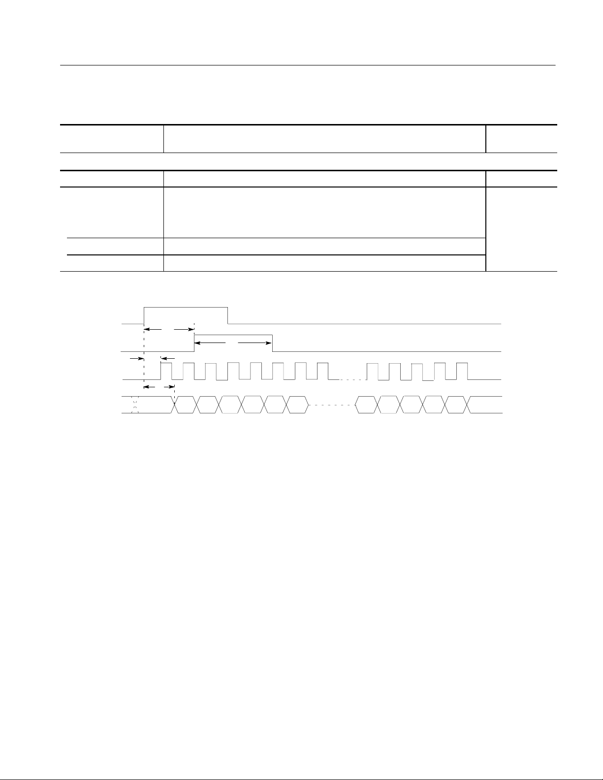
Table 1 -1: Warranted electrical characteristics (Cont.)
Performance Characteristics
Characteristics Performance
Description
T est
AC line power
Rating voltage 100 to 240 V AC
Voltage range
90 μ 250 V AC 48.0 to 63.0 Hz
90 μ 127 V AC 48.0 to 440 Hz
Maximum power 300 W
Maximum current 4A
External
Trigger
Sync Out
Clock Out
Data Out
T
d1
T
w1
T
d2
T
d3
D
0
D
1
D
D
3
2
D
0
D
n
Figure 1-1: Trigger delay
DG2020A Service Manual
1-7
Page 26

Performance Characteristics
Table 1-2: Warranted environmental characteristics
Characteristics Description
Temperature
Operating +10 _Cto+40_C
Non operating -- 2 0 _Cto+60_C
Relative humidity
Operating 20% to 80% (No condensation)
Maximum wet-bulb temperature 29.4 _C
Non operating 5% to 90% (No condensation)
Maximum wet-bulb temperature 40.0 _C
Altitude
Operating To 4.5 km (15,000 feet).
Maximum operating temperature decreases 1_C each 300 m above
1.5 km.
Non operating To 15 km (50,000 feet).
Dynamics
Vibration
Operating 0.33 mm
Shock
Non operating 294 m/s2(30 G), half-sine, 11 ms duration.
Installation requirements
Power consumption
(Fully loaded)
Surge current 30 A peak for < 5 line cycles, after product has been off for at least 30 s.
Cooling clearance
Top clearance 1 inch
Side clearance 6 inches
Rear clearance 3 inches
300 watts max. Maximum line current is 4 A rms at 50 Hz, 90 V line.
, 10 to 55 Hz, 15 minutes
p-p
1-8
DG2020A Service Manual
Page 27

Typical Characteristics
This section will describe the typical characteristics for the DG2020A. These
values represent typical or average performance and are not absolutely guaranteed.
Table 1 -3: Electrical characteristics (typical)
Characteristics Description
Clock generator
Internal clock
Period jitter Measured by TDS694C--1MHD with TDSJIT1
RefertoTable1-4.
Cycle to cycle jitter Measured by TDS694C--1MHD with TDSJIT1
RefertoTable1-5.
P3410 ( TTL output pod )
Performance Characteristics
Data output
Over / under shoot < 0.5V(into1MΩ 10 pF )
Rise / fall time 2 ns ( 20% to 80%, into 1 MΩ 10 pF )
Channel skew < 3 ns ( CH0 and other channels, same pod )
< 2 ns ( CH0 and CH0, two pods of same type )
Internal inhibit delay -- 5 n s
Inhibit input
Delay to data output 18 ns
P3420 ( Variable output pod )
Data output
Output current Total output current < 500 mA
< --30 mA ( Sink )
> +30 mA ( Source )
Over / under shoot < ¦(5%ofSwing)¦ 0.1V(into1MΩ 10 pF )
Rise / fall time 2 ns ( 20% to 80%, into 1 MΩ 10pF,0to5Vswing)
Channel skew < 3 ns ( CH0 and other channels, same pod )
< 2 ns ( CH0 and CH0, two pods of same type )
Internal inhibit delay -- 2 n s
Inhibit input
Delay to data output 16 ns
DG2020A Service Manual
1-9
Page 28
Performance Characteristics
Table 1 -3: Electrical characteristics (typical) (Cont.)
Characteristics Description
P3420 ( Variable output pod )
Period jitter Measured by TDS694C--1MHD with TDSJIT1
RefertoTable1-4.
Cycle to cycle jitter Measured by TDS694C--1MHD with TDSJIT1
RefertoTable1-5.
Auxiliary outputs
Sync output
Duration 6 clocks ( Tw1in Figure 1-1 )
Clock output
Delay to data output 24 ns ( P3410 )
20 ns ( P3420 )
Auxiliary inputs
External clock input
Delay to P3410 data output 36 ns
Delay to P3420 data output 33 ns
Table 1-4: Period JItter
Clock frequency 200 MHz (When PLL to On.) 100 MHz (When PLL to On.)
Measurement StdDev Pk--Pk StdDev Pk--Pk
Clock output 13.0 ps 70.0 ps 10.0 ps 60.0 ps
Data output (CH0 output) 6.0 ps 35.0 ps 5.5 ps 34.0 ps
Table 1 -5: Cycle to Cycle JItter
Clock frequency 200 MHz (When PLL to On.) 100 MHz (When PLL to On.)
Measurement StdDev Pk--Pk StdDev Pk--Pk
Clock output 20.0 ps 115.0 ps 17.0 ps 110.0 ps
Data output (CH0 output) 9.0 ps 52.0 ps 8.5 ps 50.0 ps
1-10
DG2020A Service Manual
Page 29

Nominal Traits
This section describes general characteristics of the DG2020A. These can be
divided into two main categories: electrical characteristics and mechanical
characteristics.
Table 1 -6: Nominal traits - electrical characteristics
Characteristics Description
Output pattern
Pattern length 64 word to 64 K word ( non sequenced operation )
64 word to unlimited ( sequenced operation )
Number of channels Up to 12, 24 ( Option 01 ), 36 ( Option 02 )
Memory capacity
Pattern memory 64 K word ¢ 12 bits
64 K word ¢ 24 bits ( Option 01 )
Performance Characteristics
64 K word ¢ 36 bits ( Option 02 )
Sequence memory 2048 steps
NOTE: More than 2,048 lines can be input in the Sequence table. However, only first 2,048
steps expanded in the sequence memory are effective when executed.
NV RAM 0.5 M bytes
Clock generator
Internal clock
Frequency 0.1 Hz to 200 MHz
Resolution 4 digits
Reference oscillator
Frequency 10 MHz
P3410 ( TTL output pod )
Data output
Impedance 50 Ω
Delay channel CH8, CH9, CH10 and CH11
Delay time 0to20ns
Delay resolution 0.1 ns
Event input
Level TTL
Impedance 1 kΩ
Setup time to next block 47 clock to 54 clock
DG2020A Service Manual
1-11
Page 30

Performance Characteristics
Table 1 -6: Nominal traits - electrical characteristics (Cont.)
Characteristics Description
P3410 ( TTL output pod )
Inhibit input
Level TTL
Impedance 1 kΩ
P3420 ( Variable output pod )
Data output
Output impedance 50 Ω
Output voltage
V
OH
V
OL
--2.0Vto+7.0Vinto1MΩ
--3.0Vto+6.0Vinto1MΩ
Resolution 0.1 V
Maximum swing 9.0 V
Minimum swing 0.5 V
p-p
p-p
Delay channel CH8, CH9, CH10 and CH11
Delay time 0to20ns
Delay resolution 0.1 ns
Event input
Threshold
Level --5.0 V to +5.0 V
Resolution 0.1 V
Impedance 1 kΩ
Setup time to next block 47 clock to 54 clock
Inhibit input
Threshold
Level --5.0 V to +5.0 V
Resolution 0.1 V
Impedance 1 kΩ
1-12
DG2020A Service Manual
Page 31

Table 1 -6: Nominal traits - electrical characteristics (Cont.)
Characteristics Description
Auxiliary outputs
SYNC output
Level Positive TTL pulse
Performance Characteristics
2.4 V < V
0V<V
< 5.0 V ( into 1 MΩ )
OH
< 0.5 V ( into 1 MΩ )
OL
Output resistance 50 Ω
Connector BNC ( at front panel )
EVENT output
Level Positive TTL pulse
2.4 V < V
0V<V
< 5.0 V ( into 1 MΩ )
OH
< 0.5 V ( into 1 MΩ )
OL
Delay time 22 clocks before Data Output change
Duration 8 clocks
Output resistance 50 Ω
Connector BNC ( at front panel )
CLOCK output
Output resistance 50 Ω
Connector SMB ( at rear panel )
Auxiliary inputs
TRIGGER input
Threshold
Level --5.0 V to +5.0 V
Resolution 0.1 V
Impedance 1kΩ or 50 Ω ( selectable )
Connector BNC ( at front panel )
Data output delay uncertainty Clock Setting Delay Uncertainty
Internal Clock, PLL:ON
Internal Clock, PLL:OFF
External Clock
5nsto10ns
None
1 clock period
External clock input
Impedance 50 Ω, terminated to +0.5 V
Connector SMB ( at rear panel )
DG2020A Service Manual
1-13
Page 32

Performance Characteristics
Table 1 -6: Nominal traits - electrical characteristics (Cont.)
Characteristics Description
Display
Display area 5.2 inches ( width ) ¢ 3.9 inches ( height )
Resolution 640 ( H ) ¢ 480 ( V ) pixels
Power source
AC line power
Fuse Rating 6A FAST, 250 V, UL 198G ( 3AG )
5A ( T ), 250 V, IEC 127
Battery
Type Li3 V, 650 mAH
1-14
DG2020A Service Manual
Page 33

Table 1 -7: Nominal traits - m echanical characteristics
Characteristics Description
DG2020A
Net weight
Standard 9.7 kg
Dimensions
Height 6.4 inches including feet
Width 14.3 inches including handle
Length 19.25 inches including front cover
22.2 inches with handle extended
P3410 ( TTL output pod )
Net weight 0.5 kg ( excluding cables )
Dimensions
Height 2.0 inches including feet
Performance Characteristics
Width 5.9 inches
Length 4.0 inches
P3420 ( Variable output pod )
Net weight 1.0 kg ( excluding cables )
Dimensions
Height 2.0 inches including feet
Width 10.0 inches
Length 6.3 inches
Pod cable
Length 1.2 m
DG2020A Service Manual
1-15
Page 34

Performance Characteristics
Certification and Compliances
The certification and compliances for the DG2020A are listed in Table 1-8.
Table 1-8: Certifications and compliances
Category St andards or description
EC Declaration of Conformity -EMC
Australian/New Zealand
declaration of Conformity - EMC
EC Declaration of Conformity -Low Voltage
Approvals Complies with the following safety standards:
Installation Category Description Terminals on this product may have different installation (over--voltage) category designations. The
Meets intent of Directive 89/336/EEC for Electromagnetic Compatibility. Compliance was
demonstrated to the following specifications as listed in the Official Journal of the European
Communities:
EMC Directive 89/336/EEC:
EN 55011 Class A Radiated and Conducted Emissions
EN 50081-1 Emissions:
EN61000-3-2 AC Power Line Harmonic Emissions
EN 50082-1 Immunity:
EN61000-4-2 Electrostatic Discharge Immunity
EN61000-4-3 RF Electromagnetic Field Immunity
EN61000-4-4 Electrical Fast Transient/Burst Immunity
EN61000-4-6 Conducted Disturbance Induced by Radio--frequency Field
EN61000-4-8 Power Frequency Electromagnetic Field Immunity
EN61000-4-11 Voltage Dips and Interruptions Immunity
Complies with EMC provision of Radio--communications Act per the following standard:
AS/NZS 2064.1/2 Industrial, Scientific, and Medical Equipment: 1992
Compliance was demonstrated to the following specification as listed in the Official Journal of the
European Communities:
Low Voltage Directive 73/23/EEC, amended by 93/68/EEC
EN 61010-1/A1:1992 Safety requirements for electrical equipment for
measurement, control and laboratory use.
UL3 111 --11, First Edition Standard for electrical measuring and test equipment.
CAN/CSA C22.2 No.1010.1-921Safety requirements for electrical equipment for
measurement, control and laboratory use.
installation categories are:
Category Examples of products in this category
CAT III Distribution-level mains (usually permanently connected). Equipment at this
level is typically in a fixed industrial location.
CAT II Local-level mains (wall sockets). Equipment at this level includes appliances,
portable tools, and similar products. Equipment is usually cord-connected.
CAT I Secondary (signal level) or battery operated circuits of electronic equipment.
1-16
DG2020A Service Manual
Page 35

Performance Characteristics
Table 1-8: Certifications and compliances (cont.)
Category Standards or description
Pollution Degree A measure of the contaminates that could occur in the environment around and within a product.
Typically the internal environment inside a product is considered to be the same as the external.
Products should be used only in the environment for which they are rated.
Pollution Degree 2 Normally only dry , nonconductive pollution occurs. Occasionally a
temporary conductivity that is caused by condensation must be
expected. This location is a typical office/home environment.
Temporary condensation occurs only when the product is out of
service.
Conditions of Approval Safety Certifications/Compliances are made for the following conditions:
Altitude (maximum operation): 2000 meters
IEC Characteristics Equipment type:
Test and Measuring
Installation Category II (as defined in IEC 61010--1, Annex J)
Pollution Degree 2 (as defined in IEC 61010--1)
Safety Class I (as defined in IEC 61010--1, Annex H)
1
CSA-C22.2 No.1010.1, UL3111-1, IEC61010-1 Safety Certification Compliance:
Altitude (maximum operating): 2000 meters
DG2020A Service Manual
1-17
Page 36

Performance Characteristics
1-18
DG2020A Service Manual
Page 37

Preparation for Use
This section describes how to prepare the DG2020A Data Generator for use. The
information describes these items:
H Proper operating environment
H Checking power cord and line voltage configurations
H Checking the fuse
H Power-on and power-off cycles
Supplying Power
Before installing the DG2020A, note these precautions:
WARNING. To avoid equipment failure and potential fire or personal shock
hazards, do not exceed the maximum rated operating voltage of 250 V between
the voltage-to-ground (earth) and either pole of the power source. The DG2020A
operates from a single-phase power source and has a three-wire power cord with
a two-pole, three-terminal grounding plug. Also, before making connection to the
power source, be sure the DG2020A has a suitable two-pole, three-terminal
grounding-type plug.
DG2020A Service Manual
To avoid personal shock hazard, do not contact conductive parts. All accessible
conductive parts are directly connected through the grounding conductor of the
power cord to the grounded (earthing) contact of the power plug. The DG2020A
is safety Class 1 equipment (IEC designation).
To avoid personal shock hazard, do not defeat the grounding connection. Insert
the power input plug only in a mating receptacle with a grounding contact where
earth ground has been verified by a qualified service person. Also, for electrical
shock protection, make the grounding connection before making connection to
the DG2020A input or output terminals.
2-1
Page 38

Preparation for Use
Power Cord Information
The DG2020A ships with the required power cord as ordered by the customer.
Table 2-1 gives the color-coding of the conductors in the power cord. Table 2-2
shows information on the available power cords.
Table 2-1: Power-cord conductor identification
Conductor Color Alternate color
Ungrounded (Line) Brown Black
Grounded (Neutral) Light Blue White
Grounded (Earthing) Green/Yellow Green
Table 2-2: Power cord identification
Plug configuration Normal usage Option number
North America
125 V
Europe
230 V
United Kingdom
230 V
Australia
230 V
North America
230 V
Switzerland
230 V
Standard
A1
A2
A3
A4
A5
2-2
DG2020A Service Manual
Page 39

Operating Environment
Preparation for Use
To ensure proper DG2020A operation and long life, note the following environmental requirements.
Operating Temperature
Ventilation Requirements
The DG2020A operates in an environment with an ambient air temperature
between +10_ C and +40_ C. The DG2020A storage temperature ranges from
-- 2 0 _ Cto+60_ C. After storage at temperatures outside the operating limits,
allow the DG2020A chassis to stabilize at a safe operating temperature before
applying power.
Air drawn in and exhausted through the cabinet side and bottom panels cools
DG2020A internal circuits. To ensure proper cooling, allow the following
clearances:
Top 2.5 cm (1 in.)
Back 7.5 cm (3 in.)
Left and right 15 cm (6 in.)
The feet on the bottom of the DG2020A cabinet provide the required clearance
when it is set on a flat surface. The top of the DG2020A does not require
ventilation clearance.
CAUTION. To prevent temporary shutdown of the DG2020A, do not restrict air
flow through the chassis. If the DG2020A shuts down unexpectedly, improve
ventilation around the DG2020A and wait a few minutes to allow it to cool
down; then switch the power on again.
Rear Panel Controls
DG2020A Service Manual
Section 1, Specifications, lists the line voltage and frequency ranges over which
the DG2020A operates.
Figure 2-1 shows the rear panel controls for the DG2020A.
2-3
Page 40

Preparation for Use
Power Connector
Fuse Type and Rating
WARNING
Fuse
ATTENTION
!
!
PRINCIPAL POWER SWITCH
Figure 2-1: Rear panel controls
The DG2020A uses the same fuse for all operating line voltage ranges. One of
two fuse types is installed in the instrument, depending upon the power cord
option. Table 2-3 provides the available types and ratings.
Table 2-3: Fuse type and rating
Power cord option Fuse Fuse part number Fuse cap part number
Standard, Option A4 0.25 inch × 1.25 inch
159-0239-00 200-2264-00
(UL 198G,3AG):6A FAST,250V
Option A1, A2, A3, A5 5mm× 20 mm (IEC 127): 5A(T),250V 159-0210-00 200-2265-00
WARNING. To avoid electrical shock, always unplug the power cord from the
socket before checking the line fuse.
To check the fuse, remove the fuse holder on the rear panel. Refer to Figure 2-1
for the location of the fuse holder. To remove the fuse holder, turn it counterclockwise with a screwdriver while pushing it in. Then remove the fuse from the
fuse holder.
2-4
DG2020A Service Manual
Page 41

Applying and Interrupting Power
Consider the following information when you power on or power off the
DG2020A, or when external power loss occurs.
CAUTION. When connecting the DG2020A to a pod with a pod connection cable,
turn off the DG2020A power before connecting the cable. Connecting the cable
with the power in the on state can damage the DG2020A and the pod.
Preparation for Use
Power-on Cycle
Power-off Cycle
Memory Backup Power
At power-on, the start-up diagnostics check the DG2020A operation. If all
diagnostic items complete without error, the DG2020A displays the EDIT menu.
If the diagnostics detect an error, the DG2020A displays the error code. To exit
the diagnostics menu, press any key; then the system displays the EDIT menu.
See section 6, Maintenance, for information on diagnostics and fault isolation.
NOTE. If the ambient temperature goes outside the specified operating tempera-
ture range, an error occurs during the diagnostics at power-on. If this happens,
power off the DG2020A and wait until the chassis temperature is appropriate;
then switch the power on again.
Wait for the DG2020A to finish the operation when saving data files. Improper
power-off or unexpected loss of power to the DG2020A can result in the
corruption of data stored in nonvolatile memory.
A lithium battery maintains internal nonvolatile memory, allowing the DG2020A
to retain data files if AC power is lost. This battery has a shelf life of about three
years. Partial or total loss of stored information at power-on may indicate that the
battery needs to be replaced.
DG2020A Service Manual
WARNING. To avoid risk of fire or explosion, replace the DG2020A battery with a
lithium battery having the part number listed in section 10, Mechanical Parts
List. This battery is a safety-controlled part.
To avoid risk of fire or explosion, do not recharge, rapidly discharge, or
disassemble the battery; and do not incinerate the battery or heat it above
100° C. Also, dispose of used batteries promptly. Small quantities of used
batteries can be disposed of in normal refuse. Keep lithium batteries away from
children.
2-5
Page 42

Preparation for Use
Repackaging Instructions
Use a corrugated cardboard shipping carton having a test strength of at least
275 pounds and with an inside dimension at least six inches greater than the
DG2020A dimensions. (If available, use the original shipping carton, which
meets these requirements.)
If the DG2020A is shipped to a Tektronix Service Center, enclose the following
information:
H The owner’ s address
H Name and phone number of a contact person
H Type and serial number of the DG2020A
H Reason for returning
H A complete description of the service required
Seal the shipping carton with an industrial stapler or strapping tape.
Installed Options
Mark the address of the Tektronix Service Center and your own return address on
the shipping carton in two prominent locations.
Your DG2020A may include one or more options. To determine which options
are installed, look at the instrument option configuration listed on the rear panel.
Table 2-2 on page 2-2 gives information about line cord options. Section 7,
Options, lists other options and optional accessories. For further information and
prices of options, see your Tektronix Products catalog or contact a Tektronix
Field Office.
2-6
DG2020A Service Manual
Page 43

Operating Instructions
Before servicing the DG2020A, read the following operating instructions. These
instructions are at the level appropriate for s ervicing the DG2020A. The user
manual contains complete operator instructions.
In addition, Section 4, Performance Verification, includes instructions for
making the front-panel settings required to check DG2020A characteristics.
How to Make Connection to Pods
Connect the DG2020A connector to the pod using a pod connection cable as
shown in Figure 2-2 while paying attention to following points:
DG2020A (Rear)
P3410 or P3420 Pod (Rear)
DG2020A Service Manual
Pod Connection Cable
Figure 2-2: Pod connection
Note that the connectors on the DG2020A rear panel are installed with the tab
slot down, and the connector on the pod rear panel is installed with the tab slot
up (see Figure 2-3).
To connect a cable between the DG2020A and a pod, align the yellow wire end
of the cable connector with the triangular yellow index mark on the DG2020A or
pod connector. Doing this also correctly aligns the connector alignment tab. See
Figure 2-3. Then carefully but firmly insert the cable connector into the
DG2020A or pod connector.
2-7
Page 44

Operating Instructions
Pod Rear Panel
Tab S lot
Yellow Index
Mark
Yellow Index
Mark
To connect a cable between the DG2020A and a pod, align
the yellow wire end of the cable connector with the triangular
yellow index mark on the DG2020A or pod connector. Doing
this also correctly aligns the connector alignment tab. Then
carefully but firmly insert the cable connector into the
DG2020A or pod connector.
Tab
DG2020A Rear Panel
Yellow Wire
Cable
Tab S lots
Figure 2-3: Yellow index mark and yellow wire for cable connection
CAUTION. Turn off the instrument before connecting it to the pod. Connecting the
instrument to the pod with the power on could damage the instrument itself and
the pod. When attaching the pod cable, ensure that the plug and socket are
aligned correctly.
Make sure that you have correctly inserted the cable plug in the DG2020A and
the pod before turning on power. The yellow wire end of the connector must be
aligned with the triangular yellow index mark on the DG2020A or pod.
Incorrectly connected cables will damage the DG2020A and the pod.
The cable and the pod are coupled very tightly. Hold the connector housing to
avoid stress applied to the cable when attaching or removing the cable.
Electrostatic discharge can permanently damage the delicate ICs used in the
pod. Do not touch connector pins with bare hands, and do not bring conductive
materials, other than the DG2020A connection cable, close to the pod.
2-8
DG2020A Service Manual
Page 45

How to Power On
Operating Instructions
To power-on the DG2020A, follow these steps:
1. Set the PRINCIPAL POWER SWITCH (on the back of the DG2020A) to
the ON position. This switch is the main power switch; it routes power to the
standby circuit in the DG2020A.
2. Then, press the ON/STBY (standby) switch on the front (lower-left corner)
of the DG2020A. This switch applies power to the remaining circuits of the
DG2020A. Allow at least 20 minutes for the DG2020A to warm up.
WARNING. To avoid personal shock hazard, turn off both the ON/STBY sw itch
and the PRINCIPAL POWER SWITCH before servicing. The PRINCIPAL
POWER SWITCH on the rear panel is the true power disconnect switch. The
ON/STBY (standby) switch simply toggles operation on and off. When connected
to a power source and when the PRINCIPAL POWER SWITCH is on, the
internal power supplies and much of the other circuitry of the DG2020A remain
energized regardless of the setting of the ON/STBY switch.
To avoid personal shock hazard, set the PRINCIPAL POWER SWITCH off before
connecting or disconnecting the line cord to or from the power source.
Internal Diagnostics Routines
At power-on, the DG2020A performs internal start-up diagnostics. These
diagnostics check internal circuit function and report any failures. In addition,
you can initiate internal diagnostics using the Diag item in the UTILITY menu;
these diagnostics differ from the start-up diagnostics in that they do more
extensive memory checking.
User Interface
The DG2020A uses a combination of front-panel buttons, keys, a knob, and
on-screen menus to control generator functions. Some front-panel controls select
Menus and manipulate menu items. Others enter values and units, allow manual
triggering, start/stop DG2020A output, advance the pattern data, generate an
event pulse, and make a hard copy. On-screen graphics show various aspects of
the current DG2020A configuration.
DG2020A Service Manual
On-screen menus set most DG2020A functions. Main menus provide access to
lower-level nested submenus. Buttons in the center of the front panel select the
main menus.
2-9
Page 46

Operating Instructions
When you select a menu, the display shows t he items controlled by that menu
and numeric values currently in effect. Buttons around the display select
lower-level menus, change menu selections, modify numeric values and units,
and execute functions.
2-10
DG2020A Service Manual
Page 47

Operating Instructions
Display
1 2
6
3
5
4
7
8
Figure 2-4: CRT display
DG2020A Service Manual
2-11
Page 48

Operating Instructions
Table 2-4: DG2030 display elements
Figure
number
1 Status area Displays the current status of the instrument. This status line is
2 Date and Time
3 Side menu Related side menu items are displayed here when a bottom menu
Label
display area
Description
page
always displayed, whichever menu is displayed. The status line
displays the following four items.
MODE: Displays the run mode in which pattern data will be
output.
UPDATE: Displays the update method for pattern data output
when data is updated.
PLL: Displays whether or not the PLL circuit is used as the internal
oscillator circuit.
POD: Displays the configuration of pods attached to the
instrument.
In addition, there is also a disk icon that indicates whether or not a
floppy disk is inserted in the disk drive. A clock icon may also be
displayed at the left end of the status line. When this icon is
displayed, the instrument is busy with internal processing and
cannot accept other inputs.
The date and time display can be turned on or off using the
UTILITY menu.
item is selected. The topmost entry in the side menu displays
either a label representing the side menu or the operation name
for the confirmed item.
4 Bottom menu When one of the buttons in the menu section is pressed, the
corresponding bottom menu is displayed. When a bottom menu
item is selected the corresponding side menu is displayed.
Selecting the same bottom menu item again closes the side
menu.
5 Button function
description
area
6 Message dis-
play area
7 Popup mes-
sage box
8 Popup menu The instrument sometimes displays a pop-up menu when a
Displays descriptions of the functions of the front panel buttons.
Displays messages that report on the current processing state.
This area can be also used by remote commands to display user
messages.
When required, the instrument temporarily displays a window at
the center of the screen to display a warning or question for the
user.
bottom menu or side menu item is selected. Enter a numeric value
or select an item using either the general purpose knob or the
front panel buttons.
2-12
DG2020A Service Manual
Page 49

Menus
Operating Instructions
The DG2020A operation is primarily controlled by means of menus that
correspond to the SETUP, EDIT, APPLICATION and UTILITY buttons in
the MENU column. To display one of these main menus on the screen, push the
corresponding button. The button LED indicates which menu i s currently
selected. Refer to the User Manual for more details concerning these menus.
H EDIT Menu
Provides functions for editing pattern data and creating sequences.
H SETUP Menu
Provides functions for defining groups, setting up channels, and setting pod
voltages, the operating mode, and triggers.
H APPLICATION Menu
Although the current version of the firmware does not provide any functions
under the APPLICATION menu, Tektronix plans to provide functions that
support various application areas under this menu in future upgrades to the
firmware.
Pattern Storage and I/O
H UTILITY Menu
This menu provides functions for manipulating the basic instrument settings.
The DG2020A has internal nonvolatile memory (NVRAM) for pattern file
storage. The DG2020A generates patterns from file residing in internal nonvolatile memory.
The DG2020A also has a floppy-disk drive for loading files from floppy disk
into internal nonvolatile memory, and for saving files from memory to floppy
disk. The disk drive accepts 3.5-inch floppy disks in the MS-DOS format.
DG2020A Service Manual
2-13
Page 50

Operating Instructions
Loading Files
The following steps explain how to load files from a floppy disk into internal
memory.
1. Turn the disk so the side with the arrow is on top; insert the disk into the
DG2020A floppy disk drive.
2. Push the EDIT button in the MENU column.
3. Select File from the bottom menu.
4. Select Load Data & Setup from the side menu. The menu in Figure 2-5
appears.
5. Turn the general purpose knob to highlight the file you want to load and
select OK from the sub menu.
6. Push the floppy drive button and remove the disk from the floppy drive.
2-14
Figure 2-5: Load data & setup menu
DG2020A Service Manual
Page 51

Signal Output
Operating Instructions
The procedure assumes that data has already been loaded as explained in the
previous section.
The following example first groups the data bits from the pattern data already
created and allocates each data bit to pod pins. Next, this procedure sets all the
settings required for signal output and actually outputs the signals.
H Tables such as the one below show in the operating procedure. Execute the
action in left end of the top row first. Then execute actions from left to right
along the row. When one row has been completed, move to the left end of
the next row down, and repeat. For pop up menus, use the general purpose
knob to select items from the menu list. Operations such as operation 6
(below) do not involve pressing the buttons shown in the row above, but
rather are descriptions of operations to be performed. Figure 2-6 shows the
buttons used and the menu layout.
Front panel
Menu button Bottom button Popup menu Side button
Operation 1 Operation 2 Operation 3 Operation 4 Operation 5
button
Operation 6 (For example, set to xx with general purpose knob.)
Operation 7
Popup Menu
Bottom Menu
Side Menu
Bottom Button
General Purpose Knob
Side Button
Figure 2-6: Operating buttons and menu layout
Front Panel Button
Menu Button
DG2020A Service Manual
2-15
Page 52

Operating Instructions
Grouping the dat a bits
1. Assign DATA00 to DATA03 to a group called IC1.
a. Reset all bit allocations.
Menu button Bottom button Popup menu Side button
SETUP Group Assign Reset All bits
Assign
OK
b. Set the MSB and LSB to D03 and D00, respectively.
Menu button Bottom button Popup menu Side button
Select
32 DATA03.
Group Bit(s)
Config
Front panel
button
Front panel
button
MSB
(Set D03.)
LSB
(Set D00.)
OK
NOTE. The MSB setting may change depending on the direction the general
purpose knob is turned. If that happens, the MSB setting must be set again.
c. Attach the name IC1 to the newly created group.
Front panel
Menu button Bottom button Popup menu Side button
Rename
Clear String
I, C, 1 OK
button
2. Assign DATA04 to DATA07 to a group called IC2.
2-16
a. Set the MSB and LSB.
DG2020A Service Manual
Page 53

Operating Instructions
Front panel
Menu button Bottom button Popup menu Side button
Select
28 DATA07.
NOTE. The MSB setting may change depending on the direction the general
Group Bit(s)
Config
MSB
(Set D07.)
LSB
(Set D04.)
OK
button
purpose knob is turned. If that happens, the MSB setting must be set again.
b. Attach the name IC2 to the group.
Allocating Data Bits to the
Pod Channels
Front panel
Menu button Bottom button Popup menu Side button
Rename
Clear String
I, C, 2 OK
button
3. Allocate data bits to pod channels A-00 to A-11.
a. Clear the pod channel for channels A-00 to A-03.
Front panel
Menu button Bottom button Popup menu Side button
Pod Assign
Press the front panel up arrow button to select channel A-00 from the POD assign list.
Release
Clear the A-01 to A-03 allocations in the same manner.
button
DG2020A Service Manual
b. Allocate the IC1 group data to the pod channels A-04 to A-07 and turn
off the output impedance control for each channel.
2-17
Page 54

Operating Instructions
Front panel
Menu button Bottom button Popup menu Side button
Press the front panel down arrow button to select channel A-04 from the POD assign
list.
Select data D03 (IC1:03) from the Data bits list using the general purpose knob.
Assign
Change Inhibit
Control
Select OFF. OK
Allocate D02 to D00 to A-05 to A-07 using the same procedure and turn off the output
impedance control for each channel.
OK
NOTE.PresstheOK button when done to activate the allocations. Note that the
button
allocations will not become valid unless the OK button is pressed.
c. Allocate the IC2 group data to the pod channels A-08 to A-11 and turn
off the output impedance control for each channel.
Front panel
Menu button Bottom button Popup menu Side button
Pod Assign
Press the front panel down arrow button to select channel A-08 from the POD assign
list.
Select data D07 (IC2:03) from the Data bits list using the general purpose knob.
Assign
Change Inhibit
Control
Select OFF. OK
Allocate D06 to D04 to A-09 to A-11 using the same procedure and turn off the output
impedance control for each channel.
OK
NOTE.PresstheOK button when done to activate the allocations. Note that the
button
allocations will not become valid unless the OK button is pressed.
2-18
DG2020A Service Manual
Page 55

Operating Instructions
To summarize, the above has allocated data bits to the pods as shown in Figure
2-7.
POD assign
Channel Name Data Inhibit
Setting the Sampling
Clock Frequency
A-00
Allocations cleared
Data bits D03 to
D00 allocated
Data bits D07 to
D04 allocated
A-01
A-02
A-03
A-04
A-05
A-06
A-07
A-08
A-09
A-10
A-11
Pod Channel
IC1:03
IC1:02
IC1:01
IC1:00
IC2:03
IC2:02
IC2:01
IC2:00
Group Name Data bit
D03
D02
D01
D00
D07
D06
D05
D04 OFF
Figure 2-7: Pod channel data bit allocation
4. Setthesamplingclockfrequencyto50MHz.
--- --- ---
--- --- ---
--- --- ---
--- --- --OFF
OFF
OFF
OFF
OFF
OFF
OFF
Output Impedance Control
DG2020A Service Manual
Menu button Bottom button Popup menu Side button
Oscillator Source
(Select Int.)
Int Frequency 5, 0, MHz
PLL
(Select On.)
Front panel
button
2-19
Page 56

Operating Instructions
Setting the Signal
Generation Mode
5. Set the signal generation mode to continuous mode.
Setting the Pod Output
Level ( P3420 Only)
Menu button
Bottom button
Run Mode Repeat
Popup menu Side button
Front panel
button
There are two pod models that can be used with the DG2020A. The P3410 pod
output level is always at the TTL level. However, the P3420 pod output level is
variable. This step sets output levels for the P3420 pod.
6. Set the pod channel A-04 to A-11 output levels to 4V for the high level and
0V for the low level.
Front panel
Menu button Bottom button Popup menu Side button
Level/Delay
Select channel A-04 using the front panel up and down arrow buttons.
High Level 4, ENTER
Low Level 0, ENTER
Set the output levels for channels A-05 to A-11 in the same manner.
button
2-20
Setting the Pod
Delay Time
The delay time for channels A-08 to A-11 is variable in both the P3410 and the
P3420 pod.
7. Set the delays for the pod channels A-08 to A-11 to5ns.
Front panel
Menu button Bottom button Popup menu Side button
Level/Delay
Select channel A-08 using the front panel up and down arrow buttons.
Delay 5, ENTER
Set the delays for channels A-09 to A-11 in the same manner.
button
DG2020A Service Manual
Page 57

Operating Instructions
Output Voltage
Level Setting
Delay Time Setting
Figure 2-8: Output voltage level and delay time display for the P3420 pod
Signal Output
This step actually outputs the signals.
8. Press the START/STOP button on the front panel.
DG2020A Service Manual
2-21
Page 58

Operating Instructions
2-22
DG2020A Service Manual
Page 59

Theory of Operation
This section describes the basic operation of the major circuit blocks or modules
in the DG2020A. Section 9, Diagrams, includes a block diagram and a interconnect diagram. Figures 9-1 shows the modules and functional blocks of the
DG2020A with Options 01 and 02 installed. Figure 9-2 shows how the modules
interconnect.
Module Overview
The module overview describes the basic operation of each functional circuit
block.
The DG2020A Data Generator is a portable instrument with 12 to 36 channel
output. The DG2020A reads out the digital pattern data loaded into its pattern
data memory. The point rate clock determines the rate at which data is read out.
The DG2020A outputs the pattern data at this rate.
Clock Generator (A30
Clock Board)
Trigger Circuit (A30, Clock
Board)
Sequence Memory (A50,
PG Master Board)
Pattern Data Memory
(A50, PG Master Board
and A51, PG Slave Board)
The clock generator is made up of a blocking oscillator that operates between
100 MHz and 200 MHz, a 10 MHz reference oscillator, and a dividing circuit.
The blocking oscillator is combined with the 10 MHz reference oscillator to
form a phase lock loop (PLL) circuit. The PLL operation can also be prevented;
in such cases, oscillation begins as soon as an external trigger signal is received.
The output of the blocking oscillator is divided by the dividing circuit and
supplied to the A50 PG Master board and A51 PG Slave board as a point rate
clock signal ranging from 200 MHz to 0.1 Hz.
The trigger circuit corrects the external trigger signal, and sets the trigger level
and trigger slope. The output from this circuit controls the clock output from the
clock generator .
Stored in the sequence memory is a type of program that designates the sequence
and repetitions for t he output of pattern data. The contents of the sequence
memory are determined by the Make Sequence submenuintheEDIT menu.
The pattern data memory stores the pattern data output from the pod. Its contents
are read out in the order in which they were programmed in sequence memory,
and sent to the shift register.
Shift Register (A50, PG
Master Board and A51,
Slave Board)
DG2020A Service Manual
The shift register performs parallel/serial conversion for the data sent from t he
pattern data memory.
3-1
Page 60

Theory of Operation
Delay Circuit (A60, TTL
Pod Board and A65,
Variable Pod B oard)
Level Control (A65,
Variable Pod B oard)
CPU and Memory (A6,
CPU Board)
GPIB (A6, CPU Board)
Channels 08 through 11 in the TTL pod and variable pod are equipped with
delay circuits that can delay the pattern data from 0 ns to 20 ns.
The variable pod has a function for varying the high and low output levels. This
function is made possible by the DAC and the pin driver.
This functional block directs operation of all internal circuits, based on front
panel control operation and commands received over the GPIB or RS-232-C
interface. This circuit includes the 68000 CPU, DRAM, EPROM, and SRAM.
Data in memory is retained by a lithium battery on the A17 Backplane board.
CAUTION. To avoid l osing pattern data files stored in NVRam, save the files to a
floppy disk before removing the A6 CPU board or A17 Backplane board. Then
restore the files from floppy disk to DG2020A nonvolatile memory after
reinstalling the board(s).
This functional block is the General Purpose Interface Bus (GPIB) interface
driver, which controls communication with external devices over the parallel
interface. The GPIB connector is on the rear panel.
RS-232-C (A6, CPU Board)
Display Control (A6, CPU
Board)
Display Monitor
Front Panel (A 12,
Keyboard)
Floppy Disk Drive
This functional block is the RS-232-C interface circuit which controls serial
communication with external devices over the RS-232-C interface. The
RS-232-C interface connector is on the rear panel.
The display control block processes the test and pattern information based on
commands from the processor. The block sends the text and pattern information
to the display monitor as video signals, with vertical and horizontal sync control.
This display monitor takes in the video signals and displays t hem on a 17.8 cm
(7 in.) CRT screen. The display resolution is 480 × 640 pixels.
The front panel block includes the buttons, keys, and knobs for entering
selections. User selections from the front panel are sent to the processor. The
buttons at the bottom and side of the display are also included in this block.
Commands from the processor control an LED in the buttons.
The 3.5-inch floppy disk drive supports both 2DD and 2HD MS-DOS formats.
3-2
DG2020A Service Manual
Page 61

Theory of Operation
Low Voltage Power Supply
(A4 Power Board)
Fan
Options
This functional block is a switching-type power supply that converts the line
voltage into the voltages required for internal circuit operation. The Power board
(A4) is also part of this block; it generates t he voltage required for the analog
circuits.
The fan prevents heat build-up inside the cabinet. It pulls air into t he right
(floppy-disk) side of the DG2020A and exhausts it out the left side.
The following three options are available on the DG2020A:
H Option 01: 24-Channel Output
This option adds another 12 channels to allow the instrument to output a
total of 24 channels. This option allows 2 individual pods, pod A and pod B,
to be used at the same time.
H Option 02: 36-Channel Output
This option adds another 24 channels to allow the instrument to output a
total of 36 channels. This option allows 3 individual pods, pod A, pod B,
and pod C, to be used at the same time.
For more information about these and other options, see section 7, Options.
DG2020A Service Manual
3-3
Page 62

Theory of Operation
3-4
DG2020A Service Manual
Page 63

Performance Verification
Introduction
This section describes the operation t ests for the DG2020A data generator and
the P3410 and P3420 pods, and the procedures for those test. The operation tests
can be divided into two categories.
H Self Tests
The DG2020A incorporates a diagnostic system that performs comprehensive instrument testing. This system confirms that the DG2020A is operating
correctly. The self tests execute quickly and require no special equipment
during execution.
H Performance Te sts
There are 3 performance test groups.
Performance tests for the DG2020A plus pod combination
Performance tests for the P3410 pod
Performance tests for the P3420 pod
These tests confirm the operation of the items that are marked with an
asterisk (*) in the guaranteed items in the operating specifications listed in
Section 1, ”Specification”. The equipment listed in Table 4-2 is required to
perform these performance tests.
DG2020A Service Manual
4-1
Page 64

Performance Verification
Before Running the Operation Tests
Warm up
File Loading
A 20 minute warm up period is required prior to running the operation tests.
The performance check disk provided with the DG2020A includes the files listed
in Table 4-1. The specified file must be loaded into the DG2020A for each
operation test item. These files include pattern data and setup information.
Table 4-1: Performance check disk’s file list
File name Operation test Unit tested
TP1CLK.PDA Internal clock frequency DG2020A
TP2EXCLK.PDA External clock input DG2020A
TP3DPOUT.PDA Digital output DG2020A
TP4TRIG.PDA External trigger operation DG2020A
TP5EVENT.PDA Event operation
Event input and inhibit input
TP6DCTTL.PDA Output voltage level P3410
TP7DELAY.PDA Variable delay P3410, P3420
TP8DCH.PDA Output voltage level P3420
TP9DCL.PDA Output voltage level P3420
DG2020A,
P3410, P3420
Use the following procedure to load the file required by a performance test into
the instrument.
H Operation : File load
1. Insert the performance check disk into the DG2020A’s floppy disk drive.
2. Press EDIT button from the MENU buttons.
3. Select File from the bottom menu.
4. Select Load Data & Setup from the side menu.
5. Select the required file using the general purpose knob.
6. Select OK from the sub menu.
4-2
DG2020A Service Manual
Page 65

Performance Verification
Required Equipment
Table 4-2 lists the equipment required for the performance tests.
Table 4-2: Required equipment
Item No. Required precision Recommended equipment Unit tested
Frequency counter 1 Frequency range: 0.1 Hz to 200 MHz
Precision: 7 digits or higher
Digital multimeter 1
Performance check
disk
Oscilloscope 1 Bandwidth: 500 MHz or higher Tektronix TDS520, TDS540, or equiva-
Function generator 1 Amplitude: 4 V, offset: 2 V (50 Ω
Data generator 1 Tektronix DG2020A P3410, P3420
Pod 1 Tektronix P3410 or P3420 DG2020A
SMB-to-pin-header
cable
SMB-to-BNC cable 2 Impedance: 50 Ω
SMB-to-SMB cable 1 Impedance: 50 Ω
BNC cable 2 Impedance: 50 Ω
50 Ω termination 1 Impedance: 50 Ω Tektronix part no. 011-0049-01 DG2020A
N-to-BNC adapter 1 Tektronix part no. 103-0045-00 DG2020A
SMB-to-BNC
conversion adapter
BNC-dual-banana
adapter
1MΩ resistor 1 1% tolerance Tektronix part no. 321-0481-00 P3410, P3420
Pod connection cable 1 Tektronix part no. 174-3548-00
T-connector 1 Tektronix part no. 103-0030-00 DG2020A
1 Tektronix part no. 063-1899-XX
2 Impedance: 50Ω
2 Tektronix part no. 015-0671-00 DG2020A,
1 Tektronix part no. 103-0090-00 P3410, P3420
DC voltage range: ¦10 V
Precision: 0.01 V
termination), frequency: 1 MHz or
higher
Connector: SMB to pin header
Length: 20 inches
Connector: SMB to BNC
Length: 40 inches
Connector: SMB to SMB
Length: 40 inches
Connector: BNC
Length: 24 inches
ANRITSU MF 1603A DG2020A
Tektronix DM2510 P3410, P3420
DG2020A
(provided with the DG2020A)
lent
Tektronix AFG2020 DG2020A
Tektronix part no. 012-1503-00 DG2020A,
Tektronix part no. 012-1459-00 DG2020A,
Tektronix part no. 012-1458-00 DG2020A,
Tektronix part no. 012-1342-00 DG2020A
(provided with the DG2020A)
P3410, P3420
DG2020A
P3410, P3420
P3410
P3420
P3420
P3410
DG2020A
P3410, P3420
DG2020A Service Manual
4-3
Page 66

Performance Verification
Test Procedure Notes
The following conventions are used in this manual for describing the self tests
and performance tests.
H The test items are described in the following order.
H Characteristic tested
H Required equipment
H Connections
H Test procedure
H The test procedure is presented in order starting with step 1, and progresses
through the end of the procedure. Tables such as the one shown below appear
in these steps. For these steps, press the buttons in the order shown in the
table, either from left to right or from top to bottom, to select the required
menu item. For popup menus, use the general purpose knob to select items
from the menu list. Operations such as operation 6 do not involve pressing
the buttons shown in the row above, but rather are descriptions of operations
to be performed. Figure 4-1 shows the buttons used and the menu layout.
Front panel
Menu button Bottom button Popup menu Side button
Operation 1 Operation 2 Operation 3 Operation 4 Operation 5
Operation 6 (e.g., insert a disk in the disk drive.)
Operation 7
Popup Menu
Bottom Menu
Side Menu
Bottom Button
General Purpose Knob
Front Panel Button
Menu Button
Side Button
button
4-4
Figure 4-1: Operating buttons and menu layout
DG2020A Service Manual
Page 67

Self Tests
Performance Verification
Execute the DG2020A self tests and confirm that no errors occurred.
1. Press the required buttons in the following order. If All is selected as the
Typ e, all test items will be run.
Front panel
Menu button Bottom button Popup menu Side button
UTILITY Diag Type (Select All.)
Execute
button
2. Confirm that all items passed by checking the Status display area shown in
Figure 4-2.
Figure 4-2: Diagnostics menu
If Fail is displayed in the Status display area an error code will be displayed
in the Comment column. See Table 4-3 for the meanings of the error codes.
NOTE. Contact your Tektronix sales representative if an error occurs.
Table 4-3: Error Codes
Error code Error meaning Failed component
1XX CPU diagnostic error A6 CPU board
2XX Display diagnostic error A6 CPU board
3XX Front panel diagnostic error A12 keyboard
4XX Clock diagnostic/calibration error A30 Clock board
5XX Trigger diagnostic/calibration error A30 Clock board
6XX Sequence memory diagnostic error A50/A51 PG board
7XX Pattern memory diagnostic error A50/A51 PG board
DG2020A Service Manual
4-5
Page 68

Performance Verification
Performance Tests for the DG2020A/Pod Combination
The items in this performance test are for the DG2020A in combination with a
pod. Perform these test items in the following order.
H Internal clock frequency 4-6.....
H External clock input 4-8........
H Digital output 4-9.............
H External trigger operation 4-12....
H Event operation 4-14............
Internal Clock Frequency
This test confirms the frequency precision of the DG2020A internal clock.
With the PLL circuit on: Clock frequency ¦50 ppm
With the PLL circuit off: Clock frequency ¦3%
H Required Equipment
H Frequency counter
H SMB-to-BNC cable
H 50Ω termination
H N-to-BNC adapter
H Performance check disk
H Connections Connect the clock output from the DG2020A rear panel to the
frequency counter input (INPUT B) through the N-to-BNC adapter with the
SMB-to-BNC cable.
DG2020A rear panel
Frequency counter
4-6
Clock Output
N-to-BNC adapter
SMB-to-BNC Cable
Figure 4-3: Frequency measurement connections
DG2020A Service Manual
Page 69

Performance Verification
H Setup. Set the frequency counter to frequency measurement mode.
H Characteristics Confirmation Procedure
1. Load the TP1CLK.PDA test pattern file from the performance check disk.
When the file is loaded, the DG2020A clock frequency will be set t o 200
MHz internally and the PLL circuit will be turned on.
The following two steps check the clock frequency precision with the PLL
circuit on and the internal clock frequency set to 200 MHz
2. Press the START/STOP button on the front panel so that the button’s LED
indicator lights.
3. Set the counter trigger to an appropriate value and confirm that the counter
displays a frequency in the range 199.99 to 200.01 MHz.
The following five steps check the clock frequency precision with the PLL
circuit on and the internal clock frequency set to 200 kHz or 100.0 mHz.
4. Change the frequency counter input to INPUT A through the 50 Ω termina-
tion with the SMB-to-BNC cable.
5. Press the following buttons to set the DG2020A clock frequency to 200 kHz.
Front panel
Menu button Bottom button Popup menu Side button
SETUP Oscillator Int Frequency 2,0,0,kHz/ms/mV
button
6. Set the counter trigger to an appropriate value, and confirm that the counter
displays a frequency in the range 199.99 to 200.01 kHz.
7. Set the DG2020A clock frequency to 100 mHz.
8. Set the frequency counter to frequency measurement mode.
9. Set the counter trigger to an appropriate value, and confirm that the counter
displays a frequency in the range 99.995 to 100.005 mHz.
The following two steps check the clock frequency precision with the PLL
circuit off and the internal clock frequency set to 200 MHz, 200 kHz and 100.0
mHz.
10. Press the following buttons to turn the PLL circuit off.
DG2020A Service Manual
Menu button Bottom button Popup menu Side button
SETUP Oscillator PLL (Set to Off.)
Front panel
button
4-7
Page 70

Performance Verification
11. Set the internal clock frequency to 200 MHz, 200 kHz, and 100.0 mHz, and
confirm that the frequencies and periods measured by the frequency counter
fall within the ranges shown in Table 4-4.
Table 4-4: Internal clock frequency precision (PLL off)
Internal clock frequency (Int Frequency) Clock frequency range
200.0 MHz 194 MHz to 206 MHz
200.0 kHz 194 kHz to 206 kHz
100.0 mHz (10.0 s) 97 mHz to 103 mHz (9.709 s to 10.31 s)
External Clock Input
Function generator
This test confirms external clock input operation. Confirm that the clock signal is
output from the CLOCK OUT connector when a square wave signal with a
frequency of 1 MHz and an amplitude of 1 V (V
>0.7V,VIL< 0.3 V) is input
IH
as an external clock signal.
H Required Equipment
H Oscilloscope
H Function generator
H Two SMB-to-BNC cables
H Performance check disk
H Connections Connect the clock output from the DG2020A rear panel to the
oscilloscope CH1 i nput with an SMB-to-BNC cable. Connect the function
generator output to the DG2020A rear panel clock input with the other
SMB-to-BNC cable.
DG2020A rear panel
Oscilloscope
SMB-to-BNC Cable
Figure 4-4: External clock input connection
4-8
Clock Input
Clock Output
SMB-to-BNC Cable
DG2020A Service Manual
Page 71

H Setup
H Oscilloscope
Displayed channel CH1.
Vertical axis 500 mV/div.....
Horizontal axis 1 s/div...
Trigger mode Auto.....
Trigger level 500 mV.....
Input coupling DC....
Input impedance 50 Ω..
H Function generator
Waveform Square wave.......
Frequency 1 MHz.......
Amplitude 1 V (50 Ω termination).......
Offset 500 mV (50 Ω termination)..........
H Characteristics Confirmation Procedure
Performance Verification
Digital Output
1. Load the TP2EXCLK.PDA test pattern file from the performance check
disk.
2. Press the START/STOP button on the front panel so that the button’s LED
indicator lights.
3. Confirm that the clock pulse waveform can be observed on the oscilloscope.
This test confirms that pattern data is output from the pod data outputs (CH0
through CH11).
H Required Equipment
H Oscilloscope
H P3410 or P3420 pod
H Pod connection cable
H SMB-to-pin-header cable (when a P3410 pod is used)
H SMB to BNC adapter (when a P3410 pod is used)
H SMB-to-BNC cable (when a P3420 pod is used)
H Performance check disk
DG2020A Service Manual
H Connections Connect the DG2020A rear panel pattern data output-connector
(POD A) to the data input-connector on the rear panel of a P3410 or P3420
pod using a pod connection cable.
4-9
Page 72

Performance Verification
CAUTION. When connecting the DG2020A to a pod with a pod connection cable,
turn off the DG2020A power before connecting the cable. Connecting the cable
with the power in the on state can damage the DG2020A and the P3410 pod.
When attaching the pod cable, ensure that the plug and socket are aligned
correctly.
Make sure that you have correctly inserted the cable plug in the DG2020A and
the pod before turning on power. The yellow wire end of the connector must be
aligned with the triangular yellow index mark on the DG2020A or pod.
Incorrectly connected cables will damage the DG2020A and the pod.
For more details, refer to HowtoMakeConnectiontoPodson page 2-7.
Next, connect the pod CH0 signal output to the oscilloscope CH1 input
using an SMB-to-pin-header cable and an SMB to BNC adapter (for a P3410
pod) or an SMB-to-BNC cable (for a P3420 pod). See Figure 4-5 for the
general method of connection. Also, see Figures 4-6 and 4-7 for detailed
views of the pod data output connectors.
DG2020A rear panel
Pattern Data Output
Connector (POD A)
Figure 4-5: Pod connection
(Rear)
Pod Connection Cable
Oscilloscope
(Front)
Pod
SMB-to-pin-header Cable and
SMB-to-BNC Adapter (P3410)
SMB-to-BNC Cable (P3420)
4-10
DG2020A Service Manual
Page 73

Data Output Pins for CH0 through CH11
Figure 4-6: P3410 data output connectors
Data Outputs for CH0 through CH11 (SMB Connectors)
Performance Verification
Ground Pins
Figure 4-7: P3420 data output connectors
H Setup
H Oscilloscope
H Characteristics Confirmation Procedure
1. Load the TP3DPOUT.PDA test pattern file from the performance check
disk.
2. Press the START/STOP button on the front panel so that the button’s LED
indicator lights.
3. Confirm that the clock pulse waveform can be observed on the oscilloscope.
This clock pulse is output by the EDIT screen DATA35 data pattern.
Displayed channel CH1.
Vertical axis 2 V/div.....
Horizontal axis 5.0 ns/div...
Trigger mode Auto.....
Trigger level 2 V.....
Input coupling DC....
Input impedance 1 MΩ..
DG2020A Service Manual
4. Switch the SMB-to-pin-header cable (P3410) or SMB-to-BNC cable (P3420)
to the pod CH1 output.
4-11
Page 74

Performance Verification
5. Confirm that the clock pulse waveform can be observed on the oscilloscope.
This clock pulse is output by the EDIT screen DATA34 data pattern.
6. Repeat steps 4 and 5 for the pod outputs CH2 through CH11. Confirm that
the DATA33 to DATA24 data patterns are output from these channels
respectively.
7. If the option 01 (24 channels) or the option 02 (36 channels) is installed,
repeat this procedure for POD B and POD C.
External Trigger Operation
This test confirms that pattern data output is started by an external trigger signal.
H Required Equipment
H Oscilloscope
H Function generator
H P3410 or P3420 pod
H Pod connection cable
H SMB-to-pin-header cable (when a P3410 pod is used)
H SMB to BNC adapter (when a P3410 pod is used)
H SMB-to-BNC cable (when a P3420 pod is used)
H Two BNC cables
H T-connector
H Performance check disk
H Connections The pod is connected in the same way as shown in Figure 4-5.
Additionally, use the T-connector and BNC cables to connect the function
generator output to the DG2020A trigger input connector and to the oscilloscope CH2 input as shown in Figure 4-8.
4-12
DG2020A Service Manual
Page 75

Performance Verification
DG2020A
T Connector
From the Pod Data Output
Figure 4-8: External trigger operation connections
H Setup
H Oscilloscope
Displayed channels CH1 and CH2.........
Vertical axis (CH1 and CH2) 2 V/div.
Horizontal axis 200 ns/div............
Trigger mode Auto..............
Trigger level 2 V..............
Trigger source CH2.............
Input coupling DC.............
Input impedance
(CH1 and CH2) 1 MΩ............
Function GeneratorOscilloscope
Trigger Input
BNC Cable
H Function generator
Waveform Square wave.......
Frequency 1 MHz.......
Amplitude 4 V (50 Ω termination).......
Offset 2 V (50 Ω termination)..........
H Characteristics Confirmation Procedure
1. Load the TP4TRIG.PDA test pattern file from the performance check disk.
2. Press the START/STOP button on the front panel so that the button’s LED
indicator lights.
3. Confirm that the function generator output signal (the oscilloscope CH2
signal) and a square wave synchronized with this signal (the oscilloscope
CH1 signal) are displayed on the oscilloscope.
DG2020A Service Manual
4-13
Page 76

Performance Verification
Event Operation
This test confirms event jump operation. It confirms that a synchronization
signal and an event signal are output at the same time.
H Required Equipment
H Oscilloscope
H P3410 or P3420 pod
H Pod connection cable
H Two SMB-to-pin-header cables (when a P3410 pod is used)
H SMB to BNC adapter (when a P3410 pod is used)
H SMB-to-BNC cable (when a P3420 pod is used)
H SMB to SMB cable (when a P3420 pod is used)
H Performance check disk
H Connections The connections for this test are the same as shown in Figure 4-5.
H Setup
H Oscilloscope
Displayed channel CH1.
Vertical axis 2 V/div.....
Horizontal axis 200 ns/div...
Trigger mode Auto.....
Trigger source CH1....
Trigger level 1.5 V.....
Input coupling DC....
Input impedance 1 MΩ..
Hold Off 9 s........
4-14
H Characteristics Confirmation Procedure
The following steps confirm event jump operation.
1. Load the TP5EVENT.PDA test pattern file from the performance check
disk.
2. Press the START/STOP button on the front panel so that the button’s LED
indicator lights.
3. Confirm that a square wave with a 1 s period is displayed on the oscillo-
scope.
4. Press the front panel STEP/EVENT button.
5. Confirm that a square wave with a 500 ns period is displayed on the
oscilloscope.
DG2020A Service Manual
Page 77

Performance Verification
6. Confirm that square waves with 1 s and 500 ns periods are displayed on the
oscilloscope alternately each time the front panel STEP/EVENT button is
pressed.
7. Connect the pod data output C H1 to the pod EVENT INPUT.Usean
SMB-to-pin-header cable for the P3410 pod and an SMB to SMB cable for
the P3420 pod. See Figures 4-9 and 4-10.
To the Oscilloscope CH1 Input
Event Input
SMB-to-pin-header Cable
CH1 Data Output
Figure 4-9: P3410 event input connections
To the Oscilloscope CH1 Input
Event Input
SMB to SMB Cable
CH1 Data Output
Figure 4-10: P3420 event input connections
8. Confirm that a 1 s square wave and a 500 ns square wave are displayed on
the oscilloscope alternately for 1 cycle and 2 cycles respectively.
DG2020A Service Manual
The following three steps confirm the event output signal operation.
9. Connect the DG2020A EVENT OUTPUT to the oscilloscope’s CH2 with a
BNC cable.
4-15
Page 78

Performance Verification
DG2020A
Event Output
From the Pod Data Output
Oscilloscope
BNC Cable
Figure 4-11: DG2020A event output connections
10. Switch the oscilloscope display channel from C H1 to CH2.
11. Confirm that the event output signal is displayed on the oscilloscope.
The following two steps confirm the synchronization output signal operation.
12. Switch the BNC cable from the DG2020A EVENT OUTPUT connector to
the SYNC OUTPUT connector.
13. Confirm that the synchronization signal appears on the oscilloscope.
4-16
DG2020A Service Manual
Page 79

P3410 Pod Performance Test
The items in this performance test are only for the P3410 pod. Perform these t est
items in the following order.
H Output voltage levels 4-19.......
H Variable delay 4-20.............
H Event input and inhibit input 4-22.
Performance Verification
P3410 Pod Installation
Perform the following procedures to install the P3410.
1. Connect the DG2020A rear panel pattern data output connector to the P3410
rear panel data input connector using a pod connection cable. See Figure
4-12.
CAUTION. When connecting the DG2020A to a pod with a pod connection cable,
turn off the DG2020A power before connecting the cable. Connecting the cable
with the power in the on state can damage the DG2020A and the P3410 pod.
When attaching the pod cable, ensure that the plug and socket are aligned
correctly.
Make sure that you have correctly inserted the cable plug in the DG2020A and
the pod before turning on power. The yellow wire end of the connector must be
aligned with the triangular yellow index mark on the DG2020A or pod.
Incorrectly connected cables will damage the DG2020A and the pod.
For more details, refer to HowtoMakeConnectiontoPodson page 2-7.
DG2020A (Rear)
DG2020A Service Manual
P3410 Pod
(Rear)
Pod Connection Cable
Figure 4-12: Pod connection
4-17
Page 80

Performance Verification
2. Turn on the DG2020A power.
3. Press the DG2020A SETUP button. Confirm that TTL high (HI) and TTL
low (LO) are displayed in the voltage level column on t he DG2020A screen.
(See Figure 4-13.)
Voltage Level Display
P3410 Output Pins and Pin
Header Cables
Figure 4-13: P3410 voltage level display
Refer to Figure 4-14 when connecting a pin header cable to a P3410 output pins.
There are two types of pin header with different shapes. (See Figure 4-15.)
Check which header pin you are using carefully.
Data Outputs for
CH00 through CH11
Ground Pins
Figure 4-14: P3410 output pins
Signal
Ground
Signal
Ground
4-18
Figure 4-15: Pin header cable types
DG2020A Service Manual
Page 81

Performance Verification
Output Voltage Levels
This test confirms the pod output voltages into a 1 MΩ load.
High level 4.4 V or higher...
Low level 0.1 V or lower....
H Required Equipment
H DG2020A
H Pod connection cable
H BNC to dual banana adapter
H SMB-to-pin-header cable
H SMB to BNC adapter
H 1MΩ resistor
H Performance check disk
H Connections Connect the CH0 data output pin for the pod connected to the
DG2020A to the digital multimeter input through an SMB-to-pin-header
cable, and SMB to BNC adapter, and a BNC to dual banana adapter. Connect
the 1 MΩ resistor across the BNC to dual banana adapter terminals.
P3410 pod Digital multimeter
1MΩ
SMB-to-pin-header Cable
Figure 4-16: Output voltage test connections
H Setup
H Digital multimeter
Function DCV........
Range Auto..........
H Characteristics Confirmation Procedure
1. Load the TP6DCTTL.PDA test pattern file from the performance check
disk.
DG2020A Service Manual
4-19
Page 82

Performance Verification
2. Press the START/STOP button on the front panel so that the button’s LED
indicator lights.
3. Confirm that the digital multimeter display reads 0.1 V (the low level) or
lower.
4. Press the front panel FORCE TRIGGER button.
5. Confirm that the digital multimeter display reads 4.4 V (the high level) or
higher.
6. Move the pin header cable connected to the P3410 CH0 output pin to the
CH1 pin and repeat steps 3 through 5. Confirm the output levels for CH2
through CH11 in the same manner.
Variable Delay
P3410 pod
This test confirms that accuracy of the delay relative to CH0 in the P3410 is
within the range ¦2 ns. This test is for the channels that support variable delay
times, i.e., channels CH8 to CH11.
H Required Equipment
H DG2020A
H Pod connection cable
H Oscilloscope
H Two SMB-to-pin-header cables
H Two SMB to BNC adapters
H Performance check disk
H Connections Connect the P3410 CH0 and CH8 data output pins to the oscillo-
scope CH1 and CH2 inputs, respectively, using the SMB-to-pin-header
cables and the S MB to BNC adapters.
Oscilloscope
TDS
540
4-20
CH0 CH8
SMB-to-pin-header Cable
Figure 4-17: Variable delay test connections
DG2020A Service Manual
Page 83

Performance Verification
H Setup
H Oscilloscope
Displayed channels CH1 and CH2.........
Vertical axis
(CH1 and CH2) 2 V/div............
Horizontal axis 2 ns/div............
MEASURE CH1 ! CH2 DLY...............
Record Length 2500 point in 50 divs............
Trigger source CH1.............
Input coupling
(CH1 and CH2) DC............
Input impedance
(CH1 and CH2) 1 MΩ............
H Characteristics Confirmation Procedure
1. Load the TP7DELAY.PDA test pattern file from the performance check
disk.
2. Press the following buttons in the order shown. In this state t he CH8 through
CH11 delay settings will all be 0.0 ns.
Front panel
Menu button Bottom button Popup menu Side button
SETUP Level/Delay
Move the cursor to CH08 using the general purpose knob.
Delay
button
3. Press the START/STOP button on the front panel so that the button’s LED
indicator lights.
4. Observe the two clock pulses on the oscilloscope, and read off the CH8
delay value referenced to CH0 with the timing measured between points with
voltages of 50% of the peak value. Confirm that the values measured with
the oscilloscope for the delay settings in Table 4-5 fall within ranges in the
table below.
Table 4-5: Delay precision
DG2020A Service Manual
Settings Delay span range
0.0 ns --2.0nsto2.0ns
2.0 ns 0.0nsto4.0ns
5.0 ns 3.0nsto7.0ns
4-21
Page 84

Performance Verification
Table 4-5: Delay precision (Cont.)
Settings Delay span range
10.0 ns 8.0 ns to 12.0 ns
20.0 ns 18.0 ns to 22.0 ns
5. Move the pin header cable connected to the P3410 CH8 to channels CH9
through CH11 in order and repeat step 3 to confirm the delay values.
Event Input and Inhibit
Input
P3410 pod
This test confirms that the event jump and inhibit operations function correctly
in response to signals applied to the P3410 pod event and inhibit inputs.
H Required Equipment
H DG2020A
H Oscilloscope
H Pod connection cable
H Two SMB-to-pin-header cables
H SMB to BNC adapter
H Performance check disk
H Connections Connect the P3410 CH0 output pin to the oscilloscope CH1 input
using an SMB-to-pin-header cable and an SMB to BNC adapter. Also connect the P3410 CH1 output pin to t he P3410 EVENT INPUT using the
other SMB-to-pin-header cable.
Oscilloscope
4-22
Event Input
CH0
CH1
SMB-to-pin-header Cable
Figure 4-18: Event input operation confirmation connections
DG2020A Service Manual
Page 85

Performance Verification
H Setup
H Oscilloscope
Displayed channel CH1.
Vertical axis 2 V/div.....
Horizontal axis 200 ns/div...
Trigger mode Auto.....
Trigger level 1.5 V.....
Input coupling DC....
Hold off 9 s.........
Input impedance 1 MΩ..
H Characteristics Confirmation Procedure
The following three steps confirm the event input operation.
1. Load the TP5EVENT.PDA test pattern file from the performance check
disk.
2. Press the START/STOP button on the front panel so that the button’s LED
indicator lights.
3. Confirm that a 1 s square wave and a 500 ns square wave are displayed on
the oscilloscope alternately for 1 cycle and 2 cycles respectively.
The following four steps confirm the inhibit input operation.
4. Remove the header pin connected to pod CH0 and connect it to CH2. Next,
remove the header pin connected to CH1 and connect it to CH0. Remove the
SMB connector connected to EVENT INPUT and connect it to INHIBIT
INPUT.
P3410 pod Oscilloscope
Inhibit Input
CH0
CH2
SMB-to-pin-header Cable
Figure 4-19: Inhibit operation confirmation connections
5. Set the oscilloscope CH1 input impedance to 50 Ω.
DG2020A Service Manual
6. Press the START/STOP button on the front panel twice.
7. Confirm that a square wave with a 1 s period is displayed on the oscillo-
scope.
4-23
Page 86

Performance Verification
P3420 Pod Performance Test
The items in this performance test are only for the P3420 pod. Perform these t est
items in the following order.
H Output voltage levels 4-25........
H Variable delay 4-29.............
H Event input and inhibit input 4-31..
P3420 Pod Installation
Perform the following procedures to install the P3420.
1. Connect the DG2020A rear panel pattern data output connector to the P3420
rear panel data input connector using a pod connection cable. See Figure
4-20.
CAUTION. When connecting the DG2020A to a pod with a pod connection cable,
turn off the DG2020A power before connecting the cable. Connecting the cable
with the power in the on state can damage the DG2020A and the P3410 pod.
When attaching the pod cable, ensure that the plug and socket are aligned
correctly.
Make sure that you have correctly inserted the cable plug in the DG2020A and
the pod before turning on power. The yellow wire end of the connector must be
aligned with the triangular yellow index mark on the DG2020A or pod.
Incorrectly connected cables will damage the DG2020A and the pod.
For more details, refer to HowtoMakeConnectiontoPodson page 2-7.
DG2020A (Rear)
4-24
P3420 Pod
(Rear)
Pod Connection Cable
Figure 4-20: Pod connection
DG2020A Service Manual
Page 87

Performance Verification
2. Turn on the DG2020A power.
3. Press the DG2020A SETUP button. Confirm that the high and low level
voltage values are displayed in the voltage levels column on the DG2020A
screen. (See F igure 4-21.)
Voltage Level Display
P3420 Output
Connections
Output Voltage Levels
Figure 4-21: P3420 voltage level display
Figure 4-22 shows the output connections for the P3420.
CH0 to CH11 Data Outputs (SMB Connectors)
Figure 4-22: P3420 output connectors
This test confirms pod output voltages into a 1 MΩ load.
Precision : ¦(3% of Amplitude) ¦ 0.1 V
Variable voltage levels for the amplitude
High level: --2 V to +7 V
DG2020A Service Manual
Low level: --3 V to +6 V
4-25
Page 88

Performance Verification
H Required Equipment
H DG2020A
H Pod connection cable
H BNC to dual banana adapter
H SMB-to-BNC cable
H 1MΩ resistor
H Performance check disk
H Connections Connect the CH0 data output pin for the pod connected to the
DG2020A to the digital multimeter input through an SMB-to-BNC cable,
and a BNC to dual banana adapter. Connect the 1 MΩ resistor across t he
BNC to dual banana adapter terminals.
P3420 pod
SMB-to-BNC Cable
Figure 4-23: Output voltage level measurement connections
H Setup
H Digital multimeter
Function DCV........
Range Auto..........
H Characteristics Confirmation Procedure
The following six steps confirm the high level output voltage accuracy.
1. Load the TP8DCH.PDA test pattern file from the performance check disk.
Digital multimeter
1MΩ
4-26
2. Press the keys shown below in the indicated order to set the high level
voltage to --2 V and the low level voltage to --3 V.
DG2020A Service Manual
Page 89

Performance Verification
Front panel
Menu button Bottom button Popup menu Side button
SETUP Level/Delay
Move the cursor to CH00 with the general purpose knob.
High Level --,2,ENTER
Low Level --,3,ENTER
button
3. Press the START/STOP button on the front panel so that the button’s LED
indicator lights.
4. Confirm that the reading on the digital multimeter is in the range --2.16 to
--1.84 V.
5. Set the high level voltage to 0 V, 2.0 V, 4.0 V and 7. 0 V as shown in Table
4-6, and confirm that the digital multimeter reading falls within the specified
voltage ranges. Note that the low level voltage is automatically set to --2 V
when the high level voltage is set to 7 V.
Table 4-6: High level output voltage ranges for a 1 MΩ load
Settings
High level Low level
0V -- 3 . 0 V --0.10 V to 0.10 V
2.0 V -- 3 . 0 V 1.84 V to 2.16 V
4.0 V -- 3 . 0 V 3.78 V to 4.22 V
7.0 V -- 2 . 0 V 6.69 V to 7.31 V
High level output voltage range
6. Move the SMB-to-BNC cable connected to the P3420 CH0 output connector
to CH1 through CH11 in turn, and confirm the high level output voltage
ranges in the same way for each of these channels.
The remaining steps confirm the low level output voltage accuracy.
7. Move the SMB-to-BNC cable connected to the P3420 data output connector
back to CH0.
8. Load the TP9DCL.PDA test pattern file from the performance check disk.
9. Press the keys shown below in the indicated order to set the low level
voltage to 6 V and the high level voltage to 7 V.
DG2020A Service Manual
4-27
Page 90

Performance Verification
Front panel
Menu button Bottom button Popup menu Side button
SETUP Level/Delay
Move the cursor to CH00 with the general purpose knob.
Low Level 6, ENTER
High Level 7, ENTER
button
10. Press the START/STOP button on the front panel so that the button’s LED
indicator lights.
11. Confirm that the reading on the digital multimeter is in t he range 5.72 to
6.28 V.
12. Set the low l evel voltage to 4.0 V, 2.0 V, 0.0 V and --3.0 V as shown in Table
4-7, and confirm that the digital multimeter reading falls within the specified
voltage range. Note that the high level voltage is automatically set to 6 V
when the low level voltage is set to --3 V.
Table 4-7: Low level output voltage ranges for a 1 MΩ load
Settings
Low level High level
4.0 V 7.0 V 3.78 V to 4.22 V
2.0 V 7.0 V 1.84 V to 2.16 V
0.0 V 7.0 V --0.10 V to 0.10 V
-- 3 . 0 V 6.0 V --3.19 V to --2.81 V
High level output voltage range
13. Move the SMB-to-BNC cable connected the P3420 C H0 output connector to
CH1 through CH11 in turn, and confirm the low level output voltage ranges
in the same way for each of these channels.
4-28
DG2020A Service Manual
Page 91

Performance Verification
P3420 pod
Variable Delay
CH0 CH8
This test confirms that the delay with respect to the P3420 CH0 is within the
range ¦(0.8 ns + 3% of the delay time). This test is for the channels that support
variable delay times, i.e., channels CH8 to CH11.
H Required Equipment
H DG2020A
H Pod connection cable
H Oscilloscope
H Two SMB-to-BNC cables
H Performance check disk
H Connections Connect the P3420 CH0 and CH8 data output pins to the oscillo-
scope CH1 and CH2 inputs using the SMB-to-BNC cables.
Oscilloscope
Figure 4-24: Variable delay precision check
H Setup
H Oscilloscope
SMB-to-BNC Cable
Displayed channels CH1 and CH2
Vertical axis 2 V/div.....
Horizontal axis 2 ns/div...
MEASURE CH1 ! CH2 DLY......
Record Length 2500 points in 50 divs...
Trigger source CH1....
Input coupling
(CH1 and CH2) DC...
Input impedance
(CH1 and CH2) 1 MΩ...
DG2020A Service Manual
4-29
Page 92

Performance Verification
H Characteristics Confirmation Procedure
1. Load the TP7DELAY.PDA test pattern file from the performance check
disk.
2. Press the following keys in the order shown. In the present state the CH8
through CH11 delay settings will all be 0.0 ns.
Front panel
Menu button Bottom button Popup menu Side button
SETUP Level/Delay
Move the cursor to CH08 with the general purpose knob.
Delay
button
3. Press the START/STOP button on the front panel so that the button’s LED
indicator lights.
4. Observe the two clock pulses on the oscilloscope, and read off the CH8
delay value referenced to CH0 with the timing measured between points with
voltages of 50% of the peak value. Confirm that the values measured with
the oscilloscope for the delay settings in Table 4-8 fall within the delay span
ranges i n the table below.
Table 4-8: Delay precision
Settings Delay span range
0.0 ns --0.80 ns to 0.80 ns
2.0 ns 1.14 ns to 2.86 ns
5.0 ns 4.05 ns to 5.95 ns
10.0 ns 8.90 ns to 11.10 ns
20.0 ns 18.60 ns to 21.40 ns
5. Move the pin header cable connected to the P3420 CH8 to channels CH9
through CH11 in turn, and repeat step 3 to confirm the delay values.
4-30
DG2020A Service Manual
Page 93

Performance Verification
Event Input and Inhibit
P3420 pod
Input
This test confirms that the event jump and inhibit operations function correctly
in response to signals applied to the P3420 pod event and inhibit inputs.
H Required Equipment
H DG2020A
H Oscilloscope
H Pod connection cable
H SMB-to-BNC cable
H SMB to SMB cable
H Performance check disk
H Connections Connect the P3420 CH0 output connector to the oscilloscope
CH1 input using an SMB-to-BNC cable. Also, connect the P3420 CH1
output pin to the P3420 pod EVENT INPUT using an SMB to SMB cable.
Oscilloscope
Event Input
CH0
SMB to SMB Cable
CH1
SMB-to-BNC Cable
Figure 4-25: Event input operation confirmation connections
H Setup
H Oscilloscope
Displayed channel CH1.
Vertical axis 2 V/div.....
Horizontal axis 200 ns/div...
Trigger mode Auto.....
Trigger level 1.5 V.....
Input coupling DC....
Hold off 9 s.........
Input impedance 1 MΩ..
DG2020A Service Manual
4-31
Page 94

Performance Verification
H Characteristics Confirmation Procedure
The following three steps confirm the event input operation.
1. Load the TP5EVENT.PDA test pattern file from the performance check
disk.
2. Press the START/STOP button on the front panel so that the button’s LED
indicator lights.
3. Confirm that a 1 s square wave and a 500 ns square wave are displayed on
the oscilloscope alternately for 1 cycle and 2 cycles respectively.
The following four steps confirm the inhibit input operation.
4. Remove the SMB connector connected to the pod CH0 and connect it to
CH2. Next, remove the SMB connector connected to CH1 and connect it to
CH0. Remove the SMB connector connected to EVENT INPUT and
connect it to INHIBIT INPUT.
P3420 pod Oscilloscope
Inhibit Input
CH0 CH2
SMB-to-BNC Cable
SMB to SMB Cable
Figure 4-26: Inhibit input operation confirmation connections
5. Set the oscilloscope CH1 input impedance to 50Ω.
6. Press the START/STOP button on the front panel twice.
7. Confirm that a square wave with a 1 s period is displayed on the oscillo-
scope.
4-32
DG2020A Service Manual
Page 95

Adjustment Procedures
The DG2020A does not contain any adjustments.
DG2020A Service Manual
5-1
Page 96

Adjustment Procedures
5-2
DG2020A Service Manual
Page 97

Maintenance
This section contains the information needed to do periodic and corrective
maintenance on the DG2020A Data Generator. Specifically, the following
subsections are included:
H Preparation. This subsection includes this introduction plus general
information on preventing damage to internal modules when doing
maintenance. See below.
H Inspection and Cleaning. Information and procedures for inspecting the
DG2020A and cleaning its external and internal modules. See page 6-4.
H Repacking. Procedures for removing defective modules and replacing new or
repaired modules. See page 6-9.
H Repacking. Information on packaging the DG2020A properly for shipment.
Seepage6-45.
H Troubleshooting. Information for isolating failed modules. Included are
instructions for operating the DG2020A internal diagnostic routines and
troubleshooting flowcharts for fault isolation. Most of the flowcharts make
use of the internal diagnostic routines to speed fault isolation to a module.
Seepage6-47.
Preparation
Before doing any of the procedures in the Maintenance section, note the
following:
H Only trained service technicians should perform these procedures.
H Read the General Safety Summary and the Service Safety Summary,
beginning on page vii near the beginning of this manual.
H Read the Strategy for Servicing on page xiii near the beginning of this
manual.
H Read section 2, Operating Information, before servicing the DG2020A.
DG2020A Service Manual
6-1
Page 98

Maintenance
Preventing ESD
CAUTION. Static discharge can damage any semiconductor component in the
DG2020A.
Precautions. When performing service which requires internal access to the
DG2020A, follow these precautions to avoid damaging internal modules and
their components due to electrostatic discharge (ESD).
1. Minimize handling of static-sensitive modules.
2. Transport and store static-sensitive modules in their static-protected
containers or on a metal rail. Label any package that contains static-sensitive
modules.
3. Discharge the static voltage from your body by wearing a grounded antistatic
wrist strap while handling these modules. Do service of static-sensitive
modules only at a static-free work station.
4. Do not remove the DG2020A cabinet unless you have met precaution
number 3, above. Consider all internal modules static-sensitive.
5. Do not allow anything capable of generating or holding a static charge on the
work station surface.
6. Handle circuit boards by the edges when possible.
7. Do not slide the modules over any surface.
8. Avoid handling modules in areas that have a floor or work-surface covering
capable of generating a static charge.
9. Do not use high-velocity compressed air when cleaning dust from modules.
Susceptibility to ESD. Table 6-1 lists the relative susceptibility of various classes
of semiconductors. Static voltages of 1 kV to 30 kV are common in unprotected
environments.
6-2
DG2020A Service Manual
Page 99

Table 6-1: Relative susceptibility to static-discharge damage
Relative susceptibility
1
Semiconductor classes
MOS or CMOS microcircuits or discrete circuits, or linear
microcircuits with MOS inputs (most sensitive)
ECL 2
Schottky signal diodes 3
Schottky TTL 4
High-frequency bipolar transistors 5
JFET 6
Linear microcircuits 7
Low-power Schottky TTL 8
TTL (least sensitive) 9
1
Voltage equivalent for levels (voltage discharged from a 100 pF capacitor through
resistance of 100 ohms):
1 = 100 to 500 V 6 = 600 to 800 V
2 = 200 to 500 V 7 = 400 to 1000 V (est.)
3 = 250 V 8 = 900 V
4 = 500 V 9 = 1200 V
5 = 400 to 600 V
levels
1
Maintenance
DG2020A Service Manual
6-3
Page 100

Maintenance
Inspection and Cleaning
This subsection describes how to determine whether the DG2020A needs
cleaning, and how to do the cleaning. Inspection and cleaning are preventive
maintenance procedures. When done regularly, preventive maintenance may
prevent DG2020A malfunction and enhance reliability.
Preventive maintenance consists of visually inspecting and cleaning the
DG2020A, and using general care when operating it.
How often to do maintenance depends on the severity of the environment in
which the DG2020A operates.
General Care
Inspection and Cleaning
Procedures
The cabinet helps keep dust out of the DG2020A and is a major component of
the instrument cooling system. The cabinet should normally be in place when
operating the DG2020A. The DG2020A front cover (optional accessory) protects
the front panel and display from dust and damage. Install it when storing or
transporting the instrument.
Inspect and clean the DG2020A as operating conditions require. The collection
of dirt on components inside can cause them to overheat and break down. (Dirt
acts as an insulating blanket, preventing efficient heat dissipation.) Dirt also
provides an electrical conduction path that can cause an instrument failure,
especially under high-humidity conditions.
WARNING. To avoid personal injury or death due to electric shock, unplug the
power cord from the line voltage source before cleaning the DG2020A.
CAUTION. To prevent damaging the plastics used in the DG2020A, do not use
chemical cleaning agents. Use only deionized water when cleaning the menu
buttons or front-panel buttons. Use a 75% isopropyl alcohol solution as a
cleaner, and rinse with deionized water. Before using any other type of cleaner,
consult your Tektronix Service Center or representative.
6-4
To prevent damaging DG2020A components, do not use high-pressure compressed air when cleaning dust from the interior of the DG2020A. (High
pressure air can cause electrostatic discharge.) Instead, use low pressure
compressed air (about 9 psi).
DG2020A Service Manual
 Loading...