

Page 1

Instruction Manual
R
DAS
/TLA LADM934
MBus Bus Support
070-9366-00
Page 2

Copyright E Tektronix, Inc. 1995. All rights reserved. Licensed software products are owned by Tektronix or its
suppliers and are protected by United States copyright laws and international treaty provisions.
Use, duplication, or disclosure by the Government is subject to restrictions as set forth in subparagraph (c)(1)(ii) of the
Rights in T echnical Data and Computer Software clause at DFARS 252.227-7013, or subparagraphs (c)(1) and (2) of the
Commercial Computer Software – Restricted Rights clause at F AR 52.227-19, as applicable.
T ektronix products are covered by U.S. and foreign patents, issued and pending. Information in this publication
supercedes that in all previously published material. Specifications and price change privileges reserved.
Printed in the U.S.A.
T ektronix, Inc., P.O. Box 1000, Wilsonville, OR 97070–1000
R
DAS
TEKTRONIX, TEK, and DAS are registered trademarks of T ektronix, Inc.
NT and DASR XP are trademarks of
Tektronix, Inc.
Page 3

HARDWARE WARRANTY
T ektronix warrants that the products that it manufactures and sells will be free from defects in materials and
workmanship for a period of one (1) year from the date of shipment. If a product proves defective during this
warranty period, T ektronix, at its option, either will repair the defective product without charge for parts and labor,
or will provide a replacement in exchange for the defective product.
In order to obtain service under this warranty, Customer must notify Tektronix of the defect before the expiration
of the warranty period and make suitable arrangements for the performance of service. Customer shall be
responsible for packaging and shipping the defective product to the service center designated by T ektronix, with
shipping charges prepaid. Tektronix shall pay for the return of the product to Customer if the shipment is to a
location within the country in which the T ektronix service center is located. Customer shall be responsible for
paying all shipping charges, duties, taxes, and any other charges for products returned to any other locations.
This warranty shall not apply to any defect, failure or damage caused by improper use or improper or inadequate
maintenance and care. T ektronix shall not be obligated to furnish service under this warranty a) to repair damage
resulting from attempts by personnel other than T ektronix representatives to install, repair or service the product;
b) to repair damage resulting from improper use or connection to incompatible equipment; c) to repair any
damage or malfunction caused by the use of non-T ektronix supplies; or d) to service a product that has been
modified or integrated with other products when the effect of such modification or integration increases the time
or difficulty of servicing the product.
THIS WARRANTY IS GIVEN BY TEKTRONIX IN LIEU OF ANY OTHER WARRANTIES, EXPRESS
OR IMPLIED. TEKTRONIX AND ITS VENDORS DISCLAIM ANY IMPLIED WARRANTIES OF
MERCHANTABILITY OR FITNESS FOR A PARTICULAR PURPOSE. TEKTRONIX’
RESPONSIBILITY TO REPAIR OR REPLACE DEFECTIVE PRODUCTS IS THE SOLE AND
EXCLUSIVE REMEDY PROVIDED TO THE CUST OMER FOR BREACH OF THIS WARRANTY.
TEKTRONIX AND ITS VENDORS WILL NOT BE LIABLE FOR ANY INDIRECT , SPECIAL,
INCIDENTAL, OR CONSEQUENTIAL DAMAGES IRRESPECTIVE OF WHETHER TEKTRONIX OR
THE VENDOR HAS ADVANCE NOTICE OF THE POSSIBILITY OF SUCH DAMAGES.
Page 4

SOFTWARE WARRANTY
T ektronix warrants that the media on which this software product is furnished and the encoding of the programs on
the media will be free from defects in materials and workmanship for a period of three (3) months from the date of
shipment. If a medium or encoding proves defective during the warranty period, T ektronix will provide a
replacement in exchange for the defective medium. Except as to the media on which this software product is
furnished, this software product is provided “as is” without warranty of any kind, either express or implied.
T ektronix does not warrant that the functions contained in this software product will meet Customer’s
requirements or that the operation of the programs will be uninterrupted or error-free.
In order to obtain service under this warranty, Customer must notify Tektronix of the defect before the expiration
of the warranty period. If T ektronix is unable to provide a replacement that is free from defects in materials and
workmanship within a reasonable time thereafter, Customer may terminate the license for this software product
and return this software product and any associated materials for credit or refund.
THIS WARRANTY IS GIVEN BY TEKTRONIX IN LIEU OF ANY OTHER WARRANTIES, EXPRESS
OR IMPLIED. TEKTRONIX AND ITS VENDORS DISCLAIM ANY IMPLIED WARRANTIES OF
MERCHANTABILITY OR FITNESS FOR A PARTICULAR PURPOSE. TEKTRONIX’
RESPONSIBILITY TO REPLACE DEFECTIVE MEDIA OR REFUND CUSTOMER’S PAYMENT IS
THE SOLE AND EXCLUSIVE REMEDY PROVIDED TO THE CUSTOMER FOR BREACH OF THIS
WARRANTY. TEKTRONIX AND ITS VENDORS WILL NOT BE LIABLE FOR ANY INDIRECT,
SPECIAL, INCIDENTAL, OR CONSEQUENTIAL DAMAGES IRRESPECTIVE OF WHETHER
TEKTRONIX OR THE VENDOR HAS ADVANCE NOTICE OF THE POSSIBILITY OF SUCH
DAMAGES.
Page 5

Table of Contents
Getting Started
Operating Basics
General Safety Summary v. . . . . . . . . . . . . . . . . . . . . . . . . . . . . . . . . . . . . . . . . . .
Service Safety Summary vii. . . . . . . . . . . . . . . . . . . . . . . . . . . . . . . . . . . . . . . . . . .
Preface: A Guide to DAS/TLA Documentation ix. . . . . . . . . . . . . . . . . . . . . . . . .
Product Description 1–1. . . . . . . . . . . . . . . . . . . . . . . . . . . . . . . . . . . . . . . . . . . . . . .
Logic Analyzer System Software Compatibility 1–2. . . . . . . . . . . . . . . . . . . . . . . . .
Logic Analyzer Configuration 1–2. . . . . . . . . . . . . . . . . . . . . . . . . . . . . . . . . . . . . . .
Requirements and Restrictions 1–3. . . . . . . . . . . . . . . . . . . . . . . . . . . . . . . . . . . . . . .
Configuring the DAS 1–4. . . . . . . . . . . . . . . . . . . . . . . . . . . . . . . . . . . . . . . . . . . . . .
Configuring the Variable-Width Module 1–4. . . . . . . . . . . . . . . . . . . . . . . . . . . . . .
Installing and Loading the Application 1–5. . . . . . . . . . . . . . . . . . . . . . . . . . . . . . . .
Installing the Application 1–5. . . . . . . . . . . . . . . . . . . . . . . . . . . . . . . . . . . . . . .
Loading the Application 1–6. . . . . . . . . . . . . . . . . . . . . . . . . . . . . . . . . . . . . . . .
Configuring the Probe Adapter 1–6. . . . . . . . . . . . . . . . . . . . . . . . . . . . . . . . . . . . . .
Connecting to the System Under T est 1–7. . . . . . . . . . . . . . . . . . . . . . . . . . . . . . . . .
Setting Up Disassembler Software 2–1. . . . . . . . . . . . . . . . . . . . . . . . . . . . . . . . . . . .
Channel Groups and Assignments 2–1. . . . . . . . . . . . . . . . . . . . . . . . . . . . . . . .
Changes that Affect Disassembly 2–1. . . . . . . . . . . . . . . . . . . . . . . . . . . . . . . . .
Custom Clocking 2–1. . . . . . . . . . . . . . . . . . . . . . . . . . . . . . . . . . . . . . . . . . . . .
Symbols 2–2. . . . . . . . . . . . . . . . . . . . . . . . . . . . . . . . . . . . . . . . . . . . . . . . . . . . .
Acquiring and Displaying Disassembled Data 2–6. . . . . . . . . . . . . . . . . . . . . . . . . .
Acquiring Data 2–6. . . . . . . . . . . . . . . . . . . . . . . . . . . . . . . . . . . . . . . . . . . . . . .
Viewing Disassembled Data 2–6. . . . . . . . . . . . . . . . . . . . . . . . . . . . . . . . . . . . .
Disassembly Format Definition Overlay 2–10. . . . . . . . . . . . . . . . . . . . . . . . . . .
Displaying Channel Groups Symbolically 2–12. . . . . . . . . . . . . . . . . . . . . . . . . .
Searching Through Disassembled Data 2–13. . . . . . . . . . . . . . . . . . . . . . . . . . . .
Printing Disassembled Data 2–13. . . . . . . . . . . . . . . . . . . . . . . . . . . . . . . . . . . . .
Reference Memory 2–13. . . . . . . . . . . . . . . . . . . . . . . . . . . . . . . . . . . . . . . . . . . .
General Purpose Analysis 2–14. . . . . . . . . . . . . . . . . . . . . . . . . . . . . . . . . . . . . . . . . .
Clocking 2–15. . . . . . . . . . . . . . . . . . . . . . . . . . . . . . . . . . . . . . . . . . . . . . . . . . . .
Searching Through State and Timing Data 2–16. . . . . . . . . . . . . . . . . . . . . . . . . .
Printing State and Timing Data 2–16. . . . . . . . . . . . . . . . . . . . . . . . . . . . . . . . . .
Timing Display 2–16. . . . . . . . . . . . . . . . . . . . . . . . . . . . . . . . . . . . . . . . . . . . . . .
State Display 2–17. . . . . . . . . . . . . . . . . . . . . . . . . . . . . . . . . . . . . . . . . . . . . . . . .
LADM934 MBus Bus Support Instruction Manual
Online version
i
Page 6

Contents
Specifications
Maintenance
Replaceable Parts
Probe Adapter Description 3–1. . . . . . . . . . . . . . . . . . . . . . . . . . . . . . . . . . . . . . . . . .
Channel Assignments 3–2. . . . . . . . . . . . . . . . . . . . . . . . . . . . . . . . . . . . . . . . . . . . . .
MBus-2 Support Setup 3–3. . . . . . . . . . . . . . . . . . . . . . . . . . . . . . . . . . . . . . . . .
MBus_Tmg_96 Module Setup 3–10. . . . . . . . . . . . . . . . . . . . . . . . . . . . . . . . . . .
How Data is Acquired 3–16. . . . . . . . . . . . . . . . . . . . . . . . . . . . . . . . . . . . . . . . . . . . .
Alternate Connections 3–17. . . . . . . . . . . . . . . . . . . . . . . . . . . . . . . . . . . . . . . . . . . . .
Signals Not On the Probe Adapter 3–17. . . . . . . . . . . . . . . . . . . . . . . . . . . . . . . .
Extra Channels 3–18. . . . . . . . . . . . . . . . . . . . . . . . . . . . . . . . . . . . . . . . . . . . . . .
Care and Maintenance 4–1. . . . . . . . . . . . . . . . . . . . . . . . . . . . . . . . . . . . . . . . . . . . .
Removing And Replacing Signal Leads 4–2. . . . . . . . . . . . . . . . . . . . . . . . . . . . . . .
Parts Ordering Information 5–1. . . . . . . . . . . . . . . . . . . . . . . . . . . . . . . . . . . . . . . . .
Using the Replaceable Parts List 5–2. . . . . . . . . . . . . . . . . . . . . . . . . . . . . . . . . . . . .
Appendix
Index
Appendix A: Error Messages and Disassembly A–1. . . . . . . . . . . . . . . . . . . . . . . . . .
Module Error Messages A–1. . . . . . . . . . . . . . . . . . . . . . . . . . . . . . . . . . . . . . . . . . . .
Slow Clock A–1. . . . . . . . . . . . . . . . . . . . . . . . . . . . . . . . . . . . . . . . . . . . . . . . . .
Waiting for Stop A–2. . . . . . . . . . . . . . . . . . . . . . . . . . . . . . . . . . . . . . . . . . . . . .
Waiting for Stop-Store A–2. . . . . . . . . . . . . . . . . . . . . . . . . . . . . . . . . . . . . . . . .
Waiting for Trigger A–2. . . . . . . . . . . . . . . . . . . . . . . . . . . . . . . . . . . . . . . . . . . .
Disassembly Problems A–2. . . . . . . . . . . . . . . . . . . . . . . . . . . . . . . . . . . . . . . . . . . . .
Incorrect Data A–2. . . . . . . . . . . . . . . . . . . . . . . . . . . . . . . . . . . . . . . . . . . . . . . .
Other Suggestions A–3. . . . . . . . . . . . . . . . . . . . . . . . . . . . . . . . . . . . . . . . . . . . .
ii
LADM934 MBus Bus Support Instruction Manual
Online version
Page 7

List of Figures
Contents
Figure 1–1: DAS connected to a typical probe adapter 1–3. . . . . . . . . . . .
Figure 1–2: Applying slot number labels 1–5. . . . . . . . . . . . . . . . . . . . . . .
Figure 1–3: Jumper location 1–7. . . . . . . . . . . . . . . . . . . . . . . . . . . . . . . . . .
Figure 1–4: Connecting podlets to the MBus probe adapter 1–8. . . . . . .
Figure 1–5: Placing the MBus probe adapter onto the SUT 1–9. . . . . . . .
Figure 2–1: Disassembled data in the Hardware display format 2–9. . . .
Figure 3–1: Minimum clearance of the probe adapter 3–2. . . . . . . . . . . .
Figure 3–2: MBus bus timing 3–16. . . . . . . . . . . . . . . . . . . . . . . . . . . . . . . . .
Figure 3–3: An example of jumper connections for dedicated
MBus signals 3–17. . . . . . . . . . . . . . . . . . . . . . . . . . . . . . . . . . . . . .
LADM934 MBus Bus Support Instruction Manual
Online version
iii
Page 8

Contents
List of Tables
Table 2–1: Control group symbol table definitions 2–3. . . . . . . . . . . . . . .
Table 2–2: Size group symbol table definitions 2–4. . . . . . . . . . . . . . . . . .
Table 2–3: lrl_0 and lrl_1 group symbol table definition 2–4. . . . . . . . . .
Table 2–4: Cycle type definitions 2–8. . . . . . . . . . . . . . . . . . . . . . . . . . . . .
Table 3–1: MBus–2: V_Addr group channel assignments 3–3. . . . . . . . .
Table 3–2: MBus–2: Hi group channel assignments 3–3. . . . . . . . . . . . . .
Table 3–3: MBus–2: P_Addr_L group channel assignments 3–4. . . . . . .
Table 3–4: MBus–2: Data_H group channel assignments 3–5. . . . . . . . .
Table 3–5: MBus–2: Data_L group channel assignments 3–6. . . . . . . . . .
Table 3–6: MBus–2: Control group channel assignments 3–7. . . . . . . . .
Table 3–7: MBus–2: Size group channel assignments 3–8. . . . . . . . . . . . .
Table 3–8: MBus–2: lrl_0 group channel assignments 3–8. . . . . . . . . . . .
Table 3–9: MBus–2: lrl_1 group channel assignments 3–8. . . . . . . . . . . .
Table 3–10: MBus–2: JTAG group channel assignments 3–9. . . . . . . . . .
Table 3–11: MBus–2: Misc group channel assignments 3–9. . . . . . . . . . .
Table 3–12: MBus–2: Clock channel assignments 3–10. . . . . . . . . . . . . . . .
Table 3–13: MBus_Tmg_96: MAD_H group channel assignments 3–11. .
Table 3–14: MBus_Tmg_96: MAD_L group channel assignments 3–12. .
Table 3–15: MBus_Tmg_96: Control group channel assignments 3–13. .
Table 3–16: MBus_Tmg_96: lntr_0 group channel assignments 3–13. . . .
Table 3–17: MBus_Tmg_96: lntr_1 group channel assignments 3–14. . . .
Table 3–18: MBus_Tmg_96: JTAG group channel assignments 3–14. . . .
Table 3–19: MBus_Tmg_96: MISC group channel assignments 3–14. . . .
Table 3–20: MBus_Tmg_96: Clock channel assignments 3–15. . . . . . . . . .
Table 3–21: Extra 92C96 groups and channels 3–18. . . . . . . . . . . . . . . . . .
iv
LADM934 MBus Bus Support Instruction Manual
Online version
Page 9

General Safety Summary
Review the following safety precautions to avoid injury and prevent damage to
this product or any products connected to it.
Only qualified personnel should perform service procedures.
While using this product, you may need to access other parts of the system. Read
the General Safety Summary in other system manuals for warnings and cautions
related to operating the system.
Injury Precautions
Do Not Operate in an
Explosive Atmosphere
Avoid Exposed Circuitry
To avoid injury or fire hazard, do not operate this product in an explosive
atmosphere.
To avoid injury, remove jewelry such as rings, watches, and other metallic
objects. Do not touch exposed connections and components when power is
present.
Product Damage Precautions
Provide Proper Ventilation
Do Not Operate With
Suspected Failures
To prevent product overheating, provide proper ventilation.
If you suspect there is damage to this product, have it inspected by qualified
service personnel.
Safety Terms and Symbols
Terms in This Manual
These terms may appear in this manual:
WARNING. Warning statements identify conditions or practices that could result
in injury or loss of life.
LADM934 MBus Bus Support Instruction Manual
Online version
v
Page 10

General Safety Summary
CAUTION. Caution statements identify conditions or practices that could result in
damage to this product or other property.
Terms on the Product
These terms may appear on the product:
DANGER indicates an injury hazard immediately accessible as you read the
marking.
WARNING indicates an injury hazard not immediately accessible as you read the
marking.
CAUTION indicates a hazard to property including the product.
Symbols on the Product
The following symbols may appear on the product:
DANGER
High Voltage
Certifications and Compliances
EMC Compliance
This product has demonstrated compliance to the Electromagnetic Compatibility
(EMC) specifications when attached to the instrument identified in the product
specifications. If this probe is attached to an instrument other than the one
identified in the product specifications, the EMC performance may exceed the
EMC specifications published with the instrument.
Protective Ground
(Earth) T erminal
ATTENTION
Refer to Manual
Double
Insulated
vi
LADM934 MBus Bus Support Instruction Manual
Online version
Page 11

Service Safety Summary
Only qualified personnel should perform service procedures. Read this Service
Safety Summary and the General Safety Summary before performing any service
procedures.
Do Not Service Alone
Disconnect Power
Use Care When Servicing
With Power On
Do not perform internal service or adjustments of this product unless another
person capable of rendering first aid and resuscitation is present.
To avoid electric shock, disconnect the main power by means of the power cord
or, if provided, the power switch.
Dangerous voltages or currents may exist in this product. Disconnect power,
remove battery (if applicable), and disconnect test leads before removing
protective panels, soldering, or replacing components.
To avoid electric shock, do not touch exposed connections.
LADM934 MBus Bus Support Instruction Manual
Online version
vii
Page 12

Preface: A Guide to DAS/TLA Documentation
The Digital Analysis System (DAS) documentation package provides the
information necessary to install, operate, maintain, and service the DAS/NT,
DAS/XP, and 92XTerm system and modules, and TLA 510 and TLA 520 system
units. The DAS/TLA documentation consists of the following:
H
The DAS System User Manual or TLA 500 Series Logic Analyzer User
Manual, the main reference manuals for the DAS/TLA systems, that
provides an overview of the operating system, basic installation information,
a tutorial for new users, and information for system-level menus.
H
The DAS 92A96 & 92C96 Acquisition Module User Manual that provides
detailed information on the 92A96 and 92C96 Data Acquisition Modules
and application; consult this manual for information on the 92A96 and
92C96 Setup and Display menus, and for information on how to connect
acquisition probes to the system under test.
H
A series of other module user manuals that provide detailed information on
the data acquisition and pattern generation modules available for use with the
DAS/TLA systems; consult the individual manuals for information on the
Setup and Display menus for each module and for information on how to
connect the probes to the system under test.
H
An LA-OffLine User Manual that describes how to transfer, display, and
analyze data (acquired on a DAS/TLA system) from a personal computer or
a workstation.
H
A series of bus, microprocessor, microcontroller, data communications, and
digital signal processor support product instruction manuals that describe the
various support products available with the DAS/TLA systems.
H
A technician’s reference manual that provides service information for
qualified service technician to isolate problems to the module level.
H
A series of software user manuals that accompany the various software
support products.
LADM934 MBus Bus Support Instruction Manual
Online version
ix
Page 13

Preface
About This Manual
This manual is based on the assumption that you are familiar with how to
operate the system software for the DAS, TLA 510 and TLA 520 logic analyzers, and the 92A96 acquisition module application. Therefore, details about the
system software and the acquisition application, and how to move through the
menu structures are not provided. An overview of some of those functions is
provided so that you do not need to consult another manual.
This manual provides detailed information for the MBus support product on how
to do the following:
H
Install and load application software
H
Connect to your system under test
H
Setup the disassembler software and use it
H
View acquired data
The following conventions are used in this manual:
H
The terms disassembler and disassembler software are used interchangeably
in reference to the MBus support software that disassembles bus cycles into
instruction mnemonics and cycle types.
H
The term SUT (system under test) is used to refer to the MBus from which
data is being acquired.
H
References to DAS include TLA 510 and TLA 520 system units unless
otherwise noted; these Tektronix Logic Analyzer (TLA) products operate
identically to the DAS.
H
References to 92C96 Modules include all versions of this modules unless
otherwise noted.
H
A signal that is active low has a tilde (~) following its name.
x
LADM934 MBus Bus Support Instruction Manual
Online version
Page 14

Getting Started
The DAS 92DM900 series of support products are developed by third parties to
support buses, microprocessors, microcontrollers, and digital signal processors
for specific Tektronix customers. These support products are currently being
successfully used by these customers. If you need assistance in using this
product, contact your local Tektronix Technical Support Specialist.
This section provides information on the following:
H
The MBus Support product
H
Logic analyzer system software (DAS) compatibility
H
Logic analyzer configuration (DAS)
H
Your MBus system requirements
H
MBus support restrictions
H
How to install and load software
H
How to configure the probe adapter
Product Description
H
How to connect the DAS to the system under test
The MBus Bus Support product disassembles data from systems based on Texas
Instruments SuperSPARC microprocessors using MBus protocol. The instruction
mnemonics are based on the SPARC Version 8 and SuperSPARC instruction set.
The MBus support product runs on a DAS logic analyzer equipped with at least
two 92C96 Acquisition Modules.
These products consist of an application on a floppy disk, a probe adapter, and
this manual. The application includes setup files, one demonstration reference
memory, and a disassembler program. A complete list of all accessories and
options is provided at the end of the mechanical parts list in the Replaceable
Mechanical Parts section.
A demonstration reference memory is provided so you can see an example of
disassembled instruction mnemonics. You can view the reference memory
without connecting the DAS to your SUT. The reference memory is automatically installed on the logic analyzer when you install the disassembler software.
Directions for viewing this file can be found in the Operating Basics section.
LADM934 MBus Bus Support Instruction Manual
Online version
1–1
Page 15

Getting Started
To use this product efficiently, you need to have the following:
H
Knowledge of your specific DAS configuration and its operation
H
Knowledge of your MBus and SuperSPARC system
H
This manual
H
The DAS System User Manual, Tektronix, Inc.
H
The 92C96 Module User Manual, Tektronix, Inc.
H
The SPARC MBus Interface Specification, SPARC International, Inc. 1991
Logic Analyzer System Software Compatibility
The LADM934 MBus Support Product is compatible with any DAS System
Software Release 3, Version 1.5 or higher. You can operate the software in an X
window on a workstation (X terminal) or an X11/R4-compatible display.
Logic Analyzer Configuration
To use the bus support product, your DAS must be equipped with two 92C96
Modules. The modules must be combined to form a variable–width (192–channel wide) module in a single DAS mainframe.
Figure 1–1 shows an overview of a DAS connected to a typical probe adapter.
1–2
LADM934 MBus Bus Support Instruction Manual
Online version
Page 16

DAS
92A96 Probe
cables
Getting Started
To 92A96 Cards
Probe adapter
Figure 1–1: DAS connected to a typical probe adapter
Requirements and Restrictions
This section describes requirements and restrictions of the bus support product.
MBus System and Probe Adapter Cooling. You must retain the original level of
cooling for your system after you install the probe adapter. To maintain the
required operating temperature, you may need to provide additional cooling for
the probe adapter.
92A96 Interface
housing
Clock probe
8-Channel probe
LADM934 MBus Bus Support Instruction Manual
Online version
1–3
Page 17

Getting Started
Disabling the Instruction and Data Caches. To disassemble acquired data, you
must disable the internal instruction and data caches on the SuperSPARC
microprocessor. Disabling the cache makes all instruction prefetches visible on
the MBus bus so they can be acquired and disassembled.
Configuring the DAS
When there are two or three 92C96 Modules in adjacent slots, they are automatically formed into a variable-width module by the system software at power up. If
you need to to use one 92C96 Module from a variable-width module, you must
reconfigure the DAS prior to selecting software support in the 92C96 Configuration menu. Refer to the discussion of the System Configuration menu in the DAS
System User Manual for details on how to reconfigure variable-width modules.
Configuring the Variable-Width Module
To acquire data from a system using MBus protocol, two 92C96 Modules are
required; they must be configured into one variable–width module (192–channels wide).
When using a variable–width module, both modules must be positioned in
adjacent DAS slots in a single mainframe. You cannot use slots 1 or 8 when
creating a variable–width module. The modules do not need to have the same
memory depth.
Check the System Configuration menu to see if the module is defined correctly.
The Module in the higher–numbered slot is referred to as the HI module; the
module in the lower–numbered slot is referred to as the LO module. Probe
connections on the probe adapter board are labeled to identify which module and
which probe group connects to them. For example, HI_A0 indicates the A0
probe group from the HI module.
Clock pins on the probe adapter do not have the HI/LO designation; they are just
labeled CK0, CK1, CK2, and CK3. Each pair of clock pins connect to the same
signal on the probe adapter. The clock probes from both modules must connect
to the appropriate clock pins for custom clocking to function properly.
Refer to your module user manual for information about variable–width
modules, and for additional information about connecting probe cables, and
positioning and installing modules.
In a system with many modules, it is easier to identify which modules are
connected to the probe adapter if slot number labels are applied to the 92C96
probe interface housings and DAS mainframe. Figure 1–2 shows where to apply
slot number labels.
1–4
LADM934 MBus Bus Support Instruction Manual
Online version
Page 18

Apply slot number labels here.
Figure 1–2: Applying slot number labels
Getting Started
Installing and Loading the Application
When you install the bus support software on the DAS system, you copy the
files from the floppy disk to the mainframe’s hard disk. When you load the
application, the software from the mainframe’s hard disk is loaded into the DAS
system RAM.
If you have the 9201T version of the DAS system, you must change the system
to the 92XTerm or 9202XT version.
Installing the Application
One floppy disk is shipped with the LADM934 support product for installing the
application on a DAS system. The amount of disk free space required after
installation is shown on the label of the floppy disk. During installation, you will
need approximately twice that amount of disk space.
To install the application onto the DAS, follow these steps:
1. Power on the DAS mainframe.
2. Insert the disk labeled LADM934 Bus Support into the DAS’s floppy drive.
3. Press the Select Menu key, and select the Disk Services menu.
4. Select Install Application in the Operation field of the menu.
5. Press F8: EXECUTE OPERATION, and follow the on-screen prompts.
LADM934 MBus Bus Support Instruction Manual
Online version
1–5
Page 19

Getting Started
NOTE. After each install and load operation, a message appears on the screen
informing you the operation succeeded or failed. If the message tells you the
operation failed, you may need to remove applications or files from the hard disk
and try installing or loading again. If the operation fails again, refer to
Appendix A: Error Messages and Disassembly Problems.
If there is inadequate disk free space available on the hard disk, you must use the
Remove Application or Delete File function of the Disk Services menu to free up
enough disk space to install the application.
For information on installing the LA-OffLine bus support application on your
workstation, refer to the LA-OffLine User Manual.
Loading the Application
To load the MBus disassembler, follow these steps:
1. Press the Menu Select key, select the appropriate 92C96 module, and select
its Configuration menu.
2. Select MBus–2 Support in the Software Support field.
When you load the disassembler, the Channel, Clock, and Trigger menus are
automatically set up to acquire data from your MBus system. You can change the
setups in the Clock and Trigger menus as needed. Refer to Channel Groups and
Assignments in the next section for information on what can be changed in the
Channel menu.
If you want to perform general purpose analysis, such as timing using Internal or
External clocking, you need to restore the MBus_Tmg_96 Module Setup file. To
do this, follow these steps:
1. Press the Menu Select key and select the Save/Restore utility menu.
2. Select Restore Setup in the Operation field of the Save/Restore menu.
3. Select MBus_Tmg_96 in the File field.
4. Press F8: EXECUTE OPERATION.
When you restore the MBus_Tmg_96 setup file, the Channel menu is automatically set up to acquire multiplexed address and data from your MBus system.
Configuring the Probe Adapter
You can use the MCLK jumper, J150, to set the source of the clock signal on the
probe adapter for proper clocking. The jumper position must match the MCLK
signal used in the your MBus system: MCLK0, MCLK1, MCLK2, or MCLK3.
Figure 1–3 shows the location of the MCLK jumper.
1–6
LADM934 MBus Bus Support Instruction Manual
Online version
Page 20

J150
Figure 1–3: Jumper location
Getting Started
Connecting to the System Under Test
Before you connect to the SUT, you must connect the standard probes to the
92C96 module card. Your SUT must also have a minimum amount of clear space
surrounding the MBus connector to accommodate the probe adapter.
To connect the DAS to the SUT, follow these steps:
1. Turn off power to your SUT. It is not necessary to turn off power to the DAS
CAUTION. Static discharge can damage the microprocessor, the probe adapter,
the podlets, or the 92C96 Module. To prevent static damage, handle all of the
above only in a static–free environment.
Always wear a grounding wrist strap or similar device while handling the probe
adapter.
2. To discharge your stored static electricity, touch the ground jack located on
the back of the DAS. Then, touch any of the ground pins of the probe
adapter to discharge stored static electricity from the probe adapter.
3. Connect the 92C96 clock and 8–channel probes to the probe adapter as
shown in Figures 1–4. Match the channel groups and numbers on the probe
interface housing to the corresponding pins on the probe adapter. Match the
ground pins on the probes to the corresponding pins on the probe adapter.
LADM934 MBus Bus Support Instruction Manual
Online version
1–7
Page 21

Getting Started
Hold the 8-Channel probes by the podlet
holder when connecting them to the
probes adapter. Do not hold them by the
cables or necks of the podlets.
8-Channel probes
Clock probes
Probe adapter
Figure 1–4: Connecting podlets to the MBus probe adapter
4. Align pin 1 on the probe adapter connector with pin 1 on the connector in
your SUT and connect the two together as shown in Figure 1–4.
1–8
LADM934 MBus Bus Support Instruction Manual
Online version
Page 22

Getting Started
Pin 1
SUT socket
Figure 1–5: Placing the MBus probe adapter onto the SUT
LADM934 MBus Bus Support Instruction Manual
Online version
1–9
Page 23

Operating Basics
This section provides information on preparing the disassembler for acquiring
data, and on acquiring and displaying data. Information on general purpose
analysis is also provided.
Setting Up Disassembler Software
This part of the section discusses the following:
H
Channel groups and assignments
H
Changes that affect disassembly
H
Clocking options
H
Symbols
Before you acquire and disassemble data, you need to load disassembler software
and specify setups for clocking, triggering, and using symbols. The disassembly
software provides default values for each of these setup controls, but you can
change them as needed.
Channel Groups and
Assignments
Changes that Affect
Disassembly
Custom Clocking
The disassembler software automatically defines the channel groups for the
MBus. The channel groups for the MBus are found in the channel assignment
tables in the Specifications section.
Channel groups cannot be changed nor can the channels be reused in another
group, but you can define and display additional groups. Channel assignments
are also shown in the 92C96 Channel Setup menu.
You can change part of the default setups for the 92C96 Module. If you change
the threshold voltage or display polarity, the disassembled data will be affected.
You can use the 92C96 Clock menu to set clocking choices to control data
sampling. The MBus application offers a specific clocking mode for MBus
protocol. This clocking mode (Custom) is the default choice whenever you select
MBus-2 Support in the Configuration menu.
The MBus application acquires all MBus cycles. No clocking options are
available. A description of how cycles are sampled by the disassembler, probe
adapter and 92C96 module is found in the Specifications section.
LADM934 MBus Bus Support Instruction Manual
Online version
2–1
Page 24

Operating Basics
To select the clocking mode, follow these steps:
1. Press the Select Menu key.
2. Select the Clock menu for the module you want to use.
Disassembly will not be correct with the Internal or External clocking modes.
Descriptions of using the other clock selections with the MBus support product
can be found later in this section.
Symbols
Symbols can be used to represent data as a specific value (pattern symbols)
or as a range of channel group values (range symbols are defined by upper and
lower bounds.
A table of pattern symbols for the Control channel group is supplied by the
disassembler and is automatically loaded with the disassembler software. You
can use symbol tables to display channel group information symbolically in the
State and Disassembly menus and to control triggering.
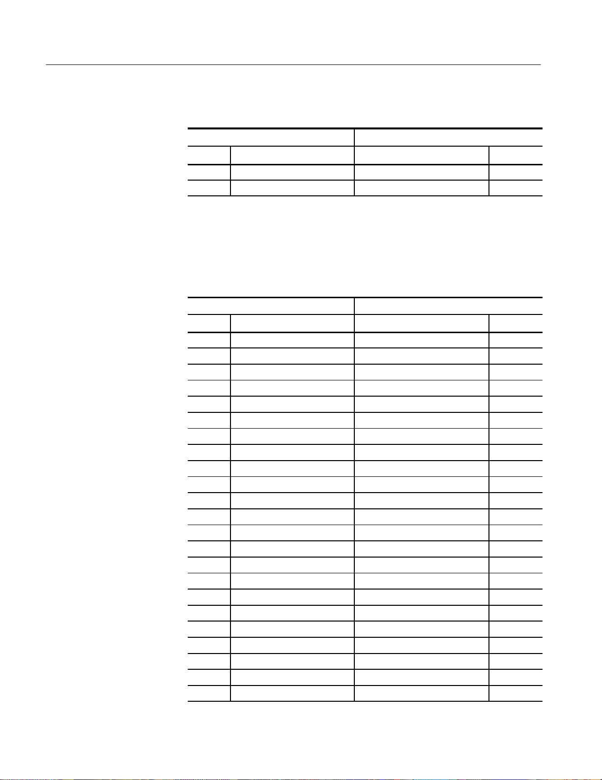
Table 2–1 shows the name, bit pattern, and meaning for the symbols in the
Control group symbol table. The Control group symbol table file name is
MBus-2_Ctrl.
2–2
LADM934 MBus Bus Support Instruction Manual
Online version
Page 25

T able 2–1: Control group symbol table definitions
Control group value
Symbol
CRI
WRDY~ MAD39
MERR~ MSI_L MAD39
101100101
WRDY~ MAD38
MSH_L MAD37
Operating Basics
Meaning
Coherent Read and Invalidate
CRI_O_DATA
CWI
CR_Sh_Data
CR_O_Data_LLM
CR_O_Data_FM
CI
RD
WR
IDLE
R&R
Valid_Data
Bus_Error
Timeout
Uncorrectable
101100101
101XX0100
101010011
101000011
101110011
101XX0010
101XX0001
101XX0000
111XXXXXX
110XXXXXX
101XXXXXX
011XXXXXX
010XXXXXX
001XXXXXX
Coherent Read and Invalidate
(of owned data)
Coherent Write and Invalidate
Coherent Read and Invalidate
(of Shared Data)
Coherent Read of Owned data
(long-latency memory)
Coherent Read of Owned data
(fast memory)
Coherent Invalidate
Any memory or I/O read
Any memory or I/O write
Idle Cycles
Relinquish and Retry
Valid Data Transfer
Bus Error
Timeout
Uncorrectable
Retry*
Undefine
* Symbols used only for triggering with the Internal or External clock mode; they do
not appear in the Disassembly or State displays.
Table 2–2 shows the name, bit pattern, and meaning for the symbols in the Size
group symbol table. The Size group symbol table file name is MBus-2_Size.
LADM934 MBus Bus Support Instruction Manual
Online version
000XXXXXX
XXXXXXXXX
Retry
Reserved for future use or undefined
2–3
Page 26

Operating Basics
T able 2–2: Size group symbol table definitions
Size group value
MAD39
Symbol
MAD37
MAD39
Meaning
Byte
Half-word
Word
Double-word
16-byte-Burst
32-byte-Burst
64-byte-Burst
128-byte-Burst
000
001
010
011
100
101
110
111
Byte access (8 bits)
Half word access (16 bits)
Word access (32 bits)
Double word access (64bits)
Burst 16 bytes
Burst 32 bytes
Burst 64 bytes
Burst 128 byte
Table 2–3 shows the name, bit pattern, and meaning for the symbols in the Irl_0
and Irl_1 group symbol table. The Irl_0 and Irl_1 group symbol table file name
is MBus-2_Intr.
T able 2–3: lrl_0 and lrl_1 group symbol table definition
Irl_0 and Irl_1 group value
IRL[3]
IRL[2]
Symbol
INT 15
IRL[1]
IRL[0]
1111
Meaning
Interrupt Request Level 15
2–4
INT 14
INT 13
INT 12
INT 11
INT 10
INT 9
INT 8
INT 7
INT 6
INT 5
INT 4
1110
1101
1100
1011
1010
1001
1000
0111
0110
0101
0100
Interrupt Request Level 14
Interrupt Request Level 13
Interrupt Request Level 12
Interrupt Request Level 11
Interrupt Request Level 10
Interrupt Request Level 9
Interrupt Request Level 8
Interrupt Request Level 7
Interrupt Request Level 6
Interrupt Request Level 5
Interrupt Request Level 4
LADM934 MBus Bus Support Instruction Manual
Online version
Page 27

T able 2–3: lrl_0 and lrl_1 group symbol table definition (Cont.)
Irl_0 and Irl_1 group value
IRL[3]
IRL[2]
Symbol Meaning
INT 3
IRL[1]
IRL[0]
0011
Interrupt Request Level 3
Operating Basics
INT 2
INT 1
–
0010
0001
0000
Interrupt Request Level 2
Interrupt Request Level 1
No Interrupt
Refer to Displaying Channel Groups Symbolically in this section for more
information on displaying symbolic values. Refer also to Searching Through
Disassembled Data in this section for information on how to use symbol table
values for 92C96 data searches.
Copying and Editing the Predefined Symbol Tables. You cannot directly edit any
symbol tables supplied by bus support. But you can make a copy of a predefined
symbol table and then edit the copy for your specific use.
To create a new symbol table, follow these steps:
1. Select the Symbol Editor menu from the Menu Selection overlay.
2. Press F2: FILE FUNCTIONS.
3. Select Open File in the Function field, and press Return.
4. Select New File in the Edit Status field, and press Return.
5. Enter a new symbol table file name in the New File Name field.
6. Select Pattern or Range in the Table Type field to match the symbol table
you are copying, and press Return.
7. Press F5: EXECUTE FUNCTION.
8. Select Merge Files in the Function field, and press Return.
9. Select the file to base your new symbol table on, such as the MBus-2_Ctrl
file.
10. Press F5: EXECUTE FUNCTION.
11. Press F8: EXIT & SAVE.
12. Edit the file as desired keeping the following in mind:
LADM934 MBus Bus Support Instruction Manual
Online version
2–5
Page 28

Operating Basics
H
If the new symbol has fewer don’t cares than an existing symbol, it must
be placed ahead of the existing symbol.
H
If the new symbol has more don’t cares than an existing symbol, it must
be placed after the existing symbol.
H
Do not duplicate symbol names.
Also refer to your system user manual for more information on editing the
symbol table.
13. Select the Channel menu from the Menu Selection overlay.
14. Change the file name of the symbol table for the Control group (or the
group’s symbol table you are replacing) to the one that you specified in
step 5.
Acquiring and Displaying Disassembled Data
Acquiring Data
This part of this section describes how to acquire data and view it disassembled
in the Disassembly menu of the DAS. These descriptions include:
H
Acquiring data
H
Viewing disassembled data in various formats
H
Functions of the Disassembly Format Definition overlay
H
Displaying groups symbolically
H
Searching through data
H
Printing data
H
Viewing the demonstration reference memory
Once you load the MBus-2 Support, choose a clocking mode, and specify the
trigger, you are ready to acquire and disassemble data.
On the DAS, press the F1: START acquisition key to begin the acquisition. You
can press the F1: STOP key at any time to stop acquisition.
If you have any problems acquiring data, refer to Appendix A: Error Messages
and Disassembly Problems.
2–6
LADM934 MBus Bus Support Instruction Manual
Online version
Page 29

Operating Basics
Viewing Disassembled
Data
Disassembled data is displayed in the Disassembly menu of the DAS in four
different formats: Hardware, Software, Control Flow, and Subroutine (State
display is also a selection you can choose, but you will not see disassembled
data.)
To select a format in the Disassembly menu of the DAS, follow these steps:
1. Press the Select Menu key and select the Disasm menu.
2. Press F5: DEFINE FORMAT.
3. Select the desired format in the Display Mode field.
4. Press F8: EXIT & SAVE.
You can select the display format and tailor it for your application using the
Disassembly Format Definition overlay. Figure 2–1 shows an example of MBus
data.
NOTE. Selections in the Disassembly Format Definition overlay must be set
correctly in order for your acquired data to be disassembled correctly. Refer to
Disassembly Format Definition Overlay later in this section.
Hardware Display Format. The Hardware display format shows the Hi,
P_Addr_L, Data_H, and Data_L channels for each sample of acquired data. In
Hardware data format, all bus cycles are shown in the order that they occurred.
Instruction Mnemonics are displayed on assumed instruction Fetch cycles and
cycle-type information is displayed for all other cycles. The disassembler cannot
detect flushes following a branch instruction. Non-instruction bus cycles are
displayed as either 32-bit or 64-bit wide data transfers.
The Hi group column in the Disassembly display shows the high-order 4 bits of
the address. If your MBus system is restricted to a 32-bit physical address, you
can make this group invisible in the Disassembly Format Definition overlay.
However, making this group invisible will not stop the disassembler from
displaying the appropriate value in the operand.
The P_Addr_L group column in the Disassembly display shows value for the
low-order 32 bits of the address at each sequence. The module latches the value
during the address part of the MAD bus as P_Addr_L, and, based on that value,
the disassembler synthesizes the addresses for the data cycles.
For block reads and writes, the calculated address follows the rules of Sub-block
Ordering. For each double-word cycles, the address calculated for the first line
will be modulo-8 and the address calculated for the second line will be modulo-8
plus 4.
LADM934 MBus Bus Support Instruction Manual
Online version
2–7
Page 30

Operating Basics
The Data_H and Data_L in the Disassembly shows value for the data part of the
MAD bus. Valid data bytes of the data will be shown during data transfers. All
invalid bytes will be dashed (– –) out.
Due to superscaler architecture, the SuperSPARC microprocessor reads two
instructions simultaneously. If the microprocessor cannot execute two instructions simultaneously, it reads the same instructions again. Since the bus does not
indicate which instruction was executed or not, instruction mnemonics are
displayed on all assumed instruction fetch cycles.
Table 2–4 shows cycle type labels and gives a definition of the cycle they
represent.
T able 2–4: Cycle type definitions
Cycle type Definition
( IDLE )
Idle cycles
( Relinquish & Retry )
( ERROR 1: Bus Error )
( ERROR 2: Bus Timeout )
( ERROR 3: Bus Uncorrectable )
( CRI )
( CRI Owned Data )
( CWI )
( CR Shared Data )
( CR Owned Data LLM )
( CR Owned Data FM )
(CI)
(RD)
(WR)
( Undefine )
Relinquish and retry
Bus error
Timeout
Uncorrectable
Coherent read and invalidate
Coherent read and invalidate of owned data
Coherent write and invalidate
Coherent read and invalidate of shared data
Coherent read of owned data (long-latency
memory)
Coherent read of owned data (fast memory)
Coherent invalidate
Any memory or I/O read
Any memory or I/O write
Undefined
Figure 2–1 shows an example of disassembled MBus data in the Hardware
display format.
2–8
LADM934 MBus Bus Support Instruction Manual
Online version
Page 31

Operating Basics
Sequence Hi P_Addr_L Data_H Data_L Mnemonic
------------------------------------------------------------------- 9 F F00109A0 01000000 10800010 NOP
F F00109A4 01000000 10800010 BA F:F00109E4
10 F F00109A8 01000000 A8102700 NOP
F F00109AC 01000000 A8102700 OR %g0, 0700, %l4
11 F F00109E0 EAA00080 27380004 STA %l5, [%g0 + %g0] 04
F F00109E4 EAA00080 27380004 SETHI 380004, %l3
12 F F00109E8 A614E008 EC84C5E0 OR %l3, 0008, %l3
F F00109EC A614E008 EC84C5E0 LDA [%l3 + %g0] 2F, %l6
13 F F00109F0 AC2DA00E EA800080 ANDN %l6, 000E, %l6
F F00109F4 AC2DA00E EA800080 LDA [%g0 + %g0] 04, %l5
14 F E0001008 00000003 -------- ( RD )
15 F F00109F8 A935601C 80A52000 SRL %l5, 001C, %l4
F F00109FC A935601C 80A52000 SUBcc %l4, 0000, %g0
16 F F00109F8 A935601C 80A52000 SRL %l5, 001C, %l4
F F00109FC A935601C 80A52000 SUBcc %l4, 0000, %g0
17 F F0010A00 22800005 A8102008 BE, a F:F0010A14
F F0010A04 22800005 A8102008 OR %g0, 0008, %l4
18 F F0010A08 A935600F 1080000A SRL %l5, 000F, %l4
F F0010A0C A935600F 1080000A BA F:F0010A34
19 F F0010A10 A80D200F 808D6800 AND %l4, 000F, %l4
F F0010A14 A80D200F 808D6800 ANDcc %l5, 0800, %g0
Figure 2–1: Disassembled data in the Hardware display format
Software display Format. The Software display format displays all assumed
instruction fetches. Labels that indicate the beginning of exception handler
routines are displayed. All other cycle types are suppressed. The disassembler
cannot detect flushes following branch instruction. The display is designed to
resemble assembly language listings.
Control Flow Display Format. The Control Flow display format shows instructions
that change the flow of control. Some instructions that do not actually change the
control flow are displayed, such as a conditional branch that is not taken.
Exception handler entry labels and the instruction at that location will be
displayed for control flow instructions. The label is always displayed regardless
of the type of instruction.
Subroutine Display Format. The Subroutine display format shows the first fetch of
subroutine calls and return instructions. Subroutine call are assumed to be branch
and jump instructions that perform a link. Because the disassembler cannot
detect when a flush occurs, conditional branches are always displayed.
LADM934 MBus Bus Support Instruction Manual
Online version
2–9
Page 32

Operating Basics
Disassembly Format
Definition Overlay
The Disassembly Format Definition overlay allows you to make optional display
selections for the Disassembly menu and tailor it for your applications.
You can use this overlay to do the following:
H
Choose the format (mode) in which the Disassembly menu displays
disassembled data
H
Set the interval in which the data cursor will scroll through disassembled
data
H
Display and define the format of the timestamp
H
Highlight various types of disassembled cycles
H
Choose to disassemble across gaps
H
Specify the starting address of the trap area
H
Specify the total number of traps
H
Specify the starting address of program code area
H
Specify the size of program code area
H
Change the position of any channel group in the display
H
Change the radix for any channel group
H
Choose which symbol tables are to be used when channel groups are
displayed symbolically
Press F5: DEFINE FORMAT from the Disassembly menu to see the overlay.
The following paragraphs describe the fields and selections available in the
Disassembly Format Definition overlay.
Display Mode. You can select Hardware, Software, Control Flow, or Subroutine
format.
Timestamp. You can display the timestamp as an Absolute, Relative, or Delta
value. You can also set the timestamp display to Off.
Timestamp values show the amount of time that has elapsed between data
samples. An Absolute timestamp shows the amount of time elapsed between
when the acquisition was started (after pressing F1: START) and each subsequent data sample. A Relative timestamp shows the amount of time elapsed
between successive samples. A Delta timestamp shows the amount of time
elapsed between the sample with the delta user mark and each previous or
subsequent data sample.
2–10
LADM934 MBus Bus Support Instruction Manual
Online version
Page 33

Operating Basics
Scroll By. You can scroll by Sequence, Instruction, Control Flow, or Subroutine.
Highlight. You can highlight Instructions, Control Flow, or Subroutines. With
highlighting on, only the selected type of samples are shown as white text with a
black background; all other samples are shown as gray text with a black
background. You can also set the highlighting to Off.
Highlight Gaps. You can choose to highlight or not to highlight gaps. Gaps are
caused by qualifying data storage in the Trigger menu and are indicated by a gray
background behind the address values.
Disasm Across Gaps. You can choose to continue or not to continue to disassemble data across gaps. Disassembling data across gaps causes the disassembler
to disassemble data as if no gap existed. Disassembled data will be invalid if the
last sample before the gap does not logically match the sample immediately
following the gap.
Trap Base Address. You must enter the base address for the trap area. The default
trap area base value is 0.
T otal Number of Traps. You must enter the total number of hardware and software
traps. The default number of traps is 100.
Program Area Begin [35-32]. Since the MBus does not indicate whether a read is
filling the instruction cache or the data cache, you must enter the upper four bits
of the beginning address and size of the program code area. The default value
is F.
The disassembler assumes that read cycles are instructions within the address
range specified in the Program Area Begin fields and the Program Area Size
field.
Program Area Begin [31-0]. Since the MBus does not indicate whether a read is
filling the instruction cache or the data cache, you must enter the lower 32 bits of
address and size of the program code area. The default value is F0000000.
Program Area Size. You can enter the size of the program code area. The default
value is 100000.
LADM934 MBus Bus Support Instruction Manual
Online version
2–11
Page 34

Operating Basics
Group Name. You can specify the name of the group that displays in the column
in which the cursor is positioned. When you move a group, the group is inserted
in the new column position and removed from its old position. Remaining
groups will move one column position to the left or right as appropriate.
Group Radix. You can select the radix in which each group displays. The radix
selections for most groups are Binary, Octal, Hexadecimal, Symbol, and Off.
The only selections for the Data group are Hexadecimal or Off. The only
selections for Mnemonics group are ASCII or Off. You should only select the
symbolic radix when a symbol table is available for that group. The timestamp
value always displays in decimal.
Symbol Table. You can specify a symbol table to use for each group where
symbolic is the selected radix.
F1: ESCAPE & CANCEL. Closes the overlay and discards any changes you
have made since entering it.
Displaying Channel
Groups Symbolically
F5: RESTORE FORMAT. Displays a list of saved disassembly formats for the
current module or cluster setup. Use the cursor keys to select the desired format
to restore, and press the Open/Close key.
F6: SAVE FORMAT. Saves the current selections for the Disassembly Format
Definition overlay in a file on disk. You can enter a file name up to ten characters
long.
F7: DELETE FORMAT. Displays a list of saved disassembly format files for
the current module or cluster setup. Use the cursor keys to select the desired
format to delete, and press the Open/Close key. You cannot delete the Default
format.
F8: EXIT & SAVE. Exits the overlay and executes or saves any changes made.
Any channel group can be displayed as symbolic values in the Disassembly
menu similar to the way the Control group can be displayed as symbolic values.
If you create a range symbol table for the Address group, the address will also
be displayed symbolically when it appears in the operand field of a mnemonic.
You can use the Symbol Editor menu to create symbol tables in which symbols
are assigned to various channel group values (ranges or patterns). You can then
change the radix of the channel group in the Disassembly menu using the
Disassembly Format Definition overlay, and select the symbol table you created
to use for display, triggering, or data search purposes.
2–12
LADM934 MBus Bus Support Instruction Manual
Online version
Page 35

Operating Basics
Searching Through
Disassembled Data
The MBus application does not have a Disassembly Search Definition overlay.
However, you can effectively search through disassembled data by following
these steps:
1. Press F2: SPLIT DISPLAY to use the split-screen display.
2. Press F5: SPLIT HORIZ to split the screen into two horizontal displays.
3. Press F2: LOCK CURSOR. A list of selections appears.
4. Select lock cursors at the same sequence, and press Return.
5. Press F8: EXIT & SAVE to display the menus in a split screen.
6. If the active window is the Disassembly menu, press F3: SWITCH
WINDOWS to make the State menu active. The cursor and Cursor field are
yellow in the active window.
7. Press F6: DEFINE SEARCH to use the search function of the State menu
to search for the desired sequence.
To search on Control group values, change the radix to binary and refer to
Table 2–1 in this section to find the binary equivalent values for the cycles you
want to locate. You can also use this method to search on binary equivalent
values for other channel groups with symbol tables.
Printing Disassembled
Data
Reference Memory
When searching for data in a clustered module setup in the State menu, the
searches are conducted only for the master module. You can, however, define
either module to be the master module. Refer to the description of the State
Search Definition overlay in your 92C96 Module User Manual for a description
of how to search through state data. Also refer to that manual for a description of
how to return to a full screen display.
To abort a search, press the Esc (escape) key.
To print disassembled data, use the Disassembly Print overlay. To access this
overlay, press the Print Screen key from the Disassembly menu. The Disassembly Print overlay is exactly the same as the State Print overlay. Refer to your
module user manual for a description of this overlay.
A demonstration reference memory file is provided so you can see an example of
how data from your system based on a SuperSPARC microprocessor using
MBus protocol looks when it is displayed. Viewing the reference memory is not
a requirement for preparing the 92C96 module for use. You can view the
reference memory file without connecting the DAS to your SUT.
LADM934 MBus Bus Support Instruction Manual
Online version
2–13
Page 36

Operating Basics
To view the MBus_Demo Refmem, follow these steps:
1. Press the Select Menu key and select the MBus_Demo file from the
2. Select the Disasm menu from the Display column and press Return.
You can change the display of disassembled data from the Disassembly Format
Definition overlay, which you can access through the Disassembly menu.
If there is not enough free space on the hard disk, you can delete the
MBus_Demo reference memory file. They are not necessary to the operation of
the application.
General Purpose Analysis
You may need to perform general purpose (timing) analysis on your MBus
system prior to, during, and after attempting to integrate your software with the
MBus system hardware. When performing hardware analysis, you will want to
use the data acquisition module to acquire data with a finer resolution. When
more data samples are taken in a given period of time, the resolution in the
Timing display increases, letting you see signal activity that would otherwise go
undetected.
Refmem column.
This part of this section provides information on the following:
H
Timing analysis
H
State analysis
H
Displaying data
H
Supplied Timing Format Definition file
Keep in mind when you view state data in the State menu (92C96) that it uses
the default channel grouping setup with all groups visible and that disassembly
does not occur. All channel groups will display in the default order and and will
look different than disassembled data.
Refer to the channel assignment tables in the Specifications section to see which
channels are not required for disassembly. You can disconnect these channels to
make other MBus system connections.
2–14
LADM934 MBus Bus Support Instruction Manual
Online version
Page 37

Operating Basics
Clocking
To change the data sampling rate, use the 92C96 Clock menu.
When using the 92C96 Module for timing analysis, you will want to use the
Internal or External clocking modes. The Internal clock selection can sample
data up to 100 MHz, which has a 10 ns resolution between samples. The
External clock selection samples data on every active clock edge on the 92C96
clock inputs up to 100 MHz.
The default clocking mode is Custom when MBus-2 Support is selected in the
Configuration menu; you will need to change it to either Internal or External.
Your module user manual contains an in-depth description of Internal and
External clocking.
Custom Clocking. Custom clocking only stores one data sample for each bus
transaction, which can take one or more clock cycles. Custom clocking also time
aligns certain signals that otherwise would be skewed relative to the current bus
transaction. This clocking selection is generally unproductive for timing
analysis. Refer to the Specifications section for a more in depth description of
how Custom clocking is used with the probe adapter to acquire data.
Internal Clocking. Because the Data_H and Data_L groups are demultiplexed
from the MAD bus by Custom Clocking, in Internal Clocking, this data cannot
be acquired and displayed. You should use MBus_Tmg_96 Module Setup for
timing analysis. Information on how to restore this setup is under Loading the
Application in the Getting Started section.
When you select Internal as the clocking mode, the 92C96 Module stores one
data sample as often as every 10 ns (100 MHz). This clocking selection is
commonly referred to as asynchronous.
Two typical uses of Internal clocking might be to verify that all the MBus signals
are transitioning as expected or to measure timing relationship between signal
transitions.
It is possible to acquire asynchronous data at rates of 200 MHz and 400 MHz.
The faster the 92C96 Module acquires data, the fewer channels it can acquire
data on. A single 92C96 Module can acquire data on 24 channels at 400 MHz or
2.5 ns resolution. Refer to your 92C96 Module User Manual for information on
sampling data at speeds faster than 100 MHz.
External Clocking. Because the Data_H and Data_L groups are demultiplexed
from the MAD bus by Custom Clocking, in External Clocking, this data cannot
be acquired and displayed. You should use MBus_Tmg_96 Module Setup for
timing analysis. Information on how to restore this setup is under Loading the
Application in the Getting Started section.
LADM934 MBus Bus Support Instruction Manual
Online version
2–15
Page 38

Operating Basics
When you select External as the clocking mode, the 92C96 Module acquires and
stores data based on the clock channel up to 100 MHz. This clocking selection
is commonly referred to as synchronous.
Searching Through State
and Timing Data
Printing State and Timing
Data
Timing Display
To search through 92C96 data, you can use either the Timing Search Definition
overlay or the State Search Definition overlay. You can use these overlays and
search through data as described in your 92C96 Module User Manual.
Before performing a search in the Timing menu, be sure to check the State
Format Definition overlay and make sure the channels on which you want to
conduct the search will be displayed (radix is not Off). Channels in the TIming
menu cannot be searched on unless they can also be displayed in the State menu.
To print 92C96 state data, you can use the State Table Print overlay. To access
this overlay, press the Shift and Print keys at the same time from the State menu.
To print timing data, you can use the Timing Print overlay. To access this
overlay, press the Shift and Print keys at the same time from the Timing menu.
For detailed information on the State Table Print overlay or the Timing Print
overlay, refer to your 92C96 Module User Manual.
General purpose analysis requires that you view data in either the State or
Timing display menus (or both). In the Timing display, every channel is shown
as a waveform, and groups of channels (such as the P_Addr_L group) are shown
as bus forms.
2–16
Two predefined Timing Format Definition overlay files, part of the MBus
support product, are available for you to use when viewing data in the Timing
display. The MBus-2_96 and MBus_Tmg_96 files are installed on the DAS
when you install the application.
The MBus-2_96 Timing Format Definition file places the Hi, P_Addr_L,
Data_H, and Data_L groups first and displays them as bus forms containing bus
values instead of as individual timing waveforms. These groups are followed by
other important control signals.
The MBus_Tmg_96 Timing Format Definition file places the MAD_H and
MAD_L groups first and displays them as bus forms containing bus values
instead of as individual timing waveforms. These groups are followed by other
important control signals.
To select a supplied Timing Format Definition file, follow these steps:
1. Press the Select Menu key, select the Timing menu and press F5: DEFINE
FORMAT.
2. Press F5: RESTORE FORMAT.
LADM934 MBus Bus Support Instruction Manual
Online version
Page 39

Operating Basics
3. Select MBus_96 if you are using the MBus-2 Support setup, or select
MBus_Tmg_96 if you are using the MBus_Tmg_96 Module setup and press
the Return key.
4. Press F8: EXIT & SAVE to return to the Timing menu.
Refer to the channel assignment tables in the Specifications section for the lists
of individual channels and their MBus signal names.
State Display
In the State menu, all channel group values are shown based on the selected
radix in the Channel menu or the State Format Definition overlay. Disassembly
does not occur.
If you want to display other channel groups (such as Misc), access the State
Format Definition overlay and change the radix for the group from Off to Hex,
Bin, or Oct. This overlay also allows you to add the Timestamp group (and
change the radix) to the data display.
LADM934 MBus Bus Support Instruction Manual
Online version
2–17
Page 40

Specifications
This section contains the following information:
H
H
H
H
Probe Adapter Description
The probe adapter is a nonintrusive piece of hardware that allows the 92C96 to
acquire data from an MBus in its own operating environment with little affect, if
any, on that system. Refer to the DAS overview figure in the Getting Started
section while reading the next paragraph.
The probe adapter consists of a circuit board and a socket for the MBus. The
probe adapter connects to the bus in the SUT (system under test). Signals from
the MBus system flow from the probe adapter to the probes (podlet groups). The
signals flow through the probe signal leads to either the 92C96 Acquisition
Module.
Brief description of the probe adapter
Channel assignment tables
Description of how the 92C96 Module acquires MBus signals
List of accessible MBus signals and extra 92C96 channels
All circuitry on the probe adapter is powered from the SUT.
The probe adapter accommodates the MBus signals in a 100-pin connector.
There is one jumper, J150, used to set the MCLK signal source on the probe
adapter for proper clocking. The jumper position must match the MCLK signal
used in the SUT: MCLK1, MCLK1, MCLK2, or MCLK3. A description of
configuring the probe adapter is located in the Operating Basics section.
Figure 3–1 shows the dimensions of the probe adapter.
LADM934 MBus Bus Support Instruction Manual
Online version
3–1
Page 41

Specifications
84 mm
(3.30 in)
146 mm
(5.75 in)
Channel Assignments
43 mm
(1.70 in)
17 mm
(6.50 in)
Figure 3–1: Minimum clearance of the probe adapter
Channel assignments shown in Table 3–1 through Table 3–20 use the following
conventions:
H
All signals are required for disassembly (MBus-2 Support with Custom
clocking) or general purpose analysis (MBus_Tmg_96 Module Setup with
External or Internal clocking) unless indicated otherwise
H
Channels are shown starting with the most significant bit (MSB) descending
to the least significant bit (LSB)
3–2
H
A tilde sign (~) following a signal name indicates an active low signal
H
An equals sign (=) following a signal name indicates that the signal is double
probed
LADM934 MBus Bus Support Instruction Manual
Online version
Page 42

Specifications
H
The module in the higher-numbered slot is referred to as the HI module; the
module in the lower-numbered slot is referred to as the LO module
MBus-2 Support Setup
Tables 3–1 through 3–12 show the channel assignments for the MBus-2 Support
setup used to disassemble data with Custom clocking.
Table 3–1 shows the 92C96 section and channel assignments for the V_Addr
group, and the MBus signal and pin number to which each channel connects.
The default display radix is OFF.
T able 3–1: MBus-2: V_Addr group channel assignments
Acq. module bit order and channel MBus
Bit no. 92C96 Signal name Pin no.
7 HI_A2:5 MAD53 80
6 HI_A2:4 MAD52 79
5 HI_A2:3 MAD51 78
4 HI_A2:2 MAD50 77
3 HI_A2:1 MAD49 76
2 HI_A2:0 MAD48 75
1 LO_A3:7 MAD47 74
0 LO_A3:6 MAD46 73
Table 3–2 shows the 92C96 section and channel assignments for the Hi group,
and the MBus signal and pin number to which each channel connects. The
default display radix is Hex.
T able 3–2: MBus-2: Hi group channel assignments
Acq. module bit order and channel MBus
Bit no. 92C96 Signal name Pin no.
3 LO_A2:3 MAD35 62
2 LO_A2:2 MAD34 61
1 LO_A2:1 MAD33 60
0 LO_A2:0 MAD32 59
Table 3–3 shows the 92C96 section and channel assignments for the P_Addr_L
group, and the MBus signal and pin number to which each channel connects.
The default display radix is Hex.
LADM934 MBus Bus Support Instruction Manual
Online version
3–3
Page 43

Specifications
T able 3–3: MBus-2: P_Addr_L group channel assignments
Acq. module bit order and channel MBus
Bit no. 92C96 Signal name Pin no.
31 HI_A1:7 MAD31 42
30 HI_A1:6 MAD30 41
29 HI_A1:5 MAD29 40
28 HI_A1:4 MAD28 39
27 HI_A1:3 MAD27 38
26 HI_A1:2 MAD26 37
25 HI_A1:1 MAD25 36
24 HI_A1:0 MAD24 35
23 HI_A0:7 MAD23 34
22 HI_A0:6 MAD22 33
21 HI_A0:5 MAD21 32
20 HI_A0:4 MAD20 31
19 HI_A0:3 MAD19 30
18 HI_A0:2 MAD18 29
17 HI_A0:1 MAD17 28
16 HI_A0:0 MAD16 27
15 LO_A1:7 MAD15 26
14 LO_A1:6 MAD14 25
13 LO_A1:5 MAD13 24
12 LO_A1:4 MAD12 23
11 LO_A1:3 MAD11 22
10 LO_A1:2 MAD10 21
9 LO_A1:1 MAD9 20
8 LO_A1:0 MAD8 19
7 LO_A0:7 MAD7 18
6 LO_A0:6 MAD6 17
5 LO_A0:5 MAD5 16
4 LO_A0:4 MAD4 15
3 LO_A0:3 MAD3 14
2 LO_A0:2 MAD2 13
1 LO_A0:1 MAD1 12
0 LO_A0:0 MAD0 11
3–4
LADM934 MBus Bus Support Instruction Manual
Online version
Page 44

Specifications
Table 3–4 shows the 92C96 section and channel assignments for the Data_H
group, and the MBus signal and pin number to which each channel connects.
The default display radix is HEX.
T able 3–4: MBus-2: Data_H group channel assignments
Acq. module bit order and channel MBus
Bit no. 92C96 Signal name Pin no.
31 HI_A3:7 MAD63 90
30 HI_A3:6 MAD62 89
29 HI_A3:5 MAD61 88
28 HI_A3:4 MAD60 87
27 HI_A3:3 MAD59 86
26 HI_A3:2 MAD58 85
25 HI_A3:1 MAD57 84
24 HI_A3:0 MAD56 83
23 HI_A2:7 MAD55 82
22 HI_D2:6 MAD54 81
21 HI_D2:5 MAD53 80
20 HI_D2:4 MAD52 79
19 HI_D2:3 MAD51 78
18 HI_D2:2 MAD50 77
17 HI_D2:1 MAD49 76
16 HI_D2:0 MAD48 75
15 LO_D3:7 MAD47 74
14 LO_D3:6 MAD46 73
13 LO_D3:5 MAD45 72
12 LO_D3:4 MAD44 71
11 LO_D3:3 MAD43 70
10 LO_D3:2 MAD42 69
9 LO_D3:1 MAD41 68
8 LO_D3:0 MAD40 67
7 LO_D2:7 MAD39 66
6 LO_D2:6 MAD38 65
5 LO_D2:5 MAD37 64
4 LO_D2:4 MAD36 63
3 LO_D2:3 MAD35 62
2 LO_D2:2 MAD34 61
LADM934 MBus Bus Support Instruction Manual
Online version
3–5
Page 45
Specifications
T able 3–4: MBus-2: Data_H group channel assignments (Cont.)
Acq. module bit order and channel MBus
Bit no. Pin no.Signal name92C96
1 LO_D2:1 MAD33 60
0 LO_D2:0 MAD32 59
Table 3–5 shows the 92C96 section and channel assignments for the Data_L
group, and the MBus signal and pin number to which each channel connects.
The default display radix is HEX.
T able 3–5: MBus-2: Data_L group channel assignments
Acq. module bit order and channel MBus
Bit no. 92C96 Signal name Pin no.
31 HI_D1:7 MAD31 42
30 HI_D1:6 MAD30 41
29 HI_D1:5 MAD29 40
28 HI_D1:4 MAD28 39
27 HI_D1:3 MAD27 38
26 HI_D1:2 MAD26 37
25 HI_D1:1 MAD25 36
24 HI_D1:0 MAD24 35
23 HI_D0:7 MAD23 34
22 HI_D0:6 MAD22 33
21 HI_D0:5 MAD21 32
20 HI_D0:4 MAD20 31
19 HI_D0:3 MAD19 30
18 HI_D0:2 MAD18 29
17 HI_D0:1 MAD17 28
16 HI_D0:0 MAD16 27
15 LO_D1:7 MAD15 26
14 LO_D1:6 MAD14 25
13 LO_D1:5 MAD13 24
12 LO_D1:4 MAD12 23
11 LO_D1:3 MAD11 22
10 LO_D1:2 MAD10 21
9 LO_D1:1 MAD9 20
3–6
LADM934 MBus Bus Support Instruction Manual
Online version
Page 46

Specifications
T able 3–5: MBus-2: Data_L group channel assignments (Cont.)
Acq. module bit order and channel MBus
Bit no. Pin no.Signal name92C96
8 LO_D1:0 MAD8 19
7 LO_D0:7 MAD7 18
6 LO_D0:6 MAD6 17
5 LO_D0:5 MAD5 16
4 LO_D0:4 MAD4 15
3 LO_D0:3 MAD3 14
2 LO_D0:2 MAD2 13
1 LO_D0:1 MAD1 12
0 LO_D0:0 MAD0 11
Table 3–6 shows the 92C96 section and channel assignments for the Control
group, and the MBus signal and pin number to which each channel connects.
The default display radix is SYM for MBus Support.
T able 3–6: MBus-2: Control group channel assignments
Acq. module bit order and channel MBus
Bit no. 92C96 Signal name Pin no.
8 HI_ & LO_C2:2 MERR~ 52
7 HI_ & LO_C2:3 MRDY~ 50
6 LO_C2:7 MRTY~ 48
5
4
3
2
1
0
LO_C2:5
LO_C2:4
LO_A2:7
LO_A2:6
LO_A2:5
LO_A2:4
MSH_L none
MIH_L none
MAD39 66
MAD38 65
MAD37 64
MAD36 63
Table 3–7 shows the 92C96 section and channel assignments for the Size group,
and the MBus signal and pin number to which each channel connects. The
default display radix is SYM for MBus Support.
LADM934 MBus Bus Support Instruction Manual
Online version
3–7
Page 47

Specifications
T able 3–7: MBus-2: Size group channel assignments
Acq. module bit order and channel MBus
Bit no. 92C96 Signal name Pin no.
2 LO_A3:2 MAD42 69
1 LO_A3:1 MAD41 68
0 LO_A3:0 MAD40 57
Table 3–8 shows the 92C96 section and channel assignments for the Irl_0 group,
and the MBus signal and pin number to which each channel connects. The
default display radix is SYM for MBus Support.
T able 3–8: MBus-2: lrl_0 group channel assignments
Acq. module bit order and channel MBus
Bit no. 92C96 Signal name Pin no.
3 LO_C0:3 IRL03*
2 LO_C0:2 IRL02*
1 LO_C0:1 IRL01*
0 LO_C0:0 IRL00*
* Signals not required for disassembly.
[
Signal is not available on the standard MBus connector; these are dedicated signals.
[
[
[
[
8
9
6
7
3–8
Table 3–9 shows the 92C96 section and channel assignments for the Irl_1 group,
and the MBus signal and pin number to which each channel connects. The
default display radix is SYM for MBus Support.
T able 3–9: MBus-2: lrl_1 group channel assignments
Acq. module bit order and channel MBus
Bit no. 92C96 Signal name Pin no.
3 LO_C3:1 IRL13*
2 LO_C3:0 IRL12*
1 LO_C1:1 IRL1 1*
0 LO_C1:0 IRL10*
[
[
[
[
95
94
93
92
* Signals not required for disassembly.
[
Signal is not available on the standard MBus connector; these are dedicated signals.
LADM934 MBus Bus Support Instruction Manual
Online version
Page 48

Specifications
Table 3–10 shows the 92C96 section and channel assignments for the JTAG
group, and the MBus signal and pin number to which each channel connects.
The default display radix is OFF.
T able 3–10: MBus-2: JTAG group channel assignments
Acq. module bit order and channel MBus
Bit no. 92C96 Signal name Pin no.
4 LO_C2:6 SCANCLK* 5
3 HI_C2:7 SCANTMS2* 4
2 HI_C2:6 SCANTMS1* 2
1 HI_C2:5 SCAND1*
0 HI_C2:4 SCAND0*
* Signals not required for disassembly.
[
Signal is not available on the standard MBus connector; these are dedicated signals.
[
[
1
3
Table 3–11 shows the 92C96 section and channel assignments for the Misc
group, and the MBus signal and pin number to which each channel connects.
The default display radix is OFF.
T able 3–11: MBus-2: Misc group channel assignments
Acq. module bit order and channel MBus
Bit no. 92C96 Signal name Pin no.
17
16
15
14
13
12
11
10
9
8
7
6
5
4
LO_C1:6
LO_C0:7
LO_C1:7
HI_ & LO_C2:1
HI_ & LO_C2:0
LO_C3:7
LO_C3:3
LO_C3:2
LO_C3:6
LO_C3:5
LO_C3:4
LO_C0:6
LO_C0:5
LO_C0:4
MBR1~*
MBR0~*
MBG0~*
MAS~ 54
MBB~ 56
MBG1~*
AEER~* 96
RSTIN~*
ID3*
ID2*
ID1*
MSH~* 44
MIH~* 46
INTOUT~* 10
[
[
[
[
[
[
[
[
55
43
45
57
97
100
99
98
LADM934 MBus Bus Support Instruction Manual
Online version
3–9
Page 49

Specifications
T able 3–11: MBus-2: Misc group channel assignments (Cont.)
Acq. module bit order and channel MBus
Bit no. Pin no.Signal name92C96
3
2
1
0
* Signals not required for disassembly.
[
LO_C1:5
LO_C1:4
LO_C1:3
LO_C1:2
Signal is not available on the standard MBus connector; these are dedicated signals.
MCLK3* 53
MCLK2* 51
MCLK1* 49
MCLK0* 47
Table 3–12 shows the 92C96 section and channel assignments for the clock
channels (not part of any group), and the MBus signal and pin number to which
each channel connects. These channels are used only to clock in data; they are
not acquired or displayed.
T able 3–12: MBus-2: Clock channel assignments
MBus
Acq. module and channel Signal name Pin no.
HI_ & LO_Clk:3 MBG1~= 57
HI_ & LO_Clk:2 MRTY~= 48
HI_ & LO_Clk:1 MBG0~= 45
HI_ & LO_Clk:0 MCLK none
MBus_Tmg_96 Module
3–10
Setup
Tables 3–13 through 3–20 show the channel assignments for the MBus_Tmg_96
Module setup used for general purpose analysis with External or Internal
clocking.
Table 3–13 shows the 92C96 section and channel assignments for the MAD_H
group, and the MBus signal and pin number to which each channel connects.
The default display radix is Hex.
LADM934 MBus Bus Support Instruction Manual
Online version
Page 50

Specifications
T able 3–13: MBus_Tmg_96: MAD_H group channel assignments
Acq. module bit order and channel MBus
Bit no. 92C96 Signal name Pin no.
31
30
29
28
27
26
25
24
23
22
21
20
19
18
17
16
15
14
13
12
11
10
9
8
7
6
5
4
3
2
1
0
HI_A3:7 MAD63
HI_A3:6
HI_A3:5
HI_A3:4
HI_A3:3
HI_A3:2
HI_A3:1
HI_A3:0
HI_A2:7
HI_A2:6
HI_A2:5
HI_A2:4
HI_A2:3
HI_A2:2
HI_A2:1
HI_A2:0
LO_A3:7
LO_A3:6
LO_A3:5
LO_A3:4
LO_A3:3
LO_A3:2
LO_A3:1
LO_A3:0
LO_A2:7
LO_A2:6
LO_A2:5
LO_A2:4
LO_A2:3
LO_A2:2
LO_A2:1
LO_A2:0
MAD61 89
MAD60 88
MAD59 87
MAD58 86
MAD57 85
MAD58 84
MAD56 83
MAD55 82
MAD54 81
MAD53 80
MAD52 79
MAD51 78
MAD50 77
MAD49 76
MAD48 75
MAD47 74
MAD46 73
MAD45 72
MAD44 71
MAD43 70
MAD42 69
MAD41 68
MAD40 67
MAD39 66
MAD38 65
MAD37 64
MAD36 63
MAD35 62
MAD34 61
MAD33 60
MAD32 59
90
LADM934 MBus Bus Support Instruction Manual
Online version
3–11
Page 51

Specifications
Table 3–14 shows the 92C96 section and channel assignments for the MAD_L
group, and the MBus signal and pin number to which each channel connects.
The default display radix is HEX.
T able 3–14: MBus_Tmg_96: MAD_L group channel assignments
Acq. module bit order and channel MBus
Bit no. 92C96 Signal name Pin no.
31
30
29
28
27
26
25
24
23
22
21
20
19
18
17
16
15
14
13
12
11
10
9
8
7
6
5
4
HI_A1:7 MAD31
HI_A1:6
HI_A1:5
HI_A1:4
HI_A1:3
HI_A1:2
HI_A1:1
HI_A1:0
HI_A0:7
HI_A0:6
HI_A0:5
HI_A0:4
HI_A0:3
HI_A0:2
HI_A0:1
HI_A0:0
LO_A1:7
LO_A1:6
LO_A1:5
LO_A1:4
LO_A1:3
LO_A1:2
LO_A1:1
LO_A1:0
LO_A0:7
LO_A0:6
LO_A0:5
LO_A0:4
MAD30 41
MAD29 40
MAD28 39
MAD27 38
MAD26 37
MAD25 36
MAD24 35
MAD23 34
MAD22 33
MAD21 32
MAD20 31
MAD19 30
MAD18 29
MAD17 28
MAD16 27
MAD15 26
MAD14 25
MAD13 24
MAD12 23
MAD1 1 22
MAD10 21
MAD9 20
MAD8 19
MAD7 18
MAD6 17
MAD5 16
MAD4 15
42
3–12
LADM934 MBus Bus Support Instruction Manual
Online version
Page 52

Specifications
T able 3–14: MBus_Tmg_96: MAD_L group channel assignments (Cont.)
Acq. module bit order and channel MBus
Bit no. Pin no.Signal name92C96
3
2
1
0
LO_A0:3
LO_A0:2
LO_A0:1
LO_A0:0
MAD3 14
MAD2 13
MAD1 12
MAD0 11
Table 3–15 shows the 92C96 section and channel assignments for the Control
group, and the MBus signal and pin number to which each channel connects.
The default display radix is BIN for MBus Support.
T able 3–15: MBus_Tmg_96: Control group channel assignments
Acq. module bit order and channel MBus
Bit no. 92C96 Signal name Pin no.
4
3
2
1
0
LO_C2:2
LO_C2:3
LO_C2:7
LO_C2:5
LO_C2:4
MERR~ 52
MRDY~ 50
MRTY~ 48
MSH_L none
MIH_L none
Table 3–16 shows the 92C96 section and channel assignments for the Intr_0
group, and the MBus signal and pin number to which each channel connects.
The default display radix is SYM for MBus Support.
T able 3–16: MBus_Tmg_96: lntr_0 group channel assignments
Acq. module bit order and channel MBus
Bit no. 92C96 Signal name Pin no.
3 LO_C0:3 IRL03* 8
2 LO_C0:2 IRL02* 9
1 LO_C0:1 IRL01* 6
0 LO_C0:0 IRL00* 7
* Signal is not available on the standard MBus connector; these are dedicated signals.
LADM934 MBus Bus Support Instruction Manual
Online version
3–13
Page 53

Specifications
Table 3–17 shows the 92C96 section and channel assignments for the Intr_1
group, and the MBus signal and pin number to which each channel connects.
The default display radix is SYM for MBus Support.
T able 3–17: MBus_Tmg_96: lntr_1 group channel assignments
Acq. module bit order and channel MBus
Bit no. 92C96 Signal name Pin no.
3 LO_C3:1 IRL13* 95
2 LO_C3:0 IRL12* 94
1 LO_C1:1 IRL1 1* 93
0 LO_C1:0 IRL10* 92
* Signal is not available on the standard MBus connector; these are dedicated signals.
Table 3–18 shows the 92C96 section and channel assignments for the JTAG
group, and the MBus signal and pin number to which each channel connects.
The default display radix is OFF.
T able 3–18: MBus_Tmg_96: JTAG group channel assignments
Acq. module bit order and channel MBus
Bit no. 92C96 Signal name Pin no.
4 LO_C2:6 SCANCLK 5
3 HI_C2:7 SCANTMS2 4
2 HI_C2:6 SCANTMS1 2
1 HI_C2:5 SCAND1* 1
0 HI_C2:4 SCAND0* 3
* Signal is not available on the standard MBus connector; these are dedicated signals.
Table 3–19 shows the 92C96 section and channel assignments for the MISC
group, and the MBus signal and pin number to which each channel connects.
The default display radix is OFF.
T able 3–19: MBus_Tmg_96: MISC group channel assignments
Acq. module bit order and channel MBus
Bit no. 92C96 Signal name Pin no.
17
16
15
LO_C1:6
LO_C0:7
LO_C1:7
MBR1~* 55
MBR0~* 43
MBG0~* 45
3–14
LADM934 MBus Bus Support Instruction Manual
Online version
Page 54

T able 3–19: MBus_Tmg_96: MISC group channel assignments (Cont.)
Acq. module bit order and channel MBus
Bit no. Pin no.Signal name92C96
Specifications
14
13
12
11
10
9
8
7
6
5
4
3
2
1
0
* Signal is not available on the standard MBus connector; these are dedicated signals.
LO_C2:1
LO_C2:0
LO_C3:7
LO_C3:3
LO_C3:2
LO_C3:6
LO_C3:5
LO_C3:4
LO_C0:6
LO_C0:5
LO_C0:4
LO_C1:5
LO_C1:4
LO_C1:3
LO_C1:2
MAS~ 54
MBB~ 56
MBG1~* 57
AEER~ 96
RSTIN~* 97
ID3* 100
ID2* 99
ID1* 98
MSH~ 44
MIH~ 46
INTOUT~ 10
MCLK3 53
MCLK2 51
MCLK1 49
MCLK0 47
Table 3–20 shows the 92C96 section and channel assignments for the clock
channels (not part of any group), and the MBus signal and pin number to which
each channel connects. These channels are used only to clock in data; they are
not acquired or displayed.
T able 3–20: MBus_Tmg_96: Clock channel assignments
Acq. module and channel Signal name Pin no.
HI_ & LO_Clk:3 MBG1~= 57
HI_ & LO_Clk:2 MRTY~= 48
HI_ & LO_Clk:1 MBG0~= 45
HI_ & LO_Clk:0 MCLK none
LADM934 MBus Bus Support Instruction Manual
Online version
MBus
3–15
Page 55

Specifications
How Data is Acquired
This part explains how the acquisition module acquires MBus signals using the
MBus probe adapter and application It also provides additional information on
MBus signals accessible on or not accessible on the probe adapter, and on extra
92C96 channels available for you to use for additional connections.
A special clocking program is loaded to the acquisition module every time the
MBus-2 Support is selected in the Configuration menu. The module logs in
signals from multiple groups of channels at different times when they are valid
on the MBus bus. The module then sends all the logged in signals to the trigger
machine and to the acquisition memory of the module for storage.
In Custom clocking, the module’s clocking state machine (CSM) generates one
master sample for each MBus bus cycle, no matter how many clock cycles are
contained in that cycle
.
Figure 3–2 shows the sample points and the master sample.
MCLK
MAS
MRDY
MAD(63:0)
VA19-VA12
PA35-PA0
Type3-Type0
Size2-Size0
MAH
MIH
* The Data_H, Data_L, IRL03-IRL00, IRL13-IRL10, ID3-ID1 and JTAG groups are logged.
Master
sample
point*
Master
sample
point*
Master
sample
point*
Master
sample
point*
Figure 3–2: MBus bus timing
MAS~ is active (low) whenever the Address, Size, and Type signals are present
on the MAD bus. These signals are latched internally until the next assertion of
the MAS~ signal. Data with this information is sampled by MCLK whenever the
MRDY~ signal is active (low). The probe adapter contains circuitry that latches
the MSH and MIH signals. The latched signal names are MSH_L and MIH_L.
3–16
LADM934 MBus Bus Support Instruction Manual
Online version
Page 56

Alternate Connections
Specifications
You can connect to MBus signals that are not required for disassembly so you
can do more advanced timing analysis. These signals might or might not be
accessible on the probe adapter board. The following paragraphs list signals
channels that are or are not accessible on the probe adapter board, and extra
92C96 channels.
For a list of signals required or not required for disassembly, refer to the channel
group assignment tables earlier in this section.
Signals Not On the Probe
Adapter
All MBus signals are accessible on the probe adapter. However, the probe
adapter only monitors common bus signals.
Dedicated signals in a standard MBus system are as follows:
H
Interrupt signals: IRL03-IRL00, IRL13-IRL10
H
Bus Arbitration Signals: MBR1, MBR0, MBG1, MBG0
H
Module ID signals: ID3-ID1
H
SCAND1, SCAND0, RSTIN
There are two ways to access dedicated MBus signals. One way is to jumper the
signals from the Target MPU to the probe adapter on the back of the board to
which the probe adapter connects. Figure 3–3 shows an example of how to
jumper connections for dedicated MBus signals.
7 6 9 8 92 94 9593
MBus Slot #2
(Probe adapter)
Connect these signals.
MBus Slot #1
(Target MPU)
View is from the backside of the board
to which the probe adapter connects
Figure 3–3: An example of jumper connections for dedicated MBus signals
The channel assignment tables in this section show the pin numbers for the
MBus connector. Since the MBus multiplexes Address and Data signals, pin
numbers for those signals are listed in two channel assignment tables.
LADM934 MBus Bus Support Instruction Manual
Online version
IPL1IPL0
3–17
Page 57

Specifications
Another way to access dedicated MBus signals is to use extra 92C96 channels to
connect directly to the signals in your SUT.
Extra Channels
Table 3–21 lists extra 92C96 channels that are left after you have connected all
the channels used by the application. You can use these extra channels to make
alternate connections to your SUT, such as to dedicated MBus signals. You can
also disconnect channels not required for disassembly to make alternate
connections. The channel assignment tables in this section indicate channels not
required for disassembly.
T able 3–21: Extra 92C96 groups and channels
92C96 group Channels 92C96 group Channels
HI_C3 7-0 LO_C3 7-0
HI_C2 7-4 LO_C2 6
HI_C1 7-0 LO_C1 7-0
HI_C0 7-0 LO_C0 7-0
3–18
LADM934 MBus Bus Support Instruction Manual
Online version
Page 58

WARNING
The following servicing instructions are for use only by qualified personnel. To
avoid injury, do not perform any servicing other than that stated in the operating
instructions unless you are qualified to do so. Refer to all Safety Summaries before
performing any service.
Page 59

Maintenance
Care and Maintenance
This section contains information on care and maintenance.
The probe adapter does not require scheduled or periodic maintenance. To
maintain good electrical contact, keep the probe adapter free of dirt, dust, and
contaminants. Also, ensure that any electrically conductive contaminants are
removed.
Dirt and dust can usually be removed with a soft brush. For more extensive
cleaning, use only a damp cloth. Abrasive cleaners and organic solvents should
never be used.
CAUTION. CAUTION. The semiconductor devices contained on the probe
adapter are susceptible to static–discharge damage. To prevent damage, service
the probe adapter only in a static–free environment.
If the probe adapter is connected to your system, grasp the ground lug on the
back of the DAS mainframe to discharge your stored static electricity. If the
probe adapter is not connected, touch any of the ground pins (row of square pins
closest to the edge of the probe adapter circuit board labeled GND) to discharge
stored static electricity from the probe adapter.
Always wear a grounding wrist strap, or similar device, while servicing the
instrument.
Exercise care when soldering on a multilayer circuit board. Excessive heat can
damage the throughhole plating or lift a run or pad and damage the board beyond
repair. Do not apply heat for longer than three seconds. Do not apply heat
consecutively to adjacent leads. Allow a moment for the board to cool between
each operation.
If you must replace an electrical component on a circuit board, exercise extreme
caution while unsoldering or soldering the new component. Use a penciltype
soldering iron of less than 18 watts and an approved unsoldering tool. Ensure
that the replacement is an equivalent part.
Removing And Replacing Signal Leads
Refer to your 92C96 module user manual for information on how to replace
signal leads.
LADM934 MBus Bus Support Instruction Manual
Online version
4–1
Page 60

Replaceable Parts
This section contains a list of the replaceable modules unique to the LADM934
Mbus support product. Use this list to identify and order replacement parts.
The basic operations user manual contains a list of common replaceable parts.
Parts Ordering Information
Replacement parts are available through your local Tektronix field office or
representative.
Changes to Tektronix products are sometimes made to accommodate improved
components as they become available and to give you the benefit of the latest
improvements. Therefore, when ordering parts, it is important to include the
following information in your order.
H
H
H
Part number (see Part Number Revision Level below)
Instrument type or model number
Instrument serial number
Part Number Revision
Level
H
Instrument modification number, if applicable
If you order a part that has been replaced with a different or improved part, your
local Tektronix field office or representative will contact you concerning any
change in part number.
Tektronix part numbers contain two digits that show the revision level of the
part. For most parts in this manual, you will find the letters XX in place of the
revision level number.
Part number revision level
670-7918-03
When you order parts, Tektronix will provide you with the most current part for
your product type, serial number, and modification (if applicable). At the time of
your order, Tektronix will determine the part number revision level needed for
your product, based on the information you provide.
Revision level may show as XX
670-7918-XX
LADM934 MBus Bus Support Instruction Manual
Online version
5–1
Page 61

Replaceable Parts
Module Servicing
Modules can be serviced by selecting one of the following three options. Contact
your local Tektronix service center or representative for repair assistance.
Module Exchange. In some cases you may exchange your module for a remanufactured module. These modules cost significantly less than new modules and
meet the same factory specifications. For more information about the module
exchange program, call 1-800-TEK-WIDE, extension 6630.
Module Repair and Return. You may ship your module to us for repair, after which
we will return it to you.
New Modules. You may purchase replacement modules in the same way as other
replacement parts.
Using the Replaceable Parts List
This section contains a list of the mechanical and/or electrical components that
are replaceable for the <instrument>. Use this list to identify and order replacement parts. The following table describes each column in the parts list.
Parts List Column Descriptions
Column Column name Description
1 Figure & Index Number Items in this section are referenced by figure and index numbers to the exploded view
illustrations that follow.
2 Tektronix Part Number Use this part number when ordering replacement parts from Tektronix.
3 and 4 Serial Number Column three indicates the serial number at which the part was first effective. Column four
indicates the serial number at which the part was discontinued. No entries indicates the part is
good for all serial numbers.
5 Qty This indicates the quantity of parts used.
6 Name & Description An item name is separated from the description by a colon (:). Because of space limitations, an
item name may sometimes appear as incomplete. Use the U.S. Federal Catalog handbook
H6-1 for further item name identification.
7 Mfr. Code This indicates the code of the actual manufacturer of the part.
8 Mfr. Part Number This indicates the actual manufacturer’s or vendor’s part number.
Abbreviations
Mfr. Code to Manufacturer
Cross Index
Abbreviations conform to American National Standard ANSI Y1.1–1972.
The table titled Manufacturers Cross Index shows codes, names, and addresses
of manufacturers or vendors of components listed in the parts list.
5–2
LADM934 MBus Bus Support Instruction Manual
Online version
Page 62

Manufacturers Cross Index
Mfr.
Code
00779 AMP INC 2800 FULLING MILL
26742 METHODE ELECTRONICS INC 7447 W WILSON AVE CHICAGO IL 60656–4548
80009 TEKTRONIX INC 14150 SW KARL BRAUN DR
TK0860 LABEL GRAPHICS INC ATTN: DALE GREMAUX
Manufacturer Address City , State, Zip Code
PO BOX 3608
PO BOX 500
6700 SW BRADBURY CT
HARRISBURG PA 17105
BEAVERT ON, OR 97077–0001
PORTLAND, OR 97224
Replaceable Parts
LADM934 MBus Bus Support Instruction Manual
Online version
5–3
Page 63

Replaceable Parts
Replaceable Parts List
Fig. &
Index
Number
1 131–5267–00 1 CONN,HDR:PCB,MALE,STR,2 X 40,0.1 CTR,0.235
2 131–4356–00 1 CONN,SHUNT:SHUNT/SHORTING,FEMALE,1 X 2,0.1
3 131–5267–00 4 CONN,HDR:PCB,MALE,STR,2 X 40,0.1 CTR,0.235
4 671–3729–00 1 CIRCUT BRD ASSY:MBUS,OEM
5 none 1 AMP MICRO–STRIP CONNECTOR, 100 PIN 00779 121354–4
Tektronix
Part Number
334–4645–00 1 MARKER,IDENT:MKD TEKTRONIX TK0860 ORDER BY
Serial No.
Effective
Serial No.
Discont’d
Qty Name & Description Mfr. Code Mfr. Part Number
00779 104326–4
MLG X 0.110 TAIL,30GOLD
26742 9618–302–50
CTR, 0.63 H,BLK,W/HANDLE,JUMPER,
00779 104326–4
MLG X 0.110 TAIL,30GOLD
80009 671–3729–00
119–5140–00,LADM934
DESCRIPTION
STANDARD ACCESSORIES
070–9366–XX 1 MANUAL,TECH:INSTRUCTION,MBUS,DISSASEMBL
ER,LADM934
80009 070–9366–XX
5–4
LADM934 MBus Bus Support Instruction Manual
Online version
Page 64

Replaceable Parts
2
3
1
5
4
Mbus probe adapter exploded view
LADM934 MBus Bus Support Instruction Manual
Online version
5–5
Page 65

Appendix A: Error Messages and Disassembly
This appendix describes error messages and disassembly problems that you may
encounter while acquiring data.
Module Error Messages
These error messages will appear in the Module Monitor menu when there are
problems with acquiring data or satisfying the trigger program. The error
messages are listed in alphabetical order; a description of the error message and
the recommended solution follow the error message.
Slow Clock
This message appears when the active clock channel (or channels) is not
changing, is typically changing at 1 ms or slower intervals, or one of the clock
qualifiers is held in the wrong state. Check for the following:
1. The MBus system is powered on and running. Be sure the system is not
halted.
2. MBus-2 Support is selected in the appropriate 92C96 Configuration menu.
3. Custom is selected in the Clock menu.
4. The connections between the 92C96 Module and the probe adapter are
correct.
H
The clock and 8–channel probe connections between the interface
housings and probe adapter are correct (module name, clock, section
names, and channel numbers match), are properly oriented (GND
connects to ground), and are fully engaged.
H
The connections between the interface housings and 92C96 probe cables
have matched color labels, matched slot numbers, and are properly
keyed.
H
The connections between the 92C96 probe cables and probe connectors
have matched color labels, matched slot numbers, and are properly
keyed.
5. The orientation of pin 1 on the connector on the probe adapter, and the
connector in the SUT are correct.
6. No bent or missing pins on the MBus connector in the SUT or on the
connector on the probe adapter.
7. The MCLK jumper is in the proper clock position.
LADM934 MBus Bus Support Instruction Manual
Online version
A–1
Page 66

Appendix A: Error Messages and Disassembly Problems
Waiting for Stop
Waiting for Stop-Store
Waiting for Trigger
This message appears when the trigger condition is satisfied and memory is full
but the Manual Stop mode is selected in the Cluster Setup menu. The solution is
to manually stop the DAS 9200 by pressing F1: STOP.
This message can also appear when other modules in the cluster have not filled
their memories. Wait for the other modules to fill their memories. If the message
does not disappear in a short time, press F1: STOP.
This message appears when the trigger condition is satisfied but the amount of
post–fill memory specified in the trigger position field is not yet filled. Press F1:
STOP to view the acquired data, then check for the following:
1. The trigger program in the Trigger menu is correct.
2. The storage qualification in the Trigger menu is correct.
3. The system or the module does not have an exception or fault. The MBus
system or acquisition module might have experienced a hardware or software
exception or fault after the trigger condition was satisfied.
This message appears when the trigger condition does not occur. Check for the
following:
Disassembly Problems
Incorrect Data
1. The MBus system is powered on and running. Be sure the system is not
halted.
2. The trigger conditions are not being satisfied. The Module Monitor menu
shows which state events are not occurring. Press F1: STOP, access the
Trigger menu, and redefine the conditions for that state. Also refer to the
description on Triggering in the Operating Basics section.
There may be problems with disassembly for which no error messages are
displayed. Some of these problems and their recommended solutions follow.
If the data acquired is obviously incorrect, check the following:
1. MBus-2 Support is selected in the 92C96 Configuration menu.
2. Custom is selected in the Clock menu.
3. The internal instruction and data caches on the SuperSPARC microprocessor
using the MBus are turned off. Disable the internal instruction and data
caches.
A–2
LADM934 MBus Bus Support Instruction Manual
Online version
Page 67

Appendix A: Error Messages and Disassembly Problems
4. The connections between the 92C96 Module and the probe adapter are
correct.
H
The clock and 8 channel probe connections between the interface
housings and probe adapter are correct (module name, clock, section
names, and channel numbers match), are properly oriented (GND
connects to ground), and are fully engaged.
H
The connections between the interface housings and 92C96 probe cables
have matched color labels, matched slot numbers, and are properly
keyed.
H
The connections between the 92C96 probe cables and probe connectors
have matched color labels, matched slot numbers, and are properly
keyed.
5. No bent or missing pins on the MBus connector in the SUT or on the
connector on the probe adapter.
Other Suggestions
If the previous suggestions do not fix the problem with acquiring data disassembled bus cycles or instruction mnemonics, try the following:
1. Reload the module setup; select MBus Support in the 92C96 Configuration
menu to restore the 92C96 Module to a known state.
If the 92C96 still is not acquiring data after trying these solutions, there may be a
problem with your MBus system. Try performing hardware analysis with your
92C96 system to ensure that the MBus signals are valid at the time the probe
adapter samples them.
Refer to General Purpose Analysis in the Operating Basics section.for information on data sampling rates using either the Internal or External clocking
selections in the Clock menu. Also refer to How Data is Acquired in the
Specifications section to see when the support software disassembler, probe
adapter, and 92C96 Module sample the various MBus system signals.
LADM934 MBus Bus Support Instruction Manual
Online version
A–3
Page 68

Index
Numbers
32-bit physical address, 2–7
A
about this manual, x
acquiring data, 2–6
acquisition problems, 92C96, A–1
address, 32-bit physical, 2–7
address synthesis, 2–7
alternate connections, 3–17
application
disk, 1–5
installing, 1–5
loading, 1–6
setup, 2–1
B
bus cycles, displayed cycle types, 2–8
bus forms, 2–16
C
caches, 1–4
channel assignments
MBus_Tmg_96 Module setup
clocks, 3–15
Control group, 3–13
Intr_0 group, 3–13
Intr_1 group, 3–14
JTAG group, 3–14
MAD_H group, 3–10
MAD_L group, 3–12
MISC group, 3–14
MBus-2 Support setup
clocks, 3–10
Control group, 3–7
Data_H group, 3–5
Data_L group, 3–6
Hi group, 3–3
Irl_0 group, 3–8
Irl_1 group, 3–8
JTAG group, 3–9
Misc group, 3–9
P_Addr_L group, 3–3
Size group, 3–7
V_Addr group, 3–3
channel groups, 2–1
displaying symbolically, 2–12
Channel setup menu, 2–1
channels, extra for alternate connections, 3–18
clock, channel assignments, 3–10, 3–15
clocking
Custom, 2–15
how data is acquired, 3–16
options, 2–1
External, 2–15
Internal, 2–15
configuration, variable–width, 1–4
connections
dedicated MBus signals, 3–17
extra groups and channels, 3–18
probe adapter to SUT, 1–7
Control Flow display format, 2–9
Control group
channel assignments, 3–7, 3–13
symbol table, 2–2
cooling requirements, 1–3
Custom clocking, 2–1, 2–15
cycle types, 2–8
D
data
acquiring, 2–6
display formats
Control Flow, 2–9
Hardware, 2–7
Software, 2–9
Subroutine, 2–9
how it is acquired, 3–16
selecting display formats, 2–7
data cache, 1–4
Data_H group, channel assignments, 3–5
Data_L group, channel assignments, 3–6
dedicated MBus signals, 3–8, 3–9, 3–13, 3–14
how to connect, 3–17
default changes, affect on disassembly, 2–1
demonstration reference memory, 1–1, 2–13
Disasm Across Gaps field, 2–11
disassembled data
cycle type definitions, 2–8
viewing, 2–7
disassembler
acquisition problems, A–2
LADM934 MBus Bus Support Instruction Manual
Online version
Index–1
Page 69

Index
changes that affect it, 2–1
loading the application, 1–6
setup, 2–1
terms, x
Disassembly Format Definition overlay, 2–10
display formats
Control Flow, 2–9
Hardware, 2–7
Software, 2–9
Subroutine, 2–9
Display Mode field, 2–10
E
error messages, 92C96, A–1
External clocking, 2–15
MAD bus data, 2–15
G
general purpose analysis, 2–14
restoring the MBus_Tmg_96 file, 1–6
Group Name field, 2–12
Group Radix field, 2–12
H
Hardware display format, 2–7
cycle type definitions, 2–8
Hi group, channel assignments, 3–3
Highlight field, 2–11
Highlight Gap field, 2–11
I
installing hardware, 1–7
installing software, 92C96, 1–5
installing the application, 1–5
instruction cache, 1–4
instructions, simultaneous, 2–8
Internal clocking, 2–15
MAD bus data, 2–15
Intr_0 group, channel assignments, 3–13
Intr_1 group, channel assignments, 3–14
Irl_0 and Irl_1 channel group, symbol table, 2–4
Irl_0 group, channel assignments, 3–8
Irl_1 group, channel assignments, 3–8
J
JTAG group, channel assignments, 3–9, 3–14
jumper, MCLK signal selection, 1–6
L
labels, slot number, 1–4
leads (podlets), 1–7
loading software, 92C96, 1–5
loading the application, 1–6
logic analyzer
configuration for support, 1–2
configuring, 1–4
extra channels, 3–18
software compatibility, 1–2
M
MAD_H group, channel assignments, 3–10
MAD_L group, channel assignments, 3–12
manual
conventions, x
how to use, x
MBus
bus timing, 3–16
dedicated signals not on probe adapter, 3–17
MBus_Tmg_96 setup file, 1–6
MBus_Tmg_96
loading the module setup, 1–6
setup channel assignments, 3–10
Timing Format Definition file, 2–16
MBus-2
loading the disassembler, 1–6
setup channel assignments, 3–3
Timing Format Definition file, 2–16
MCLK signal jumper, 1–6
Misc group, channel assignments, 3–9, 3–14
module configuration, 192–channel (variable–width),
1–4
module setup, 2–1
P
P_Addr_Lo group, channel assignments, 3–3
printing data
disassembled, 2–13
Index–2
LADM934 MBus Bus Support Instruction Manual
Online version
Page 70

Index
state, 2–16
timing, 2–16
probe adapter
cleaning, 4–1
clearance, dimensions, 3–1
configuring, 1–6
cooling, 1–3
hardware description, 3–1
jumper positions, 1–6
Program Area Begin [31-0] field, 2–11
Program Area Begin [35-32] field, 2–11
Program Area Size field, 2–11
R
reference memory, demonstration, 1–1, 2–13
restoring MBus_Tmg_96 setup file, 1–6
S
Scroll By field, 2–11
searching through data
disassembled, 2–13
state, 2–16
timing, 2–16
setups, disassembler, 2–1
simultaneous instructions, 2–8
Size group
channel assignments, 3–7
symbol table, 2–4
slot number labels, 1–4
software
disassembler setup, 2–1
installing, 1–5
loading, 1–6
Software display format, 2–9
Software Support field, 1–6
specifications, 3–1
State menu, 2–17
Sub-block Ordering, 2–7
Subroutine display format, 2–9
superscalar architecture, simultaneous instructions, 2–8
SuperSPARC microprocessor, 1–1
SUT, definition, x
Symbol T able Name field, 2–12
symbol tables
Control channel group, 2–2
copying and editing, 2–5
definitions of pattern and range, 2–2
Irl_0 and Irl_1 channel group, 2–4
Size channel group, 2–4
T
terminology, x
Timestamp field, 2–10
timing analysis, 2–15
Timing Format Definition file, supplied
MBus_Tmg_96, 2–16
MBus-2_96, 2–16
Timing menu, 2–16
TLA 510 and TLA 520, x
T otal Number of Traps field, 2–11
Trap Base Address field, 2–1 1
V
V_Addr group, channel assignments, 3–3
variable-width module, 1–4
viewing disassembled data, 2–7
LADM934 MBus Bus Support Instruction Manual
Online version
Index–3
 Loading...