

Page 1

Technical Reference
DAS 9200
Technician’s Reference
070-5959-09
Warning
The servicing instructions are for use by qualified
personnel only. To avoid personal injury, do not
perform any servicing unless you are qualified to
do so. Refer to all safety summaries prior to
performing service.
Page 2

Copyright T ektronix, Inc. All rights reserved. Licensed software products are owned by Tektronix or its suppliers and
are protected by United States copyright laws and international treaty provisions.
Use, duplication, or disclosure by the Government is subject to restrictions as set forth in subparagraph (c)(1)(ii) of the
Rights in T echnical Data and Computer Software clause at DFARS 252.227-7013, or subparagraphs (c)(1) and (2) of the
Commercial Computer Software – Restricted Rights clause at F AR 52.227-19, as applicable.
T ektronix products are covered by U.S. and foreign patents, issued and pending. Information in this publication supercedes
that in all previously published material. Specifications and price change privileges reserved.
Printed in the U.S.A.
T ektronix, Inc., P.O. Box 1000, Wilsonville, OR 97070–1000
TEKTRONIX and TEK are registered trademarks of T ektronix, Inc.
DASNT and DASXP are trademarks of T ektronix, Inc.
Page 3

WARRANTY
T ektronix warrants that this product will be free from defects in materials and workmanship for a period of one (1) year
from the date of shipment. If any such product proves defective during this warranty period, T ektronix, at its option, either
will repair the defective product without charge for parts and labor, or will provide a replacement in exchange for the
defective product.
In order to obtain service under this warranty, Customer must notify Tektronix of the defect before the expiration of the
warranty period and make suitable arrangements for the performance of service. T ektronix will provide such service at
Customer’s site without charge during the warranty period, if the service is performed within the normal on-site service
area. T ektronix will provide on-site service outside the normal on-site service area only upon prior agreement and subject
to payment of all travel expenses by Customer. When or where on-site service is not available, Customer shall be
responsible for packaging and shipping the defective product to the service center designated by T ektronix, with shipping
charges prepaid. Tektronix shall pay for the return of the product to Customer if the shipment is to a location within the
country in which the T ektronix service center is located. Customer shall be responsible for paying all shipping charges,
duties, taxes, and any other charges for products returned to any other locations.
This warranty shall not apply to any defect, failure or damage caused by improper use or improper or inadequate
maintenance and care. T ektronix shall not be obligated to furnish service under this warranty a) to repair damage resulting
from attempts by personnel other than T ektronix representatives to install, repair or service the product; b) to repair
damage resulting from improper use or connection to incompatible equipment; or c) to service a product that has been
modified or integrated with other products when the effect of such modification or integration increases the time or
difficulty of servicing the product.
THIS WARRANTY IS GIVEN BY TEKTRONIX WITH RESPECT TO THIS PRODUCT IN LIEU OF ANY
OTHER WARRANTIES, EXPRESSED OR IMPLIED. TEKTRONIX AND ITS VENDORS DISCLAIM ANY
IMPLIED WARRANTIES OF MERCHANTABILITY OR FITNESS FOR A PARTICULAR PURPOSE.
TEKTRONIX’ RESPONSIBILITY TO REPAIR OR REPLACE DEFECTIVE PRODUCTS IS THE SOLE AND
EXCLUSIVE REMEDY PROVIDED TO THE CUST OMER FOR BREACH OF THIS WARRANTY. TEKTRONIX
AND ITS VENDORS WILL NOT BE LIABLE FOR ANY INDIRECT , SPECIAL, INCIDENTAL, OR
CONSEQUENTIAL DAMAGES IRRESPECTIVE OF WHETHER TEKTRONIX OR THE VENDOR HAS
ADVANCE NOTICE OF THE POSSIBILITY OF SUCH DAMAGES.
Page 4

Page 5

Table of Contents
General Safety Summary xi. . . . . . . . . . . . . . . . . . . . . . . . . . . . . . . . . . . .
Service Safety Summary xv. . . . . . . . . . . . . . . . . . . . . . . . . . . . . . . . . . . . .
Preface xvii. . . . . . . . . . . . . . . . . . . . . . . . . . . . . . . . . . . . . . . . . . . . . . . . . . .
Introduction to DAS Hardware
Introduction to DAS Hardware 1–1. . . . . . . . . . . . . . . . . . . . . . . . . . . . . . .
Mainframes and Terminals 1–2. . . . . . . . . . . . . . . . . . . . . . . . . . . . . . . . . . . . . . . . . .
T erminals 1–3. . . . . . . . . . . . . . . . . . . . . . . . . . . . . . . . . . . . . . . . . . . . . . . . . . . .
Mainframe Hardware 1–3. . . . . . . . . . . . . . . . . . . . . . . . . . . . . . . . . . . . . . . . . .
Mainframe Power Requirements 1–8. . . . . . . . . . . . . . . . . . . . . . . . . . . . . . . . .
DAS with Option 04 1–12. . . . . . . . . . . . . . . . . . . . . . . . . . . . . . . . . . . . . . . . . . .
DAS 92E9 Expansion Mainframe 1–14. . . . . . . . . . . . . . . . . . . . . . . . . . . . . . . .
Acquisition and Pattern Generation Modules 1–16. . . . . . . . . . . . . . . . . . . . . . . . . . .
Maintenance
Maintenance 2–1. . . . . . . . . . . . . . . . . . . . . . . . . . . . . . . . . . . . . . . . . . . . . . .
Preventive Maintenance 2–1. . . . . . . . . . . . . . . . . . . . . . . . . . . . . . . . . . . . . . . . . . . .
Static Precautions 2–1. . . . . . . . . . . . . . . . . . . . . . . . . . . . . . . . . . . . . . . . . . . . .
Cleaning Guidelines 2–2. . . . . . . . . . . . . . . . . . . . . . . . . . . . . . . . . . . . . . . . . . .
Mainframe 2–3. . . . . . . . . . . . . . . . . . . . . . . . . . . . . . . . . . . . . . . . . . . . . . . . . . .
T erminal and Keyboard 2–4. . . . . . . . . . . . . . . . . . . . . . . . . . . . . . . . . . . . . . . . .
DAS Modules 2–5. . . . . . . . . . . . . . . . . . . . . . . . . . . . . . . . . . . . . . . . . . . . . . . .
92HS8/8E Cabinet 2–5. . . . . . . . . . . . . . . . . . . . . . . . . . . . . . . . . . . . . . . . . . . .
Corrective Maintenance 2–6. . . . . . . . . . . . . . . . . . . . . . . . . . . . . . . . . . . . . . . . . . . .
Inspection 2–6. . . . . . . . . . . . . . . . . . . . . . . . . . . . . . . . . . . . . . . . . . . . . . . . . . .
Obtaining Replacements 2–6. . . . . . . . . . . . . . . . . . . . . . . . . . . . . . . . . . . . . . . .
Selecting the Line Voltage and Replacing the Line Fuse 2–6. . . . . . . . . . . . . . .
Replacing the Battery on the DAS 9219/9220 Controller Board 2–14. . . . . . . . .
Disposing the Lithium Battery 2–16. . . . . . . . . . . . . . . . . . . . . . . . . . . . . . . . . . .
Disassembly/Reassembly Procedures
Disassembly/Reassembly Procedures 3–1. . . . . . . . . . . . . . . . . . . . . . . . . .
General Precautions 3–2. . . . . . . . . . . . . . . . . . . . . . . . . . . . . . . . . . . . . . . . . . . . . . .
T ools Required 3–2. . . . . . . . . . . . . . . . . . . . . . . . . . . . . . . . . . . . . . . . . . . . . . . . . . .
Disassembly/Reassembly of the Mainframes 3–3. . . . . . . . . . . . . . . . . . . . . . . . . . .
DAS 9200 Technician’s Reference
i
Page 6

Table of Contents
Procedure 1:Removing the Mainframe Top Cover 3–3. . . . . . . . . . . . . . . . . . . .
Procedure 2:Removing a Module From the Card Cage 3–5. . . . . . . . . . . . . . . .
Procedure 2a:Removing the 92LANSE Module 3–6. . . . . . . . . . . . . . . . . . . . .
Procedure 3:Removing the Front Panel 3–6. . . . . . . . . . . . . . . . . . . . . . . . . . . .
Procedure 4:Removing the Fan 3–7. . . . . . . . . . . . . . . . . . . . . . . . . . . . . . . . . . .
Procedure 5:Removing the Media Frame 3–8. . . . . . . . . . . . . . . . . . . . . . . . . . .
Procedure 6:Removing the Disk Drives From the Media Frame 3–9. . . . . . . . .
Procedure 7:Removing the Power Supply 3–15. . . . . . . . . . . . . . . . . . . . . . . . . .
Procedure 8:Removing the Card Cage 3–18. . . . . . . . . . . . . . . . . . . . . . . . . . . . .
Procedure 9:Removing the Controller Board 3–20. . . . . . . . . . . . . . . . . . . . . . . .
Procedure 10:Removing and Disassembling the Expansion Cable
(DAS 92E9 only) 3–20. . . . . . . . . . . . . . . . . . . . . . . . . . . . . . . . . . . . . .
Procedure 11:Removing the Expansion Slave Board (DAS 92E9 only) 3–21. . .
Procedure 12: Removing the Backplane 3–22. . . . . . . . . . . . . . . . . . . . . . . . . . . .
Disassembly/Reassembly of the 92HS8 Cabinet 3–22. . . . . . . . . . . . . . . . . . . . . . . . .
Procedure 1:Removing the 92HS8 Cabinet Covers 3–23. . . . . . . . . . . . . . . . . . .
Procedure 2:Elevating the 92HS8 Memory Board 3–23. . . . . . . . . . . . . . . . . . . .
Procedure 3:Removing the 92HS8 Power Supply 3–24. . . . . . . . . . . . . . . . . . . .
Procedure 4:Removing the 92HS8 Cooling Fans 3–24. . . . . . . . . . . . . . . . . . . . .
Procedure 5:Replacing 92HS8 Probes 3–25. . . . . . . . . . . . . . . . . . . . . . . . . . . . .
Disassembly/Reassembly of Probes 3–26. . . . . . . . . . . . . . . . . . . . . . . . . . . . . . . . . . .
P6461/E Data Acquisition Probe 3–27. . . . . . . . . . . . . . . . . . . . . . . . . . . . . . . . .
P6460 Data Acquisition Probe 3–27. . . . . . . . . . . . . . . . . . . . . . . . . . . . . . . . . . .
P6464 Pattern Generator Probe 3–27. . . . . . . . . . . . . . . . . . . . . . . . . . . . . . . . . . .
P6465 Pattern Generator Probe 3–28. . . . . . . . . . . . . . . . . . . . . . . . . . . . . . . . . . .
P6463/A Pattern Generator Probe 3–28. . . . . . . . . . . . . . . . . . . . . . . . . . . . . . . . .
92A60/90 Buffer Probe 3–29. . . . . . . . . . . . . . . . . . . . . . . . . . . . . . . . . . . . . . . . .
T erminals 3–29. . . . . . . . . . . . . . . . . . . . . . . . . . . . . . . . . . . . . . . . . . . . . . . . . . . .
Troubleshooting
Troubleshooting 4–1. . . . . . . . . . . . . . . . . . . . . . . . . . . . . . . . . . . . . . . . . . . .
Mainframe Troubleshooting Overview 4–1. . . . . . . . . . . . . . . . . . . . . . . . . . . . . . . .
Module Troubleshooting Overview 4–2. . . . . . . . . . . . . . . . . . . . . . . . . . . . . . . . . . .
Power-On Diagnostics 4–3. . . . . . . . . . . . . . . . . . . . . . . . . . . . . . . . . . . . . . . . . . . . .
9200T T erminal Diagnostics 4–3. . . . . . . . . . . . . . . . . . . . . . . . . . . . . . . . . . . . .
9201T T erminal Diagnostics 4–6. . . . . . . . . . . . . . . . . . . . . . . . . . . . . . . . . . . . .
9202XT and 9203XT T erminal Diagnostics 4–10. . . . . . . . . . . . . . . . . . . . . . . .
9204XT, 9205XT, and 9206XT Terminal Diagnostics 4–13. . . . . . . . . . . . . . . .
DAS Mainframe Diagnostics 4–15. . . . . . . . . . . . . . . . . . . . . . . . . . . . . . . . . . . .
92LAN Diagnostics 4–37. . . . . . . . . . . . . . . . . . . . . . . . . . . . . . . . . . . . . . . . . . . . . . .
Error Codes 4–38. . . . . . . . . . . . . . . . . . . . . . . . . . . . . . . . . . . . . . . . . . . . . . . . . .
92LAN Boot-Up Status 4–39. . . . . . . . . . . . . . . . . . . . . . . . . . . . . . . . . . . . . . . . .
Extended 92LAN Diagnostics 4–40. . . . . . . . . . . . . . . . . . . . . . . . . . . . . . . . . . .
Cable Construction 4–43. . . . . . . . . . . . . . . . . . . . . . . . . . . . . . . . . . . . . . . . . . . .
ii
DAS 9200 Technician’s Reference
Page 7

Table of Contents
Mainframe Troubleshooting 4–43. . . . . . . . . . . . . . . . . . . . . . . . . . . . . . . . . . . . . . . . .
Power Supply Check 4–43. . . . . . . . . . . . . . . . . . . . . . . . . . . . . . . . . . . . . . . . . . .
Power Control Signals 4–44. . . . . . . . . . . . . . . . . . . . . . . . . . . . . . . . . . . . . . . . .
DIP Switches on the Controller Board 4–45. . . . . . . . . . . . . . . . . . . . . . . . . . . . .
RS-232 Ports 4–46. . . . . . . . . . . . . . . . . . . . . . . . . . . . . . . . . . . . . . . . . . . . . . . . .
Hard and Floppy Disk Drive Power Connector 4–47. . . . . . . . . . . . . . . . . . . . . .
Hard Disk Drive Switch and Jumper Positions 4–47. . . . . . . . . . . . . . . . . . . . . . .
Floppy Disk Drive Jumper Positions 4–56. . . . . . . . . . . . . . . . . . . . . . . . . . . . . .
Floppy Disk Drive Strapping on the Controller Board 4–67. . . . . . . . . . . . . . . . .
Other Controller Board Jumpers 4–67. . . . . . . . . . . . . . . . . . . . . . . . . . . . . . . . . .
Loading System Software 4–69. . . . . . . . . . . . . . . . . . . . . . . . . . . . . . . . . . . . . . . . . .
Hard Disk Format Utility 4–70. . . . . . . . . . . . . . . . . . . . . . . . . . . . . . . . . . . . . . .
DAS 9221 SCSI Hard Disk Format Utility Menus 4–71. . . . . . . . . . . . . . . . . . . .
DAS 9219/9220 ST506 Hard Disk Format Utility Menus 4–76. . . . . . . . . . . . . .
File System Make Utility 4–83. . . . . . . . . . . . . . . . . . . . . . . . . . . . . . . . . . . . . . .
File System Install Utility 4–91. . . . . . . . . . . . . . . . . . . . . . . . . . . . . . . . . . . . . . .
Configuration Utility 4–96. . . . . . . . . . . . . . . . . . . . . . . . . . . . . . . . . . . . . . . . . . .
Optional System Software 4–108. . . . . . . . . . . . . . . . . . . . . . . . . . . . . . . . . . . . . .
Application Software 4–109. . . . . . . . . . . . . . . . . . . . . . . . . . . . . . . . . . . . . . . . . .
Operator’s Checkout Procedure 4–110. . . . . . . . . . . . . . . . . . . . . . . . . . . . . . . . . . . . . .
9200T or 9201T T erminal Power-Up Diagnostics 4–110. . . . . . . . . . . . . . . . . . . .
Power-Up Self-Test 4–110. . . . . . . . . . . . . . . . . . . . . . . . . . . . . . . . . . . . . . . . . . . .
X T erminal Power-Up Diagnostics 4–11 1. . . . . . . . . . . . . . . . . . . . . . . . . . . . . . . .
Mainframe Power-Up Diagnostics 4–111. . . . . . . . . . . . . . . . . . . . . . . . . . . . . . . .
Troubleshooting the DAS Modules 4–112. . . . . . . . . . . . . . . . . . . . . . . . . . . . . . . . . . .
92A16/16E Troubleshooting 4–112. . . . . . . . . . . . . . . . . . . . . . . . . . . . . . . . . . . . .
92A60/90 Troubleshooting 4–114. . . . . . . . . . . . . . . . . . . . . . . . . . . . . . . . . . . . . .
92A96 and 92C96 Troubleshooting 4–114. . . . . . . . . . . . . . . . . . . . . . . . . . . . . . .
92HS8 Troubleshooting 4–119. . . . . . . . . . . . . . . . . . . . . . . . . . . . . . . . . . . . . . . .
92S16/32 Troubleshooting 4–121. . . . . . . . . . . . . . . . . . . . . . . . . . . . . . . . . . . . . .
92SX109/118 Troubleshooting 4–121. . . . . . . . . . . . . . . . . . . . . . . . . . . . . . . . . . .
92C01/02 Troubleshooting 4–121. . . . . . . . . . . . . . . . . . . . . . . . . . . . . . . . . . . . . .
DAS LAN Troubleshooting 4–122. . . . . . . . . . . . . . . . . . . . . . . . . . . . . . . . . . . . . . . . .
X T erminal Traits 4–122. . . . . . . . . . . . . . . . . . . . . . . . . . . . . . . . . . . . . . . . . . . . .
DAS Stand-Alone LAN Troubleshooting 4–123. . . . . . . . . . . . . . . . . . . . . . . . . . .
LAN Network Troubleshooting 4–126. . . . . . . . . . . . . . . . . . . . . . . . . . . . . . . . . .
LAN Communications 4–130. . . . . . . . . . . . . . . . . . . . . . . . . . . . . . . . . . . . . . . . .
Snoopy Mode for ARP and TCP/IP 4–132. . . . . . . . . . . . . . . . . . . . . . . . . . . . . . .
General Circuit Functions
General Circuit Functions 5–1. . . . . . . . . . . . . . . . . . . . . . . . . . . . . . . . . . .
DAS Mainframe 5–1. . . . . . . . . . . . . . . . . . . . . . . . . . . . . . . . . . . . . . . . . . . . . . . . . .
DAS 92E9 Expansion Mainframe 5–13. . . . . . . . . . . . . . . . . . . . . . . . . . . . . . . . . . . .
Expansion Slave Board 5–15. . . . . . . . . . . . . . . . . . . . . . . . . . . . . . . . . . . . . . . . . . . .
DAS 9200 Technician’s Reference
Backplane Board 5–2. . . . . . . . . . . . . . . . . . . . . . . . . . . . . . . . . . . . . . . . . . . . . .
Controller Board 5–5. . . . . . . . . . . . . . . . . . . . . . . . . . . . . . . . . . . . . . . . . . . . . .
Memory Board (DAS 9219/9220 Only) 5–11. . . . . . . . . . . . . . . . . . . . . . . . . . . .
Hard and Floppy Disk Drives 5–11. . . . . . . . . . . . . . . . . . . . . . . . . . . . . . . . . . . .
Power Supply 5–13. . . . . . . . . . . . . . . . . . . . . . . . . . . . . . . . . . . . . . . . . . . . . . . .
iii
Page 8

Table of Contents
92A16/16E Data Acquisition Module 5–16. . . . . . . . . . . . . . . . . . . . . . . . . . . . . . . . .
P6461/E Data Acquisition Probe 5–17. . . . . . . . . . . . . . . . . . . . . . . . . . . . . . . . .
P6460 Data Acquisition Probe 5–17. . . . . . . . . . . . . . . . . . . . . . . . . . . . . . . . . . .
92A60/90 Data Acquisition Module 5–17. . . . . . . . . . . . . . . . . . . . . . . . . . . . . . . . . .
92A60/90 Controller Board 5–18. . . . . . . . . . . . . . . . . . . . . . . . . . . . . . . . . . . . .
92A60/90 Memory Board 5–19. . . . . . . . . . . . . . . . . . . . . . . . . . . . . . . . . . . . . . .
92A60/90 Buffer Probe 5–19. . . . . . . . . . . . . . . . . . . . . . . . . . . . . . . . . . . . . . . . .
92A96 and 92C96 Data Acquisition Modules 5–20. . . . . . . . . . . . . . . . . . . . . . . . . . .
92HS8/8E High-Speed Data Acquisition Module 5–21. . . . . . . . . . . . . . . . . . . . . . . .
92S16 Pattern Generation Module 5–23. . . . . . . . . . . . . . . . . . . . . . . . . . . . . . . . . . . .
92S32 Pattern Generation Module 5–25. . . . . . . . . . . . . . . . . . . . . . . . . . . . . . . . . . . .
P6464 and P6465 Pattern Generation Probes 5–25. . . . . . . . . . . . . . . . . . . . . . . .
P6463A Pattern Generation Probe 5–26. . . . . . . . . . . . . . . . . . . . . . . . . . . . . . . .
92SX109/118 Pattern Generation Module 5–26. . . . . . . . . . . . . . . . . . . . . . . . . . . . . .
92C01/02/03 GPIB and Expansion Modules 5–27. . . . . . . . . . . . . . . . . . . . . . . . . . . .
92LAN Module 5–29. . . . . . . . . . . . . . . . . . . . . . . . . . . . . . . . . . . . . . . . . . . . . . . . . .
92LANSE Module 5–30. . . . . . . . . . . . . . . . . . . . . . . . . . . . . . . . . . . . . . . . . . . . . . . .
Replaceable Electrical Parts
Replaceable Electrical Parts 6–1. . . . . . . . . . . . . . . . . . . . . . . . . . . . . . . . . .
Parts Ordering Information 6–1. . . . . . . . . . . . . . . . . . . . . . . . . . . . . . . . . . . . . . . . .
Using the Replaceable Electrical Parts List 6–1. . . . . . . . . . . . . . . . . . . . . . . . . . . . .
Replaceable Mechanical Parts
Replaceable Mechanical Parts 7–1. . . . . . . . . . . . . . . . . . . . . . . . . . . . . . . .
Parts Ordering Information 7–1. . . . . . . . . . . . . . . . . . . . . . . . . . . . . . . . . . . . . . . . .
Using the Replaceable Mechanical Parts List 7–1. . . . . . . . . . . . . . . . . . . . . . . . . . .
Diagrams
Diagrams 7–81. . . . . . . . . . . . . . . . . . . . . . . . . . . . . . . . . . . . . . . . . . . . . . . . .
iv
DAS 9200 Technician’s Reference
Page 9

List of Figures
Table of Contents
Figure 1–1: DAS Basic Configurations 1–1. . . . . . . . . . . . . . . . . . . . . . . . .
Figure 1–2: Master Mainframe Internal Components (Memory Board in
Slot 1 for DAS 9219/9220) 1–4. . . . . . . . . . . . . . . . . . . . . . . . . . . . . . . .
Figure 1–3: DAS Master Mainframe Connected with One Expansion
Mainframe 1–14. . . . . . . . . . . . . . . . . . . . . . . . . . . . . . . . . . . . . . . . . . . . .
Figure 1–4: Twenty-Eight Slots Available with One Master and Three
Expansion Mainframes 1–15. . . . . . . . . . . . . . . . . . . . . . . . . . . . . . . . . . .
Figure 2–1: Location of Power Supply Frame Screws 2–7. . . . . . . . . . . . .
Figure 2–2: Location of Line Voltage Selection Jacks 2–8. . . . . . . . . . . . .
Figure 2–3: Position of Line Voltage Selection Jacks for 115 V or 230 V
Operation 2–8. . . . . . . . . . . . . . . . . . . . . . . . . . . . . . . . . . . . . . . . . . . . . .
Figure 2–4: Location of DAS 9221 Back Panel Fuse and Line Voltage
Indicator Knob (DAS 9219/9220 Look Similar) 2–9. . . . . . . . . . . . . . .
Figure 2–5: Location of AC Voltage Selector Switches on the 9200T 2–10
Figure 2–6: Location of the Line Voltage Selector and Line Fuse
Behind the 92HS8/8E Side Panel 2–12. . . . . . . . . . . . . . . . . . . . . . . . . . .
Figure 2–7: Back Panel Location of the 92HS8 Line Voltage
Indicator Screw 2–13. . . . . . . . . . . . . . . . . . . . . . . . . . . . . . . . . . . . . . . . .
Figure 2–8: Location of C921 on Mainframe Controller Board 2–15. . . . .
Figure 3–1: DAS Mainframe Internal Components (Memory Board in
Figure 3–2: Removing the Mainframe Top Cover 3–4. . . . . . . . . . . . . . . .
Figure 3–3: Ejector Tools and Location of Card-Cage
Figure 3–4: Location of Latches for Removing the Front Panel 3–7. . . .
Figure 3–5: Location of Screws for Removing the Media Frame 3–9. . . .
Figure 3–6: Typical Cable Connections for Fixed-Mount Hard and Floppy
Figure 3–7: Typical Cable Connections for Fixed-Mount Hard and Floppy
Figure 3–8: Folding the Ribbon Cables 3–13. . . . . . . . . . . . . . . . . . . . . . . . .
Figure 3–9: Removable 20 Mbyte Drive in DAS 9219/9220
Figure 3–10: Removable Hard Disk Drive in a Media Frame 3–15. . . . . .
Figure 3–11: Location of Screws for Removing the Mainframe
DAS 9200 Technician’s Reference
Slot 1 for DAS 9219/9220) 3–1. . . . . . . . . . . . . . . . . . . . . . . . . . . . . . . .
Door Fasteners 3–5. . . . . . . . . . . . . . . . . . . . . . . . . . . . . . . . . . . . . . . . .
Disk Drives for DAS 9219 and DAS 9220 Mainframes 3–11. . . . . . . . .
Disk Drives For DAS 9221 Mainframes 3–12. . . . . . . . . . . . . . . . . . . . .
Media Frame 3–14. . . . . . . . . . . . . . . . . . . . . . . . . . . . . . . . . . . . . . . . . . .
Power Supply 3–16. . . . . . . . . . . . . . . . . . . . . . . . . . . . . . . . . . . . . . . . . . .
v
Page 10

Table of Contents
Figure 3–12: Back Panel Screw Locations for Removing the
Card Cage 3–18. . . . . . . . . . . . . . . . . . . . . . . . . . . . . . . . . . . . . . . . . . . . .
Figure 3–13: Bottom-front Screw Locations for Removing the
Card Cage 3–19. . . . . . . . . . . . . . . . . . . . . . . . . . . . . . . . . . . . . . . . . . . . .
Figure 3–14: Location of Screws for Elevating the 92HS8
Memory Board 3–24. . . . . . . . . . . . . . . . . . . . . . . . . . . . . . . . . . . . . . . . .
Figure 3–15: Location of Screws for Removing the 92HS8
Power Supply 3–26. . . . . . . . . . . . . . . . . . . . . . . . . . . . . . . . . . . . . . . . . . .
Figure 4–1: Location of SELF TEST and RESET Buttons on the 9200T
Rear Panel 4–4. . . . . . . . . . . . . . . . . . . . . . . . . . . . . . . . . . . . . . . . . . . . .
Figure 4–2: Location of S TEST and RESET Buttons on the 9201T
Front Panel 4–7. . . . . . . . . . . . . . . . . . . . . . . . . . . . . . . . . . . . . . . . . . . .
Figure 4–3: Extended Self Test Main Menu 4–10. . . . . . . . . . . . . . . . . . . . .
Figure 4–4: Extended Self Test Main Menu with Peripheral Tests 4–12. .
Figure 4–5: Peripheral Tests Menu 4–12. . . . . . . . . . . . . . . . . . . . . . . . . . . .
Figure 4–6: Local Self Test Menu 4–13. . . . . . . . . . . . . . . . . . . . . . . . . . . . .
Figure 4–7: Extended Self Test Main Menu 4–14. . . . . . . . . . . . . . . . . . . . .
Figure 4–8: Floppy and Hard Disk Drive Power Connector. 4–47. . . . . . .
Figure 4–9: Switch Locations on the 10 Mbyte Hard Disk Drive Circuit-
Board (Factory Settings Shown) 4–48. . . . . . . . . . . . . . . . . . . . . . . . . . .
Figure 4–10: Jumper Locations on the 20 Mbyte Fixed Hard Disk Drive
(Factory Settings Shown) 4–49. . . . . . . . . . . . . . . . . . . . . . . . . . . . . . . . .
Figure 4–11: Jumper Locations on the 20 Mbyte Removable Hard Disk
Drive (Factory Settings Shown) 4–50. . . . . . . . . . . . . . . . . . . . . . . . . . . .
Figure 4–12: Jumper Locations on the 5.25-Inch 40 Mbyte Hard Disk
Drive (Factory Settings Shown) 4–51. . . . . . . . . . . . . . . . . . . . . . . . . . . .
Figure 4–13: Jumper Locations on the 3.5-Inch 40 Mbyte Hard Disk
Drive (Factory Settings Shown) 4–52. . . . . . . . . . . . . . . . . . . . . . . . . . . .
Figure 4–14: Jumper Locations on the 3.5-Inch 80 Mbyte Hard Disk
Drive (Factory Settings Shown) 4–53. . . . . . . . . . . . . . . . . . . . . . . . . . . .
Figure 4–15: Jumper Locations on the 100 Mbyte Hard Disk Drive
(Factory Settings Shown) 4–54. . . . . . . . . . . . . . . . . . . . . . . . . . . . . . . . .
Figure 4–16: Jumper Locations on the 127, 170, and 270 Mbyte Hard
Disk Drives (Factory Settings Shown) 4–55. . . . . . . . . . . . . . . . . . . . . .
Figure 4–17: Jumper Locations on the 1.2 Gbyte Hard Disk Drive
(Factory Settings Shown) 4–56. . . . . . . . . . . . . . . . . . . . . . . . . . . . . . . . .
Figure 4–18: Jumper Locations on the 3.5-inch 1.44 Mbyte Teac
Model FD-235HF-2301 Floppy Disk Drive
(Factory Settings Shown) 4–57. . . . . . . . . . . . . . . . . . . . . . . . . . . . . . . . .
vi
DAS 9200 Technician’s Reference
Page 11

Table of Contents
Figure 4–19: Jumper Locations on the 3.5-inch 1.44 Mbyte Teac
Model FD-235HF-6529 Floppy Disk Drive
(Factory Settings Shown) 4–58. . . . . . . . . . . . . . . . . . . . . . . . . . . . . . . . .
Figure 4–20: Jumper Locations on the 3.5-inch 1.44 Mbyte Teac
Model FD-235HF-7529 Floppy Disk Drive
(Factory Settings Shown) 4–59. . . . . . . . . . . . . . . . . . . . . . . . . . . . . . . . .
Figure 4–21: Jumper Locations on the Model JU455-5 400 Kbyte
Floppy Disk Drive (Factory Settings Shown) 4–60. . . . . . . . . . . . . . . . .
Figure 4–22: Jumper Locations on the Model JU455-7 400 Kbyte
Floppy Disk Drive (Factory Settings Shown) 4–61. . . . . . . . . . . . . . . . .
Figure 4–23: Jumper Locations on the Model SA455 400 Kbyte
Floppy Disk Drive (Factory Settings Shown) 4–62. . . . . . . . . . . . . . . . .
Figure 4–24: Jumper Locations on the Model JU475-2 1.2 Mbyte
Floppy Disk Drive (Factory Settings Shown) 4–63. . . . . . . . . . . . . . . . .
Figure 4–25: Jumper Locations on the Model JU475-3 1.2 Mbyte
Floppy Disk Drive (Factory Settings Shown) 4–64. . . . . . . . . . . . . . . . .
Figure 4–26: Jumper Locations on the Model JU475-4 1.2 Mbyte
Floppy Disk Drive (Factory Settings Shown) 4–65. . . . . . . . . . . . . . . . .
Figure 4–27: Jumper Locations on the Model JU475-5 1.2 Mbyte
Floppy Disk Drive (Factory Settings Shown) 4–66. . . . . . . . . . . . . . . . .
Figure 4–28: Location of 0 W Resistors W381 and W575 on the
Controller Board 4–67. . . . . . . . . . . . . . . . . . . . . . . . . . . . . . . . . . . . . . . .
Figure 4–29: Location of Jumpers J8700, J8710, and J9700 on the
Controller Board 4–68. . . . . . . . . . . . . . . . . . . . . . . . . . . . . . . . . . . . . . . .
Figure 4–30: SCSI Hard Disk Format Utility Main Menu 4–72. . . . . . . . .
Figure 4–31: Configuration Utility Main Menu. 4–98. . . . . . . . . . . . . . . . .
Figure 4–32: Hardware Configuration and Diagnostic
Results Display 4–99. . . . . . . . . . . . . . . . . . . . . . . . . . . . . . . . . . . . . . . . .
Figure 4–33: Factory Default Network Configuration Display 4–101. . . . .
Figure 4–34: Pod Connector of the P6461/E Probe 4–113. . . . . . . . . . . . . . .
Figure 4–35: Coaxial Probe Cable Header Pin Orientation 4–116. . . . . . . .
Figure 4–36: Removing a Coaxial Conductor (Wire) 4–118. . . . . . . . . . . . .
Figure 4–37: Snoopy Mode Example Request ARP Message 4–134. . . . . . .
Figure 4–38: Snoopy Mode Example Response ARP Message TCP/IP
Message 4–135. . . . . . . . . . . . . . . . . . . . . . . . . . . . . . . . . . . . . . . . . . . . . . .
Figure 4–39: Snoopy Mode Example Response TCP/IP Message 4–136. . .
Figure 4–40: 92LAN Snoopy Mode ICMP Example Message 4–137. . . . . .
Figure 5–1: DAS 9219/9220 Mainframe Cable Diagram 5–2. . . . . . . . . . .
Figure 5–2: DAS 9221 Mainframe Cable Diagram 5–3. . . . . . . . . . . . . . .
Figure 5–3: DAS System Bus Diagram 5–4. . . . . . . . . . . . . . . . . . . . . . . . .
DAS 9200 Technician’s Reference
vii
Page 12

Table of Contents
Figure 5–4: DAS 9221 Controller Board Block Diagram 5–6. . . . . . . . . .
Figure 5–5: DAS 9219/9220 Controller Board Block Diagram 5–9. . . . . .
Figure 5–6: DAS 9219/9220 Memory Board Block Diagram 5–11. . . . . . .
Figure 5–7: DAS 92E9 Expansion Mainframe Cable Diagram 5–14. . . . .
Figure 5–8: 92A96 and 92C96 Module Functional Block Diagram 5–21. .
viii
DAS 9200 Technician’s Reference
Page 13

List of Tables
Table of Contents
Table 1–1: Power for Master Mainframes 1–9. . . . . . . . . . . . . . . . . . . . . .
Table 1–2: Power for Expansion Mainframes 1–9. . . . . . . . . . . . . . . . . . .
Table 1–3: Power for DAS Cards (with Probes) 1–10. . . . . . . . . . . . . . . . .
Table 1–4: DAS Series Acquisition and Pattern Generation
Modules 1–16. . . . . . . . . . . . . . . . . . . . . . . . . . . . . . . . . . . . . . . . . . . . . . .
Table 3–1: Power-supply Connections 3–17. . . . . . . . . . . . . . . . . . . . . . . . .
Table 4–1: DAS 9221 Level 0 Diagnostics Messages 4–17. . . . . . . . . . . . . .
Table 4–2: DAS 9219/92200 Level 0 Diagnostics Messages 4–18. . . . . . . .
Table 4–3: Error Messages for DAS Mainframes 4–19. . . . . . . . . . . . . . . .
Table 4–4: LED Diagnostic Errors for DAS 9221 4–21. . . . . . . . . . . . . . . .
Table 4–5: DAS 9219/9220 Controller Board LED
Diagnostic Errors 4–23. . . . . . . . . . . . . . . . . . . . . . . . . . . . . . . . . . . . . . .
Table 4–6: DAS 9219/9220 Memory Board
Diagnostic Errors 4–24. . . . . . . . . . . . . . . . . . . . . . . . . . . . . . . . . . . . . . .
Table 4–7: Previous Shutdown Field Messages 4–25. . . . . . . . . . . . . . . . . .
Table 4–8: DAS 9219/9220 Controller Board Diagnostic
Error Codes 4–27. . . . . . . . . . . . . . . . . . . . . . . . . . . . . . . . . . . . . . . . . . .
Table 4–9: DAS 9219/9220 8 Mbyte Memory Diagnostic
Error Codes 4–27. . . . . . . . . . . . . . . . . . . . . . . . . . . . . . . . . . . . . . . . . . .
Table 4–10: DAS 9221 Controller Board Diagnostic
Error Codes 4–27. . . . . . . . . . . . . . . . . . . . . . . . . . . . . . . . . . . . . . . . . . .
Table 4–11: 92A60/90/60D/90D Controller Diagnostic
Error Codes 4–29. . . . . . . . . . . . . . . . . . . . . . . . . . . . . . . . . . . . . . . . . . .
Table 4–12: 92A60/90/60D/90D Memory Diagnostic
Error Codes 4–30. . . . . . . . . . . . . . . . . . . . . . . . . . . . . . . . . . . . . . . . . . .
Table 4–13: 92A96 and 92C96 Diagnostic Error Codes 4–30. . . . . . . . . . .
Table 4–14: 92HS8/8E Diagnostic Error Codes 4–32. . . . . . . . . . . . . . . . . .
Table 4–15: 92S16/92SX109 Diagnostic Error Codes 4–33. . . . . . . . . . . . .
Table 4–16: 92S32/92SX118 Diagnostic Error Codes 4–34. . . . . . . . . . . . .
Table 4–17: 92A16/16E Diagnostic Error Codes 4–35. . . . . . . . . . . . . . . . .
Table 4–18: 92C01/02/03 Diagnostic Error Codes 4–36. . . . . . . . . . . . . . . .
Table 4–19: Diagnostic Bar Codes 4–38. . . . . . . . . . . . . . . . . . . . . . . . . . . .
Table 4–20: Power-On LAN Controller Tests 4–39. . . . . . . . . . . . . . . . . . .
Table 4–21: Shared-Memory Tests 4–39. . . . . . . . . . . . . . . . . . . . . . . . . . . .
Table 4–22: LAN Diagnostic Word 4–40. . . . . . . . . . . . . . . . . . . . . . . . . . . .
DAS 9200 Technician’s Reference
ix
Page 14

Table of Contents
Table 4–23: 92LAN DTP Commands 4–41. . . . . . . . . . . . . . . . . . . . . . . . . .
Table 4–24: DTP Cable Wiring 4–43. . . . . . . . . . . . . . . . . . . . . . . . . . . . . . .
Table 4–25: Power-Supply Voltages 4–44. . . . . . . . . . . . . . . . . . . . . . . . . . .
Table 4–26: Test-Pad Signal Descriptions 4–44. . . . . . . . . . . . . . . . . . . . . .
Table 4–27: Baud Rate Dip Switches 4–46. . . . . . . . . . . . . . . . . . . . . . . . . .
Table 4–28: Hard Disk Byte vs. Sector 4–78. . . . . . . . . . . . . . . . . . . . . . . . .
Table 4–29: Default Swap Partition Size 4–82. . . . . . . . . . . . . . . . . . . . . . .
Table 4–30: Phase 1 File System Check Error Messages 4–86. . . . . . . . . .
Table 4–31: Phase 2 File System Check Error Messages 4–87. . . . . . . . . .
Table 4–32: Phase 3 File System Check Error Messages 4–88. . . . . . . . . .
Table 4–33: Phase 4 File System Check Error Messages 4–88. . . . . . . . . .
Table 4–34: Phase 5 File System Check Error Messages 4–90. . . . . . . . . .
Table 4–35: System Software vs Operating Modes 4–102. . . . . . . . . . . . . . .
Table 4–36: Probe-Cable Pin to Display-Channel Mapping 4–116. . . . . . .
Table 4–37: Terminal Factory Default Boot Parameters 4–124. . . . . . . . . .
Table 4–38: 92LAN Module Diagnostics 4–131. . . . . . . . . . . . . . . . . . . . . . .
x
DAS 9200 Technician’s Reference
Page 15

General Safety Summary
Review the following safety precautions to avoid injury and prevent damage to
this product or any products connected to it.
Only qualified personnel should perform service procedures.
Injury Precautions
Use Proper Power Cord
Ground the Product
Do Not Operate Without
Covers
Use Proper Fuse
Do Not Operate in
Wet/Damp Conditions
Do Not Operate in
Explosive Atmosphere
Avoid Exposed Circuitry
To avoid fire hazard, use only the power cord specified for this product.
This product is grounded through the grounding conductor of the power cord. To
avoid electric shock, the grounding conductor must be connected to earth
ground. Before making connections to the input or output terminals of the
product, ensure that the product is properly grounded.
To avoid electric shock or fire hazard, do not operate this product with covers or
panels removed.
To avoid fire hazard, use only the fuse type and rating specified for this product.
To avoid electric shock, do not operate this product in wet or damp conditions.
To avoid injury or fire hazard, do not operate this product in an explosive
atmosphere.
To avoid injury, remove jewelry such as rings, watches, and other metallic
objects. Do not touch exposed connections and components when power is
present.
Product Damage Precautions
Use Proper Power Source
DAS 9200 Technician’s Reference
Do not operate this product from a power source that applies more than the
voltage specified.
xi
Page 16
General Safety Summary
Use Proper Voltage
Setting
Provide Proper Ventilation
Do Not Operate With
Suspected Failures
Before applying power, ensure that the line selector is in the proper position for
the power source being used.
To prevent product overheating, provide proper ventilation.
If you suspect there is damage to this product, have it inspected by qualified
service personnel.
Safety Terms and Symbols
Terms in This Manual
These terms may appear in this manual:
WARNING. Warning statements identify conditions or practices that could result
in injury or loss of life.
CAUTION. Caution statements identify conditions or practices that could result in
damage to this product or other property.
Terms on the Product
Symbols on the Product
These terms may appear on the product:
DANGER indicates an injury hazard immediately accessible as you read the
marking.
WARNING indicates an injury hazard not immediately accessible as you read the
marking.
CAUTION indicates a hazard to property including the product.
The following symbols may appear on the product:
DANGER
High Voltage
Protective Ground
(Earth) T erminal
ATTENTION
Refer to
Manual
Double
Insulated
xii
DAS 9200 Technician’s Reference
Page 17

Certifications and Compliances
General Safety Summary
CSA Certified Power
Cords
Compliances
CSA Certification includes the products and power cords appropriate for use in
the North America power network. All other power cords supplied are approved
for the country of use.
Consult the product specifications for IEC Installation Category, Pollution
Degree, and Safety Class.
DAS 9200 Technician’s Reference
xiii
Page 18

General Safety Summary
xiv
DAS 9200 Technician’s Reference
Page 19

Service Safety Summary
Only qualified personnel should perform service procedures. Read this Service
Safety Summary and the General Safety Summary before performing any service
procedures.
Do Not Service Alone
Disconnect Power
Use Caution When
Servicing the CRT
Use Care When Servicing
With Power On
Do not perform internal service or adjustments of this product unless another
person capable of rendering first aid and resuscitation is present.
To avoid electric shock, disconnect the main power by means of the power cord
or, if provided, the power switch.
To avoid electric shock or injury, use extreme caution when handling the CRT.
Only qualified personnel familiar with CRT servicing procedures and precautions
should remove or install the CRT.
CRTs retain hazardous voltages for long periods of time after power is turned off.
Before attempting any servicing, discharge the CRT by shorting the anode to
chassis ground. When discharging the CRT, connect the discharge path to ground
and then the anode. Rough handling may cause the CRT to implode. Do not nick
or scratch the glass or subject it to undue pressure when removing or installing it.
When handling the CRT, wear safety goggles and heavy gloves for protection.
Dangerous voltages or currents may exist in this product. Disconnect power,
remove battery (if applicable), and disconnect test leads before removing
protective panels, soldering, or replacing components.
To avoid electric shock, do not touch exposed connections.
X-Radiation
DAS 9200 Technician’s Reference
To avoid x-radiation exposure, do not modify or otherwise alter the high-voltage
circuitry or the CRT enclosure. X-ray emissions generated within this product
have been sufficiently shielded.
xv
Page 20

Service Safety Summary
xvi
DAS 9200 Technician’s Reference
Page 21

Preface
The Digital Analysis System (DAS) 9200 documentation package provides the
information necessary to install, operate, maintain, and service the DAS. DAS
documentation consists of:
H This technician’s reference manual, which helps you isolate DAS problems
to the module level, replace that module, and recheck the status of the system
H A verification and adjustment procedures manual, that allows a qualified
technician to verify specifications of the mainframe and modules
H A system user manual, which includes a beginning user orientation, a
discussion of DAS system-level operation, and reference information such as
installation procedures, specifications, error messages, and a complete
glossary of terms
H A series of module user manuals that cover each of the DAS acquisition,
pattern generation, and optional I/O modules
H An on-line documentation package that includes a location-dependent
system of technical notes
H A programmatic command language user manual that describes the set of
programmatic commands available for remotely controlling the DAS
H A series of application software user manuals that describe the various
application software packages
H A series of microprocessor-specific microprocessor support instructions
(designed to accompany the 92A60/90 Module User Manual and 92A96 &
92C96 Module User Manual) that describe the various microprocessor
support packages
H A series of workbooks that teach concepts about DAS acquisition modules
and pattern generation modules
The DAS Technician’s Reference Manual is designed for use by qualified service
personnel. It contains information necessary to check, troubleshoot, and maintain
the DAS mainframe and all associated modules. Troubleshooting is primarily
based on internal power-up diagnostics. These diagnostics isolate problems to
the board (or module) level. Once the faulty board is identified, use the
instructions provided in this manual to remove and replace it. Replacing the
faulty board allows a minimum of downtime for the user. The board is later
repaired at the factory.
DAS 9200 Technician’s Reference
xvii
Page 22

Preface
This manual contains the following sections:
H Introduction to DAS Hardware. Provides a basic description of the DAS
system.
H Maintenance. Provides information on how to keep the mainframe and
modules in good working condition. Line-voltage selection and lithium
battery replacement procedures are also given.
H Disassembly/Reassembly Procedures. Gives instructions for disassembling
and reassembling the mainframe and probes.
H Troubleshooting. Provides information on diagnostics and troubleshooting
practices.
H General Circuit Functions. Gives an overview of circuit functions on
mainframe boards and instrument modules; bus descriptions are also given.
H Replaceable Electrical Parts. Contains a list (including Tektronix part
numbers) of replaceable electrical parts for the DAS mainframe and
associated modules; some parts are only replaceable to the module/board
level.
H Replaceable Mechanical Parts. Contains a list (including Tektronix part
numbers) of replaceable mechanical parts for the DAS mainframe and
associated modules.
xviii
DAS 9200 Technician’s Reference
Page 23

Page 24

Page 25
Introduction to DAS Hardware
The Digital Analysis System (DAS) 9200 is a highly modular set of state-of-theart digital analysis tools. It includes the following items:
H A mainframe
H A color terminal
H Acquisition and pattern-generation modules
H Application software packages
H Probes
By selecting and configuring these tools, you can customize your digital analysis
system for your applications.
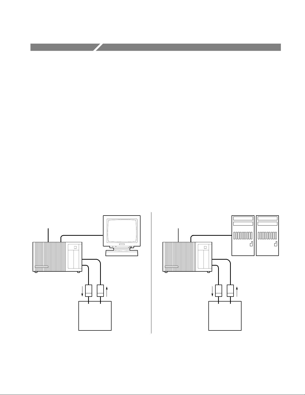
The DAS can be used either as a stand-alone digital analysis system or as an
intelligent peripheral device connected to a host computer or controller.
Figure 1–1 shows two example configurations. On the left, a DAS stand-alone
system (DASXP) is connected to a terminal; on the right, a DAS sends data to a
controlling host computer (DASNT).
Optional Host
Computer
Connection
DAS 9200 Mainframe
Pattern Generation
Data Probe
System
Under Test
Figure 1–1: DAS Basic Configurations
Terminal
Acquisition Data
Probe
Optional Host
Computer
Connection
DAS 9200 Mainframe
Pattern Generation
Data Probe
Host Computer
Acquisition Data
Probe
System
Under Test
DAS 9200 Technician’s Reference
1–1
Page 26

Introduction to DAS Hardware
As a stand-alone system, the DAS can be connected to a Tektronix color
terminal, host computer, printer, or copier. The color terminal displays the
interactive menus. The host computer can be used to transfer acquisition,
stimulation, and instrument setup data to or from the DAS. Various types of
parallel and serial printers are supported to generate non-color (monochrome)
reproductions of display screens and acquisition and pattern-generation data.
Using the optional 92XTerm software (also known as DASNT systems), you can
operate the DAS from a window on a workstation. The interactive menus appear
in the workstation window and are controlled with the mouse and keyboard.
Communication between the DAS and the workstation is over a local area
network (LAN).
As a peripheral device remotely controlled by a host computer, the DAS supports
a Programmatic Command Language (PCL) that is an alternative to the keyboard
and menu interface. PCL commands let you start and stop acquisitions, manage
files, and report status and error information. Data can be processed either by the
DAS or the host computer; when the host computer processes data, the DAS is
the source of raw or partially processed data.
Mainframes and Terminals
The mainframes provide computing power, input and output features, and mass
storage for your modules. The mainframe provides enhanced computing power
due to its larger memory and faster CPU. The mainframes exist in the following
versions:
H DAS 9221 with 16 Mbyte RAM on the Controller board, 100 Mbyte (or
H DAS 9220 with 8 Mbyte RAM on the Memory board, 40 Mbyte hard disk
H DAS 9219 with 2 Mbyte RAM on the Memory board, 20 Mbyte hard disk
The DAS 92E9 is an Expansion mainframe with extra slots for additional modules.
greater) hard disk drive, and 1.4 Mbyte floppy disk drive
drive, and 1.2 Mbyte floppy disk drive
drive, and 400 Kbyte floppy disk drive (the DAS 9219 is no longer
available)
1–2
DAS 9200 Technician’s Reference
Page 27

Introduction to DAS Hardware
Terminals
The standard display device is a Tektronix color terminal with a detachable
keyboard. Earlier versions of the DAS used a 9200T or a 9201T monitor; newer
versions use an X terminal with a detachable keyboard and mouse. Interactive
menus, which are manipulated from the keyboard or mouse, allow you to define the
contents of the system, enter parameters and data, and control the outputs of the
instrument. These menus use color-coded command fields to show the available
selections.
You can power on and power off your mainframe and terminal from a 9200T or
9201T using the terminal power button. This feature is built into DAS 9221
mainframes; for DAS 9219/9220 mainframes, you must install an optional
one-button power-switch adapter.
The 9201T is a direct replacement for the 9200T, so references in this manual to
the 9201T also apply to the 9200T. However, references to the 4205 Service
Manual apply only to the 9201T; if you use a 9200T, refer instead to the 4105
Service Manual.
The X terminal requires a 92LANSE LAN (local area network) module installed
in the mainframe. You can use the X terminal only with the DAS/SE, DASXP, or
DASNT mainframes. For service information, refer to the TekXpress X Terminal
Service Manual.
Mainframe Hardware
The mainframe shown in Figure 1–2 consists of the following major internal components:
H Mechanical chassis
H Controller board (with 16 Mbyte RAM for the DAS 9221)
H Memory board with either 2 Mbyte or 8 Mbyte RAM (DAS 9219/9220)
H Backplane board with 8 module slots
H Hard disk drive
H 3.5 inch or 5.25 inch floppy disk drive
H Three RS-232 ports
H Power supply with a maximum output of 700 watts
DAS 9200 Technician’s Reference
1–3
Page 28
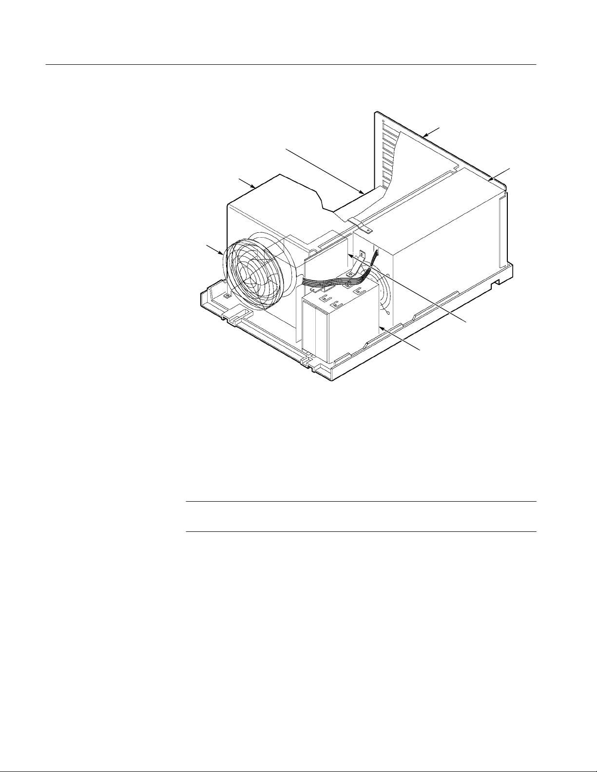
Introduction to DAS Hardware
Card Cage
Fan
RS-232 Ports
(back of Mainframe)
Controller
Board (slot 0)
Power
Supply
Backplane
Board
Hard and
Floppy Disk
Drives
Figure 1–2: Master Mainframe Internal Components (Memory Board in Slot 1 for
DAS 9219/9220)
Mechanical Chassis. The chassis provides the mechanical connection and cooling
for all mainframe components and options. DAS modules reside in the card cage;
probes connect to the modules through openings in the rear of the chassis.
NOTE. To install, remove, or reposition any DAS module, you must remove the
mainframe top cover and card-cage door.
To disassemble major chassis components, refer to Disassembly/Reassembly
Procedures beginning on page 3–3.
Controller Board. The Controller board resides in slot 0 of the Master mainframe;
Expansion mainframes use an Expansion Slave board instead of a Controller
board. The Controller board provides the following resources:
H DAS 9221 mainframes use a 68EC030 microprocessor with address
decoding for an asynchronous bus structure (32-bit address, 32-bit data).
DAS 9219/9220 mainframes use a 68010 microprocessor (24-bit address,
16-bit data).
1–4
DAS 9200 Technician’s Reference
Page 29

Introduction to DAS Hardware
H Nonvolatile RAM for storing interrupt routine addresses, previous shutdown
conditions, and pointers to other processes
H 64 Kbytes of boot ROM in DAS 9221 (32 Kbytes in DAS 9219/9220) for
power-up sequences and diagnostics
H 16 Mbytes of dynamic RAM (DAS 9221 only) with refresh circuitry
H A communication interface between circuit boards, the hard disk drive, and
the floppy disk drive
H Asynchronous time bases and other circuitry supporting the expansion of up
to four time-aligned mainframes
H A clock/calendar with battery backup
H Power-supply control for mainframe shutdown
Memory Board (DAS 9219 and DAS 9220). There are two different Memory boards:
the 2 Mbyte dynamic RAM board is standard with the DAS 9219, and the
8 Mbyte dynamic RAM board is standard with the DAS 9220. The 8 Mbyte
board is also available as a performance upgrade for the DAS 9219. Only one
Memory board can be installed in the Master mainframe, and it must reside in
slot 1; Expansion mainframes do not use a Memory board. (The DAS 9221 has
Memory-board functions resident on the Controller board.) The Memory board
provides the following resources:
H 2 Mbytes of dynamic RAM (standard with the DAS 9219) with refresh
circuitry for supporting system software, post-processing of acquired data,
and other calculations.
H 8 Mbytes of dynamic RAM (standard with the DAS 9220) with refresh
circuitry. The lower part of RAM supports system software and post-proces-
sing of acquired data. The upper part of RAM temporarily stores configura-
tion and data files to improve the system response time.
H Circuitry supporting the Memory Management Unit (MMU), for multiple
process control.
H An interface to the Controller board, allowing access to the system RAM and
to the terminal, host, and auxiliary communication ports.
Backplane Board. This board provides the mechanical and electrical connections
between the Controller board, the Memory board (DAS 9219 and DAS 9220),
and the eight slots used for the acquisition and pattern generation modules.
Signals are carried on bus structures, some of which extend outside the Master
mainframe to Expansion mainframes.
DAS 9200 Technician’s Reference
1–5
Page 30
Introduction to DAS Hardware
Hard and Floppy Disk Drives. The operating system software is installed on the
hard disk, along with other files (such as user-generated setups and reference
memories).
The DAS 9221 mainframes have been available with 100 Mbyte, 127 Mbyte,
170 Mbyte, and 270 Mbyte SCSI hard disk drives. The DAS 9220 mainframes
used 40 Mbyte and 80 Mbyte hard disk drives (ST506 interface), while the
DAS 9219 mainframes had 10 Mbyte and 20 Mbyte hard disk drives. To
determine the size of hard disk in your mainframe, refer to the Diagnostic menu.
An optional 80 Mbyte hard disk drive is available for DAS 9219/9220 mainframes. If data security or portability is a concern, you can order your mainframe
with a removable hard disk drive, so that setup and data files can be secured
overnight or easily transported to another DAS. An 80 Mbyte removable drive is
available for the DAS 9219/9220; a 127 Mbyte, 170 Mbyte, or 270 Mbyte
removable drive is available for the DAS 9221. (Other versions of the removable
hard disk drive were available for earlier versions of the mainframe.)
WARNING. The removable drive for the DAS 9221 (SCSI drive) is not interchangeable with the removable drives for the DAS 9219/9220 (ST506 interface
drives). If you install the wrong type of drive into your mainframe, you can
damage the drive.
Do not disconnect or remove the removable hard disk drive while the mainframe
is powered. Doing so will damage the hard disk or corrupt the file system.
The floppy disk drives are used for loading application software from floppy disk,
copying files for use on other mainframes, and making and restoring backup files.
Backup procedures with on-screen instructions are available. A light on the front of
the floppy disk drive indicates when a floppy disk is being accessed.
A 3.5 inch, 1.4 Mbyte floppy disk drive is standard in DAS 9221 mainframes
with System Software Release 3, Version 1.40 and higher. The floppy disk drive
is also available as an upgrade kit for older systems.
A 5.25 inch, 1.2 Mbyte floppy disk drive was available in earlier versions of the
DAS 9220 and DAS 9221 mainframes. This disk drive is available as an option
for the DAS 9219 mainframe. This drive reads floppy disks written in
360 Kbyte/400 Kbyte format; however, it cannot write to disks of this type. For
write operations, use only 96 TPI (tracks per inch), double-sided, high-density
floppy disks with this drive.
A 5.25 inch, 400 Kbyte floppy disk drive was standard in the DAS 9219
mainframe. This drive can read or write to floppy disks in 360 Kbyte/400 Kbyte
format only. Use only 48 TPI, double-sided, double-density floppy disks with
this drive; do not use 96 TPI high-density disks.
1–6
DAS 9200 Technician’s Reference
Page 31

Introduction to DAS Hardware
RS-232 Ports. The DAS 9219/9220 mainframes have three 25-pin DCE RS-232
ports and the DAS 9221 mainframe has three 9-pin DCE RS-232 ports. Other
devices access these ports through openings on the rear panel. The three ports
have the following functions:
H The terminal port connects the mainframe to a display device. Baud rates are
38400 (default), 19200, 9600, 4800, 2400, 1200, 600, 300, and 110.
H The host port connects the mainframe to a host computer system with a
null-modem cable. Baud rates are 38400, 19200, 9600 (default), 4800, 2400,
1200, 600, 300, and 110.
H The auxiliary port connects the mainframe to other RS-232-compatible
devices (for example, a printer). Baud rates are 38400, 19200,
9600 (default), 4800, 2400, 1200, 600, 300, and 110.
The host and auxiliary ports transmit eight data bits, no parity, and one stop bit. You
can configure the terminal and host port protocol using the Communications menu.
Optional Expansion and I/O Ports. The 92C01, 92C02, and 92C03 GPIB/Expansion modules are optional interface boards for the DAS. These modules function
as follows:
H The 92C01 module provides a GPIB port for the mainframe. (It was
available for earlier versions of the mainframe.)
H The 92C02 module provides a GPIB port and an interface to the DAS 92E9
Expansion mainframe.
H The 92C03 module provides an interface only to the DAS 92E9 Expan-
sion mainframe.
Master mainframes have direct memory access (DMA) capability; this feature is
not available in Expansion mainframes. Therefore, 92C01/02/03 modules must
be installed in slot 8 of the Master mainframe. The GPIB portion of the 92C01
and 92C02 modules does not work in the DAS 92E9 Expansion mainframe;
however, the 92C03 module and the expansion portion of the 92C02 module are
fully functional when installed in slot 8 of the Expansion mainframe. Therefore,
you should use the 92C03 module in Expansion mainframes.
LAN Interfaces. The 92LANSE and 92LAN Modules provide a LAN (local area
network) interface for the DAS mainframe. The 92LANSE module is standard in
a DAS 9221 mainframe used with the X terminals. These modules were optional
in other mainframes. The 92LANSE Module connects directly to the DAS 9221
Controller board and can only be used with DAS 9221 mainframes.
The 92LAN Module is no longer available. For information on the 92LAN
module, refer to the 92LAN User/Installation Manual.
DAS 9200 Technician’s Reference
1–7
Page 32

Introduction to DAS Hardware
Power Supply . The power supply module consists of two boards that supply
power to all mainframe components. This supply can deliver up to 650 watts
from either a 115 V or 230 V AC power source (see Table 1–1 for Master
mainframes and Table 1–2 for Expansion mainframes).
WARNING. To change the line-voltage input of the power supply (between 115 V
and 230 V), refer to Maintenance beginning on page 2–1.
Mainframe Power
Requirements
The DAS mainframes support different numbers of acquisition and pattern-generation modules based on the type of power cord and power supply used with
each mainframe. The standard 12 A power cord should be used for Master
mainframes drawing less than 400 watts (12 A/115 V) and for Expansion
mainframes drawing less than 475 watts. When the module configuration in the
mainframe requires more power, a higher-current power-cord/power-supply
combination must be used (refer to Tables 1–1 and 1–2). If the module configuration in the Master mainframe requires more than 575 watts (650 watts in
Expansion mainframes), the DAS will automatically shut off.
NOTE. If you install the 15 A power cord (Option 1A), put the label supplied with
the power cord on the DAS back panel over the existing description that reads:
1900 VA MAX., FREQ. 48-63 Hz.
The power source must be capable of supplying the maximum line current
required for your system. A mainframe connected to a 115 V power source draws
a maximum continuous current of 15 A; the one-cycle surge current is 25 A
nominal. Therefore, a Master mainframe with three Expansion mainframes may
require a total line current of 60 A. (A mainframe connected to a 230 V power
source draws a maximum continuous current of 10 A, so a Master mainframe
with three Expansion mainframes may require a total line current of 40 A.)
1–8
When the DAS is connected to a 230 V power source, you must use a 230 V
power cord. The DAS draws no more than 10 A when operating at 230 V, but
when the DAS is connected to a 3-phase power source, the mainframe draws no
more than 8 A on any phase. The three-phase power cord is permanently attached
to the power supply. To upgrade your mainframe’s power supply with the
three-phase option, contact your Tektronix field service center.
DAS 9200 Technician’s Reference
Page 33

Introduction to DAS Hardware
Á
Á
Á
Á
Á
Á
Á
Á
T able 1–1: Power for Master Mainframes
Watts Voltage Cord Option Source
400 W
500 W
575 W
БББББ
2
700 W
1
Operation at a low line of 90 V is possible if the card-cage load is reduced to
105 V – 127 V
105 V – 127 V
200 V – 250 V
БББББ
1
200 V – 250 V
(phase-to-phase)
Std.
Opt. 1A
A1 – A5
ÁÁÁÁ
Opt. 1B
(3-phase)
3
115 V, 12 A
115 V, 15 A
230 V, 10 A
БББББ
120/208 V, 8 A
425 watts or less.
2
The 700 W 3-phase power supply option was discontinued as of serial number
B061162.
3
The three-phase load is Y-connected. A maximum of 15 A at three times the
frequency may flow into the neutral conductor. A switch or circuit breaker at the
installation site is required by some international standards.
T able 1–2: Power for Expansion Mainframes
Watts Voltage Cord Option Source
475 W
575 W
650 W
2
750 W
БББББ
1
Operation at a low line of 90 V is possible if the card-cage load is reduced to
425 watts or less.
2
The 750 W 3-phase power supply option was discontinued as of serial number
B061162.
3
The three-phase load is Y-connected. A maximum of 15 A at three times the
frequency may flow into the neutral conductor. A switch or circuit breaker at the
installation site is required by some international standards.
105 V – 127 V
105 V – 127 V
1
200 V – 250 V
200 V – 250 V
(phase-to-phase)
БББББ
Std.
Opt. 1A
A1 – A5
Opt. 1B
(3-phase)
3
ÁÁÁÁ
115 V, 12 A
115 V, 15 A
220 V, 10 A
120/208 V, 8 A
БББББ
Refer to Selecting the Line Voltage and Replacing the Line Fuse beginning on
page 2–6 for instructions on how to change the line voltage.
Module Power Requirements. Each combination of boards requires a different
amount of power from the mainframes. Therefore, you must select a power cord,
power supply, and power source that meets your system line-current demands.
DAS 9200 Technician’s Reference
1–9
Page 34

Introduction to DAS Hardware
Á
Á
To determine the power cord and power source you need, check the message
displayed during power-on that shows the total wattage for the boards installed
in each mainframe. (The power-up message is erased when the system menus
display.) Calculate the total wattage required (from Table 1–3) and compare it
with the available power (from Tables 1–1 and 1–2). If the installed boards
require more power than is available from your current power cord and power
source, then you must upgrade your mainframe to meet those requirements.
NOTE. If you reconfigured the boards in your mainframe since the last powerdown or added boards to your system, check the power values in Tables 1–1,
1–2, and 1–3 to ensure that the total wattage required by the new configuration
can be supplied by your current mainframe power cord and power source.
Table 1–3 lists the power consumed for each board. Use this table to calculate
the power required for your mainframe’s configuration. For example, if your
mainframe contains the following boards: one 92A16, two 92A16Es, one 92S16,
and one 92S32, then the total power required equals: 107 W (A16) + 166 W
(A16Es) + 78 W (S16) + 79 W (S32), or 430 W. Next, compare this value with
the power-cord options in Tables 1–1 and 1–2. Since the standard 12 A power
cord delivers a maximum of 400 watts, the Option 1A power cord must be used
to supply up to 500 watts to the card cage.
T able 1–3: Power for DAS Cards (with Probes)
Card Type Power (watts)
92A16 Master Interface
92A16E Expander Interface
92A96/SD/UD
92A96D/XD
92C96/D/XD/SD
92A60 Controller
92A60/D Memory
92A90 Controller
92A90/D Memory
92S16
92S32
ББББББББ
92SX109
92SX1 18
92C01
92C02
92C03
107
83
1
150
140
1
150
80
50
80
50
78
79
БББББ
78
79
25
30
25
1–10
DAS 9200 Technician’s Reference
Page 35

T able 1–3: Power for DAS Cards (with Probes) (Cont.)
Á
Á
Card Type Power (watts)
Introduction to DAS Hardware
92HS8 Master Interface
92HS8E Standard Interface
92LAN
92V64PM Pattern Master
92V64PE Pattern Expander
92V64E Error Memory
ББББББББ
1
Acquisition Module power requirements reduced to
20
12
25
64
64
64
БББББ
140 W max. effective SN B061162 and above
The DAS software checks your configuration at power on and warns you to use
the correct power source and power cord. The power supply and module cards
can be damaged if you try to operate the DAS in an illegal configuration. The
DAS 9221 Controller board contains a set of jumpers that identify the type of
power cord and power supply in the mainframe. If you change the power cord or
power supply, then you should relocate these jumpers to reflect the new configuration (refer to Jumper J8700 in Figure 4–29 on page 4–68). If the power requirements exceed safe limits, the system shuts down. For example, if you have five
92A96 Modules in one mainframe (700 W, which exceeds the power requirements), the DAS displays a warning message at power-up and then shuts down.
Power Cords. The mainframe has no main AC power switch, so the power cord
serves as the main-power disconnect. The power-cord connection for the Master
mainframe and Expansion mainframe is on the rear panel. The standard power
cord for the mainframe is rated at 12 A; optional power cords are available for
mainframe configurations requiring more power.
The mainframe uses a three-wire power cord with a three-contact plug for
connection to the power source and protective ground. The plug’s protectiveground connects to accessible metal parts of the mainframe.
WARNING. To protect against electrical shock, insert the power-cord plug into a
grounded power source receptacle.
External Event Connections. The optional 92C02 and 92C03 modules provide a
set of pins that support external event I/O signals. For more information, refer to
Using the External Event I/O Pins in the DAS System User Manual.
DAS 9200 Technician’s Reference
1–11
Page 36

Introduction to DAS Hardware
The External Event In pin accepts a TTL-level signal from an external source.
The received event can be monitored by (or can control) other modules. You can
set this up in the Signal Definition overlay (Cluster Setup menu).
The External Event Out pin passes a TTL-level event signal from a DAS to an
external component to use as an arming or triggering signal. For example, the
event-out signal can trigger an oscilloscope or stop, start, or trigger a separate
DAS system.
Discrete I/O Port (DAS 9221 Mainframes with 92LANSE Modules). The optional
92PORT software product allows you to monitor and send signals to a systemunder-test using the 37-pin D-connector on the rear of the Master mainframe.
DAS with Option 04
An option to the DAS mainframe, Option 04, allows the mainframe to satisfy the
German electromagnetic interference (EMI) requirements. Refer to Replaceable
Mechanical Parts serial number history of Option 04 on page 7–24.
DAS Systems Prior to January 1, 1996. DAS mainframes equipped with Option 04
that were sold prior to January 1, 1996 satisfied the German electromagnetic
interference (EMI) requirements VDE 0871, Class B. This VDE option applied
to mainframes set for 230 V operation only; operation at 115 V exceeds
component ratings. A mainframe with Option 04 includes the following items:
H Conductive elastic between the front panel and media mount
H Rear-panel probe shields
H EMI gasket material on the edges of the baseplate
H Clip for holding the power supply tightly against the inside of the rear panel
H Probe clamps for holding probes to the rear panel
H Six grounding clamps for RS-232 connectors (DAS 9219/9220 only)
H Conductive paint on the inside of the top cover and baseplate to make a
connection to the EMI gasket material along the edges of the baseplate
1–12
H Screen material on the front panel and top cover
H EMI gasket material on the inside-rear edge of the top cover
DAS 9200 Technician’s Reference
Page 37

Introduction to DAS Hardware
Follow these precautionary guidelines when using an Option 04-equipped
mainframe:
H Avoid scratching any surface coated with conductive paint.
H Avoid bending or tearing gasket material along the edges of the baseplate
and snagging clothing on gasket material.
H Avoid bending or snagging the EMI gasket material when installing or
removing boards from mainframe slots.
Remove only shields that correspond to probes or cables being attached, because
unnecessary removal of the shields increases EMI radiation. Remove a rear-panel
probe shield as follows:
1. Remove the two top screws.
2. Remove the two screws that attach the adjacent shield.
3. Remove the rear-panel probe shield.
4. Replace the screws attaching the adjacent shield.
To connect to the host port of a DAS 9219/9220 mainframe, you must remove
the corresponding port connector shield.
DAS Systems After January 1, 1996. Newer DAS mainframes with Option 04 meet
Directive 89/336/EEC for electromagnetic compatibility. Option 04 applies to
mainframes set for 230 V operation only; operation at 115 V exceeds component
ratings. A mainframe with Option 04 includes a 230 V line filter to eliminate or
reduce electromagnetic interference.
DAS 9200 Technician’s Reference
1–13
Page 38

Introduction to DAS Hardware
DAS 92E9 Expansion
Mainframe
The DAS 92E9 Expansion mainframe provides additional slot space for
acquisition and pattern generation modules. Up to three Expansion mainframes
can be added to the Master mainframe. A fully-expanded system (Master
mainframe with three Expansion mainframes) provides a total of 28 usable slots.
Expansion and Master mainframes use the same mechanical chassis, backplane,
and power supply. However, the Expansion mainframe does not contain a
Memory board, power switch, or disk drives. In an Expansion mainframe, an
Expansion Slave board replaces the Master mainframe’s Controller board.
If you have one Expansion mainframe with the Master mainframe, you can place
it on top of the Master mainframe, as in Figure 1–3; the Master mainframe can
support the weight of only one Expansion mainframe. When using two or three
Expansion mainframes, all mainframes must be vertically rackmounted; the
Master mainframe must be positioned as the lowest mainframe in the rack. For
complete details on rackmounting, refer to the Option 05: Rackmount Installa-
tion Instructions document.
Acquisition Data Probe
Expansion
Mainframe
Master
Mainframe
Pattern Generation
Data Probe
System Under Test
Figure 1–3: DAS Master Mainframe Connected with One Expansion Mainframe
In a fully-expanded system (see Figure 1–4), the Master mainframe and
Expansion mainframes 1 and 2 require an Expansion board in slot 8 of each
mainframe. The Master mainframe uses either a 92C02 GPIB/Expansion module
or a 92C03 Expansion module to make the connection to the Expansion Slave
board installed in the next mainframe. Expansion mainframes 1 and 2 use a
92C03 module. Refer to Disassembly/Reassembly of the Mainframes beginning
on page 3–3 for module installation and removal instructions.
1–14
DAS 9200 Technician’s Reference
Page 39

Introduction to DAS Hardware
NOTE. The system software numbers the DAS 92E9 Expansion Mainframe slots
from 9-35. You can use these slots, except the Expansion Slave board slot, for
modules.
Expansion Mainframe 3
Slot 35
8 slots for Acquisition and/or
Pattern Generation Modules
Slot 27
Slot 26
Slot 18
Slot 17
Slot 9
Slot 8
Expansion Slave Board
Expansion Cable
Expansion Mainframe 2
Expansion Board
7 slots for Acquisition and/or
Pattern Generation Modules
Expansion Slave Board
Expansion Cable
Expansion Mainframe 1
Expansion Board
7 slots for Acquisition and/or
Pattern Generation Modules
Expansion Slave Board
Expansion Cable
Master Mainframe
Expansion or Exp/GPIB
Figure 1–4: T wenty-Eight Slots Available with One Master and Three Expansion
Mainframes
DAS 9200 Technician’s Reference
Slot 0
6 slots for Acquisition and/or
Pattern Generation Modules
Controller Board
1–15
Page 40

Introduction to DAS Hardware
Á
Á
Á
Á
Á
Á
Á
Á
Á
Á
Acquisition and Pattern Generation Modules
Data acquisition and pattern generation modules, consisting of one or more
printed-circuit boards, are the building blocks of the DAS system. These boards
are installed in mainframe bus slots according to configuration guidelines in the
user manual for each module. Refer to Table 1–4 for a list of available modules.
Brief descriptions of these modules are included in General Circuit Functions.
For detailed information on individual modules, including specifications and
menu and field descriptions, refer to the appropriate user manual.
T able 1–4: DAS Series Acquisition and Pattern Generation Modules
Module Purpose Channels Depth Speed
92A16
acquisition
16
4K
200 MHz
92A16E
1
92A60
1
92A60D
1
92A90
1
92A90D
ÁÁÁ
2
92A96
2
92A96D
92A96XD
92A96SD
92A96UD
2
92C96D
92C96XD
92C96SD
ÁÁÁ
3
92HS8
92HS8E
3
92S16
92S32
acq. expander
acquisition
acquisition
acquisition
acquisition
acquisition
acquisition
2
acquisition
2
acquisition
2
acquisition
acquisition
2
acquisition
2
acquisition
acquisition
acq. expander
pattern generation
pattern generation
ББББББ
ББББББ
16
60
60
90
90
ÁÁÁ
96
96
96
96
96
96
96
96
ÁÁÁ
8
8
16
32
4K
32K
128K
32K
128K
ÁÁÁ
8K
32K
128K
512K
2M
32K
128K
512K
ÁÁÁ
8K
8K
1K
8K
200 MHz
20 MHz
20 MHz
20 MHz
20 MHz
ÁÁÁ
100 MHz
100 MHz
100 MHz
100 MHz
100 MHz
100 MHz
100 MHz
100 MHz
ÁÁÁ
2 GHz
2 GHz
50 MHz
50 MHz
1–16
92SX109
92SX1 18
1
The 92A60/D and 92A90/D are both two-board sets; other modules consist of a single
pattern generation
pattern generation
18
9
2K
16K
100 MHz
100 MHz
board.
2
The 92A96 High-Speed timing offers asynchronous support of 48 channels at
200 MHz and 24 channels at 400 MHz.
3
The 92HS8 has a mainframe cabinet that connects to the DAS through an interface
board.
DAS 9200 Technician’s Reference
Page 41

Introduction to DAS Hardware
You can combine modules functionally in menus. Combining acquisition
modules adds data-channel width (for example, combining 92A16 and 92A16E
boards). Combining pattern generation modules increases pattern memory depth
(for example, combining 92S16 and 92S32 boards). You can also group modules
to operate as an independently functioning unit (called a cluster); several clusters
can run simultaneously. For more information on grouping modules and clusters,
refer to the DAS System User Manual.
DAS 9200 Technician’s Reference
1–17
Page 42

Introduction to DAS Hardware
1–18
DAS 9200 Technician’s Reference
Page 43

Page 44

Page 45

Maintenance
This chapter explains how to keep your DAS mainframe, associated modules, and
terminal in good working condition. It also contains procedures on how to change
the line-voltage selection (between sources of 115 V and 230 V) and replace the
lithium battery on the Controller board of DAS 9219/9220 mainframes.
WARNING. Dangerous electric-shock hazards exist inside the mainframe. Be sure
to power down the mainframe and disconnect the power cord before removing
the cabinet. Only qualified service personnel should disassemble the mainframe.
CAUTION. When powering down the mainframe, wait 60 seconds before
disconnecting the power cord. This allows the mainframe to complete file-management procedures and move the hard disk head to a safe position.
Preventive Maintenance
Static Precautions
Preventive maintenance consists of periodic cleaning. If dust accumulates on
components, it acts as an insulating blanket and prevents efficient heat dissipation. This condition can cause overheating and component breakdown. Periodic
cleaning reduces instrument breakdown and increases reliability.
You should clean the DAS mainframe and terminal as needed, based on the
operating environment.
CAUTION. Many components within the mainframe are extremely susceptible to
static-discharge damage. Service the mainframe only in a static-free environment. Observe standard handling precautions for static-sensitive devices while
servicing the instrument. Always wear a grounded wrist strap, or equivalent,
while servicing the mainframe.
DAS 9200 Technician’s Reference
2–1
Page 46

Maintenance
Observe the following precautions to avoid damage:
H Do not handle static-sensitive components on the boards.
H Transport and store static-sensitive boards in their original containers or on
conductive foam. Label any package that contains static-sensitive assemblies.
H Wear a wrist strap attached to the mainframe while handling the boards to
discharge the static voltage from your body.
H If you need to temporarily set a board down, place it on the card cage to
protect it from damage by static voltage.
H Do not allow anything capable of generating or holding a static charge on the
work surface.
H Do not slide a board over any surface.
H Avoid handling boards in areas that have a floor or work-surface covering
capable of generating a static charge.
Cleaning Guidelines
H When not in use, store boards in a static-free (conductive) package.
Use the following guidelines when cleaning the mainframe and modules:
CAUTION. Spray-wash dirty parts with a cleaning solution (as described in
Interior Cleaning, later in this section), THOROUGHLY RINSE with deionized
water, and IMMEDIATELY DRY with low air pressure.
When cleaning near unsealed electromechanical components, use as little
washing as possible. This prevents removing the lubricant from the components
and getting excess moisture into the contact areas of the switches. MOISTURE
WILL CAUSE CORROSION, which may degrade instrument performance.
DO NOT use a freon-based cleaner on the circuit boards. Freon will damage
aluminum capacitors.
DO NOT wash the Standby/On switch. Cover the switch during washing procedures.
DO NOT use fluorocarbon-based spray cleaners or silicon spray lubricants on
switches or switch contacts. These sprays may damage the circuit-board
material or plastic parts, and leave a dust-collecting residue. Use Tektronix
Contact Lubricant and Cleaner (part number 006-0442-00) as a lubricant.
2–2
To prevent damage from electrical arcing, completely dry all circuit boards,
switches, and board interface connectors. Do this by heating the board or switch
in an oven at 65° C (150° F) for 15 minutes before applying power.
DAS 9200 Technician’s Reference
Page 47

Maintenance
Mainframe
The following paragraphs describe maintenance procedures for DAS mainframes.
Exterior Cleaning. Dust the exterior surfaces of the mainframe with a dry, lint-free
cloth or a soft-bristle brush. If dirt remains, use a cloth or swab dampened with a
75% isopropyl alcohol solution. A swab is also useful for cleaning in narrow spaces
around the controls. Do not use abrasive compounds on any part of the instrument.
CAUTION. To prevent getting moisture inside the instrument during external
cleaning, use only enough liquid to dampen the cloth or swab.
DO NOT use chemical cleaning agents; they may damage the plastics in the
instrument. In particular, avoid chemicals that contain benzene, toluene, xylene,
acetone, or similar solvents.
Interior Cleaning. Clean the interior every six months to keep dust from contaminating the disk drives. To access the mainframe’s interior, refer to the instructions in Disassembly/Reassembly Procedures.
Use a dry, low-velocity stream of air to clean the interior of the mainframe. A
soft-bristle brush is useful for cleaning around components. If a liquid must be
used for minor internal cleaning, use a 75% isopropyl alcohol solution and rinse
with deionized water.
Floppy Disk Drive. The floppy disk drive requires routine maintenance to operate
at maximum efficiency. The disks may be permanently damaged if dirt and dust
accumulate on the recording surfaces. To prevent damage, the disks should be
stored in the envelope and box provided, where they will not be exposed to dust
or dirt. In addition, the head should be cleaned periodically.
You will need the following materials for routine maintenance:
H Vacuum cleaner
H 5.25 inch floppy-disk head-cleaning kit
The routine maintenance and cleaning schedules for the floppy disk drive are as
follows:
H Clean the exterior (face) of the floppy disk drive monthly with a damp cloth
and a 75% isopropyl alcohol solution.
CAUTION. Do not allow moisture to enter the disk drive. When power is applied,
voltages may damage internal components.
DAS 9200 Technician’s Reference
2–3
Page 48

Maintenance
H Clean the head monthly. Use the instructions provided with the head-clean-
ing kit.
H Clean the interior every six months with a soft-bristle brush and vacuum
cleaner.
If the disk drive is heavily used, or is used in a dirty environment, you should
clean the drive more frequently.
Hard Disk Drive. The hard disk drive requires no periodic maintenance.
Terminal and Keyboard
The following paragraphs describe maintenance procedures for the terminal
and keyboard.
Exterior Cleaning. Dust the exterior surfaces of the terminal and keyboard with a
dry, lint-free cloth or a soft-bristle brush. If dirt remains, use a cloth or swab
dampened with a 75% isopropyl alcohol solution. A swab is also useful for
cleaning in narrow spaces around the controls. Do not use abrasive compounds
on any part of these instruments.
CAUTION. To prevent getting moisture inside the instrument during external
cleaning, use only enough liquid to dampen the cloth or swab.
DO NOT use chemical cleaning agents; they may damage the plastics in the
instrument. In particular, avoid chemicals that contain benzene, toluene, xylene,
acetone, or similar solvents.
T erminal Screen. Clean the face of the display screen using a soft cloth dampened
with a solution of 75% isopropyl alcohol.
2–4
Keyboard. Use an artist’s soft brush to remove any dust or foreign matter between
the keypads.
Interior Cleaning. For procedures on disassembly and interior cleaning of the
9200T, refer to the 4105 Service Manual. For procedures on disassembly and
interior cleaning of the 9201T, refer to the 4205 Service Manual. For disassem-
bly and interior cleaning procedures for the X terminals, refer to the TekXpress X
Terminal Series Service Manual. (These manuals are not part of the DAS
documentation package; to obtain a manual, contact your local Tektronix
representative.)
DAS 9200 Technician’s Reference
Page 49

Maintenance
DAS Modules
92HS8/8E Cabinet
The following paragraphs describe cleaning procedures for the DAS modules.
To clean the surface of a DAS module, use a dry, low-velocity stream of air. A
soft natural-bristle brush is useful for cleaning around components. To prevent
static damage to parts, use only a natural-bristle brush (a synthetic brush can
generate static electricity).
CAUTION. Do not use liquid cleaning agents when cleaning the modules.
The following paragraphs describe cleaning procedures for the 92HS8 cabinet.
Exterior Cleaning. Dust the exterior surfaces of the 92HS8/8E cabinet with a dry,
lint-free cloth or a soft-bristle brush. If dirt remains, use a cloth or swab
dampened with a 75% isopropyl alcohol solution. A swab is also useful for
cleaning in narrow spaces around the controls. Do not use abrasive compounds
on any part of the cabinet.
CAUTION. To prevent getting moisture inside the cabinet during external
cleaning, use only enough liquid to dampen the cloth or swab.
DO NOT use chemical cleaning agents; they may damage the plastics in the
instrument. In particular, avoid chemicals that contain benzene, toluene, xylene,
acetone, or similar solvents.
Interior Cleaning. To access the cabinet’s interior, refer to the instructions in
Disassembly/Reassembly Procedures.
Use a dry, low-velocity stream of air to clean the interior of the instrument. A
soft natural-bristle brush is useful for cleaning around components.
CAUTION. Do not clean in areas near a 92HS8/8E hybrid IC or its associated
Hypcon assembly elastomer.
DAS 9200 Technician’s Reference
2–5
Page 50

Maintenance
Corrective Maintenance
Corrective maintenance consists of inspecting the instrument for damage and
obtaining replacement parts. Periodic inspection reduces instrument breakdown.
This section also discusses procedures for changing the line-voltage selection
and replacing the lithium battery on the Controller board.
Inspection
Obtaining Replacements
Inspect the instrument for broken connections, frayed wires, poorly seated
components, leaking capacitors, damaged hardware, and heat-damaged components. Heat damaged parts usually indicate other circuit problems.
If you notice any of the above problems, inform your Tektronix field representative.
Obtain replaceable parts for your instrument from your local Tektronix Field
Office or representative.
Mechanical. Most of the mechanical parts in this instrument are manufactured by
Tektronix. Some parts are selected by Tektronix to satisfy particular requirements, or are manufactured to certain specifications for Tektronix. To determine
the Tektronix part number of a mechanical part, refer to Replaceable Mechanical
Parts beginning on page 7–1.
Electrical. Individual electrical components are not replaceable parts, except fuses
and the lithium battery on the DAS 9219/9220 Controller board. Instead, whole
assemblies are replaced (such as the 92A16 module, 92HS8 cabinet, or 92HS8
interface cable). The part numbers for the assemblies can be found in Replaceable
Electrical Parts. The power supply is replaceable as a unit only. The part number
can also be found in Replaceable Electrical Parts beginning on page 6–1.
Selecting the Line Voltage
and Replacing the Line
Fuse
2–6
DAS Mainframe. To change between the 115 V and 230 V line-voltage selections
on the mainframe, perform the following steps.
CAUTION. A power supply with Option 04 (VDE) should operate at 230 V only,
not at 115 V. Option 04 provides a line filter.
WARNING. Disassembly procedures should be performed only by qualified
service personnel. You may be exposed to dangerous electric-shock hazards if
you remove the cover. Before removing the cover, power down the mainframe,
wait 60 seconds, and then disconnect the power cord. This procedure allows the
power-down sequence to complete.
DAS 9200 Technician’s Reference
Page 51

Maintenance
1. Perform steps 8, 9, 11, 12, and 13 of Procedure 7: Removing the Power
Supply beginning on page 3–15.
2. Remove the three screws holding the power supply frame together, as shown
in Figure 2–1.
Screws (3)
Figure 2–1: Location of Power Supply Frame Screws
3. Gently lower the side of the power supply to expose the inside of the
4. Refer to Figure 2–2 to locate the line voltage selection jacks (J134, J136,
DAS 9200 Technician’s Reference
power supply.
J137, J138, and J139) at the rear of the Primary board in the power supply.
2–7
Page 52

Maintenance
Label
Jacks
Primary Board
W135
J136
J139 J138
Primary Board
Figure 2–2: Location of Line Voltage Selection Jacks
5. Refer to Figure 2–3 to determine the current line selection.
W135
J134
J137
Primary Board
J136
J139 J138
J134
J137
Secondary Board
Secondary Board
8–9 8–0 8–N 8–9 8–0 8–N
J164 J163 J162
115 VAC Operation
Secondary Board
J164 J163
230 VAC Operation
Figure 2–3: Position of Line Voltage Selection Jacks for 115 V or 230 V Operation
NOTE. The numbers 8-9, 8-0, and 8-N in Figure 2–3 indicate the following
wire-color code (resistor color code standard):
H Wire 8-9 is a gray wire with a white stripe.
H Wire 8-0 is a gray wire with a black stripe.
H Wire 8-N is a gray wire with no stripe.
2–8
J162
DAS 9200 Technician’s Reference
Page 53

Maintenance
6. Change the selection by grasping the plastic boot of the wire with needle-
nose pliers and moving the wire to the appropriate jack.
NOTE. When installing W135 on J136 or J134, turn W135 180_to insert it on
the jack.
7. Reassemble the power supply and replace it in the mainframe.
8. Remove the fuse from the back panel (see Figure 2–4 ) and replace the
mainframe fuse as follows:
H 115 V operation uses a 15 A, medium blow fuse.
H 230 V operation uses a 10 A, slow blow fuse.
To determine the fuse part number, refer to Replaceable Electrical Parts.
NOTE. 230 V operation requires one of the power cord Options A1-A5.
Fuse
Power Cord
Connection
Line Voltage
Indictor
Discrete I/O Connector
GPIB Connector
92LANSE
Connectors
RS-232C Port Connectors
Figure 2–4: Location of DAS 9221 Back Panel Fuse and Line V oltage Indicator Knob (DAS 9219/9220 Look Similar)
DAS 9200 Technician’s Reference
2–9
Page 54

Maintenance
9. Loosen the screw in the middle of the line-voltage indicator knob. (Refer to
Figure 2–4.)
10. Turn the knob until you can see the appropriate line voltage in the recessed
portion of the knob.
CAUTION. Check that the indicator shows the correct line voltage. The instrument may be damaged if it is accidentally connected to the wrong power source.
11. Tighten the screw to secure the line voltage indicator.
12. For the DAS 9221, change the power-supply/power-cord configuration
jumper (J8700 on the Controller board) to reflect the new configuration.
13. Reassemble the mainframe.
9200T Terminal. There are two line voltage selection switches on the rear panel of
the 9200T (see Figure 2–5). Before applying power to the terminal, check that
the settings of both switches match the nominal voltage level of the AC power
outlet that will supply power to the terminal.
AC Voltage
Selector Switches
Figure 2–5: Location of AC Voltage Selector Switches on the 9200T
CAUTION. After the 9200T is turned off, wait five seconds to discharge the
capacitors before turning it on again.
To change the line voltage selection on the 9200T, turn off the terminal and
unplug the power cord. Switch the line-voltage selection switches to the desired
position and plug the power cord into the appropriate outlet. (230 V operation
requires one of the power cord Options A1-A5.)
2–10
DAS 9200 Technician’s Reference
Page 55

Maintenance
9201T Terminal. There is one line voltage selection switch on the rear panel of the
9201T. Before applying power, check that the setting of this switch matches the
nominal voltage level of the AC power outlet that will supply power to the
terminal.
CAUTION. After the 9201T is turned off, wait five seconds to discharge the
capacitors before turning it on again.
To change the line voltage selection on the 9201T, turn off the terminal and
unplug the power cord. Switch the line voltage selection switch to the desired
position and plug the power cord into the appropriate outlet. (230 V operation
requires one of the power-cord Options A1-A5.)
X T erminals. There are no line voltage selection for the X terminals. The
terminals automatically adjust to line voltages in the range of 90 to 260 VAC
with the frequency between 48 and 66 Hz. Only use a power cable with the
appropriate power source that is in good condition and complies with the local
certification standards.
92HS8/8E Cabinet. The line voltage selector switch, line fuse, and AC power
switch for the 92HS8 cabinet are located inside the right side panel of the cabinet
(when facing the front of the cabinet). (See Figure 2–6.) The AC power switch
should always be in the on position (switched towards the front of the cabinet).
The line-voltage indicator for the 92HS8 cabinet is located on the left side of the
back panel (see Figure 2–7). A black hex-head screw indicates which voltage
source the cabinet is set to use.
WARNING. Changing the position of the back panel screw does not change the
power supply voltage range. The position of this screw is only an indicator of the
voltage setting.
DAS 9200 Technician’s Reference
2–11
Page 56

Maintenance
Voltage Selector
115 V or 230 V
Fuse
AC Power
Figure 2–6: Location of the Line Voltage Selector and Line Fuse Behind the 92HS8/8E Side Panel
Switch
2–12
DAS 9200 Technician’s Reference
Page 57

Line Voltage
Indicator
Maintenance
Figure 2–7: Back Panel Location of the 92HS8 Line Voltage Indicator Screw
To change the line voltage selector on the 92HS8/8E cabinet between 115 V and
230 V operation, perform the following steps.
1. Power down the DAS mainframe and 92HS8 cabinets and disconnect all
power cords.
2. Facing the rear of the 92HS8 cabinet, remove the corner feet on the top and
bottom of the left side of the cabinet using a TORX screwdriver.
3. Slide the cabinet side out of its holding track to expose the power supply line
fuse and line-selector switch, located near the front of the instrument.
4. Change the line voltage selector, then remove the 92HS8 line fuse and
replace it as follows:
H 115 V operation requires a 5 A, fast blow fuse.
H 230 V operation requires a 2.5 A, fast blow fuse.
NOTE. 230 V operation requires one of the power-cord Options A1-A5.
To determine the part number of these fuses, refer to Replaceable Electrical
Parts.
5. Replace the side panel and corner feet on the cabinet.
DAS 9200 Technician’s Reference
2–13
Page 58

Maintenance
6. Remove the line-voltage indicator screw on the back panel and position it to
indicate the power source being used.
Replacing the Battery on
the DAS 9219/9220
Controller Board
The DAS 9219 and DAS 9220 mainframes use a lithium backup battery on the
Controller board when there is no power to the mainframe (such as when the
power cord is not attached). This battery also provides backup power for the
clock/calendar feature displayed in the Diagnostic menu.
CAUTION. Battery replacement should be performed by a qualified technician.
NOTE. The DAS 9221 battery is built into the circuitry and has a 10-year life. To
replace this battery, a qualified service technician must replace a chip on the
Controller board.
If your mainframe is in constant use, you should check the battery yearly. If it is
not used for long periods, you should check the battery every six months.
Replace the backup battery if the voltage is near 2.6 volts, since the system
information stored in RAM may be lost if the voltage drops below this value.
To determine the condition of the battery, measure the battery voltage across the
battery (BT905 in Figure 2–8) with the line cord removed from the power
supply. When it becomes necessary to replace the backup battery on the
Controller board, use the following procedure:
2–14
CAUTION. After powering down the mainframe, wait 60 seconds before disconnecting the power cord to allow the mainframe to lock the head in the hard disk
drive and complete file-management procedures.
1. Remove the line cord from the power supply.
2. To provide temporary power to the Controller board circuits while replacing
the battery, connect an external +5 volt supply across C921 (shown in
Figure 2–8).
CAUTION. Before connecting the external power supply, observe the polarity of
the supply and the capacitor. Connect the minus (–) lead of the supply to the
grounded side of the capacitor.
DAS 9200 Technician’s Reference
Page 59

Controller Board
C921
+–
Maintenance
U731
U918
– BT905 +
U928U925
Figure 2–8: Location of C921 on Mainframe Controller Board
3. Remove the battery (BT905 in Figure 2–8) by cutting the elastic band and
pulling the battery out of the holder.
WARNING. To avoid injury, observe proper procedures for handling and disposal of
lithium batteries. Improper handling may cause fire, explosion, or severe burns.
Don’t recharge, crush, disassemble, heat the battery above 100_ C (212_ F),
incinerate, or expose the contents of the battery to water. Dispose of the battery in
accordance with local, state, and national regulations. For further information,
refer to the Lithium Battery Disposal section following this procedure.
4. Place the new battery in position and push it into the holder, while observing
the correct polarity.
5. Disconnect the external +5 volt power supply.
6. Install a new elastic band around the battery by performing the following
7. Check the condition of the battery by measuring the voltage across it. It
DAS 9200 Technician’s Reference
substeps:
a. Perform steps 2, 7, and 8, of Procedure 8: Removing the Card Cage
beginning on page 3–18 in the Disassembly/Reassembly Proce-
dures chapter.
b. Gently pull the card-cage assembly up from the nylon posts.
c. Insert the elastic band into the holes provided. Pull the elastic band
tightly, from the bottom, with needle-nose pliers.
d. Reinstall the card-cage assembly.
should measure approximately 3 volts.
2–15
Page 60

Maintenance
Disposing the Lithium
Battery
You can safely dispose of small quantities of batteries (less than 20) with
ordinary garbage in a sanitary landfill; larger quantities must be sent by surface
transport to a Hazardous Waste Disposal Facility. The batteries should be
individually packaged to prevent shorting and packed in a sturdy container that is
clearly labeled “Lithium Batteries — DO NOT OPEN.”
2–16
DAS 9200 Technician’s Reference
Page 61

Page 62

Page 63

Disassembly/Reassembly Procedures
This chapter describes the disassembly and reassembly procedures for the DAS
mainframes, 92HS8 cabinet, and acquisition and pattern generation module probes.
In the following procedures, directional terms (top, bottom, left, right, front, and
back) assume that your mainframe is in an upright position (with the bottom
down), and that you are facing the front of the mainframe. Reassembly procedures are the reverse of the disassembly procedures unless otherwise noted.
Figure 3–1 shows the DAS mainframe; use this figure to locate the major
components. The DAS 92E9 Expansion mainframe is very similar to the DAS.
In the disassembly procedures, differences between these mainframes are noted.
Controller
Board (slot 0)
Card Cage
RS-232 Ports
(back of Mainframe)
Power
Supply
Fan
Backplane
Board
Hard and
Floppy Disk
Drives
Figure 3–1: DAS Mainframe Internal Components (Memory Board in Slot 1 for
DAS 9219/9220)
In addition to the illustrations in this section, refer to Replaceable Mechanical
Parts for a detailed exploded view and parts list for the mainframes.
DAS 9200 Technician’s Reference
3–1
Page 64

Disassembly/Reassembly Procedures
General Precautions
Observe the following precautions when performing any disassembly/reassembly
procedures.
CAUTION. After powering down the mainframe with the Standby/On switch, wait
60 seconds before disconnecting the power cord. This allows the mainframe to
lock the head in the hard disk drive to a safe position and complete file-management procedures.
H DO NOT attempt any disassembly procedure with the power cord connected.
H DO NOT operate a mainframe or 92HS8 cabinet with the cover removed to
H DO NOT attempt mainframe disassembly procedures with probes installed
H DO NOT place the mainframe on its front face. The front panel will not
prevent overheating.
or RS-232 connections in place.
support the weight of the mainframe.
Tools Required
The following list identifies the tools necessary for disassembly of the DAS
mainframes, 92HS8 cabinet, and probes. This is a complete list of tools; you will
need only the tools for your specific disassembly needs.
3
H
H
inch flexible shaft nutdriver
16
1
inch nutdriver
4
H 11 inch (shaft length) #2 POZIDRIV screwdriver (magnetic tip)
1
inch flat-blade screwdriver
H
8
H #1 POZIDRIV screwdriver
H #1 Phillips screwdriver
H Torque screwdriver with the following tips:
1
inch slotted blade tip
8
1
inch nutdriver tip
4
#1 Phillips tip
TORX-type magnetic tip (T-20)
3–2
DAS 9200 Technician’s Reference
Page 65

H #0 Phillips screwdriver
H Small diagonal cutters
H Two board ejector tools (located inside the mainframe front panel) (Tektro-
nix part number 105-0985-00)
Disassembly/Reassembly of the Mainframes
The following procedures describe how to disassemble and reassemble the DAS
Master mainframe and DAS 92E9 Expansion mainframe. The user may
perform procedures 1 and 2. However, qualified service personnel must
perform the other procedures.
CAUTION. Only qualified service personnel should perform disassembly
procedures. Dangerous electric-shock hazards may be exposed when you remove
the mainframe cover. Power down the mainframe and wait 60 seconds before
disconnecting the power cord, so the power-down sequence completes.
Disassembly/Reassembly Procedures
Procedure 1:
Removing the Mainframe
Top Cover
To install or remove a module, you must first remove the mainframe’s top cover
and inner card-cage door. Use the following steps to remove the top cover.
1. Power down the mainframe.
CAUTION. After powering down the mainframe, wait 60 seconds before disconnecting the power cord. This allows the head in the hard disk drive to lock in a
safe position and the software to complete file-management procedures.
2. Disconnect the power cord.
3. Press the plastic latches on the left and right lower-rear sides of the cover and
lift the cover from the back (see Figure 3–2).
DAS 9200 Technician’s Reference
3–3
Page 66

Disassembly/Reassembly Procedures
Press
Lift
Figure 3–2: Removing the Mainframe T op Cover
4. Tilt the cover off the front of the mainframe. Set the cover aside so its inner
surface will not be scratched.
Instructions for removing the card-cage door are listed in procedure 2.
3–4
DAS 9200 Technician’s Reference
Page 67

Disassembly/Reassembly Procedures
Procedure 2:
Removing a Module From
the Card Cage
This procedure describes how to remove an acquisition or pattern generation
module from the mainframe card cage. It can also be used to remove other
boards (such as the Memory board in DAS 9219/9220 mainframes or GPIB/Expansion modules) that reside in reserved slots of the mainframe.
CAUTION. Many components within the mainframe are susceptible to
static-discharge damage. Follow the standard handling precautions for
static-sensitive devices under Static Precautions beginning on page 2–1 when
servicing this instrument.
1. Perform procedure 1 on page 3–3.
2. To remove the card-cage door, unscrew (counterclockwise) the fasteners on
the card-cage door (see Figure 3–3). Remove the door and set aside.
Ejector Tools
Fastener
Terminal Post Connector
Figure 3–3: Ejector T ools and Location of Card-Cage Door Fasteners
3. Disconnect the probes, GPIB, and LAN cables from the rear of the main-
frame. For DAS 9219/9220 mainframes, disconnect the RS-232 connections.
4. Remove the connectors from the GPIB and LAN modules (if installed).
DAS 9200 Technician’s Reference
Fastener
Card-Cage Door
3–5
Page 68

Disassembly/Reassembly Procedures
NOTE. When removing a 92A60 or 92A90 module, remove the 92A60/90 Memory
board before removing the buffer probe attached to the 92A60/90 Controller
board.
5. Insert the two board-ejector tools into the board you are removing, as shown
NOTE. Board-ejector tools are stored inside the front panel of the mainframe on
the left-hand side.
6. Pry the board from the backplane.
CAUTION. Pry with even force on both sides of the board to prevent bending the
backplane-alignment pins.
7. Grasp the sides of the board and pull it out of the card cage.
in Figure 3–3.
Procedure 2a:
Removing the 92LANSE
Module
Procedure 3:
Removing the Front Panel
When installing modules, align the connection between the backplane and the
module before applying pressure; this prevents connector damage.
1. Perform procedures 1 on page 3–3 and 2 on page 3–5 to remove all other
boards or modules from the mainframe.
2. Unscrew the five screws holding the 92LANSE module to the Controller
board.
3. Carefully lift the 92LANSE module and remove the three cables connected
to the module.
1. Perform procedure 1 on page 3–3.
2. Note the orientation of the connector(s) at the back of the Standby/On switch
and disconnect the connector(s) from the switch.
3. Place the mainframe so the bottom of the front panel hangs over the
workbench.
4. Press the release latches located underneath the front panel, as shown in
Figure 3–4. While pressing the latches, pull the front panel towards you.
5. Move the mainframe back onto the workbench.
3–6
DAS 9200 Technician’s Reference
Page 69

Latch
(Underneath)
Disassembly/Reassembly Procedures
Figure 3–4: Location of Latches for Removing the Front Panel
Procedure 4:
Removing the Fan
1. Perform procedures 1 on page 3–3 and 3 on page 3–6.
2. Disconnect the two-wire power cable (W865) located on top of the fan.
3. Disconnect the three-wire sense cable connector (W866) located below the
power cable.
4. Remove the four screws that hold the fan to the card cage; they are located at
the 4, 6, 8, and 12 o’clock positions.
5. Pull the fan and fan cage towards you and off the mainframe.
When reinstalling the fan, do not allow the ribbon cables or wires to hang in
front of the fan. Torque the four screws that hold the fan to the card cage 5.0 to
6.0 inch pounds.
Latch
DAS 9200 Technician’s Reference
3–7
Page 70

Disassembly/Reassembly Procedures
Procedure 5:
Removing the Media
Frame
This procedure describes how to remove the media frame from the DAS mainframe.
CAUTION. If your system has a removable media hard disk drive, remove it before
disassembly to prevent damage.
1. Perform procedures 1 on page 3–3 and 3 on page 3–6.
2. Remove the ribbon cables connected to the Controller board beneath the
card-cage fan. For DAS 9219 and DAS 9220 mainframes, remove the three
ribbon cables (W298, W398, and W698) connected to J298, J398, and J698 on
the Controller board. For DAS 9221 mainframes, remove the two ribbon cables
(W3900 and W6900) connected to J3900 and J6900 on the Controller board.
3. Using care not to cut the power-supply wires, cut the plastic tie that holds the
power-supply wires to the top of the media frame.
4. Remove the stabilizer bracket connecting the media frame to the power-sup-
ply frame.
5. Unscrew the four screws that hold the media frame to the mainframe
baseplate (see Figure 3–5).
6. Grasp the media frame with both hands and tilt it outward, then lift up and
remove. You may need to open the cable clamp located on the left side of
the media frame before you can move the media frame onto the adjacent
work surface.
7. Remove the ribbon cable W965 that connects the power supply to the media.
3–8
DAS 9200 Technician’s Reference
Page 71

Disassembly/Reassembly Procedures
Stabilizer
Bracket
Screws (6)
Procedure 6:
Removing the Disk Drives
From the Media Frame
Figure 3–5: Location of Screws for Removing the Media Frame
This procedure describes how to remove both the hard disk and floppy disk drives
from your media frame. This procedure does not apply to Expansion mainframes.
1. Perform procedure 5 on page 3–8.
2. Disconnect the ribbon cable(s) from the drive being removed.
3. Remove the two screws (on top of the appropriate drive) from the media frame.
4. Gently turn the media frame on its side, to prevent damage, and remove the
two bottom screws.
5. Grasp the drive from the front and pull towards you to remove it from the
media frame.
Installation Hints for Floppy Disk Drives. The procedure for installing the floppy
disk drive is essentially the reverse of the disassembly procedure. When installing
the floppy disk drive, torque the metric screws from 5.0 to 7.0 inch pounds.
DAS 9200 Technician’s Reference
3–9
Page 72

Disassembly/Reassembly Procedures
CAUTION. Some disk drives use metric screws, identified by their gold finish.
Make sure metric screws are used only into metric mounting holes to prevent
damaging the threads.
Installation Hints for Fixed-Media Hard Disk Drives. The procedure for installing
the fixed-media hard disk drive is essentially the reverse of the disassembly
procedure.
1. Attach the data and controller cables to the floppy disk drive and hard-disk
2. Secure the ribbon cables in the self-adhesive retaining clamp.
3. Connect the power cable to both disk drives (power-cable connectors are
connectors. Figures 3–6 and 3–7 show the correct connector and cable
arrangements for the different mainframes.
keyed to the connectors on the disk drives). Use between 7.5 and 10.0 inchpounds of torque to fasten the media frame.
CAUTION. Be careful not to pinch any power or ribbon cables when installing the
media frame.
4. Reconnect the cables to the mainframe Controller board, routing the
cables so they do not block the airflow from either the card-cage fan or the
power-supply fan. The ribbon cables must be folded neatly, as shown in
Figure 3–8 on page 3–13.
5. Secure the power-supply wires to the top of the media frame using a cable tie.
3–10
DAS 9200 Technician’s Reference
Page 73

Floppy Disk Data
Cable (red line on top)
Floppy Disk Drive
Power connector
Disassembly/Reassembly Procedures
Hard Disk Data
Cables (red line
on top)
Hard Disk Power
Connector
Figure 3–6: T ypical Cable Connections for Fixed-Mount Hard and Floppy Disk
Drives for DAS 9219 and DAS 9220 Mainframes
DAS 9200 Technician’s Reference
3–11
Page 74

Disassembly/Reassembly Procedures
Hard Disk Power
Floppy Disk
Data Cable (red
line on top)
Hard Disk Data
Cables (red line
on bottom)
Floppy Disk Drive
Power connector
Connector
Figure 3–7: T ypical Cable Connections for Fixed-Mount Hard and Floppy Disk
Drives For DAS 9221 Mainframes
Installation Hints For Removable-Media Hard Disk Drives. The procedure for
installing the removable-media hard disk drive is essentially the reverse of the
disassembly procedure.
CAUTION. DO NOT install a DAS 9221 removable SCSI disk drive into a
DAS 9219 or DAS 9220 mainframe that uses removable ST506 drives. Installing
the wrong type of drive into a system may result in damage to the hardware.
Refer to Hard and Floppy Disk Drive Switch and Jumper Positions in
Troubleshooting for descriptions of the drives.
1. Before installing the new media frame, test the fit of the removable hard disk
drive. (See Figures 3–9 on page 3–14 and 3–10 on page 3–15 for the
different mainframes.) The disk drive should fit snugly into place with only a
small amount of friction from the media frame.
3–12
DAS 9200 Technician’s Reference
Page 75

Disassembly/Reassembly Procedures
After you are satisfied with the fit, remove the hard disk drive before installing
the media frame in the DAS.
Floppy Disk
Ribbon Cable
Hard Disk
Cable
Figure 3–8: Folding the Ribbon Cables
If you have a DAS 9221 mainframe, fold the cables as shown in the left side of
the illustration. If you have a DAS 9219/9220 mainframe, fold the cables as
shown on the right side of the illustration.
2. Attach the data and controller cables to the floppy disk drive and hard-disk
3. Secure the ribbon cables in the retaining clamp.
4. Connect the power cable to both disk drives (power-cable connectors are
Floppy Disk
Ribbon Cable
Hard Disk
Cable
connectors. Figures 3–6 and 3–7 show the correct connector and cable
arrangements for each mainframe.
keyed to the connectors on the disk drives). Install the media frame into the
DAS, gently forcing it as far to the right as possible. Use 7.5 to 10.0 inchpounds of torque to fasten the media frame in place.
DAS 9200 Technician’s Reference
3–13
Page 76

Disassembly/Reassembly Procedures
CAUTION. Be careful not to pinch any power or ribbon cables when installing the
media frame.
5. Reconnect the cables to the mainframe Controller board, routing the cables so
6. Secure the power-supply wires to the top of the media frame using a cable tie.
7. Install the stabilizer bracket that secures the media frame to the power-
8. Install the removable media after you complete all reassembly.
that they do not block the airflow from either the card-cage fan or the powersupply fan. The ribbon cables must be folded neatly, as shown in Figure 3–8.
supply frame.
3–14
Figure 3–9: Removable 20 Mbyte Drive in DAS 9219/9220 Media Frame
DAS 9200 Technician’s Reference
Page 77

Disassembly/Reassembly Procedures
Procedure 7:
Removing the Power
Supply
Figure 3–10: Removable Hard Disk Drive in a Media Frame
The hard disk drive is installed on the right side in a DAS 9221 mainframe.
1. Perform procedures 1 on page 3–3 and 3 on page 3–6.
2. Trace the wires from the front of the power supply to the three front-edge
connectors (J690, J590, and J390) on the Backplane board.
3. Using care not to cut the power-supply wires, cut the plastic tie that holds the
power-supply wires to the media frame.
4. Unscrew and disconnect the 21 power-supply wires from the three edge
connectors on the Backplane board.
5. Disconnect the ribbon cable (W290) from J290 on the Backplane board.
6. Disconnect the two-prong power cable connector (W865) and the three-
prong sense cable connector (W866) from the fan.
DAS 9200 Technician’s Reference
3–15
Page 78

Disassembly/Reassembly Procedures
NOTE. Remove the media frame before removing the power supply. It is not
necessary to remove the cables connected to the media for this procedure.
7. Unscrew the four screws that hold the media frame to the mainframe
8. Remove the stabilizer bracket connecting the media frame to the power-sup-
9. Remove the bracket connecting the power-supply frame to the card cage.
10. Grasp the media frame with both hands and tilt it outward, then lift up and
11. Remove the ribbon cable (W965) that connects the power supply to the media.
12. Unscrew the two bottom-front and two top-rear screws of the power-supply
baseplate (see Figure 3–5 on page 3–9).
ply frame.
turn 90° to remove.
frame from the mainframe. (See Figure 3–11.)
Screws (5)
Figure 3–11: Location of Screws for Removing the Mainframe Power Supply
CAUTION. Do not bend the pins on the back of the Backplane board when
removing or installing the power supply.
3–16
DAS 9200 Technician’s Reference
Page 79

Disassembly/Reassembly Procedures
Á
Á
Á
Á
13. Slide the power supply toward the front of the mainframe, tilt it outward,
then lift the power supply out of the mainframe.
Refer to Table 3–1 when reconnecting the power-supply wires to the Backplane board.
T able 3–1: Power-supply Connections
Connector Connector Slot # Wire Color Voltage
J690
1, 2
red
+17.5 V
J690
J690
БББББ
J590
J390
1
All white wires are +5 V; connect these wires to any slot.
2
All black wires are ground; connect these wires to any slot.
3, 4
5 – 7
БББББ
1 – 7
1 – 7
violet
yellow
ÁÁÁÁ
any white
any black
1
2
–17.5 V
+3V
БББББ
+5V
GND
CAUTION. When reconnecting cables, align ribbon cable W290 with J290 on the
Backplane board. If the connectors are offset, the power supply may be damaged.
When reinstalling the power-supply frame into the mainframe, perform the
following procedure:
1. Press the power-supply frame against the rear of the mainframe; check that
there is not a gap between the two frames.
2. Screw the two bottom-front screws of the power-supply frame to the
mainframe; apply between 3.5 and 4.0 inch-pounds of torque to the screws.
3. Screw the two top-rear screws of the power-supply frame to the mainframe;
apply between 3.5 and 4.0 inch-pounds of torque to the screws.
4. Check that the cables do not block the fans.
These steps maximize the air flow between the power-supply frame and the
media frame and reduce EMI radiation.
DAS 9200 Technician’s Reference
3–17
Page 80

Disassembly/Reassembly Procedures
Procedure 8:
Removing the Card Cage
NOTE. You must remove the card cage from the mainframe before removing the
Controller board and the backplane.
1. Perform procedure 1 on page 3–3, procedures 2 and 2a on page 3–6, and
procedure 3 on page 3–6.
2. Disconnect the connectors to the GPIB, 92LAN, or 92LANSE boards. For
DAS 9221 mainframes, disconnect the three internal RS-232 cables from the
Controller board.
3. Remove the stabilizer bracket connecting the power-supply frame to the
card cage.
4. Disconnect the power cable connector (W865) and the sense cable connector
(W866) from the fan.
5. Disconnect W290 from J290 on the Backplane board.
6. Disconnect the ribbon cables located below the fan.
7. Unscrew and remove the 21 power-supply wires from the three connectors
on the Backplane board.
8. Remove the four screws from the back panel, as shown in Figure 3–12.
3–18
Screws (4)
Figure 3–12: Back Panel Screw Locations for Removing the Card Cage
DAS 9200 Technician’s Reference
Page 81

Disassembly/Reassembly Procedures
9. Remove the two bottom-front screws, as shown in Figure 3–13.
Screws (2)
Figure 3–13: Bottom-front Screw Locations for Removing the Card Cage
10. Pull the card cage up from the nylon posts in the baseplate, then forward. Be
careful not to damage the internal RS-232 cables in the DAS 9221.
NOTE. You may need to pinch together the nylon supports on the Controller
board to separate it from the baseplate of the mechanical chassis.
When reconnecting the power-supply wires, torque the screws on the connector
from 3.5 to 4.0 inch-pounds. Align each nylon support with its mounting hole
before pressing the Controller board onto the baseplate.
DAS 9200 Technician’s Reference
3–19
Page 82

Disassembly/Reassembly Procedures
Procedure 9:
Removing the Controller
Board
Preform the following procedure to remove the Controller board from the
master mainframe.
CAUTION. Many components within the mainframe are extremely susceptible to
static-discharge damage. Follow the standard handling precautions for
static-sensitive devices in Maintenance when servicing this instrument.
1. Perform procedure 1 on page 3–3, procedure 2 on page 3–5, procedure 3
on page 3–6, and procedure 8 on page 3–18.
2. Place the card cage upside down, so the bottom of the Controller board
faces up.
3. Remove the seven screws holding the Controller board to the card-cage
assembly.
4. Carefully push the Controller board from the backplane connection with one
hand, while holding the card cage with the other hand.
When reinstalling the Controller board, check that its connections to the backplane
are fully mated. Remember to reconnect any cables that were disconnected during
disassembly, such as the RS-232 cables in the DAS 9221 mainframe.
Procedure 10:
Removing and
Disassembling the
Expansion Cable
(DAS 92E9 only)
The first part of this procedure explains how to remove the expansion cable from
the mainframe.
1. With the power cord disconnected, perform procedure 1 on page 3–3.
2. Using procedure 2 on page 3–5, remove the boards from slots 1 and 2 to
access the Expansion Slave board.
3. Note the orientation and location of the connectors, then unplug the six cables
of the expansion-cable assembly. Refer to the cabling diagram for the
DAS 92E9 Expansion mainframe (Figure 5–7 on page 5–14) during
reassembly.
4. At the rear of the mainframe, remove the three screws from the top of the
strain-relief bracket; they hold together the two parts of the bracket for the
expansion-cable assembly. Then remove the fourth screw that holds the
strain-relief bracket to the mainframe back panel.
5. Note the orientation of the strain-relief bracket components, then remove them.
Remove the expansion-cable assembly from the Expansion mainframe.
6. To remove the end of the expansion-cable assembly that is connected to a
92C02/03 module, remove the two screws holding the expansion-cable
assembly to the DAS L-shaped retaining bracket.
3–20
DAS 9200 Technician’s Reference
Page 83

Disassembly/Reassembly Procedures
The remaining steps describe how to disassemble the expansion-cable assembly.
7. Remove the three screws from the top of the expansion-cable assembly.
8. Remove the top cover to access the cables and board within the housing.
9. To remove the bottom cover, turn the housing face down and remove two
screws. (For reassembly, separate these smaller-size screws from the others.)
10. To remove the expansion-cable board from the housing, turn the housing
face up and remove the two screws holding the board to the bottom cover.
Tip the board up on one side and remove it from the housing, being careful
not to damage any cables.
Procedure 11:
Removing the Expansion
Slave Board (DAS 92E9
only)
The Expansion mainframes do not have a Controller board; instead, they have an
Expansion Slave board. Perform the following procedure for removing the
Expansion Slave board from the Expansion mainframe.
CAUTION. Many components within the mainframe are extremely susceptible to
static-discharge damage. Follow the standard handling precautions for
static-sensitive devices in Maintenance when servicing this instrument.
1. Perform procedure 1 on page 3–3, procedure 2 on page 3–5, procedure 3
on page 3–6, and procedure 10 on page 3–20.
NOTE. You may need to pinch together the nylon supports on the Expansion
Slave board to separate it from the bottom cover of the mechanical chassis.
2. Perform procedure 8 on page 3–18 to remove the card cage from the
mainframe. Place the card cage upside down, so the bottom of the Expansion
Slave board faces up.
3. Remove the seven screws holding the Expansion Slave board to the
card-cage assembly.
4. Carefully push the Expansion Slave board from the backplane connection
When reinstalling the Expansion Slave board, check that its connector to the
backplane are fully mated. Check that all cables are connected as in the
DAS 92E9 cabling diagram (see Figure 5–7 on page 5–14).
DAS 9200 Technician’s Reference
with one hand, while holding the card cage with the other hand.
3–21
Page 84

Disassembly/Reassembly Procedures
Procedure 12:
Removing the Backplane
1. Perform procedure 1 on page 3–3, procedure 2 on page 3–5, procedure 3
on page 3–6, procedure 8 on page 3–18, and procedure 9 on page 3–20.
2. Place the left side of the card-cage assembly on the work surface.
3. Remove the five screws holding the Backplane board to the card cage.
4. Remove the plastic shield from the front of the Back plane board.
5. Separate the connection between the Backplane board and the Controller
board and then lift the Backplane board off the card-cage assembly.
When reconnecting the power-supply wires to the Backplane board, refer to
Table 3–1 on page 3–17. The screws must be torqued between 3.5 and 4.0 inchpounds.
Disassembly/Reassembly of the 92HS8 Cabinet
The following procedures describe the partial disassembly of the 92HS8 cabinet,
such as:
H Removing the 92HS8 top, bottom, and side covers
H Elevating the Memory board to access the Acquisition board
H Removing the power supply and cooling fans
H Replacing 92HS8 probes connected to the cabinet
Reassembly procedures, unless otherwise noted, are the reverse of the disassembly procedures.
The procedure for removing a 92HS8 Interface board from the DAS is similar to
removing any DAS module.
WARNING. The interior of the 92HS8 cabinet contains hazardous voltages.
Before removing the covers, power down the unit and disconnect the AC power
cord from the rear of the cabinet.
CAUTION. When reassembling the 92HS8, fold the cables to maximize the flow of
cooling air over the hybrids. Restricted air flow may cause the hybrids to
overheat.
3–22
DAS 9200 Technician’s Reference
Page 85

Disassembly/Reassembly Procedures
Procedure 1:
Removing the 92HS8
Cabinet Covers
Procedure 2:
Elevating the 92HS8
Memory Board
This procedure describes how to remove the cabinet top, bottom, and two side
covers. To remove any cover, you will need a screwdriver with a TORX-type tip.
NOTE. Operating the cabinet for extended periods without covers may cause the
instrument to overheat.
1. Disconnect the power cord from the 92HS8 cabinet.
2. Check that all cabling does not interfere with the cover being removed.
3. Remove the top cover by removing the two top corner feet at the rear of the
cabinet. Then slide the top cover to the rear and remove it from the cabinet.
4. Remove the bottom cover by removing the two bottom corner feet at the rear
of the cabinet and sliding the bottom cover to the rear of the cabinet.
5. Remove a side cover by removing the top and bottom corner feet from the
rear of the cabinet for the side (left or right) being removed. Slide the side
cover to the rear of the cabinet.
Perform this procedure to access the components under the Memory board.
1. Perform Procedure 1.
2. Remove the seven screws holding the board in place (see Figure 3–14).
3. Swing the Memory board to the upright position, since the board is secured
to the cabinet by a hinge on the left side of the cabinet.
NOTE. You may need to prop the board in the upright position.
DAS 9200 Technician’s Reference
3–23
Page 86

Disassembly/Reassembly Procedures
Memory Board
Screws (7)
Procedure 3:
Removing the 92HS8
Power Supply
Procedure 4:
Removing the 92HS8
Cooling Fans
Figure 3–14: Location of Screws for Elevating the 92HS8 Memory Board
1. Perform Procedures 1 and 2 on page 3–23.
2. Remove the AC power cord (inside the cabinet) from the power supply.
3. Remove the two screws from the top cover of the power supply and remove
the cover.
4. Remove the six screws and the two spacer posts that secure the power supply
to the cabinet (see Figure 3–15). Tip the power supply onto its side.
5. Unsolder the cables from the back of the power supply and remove it from
the cabinet.
The following procedure applies to the three fans in the 92HS8 cabinet.
1. Perform Procedures 1 and 2 on page 3–23 and steps 1-3 of procedure 3. Tip
the power supply to gain access to the necessary screws. Note: Do not
unsolder the wires to the power supply and remove it, unless you cannot
access the screws for fan removal.
2. Disconnect the fan’s power cable.
3–24
3. Remove the screws and nuts from each corner of the fan housing and remove
the fan.
DAS 9200 Technician’s Reference
Page 87

Disassembly/Reassembly Procedures
Procedure 5:
Replacing 92HS8 Probes
Probes must be installed from the inside of the instrument and pulled through to
the outside. Use the following procedure when removing and installing probes.
1. Remove the cabinet’s top cover and lift the Memory board, using procedures
1 and 2 on page 3–23.
2. To remove a probe, remove the probe ground clamp and carefully disconnect
the leads from the SMB and harmonica connectors on the Acquisition board.
While compressing the probe’s boot, pull the probe through the back panel to
the inside of the cabinet.
3. Feed the replacement probe through the back panel from the inside of the
cabinet. Check that the probe’s strain relief is correctly seated in the back panel.
4. Dress the probe wires carefully so that the shields do not contact the chassis
(probe shields are +5 volts).
5. Check that the red coax connects to the +SMB connector and the black coax
connects to the -SMB connector.
6. Check that pin 1 on the three-wide harmonica connector is correctly oriented
with pin 1 on the socket.
7. After probe replacement, recalibrate the 92HS8 using the deskew procedures
described in the 92HS8/8E Module User Manual.
DAS 9200 Technician’s Reference
3–25
Page 88

Disassembly/Reassembly Procedures
Fan
Heat Sink
Power Supply Cover Screws
Screw
Screw
Screw
Power Supply Board
Screw
Screw
Posts (2)
Screw
Figure 3–15: Location of Screws for Removing the 92HS8 Power Supply
Disassembly/Reassembly of Probes
The circuit-board assemblies in each DAS probe are replaceable. The following
procedures describe how to disassemble and reassemble each probe, so you can
replace the assemblies.
CAUTION. Static discharge may damage the probe semiconductors. Follow the
standard handling precautions for static-sensitive devices under Static Precau-
tions on page 2–1 when servicing the probes.
Voltage Selector
Power Cord Plug
AC Power Switch
3–26
DAS 9200 Technician’s Reference
Page 89

Disassembly/Reassembly Procedures
P6461/E Data Acquisition
Probe
P6460 Data Acquisition
Probe
1. Press the latches located on the sides of the P6461 probe.
2. Grasp the top and bottom halves of the probe and pull apart.
3. Remove the static shield.
4. If you need to remove one or more of the podlets, grasp the podlet by the
base, close to the pins, and pull the podlet from the sockets on the board.
5. Disconnect the cable from the board by grasping the pin connector from each
side and pulling the connection apart.
6. Remove the board from the case.
Reassembly of the probe is the reverse of the disassembly procedure. When
reassembling the probe, start with the labeled half of the case facing down. Then,
insert the board.
1. Unscrew the screws in each corner of the probe case.
2. Grasp the top and bottom halves of the probe and pull apart.
3. Lift the hybrid circuit-board assembly from the probe case.
4. Disconnect the cable from the board by grasping the pin connector from each
side and pulling the connection apart.
P6464 Pattern Generator
Probe
Reassembly of the probe is the reverse of the disassembly procedure.
Use the following steps to disassemble the P6464 probe.
CAUTION. When disassembling the probe, avoid contaminating the contacts of
the hybrid circuit and its socket with dust, finger oil, etc.
1. With a flat-blade screwdriver, press the latches on the side of the P6464 probe.
2. Grasp the top and bottom halves of the probe and pull apart.
3. If you need to remove one or more of the podlets, grasp the podlet by the
base, close to the pins, and pull the podlet from the socket on the board.
4. Using a POZIDRIV screwdriver, unscrew the four screws holding the heat
sink to the hybrid.
5. Lift the heat sink and the plate underneath to expose the hybrid.
6. Disconnect the three-wide cable from J160 on the main board and J120 on
the +3 V supply board.
Reassembly of the probe is the reverse of the disassembly procedure.
DAS 9200 Technician’s Reference
3–27
Page 90

Disassembly/Reassembly Procedures
NOTE. Main-board replacements do not contain the hybrid circuit. Retain the
hybrid for use in the replacement board.
P6465 Pattern Generator
Probe
Use the following steps to disassemble the P6465 probe.
NOTE. When disassembling the probe, avoid contaminating the contacts of the
hybrid circuit and its socket with dust, finger oil, etc.
1. With a flat-blade screwdriver, press the latches on the side of the P6465 probe.
2. Grasp the top and bottom halves of the probe and pull apart.
3. If you need to remove one or more of the podlets, grasp the podlet by the
base, close to the pins, and pull the podlet from the socket on the board.
4. Using a POZIDRIV screwdriver, unscrew the three screws on the top of
the plate.
5. Disconnect the two ribbon cables from the top board (Strobe board) and pull
the side of the board out.
6. Unscrew the four screws in the recessed portion of the plate.
7. Lift the plate and remove it from the main board.
8. Disconnect the cable from the board by grasping the pin connector from each
side and pulling the connection apart.
3–28
P6463/A Pattern
Generator Probe
Reassembly of the probe is the reverse of the disassembly procedure.
Use the following steps to disassemble the P6463 or P6463A probe.
1. With a flat-blade screw driver, unlatch the latches on the side of the
P6463/A probe.
2. Remove the upper half of the probe housing and set it aside.
3. To remove the ID/Logic board (the smaller board), unscrew the four
mounting screws with a POZIDRIV screwdriver. Unplug the ID/Logic board
from the Buffer/Driver board by gently pulling the two boards apart.
CAUTION. The ID/Logic board is connected to the pod ID switch through a
two-wire cable. Take care not to stress the cable’s connections during disassembly procedures. Unnecessary strain on the cable may cause damage to the cable.
DAS 9200 Technician’s Reference
Page 91

Disassembly/Reassembly Procedures
4. If necessary, free the pod ID switch from the lower probe housing by slightly
loosening the mounting nut and lifting the switch out.
5. To remove the Buffer/Driver board, gently pull up on the red and black
power leads to free them from the lower probe housing. Grasp the board and
lift it from the lower probe housing. To disconnect the cable assembly from
the Buffer/Driver board, grasp the cable assembly plug and gently pull it
straight out (note pin 1 orientation for reassembly).
6. Reassembly of the probe is the reverse of this procedure.
92A60/90 Buffer Probe
Use the following steps to disassemble the 92A60/90 Buffer Probe.
CAUTION. Static discharge may damage the probe semiconductors. Follow the
standard handling precautions for static-sensitive devices in Maintenance when
servicing this instrument.
1. With the DAS mainframe power OFF, disconnect the lead set or probe
adapter plugged into the probe.
2. With a flat-blade screwdriver, unlatch one side of the probe. Keep that side
slightly separated while unlatching the other side of the probe.
3. Grasp the top and bottom halves of the probe and pull apart.
4. Remove the flat-ribbon cables by grasping the loose tabs and pulling
straight up.
5. Unscrew the two screws holding the circuit board to the bottom plastic case.
They are located near the probe adapter end.
6. Pull the circuit board forward and out.
Reassembly of the probe is the reverse of the disassembly procedure.
Terminals
DAS 9200 Technician’s Reference
The disassembly/reassembly procedures and other helpful service information for
the DAS terminals are found in one of the following documents:
H 9200T: 4105 Service Manual
H 9201T: 4205 Service Manual
H X Terminals: TekXpress X Terminal Series Service Manual
These manuals are not part of the DAS documentation package. Contact your
Tektronix representative to order one of these manuals.
3–29
Page 92

Disassembly/Reassembly Procedures
3–30
DAS 9200 Technician’s Reference
Page 93

Page 94

Page 95

Troubleshooting
This chapter contains troubleshooting information for isolating failures in the
DAS mainframe to the module or board level. This troubleshooting information
includes diagnostics descriptions and troubleshooting tips for areas not tested by
the diagnostics. Terminal diagnostics are also included; refer to the 4105 Service
Manual for additional information on the 9200T, the 4205 Service Manual for
additional information on the 9201T, and the TekXpress X Terminal Service
Manual for additional information on the X terminals. (These manuals are not
part of the DAS documentation package; to obtain them, contact your local
Tektronix representative.)
Mainframe Troubleshooting Overview
Use the following steps as an overview of troubleshooting the mainframes.
1. Ensure that all mainframe modules are correctly and installed and that all
interconnects and cables are properly connected and fully seated. Ensure that
the module installation conforms with all slot location restrictions and
module configuration guidelines.
2. Power up the mainframe and check that the power-supply voltages are within
specification. Also check that the media power-supply voltages are at the
media power connectors.
3. If the power supply does not power up, check the following:
H Power-supply AC-line fuse
H Line-voltage selection
H The AC-line power-cord connection
H Power-supply secondary wiring and control cable connections
H Front-panel DC power switch connection and operation
4. Verify that you properly connected the terminal to the mainframe Terminal
port with the recommended RS-232 cable. Check that the terminal communication parameters (such as baud rate) match the settings of the mainframe.
Also check for the proper setting of the Controller board DIP switches for
the Terminal port near the back of the mainframe.
5. Power up the DAS with DIP switch 1 in the up position (normal boot) and
check the back-panel LED indicators to ensure that no level 0 diagnostic
errors have occurred.
DAS 9200 Technician’s Reference
4–1
Page 96

Troubleshooting
6. Power on the DAS to the BOOT?> prompt (DIP switch 1 in the down
position) and run the System Software File System Check and Verify hard-disk
maintenance utilities. These floppy-based utilities check if the drive is properly
formatted and if the system software is installed and uncorrupted.
7. Check if the Expansion mainframes are properly connected to the 92C02/03
Expansion board in the top slot of the next lower mainframe.
8. Check the following for all mainframes and expansion mainframes:
H Power cord/power supply configuration for the AC-line power being
used
H The AC-line fuses
H Power-configuration jumper on the Controller board (for DAS 9221
mainframes)
Module Troubleshooting Overview
Use the following steps as an overview of troubleshooting the modules; detailed
troubleshooting information is included later in this section.
1. Check that the module is properly installed according to the module
installation instructions. The installation must meet all slot-location
restrictions for the module and adjacent modules. Refer to the installation
section of the module user manual for detailed installation guidelines.
2. If the module fails the power-up diagnostics, check the description for the
four-digit error code from the Diagnostics menu. If the module has a
functional failure, check all connections between the DAS and the system
under test (SUT).
3. Check that the boards are fully seated into the backplane slot connectors. If
necessary, power down the DAS, remove the module, reseat it, and power up
the system. Verify that all probes and cables are fully seated.
4. If the module still fails, check if the problem is slot-related. Power down the
DAS, install the failing module into a different mainframe slot, and power
up the system. This will isolate mainframe slot-related problems.
5. Remove the module and inspect it for physical damage or shorted leads or
components.
6. Replace the module with a known-good replacement module. Check that the
replacement passes its diagnostic tests.
4–2
DAS 9200 Technician’s Reference
Page 97

Troubleshooting
7. If the module still has a problem, try the following procedure:
a. Run the file system Check and Verify utilities to check if the problem is
due to corrupted system software.
b. Remove all modules except the failing module to check if another
module is interfering with the system bus. If the module no longer fails,
reinstall the modules one-by-one to identify the cause of the problem.
c. Check that the DAS power-supply voltages are within specification.
Refer to Introduction to DAS Hardware for the allowable range of the
power-supply voltages.
d. Inspect the 540-pin connectors on the backplane for damaged, bent, or
shorted pins.
e. Replace the Controller board with a known-good board to check the
controller bus interface.
f. If the module is in an Expansion mainframe, check that the Expansion
mainframe cable assembly is properly connected to the 92C02/03
Expansion board in the top slot of the next lower mainframe. Check the
cable assembly for damage and ensure the individual cables are properly
connected. If possible, move the module to the Master mainframe to
verify the failure still occurs.
Power-On Diagnostics
9200T Terminal
Diagnostics
The mainframe and terminal contain diagnostics that normally run when
powered on. Since the terminal provides the user interface, it should be powered
on and checked first (with the mainframe power off). After the terminal
diagnostics complete, turn on the mainframe to execute its power on diagnostics.
Refer to the section DAS Mainframe Diagnostics on page 4–15 for a description
of these diagnostic tests.
Two levels of diagnostics check the 9200T; they are the Power-Up Self Test and
Extended Self Test. Before powering up the terminal, connect the keyboard to
the terminal.
NOTE. The DAS must not be powered on while the terminal diagnostics are
performed, so the 9200T can control the keyboard.
DAS 9200 Technician’s Reference
4–3
Page 98

Troubleshooting
Power-Up Self T est. The Power-Up Self Test runs automatically every time you
turn on the terminal or press the RESET button (see Figure 4–1). This test
checks the keyboard and the display circuitry in the 9200T. The test starts when
you turn on (or reset) the terminal and ends when the cursor appears; it takes less
than 15 seconds to run.
Self Test
Button
Reset
Button
Figure 4–1: Location of SELF TEST and RESET Buttons on the 9200T Rear Panel
During the test, the light in the Caps Lock key (located in the lower-left corner of
the keyboard) flashes once. If the keyboard test fails, the light stays on and the
terminal beeps twice. A message may also appear on the screen.
If the display test fails, the terminal displays a message and beeps twice. If a
message does not appear, adjust the BRIGHTNESS knob (located on the front of
the terminal). If a message still does not appear, refer to the 4105 Service Manual.
If the Power-up Self Test does not detect any errors, the terminal displays a
blinking underscore cursor when the test completes. If the test detects an error,
follow these procedures:
1. Turn the terminal off and wait 15 seconds, then turn it back on. If the test
does not detect any errors, the terminal is operating normally.
2. If a Power-up Self Test error occurs on the second power-up, note the
message on the screen and do the following:
H If the message says “Keyboard Failure” or “Not Attached,” check the
keyboard cable connection on the rear of the terminal.
H If the message says “Nonvolatile Parameters Failure – Defaults Reset,”
you may need to reset some operating parameters. Refer to the 4105
Service Manual.
4–4
DAS 9200 Technician’s Reference
Page 99

Troubleshooting
H If other messages appear, refer to the 4105 Service Manual.
Extended Self Test. The Extended Self Test consists of the Power-Up Self Test and
several tests of the circuitry. It may take up to four minutes to complete. Initiate the
test by pressing the SELF TEST and RESET buttons (see Figure 4–1) as follows:
1. Press SELF TEST and hold it in while you press and release RESET.
2. Hold in SELF TEST for another two seconds, and then release it.
A white crosshair cursor blinks on the screen while the Extended Self Test is
running. After a few seconds, the terminal beeps once and the crosshair is
replaced by the following menu:
Press a function key to do the following:
F6 Exits the Extended Self Test and displays the Adjustment Procedures menu. For
more information, refer to the 4105 Service Manual.
F7 Continues the Extended Self Test.
F8 Exits the Extended Self Test.
If you do not press a key within 20 seconds after the menu appears, the Extended
Self Test continues. When continuing the test, the crosshair blinks intermittently
on the screen. If the test does not detect any errors after approximately two
minutes, the crosshair disappears and the Adjustment Procedures menu appears.
Press function key F8 to return the underscore cursor to the screen.
NOTE. The 4105 Service Manual is not part of the DAS documentation package;
to obtain this manual, contact your Tektronix representative.
DAS 9200 Technician’s Reference
4–5
Page 100

Troubleshooting
9201T Terminal
Diagnostics
Three levels of diagnostics check the 9201T terminal: the Power-Up Self Test,
Main Self Test, and Extended Self Test. Before powering up the terminal,
connect the keyboard to the terminal.
NOTE. The DAS must not be powered on while the terminal diagnostics are
performed, so the 9201T can control the keyboard.
Power-Up Self T est. The Power-Up Self Test runs when you turn on the terminal
or press the RESET button (see Figure 4–2). This test checks the keyboard and
the display circuitry in the 9201T.
During the keyboard test, the light in the Caps Lock key blinks once and then
stays off. If the keyboard test fails, the light stays on. A message may also appear
on the screen.
If the terminal fails the test, it displays a message and beeps twice. If the
terminal beeps twice and a message does not appear, adjust the BRIGHTNESS
knob (located on the front panel).
If Power-up Self Test does not detect any errors, the terminal displays an underline
or block cursor when the test completes. If the test detects an error, the terminal lists
the error below “Self Test Error.” If an error occurs, follow these procedures:
1. Press the RESET button on the front of the terminal to rerun the Power-up
Self Test. If the test does not detect any errors, the terminal is operating
normally.
2. If an error occurs during the second Power-Up Self Test, note the message on
the screen and do the following:
H If the message says “Keyboard Self Test failed,” check the keyboard
cable connection on the front of the terminal.
H If the message says “Nonvolatile Parameters Load” and “Parameters
reset to factory defaults,” you may need to reset some operating
parameters. Refer to the Tektronix 4205 Service Manual. (This manual is
not part of the DAS documentation package; to obtain this manual,
contact your Tektronix representative.)
If the error does not affect the operation of the DAS, you can use the terminal.
For example, if the copier port fails (and that port is not needed), the terminal
can be used until the problem is fixed.
4–6
DAS 9200 Technician’s Reference
 Loading...