

Tektronix DAS-800 Series Users Guide

cover.frm Black I
DAS-800 Series
User’s Guide

titlepgfrm Black 1
DAS-800 Series
User’s Guide
Revision A - December 1993
Part Number: 85790

noticep.frm Black I
The information contained in this manual is believed to be accurate and reliable. However, the
manufacturer assumes no responsibility for its use; nor for any infringements or patents or other rights
of third parties that may result from its use. No license is granted by implication or otherwise under any
patent rights of the manufacturer.
THE MANUFACTURER SHALL NOT BE LIABLE FOR ANY SPECIAL, INCIDENTAL, OR
CONSEQUENTIAL DAMAGES RELATED TO THE USE OF THIS PRODUCT. THIS PRODUCT
IS NOT DESIGNED WITH COMPONENTS OF A LEVEL OF RELIABILITY THAT IS SUITED
FOR USE IN LIFE SUPPORT OR CRITICAL APPLICATIONS.
All brand and product names are trademarks or registered trademarks of their respective companies,
0 Copyright Keithley Instruments, Inc., 1993.
All rights reserved. Reproduction or adaptation of any part of this documentation beyond that permitted
by Section 117 of the 1976 United States Copyright Act without permission of the Copyright owner is
unlawful.
+b
800ug.toc Black iii
+b
Table of Contents
Preface
1 Overview
Supporting Software . . . . . . . . . . . . .
Accessories
2 Functional Description
Analog Input Features ..............
Channel Configuration ...........
Input Configuration ...........
Gains and Ranges. ............
Channel Selection ............
Channel Expansion ...........
Conversion Clock Sources ........
Triggers. ......................
Gates .........................
Data Transfer. ..................
Digital I/O Features ................
8254 Counternimer Circuity ........
Interrupts ........................
Power ...........................
........
........
.......
.......
.......
.......
.......
.......
.......
.......
.......
.......
.......
.......
.......
.......
. . . . l-2
. . . . 1-4
. ...2-2
. ...2-3
. ...2-3
. . . .2-4
. ...2-5
. ...2-6
. ...2-8
. ..2-12
. ..2-14
. ..2-16
. ..2-17
. ..2-17
. ..2-25
. ..2-26
3 Setup and Installation
Installing the Software. ...............................
Installing the DAS-800 Series Standard Software Package . .3-5
Installing the ASO- Software Package
DOS Installation. ...............................
Windows Installation ............................
Unpacking the Board. ................................
Configuring the Board. ...............................
Creating a Configuration File.
Setting the Base Address ...........................
Setting the Input Contiguration ......................
Setting the Interrupt Level .........................
Installing the Board .................................
.3-4
.............. .3-6
.3-6
.3-7
.3-8
.3-8
....................... .3-9
.3-13
.3-16
.3-17
.3-19
iii

800ug.toc Black iv
4
Cabling and Wiring
Attaching Accessory and Expansion Boards.
Attaching an STC-37 Screw Terminal Connector
Attaching an STA-08 / STA-OSPGA Screw Terminal
Accessory. .....................................
Attaching an EXP-16 or EXP-16/A Expansion Board.
Attaching an EXP-GP Expansion Board
Attaching an MB Series Backplane ...................
Connecting Multiple Expansion Boards.
Connecting Signals ..................................
Connecting an Analog Input Signal to a Single-Ended Input. 4-9
Connecting an Analog Input Signal to a Differential Input .4-10
Connecting Digital Signals, ........................
Connecting Counter/Timer I/O Signals
Synchronizing Conversions on Multiple Boards
5
The Control Panel
..............
........ .4-3
...............
...............
...............
........ .4-13
.4-l
.4-4
.... .4-5
.4-6
.4-7
.4-7
.4-9
.4-12
.4-12
6 Calibration
Equipment Required
Potentiometers
Calibration Utility
7
Troubleshooting
Problem Isolation
Troubleshooting Table.
Technical Support
A
Specifications
B
Connector Pin Assignments
............................
.................................
..............................
...............................
..........................
..............................
c DAS-800 Series External Driver
Running the DAS-800 Series External Driver. . . . . . .
Accessing the DAS-800 Series External Driver
Special Characteristics.. . . . . . . . . . . . .
Pseudo-Digital Output: Extended Functions. . . . .
Analog Triggers
Data Formats . . . . . . . . . . . . .
Using Expansion
Board
Gains . . . .
.,6-l
.6-2
.6-4
.,7-l
. . l-2
. l-4
.c-2
.c-2
.c-3
. .c-3
.C-6
.c-9
.c-11
iv
800ug.toc Black v
Software Interrupt Vectors ......................
Counter/Iimer Functions .......................
Error Messages. .................................
II
Keithley Memory Manager
Installing and Setting Up the KMM.
Using
KMMSETUP.EXE
Using a Text Editor.
.......................
...........................
.................
Removing the KMM .............................
Index
List of Figures
Figure 2-l. DAS-800 Series Functional Block Diagram
Figure 2-2. Channel Expansion
...................
Figure 2-3. Initiating Conversions .................
Figure 2-4. Initiating Conversions with a Hardware
Trigger
Figure 2-5. Hardware Gate.
.............................
......................
Figure 2-6. Pulse on Terminal Count Mode. .........
Figure 2-7. Programmable One-Shot Mode. .........
Figure 2-8. Rate Generator Mode.
.................
Figure 2-9. Square-Wave Generator Mode ..........
Figure 2- 10. Software-Triggered Strobe Mode ........
Figure 2-l 1
Figure 3-l.
Figure 3-2.
Figure 3-3.
Figure 3-4.
Figure 3-5.
Figure 4-l.
Figure 4-2.
Hardware-Triggered Strobe Mode. .......... .2-24
DAS-800 Board. ......................... .3-2
DAS-Sol/802 Board ...................... .3-3
Setting the Base Address. ................. .3-14
Setting the Input Configuration. ............ .3-17
Setting the Interrupt Level. ................ ,3-18
Main I/O Connector on a DAS-800 Board ..... .4-2
Main I/O Connector on a DAS-801 or
DAS-802 Board. ......................... .4-3
Figure 4-3.
Attaching an STC-37 Screw Terminal
Connector. .............................. .4-4
Figure 4-4.
Attaching an STA-08 / STA-OSPGA Screw
Terminal Accessory. ...................... .4-5
Figure 4-5.
Attaching an EXP-16 or EXP-16/A Expansion
Board .................................. .4-6
Figure 4-6.
Figure 4-7.
Attaching an EXP-GP Expansion Board. ...... .4-7
Connecting Multiple Expansion Boards ....... .4-8
.c-12
.c-12
.c-13
. D-2
D-2
. D-3
D-4
. .2-2
. .2-l
.2-10
.2-13
.2-15
,2-19
.2-20
.2-21
.2-22
.2-23
800ug.toc Black vi
Figure 4-8.
Figure 4-9.
Single-Ended Input , . . . . . . . . . . . . .4-10
Differential Input. . . . . . . . . . . .4-l 1
Figure 4-10. Synchronizing Conversions on Multiple
Boards . . . . . . , . . . . . . . . . . . . .4-13
Figure 4-l 1.
Figure 6-l.
Figure 6-2.
Figure B-l.
Figure B-2.
Figure C-l.
Figure C-2.
Figure C-3.
List of Tables
Table 2-1.
Table 2-2.
Table 2-3.
Dividing the Rate of the Master Clock .4-14
Potentiometers (DAS-800) . . . . . . . . . .6-3
Potentiometers (DAS-801 / DAS-802) . .6-3
Main I/O Connector (DAS-800) . . . . .B-2
Main I/O Connector @AS-801 / DAS-802) . . .B-5
Analog Trigger Conditions . . .C-7
Using a Hysteresis Value. . , . . . . . .C-8
Initiating Conversions with an Analog Trigger. . .C-9
Supported Gains .........................
Sources for 8254 Documentation
...........
Expansion Board / Backplane Power
Limitations .............................
Table 3-1.
Table 3-2.
Table 3-3.
Table 7-1.
Table A- 1.
Default Configuration
I/O Address Map (OOOH to 3FFH)
....................
..........
Interrupt Levels .........................
Troubleshooting Information.
...............
DAS-800, DAS-801, and DA.%802
Specifications. ...........................
Table B-l.
Main I/O Connector Pm Assignments for the
DAS-SOO................................B- 3
Table B-2.
Table C- 1.
Table C-2.
Table C-3.
Main I/O Connector Pin Assignments for the
DAS-801 /DAS-802
Pseudo-Digital Output Channels
......................
.............
Interrupt Vectors ........................
Error/Status Codes
.......................
.2-4
.2-25
.2-27
.3-10
.3-14
.3-18
.7-2
A- 1
.B-6
.C-4
.C-12
.C-13
vi
preface.frm Black vii
f@
Preface
The DAM00 Series User’s Guide provides the information needed to set
up, install, and use DAS-800 Series boards.
The manual is intended for data acquisition system designers, engineers,
technicians, scientists, and other users responsible for setting up, cabling,
and wiring signals to DA,%800 Series boards. It is assumed that users are
familiar with
application.
data
acquisition principles and with their particular
The
DAS-BOO Series
Chapter 1 provides an overview of the features of DA%800 Series
boards, including a description of supported software and accessories.
Chapter 2 provides a more detailed description of the analog input,
digital I/O, and counter/timer I/O features of DAS-800 Series boards.
Chapter 3 describes how to unpack, configure, and install DAS-800
Series boards.
Chapter 4 describes how to attach accessory and expansion boards
and how to wire signals to DAS-800 Series boards.
Chapter 5 describes how to use the Control Panel to test the functions
of DAS-800 Series boards.
Chapter 6 describes how to calibrate DAS-800 Series boards.
Chapter 7 provides troubleshooting information.
Appendix A lists the specifications for DAS-800 Series boards.
User’s Guide is organized as follows:
vii
preface.frm Black viii
. Appendix B lists the connector pin assignments.
. Appendix C describes how to use the DAS-800 Series External
Driver. The DAS-800 Series External Driver allows you to use
DAS-800 Series boards with certain data acquisition and analysis
software packages.
. Appendix D describes the Keithley Memory Manager. The Keithley
Memory Manager allows you to allocate sufficient memory when
running under Windowsm.
An index completes this manual.
Throughout the manual, keep the following in mind:
. References to DAS-800 Series boards apply to the DAS-800,
DAS-801, and DAS-802 boards. When a feature applies to a
particular board, that board’s name is used.
. References to Microsoft@ QuickBasic” apply to both Microsoft
QuickBASIC (Version 4.0) and Microsoft QuickBasic (Version 4.5).

chapOl_.frm Black 1
Overview
The DAS-800 Series is a family of analog input and digital input and
output (I/O) boards for an IBM@ PC/XTTM, AT’ or compatible computer.
The DAS-80 Series includes the DAS-800, DAS-801, and DAS-802
boards, The major features of DAS-800 Series boards are as follows:
Eight analog input channels (single-ended on the DAS-800;
single-ended or differential on the DAS-801 and DAS-802).
Fixed f5 V analog input range for the DAS-800; nine unipolar and
bipolar, software-selectable analog input ranges for the DAS-801 and
DAS-802.
On-board 8254 counter/timer circuitry, which you can use as a
hardware internal clock source and/or for general-purpose
counter/timer I/O operations.
Software-selectable conversion clock source.
Digital trigger.
Hardware gate.
Four-word FIFO to store converted data: overrun detection logic to
detect lost dam points.
Software-selectable interrupt source.
Three bits of digital input.
. Four bits of digital output.
l-1
chapOl_.frm Black 2
Note:
DAS-800 boards are enhancements of DAS-8 boards; DAS-801
boards are enhancements of DAS-8 PGA boards; DAS-802 boards are
enhancements of DAS-8 PGA/G2 boards. You can use application
programs written to support the DAS-8 with the DAS-800, application
programs written to support the DAS-8 PGA with the DAS-801, and
application programs written to support the DAS-8 PGA/GZ with the
DAS-802.
Supporting Software
You can use DAS-800 Series boards with the following software:
DASJOO Series standard software package
DAS-800 Series boards. Includes function libraries for writing
application programs under DOS in a high-level
Microsoft QuickBasic and Microsoft Visual BasicTM for DOS, support
files, utility programs, and language-specific example programs.
Refer to
more information.
the DAM00 Series Function Call Driver User’s Guide
- Shipped with
language
such as
for
l-2
ASO-
software package - The optional Advanced Software
Option for DAS-800 Series boards. Includes function libraries for
writing application programs under Windows and DOS in a
high-level language such as Borland@ C/C++, Borland Turbo Pascal@
for DOS and Windows, and Microsoft Visual Basic for Windows;
support files; utility programs; and language-specific example
programs. Refer to the
Guide
for more information.
DA&800 Series utilities
DA&BOO Series Function Cull Driver User’s
- The following utilities are provided as part
of both the DAS-800 Series standard software package and the
ASO- software package:
-
Confgurarion urilify
-The configuration utility (D800CFG.EXE)
allows you to create or modify a configuration tile. The
configuration tile indicates the settings of switches and jumpers
on the board and provides other configuration information. This
information is used by the DAS-800 Series Function Call Driver
and other software packages to perform the board’s I/O
Overview

chapOl_.frm Black 3
operations. Refer to page 3-9 for more information about the
configuration utility.
-
Control Panel
-The Control Panel allows you to perform
operations on DAS-800 Series boards, without programming. It
provides a quick way to test your board and monitor
your I/O
operation. Two versions of the Control Panel are available:
CTL800.EXE (for DOS) and CTLBOOW.EXE (for Windows).
Refer to Chapter 5 for more information about the Control Panel.
-
Calibrafion uriliry
- The calibration utility (CALSOO.EXE) allows
you to calibrate the analog input circuitry of DAS-800 Series
boards. Refer to Chapter 6 for more information about the
calibration utility.
. DAM300 Series custom controls
programs in Visual Basic for Windows. Refer to the
Custom
. Data acquisition and analysis application software -
Controls User’s Guide
- Help you to write application
VisualDAS
for more information.
Many
menu-driven, integrated software packages are available for
DAS-800 Series boards, including VIEWDAC?, EASYEST LXa’,
and EASYEST AGW. In addition, programming tools, such as the
ASYST@ scientific and engineering programming
language, are
available to help you customize your own application program.
Note:
If you use VIBWDAC!, EASYEST LX / AG, or ASYST to
program your DAS-800 Series board, you must use the DA&800
Series External Driver, which is shipped as part of the DAS-800
Series standard software package. Refer to Appendix C for
information on using the DAS-800 Series External Driver.
. DAS-800 Series register I/O map - If you cannot satisfy your
application’s requirements with the available software packages and
you are an experienced programmer, you may be able to program
your DAS-800 Series
board
through direct register I/O instructions.
Contact the factory for more information.
I-3

chapOl_.frm
Accessories
Black 4
The following accessories are available for use with DAS-800 Series
boards:
. STC-37 screw terminal connector - For
all DAS-800 Series boards,
provides 37 screw terminals that allow you to access the functions of
the board; connects directly to the DAS-800 Series board without a
cable.
l
STA-08 screw terminal accessory - For the DAS-800 board
provides screw terminals that allow you to access the functions of the
board; provides a breadboard area with power and additional screw
terminals to access the user-designed circuitry.
. STA-08PGA screw terminal accessory
- For the DAS-801 and
DAS-802 boards only, provides screw terminals that allow you to
access the functions of the
board;
provides a breadboard area with
power and additional screw terminals to access the user-designed
circuitry.
. EXP-16 and EXP-16/A expansion boards
- Sixteen-channel
multiplexer and signal-conditioning expansion boards; provide cold
junction compensation (CJC) for thermocouples and
switch-selectable gains ranging from 0.5 to 2000.
. EXP-GP expansion board
- An 8-channel signal-conditioning
expansion board; connects to RTDs, thermistors, strain gages, and
other variable resistance sensors; provides CJC for thermocouples
and switch-selectable gains of 1, 10, 100, and 1000 or 2.5.25.250,
and 2500.
only,
1-4
. MB Series modules and backplanes
- MB Series modules are
high-performance, signal-conditioning modules that measure
thermocouple, RTD, strain gage, voltage, and current inputs and are
installed in MB Series backplanes. MB Series backplanes provide
screw terminals for connecting the high-level analog I/O signals.
Overview
chapOl_.frm Black 5
. STA-SCM8
screw terminal accessory - Allows you to
connect a
DAS-800 Series board to up to four MB-02 backplanes; provides
screw terminals that allow you to access the functions of the board;
provides a breadboard area with power for the user-designed circuitry.
. C-1800 cable
-Unshielded, la-inch cable with a 37-pin connector on
each end: allows you to connect a DAS-800 Series board to an
STA-08, STA-08PGA, EXP-16, EXP-16/A, or EXP-GP.
. S-1800 cable - Shielded, la-inch cable with a 37-pin connector on
each end; allows you to connect a DAS-800 Series board to an
STA-08, STA-OBPGA, EXP-16, EXP-16/A, or EXP-GP.
. CB-MB1
cable
- Cable with a 37-pin connector on one end and a
26-pin-connector on the other end; allows you to connect a DAS-800
Series board to an MB-01 or MB-02 backplane.
. C-2600 cable
- An la-inch cable with a26-pin connector at each end;
allows you to connect an STA-SCM8 screw terminal accessory to an
MB-02 backplane.
l-5

chapOl_.frm Black 6
chap02Lfrm Black 1
4
2
Functional Description
This chapter describes the following features of DAS-800 Series boards:
. Analog input features
. Digital I/O features
. Counter/timer I/O features
4
l
Interrupts
. Power
A functional block diagram of a DAS-800 Series board is shown in
Figure 2- 1.
4
2-l
chap02-.frm Black 2
4
4
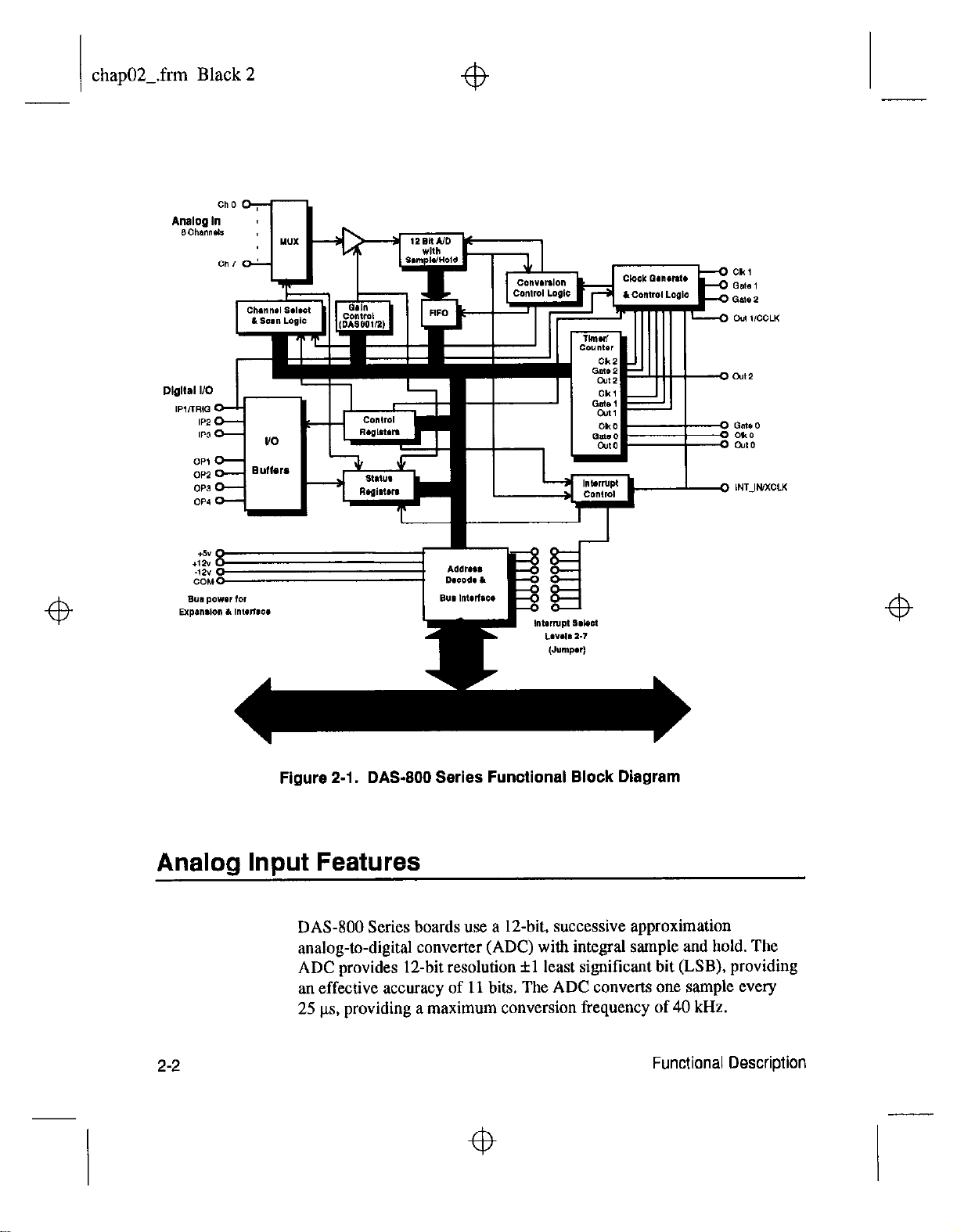
Figure 2-1. DAS-800 Series Functional Block Diagram
Analog Input Features
DAS-800 Series boards use a 12-bit, successive approximation
analog-to-digital converter (ADC) with integral sample and hold. The
ADC provides 1Zbit resolution fl least significant bit (LSB), providing
an effective accuracy of 11 bits. The ADC converts one sample every
25 ks, providing a maximum conversion frequency of 40 kHz.
2-2
4
Functional Description
4
chap02-.frm Black 3
Channel Configuration
DAS-800 Series boards contain eight on-board analog input channels.
The following subsections describe the input configurations supported for
each channel, the gains
the methods of specifying a channel or channels for an analog input
operation.
On the DA%801 and DAS-802, you can configure each channel as either
single-ended or differential. The differences between a single-ended and a
differential input configuration are described as follows:
and
input ranges supported for each channel, and
4
. Single-ended
you are measuring relatively high-level signals (greater than 1 V), if
the source of the input signal is close to the board (less than two feet),
or if all input signals are referred to a common ground. This
configuration does not provide common-mode noise rejection.
. Differential
are measuring low-level signals, if high source resistances (greater
than 100 D) exist, or if common-mode voltages exist between the
voltage source and the host’s chassis ground. In a differential
configuration, a separate positive and negative terminal is provided
for each channel. Any common-mode noise that is picked up equally
on both inputs is rejected because the difference is zero.
You specify the input configuration by setting switches on the board. The
switches connect or disconnect the inverting side of the input signal to
low-level ground. Refer to page 3-16 for information on setting the
switches.
Notes: On the DAS-800, the
single-ended; ah signals are referred to a single low-level ground.
- A single-ended input configuration is appropriate if
- A differential input configuration is appropriate if you
channels are always configured as
4
If you are using BXP-16, EXP-16/A, or EXP-GP expansion
MB-02 backplanes, you must configure the on-board analog input
channels associated with the expansion boards or backplanes as
single-ended.
boards or
4
2-3
chap02Lfrm Black 4
Gains and Ranges
4
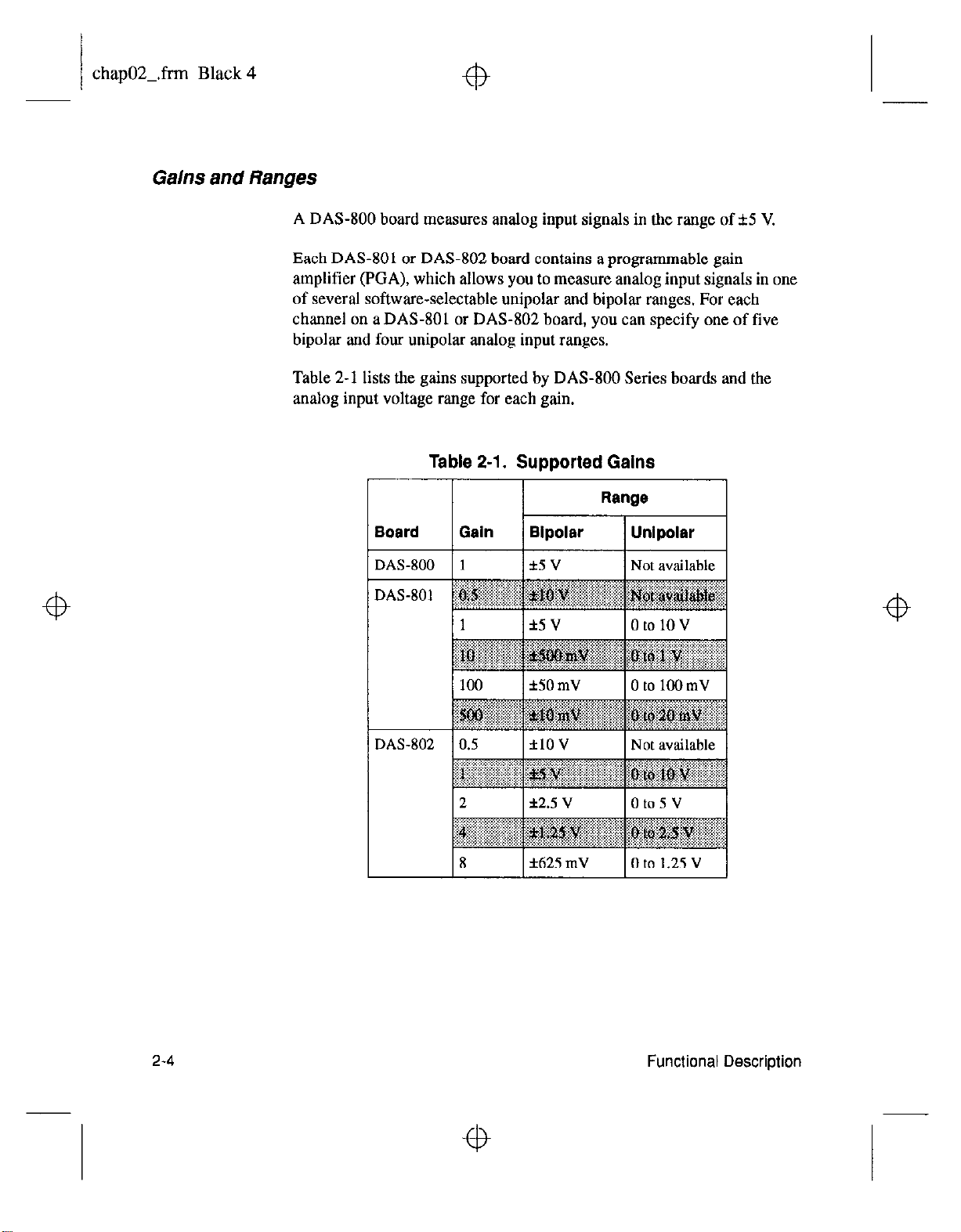
A DAS-800 board measures analog input signals in the range of f5 V.
Each DAS-801 or DAS-802 board contains a programmable gain
amplifier (EGA), which allows you to measure analog input signals in one
of several software-selectable unipolar and bipolar ranges. For each
channel on a DAS-801 or DAS-802 board, you can specify one of five
bipolar and four unipolar analog input ranges.
Table 2-1 lists the gains supported by DAS-800 Series boards and the
analog input voltage range for each gain.
Table 2-l. Supported Gains
2-4
4
Functional Description
4

chap02-.frm Black 5
4
4
Note:
with protection against signals outside the specified analog input range.
All DAS-800 Series boards can tolerate voltages up to f35 V and
transients of several hundred volts without damaging the board.
When measuring signals at differential inputs, DAS-801 and DAS-802
boards can tolerate common-mode voltages up to f35 V and transients of
several hundred volts without damaging the board; however, for normal
operation of the board, make sure that the common-mode voltage is no
more than 12 V - ((C / 2) x
differential input voltage.
Channel Selection
You can use DAS-800 Series boards to acquire data from a single analog
input channel or from a range of contiguous, on-board analog input
channels using automatic channel scanning. These two methods of
channel selection are described as follows:
.
Analog input channels on DAS-800 Series boards are provided
V,),
Single
initiate a conversion.
channel - You use software to specify a single channel and
where G is tbe gain and
V,
is the
4
. Automatic channel scanning
and last channels in a range of contiguous, on-board channels (0 to 7).
The channels are sampled in order from first to last; the hardware
automatically increments the analog input multiplexer address shortly
after the start of each conversion. When the last address is reached,
the multiplexer returns to the start address and the channels are
sampled again. For example, assume that the start channel is 4, the
stop channel is 7, and you want to acquire five samples. Your
program reads data first from channel 4, then from channels 5, 6, and
7, and finally from channel 4 again.
The start channel can be higher than the stop channel. For example,
assume that the start channel is 7, the stop channel is 2, and you want
to acquire five samples. Your program reads data first from channel 7,
then from channels 0, 1, and 2, and finally from channel 7 again.
When using automatic channel scanning, all contiguous, on-board
channels must have the same gain (analog input range).
- You use software to specify the first
2-5
4

chap02Lfrm Black 6
fb
Note:
that includes channels on expansion boards or MB Series backplanes,
you can create a group of consecutive channels through software. tn
addition, if your application requires non-consecutive channels or
different gains for each channel, you can create a channel-gain list
through software. The DAS-800 Series Function Call Driver provides
functions for creating a group of consecutive channels or
channel-gain list; refer to the
User’s
you to set up a group of consecutive channels or channel-gain list;
refer to Chapter 5 for more information. You can also set up a group
of consecutive channels or channel-gain list using DAS-800 Series
custom controls; refer to
Guide
Automatic channel scanning is a hardware feature. The functions
used to create a group of consecutive channels or a channel-gain list
emulate automatic channel scanning through software. Therefore, the
maximum attainable conversion frequency is reduced when using a
group of consecutive channels or a channel-gain list.
Channel Expansion
If you want to acquire
Guide
for more information. The Control Panel also allows
the VisualDAS Custom Controls User’s
for more information.
data
from a range of multiple channels
DAM00 Series Function Call Driver
Z-6
If you require additional analog input channels or signal conditioning for
transducer inputs, you can use any combination of up to eight 16-channel
EXP-16 expansion boards, eight 16-channel EXP-16/A expansion boards,
and/or eight X-channel EXP-GP expansion boards to increase the number
of available channels to 128. You can also use up to four MB-02
backplanes to increase the number of available channels to 68.
For the EXP-16, EXP-16/A. and EXP-GP, you attach the expansion
boards in a daisy-chain configuration using the S-1800 or C-1800 cable.
The first expansion board in the daisy chain is associated with on-board
channel 0, the next expansion board is associated with
1, and so on. You specify the associated on-board channel by setting a
jumper on each expansion board. You can access any unused on-board
channels by attaching an STA-08 or STA-OBPGA screw terminal
accessory to the last expansion board in the daisy-chain configuration.
on-board
Functional Description
channel
chapOZ.frm Black 7
fb
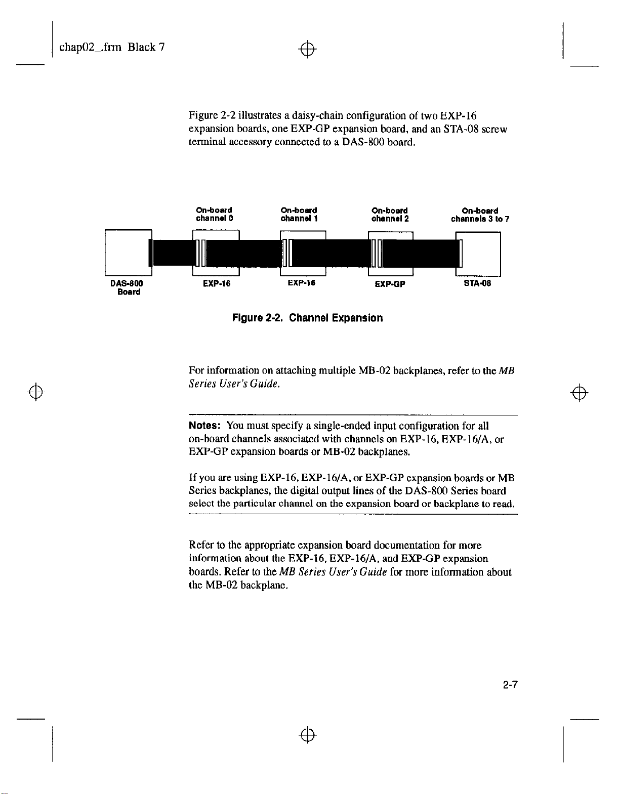
Figure 2-2 illustrates a daisy-chain configuration of two EXP-16
expansion boards, one EXP-GP expansion board, and an STA-08 screw
terminal accessory connected to a DAS-800 board.
Omboard
channel 0
I I I I r I I I
D&3-600
Board
EXP.16
Figure 2-2. Channel Expansion
On-board On-board
channel 1
EXP-16
channal2 chsnnsls 3 to 7
EXPQP
For information on attaching multiple MB-02 backplanes, refer to the ME
Series User’s Guide.
Notes:
You must specify a single-ended input configuration for all
on-board channels associated with channels on EXP-16, EXP-16/A. or
EXP-GP expansion boards or MB-02 backplanes.
If you are using EXP-16, EXP- 16/A, or EXP-GP expansion boards or MB
Series backplanes, the digital output lines of the DAS-800 Series board
select the particular channel on the expansion board or backplane to read.
On-board
STA.08
Refer to the appropriate expansion board documentation for more
information about the EXP-16, EXP-16/A, and EXP-GP expansion
boards. Refer
to the ME Series User’s Guide
for more information about
the MB-02 backplane.
2-7
chap02-.frm Black 8
Conversion Clock Sources
4
The conversion clock source determines when each analog-to-digital
(A/D) conversion is initiated. DAS-800 Series boards provide the
following software-selectable conversion clock sources:
. Software -When using a software conversion clock, the host
computer issues a command to initiate a conversion. The host polls
the board to determine if the conversion is complete. When the
conversion is complete, the host reads the data from the ADC and
returns the value. If the host reads data before the conversion is
complete, the data will be invalid.
Software-initiated conversions are suitable for measuring DC
voltages; however, in applications where you must accurately control
the sampling rate (as when measuring time-varying signals), it is
recommended that you use either an internal or an external hardware
conversion clock source.
4
At power-up or system reset, the board assumes that conversions will
be initiated through software.
. Hardware (internal clock source) -The internal clock source uses
the on-board 8254 counter/timer circuitry and a crystal-controlled
I MHz time base. The 8254 counter/timer circuitry is normally in an
idle state. When you start an analog input operation, a conversion is
initiated immediately. The 8254 is loaded with its initial count value
and begins counting down. When the 8254 counts down to 0, another
conversion is initiated and the process repeats.
Because the 8254 counter/timer uses a 1 MHz time base, each count
represents 1 ps. For example, if you load a count of 25, the time
interval between conversions is 25 ps: if you load a count of 65536,
the time interval between conversions is 65.536 ms.
4
2-6
Functional Description
4

chap02Lfrm Black 9
+b
The 8254 contains three counter/timers: C/TO, Cnl, and C/r2. If you
are using a hardware internal clock source, the time base logic uses
C/T1 and C/r2 in either normal or cascaded mode, as follows:
- Normal
of the 8254 counter/timer circuitry. Each time C/r2 reaches
terminal count, a conversion is initiated. The time interval
between conversions ranges from 25 FLS to 65.536 ms.
Cascaded Mode
C/r2 and C/r1 of the 8254 counter/timer circuitry. When CK2
counts down to 0, CR1 decrements by 1. Cn2 is reloaded with
its count value and begins counting down again. Each time C/r2
counts down to 0, Cm1 decrements by 1. Each time both C/r2
and CR1 reach terminal count, a conversion is initiated. The time
interval between conversions ranges from 25 ps to 1.2 hours.
Note:
system reset, the DA%800 board connects the clock input of C/r2 to
the CPU bus clock divided by two. If you specify a hardware internal
clock source through software, the DAS-800 board connects the clock
inputs of C/T1 and CD2 to the 1 MHz time base. The DAS-801 and
DAS-802 boards always connect the clock input of C/f2 to the
1 MHz time base.
Refer to page 2-17 for more information about the 8254 counter/timer
circuitry.
Mode
- A software-selectable count is loaded into C/r2
- A software-selectable count is divided between
For compatibility with the DAS-8 board, on power-up or
. Hardware (external clock source) - An external clock source is
useful if you want to sample at rates not available with the 8254
counter/timer circuitry, if you want to sample at uneven intervals, or if
you want to sample on the basis of an external event. An external
clock also allows you to synchronize conversions on multiple boards
to a common timing source.
2-9

chap02-.frm Black 10
fb
The external clock source is an externally applied TTL-compatible
signal, which you attach to the INT-IN / XCLK pin (pin 24) of the
main I/O connector. When you start an analog input operation,
conversions are
soume (and at every subsequent falling edge of the external clock
source), a conversion is initiated.
armed.
At the next falling edge of the external clock
Note:
use the INT-IN / XCLK pin (pin 24) to generate interrupts.
Figure 2-3 illustrates how conversions are initiated when using an internal
and an external clock source. (Note that Figure 2-3 assumes that you are
not using a hardware trigger; refer to Figure 2-4 for an illustration of
conversions when using a hardware trigger.)
If you are using a hardware external clock source, you cannot
2-l 0
Figure 2-3. Initiating Conversions
Functional Description
chap02Lfrm Black 11
Notes: The ADC acquires data at a maximum of 40 kHz (one sample
every 25 ns). If you are using a hardware external clock, make sure that
the clock does not initiate conversions at a faster rate than the ADC can
handle.
To achieve full measurement accuracy when using a gain of 500, you
should limit me conversion frequency to a maximum of 25 kHz (one
sample every 40 its).
If you are acquiring samples from multiple channels. the maximum
sampling rate for each channel is equal to 40 kHz divided by the number
of channels.
The rate at which the computer can reliably read data from the board
depends on a number of factors, including your computer, the operating
system/environment, whether you are using expansion boards, the gains
of the channels, and software issues.
You can synchronize conversions on multiple DAS-800 Series boards to a
common, externally applied conversion clock. In addition, you can use a
DAS-801 or DAS-802 board as a timing master; the output of the OUT1
pin (pin 5) on the main I/O connector of the master board acts as an
external hardware conversion clock to any additional boards. You can use
external circuitry, such as CEO on the 8254, to divide the rate of the
master clock; this allows you to synchronize conversions on the
additional hoards to a rate different from that of the master board. Refer to
page 4-13 for more information on synchronizing conversions on multiple
boards.
2-11
chap02_.frm Black 12
Triggers
A trigger is an event that must occur before a DAS-800 Series board starts
an analog input operation. You can use one of the following trigger
sources to trigger aa analog input operation:
. Software - When you start the analog input operation, conversions
begin
immediately.
. Hardware - You connect a digital trigger signal to the digital input
IP 1 /TRIG pin (pin 25) of the main I/O connector. The trigger event
occurs when the board detects a rising edge on IP1 /TRIG.
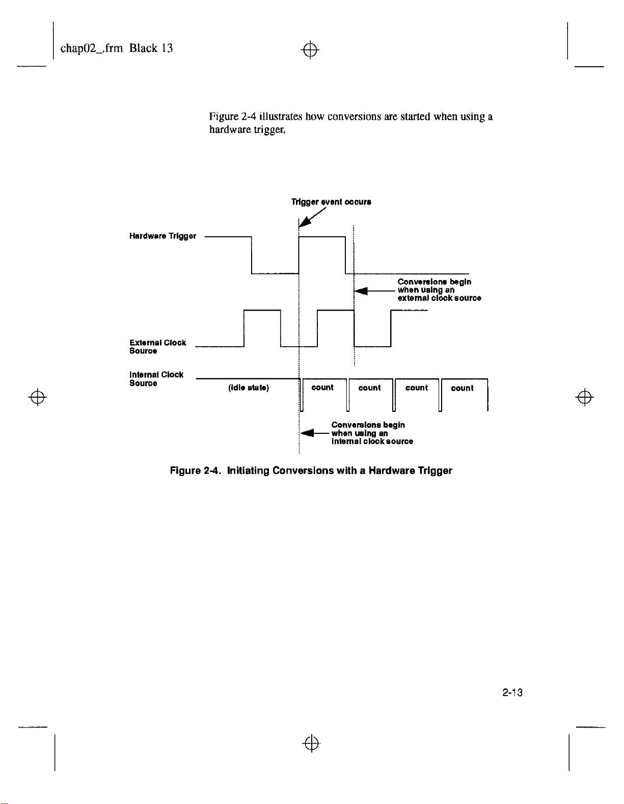
The actual point at which conversions begin depends on whether you
are using an internal or external clock soorce. These considerations
are described as follows:
-
Internal clock
source - The 8254 counter/timer circuitry remains
idle until the trigger event occurs. When the trigger event occurs,
the
board
initiates the first conversion immediately.
- Enrernal
clock
source - Conversions are armed when the trigger
event occurs. At the next falling edge of the external clock
source, the board initiates the first conversion.
2-12
Functional Description
chap02-.frm Black 13
Figure 2-4 illustrates how conversions are started when using a
hardware trigger.
External Clock
source
Figure 24. Initiating Conversions
!
!
with
a Hardware Trigger
2-13
chap02-.frm Black 14
Hardware Gates
A hardware gate is an externally applied digital signal that determines
whether conversions occur. You connect the gate signal to the IPl /TRIG
pin (pin 25) on the main I/O connector. DAS-800 Series boards support a
positive gate only. Therefore, if the hardware gate is enabled and the
signal to IPl /TRIG is high, conversions occur; if the signal to IPl /
TRIG is low. conversions are inhibited.
Note:
You cannot use the hardware gate with a hardware trigger.
However, the gate signal itself can act as a trigger. If the gate signal is low
when the software starts the analog input operation, the board waits until
the gate signal goes high before conversions begin.
When using the hardware gate, the way conversions are synchronized
depends on whether you are using a hardware external clock or a
hardware internal clock, as follows:
. External
clock
- The signal from the external clock continues
uninterrupted while the gate signal is low; therefore, conversions are
synchronized to the external clock.
. Internal clock - The 8254 does not count while the gate signal is low.
Whenever the gate signal goes high, the 8254 is loaded with its initial
count value and starts counting; therefore, conversions are
synchronized to the gate signal.
Figure 2-5 illustrates how to use the hardware gate with both an external
clock and an internal clock.
2-14
Functional Description

chap02-.frtn Black 15
sonware starts
ths
operation -b
3rd convmsion
2nd conversion
/ /
p-r . . . . . . * . . . . .
at wnverslon ,
(Intcmsl clock)
Note:
analog trigger, you can program an analog trigger through software, using
one of the analog input channels as the trigger channel. The DAS-800
Series Function Call Driver provides functions for an analog trigger; refer
to
the DAS-800 Series Funciion Call Driver User’s Guide
information. The Control Panel also allows you to set up an analog
trigger; refer to Chapter 5 for more information. You can also set up an
analog trigger using DAS-800 Series custom controls; refer to the
VisualDAS
2nd mnvwston
(Inkmel clock)
Figure 2-5. Hardware Gate
t
3rd l2dverslon
(Internal clock)
4th converslbn
(Internalclock)
A-
Although DAS-800 Series boards do not provide a hardware-based
for more
Custom
Controls Lrser’x Guide
for more information.
2-I 5
 Loading...