

Page 1

cover.frm Black 1
DAS-800 Series
Function Call Driver
User’s Guide
Page 2

1 titlepgfrm Black 1
DAS-800 Series
Function Call Driver
User’s Guide
Revision A - December 1993
Part Number: 66770
Page 3

noticep.frm Black 1
The information contained in this manual is believed to be accurate and reliable. However. the
manufacturer assumes no responsibility for its use; nor for any infringements or patents or other rights
of third parties that may result from its use. No license is granted by implication or otherwise under any
patent rights of the manufacturer.
THE MANUFACTURER SHALL NOT BE LIABLE FOR ANY SPECIAL, INCIDENTAL, OR
CONSEQUENTIAL DAMAGES RELATED TO THE USE OF THIS PRODUCT. THIS PRODUCT
IS NOT DESIGNED WITH COMPONENTS OF A LEVEL OF RELIABILITY THAT IS SUITED
FOR USE IN LIFE SUPPORT OR CRITICAL APPLICATIONS.
All brand and product names are trademarks or registered trademarks of their respective companies.
0 Copyright Keithley Instruments, Inc., 1993.
All rights reserved. Reproduction or adaptation of any part of this documentation beyond that permitted
by Section I I7 of the 1976 United States Copyright Act without permission of the Copyright owner is
unlawful.
+b
Page 4

800fcd.toc Black iii
Table of Contents
Preface
1
Getting Started
Installing the Software.. 1-2
Installing the DAS-800 Series Standard Software Package 1-2
Installing the ASO- Software Package 1-3
DOS Installation.. 1-3
Windows Installation 1-4
Setting Up the Boards . . . . l-5
Getting Help.. . . l-6
2 Avallable Operations
Analog Input Operations
Operation Modes.
Memory Allocation and Management
Input Range Qpe
.......................................
Gains
Channels
....................................
Single Channel,
Multiple Channels Using a Group of Consecutive
Channels
................................
Multiple Channels Using a Channel-Gain List
Conversion Clocks
Buffering Mode.
Triggers
.....................................
Analog Triggers
Digital Triggers
Hardware Gates.
Digital I/O Operations
Counternimer I/O Operations.
System Operations.
Initializing the Driver.
Initializing a Board
Retrieving the Revision Level.
Handling Errors.
..........................
.............................
.............
.............................
............................
....
............................
..............................
............................
............................
..............................
............................
.....................
..............................
.........................
............................
...................
..............................
,.,2-l
2-2
.2-3
2-5
2-5
.2-6
.,.2-x
.2-9
.2-9
.2-13
.2-16
.2-16
.2-17
.2-20
.2-22
,2-24
: :
2-26
2-27
.2-28
.2-29
: : 2-30 2-30
Page 5

8OOfcd.toc Black iv
Programming with the Function Call Driver
3
How the Driver Works ................................ ,3-l
Programming Overview ............................... .3-5
Preliminary Tasks. ................................... .3-6
Operation-Specific Programming Tasks ,3-6
Analog Input Operations. .3-6
Single Mode, .................................. .3-7
Synchronous Mode ............................. .3-7
Interrupt Mode. ................................ .3-9
Digital I/O Operations ............................. .3-12
Language-Specific Programming Information ............ (3-12
Microsoft C/C++. ................................ .3-13
Borland C/C++ .................................. .3-14
Microsoft QuickC for Windows ..................... .3-I5
Microsoft Visual C++ ............................. .3-16
Borland Turbo Pascal ............................. .3-16
Borland Turbo Pascal for Windows .................. .3-17
Specifying the Buffer Address (Pascal) ............... .3-1X
Specifying the Channel-Gain List Starting
Address (Pascal). ............................... .3-19
Microsoft QuickBASIC (Version 4.0) ................ .3-20
Microsoft QuickBasic (Version 4.5). ................. .3-21
Microsoft Professional Basic (Version 7.0) ............ .3-22
Microsoft Visual Basic for DOS
...................... 3-23
Microsoft Visual Basic for Windows .................. 3-24
Specifying the Buffer Address (All BASIC Languages) .. .3-25
iv
Function Reference
4
DASXOO-DevOpen ........
DAS800-GetADGainMode.
DAS800-GetDevHandle . ...
DAS800-Get8254 : ........
DAS800&SetADGainMode .
DAS800-Set8254 .........
K-ADRead. ..............
K-BufListAdd ............
K-BufListReset ...........
K-ClearFrame ............
K-CloseDriver
K-ClrConiRun
............
............
K-DASDevInit ...........
K-DIRead ...............
........
........
........
........
........
........
........
........
........
........
........
........
........
........
.4-6
.4-9
.4-II
.4-13
.4-15
.4-17
.4-19
.4-22
.4-24
,4-26
,4-28
.4-30
4-32
.4-33
Page 6

800fcd.toc Black v
K-DOWrite ..............
K-FormatChanGAry
K-FreeDevHandle
K-FreeFrame
.........
.............
K-GetADFrame. ..........
KGetADTrig ............
K-GetBuf. ...............
K-GetChn ...............
K-GetChnGAry
K-GetClk
................
K-GetClkRate ............
K-GetContRun ...........
K-GetDevHandIe. .........
K-GetDITrig .............
K-GetErrMsg. ............
K-GetG .................
K-GetGate
K-GetStartStopChn
KGetStartStopG
...............
........
..........
K-GetTrig ...............
K-GetTrigHyst. ...........
K-GetVer
................
K-InitFrame. .............
K-IntAlloc
K-IntFree
...............
................
K-IntStart. ...............
K-IntStatus ..............
KJntStop. ...............
K-MoveBuffoArray .......
K-OpenDriver
K-RestoreChanGAry
............
.......
K-SetADTrig. ............
K_SetBuf ................
K-SetBufI ...............
K-SetChn. ...............
K-SetChnGAry ...........
K-SetClk ................
K-SetClkRate ............
K-SetContRun. ...........
K-SetDITrig. .............
K-SetG. .................
K-SetGate ...............
.4-35
.4-37
.4-3x
.4-39
.4-40
.4-42
.4-44
,446
. ..4-48
.4-50
.4-52
.4-54
.4-56
. ..4-58
.4-60
.4-61
.4-63
.4-65
,4-67
.4-70
.4-72
,4-14
.4-76
.4-7x
,4-80
.4-81
.4-x3
.4-X6
4-88
.4-x9
.4-92
.4-93
.4-95
.4-97
.4-99
,4-101
.4-103
.4-I05
.4-107
.4-109
..4-111
.4-113
Page 7

SOOfcd.toc Black vi
K-SetStartStopChn ............................
K-SetStartStopG ..............................
K-SetTrig .................................... .4-120
K-SetTrigHyst
................................ 4-122
K-SyncStart ..................................
A Error/Status Codes
B
Data Formats
Converting Raw Counts to Voltage
Converting Voltage to Raw Counts
Specifying an Analog Trigger Level.
Specifying a Hysteresis Value.
Index
List of Figures
Figure 2-l.
Analog Input Channels
Figure 2-2. Channel-Gain List (C or Pascal)
Figure 2-3. Sample Channel-Gain List (C or Pascal).
Figure 2-4. Channel-Gain List (BASIC)
Figure 2-5. Sample Channel-Gain List (BASIC).
Figure 2-6. Initiating Conversions
Figure 2-7. Analog Trigger Conditions
Figure 2-8. Using a Hysteresis Value. . .
Figure 2-Y. Initiating Conversions with an External
Analog Trigger
Figure 2-10. Initiating Conversions with an External
Digital Trigger. . 2-21
Figure 2-l I. Hardware Gate. : : 2-23
Figure 2-12. Digital Input Bits. .2-24
Figure 2-13. Digital Output Bits. .2-25
.4-115
.4-l I7
4-124
B-2
.B-3
.B-3
.B-5
.2-x
.2-IO
.2-I1
.2-I2
.2-12
.2-I5
.2-I7
2-19
.2-20
vi
Page 8

SOOfcd.toc Black vii
List of Tables
Table 2-l.
Supported Operations .2-l
Table 2-2. Analog Input Ranges., .2-6
Table 2-3.
Table 3-l.
Table 3-2.
Channels in Maximum Configuration. .2-7
A/D Frame Elements. .3-3
Setup Functions for Synchronous-Mode
Operations.. . . . . . . . . . . . .3-7
Table 3-3.
Table 4-1.
Table 4-2.
Setup Functions for Interrupt-Mode Operations .3-IO
FCD Functions. . .4-2
Default Configuration .4-7
Table A- I. Error/Status Codes. A-l
vii
Page 9

800fcd.toc Black viii
Page 10

preface.frm Black ix
+b
Preface
The
DAS-BOO Series Function Call Driver User’s Guide
write application programs for DAS-800 Series boards using the
DA.%800 Series Function Call Driver. The DAS-X00 Series Function Call
Driver supports the following DOS-based languages:
. Microsoft@ QuickBASIC (Version 4.0)
l
Microsoft QuickBasicm (Version 4.5 and higher)
describes how to
. Microsoft Professional Basic (Version 7.0 and higher)
. Microsoft Visual BasicTM for DOS (Version 1.0)
. Microsoft C/C++ (Version 4.0 and higher)
. Borland@ C/C++ (Version I.0 and higher)
l
Borland Turbo Pascal@ for DOS (Version 6.0 and higher)
The DAS-800 Series Function Call Driver also supports the following
WindowsTM-based languages:
l
Microsoft Visual Basic for Windows (Version 2.0 and higher)
. Microsoft QuickC@ for Windows (Version 1.0)
l
Microsoft Visual C++TM (Version I .O)
. Borland Turbo Pascal for Windows (Version 1.0 and higher)
Page 11

preface.frm Black x
f@
The manual is intended for application programmers using a DAS-800,
DAS-801, or DAS-802 board in an IBM’ PC/XY, ATa or compatible
computer, It is assumed that users have read the
Guide
to familiarize themselves with the boards’ functions, and that they
DAS-800 Series User’s
have completed the appropriate hardware installation and configuration. It
is also assumed that users are experienced in programming in their
selected language and that they are familiar with data acquisition
principles.
The
DAS-800
Series
Function Call Driver
User’s
Guide
is organized as
follows:
Chapter I contains the information needed to install the DAS-800
Series Function Call Driver and to set up DAS-800 Series boards.
Chapter 2 contains the background information needed to use the
functions included in the DAS-800 Series Function Call Driver.
Chapter 3 contains programming guidelines and language-specific
information related to using the DA.5800 Series Function Call
Driver.
Chapter 4 contains detailed descriptions of the DAS-XtlO Series
Function Call Driver functions, arranged in alphabetical order.
Appendix A contains a list of the error codes returned by DAS-800
Series Function Call Driver functions.
Appendix B contains instructions for converting raw counts to
voltage and for converting voltage to raw counts.
An index completes this manual.
Page 12

prefacefrm Black xi
Keep the following conventions in mind as you use this manual:
. References to DAS-800 Series boards apply to the DAS-800,
DAS-801, and DAS-802 boards. When a feature applies to a
particular board, that board’s name is used.
. References to BASIC apply to all DOS-based BASIC languages
(Microsoft QuickBASIC (Version 4.0). Microsoft QuickBasic
(Version 4.5), Microsoft Professional Basic, and Microsoft Visual
Basic for DOS). When a feature applies to a specific language, the
complete language name is used. References to Visual Basic for
Windows apply to Microsoft Visual Basic for Windows.
. Keyboard keys are enclosed in square brackets ([ 1).
4
xi
4
Page 13

preface.frm Black xii
4
4
Page 14
chapOl_.frm Black 1
fb
Getting Started
The DAS-800 Series Function Call Driver is a library of data acquisition
and control functions (referred to as the Function Call Driver or FCD
functions). It is part of the following two software packages:
4
. DAS-X00
package that is shipped with DAS-800 Series boards; it includes the
following:
-
- Support files, containing such program elements as function
-
-
.
ASOSoftware Option for DAS-800 Series boards. You purchase the
ASO- software package separately from the board; it includes the
following:
Series
Libraries of FCD functions for Microsoft QuickBASIC
(Version 4.0) Microsoft QuickBasic (Version 4.5), Microsoft
Professional Basic, and Microsoft Visual Basic for DOS.
prototypes and definitions of variable types, which are required
by the FCD functions.
Utility programs, running under DOS, that allow you IO
configure, calibrate, and test the functions of DAS-800 Series
boards.
Language-specific example programs,
software package
Libraries of FCD functions for Microsoft C/C++, Borland
C/C++, and Borland Turbo Pascal.
standard
software package -This
- This is the optional Advanced
is the software
4
4
l-l
Page 15

chapOl_.frm Black 2
+D
- Dynamic Link Libraries (DLLs) of FCD functions for Microsoft
Visual Basic for Windows, Microsoft QuickC for Windows,
Microsoft Visual C++. and Borland Turbo Pascal for Windows.
- Support files. containing program elements, such as function
prototypes and definitions of variable types. that are required by
the FCD functions.
- Utility programs, running under DOS and Windows, that allow
you to configure, calibrate, and test the functions of DAS-800
Series boards.
- Language-specific example programs.
This chapter contains the information needed to install the DAS-800
Series Function Call Driver in your computer and set up your DAS-800
Series boards. It also contains information on where to get help if you
have problems installing or using the Function Call Driver.
Installing the Software
Before you can use the Function Call Driver, you must install the
appropriate software package, either the DAS-800 Series standard
software package or the ASO- software package.
The following sections describe how to install the DAS-800 Series
standard software package and how to install the AS0400 software
package from both DOS and Windows.
Installing the DAS-800 Series Standard Software Package
To install the DAS-800 Series standard software package, perform the
following steps:
1. Make a back-up copy of the supplied disks.
2. Insert disk #l into the disk drive.
l-2
Getting Started
Page 16

chapOl_.frm Black 3
3. Assuming that you are using disk drive A, enter the following at the
DOS prompt:
A:install
The installation program prompts you for your installation
preferences, including the name of the directory you want to copy the
software to. It also prompts you to insert additional disks, as
necessary.
4. Continue to insert disks and respond to prompts, as appropriate.
The installation program expands any files that are stored in a
compressed format and copies them into the directory you specified
(DAS800 directory on hard disk C if you do not specify otherwise).
5. Review the following tiles:
- FILES.TXT lists and describes all the files copied to the hard disk
by the installation program.
-
README.TXT contains information that was not available when
this manual was printed.
installing the ASO- Software Package
This section describes how to install the ASO- software package from
both DOS and Windows.
DOS Installation
To install the ASO- software package from DOS, perform the
following steps:
1. Make a back-up copy of the supplied disks.
2. Insert disk #1 into the disk drive.
3. Assuming that you are using disk drive A. enter the following at the
DOS prompt:
A:install
1-3
Page 17

chapOl_.frm Black 4
The installation program prompts you for your installation
preferences, including the name of the directory you want to copy the
software to. It also prompts you to insert additional disks, as
necessary.
4. Continue to insert disks and respond to prompts, as appropriate.
The installation program expands any files that are stored in a
compressed format and copies them into the directory you specified
(AS0800 directory on hard drive C if you do not specify otherwise).
5. Review the following files:
- FILES.TXT lists and describes all the files copied to the hard disk
by the installation program.
-
README.TXT contains information that was not available when
this manual was printed.
Windows Installation
To install the ASO- software package from Windows, perform the
following steps:
I. Make a back-up copy of the ASO-Windows disk
2. Insert the ASO-Windows disk into the disk drive.
3. Start Windows,
4. From the Program Manager menu, choose File and then choose Run.
5. Assuming that you are using disk drive A, type the following at the
command line in the Run dialog box, and then select OK:
The installation program prompts you for your installation
preferences, including the name of the directory you want to copy the
software to.
6. Type the path name and select Continue.
A: SETUP
1-4
Getting Started
Page 18

chapOl_.frm Black 5
Setting Up the Boards
fb
The installation program expands any tiles that are stored in a
compressed format and copies them into the directory you specified
(ASOBOWWINDOWS directory on hard drive C if you do not specify
otherwise).
The installation program also creates a DAS-800 family group; this
group includes example Windows programs and help files.
7. Review the following files:
-
FILES.TXT lists and describes all the tiles copied to the hard disk
by the installation program.
- README.TXT contains information that was not available when
this manual was printed.
Before you use the Function Call Driver. make sure that you have
performed the following steps:
1. Installed the software.
If not, install the appropriate software package (either the DAS-800
Series standard software package or the ASO- software package)
on your IBM PC/XT, AT or compatible computer. Refer to page 1-2
for information on installing the DAS-800 Series standard software
package; refer to page 1-3 for information on installing the ASO-8OU
software package.
2. Created a configuration file.
If not, use the DXOOCFG.EXE utility to create a configuration file for
the DAS-800 Series boards you are using. For each board, make sure
that you specify the board model, the base address, the use of
counter/timer 2 (C/IY2) on the 8254 counter/timer circuitry, the input
range type (unipolar or bipolar), the input configuration (single-ended
or differential) for each channel on each DAS-801 and DAS-802
board, the interrupt level, and the expansion boards used. Refer to the
DAS-800 Series
(/ser’s
Guide
for more information.
l-5
Page 19

chapOl_.frm Black 6
3. Configured the hardware.
If not, use switches on the boards to set the base address of each
DA.%800 Series board and the input contiguration (single-ended or
differential) for each channel on each DAS-801 and DAS-802 board.
Use the jumper on the boards to set the interrupt level of each
DAS-800 Series board. Refer to the instructions in the
DXOOCFG.EXE utility and the
DAS-800 Series User’s Guide
for more
information.
4. Installed the board(s).
If not, with the computer powered down, install the DAS-800 Series
boards in your computer. The DAS-800 requires a single, short slot;
the DAS-801 and DAS-802 require a single, l/2-slot. Refer to the
documentation provided with your computer for more information on
installing boards.
5. Tested the board(s), if desired.
Getting Help
If you need help installing or using the DA.%800 Series Function Call
Driver, contact the factory.
Note: The DAS-800 Series Function Call Driver supports a
maximum of four DAS-800 Series boards.
If you want to test the functions of the boards before writing your
application program, use the CTLXOO.EXE utility (for DOS) or the
CTLXOOW.EXE utility (for Windows). Refer to the
User’s
Guide
for more information.
DA.5800 Series
l-6
-
Page 20

chapOl_.frm Black 7
An applications engineer will help you diagnose and resolve your
problem over the telephone. Please make sure that you have the following
information available before you call:
Software package Version
Invoice/order #
4
Compiler
Operating system
Computer
DAS-800 board
Language
Manufacturer
Version
DOS
version
Windows version 3.0 3.1
mode Standard Enhanced
Manufacturer
CPU type
Clock speed (MHz)
Math coprocessor
Amount of RAM
Video system
BIOS type
Model
Serial I#
Base address setting
Interrupt level setting
Input configuration
Input range type
8254 C/l? usage
8088 286 386 4868 12 20 25 33 _
Yes No
CGA Hercules EGA VGA
800 801 802
2 3 4 5 6 7 None
Single-ended Differential
Unipolar Bipolar
Cascaded Normal
4
Expansion boards ‘I)pe
;;:
;;:
5Pe
4
l-7
Page 21

chapOl_.frm Black 8
Page 22

chap02-.frm Black 1
2
Available Operations
This chapter contains the background information you need to use the
FCD functions to perform operations on DAS-800 Series
supported operations are listed in Table 2- 1.
Table 2-1. Supported Operations
Operation Page Reference
boards.
The
Analog
Counter/timer l/O
input
Analog Input Operations
This section describes the following:
. Analog input operation modes available.
. How to allocate and manage memory.
. How to modify the input range type.
. How to specify channels and gains, a conversion clock source. a
buffering mode, and a trigger source for an analog input operation.
page 2-I
page 2-26
2-l
Page 23

chap02-.frm Black 2
Operation Modes
The operation mode determines which attributes you can specify for an
analog input operation and whether the operation is performed in the
foreground or in the background. You can perform analog input
operations in one of the following modes:
. Single
mode
- In single mode, the board acquires a single sample
from an analog input channel. The driver initiates the conversion and
the board acquires the data in the foreground: you cannot perform any
other operation until the single-mode operation is complete.
You use the K-ADHead function to start an analog input operation in
single mode. You specify the board you want to use, the analog input
channel, the gain at which you want to read the signal, and the
variable in which to store the converted data.
. Synchronous mode - In synchronous
mode, the board acquires a
single sample or multiple samples from one or more analog input
channels. A hardware conversion clock initiates conversions while
the board acquires data in the foreground: you cannot perform any
other operation until the synchronous-mode operation is complete.
After the driver transfers the specified number of samples to the host.
it returns control to the application program, which reads the data.
Synchronous mode provides the fastest acquisition of multiple
samples.
You use the K-SyncStart
function to start an analog input operation
in synchronous mode. You specify the channel(s). gain(s). conversion
clock source, buffer address, and trigger source.
2-2
. Interrupt mode
- In interrupt mode, the board acquires a single
sample or multiple samples from one or more analog input channels.
A hardware conversion clock initiates conversions while the board
acquires data in the background; system resources can be used by
other programs. The driver transfers data to the host in the
background using an interrupt service routine.
You use
the
K-In&art
function to start an analog input operation in
interrupt mode. You specify the channel(s), gain(s), conversion clock
source, buffering mode, buffer address, and trigger source.
Available Operations
Page 24

chap02-.frm Black 3
+b
You can specify either single-cycle or continuous buffering mode for
interrupt-mode operations. Refer to page 2-16 for more information
on buffering modes.
continuous-mode interrupt operation.
You
can
use the K-IntStatus
of an interrupt operation. In addition,
function to determine the status of all interrupt operations on a
particular board.
For single mode, synchronous mode, and interrupt mode, the converted
data is stored as raw counts. For information on converting raw counts to
voltage, refer to Appendix B.
Note: In applications where you must accurately control the sampling
rate, it is recommended that you perform the analog input operation in
either synchronous mode or interrupt mode so that you can specify a
conversion clock source.
You
can
use the K-IntStop
function to determine the current status
you can use the K-InitFrame
function 10 stop a
Memory Allocation and Management
Synchronous-mode and interrupt-mode analog input operations require a
memory buffer in which to store the acquired data. You can provide the
required memory buffer in one of the following ways:
. Within your application program’s memory area
memory buffer is always available to your program; however. your
application program may require a large amount of memory. You can
dimension a local memory buffer for any supported language. Since
the DAS-800 Series Function Call Driver stores data in l6-bit
integers, you must dimension all local memory buffers as integers.
. Outside of your application program’s memory area - You
allocate memory as needed. For all C languages, all Pascal languages,
and Visual Basic for Windows,
to allocate memory dynamically, outside of your program’s memory
area. You specify the operation requiring the buffer, the number of
samples to store in the buffer, the starting address of the buffer, and
the name you want to use to identify the buffer (this name is called the
memory handle). When the buffer is no longer required. you can free
- The local
you can use the K-IntAlloc
function
2-3
Page 25

chap02Lfrm Black 4
the buffer for another use by specifying this memory handle in the
K-IntFree
function.
Note:
You cannot allocate memory dynamically in BASIC; in
BASIC, you must dimension the memory buffer locally.
You can use multiple buffers to increase the number of samples you can
acquire. Each synchronous-mode or interrupt-mode analog input
operation has a buffer list associated with it. You can use the
K-BufListAdd
You can use the K-BufListReset
function to add a buffer to the list of multiple buffers.
function to clear the list of multiple
buffers.
Note:
If you are using a Windows-based language in Enhanced mode,
you may be limited in the amount of memory you can allocate. If you are
allocating memory dynamically or if you are using multiple buffers. it is
recommended that you use the Keithley Memory Manager before you
begin programming to ensure that you can allocate a large enough buffer
or buffers. Refer to the
DAS-800 Series User’s Guide
for more
information about the Keithley Memory Manager.
After you allocate or dimension your buffer(s). you must specify the
starting address of the buffer(s) and the number of samples to store in the
buffer(s), as follows:
2-4
l
For BASIC
- You use the
K SetBufI
function to specify the starting
address of a single, locally dimensioned memory buffer. When using
multiple buffers, you
use the K-BufListAdd
function both IO add
buffers to the multiple-buffer list and to specify the starting address of
each buffer.
. For Visual Basic for Windows - You use the K SetBufl
function to
specify the starting address of a single, locally dimensioned integer
memory buffer; you use the
address of a single buffer allocated dynamically using
When using multiple buffers, you use the
K-SetBuf function
K-BufListAdd
to specify the starting
K-IntAlloc.
function
both to add buffers to the multiple-buffer list and to specify the
starting address of each buffer.
Available Operations
Page 26

chap02-.frm Black 5
Input Range Type
Note: If you allocated your buffer dynamically using K~lntAlloc,
you
must use the
K-MoveBufIbArray
function to transfer the
acquired data from the dynamically allocated buffer to a local buffer
that your Visual Basic for Windows program can we. Refer to page
3-25 for more information.
l
For C and Pascal - You use the K-SetBuf function to specify the
starting address of a single buffer, whether the buffer was
dimensioned locally or allocated dynamically using
When using multiple buffers, you use the
K-BuIListAdd
K-IntAlloc.
function
both to add buffers to the multiple-buffer list and to specify the
starting address of each buffer.
Normally, the driver determines the input range type for a DAS-801 or
DAS-802 board (bipolar or unipolar) by reading the configuration tile.
You can change the input range type without modifying the configuration
file by using the
DAS800-SetADGainMode function.
Gains
Note: The input range type of the DAS-800 board is always bipolar.
Use the
range type. If
DAS800 GetADGainMode
contigu&on file; if you have used
DAS800-GetADGainMode
DAS800-GetADGainMode
you never used DASSOO SetADGainMode,
function to get the current input
reads the%put range type from the
DASSOO-SetADGainMode.
reads the last input range type you
programmed through software.
DAS-800 boards measure analog input signals in the range of f5 V.
DA%801 and DAS-802 boards measure analog input signals in one of
several software-selectable unipolat and bipolar ranges. For each channel
on aDAS- or DAS-802 board, you can select one of five bipolar and
four unipolar analog input ranges.
Z-5
Page 27

chap02-.frm Black 6
Table 2-2 lists the analog input ranges supported by DAS-800 Series
boards and the gain and gain code associated with each range. (The gain
code is used by the FCD functions to represent the gain.)
Table 2-2. Analog Input Ranges
4
Channels
Board
I DAS-800 1 fS V
The analog input channels are the analog input connections from which
you acquire data. DAS-800 Series boards contain eight on-board analog
input channels, numbered 0 through 7. If you require additional channels,
you can use any combination of up to eight I&channel EXP-16 or
EXP-16/A expansion boards and/or 8-channel EXP-GP expansion boards
to increase the number of available channels to 128. You can also use up
to four MB-02 backplanes to increase the number of available channels to
68.
isi Gal”
1 Not available
1
Gain Code
lo I
2-6
4
Available
Operations
Page 28

chap02-.fnn Black 7
Expansion boards are assigned to consecutive on-board analog input
channels, beginning with on-board channel 0. To ensure that the DA.%X00
Series Function Call Driver reads the channel numbers correctly. you
must attach all EXP- I6 and EXP-16/A expansion boards first, followed
by all EXP-GP expansion boards. You can also use the remaining
on-board channels. Refer to the
appropriate expansion board documentation for more information.
The maximum supported configuration is eight EXP-16 or EXP- 16/A
expansion boards, eight EXP-GP expansion boards, or four MB-02
backplanes. Table 2-3 lis!s the software channels associated with each
expansion board.
Table 2-3. Channels In Maximum Configuration
DAS-800 Series User’s Guide
Software Channels
or the
4
4
Figure 2- 1 illustrates the use of one EXP- 16 expansion board, two
EXP-GP expansion boards, and the five remaining on-board channels.
The channels on the EXP-16 attached to analog input channel 0 are
referred to in software as channels 0 to 15; the channels on the EXP-GP
attached to analog input channel 1 are referred to in software as channels
16 to 23; the channels on the EXP-GP attached to analog input channel 2
are referred to in software as channels 24 to 3 1; the remaining five
2-7
Page 29

chap02-.frm Black 8
on-board analog input channels (3,4,5.6. and 7) are referred to in
software as channels 32,33,34, 35, and 36.
EXP-16
channels
0.16
rl
I
I
Single Channel
o-
DA8400
sorts. Board
Figure 2-1. Analog input Channels
l-
:
:
;
You can perform an analog input operation on a single channel or on
multiple channels. The following subsections describe how to specify the
channel(s) you are using.
You can acquire a single sample or multiple samples from a single analog
input channel.
For single-mode analog input operations, you can acquire a single sample
from a single analog input channel. You
use the K-ADRead
function to
specify the channel and the gain code.
2-8
For synchronous-mode and interrupt-mode analog input operations. you
can acquire a single sample or multiple samples from a single analog
input channel. You
the
K-SetG
use the K SetChn
function to specify the channel and
function to specify the gain code.
Available Operations
Page 30

chap02-.frm Black 9
Multiple Channels Using a Group of Consecotlve Channels
For synchronous-mode and intemrpt-mode analog input operations, you
can acquire samples from a group of consecutive channels. You use the
K-SetStartStopChn
group. The channels are sampled in order from first to last; the channels
are then sampled again until the required number of samples are read.
For example, assume that you have an EXP-16/A expansion board
attached to on-board channel 0. You specify the start channel as 14, the
stop channel as 17. and you want to acquire five samples. Your program
reads data first from channels 14 and 15 (on the EXP-16/A), then from
channels 16 and 17 (on-board channels 1 and 2). and fmally from channel
14 again.
If you are not using any expansion boards, you can specify a start channel
that is higher than the stop channel. For example, assume that the start
channel is 7, the stop channel is 2. and you want to acquire five samples.
Your program reads data first from channel 7. then from channels 0. 1,
and 2. and finally from channel 7 again.
function to specify the first and last channels in the
You can use the K-SetC function to specify the gain code for ah channels
in the group. (All channels in a group of consecutive channels must use
the same gain code.) You can
specify the gain code, the start channel, and the stop channel in a single
function call.
Refer to Table 2-2 on page 2-6 for a list of the analog input ranges
supported by DAM00 Series boards and the gain code associated with
each range.
also
use the K-SetStartStopG function to
Multiple Channels Using a Channel-Gain List
For synchronous-mode and interrupt-mode analog input operations. you
can acquire samples from channels in a channel-gain list. In the
channel-gain list, you specify the channels you want to sample, the order
in which you want to sample them, and the gain code for each channel.
2-9
Page 31

chap02-.frm Black 10
The channels in a channel-gain list are not necessarily in consecutive
order, and you can specify the same channel more than once (up to a total
of 256 channels in the list). For the DAS-801 and DAS-802 boards, you
can use a different gain code for each channel in a channel-gain list; for
the DAS-800 board, every channel must use a gain code of 0 (gain of I).
The channels are sampled in order from the first channel in the list to the
last channel in the list; the channels in the list are then sampled again until
the required number of samples are read.
Refer to Table 2-2 on page 2-6 for a list of the analog input ranges
supported by DAS-X00 Series boards and the gain code associated with
each range.
Note:
The maximum attainable conversion frequency when using a
channel-gain list is less than the maximum attainable conversion
frequency when using a group of consecutive channels.
You specify the channels and gains in one of the following ways:
. For C and Pascal
- You use two adjacent g-bit bytes to specify a
channel and its gain code (the channel number is specilied in the first
byte; the gain code is specified in the second byte). The first two
bytes in the channel-gain list specify the number of channels
(subsequent pairs of bytes) in the list. Figure 2-2 illustrates the format
of a channel-gain list for C or Pascal, where n is the number of
channels (pairs) in the list.
syte 0 1
Value "
#Of pairs
2 3 4
than jeahl than /g&l
pair 1
pair 2
6 ~..~.~. 2n
..- cbn ~ @"
2" + 1
pair n
Z-10
Figure 2-2. Channel-Gain List (C or Pascal)
Available Operations
Page 32

chap02-.frm Black 11
Figure 2-3 illustrates a channel-gain list of four channels on a
DAS-801 board: channel 5 is sampled at a gain of 0.5 (gain code = 1).
channel 2 is sampled at a gain of 10 (gain code = 2) channel 4 is
sampled at a gain of 100 (gain code = 3), and channel 2 is sampled at
a gain of 500 (gain code = 4).
"a,"e 0 4 6 1 2 2 4 3 2 4
Figure 2-3. Sample Channel-Galn List (C or Pascal)
After you create the channel-gain list in C or Pascal, use the
K-SetChnCAry function to specify the starting address of the list.
For Pascal only, you must define a record type for the channel-gain
list before you specify the starting address. Refer to page 3- I9 for
more information.
. For BASIC
and
Visual
Basic for Windows
- You use two adjacent
l6-bit words to specify a channel and its gain code (the channel
number is specified in the first word; the gain code is specified in the
second word). The first word in the channel-gain list specifies the
number of channels (subsequent pairs of words) in the list. Figure 2-4
illustrates the format of a channel-gain list for BASIC and Visual
Basic for Windows, where n is the number of channels (pairs) in the
list.
Z-11
Page 33

chap02-.frm Black 12
Word
V&NJ
0 1
n
cflan
2
b-in
w Of pairs pair 1
Figure 24. Channel-Gain List (BASIC)
Figure 2-5 illustrates a channel-gain list of three channels on a
DAS-80 1 board: channel 5 is sampled at a gain of 0.5 (gain code = 1).
channel 2 is sampled at a gain of 10 (gain code = 2), and channel 4 is
sampled at a gain of 100 (gain code = 3).
Word
I IO 11121314151~1
ValUe 3 5 1 2 2
3
p&s pdr
1 pal, 2
2n.1
Ohm
pair n
4 3
pair 3
2n
win
2-12
Figure 2-5. Sample Channel-Gain List (BASIC)
After you create your channel-gain list in BASIC or Vwal Basic for
Windows,
you
must
use the K FormatChanCAry
function to
convert the 16-bit values to X-bit values that the DAS-800 Series
Function Call Driver can use. After
convert your
list,
use the K-SetChnCAry
you use K-FormatChanCAry
function to specify the
starting address of the list.
Your program cannot read
K-FormatChanCAry
K RestoreChanCAry
the
channel-gain list
converted
by the
function; you must use the
function 10 restore the converted list to its
original format.
Available Operations
to
Page 34

chap02-.frm Black 13
Conversion Clocks
The conversion clock determines the time interval between conversions.
For synchronous-mode and interrupt-mode analog input operations, you
can use the K-SetClk function to specify an internal or an external
conversion clock source. These conversion clock sources are described as
follows:
. Internal clock source
- The internal clock source is tbc on-board
8254 counter/timer circuitry. The 8254 counter/timer circuitry is
normally in an idle state. When you start the analog input operation
(using
K-In&art or K-SyncStart),
a conversion is initiated
immediately. The 8254 is loaded with a count value and begins
counting down. When the 8254 counts down to 0, another conversion
is initiated and the process repeats.
Because the 8254 counter/timer uses a I MHz time base, each count
represents I
KS.
Use the
K-SetClkRate
to specify the number of
counts (clock ticks) between conversions. For example, if you specify
a count of 25, the time interval between conversions is 25 ps; if you
specify a count of 65535, the time interval between conversions is
65.535 ms.
The 8254 contains three counter/timers: CEO, CR I, and C/IT. If you
are using an internal clock source. the 8254 uses both CM and CK I.
The driver uses C/T2 and CKl in either normal or cascaded mode, as
follows:
-
Normal
mode
- The driver loads the count you specify into Cn2
of the 8254 counter/timer circuitry. Each time C/f2 reaches
terminal count, a conversion is initiated. The time interval
between conversions ranges from 25 bs to 65.535 ms.
-
Cascaded mode
- The driver divides the count you specify
between Cn2 and Clrl of the 8254 counter/timer circuiuy.
When C/r2 counts down to 0, CR1 decrements by I. Cfl2 is
reloaded with its count value and begins counting down again.
Each time C/T2 counts down to 0. Cfll decrements by I. Each
time both C/l’2 and C/l’1 reach terminal count. a conversion is
initiated, The time interval between conversions ranges from
25
us to 1.2 hours.
2-l 3
Page 35

chap02-.frm Black I4
Note: You configure the 8254 counter/timer circuitry for normal
mode or cascaded mode using the DBOOCFG.EXE configuration
utility. Refer to the
DAS-800 Series User’s Guide
for more
information.
When using an internal clock source, use the following formula to
determine the number of counts to specify:
counts =
conversion frequency
I MHz
For example, if you want a conversion frequency of 10 kHz. specify a
count of 100.
. External clock source - Use an external clock sonrce if you want to
sample at rates not available with the 8254 counter/timer circuitry. if
you want to sample at uneven intervals. or if you want to sample on
the basis of an external event.
You attach an external clock sonrce to the INT-IN / XCLK pin
(pin 24). When you start the analog input operation (using
K-IntStart
or
K-Sync&art),
conversions are armed. At the next
falling edge of the external clock source (and at every subsequent
falling edge of the external clock source), a conversion is initiated.
Figure 2-6 illustrates the initiation of conversions when using an internal
and an external clock source. (Note that Figure 2-6 assumes that you are
not using an external trigger; refer to Figure 2-10 on page 2-21 for an
illustration of conversions when using an external trigger.)
2-14
Available Operations
Page 36

chap02-.frm Black 15
+b
Figure 2-6. Initiating Conversions
Notes:
maximum of 40 kHz (one sample every 25 us). If you arc using an
external clock, make sure that the clock does not initiate conversions at a
faster rate Tao the ADC can handle.
To achieve full measurement accuracy when using a gain of 500, you
should limit the conversion frequency to a maximum of 25 kHz (one
sample every 40 ps).
If you are acquiring samples from multiple channels, the maximum
sampling rate for each channel is equal to 40 kHz divided by the number
of channels.
The rate at which the computer can reliably read data from the
depends on a number of factors, including your computer, the operating
system/environment, whether you are using expansion
of the channels, and other software issues.
For single-mode analog input operations, the software initiates each
conversion with a call to the K-ADRead function.
The analog-to-digital converter (ADC) acquires samples at a
board
boards, the gains
2-15
Page 37

chap02-.frm Black 16
Buffering Mode
The buffering mode determines how the driver stores the converted data
in the buffer. For interrupt-mode analog input operations. you can specify
one of the following buffering modes:
. Continuous mode - In continuous mode, the board continuously
converts samples and stores them in the buffer until it receives a stop
function; any values already stored in the buffer are overwritten. You
use the K-SetContRun function to specify continuous buffering
mode.
. Single-cycle mode - In single-cycle mode, after the board converts
the specified number of samples and stores them in the buffer. the
operation stops automatically. You use the K-ClrContRun function
to specify single-cycle buffering mode. (Note that single-cycle mode
is the default buffering mode.)
Triggers
A trigger is a set of conditions that must occur before a DAS-800 Series
board starts an analog input operation. For synchronous-mode and
interrupt-mode analog input operations, you can use the K-Setltig
function to specify one of the following trigger sources:
l
Internal trigger - An internal trigger is a software trigger; when you
start the analog input operation (using K-IntStart or K-SyncStart).
conversions begin immediately.
. External trigger - An external trigger is either an analog trigger or a
digital trigger; when you start the analog input operation (using
K-IntStart or K-SyncStart), the application program waits until a
trigger event occurs and then begins conversions.
Analog and digital triggers are described in the following subsections.
2-16
Available Operations
Page 38

chap02-.frm Black 17
Analog Triggers
An analog trigger event occurs when one of the following conditions is
met by the analog input signal on a specified analog trigger channel:
. The analog input signal rises above a specified voltage level
(positive-edge trigger).
. The analog input signal falls below a specified voltage level
(negative-edge trigger).
Figure 2-7 illustrates these analog trigger conditions, where the specitied
voltage level is +5 V.
Flgure 2-7. Analog Trlgger Conditions
You use the K-SetADTrig function to specify the analog input channel to
use as the trigger channel, the voltage level. the trigger polarity, and the
trigger sense.
2-17
Page 39

chap02-.frm Black 18
fb
Note: You specify the voltage level as a raw count value between 0 and
4095. Refer to Appendix B for information on how to convert a voltage
value to a raw count value.
You can use the K-Set’lXgHyst function to specify a hysteresis value to
prevent noise from triggering an operation. For a positive-edge trigger,
the analog signal must fall below the specified voltage level by at least the
amount of the hysteresis value before the trigger event can occur; for a
negative-edge trigger, the analog signal must rise above the spccifted
voltage level by at least the amount of the hysteresis value before the
trigger event can occur.
The hysteresis value is an absolute number, which you specify as a raw
count value between 0 and 4095. When you add the hysteresis value to
the voltage level (for a negative-edge trigger) or subtract the hysteresis
value from the voltage level (for a positive-edge trigger). the resulting
value must also be between 0 and 4095. For example, assume that you are
using a negative-edge trigger on a channel configured for a bipolar input
range type. If the voltage level is +4.8 V (4014 counts), you can specify a
hysteresis value of 0.1 V (41 counts), but you cannot specify a hysteresis
value of 0.3 V (123 counts). Refer to Appendix B for information on how
to convert a voltage value to a raw count value.
2-10
In Figure 2-8. the specified voltage level is +5 V and the hysteresis value
is 0. I V. The analog signal must fall below i4.9 V and then rise above
+5 V before a positive-edge trigger event occurs; the analog signal must
rise above +5. I V and then fall below +5 V before a negative-edge trigger
event occurs.
Available
Operations
Page 40

chap02Lfrm Black 19
Poalthnadge
trigger event OOO”,~
start fumtlon b mewled
Figure 2-8. Uslng s Hysteresis Value
When using an analog trigger, the driver samples the specified analog
trigger channel to determine whether the trigger condition has been met.
Therefore, a slight time delay may occur between the time the trigger
condition is actually met and the time the driver realizes that the trigger
condition has been met and begins conversions. In addition, the actual
point at which conversions begin depends on whether you are using an
internal or external clock source These considerations are described as
follows:
c Internal
clock source
- The 8254 counter/timer circuitry remains idle
until the driver detects the trigger event. When the driver detects the
trigger event, the hoard begins conversions immediately.
. External clock souree
- Conversions are armed when the driver
detects the trigger event. At the next falling edge of the external clock
source, the board begins conversions.
2-19
Page 41

chapOZ.frm Black 20
External Analog /
Tdggsr
Figure 2-9 illustrates how conversions arc started when using an external
analog trigger.
Internal Clock
source
Figure 2-Q. lnltiating Conversions with an External Analog Trigger
Digital Triggers
CclUnt
1
A digital trigger event occurs when the board detects a rising edge on the
digital trigger signal connected to the IPl /TRIG pin (pin 25). You we the
K-SetDITrig function to specify an external digital trigger.
2-20
Page 42

chap02-.frm Black 21
When using a digital trigger, the actual point at which conversions begin
depends on whether you are using an internal or external clock source.
These considerations are described as follows:
. Internal clock
. External clock
Figure 2-10 illustrates how conversions are started when using an external
digital trigger.
External DIgItal
Trigger
source -The 8254 counter/timer circuitry remains idle
until the trigger event occurs. When the trigger event occurs. the
board begins conversions immediately.
source - Conversions are armed wheo the trigger
event occurs. At the next falling edge of the external clock source. the
board begins conversions.
Internal Clock
source
Convenlons begIn
Figure 2-10. Initiating Conversions with an External Digital Trigger
2-21
Page 43

chap02-.frm Black 22
Hardware Gates
A hardware gate is an externally applied digital signal that determines
whether conversions occur. You connect the gate signal to the IP 1 /TRIG
pin (pin 25) on the main I/O connector. If you have started an analog input
operation (using
K-IntStart
or
K-SyncStart)
and the hardware gate is
enabled, the state of the gate signal determines whether conversions
occur.
DAS-800 Series boards support a positive gate only. Therefore, if the
signal to IPl /TRIG is high, conversions occur; if the signal to IPI /
TRIG is low, conversions are inhibited. You use the
K-SetGate
function
to enable and disable the hardware gate.
You can use the hardware gate with an external analog trigger. The
software waits until the analog trigger event occurs and then checks the
state of the gate signal. If the gate signal is high, conversions begin; if the
gate signal is low, the software waits until the gate signal goes high before
conversions begin.
If you are not using an analog trigger, the gate signal itself can act as a
trigger. If the gate signal is low when you start the analog input operation.
the software waits until the gate signal goes high before conversions
begin.
Note: You cannot use the hardware gate with an external digital trigger. If
you use a digital trigger at one point in your application program and later
want to use a hardware gate, you must first disable the digital trigger. You
disable the digital trigger by specifying an internal trigger in
or by setting up
an
analog trigger (using
the K-SetAD’kig
K-SetTrig
function).
When the hardware gate is enabled, the way conversions are synchronized
depends on whether you are using an external or an internal clock source.
These considerations are described as follows:
. Internal clock source
-The 8254 stops counting when the gate signal
goes low. When the gate signal goes high again, the 8254 is reloaded
with its initial count value and starts counting again; therefore, when
using an internal clock, conversions are synchronized to the rising
edge of the gate signal.
2-22
Available Operations
Page 44

chap02-.frm Black 23
+b
. External clock source
Figure 2-l 1 illustrates the use of the hardware gate with both an external
clock and an internal clock.
Gale Signal -
-The signal from the external clock continues
uninterrupted while the gate signal is low. When the gate signal goes
high again, the software waits for the next falling edge of the external
clock before initiating another conversion; therefore, when using an
external clock, conversions are synchronized to the falling edge of the
external clock.
Gate b high;
convemlons OCcur
Gstm Is low;
oo”“.,.lo”. InhlMted
3rd conv:nlon
(exlamal dock)
181 mnverdon
(Internal clock)
Figure 2-11. Hardware Gate
. . . . . .
4th mnvenlon
(Internalclock)
II’
2-23
Page 45
chap02Lfrm Black 24
Digital I/O Operations
DAS-800 Series boards contain three digital input lines and four digital
output lines. The digital input lines are associated with the IPl /TRIG,
IP2. and IP3 pins on the main I/O connector; the digital output lines are
associated with the OPI, OP2, OP3. and OP4 pins on the main l/O
connector. If the digital I/O lines are not used for an internal operation,
you can use them for general-purpose digital I/O. as follows:
. Digital input
the
K-DIRead
32-bit channel that contains all the digital input lines.
function stores the value of digital input channel 0 in a 32-bit
variable, where only bits 0, 1. and 2 are meaningful. As shown in
Figure 2-12. bit 0 contains the value of digital input line I (IPI /
TRIG); bit 1 contains the value of digital input line 2 (IP2); bit 2
contains the value of digital input line 3 (IP3).
A value of I in the bit position indicates that the input is high; a value
of 0 in the bit position indicates that the input is low. For example, if
the value is 5 (OO...OOlOl), the input at IPI /TRIG and IP3 is high and
the input at IP2 is low.
-The DAS-800 Series Function Call Driver provides
function to read the value of digital input channel 0. a
The K-DIRead
Figure 2-12. Digital Input Bits
2-24
Available Operations
Page 46

chap02-.frm Black 25
Notes: If you are using an external digital trigger, you cannot use the
IPl /TRIG pin (pin 25) for general-purpose digital input operations.
If no signal is connected to a digital input line, the input appears high
(value is 1).
l
Digital output - The DAS-800 Series Function Call Driver provides
the K DOWrite function to write a value to digital output channel 0.
a 32-l% channel that contains all the digital output lines. The
K-DOWrite function writes the value to digital output channel 0 as a
32-bit variable, where only bits 0, 1, 2, and 3 are meaningful. As
shown in Figure 2-13, bit 0 contains the value written to digital output
line 1 (OPl); bit I contains the value written to digital output line 2
(OP2); bit 2 contains the value written to digital output line 3 (OP3);
bit 3 contains the value written to digital output line 4 (OP4).
bit 31 bit 3 bit 2
. .
OP4 OP3 oP2 OPl
bll 1 bit0
Figure 2-13. DlgItaI Output Bits
A value of 1 in the bit position indicates that the output is high: a
value of 0 in the bit position indicates that the output is low. For
example, if the value written is 12 (OO...OlIOO), the output at OPl and
OP2 is forced low and the output at OP3 and OP4 is forced high.
2-25
Page 47

chap02-.frm Black 26
Notes:
function for reading the current state of the digital output lines. To
determine the last value written to the digital output lines, check your
application program.
If you are using an expansion board for an analog input operation, the
driver uses all four digital output lines to specify the expansion hoard
channel that is acquiring data; in this case, you cannot use the digital
output lines for general-purpose digital output operations.
The DAS-800 Series Function Call Driver does not provide a
Counter/Timer I/O Operations
DAS-800 Series boards contain 8254 counter/timer circuitry; the 8254
contains three counter/timers: ClrO, C/II, and C/T2. If these
counter/timers are not being used for an internal operation, you can use
them for another task, such as frequency measurement.
Note:
using an internal clock source for an analog input operation, C/r2 and
C/T1 are not available for general-purpose tasks. If you are using an
external clock source, CfTO, C/Tl, and C/T2 are always available for
general-purpose tasks. Refer to page 2-13 for more information about the
use of the 8254 as an internal clock source.
C/TO is always available for general-purpose tasks. If you are
2-26
Available Operations
Page 48

chap02-.frm Black 27
To configure a counter/timer on the 8254, you can use the
DASIIOO-Set8254 function. You specify both an initial count value to
load into the counter/timer and a counter/timer mode. The initial count
value can range from 2 to 65535. The following counter/timer modes arc
supported:
c Pulse on terminal count
c Programmable one-shot
c Rate generator
c Square-wave generator
c Software-triggered strobe
c Hardware-triggered strobe
Refer to the
counter/timer modes and on how to program the 8254 counter/timer
circuitry.
Use the DASSOO-Get8254 function to obtain the counter/timer mode and
the current count value of a counter/timer on the 8254 counter/timer
circuitry.
System Operations
This section describes the miscellaneous operations and general
maintenance operations that apply to DAS-800 Series boards and to the
DAS-800 Series Function Call Driver. It includes information on
initializing the driver, initializing a board, retrieving the revision level,
and handling errors.
DAS-800
Series User’s
Guide
for more information on the
2-27
Page 49

chap02-.frm Black 28
Initializing the Driver
Before you can use any of the functions included in the DAS-800 Series
Function Call Driver, you must initialize the driver using one of the
following driver initialization functions:
. Board-specific driver initialization function - You can use the
board-specific driver initialization function
DASEOO-DevOpen
to
initialize the DAS-800 Series Function Call Driver only. You specify
a configuration file;
according to the configuration file you specify. Refer to the
Series
User’s
Guide
DASIlOO-DevOpen
initializes the driver
DAS-800
for information on creating and modifying
configuration files.
. Generic driver initialization function
- If you want to initialize
several different DAS Function Call Drivers from the same
application program, you can use the generic driver initialization
function
and a configuration file;
according to the configuration file you specify. Refer to the
Series User’s Guide
K-OpenDriver.
for information on creating and modifying
You specify the DAS board you are using
K OpenDriver
initializes the driver
DAS-800
configuration files.
You also specify the name you want to use to identify this particular
use of the driver; this name is called the driver handle. You can
specify a maximum of 30 driver handles for all the DAS boards
accessed from your application program.
If a particular use of a driver is no longer required and you want to
free some memory or if you have used all 30 driver handles. you can
use the K-CloseDriver
associated use of
function to free a driver handle and close the
the driver. K-CloseDriver also frees any system
resources associated with the driver handle.
If the driver handle you free is the last driver handle specified for a
Function Call Driver, the driver is shut down. (For Windows-based
languages only, the DLLs associated with the Function Call Driver
are shut down and unloaded from memory.)
2-28
Available Operations
Page 50

chap02-.frm Black 29
Initializing a Board
fb
The DAS-800 Series Function Call Driver supports up to four boards.
You must use a board initialization function to specify the board you want
to use and the name you want to use to identify the board: this name is
called the board handle. Board handles allow you to communicate with
more than one board. You use the board handle you specify in the board
initialization function in all subsequent function calls related to the board.
The DAS-800 Series Function Call Driver provides the following board
initialization functions:
. Board-specific board initialization function - You can use the
board-specific board initialization function
to initialize a DAS-800 Series board only.
DAS8OO~GetDevHandle
. Generic driver initialization function
several different DAS boards from the same application program, you
can use the generic board initialization function
You can specify a maximum of 30 board handles for all the DAS
boards accessed from your application program.
If a board is no longer being used and you want to free some memory
or if you have used all 30 board handles, you can use the
K-FreeDevHandle
K-FreeDevHandle
the board handle.
To reinitialize a board during an operation, you can use the
K-DASDevInit
and K-DASDevInit perform the following tasks:
. Abort all analog input operations currently in progress that are
associated with the board identified by the board handle.
. Verify that the board identified by the board handle is the board
specified in the configuration tile.
function.
Retrieving the Revision Level
- If you want to initialize
K-GetDevHandle.
function to free a board handle.
also frees any system resources associated with
DAS8OO_GetDevHandle, K-GetDevHandle.
If you are using functions from different DAS Function Call Drivers in
the same application program, you may want to verify which versions of
2-29
Page 51
chap02-.frm Black 30
Handling Errors
+b
the Function Call Drivers are installed on your board to determine if a
particular function is available to you. The K-GetVer function allows
you to get both the revision number of the DAS-800 Series Function Call
Driver and the revision number of the Keithley DAS Driver Specitication
to which the driver conforms.
Each FCD function returns a code indicating the status of the function. To
ensure that your application program runs successfully. it is recommended
that you check the returned code after the execution of each function. If
the status code equals 0. the function executed successfully and your
program can proceed. If the status code does not equal 0, an error
occurred; ensure that your application program takes the appropriate
action. Refer to Appendix A for a complete list of error codes.
For C-language application programs only, the DAS-800 Series Function
Call Driver provides the K-GetErrMsg function, which gets the address
of the string corresponding to an error code.
2-30
Available ODerations
Page 52

chap03-.frm Black 1
3
Programming with the
Function Call Driver
This chapter contains an overview of the structure of the DAS-800 Series
Function Call Driver, as well as programming guidelines and
language-specific information to assist you when writing application
programs with the DAS-800 Series Function Call Driver.
How the Driver Works
The Function Call Drivers for all DAS boards allow you to perform I/O
operations in various operation modes. For single mode, the 110 operation
is performed with a single call to a function; the attributes of the I/O
operation are specified as arguments to the function and a single value is
obtained. For other operation modes, such as synchronous mode and
interrupt mode, the driver uses frames to perform the I/O operation. A
frame is a data structure whose elements define the particular I/O
operation.
Frames help you create structured application programs. You set up the
attributes of the I/O operation in advance, using a separate function call
for each attribute, and then start the operation at an appropriate point in
your program. Frames are useful for operations that have many defining
attributes, since providing a separate argument for each attribute could
make a function’s argument list unmanageably long. In addition, some
attributes, such as conversion clock source and trigger source. are only
available for I/O operations that use frames.
3-1
Page 53

chap03-.frm Black 2
You indicate that you want to perform an I/O operation by getting an
available frame for the driver and specifying the name you want to use to
identify the frame; this name is called the frame handle. You then specify
the attributes of the I/O operation by using setup functions to define the
elements of the frame associated with the operation. For example, to
specify the channel on which to perform an I/O operation, you might use
the K-SetChn setup function.
For each setup function, the Function Call Driver provides a readback
function, which reads the current definition of a particular element. For
example, the K-GetChn readback function reads the channel used for the
I/O operation.
You use the frame handle you specified when accessing the frame in all
setup functions, readback functions, and other functions related to the I/O
operation. This ensures that you are defining the same I/O operation.
When you are ready to perform the I/O operation you have set up, you can
start the operation in the appropriate operation mode. referencing the
appropriate frame handle.
Different I/O operations require different types of frames. For example, to
perform a digital input operation, you use a digital input frame; to
perform an analog output operation, you use an analog output frame.
For DAS-800 Series boards, the only operations that use frames are
synchronous-mode and interrupt-mode analog input operations. The
DAM00 Series Function Call Driver provides eight identical analog
input frames, called A/D (analog-to-digital) frames. You use the
K-GetADFrame function to access an available A/D frame and specify a
frame handle.
Note: Drivers for other DAS boards may provide additional functions for
accessing analog output, digital input, or digital output frames.
If you want to perform a synchronous-mode or interrupt-mode analog
input operation and all eight frames have been accessed, you can use the
K-FreeFrame function to free a frame that is no longer in use. You can
then redefine the elements of the frame for the next operation.
3-2
Programming with the Function Call Driver
Page 54

chap03-.frm Black 3
Table 3-1 lists the elements of a DAS-800.4/D frame, the default value of
each element, the setup function(s) used to define each element, and the
readback function(s) used to read the current definition of the element.
Table 3-1. A/D Frame Elements
Element
Buffering Mode
Default Value Setup Function
Readback Function
Single-cycle K-ClrContRun K-GetContRun
KSetContRun
Number of Samples 0 K-SetBuf K-GetBuf
KSetBufl I
Stop Channel
0 KSetStartStopChn K-GetStartSmpChn
K-SetStartStopG K-GetStartStopG
Trigger ‘&pe
1 Digital I KSetADTrig
1 K-GctAD’IYig
I
3-3
Page 55

chap03-.frm Black 4
fb
Table 3-l. A/D Frame Elements (cont.)
Element Default Value
Trigger Polarity Positive (for analog K-SetADTrig
@%w)
Positive (for digital Not applicable2 Not applicable2
Trigger Pattern Not used3 Not applicable2 Not applicable2
Notes
’ This element must be set.
‘The default value of this element cannot be changed.
3 This element is not currently used: it is included for future compatibility.
When you access an A/D frame with K-GetADFrame, the elements me
set to their default values.
to return all the. elements of a frame to their default values.
Setup Function Readback Function
K-GetADTrig
You can also use the K-ClearFrame
function
3-4
Note:
functions that are not related to controlling frames, defining the elements
of frames, or reading the values of frame elements. These functions
include single-mode operation functions. initialization functions, memory
management functions. and other miscellaneous functions.
For information about using the FCD functions in your application
program, refer to the following sections of this chapter. For detailed
information about the syntax of FCD functions, refer to Chapter 4.
The DAS-800 Series Function Call Driver provides many other
Programming with the Function Call Driver
Page 56

chap03-.frm Black 5
Programming Overview
To write an application program using the DAS-800 Series Function Call
Driver, perform the following steps:
1. Define the application’s requirements. Refer to Chapter 2 for a
description of the board operations supported by the Function Call
Driver and the functions that you can use to define each operation,
2. Write your application program. Refer to the following for additional
information:
- Preliminary Tasks, the next section, describes the programming
tasks that are common to all application programs.
- Operation-Specific Programming Tasks, on page 3-6. describes
operation-specific programming tasks and the sequence in which
these tasks must be performed.
- Chapter 4 contains detailed descriptions of the FCD functions.
- The DAS-800 Series standard software package and the
ASO- software package contain several example programs.
The FILES.TXT file in the installation directory lists and
describes the example programs.
3. Compile and link the program. Refer to Language-Specific
Programming Information, starting on page 3-12, for compile and
link statements and other language-specific considerations for each
supported language.
3-5
Page 57

chap03-.frm Black 6
Preliminary Tasks
fb
For every Function Call Driver application program, you
the following preliminary tasks:
1. Include the function and variable type definition file for your
language. Depending on the specific language you are using, this iile
is included in the DAS-800 Series standard software package or the
ASO-ROO software package.
2. Declare and initialize program variables.
3. Use a driver initialization function
K-OpenDriver)
4. Use a board initialization function
K GetDevHandle)
initialize the board. If you are using more than one hoard, u.se the
board initialization function once for each hoard you are using.
to initialize the driver.
to specify the hoard you want to use and to
(DASSOO-DevOpen or
(DAS800-GetDevHandle or
Operation-Specific Programming Tasks
After you perform the preliminary tasks, perform the appropriate
operation-specific programming tasks. The operation-specific tasks for
analog input and digital I/O operations are described in the following
sections.
must perform
Note: Any FCD functions that are not mentioned in the
operation-specific programming tasks can be used at any point in your
application program.
Analog Input Operations
The following subsections describe the operation-specific programming
tasks required to perform single-mode, synchronous-mode, and
interrupt-mode analog input operations.
3-6
Programming with
the
Function Call
Driver
Page 58

chap03-.frm Black 7
Single Mode
Synchronous Mode
To perform a single-mode analog input operation. perform the following
tasks:
1. Declare the buffer or variable that will hold the single value IO be
read.
2. Use the K-ADRead function to read the single analog input value;
specify the attributes of the operation as arguments to the function.
To perform a synchronous-mode analog input operation, perform the
following tasks:
I. Use the K-GetADFrame function to access an A/D frame.
2. Allocate or dimension the buffer(s) in which to store the acquired
data. Use the K IntAlloc function if you want to allocate the
buffer(s) dyna&ally outside your program’s memory area.
3. If you want to use a channel-gain list IO specify rhe channels
acquiring data.
define and assign the appropriate values to the list and
oote the starting address. Refer to page 2-9 for more information
about channel-gain lists.
4. Use the appropriate setup functions to assign values to those elements
of the frame that pertain to your application. The setup functions are
listed in Table 3-2.
Table 3-2. Setup Functions for Synchronous-Mode
Operations
Element Setup Function(s)
Buffer’
K-SetBuf
K-SetBufl
KBufListAdd
3-7
Page 59

chap03-.frm Black 8
Table 3-2. Setup Functions for Synchronous-Mode
Operations (cont.)
Gain K-SetG
K SetStartStooC I
Conversion Clock KSetClk
SO!XtX
I
Trianer Source
Trigger Channel
Trineer Level / KSetADltir I
Hardware Gate
K-SetGate
Notes
’ You must assign the addresses of all allocated or
dimensioned buffers.
Refer to Chapter 2 for background information about the setup
functions; refer to Chapter 4 for detailed descriptions of the setup
functions.
3-8
Programming with the Function Call Driver
Page 60
chap03-.frm Black 9
5. Use the K-SyncStart function to start the synchronous operation.
6. If
you
are programming in Visual Basic for Windows and you used
K-IntAlloc to allocate your buffer(s),
use the K-MoveBuIToArray
function to transfer the acquired data from the allocated buffer to a
local buffer that your program can use.
I.
If you used K~lntAlloc to allocate your buffer(s),
use the K-IntFree
function to deallocate the buffer(s).
Interrupt Mode
8. If you
used
KJ3ujListAdd to specify a list of multiple buffers, use the
K-RuI’ListReset function to clear the list.
9. Use the K-FreeFrame function to retnrn the frame you accessed in
step I to the pool of available frames.
To perform an interrnpt-mode analog input operation. pcrfortn the
following tasks:
1. Use the K-GetADFrame function to access an A/D frame.
2. Allocate or dimension the buffer(s) in which to store the acquired
data. Use the K IntAlloc function if you want to allocate the
buffer(s) dyna&ally outside your program’s memory area.
3. If you want to use a channel-gain list to specify the channels
acquiring data,
define and assign the appropriate values to the list and
note the starting address. Refer to page 2-9 for more information
about channel-gain lists.
4. Use the appropriate setup functions to assign values to those elements
of the frame that pertain to yow application. The setup functions arc
listed in Table 3-3.
3-9
Page 61

chap03-.frm Black 10
Table 3-3. Setup Functions for Interrupt-Mode
Operations
Element
Buffer’
Buffering Mode
Stop Channel
Channel-Gain List
Setup Function(s)
K-SetBuf
K-S&WI
K-BufListAdd
K-ChContRun
KSetContRun
K-SetSlartStopChn
KSetSrartStorXI
1 KS&h&An,
I
3-l 0
Trigger 7Lpe
Notes
’ You must assign the addresses of all allocated or
dimensioned buffers.
Programming with the Function Call Driver
I<-SetADnig
K SetDITrie
I
Page 62

chap03-.frm Black 11
Refer t Chapter 2 for background information about the setup
functio
: refer to Chapter 4 for detailed descriptions of the setup
functio
I
5. Use the
-In&art
function to start the interrupt operation.
6.
Use the
-1ntStatus
function to monitor the status of the interrupt
operati
I.
If
you s
ecified continuous buffering mode,
use the K-IntStop
functio to stop die interrupt operation when the appropriate numbct
of sam es has been acquired.
8. If you a e programming in Visual Basic for Windows and you used
K-IntA oc to allocate your buffer(s).
use the K-MoveButl’oArray
functio to transfer the acquired data from the allocated buffer to a
local b fer that your program can use.
9. If you u ed K-IntAlloc to allocate your buffer(s). use the
K-IntFree
functio to deallocate the buffer(s).
10.
If you u ed K-RujZisfAdd IO specify a list of mulriple buffers. USC the
K-h istReset
function to clear the list.
I
Il. Use the
K-FreeFrame
function to rehtm
the frame you
accessed in
step I tt the pool of available frames.
3-11
Page 63

chap03-.frm Black 12
Digital I/O Operations
+B
You can per arm digital I/O operations in single mode only. To perform a
single-mode digital I/O operation, perform the following tasks:
1. Declare he buffer or variable that will hold the single value to be read
or writte 1.
2. Use one of the following digital I/O single-mode operation functions,
specifyi g the attributes of the operation as arguments to the function:
F Jnctlon Purpose
-DIRead Rends a single digital input value.
1 dDOWrite 1 Writes a single digital output value.
Language-Specific Programming Information
This section provides programming information for each of the supported
languages. p ote that the compilation procedures for all languages assume
that the path r and/or environment variables are set correctly.
3-l 2
Programming with the Function Call Driver
Page 64

chap03-.frm Black 13
Microsoft C/C++
Microsoft C/C++. you need the following files; these files
the AS0400 software package.
1 File 1 1 Description
xecutable tile
in
Microsoft C/C++, use the following
statement% Note thatfilename
vpe 01 Compile vpe 01 Compile
C C
Compile and Link Statements Compile and Link Statements
CL/c fi1enome.c CL/c fi1enome.c
LINKfi/ename+use800.obj...das800+dasrface: LINKfi/ename+use800.obj...das800+dasrface:
c++ c++
CL /cfilename.cpp CL /cfilename.cpp
LLNK~lename+use800.obj...das800+dasrface: LLNK~lename+use800.obj...das800+dasrface:
I
indicates the name of
3-13
Page 65
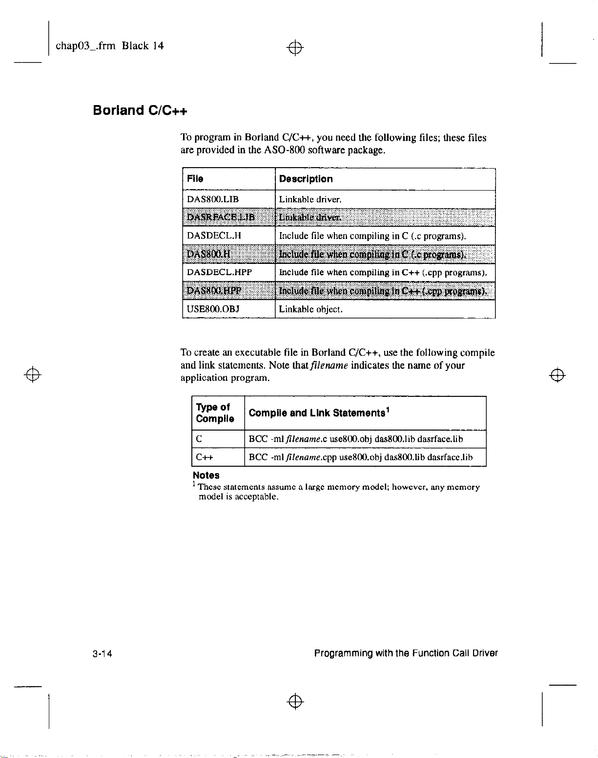
chap03-.frm Black 14
Borland C/C++
To program in Borland C/C++, you need the following files; these files
are provided in the ASO- software package.
File Description
1 DASBOO.LIB
DASDECL.HPP Include file when compiling in C++ (.cpp programs).
USE800.0B.l
1 Linkable driver.
Linkable object.
I
To create an executable file in Borland C/C++, use the following compile
and link statements. Note thatfilennme indicates the name of your
application program
lE;:e I
C
c++
Notes
’ These statements assume a large memory model; however. any memory
model is acceptable.
Compile and Llnk Statements’
BCC -ml~lename.c useEMI.obj das800.lib dasrfacc.lib
BCC -mljilename.cpp us&OO.obj das800,lib dasrface.lib
3-14
Programming with the Function Call Driver
Page 66

chap03-.frm Black 15
Microsoft QuickC for Windows
To program in Microsoft QuickC for Windows, you need the following
files; these files are provided in the ASO- software package.
File Description
DASSHELL.DLL Dynamic Link Library
DASROO.DLL Dynamic Link Library of DAS-800 board-specific
functions.
To create an executable file in Microsoft QuickC for Windows. perform
the following steps:
1. Loadfi/ename.c into the QuickC for Windows environment, where
filename indicates the name of your application program.
2. Create a project file. The project file should contain all necessary
files, includingfi/ename.c,filename.rc,fi/ename.def, andfi/enrmw.h,
wherefilename indicates the name of your application program.
3. From the Project menu, choose Build to create a stand-alone
executable file (.EXE) that you can execute from within Windows.
of user-interface functions.
3-l 5
Page 67

chap03-.frm Black 16
Microsoft Visual C++
To program in Microsoft Visual C++. you need the following tiles; these
files are provided in the ASO- software package.
1 File Description
Refer to the README.TXT file for information about creating an
executable tile in Visual C+t.
Borland Turbo Pascal
To program in Borland Turbo Pascal, you need the following files; these
files are provided in the ASO- software package.
File
1 DEOOTP6.TPU
DBCOTPU.BAT’
Notes
’
Used for
Pascal
3-l 6
creating a new
for versions higher than 7.0.
Description
Turbo Pascal unit for Version 6.0.
Batch file for creating a Turbo Pascal unit.
Turbo Pascal
unit when compiling in Borland Turbo
Programming with the Function Call Driver
I
Page 68

chap03-.frm Black 17
Borland Turbo Pascal for Windows
To create an executable tile in Borland Turbo Pascal, use the following
compile and link statement:
TPC filename.pas
wherefilename indicates the name of your application program,
Refer to page 3- 18 for information about specifying the buffer address
when programming in Borland Turbo Pascal. Refer to page 3-19 for
information about specifying the channel-gain list starting address when
programming in Borland Turbo Pascal.
To program in Borland Turbo Pascal for Windows, you need the
following files; these files are provided in the ASO- software
package.
File
Description
ynamic Link Library
of
DAS-800
board-specific
To create an executable file in Borland Turbo Pascal for Windows,
perform the following steps:
1. Loadfi/ename.pas into the Borland Turbo Pascal for Windows
environment, wherefiletxzme indicates the name of your application
program.
2. From the Compile menu, choose Make.
3-l 7
Page 69
chap03-.frm Black 18
Specifying the Buffer Address (Pascal)
Refer to the next section for information about specifying the buffer
address when programming in Borland Turbo Pascal for Windows. Refer
to page 3-19 for information about specifying the channel-gain list
starting address when programming in Borland Turbo Pascal for
Windows.
If you are writing your application program in Borland Turbo Pascal or
Borland Turbo Pascal for Windows, perform the following steps to
specify a buffer address:
I Reduce the memory heap reserved by Pascal by entering the
following:
($m
(16384, 0, 0))
2.
Declare a dummy type array of Alnteger, as in the following example:
TYPO
IntArray : Array[O..ll of ^Integer;
The dimension of this array is irrelevant; it is used only to satisfy
Pascal’s type-checking requirements.
3. Declare an array of the dummy type, as in the following example:
“ZllZ
acqBuf : IntArray;
. . .
4. If you are allocating your buffer dynamically using K~lnt4lloc. use
Pascal’s Addr() function, as in the following example:
5.
Use
err :
K-SetBuf
= K-IntAlloc (frameHandle, samples,
Addr(acqBuf), menHandle);
to specify the buffer address, as in the following
example:
err :
= K-SetBuf (frameHandle, acqBuf, samplesI;
3-1
a
Programming with the Function Call Driver
Page 70

chap03-.frm Black 19
Specifying the Channel-Gain List Starting Address (Pascal)
This procedure allows you to directly access data stored in the buffer. You
can retrieve data from the buffer, as in the following example:
Foi' I := 0 to (samples - 1) do
Begin;
data := acqBuf^[I];
End;
If you are writing your application program in Borland Turbo Pascal or
Borland Turbo Pascal for Windows, perform the following steps to
specify a channel-gain list starting address:
1. Define a record type for the channel-gain list. as in the following
example:
TYPO
ChanGainArray = Record;
num-of-codes : Integer;
queue : Array[O..lS] of Byte;
end;
2. Define an array of type ChanGainArray. as in the following example:
var
CGList : ChanGainArray;
.
3. After this is initialized. the array can be passed lo the function, LS in
the following
err :
= K_SetChnGAry (ADFramel, CGList.num-of-codes);
example:
3-19
Page 71

chap03-.frm Black 20
Microsoft QuickBASIC (Version 4.0)
To program in Microsoft QuickBASIC (Version 4.0), you need tbe
following tiles; these files are provided in the DA%300 Series standard
software package.
File Description
DgOOQB40,LIB
Linkable driver for QuickBASIC. Version 4.0.
stand-alone. executable (.EXB) Droarams. I
1 OB4DECL.BI
DASXOO.BI
1 Include file. I
Include file.
For Microsoft QuickBASIC (Version 4.0). you can create an executable
file from within the programming environment, or you can use a compile
and link statement.
To create an executable file from within the programming environment.
perform the following steps:
1. Enter the following to invoke the environment:
QB /L D800QB40 filename.bas
wherefilename indicates the name of your application program
3-20
2. From the Run menu, choose Make EXE File.
To use a compile and link statement, enter the following:
BC filename.bas /O
Link filename.obj,,,
D800QB40.lib+BCOM40.lib:
wherefilename indicates the name of your application program.
Refer to page 3-25 for information about specifying the buffer address
when programming in Microsoft QuickBASIC (Version 4.0).
Programming
with the Function Call Driver
Page 72

chap03-.frm Black 21
Microsoft QuickBasic (Version 4.5)
To program in Microsoft QuickBasic (Version 4.5), you need the
following files; these files are provided in the DAS-800 Series standard
software package.
File Description
DBOOQB45.LIB
QB4DECLBI
For Microsoft QuickBasic (Version 4.5), you can create an executable file
from within the programming environment, or you can use a compile and
link statement.
To create an executable file from within the programming environment,
perform the following steps:
1, Enter the following to invoke the environment:
QB /L DBOOQB45 filename.bas
Linkable driver for QuickBasic. Version 4.5.
sraad-alone, execurable (.EXE) programs.
Include tile.
-1
I
wherejifilename indicates the name of your application program.
2. From the Run menu. choose Make EXE File
To use a compile and link statement, enter the following:
BC filename.bas /O
Link filename.obj,,,
wherefilename indicates the name of your application program.
Refer to page 3-25 for information about specifying the buffer address
when programming in Microsoft QuickBasic (Version 4.5).
DBOOQB45.lib+BCOM45.lib;
3-21
Page 73

chap03Lfrm Black 22
Microsoft Professional Basic (Version 7.0)
To program in Microsoft Professional Basic (Version 7.0). you need the
following tiles; these files are provided in the DA.%800 Series standard
software package.
File Description
D8OOQBX.LIB Linkable driver for Professional Basic. Versions 7.0 and
higher, stand-alone, executable (.EXE) programs.
For Microsoft Professional Basic (Version 7.0), you can create an
executable file from within the programming environment, or you can use
a compile and link statement.
To create an executable file from within the programming environment,
perform the following steps:
1. Enter the following to invoke the environment:
QBX IL DElOOQBX filename.bas
wherefilename indicates the name of your application program
2. From the Run menu, choose Make EXE File.
To use a compile and link statement, enter the following:
BC filename.bas /o;
Link filename.obj,,,D800QBX.lib;
wherefilename indicates the name of your application program.
Refer to page 3-25 for information about specifying the buffer address
when programming in Microsoft Professional Basic (Version 7.0).
3-Z
Programming with the Function Call Driver
Page 74

chap03-.frm Black 23
Microsoft Visual Basic for DOS
To program in Microsoft Visual Basic for DOS, you need the following
files; these tiles are provided in the DAS-800 Series standard software
package.
DAS800.BI
Include file.
To create an executable tile in Microsoft Visual Basic for DOS, perfoml
the following steps:
1, Invoke the Visual Basic for DOS environment by entering the
following:
VBDOS /L D800VBD.QLB filename.BAS
wherefilename indicates the name of your application program
2. From the Run menu, choose Make EXE File.
Refer to page 3-25 for information about specifying the buffer address
when programming in Microsoft Visual Basic for DOS.
3-23
Page 75

chap03-.frm Black 24
Microsoft Visual Basic for Windows
+b
To program in Microsoft Visual Basic for Windows, you
following tiles; these files are provided in the ASO- software
package.
File
DASSHELL.DLL
DASBOO.DLL
1 DAS8OO.BA.S
To create an executable file from the Microsoft Visual Basic for Windows
environment, choose Make EXE File from the Ron menu.
Refer to the next section for information about specifying the buffer
address when programming in Microsoft Visual Basic for
Description
Dynamic Link Library of user-interface
functions.
Dynamic Link Library of DAS-KKI
board-specific functions.
Include tile: must be added to the Project List.
need the
I
I
Windows.
3-24
Programming
with the Function Call Driver
Page 76

chap03-.frm Black 25
Specifying the Buffer Address (All BASIC Languages)
This section describes how to specify a buffer address when programming
in BASIC and Visual Basic for Windows.
4
For Visual Basic for
dynamically using K-IntAlk,
buffer address:
1. Declare the allocated buffer pointer, as in the following example:
Global AllocBuf As Long
2. Allocate the buffer, as in the following example:
errnun = K-IntAlloc IframeHandle, samples,
AllocBuf,
Refer to page 4-78 for more information about the K-IntAlloc
function.
3. In defining the elements of your frame, specify the buffer address, as
in the following example:
errnum = K-SetBuf (frameHandle, AllocBuf, samples)
Refer to page 4-95 for more information about the K-SetBuf
function.
Windows,
ifyou are allocating your buffer
perform the following steps to specify the
manHandle)
4
4. After all your data is acquired, move the data from the allocated
buffer to a local storage buffer that your program can access, as in the
following example:
errnum = K-MoveBufToArray (BufferCOl,
samples)
Refer to page 4-88 for more information about the
K-MoveRufIbArray function.
AllocBuE.
4
3-25
Page 77

chap03-.frm Black 26
For BASIC and Visual Basic for Windows, ifyou awdimensioning your
buffer locally, perform the following steps to specify the buffer address:
1. Declare the local buffer, as in the following example:
Global Buffer(20000) As Integer
2. In defining the elements of your frame, specify the buffer address, as
in the following example:
errnum = KLSetBufI (frameHandle, Buffer(O),
samples)
Refer to page 4-97 for more information about the K-SetBufl
function.
Notes: The local buffer is accessible to your program; you do not have to
use. K-MoveButToArray to move it.
Do not use underscores in the BASIC languages.
3-26
Programming with the Function Call Driver
Page 78

chap04-.frm Black 1
Function Reference
The FCD functions are organized into the following groups:
.
Initialization functions
.
Operation functions
.
Frame management functions
.
Memory management functions
.
Buffer address functions
.
Buffering mode functions
.
Channel and gain functions
.
Conversion clock functions
.
Trigger functions
.
Counter/timer functions
.
Miscellaneous functions
4-l
Page 79

chap04-.frm Black 2
The particular functions associated with each function group are
presented in Table 4- 1. The remainder of the chapter presents detailed
descriptions of all the FCD functions, arranged in alphabetical order.
Table 4-l. FCD Functions
Function Type
Initialization
Function Name
K GetADFrame
Page Number
Function Fielerence
Page 80

chap04-.frm Black 3
Table 4-1. FCD Functions (cont.)
Buffering Mode
Page 81

chap04-.frm Black 4
4-4
Function Reference
Page 82

‘I$
chap04-.frm Black 5
Keep the following conventions in mind throughout this chapter:
Although the function names are shown with underscores, do not use
the underscores in the BASIC languages.
The data types DDH. FRAMEH. DWORD. WORD, and BYTE are
defined in the language-specific include tiles.
Variable names are shown in italics.
The return value for all FCD functions is the error/status code. Refer
to Appendix A for more information.
The syntax shows the format of the function and the data types of the
parameters. This line of code is not necessarily the exact line of code
you would enter in your application program. In addition. data types
must be defined before you enter the line of code.
Entry parameters are parameters that are passed to the function but
not changed by the function.
Exit parameters are parameters that are modified by the function.
In the examples, the variables are not defined. It is assumed that they
are defined as shown in the syntax.
4-5
Page 83

chap04-.frm Black 6
DAS800-DevOpen
Purpose
Syntax
Entry Parameters
Initializes the DAS-800 Series Function Call Driver.
c
DAS800-DevOpen
char
*c&File;
char
*numDevices;
Pascal
DAS800-DevOpen (c&File.
(&File, num&vices);
numDevices) :
Word:
c&File : String;
numDevices :
Visual Basic for Wlndows
DASSOO-DevOpen
Dim
&File
Dim
rumDevices
Integer;
(cfgFile, nunDevices)
As String
As Integer
As
Integer
BASIC
DASXOODevOpen%
(c&file, turnDevices)
Dim c&File As String
Dim
numDevices
cfgFile
As Integer
Driver configuration tile.
Valid values: 0 = DASSOO.CFG
-I= Default configuration
filename = Any configuration tile
Exit Parameters
Notes
4-6
turnDevices
Number of boards defined in
cfgFile.
Valid values: 1 to 4
This function initializes the driver according to the information in the
configuration tile specified by
defined in
rumDevices.
cfgFile
and stores the number of boards
You create a configuration file using the D800CFG.EXE utility. Refer to
the
DAS-800 Series
User’s
Guide
for more information.
Function Reference
Page 84

chap04-.frm Black 7
If cfgFile
= 0, DAS800~DevOpen
looks for the DASKM.CFG
configuration tile in the current directory and uses those settings. if
available. If
&File
=-I, DASt?OO-DevOpen
initializes the driver to its
defauault configuration; the default configuration is shown in Table 4-2.
Table 4-2. Default Configuration
Attribute Default Configuration
I
Page 85

chap04-.frm Black 8
The Function Call Driver requires null terminated strings. To create null
terminated strings in Pascal, BASIC, and Visual Basic for Windows, refer
to the following examples. These examples assume that the configuration
file
(c&File)
is DASZ(OO.CFG.
Example
Pascal:
BASIC and Visual Basic for Wlndows:
&File : =
cfgFile =
‘DAS8OO.CFG’ + #O;
“DAS800,CFG” + CHR$(O)
After you set up your DAM01 board, you created a configuration file to
reflect the settings of the jumper and switches on the board. The name of
the configuration tile is stored in the memory location pointed to by
CONFSOI. You want to initialize the DAS-800 Series Function Call
Driver according to this configuration tile and store the number of boards
defined in the configuration file in a variable called NumberOtBoards.
C
char NumberOfBoards;
err = DAS800-DevOpen (CONFBOI, &NumberOtBoards);
Pascal
err : = DAS800-DevOpen (CONF801[1], NumberOfBoards);
Visual Basic for Windows
ermum = DAS800-DevOpen (CONFBOI. NumberOfBoards)
BASIC
errnum = DAS800DevOpen% (CONFXOl. NumberOfBoards)
4-8
Function Reference
Page 86

chap04-.frm Black 9
fb
DASBOO-GetADGainMode
Purpose
Syntax
Entry Parameters
Gets the current input range type (unipolar or bipolar).
c
DASBOO-GetADGainMode
short
devhrumber;
short
*mode;
Pascal
DAS800-GetADGainMode
devNumber
mode
Visual Basic for Windows
: Integer;
: Integer;
DASSOO-GetADGainMode
Dim
devNumber
Dim
mode
BASIC
As Integer
As Integer
DASBOOGetADGainMode%
Dim
devNumber
Dim
mode
devNumber
As
Integer
As Integer
Board number.
(devNumber, mode);
(devNumber, mode)
(devNumber, mode)
(devNumber, mode)
: Word;
As Integer
Valid values: 0 to 3
Exit Parameters
Notes
mode
Input range type.
Value stored: 0 = Unipolar
For the board specified by
devNumber,
range type and stores it in mode.
1 = Bipolar
this function gets the. current input
4-9
Page 87

chap04-.frm Black 10
Example
You want to store the current input range type for board 1 in a variable
called ADModel.
c
short ADMode I ;
err = DAS800-GetADGainMode (1, &ADModel);
Pascal
err : = DAS800-GetADGainMode (I, ADModel);
Visual Basic for Windows
errnum = DAS800_GetADGainMode% (1. ADModel)
BASIC
errnum = DASgOOGetADGainMode% (I, ADModel)
Function
Reference
Page 88

chap04-.frm Black 11
DAS800-GetDevHandle
Purpose
Syntax
Entry Parameters
Initializes a DAS-800 Series board.
c
DAS800-GetDevHandle
short
devNumber;
DDH
*devHandle;
Pascal
DAS800-GetDevHandle
devNumber
devHandle
Visual Basic for Windows
: Integer;
: Longint;
DAS800-GetDevHandle
Dim
devNumber
Dim
devHandle
As Integer
As Long
(devNumber, devHandle);
(devNumber, devHandle) :
(devNumber, devHand/e)
BASIC
DAS800GetDevHandle%
Dim
devNumber
Dim
devHand/e
devNumber
As Integer
As Long
(devNumber. devtlandle)
Board number.
Valid values: 0 to 3
Word;
As Integer
Exit Parameters
Notes
devHandle
This function initializes the board specified by
board handle of the specitied board in
The value stored in
Handle associated with the board.
devhrumber,
devHmdle.
devHandle
is intended to be used exclusively as an
and stores the
argument to functions that require a board handle. Do not modify the
value stored in
devHandle.
4-11
Page 89

chap04-.frm Black 12
Example
You want to initialize board 1 and to associate board 1 with a board
handle called BrdHd 1.
C
DDH BrdHdl;
err = DAS800-GetDevHandle (1, &BrdHdl);
Pascal
err : = DAS800-GetDevHandle (I, BrdHdl);
Visual Basic for Windows
errnum = DAS800-GetDevHandle (1. BrdHdl)
BASIC
errnum = DAS80OGetDevHandle% (1, BrdHdl)
4-12
Function Reference
Page 90

chap04_.frm Black 13
DAS800-Get8254
Purpose
Syntax C
Gets status of the 8254 counter/timer circuitry.
DAS800-Get8254
short
short counter;
short
unsigned long ‘count;
Pascal
DAS800-Get8254
devNumber
counter : Integer;
mode
count : Longint;
Visual Basic for Windows
DAS800-Get8254
Dim
Dim counter As Integer
Dim
Dim count As Long
BASIC
DAS80OGet8254%
Dim
Dim counter As Integer
Dim
Dim count As Long
devhrumber;
*mode;
: Integer:
: Integer;
devNumber
mode
As integer
devNumber
mode
As Integer
(devNumber. counter, mode, count);
(devNumber, counter, mode,
(devNumber, counter, mode. counr)
counl) : Word;
As Integer
(devNumber, counter. mode, count)
As Integer
As Integer
Entry Parameters
devNurnber
counter
Board number.
Valid values: 0 to 3
Counter/timer.
Valid values: 0 = C/TO
l=C/rl
2=crr2
4-13
Page 91

chap04-.frm Black 14
Exit Parameters
Notes
Example
mode
count Value of counter/timer.
For the counter/timer specified by counter on the 8254 counter/timer
circuitry on the board specified by
counter/timer mode in
COUIU.
Refer to the
counter/timer modes.
You want to store the counter/timer mode of C/TO on board 1 in a variable
called CTOMode and the value currently loaded in C/TO on board I in a
variable called CTOConnt.
DAS-800 Series
Counter/timer mode.
Value stored: 0 = Pulse on terminal count
1 = Programmable one-shot
2 = Rate generator
3 = Square-wave generator
4 = Software-triggered strobe
5 = Hardware-triggered strobe
Value stored: 0 to 65535
devhrumber,
mode
and the current value of the counter/timer in
User’s
Guide
this function stores the
for an explanation of the
4-14
C
short CTOMode;
unsigned long CTOCount:
err = DAS800-Get8254 (1, 0, &CfOMode, &CTOCount);
Pascal
err : = DAS800-Get8254 (1, 0, CTOMode, CTOConnt);
Visual Basic for Windows
ermum =
BASIC
errnnm = DAS800Get8254% (1,O. CTOMode, CfOConnt)
DAS800-Get8254 (1.0, CTOMode, CTOCount)
Function Reference
I
+B
Page 92

chap04-.frm Black 15
DAS800-SetADGainMode
Purpose
Syntax
Entry Parameters
Sets the input range type (unipolar or bipolar).
c
DASBOO-SetADGainMode
short
devhrumber;
short
mode;
Pascal
DAS800JWADGainMode
devNumber :
mode :
Visual Basic for Windows
Integer;
Integer;
DAS800-SetADGainMode
Dim
devNumber
Dim
mode
As Integer
As Integer
(devNumber. mode);
(devNumber. mode) :
(devNumber. mode)
BASIC
DASBOOSetADGainMode%
Dim
devNumber
Dim
mode
devNumber
As Integer
As Integer
Board number.
(devNumber. mode)
Valid values: 0 to 3
Word;
As Integer
Notes
mode
Input range type.
Valid values: 0 = Unipolar
1 = Bipolar
For the board specified by
type to
mode.
devNumber,
this function sets the input range
This function is appropriate for DAS-801 and DAS-802 boards only. The
DAS-800 board is always configured for a f5 V bipolar analog input
range type.
4-15
Page 93

chap04Lfrm Black 16
Example
The configuration file for board I specifies a bipolar input range type.
You want to change the input range type to unipolar.
C
err = DAS800-SetADGainMode (1.0);
Pascal
err : = DAS800-SetADGainMode (I, 0);
Visual Basic for Windows
errnum = DASBOO-SetADGainMode (1.0)
BASIC
ennum = DASSOOSetADGainMode% (I, 0)
4-16
Function Reference
Page 94

chap04-.frm Black 17
DAS800-Set8254
Purpose
Syntax C
Sets up the 8254 counter/timer circuitry.
DAS800Jet8254
short
short counter;
short
unsigned long count;
Pascal
DAS800-Set8254
devNumber
counter
mode
counf
Visual Basic for Windows
DAS800-Set8254
Dim
Dim counter As Integer
Dim
Dim count As Long
BASIC
DAS800Set8254%
Dim
Dim counfer As Integer
Dim
Dim count As Long
devNumber;
mode;
: Integer:
: Integer;
: Integer;
: Longint;
devNumber
mode
As Integer
devNumber
mode
As Integer
(devNumber, counter. mode, count);
(devNumber. counter. mode, count) :
(devNumber, counter, mode, count)
As Integer
(devNumber, counter, mode, count)
As Integer
Word;
As Integer
Entry Parameters
devNumber
counter
Board number.
Valid values: 0 to 3
Counter/timer.
Valid values: 0 = C/TO
l=C/TI
2=cfr2
4-17
Page 95

chap04-.frm Black 18
Notes
Example
mode
Counter/timer mode.
Valid values: 0 = Pulse on terminal count
1 = Programmable one-shot
2 = Rate generator
3 = Square-wave generator
4
= Software-triggered strobe
5 = Hardware-triggered strobe
COUTU
Value of counter/timer.
Valid values: 2 to 65535
For the counter/timer specified by counter on the 8254 counter/timer
circuitry on the board specified by
counter/timer mode to
Refer to
the DAM00 Series User’s Guide
mode
devhrumber,
this function sets the
and the initial count value to counr.
for an explanation of the
counter/timer modes and for more information about the 8254
counter/timer circuitry.
You want to configure C/IO on board 1 as a software-triggered strobe and
load an initial count value of 100 into C/TO.
C
err = DAS800-Set8254 (I, 0.4. 100);
4-1 B
Pascal
err : = DAS800-Set8254 (1.0,4, 100);
Visual Basic for Windows
errnum = DAS800-Set8254 (I, 0.4, 100)
BASIC
ermum = DAS800Set8254% (1.0.4, 100)
Function Reference
Page 96

chap04-.frtn Black 19
K ADRead
Purpose
Syntax c
Reads a single analog input value.
K-ADRead
DDH
unsigned char
unsigned char
void
Pascal
K-ADRead
devHandle
than :
gaincode :
ADvalue
Visual Basic for Windows
K-ADRead
Dim
Dim
Dim
Dim
BASIC
KADRead%
Dim
Dim
Dim
Dim
(devHandle, than, gainCode. ADvalue);
devHand/e;
*ADvalue;
(devHandle, chart, gaincode, ADvalue)
: Longint;
Byte;
Byte;
: Pointer;
(devHandle, chart, gainCode, ADvalue)
devHandle
than
As Integer
gainCode
ADvalue
(devHand/e, than, gaincode, ADvalue)
devHandle
than
As Integer
gainCode
ADvalue
than;
gainCode;
: Word;
As Integer
As Long
As Integer
As Long
As Long
As Integer
As Long
Entry Parameters
devHandle
than
Handle associated with the board
Analog input channel.
Valid values: 0 to 127
4-19
Page 97

chap04-.frm Black 20
Exit Parameters
Notes
gainCode
Gain code.
Valid values:
DAS-802
Gain
ADvalue
This function reads the analog input channel
by
devHand/e
count in
ADvalue.
The range of valid values for
Acquired analog input value.
at the gain represented by
than
depends on the number of expansion
than
gaincode,
on the board specified
and stores the raw
boards you are using. Refer to page 2-6 for more information.
4-20
A gain of 0.5
(gainCode
= 1) is valid only for boards configured with a
bipolar input range type. The DAS-800 board supports a gain of I only
(g&Code
must equal 0). Refer to Table 2-2 on page 2-6 for a list of the
voltage ranges associated with each gain.
Make sure that the variable used
to
store
ADvalue
is dimensioned as a
1 h-bit integer.
Refer to Appendix B for information on converting the raw count stored
in
ADvalue
to voltage.
Function Reference
Page 98

chap04-.frm Black 21
Example
You want to perform an analog input operation on a DAS-801 board that
was assigned the hoard handle BrdHdl, You want to read the value of the
signal connected to analog input channel 3 at a gain of IO and store the
raw count in a variable called Chn3Val.
c
short Chn3Val;
err = K-ADRead (BrdHdl. 3.2, &Chn3Vai);
Pascal
err : = K-ADRead (BrdHdl, 3.2, Chn3Val);
Visual Basic for Windows
errnum = K-ADRead (BrdHdl. 3,2. Chn3Val)
BASIC
ermum = KADRead% (BrdHdl, 3.2, Chn3Val)
4-21
Page 99

chap04-.frm Black 22
K BufListAdd
Purpose
Adds a buffer to the list of multiple buffers,
c
K-BufListAdd
(frameHandle, acqBuf, samples);
FRAh4EHframeHandle;
void
*acqBuf;
DWORD
samples;
Pascal
K-B&&Add
frameHandle
acqBuf
samples
: Pointer;
: Longint:
(frameHandle, acqBuf, samples)
: Longint;
Visual Basic for Windows
K-BufListAdd
Dim
frameHandle
Dim
acqBuf
Dim
samples
(frameHandle, acqBuf, samples)
As Long
As Long
As Long
BASIC
KBufListAdd%
Dim
frameHandle
Dim
acqBuf
Dim
samples
(frameHandle, acqBaf* samples)
As Long
As Long
As Long
: Word;
As Integer
Entry Parameters
Notes
4-22
frameHandle
acqBuf
samples
For the operation defined by
the address pointed to by
Handle to the frame that defines the A/D operation.
Starting address of buffer.
Number of samples in the buffer.
frameHandle,
acqBuf
to the list of multiple buffers; the
this function adds the buffer at
number of samples in the buffer is specified in
samples.
Function Reference
Page 100

chap04-.frm Black 23
Example
You must either allocate the buffer dynamically using
K-IntAlloc 01
dimension the buffer locally before you add the buffer to the
multiple-buffer list.
Make sure that you add buffers to the multiple-buffer list in the order in
which you want to use them. The first buffer you add is Buffer I, the
second buffer you add is Buffer 2. and so on. You can add up to 50
buffers. For interrtrpt-mode operations, you
can use K-IntStatus
to
determine which buffer is currently in use; refer to page 4-83 for more
information.
You allocated a 1000~sample buffer to store data for an analog input
operation defined by the frame ADFramel; the buffer starts at the
memory location pointed to by Buffer. You want to add this buffer to the
list of multiple buffers.
C
err = K-BufListAdd (ADFramel, Buffer, 1000);
Pascal
err : = K-BufListAdd (ADFramel, Buffer, 1000);
Visual Basic for Wlndows
errnum = K-BufListAdd (ADFramel, Buffer, 1000)
BASIC
ermum = KButListAdd% (ADFramel, Buffer, 1000)
4-23
 Loading...